download - worcester polytechnic institute
TRANSCRIPT
Project: JB3-CBS1
Mechanical, Power, and Propulsion Subsystem Design for a CubeSat
A Major Qualifying Project Submitted to the Faculty
of WORCESTER POLYTECHNIC INSTITUTE
in partial fulfillment of the requirements for the Degree of Bachelor of Science
in Aerospace Engineering
by
Keith Cote
Jason Gabriel
Brijen Patel
Nicholas Ridley
Zachary Taillefer
Stephen Tetreault
7 March 2011
Prof. John Blandino, Project Advisor

2
Abstract This project explores Worcester Polytechnic Institute’s (WPI) initial venture in
experimenting with a type of picosatellite called a CubeSat. Three Major Qualifying Projects
(MQP) representing seven subsystems collaborated on the construction of a ground-based
CubeSat to test current technologies and investigate the feasibility of future CubeSat
projects at WPI. Of the seven CubeSat subsystems, this report outlines efforts of the power,
propulsion, and structure subsystems. Research on previous and current CubeSat projects
provided baseline information, giving teams the ability to select components for a “Lab
Option” as well as “Flight Option” CubeSat.
Although construction and testing of a full Lab Option CubeSat was beyond the
scope of this project, each of the three subsystems teams were able to design and/or
construct a baseline set of components for their subsystem and perform rudimentary
testing. The extensive research and recommendations detailed herein will be used by
future groups to prepare a space-ready satellite. In addition, this project (in conjunction
with two other CubeSat design teams) resulted in a fully defined Flight Option CubeSat,
including component selection and mission planning, for a 3U CubeSat carrying an Infrared
Spectrometer.

3
Acknowledgements This project would not have been possible without the assistance of our advisor:
Professor John J. Blandino, Ph.D.
Associate Professor, Aerospace Engineering Program
Department of Mechanical Engineering, Worcester Polytechnic Institute
Special thanks as well to the advisors for the other CubeSat design teams:
Professor Michael Demetriou, Ph.D.
Professor, Aerospace Engineering Program
Department of Mechanical Engineering, Worcester Polytechnic Institute
Professor Nikolaos Gatsonis, Ph.D.
Director, Aerospace Engineering Program
Department of Mechanical Engineering, Worcester Polytechnic Institute

4
Authorship Nicholas Ridley and Jason Gabriel wrote the Abstract, Lists, Executive Summary,
Introduction, Mission and Payload Literature Review, Goals, Methodology chapters, and the
Power Literature Review. Keith Cote and Brijen Patel wrote the Mechanical Structures
Literature Review. Stephen Tetreault and Zachary Taillefer wrote the Propulsion Literature
Review. All group members edited and revised various sections. In its final form, this report
contains equal contributions from all group members, and each section represents the
collaborative effort of multiple authors.

5
Table of Contents 1 Introduction ............................................................................................................................ 11
1.1 Project Goals and Objectives ................................................................................................ 12
1.2 Power Subsystem Objectives ............................................................................................... 13
1.3 Propulsion Subsystem Objectives...................................................................................... 13
1.4 Mechanical Structure Subsystem Objectives ................................................................ 14
2 Background ............................................................................................................................. 16
2.1 General CubeSat Specifications ........................................................................................... 17
2.1.1 Power Subsystem Specifications ................................................................................ 17
2.1.2 Propulsion Subsystem Specifications ....................................................................... 17
2.1.3 Mechanical and Structural Subsystem Specifications ...................................... 18
2.2 Power Subsystem ...................................................................................................................... 21
2.2.1 Solar Cells ............................................................................................................................... 21
2.2.2 Batteries.................................................................................................................................. 22
2.2.3 Power Management and Distribution System (PMAD) ................................... 23
2.2.4 Sample CubeSat Power Systems ................................................................................. 24
2.3 Propulsion Subsystem ............................................................................................................. 26
2.3.1 Pulsed Plasma Thrusters (PPT) .................................................................................. 26
2.3.2 Vacuum Arc Thrusters (VAT) ....................................................................................... 28
2.3.3 Resistojets .............................................................................................................................. 29
2.3.4 Liquefied Gas Thrusters .................................................................................................. 30
2.3.5 Cold Gas Thrusters ............................................................................................................ 31
2.4 Mechanical and Structural Subsystem ............................................................................ 33
2.4.1 Mass Produced CubeSat Structures ........................................................................... 34
2.4.2 Custom-Designed CubeSat Structures ..................................................................... 36
2.4.3 Summary of Structural Design Approaches .......................................................... 38
3 Methodology ........................................................................................................................... 40
3.1 Research ......................................................................................................................................... 40
3.2 System Engineering Group (SEG) ...................................................................................... 40
3.3 Construction ................................................................................................................................. 41
3.4 Lab Option vs. Flight Option ................................................................................................. 49
4 Lab Option Component Selection and Analysis ............................................................. 51
4.1 Spacecraft and Payload Requirements ............................................................................ 51
4.1.1 Orbit Specifications ........................................................................................................... 51
4.1.2 Scientific Payload ............................................................................................................... 52
4.2 Power Component Selection and Analysis .................................................................... 52
4.2.1 Solar Cells ............................................................................................................................... 53
4.2.2 Batteries.................................................................................................................................. 54
4.2.3 Power Management and Distribution (PMAD) .................................................... 55
4.3 Propulsion System Selection & Analysis ........................................................................ 57
4.3.1 Propulsion Analysis........................................................................................................... 61
4.3.2 Orbital Maneuvers ............................................................................................................. 61

6
4.3.3 Propellant Volume ............................................................................................................. 63
4.3.4 Atmospheric Drag .............................................................................................................. 65
4.4 Mechanical Structures Design Selection & Analysis ................................................. 66
5 Flight Option Component Selection and Analysis ......................................................... 72
5.1 Power Subsystem ...................................................................................................................... 72
5.1.1 Flight Option Solar Cells .................................................................................................. 73
5.1.2 Flight Option Battery ........................................................................................................ 73
5.1.3 Flight Option PMAD .......................................................................................................... 73
5.2 Propulsion Subsystem ............................................................................................................. 74
5.2.1 Flight Option ......................................................................................................................... 74
6 Results & Conclusions .......................................................................................................... 75
6.1 Power Conclusions .................................................................................................................... 75
6.1.1 Solar Cells ............................................................................................................................... 75
6.1.2 Batteries.................................................................................................................................. 75
6.1.3 PMAD ........................................................................................................................................ 76
6.2 Propulsion Conclusions .......................................................................................................... 76
7 Recommendations................................................................................................................. 77
7.1 Power Recommendations ...................................................................................................... 77
7.2 Propulsion Recommendations ............................................................................................ 77
7.3 Mechanical Structures Recommendations .................................................................... 78
8 References ............................................................................................................................... 80
Appendix A: Abbreviations and Variables .............................................................................. 85
Appendix B: CubeSat Design Specifications............................................................................ 86
Appendix C: CubeSat Database ................................................................................................... 91

7
List of Figures Figure 1 – 1U and 3U CubeSats [4] ............................................................................................ 16
Figure 2 – 1U CubeSat Specification Diagram [2] .................................................................. 18
Figure 3 – P-POD Exterior and Cross Section [2] ................................................................... 20
Figure 4 – Clyde Space Solar Cell [35] ...................................................................................... 22
Figure 5 – Flight-Ready PMAD from Clyde Space [35] ......................................................... 23
Figure 6 – Schematic of a typical PPT [6] ................................................................................ 26
Figure 7 – AFRL Micro PPT concept [21] ................................................................................. 27
Figure 8 – Micro PPT CAD drawing [13] .................................................................................. 28
Figure 9 – Micro Vacuum Arc Thruster used on ION ............................................................ 29
Figure 10 – VACCO MiPS design for a CubeSat [4] ................................................................. 30
Figure 11 – Monoblock CAD models for the CubeSat for the 3U size (left) and 2U size
(right) ................................................................................................................................... 42
Figure 12 – Modular design 1 assembly CAD model for a 3U CubeSat in exploded
(left) and collapsed configurations (right) ................................................................ 43
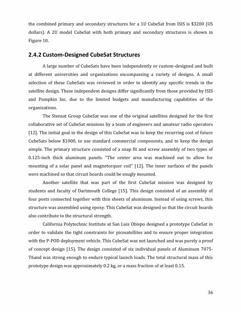
Figure 13 – Modular Design 2 CAD Assembly for a 3U CubeSat in exploded (left) and
collapsed configurations (right) ................................................................................... 44
Figure 14 – 3nd Modular CAD Assembly for a 3U CubeSat in collapsed (left) and
exploded configurations (right) .................................................................................... 45
Figure 15 – CAD Assembly model of Lab Assembly 1 in exploded (left) and collapsed
configurations (right) ...................................................................................................... 46
Figure 16 – CAD Assembly model of Lab Assembly 2 in exploded (left) and collapsed
configurations (right) ...................................................................................................... 47
Figure 17 – Haas Vertical Machining Center Toolroom Mill (TM-1) [51] ...................... 48
Figure 18 – Pocketing Operation [51] ..................................................................................... 49
Figure 19 – Completed Railed & Connecting Panels [51] .................................................... 49
Figure 20 – PMAD Block Diagram.............................................................................................. 56
Figure 21 – SERIES 411 Miniature Solenoid valves from ASCO Scientific, manifold
mount option (left) and standard option [56] .......................................................... 58
Figure 22 – Lab Option 1 SolidWorks model .......................................................................... 60

8
Figure 23 – Change in altitude or inclination for varying mass ratios ............................ 63
Figure 24 – Propellant Mass vs. Volume .................................................................................. 64
Figure 25 – Volume vs. pressure for different propellant masses at Tmin (top) and Tmax
(bottom) for 1U .................................................................................................................. 65
Figure 26 – CubeSat Structural Stress Analysis (von Mises Stress, Displacement,
Deformation (top to bottom) ......................................................................................... 70
Figure 27 – Schematic CAD model of test stand fixture in close-up (left) and
configured in the vacuum chamber (right) ................................................................ 78
Figure 28 – CAD Assembly monoblock design with subsystem components
configured inside ............................................................................................................... 79

9
List of Tables Table 1 – Critical Dimensions for 3 Primary CubeSat Sizes [2] ......................................... 19
Table 2 – Performance characteristics of MiPS [4] ............................................................... 31
Table 3 – Comparison of µPPT and cold gas propulsion systems (single thruster
performance) [20]............................................................................................................. 32
Table 4 – Summary of performance characteristics for propulsion options applicable
to CubeSats .......................................................................................................................... 33
Table 5 – CubeSat Structural Design Trend Categories ....................................................... 34
Table 6 – Orbital Characteristics ............................................................................................... 51
Table 7 – Argus 1000 IR Spectrometer Specifications [52] ................................................ 52
Table 8 – Lab Option Solar Cell Comparison [53] and [54] ................................................ 54
Table 9 – Lab Option Power Subsystem Components [55] ................................................. 57
Table 10 – ∆V calculations for varying mass ratios. ............................................................. 61
Table 11 – Properties of Aluminum 7075 [15] ...................................................................... 67
Table 12 – Typical Launch Loads of Past CubeSat Launch Vehicles [14] ........................ 68

10
Executive Summary In 1999, professors at California Polytechnic State University (Cal Poly) and
Stanford University outlined a set of specifications for a simple picosatellite, and the
CubeSat was born. A CubeSat is a small, relatively easy-to-construct, and relatively low-
cost, satellite based on a standardized design. The set of specifications is meant to “provide
a standard for design of picosatellites to reduce cost and development time, increase
accessibility to space, and sustain frequent launches” [42]. The target audience for this
satellite standard would be universities, who would construct satellites as a way to
introduce students to a realistic and practical spacecraft design and mission launch
process.
This project represents the work of three of the seven subsystem teams responsible
for the design, construction, and testing of a ground-based CubeSat. The collective
Aerospace MQP student group, consisting of three teams broken into seven smaller
subsystem teams was required to design a satellite to house the Argus 1000 IR
Spectrometer in a circular orbit with altitude 680 km and period of 98.2 minutes. Teams
researched laboratory and flight-qualified options for satellite components, accounting for
mission and scientific payload requirements. The “Lab Option” satellite will be constructed
and tested in WPI’s vacuum chamber by future MQP Groups, while a set of
recommendations will be put forth by all teams to comment on the requirements for a
space-ready “Flight Option” satellite to be built by future teams.
This report presents the research and design of the power, propulsion, and
structural subsystems. Our team spent the first of three seven week terms conducting
research into previous and current CubeSat technologies, which created a baseline
understanding of the technology and allowed us to explore technology applicable to our
particular satellite and mission.
11
1 Introduction
Space exploration and research is one of the most alluring and prestigious
endeavors within Aerospace Engineering. However, many engineering students do not get
the opportunity to work on space-oriented research until, at the earliest, the start of their
professional career. Moreover, the cost of sending vehicles and satellites into space
compounded with the enormity of work involved make for infrequent missions, meaning
engineers working on space systems often do not get many opportunities for the practice of
launch and flight operations. However, in 1999, the California Polytechnic State University,
San Luis Obispo [43] and Stanford University developed specifications for a class of
picosatellites. These picosatellites were given the term “CubeSat,” whose small design (1-3
liters) and relatively low cost (construction and launch: $65,000-80,000) appealed to
universities and companies worldwide [4]. Moreover, a standardized deployment system,
the Poly-Picosatellite Orbital Deployer (P-POD), allows for any CubeSat to be carried into
orbit (on a space-available basis) and deployed, as long as said satellite adheres to the
CubeSat criteria [4]. The ease of creating an operational satellite using readily available
electronics offers students the experience of mission planning and spacecraft design long
before they would receive similar on-the-job experience, making the construction and
launch of CubeSats an attractive tool for academia. Additionally, CubeSats are often
outfitted with a variety of scientific instruments, although it is important to note that due to
the size and power available to a CubeSat, satellites typically support only two instruments
at most. This allows a CubeSat to serve a practical purpose in addition to its educational
value. Moreover, CubeSats provide researchers not affiliated with the university developing
the CubeSat with a low-cost space vehicle with which to conduct research. In some cases,
these external researchers provide CubeSat teams with the funding support.
In the spring of 2010, Professors Gatsonis, Blandino, and Demetriou, of the WPI
Aerospace Program (Mechanical Engineering Dept.) initiated the university's first effort in
the area of CubeSat research and development. An eleven person team of fourth year
undergraduate Aerospace students was formed to research and develop the various
subsystems of a satellite as part of their Major Qualifying Project (MQP), exploring the
potential of this technology through the construction and testing of a ground-based

12
engineering model. Individuals were divided into three MQP teams representing seven
subsystems, with each team assigned a different advisor. This report outlines the work
done by the Power, Propulsion, and Mechanical Structures subsystem teams (other
subsystems include Thermal Control, Payload, and Attitude Control and Dynamics). Teams
were responsible for researching Lab and Flight Options for the satellite, coordinating
efforts and tasks for satellite construction, and eventually testing the Lab Option satellite.
The Lab Option is defined as a satellite constructed primarily with off-the-shelf parts to fit
within the project’s limited budget (approx. $2000). In addition, the Lab Option involved
other cost-saving measures such as replacing the scientific payload or other expensive
components with “black box” components (to simulate mass properties), or the use of a
power umbilical to simulate different solar cell and battery power sources using laboratory
power supplies.
The results of this MQP will lay the groundwork for future CubeSat groups. A set of
conclusions and recommendations will be published, which will allow groups to apply
lessons learned to development of a space-ready, or “Flight Option” satellite in the future.
1.1 Project Goals and Objectives
The primary goal of this project was to coordinate with two other MQP projects
comprising seven subsystems to design, build, integrate, and test a single ground-based
CubeSat, which incorporates key elements from each of the included subsystems. This
allowed us to establish a baseline design for the CubeSat subsystems, and lay the
groundwork for future CubeSat projects at WPI, which could lead to space-ready satellites.
Our objectives for this project were to:
Select components for both a “lab” and “flight” option CubeSat
Integrate these subsystems
Construct a Lab Option satellite as a “proof of concept” which can be used for
hardware/software testing and construct a test fixture to support the Lab Option
CubeSat in a vacuum chamber
Perform testing of the completed Lab Option CubeSat in a vacuum chamber
Create a set of recommendations for the Flight Option CubeSat for future groups to

13
reference
As the initial CubeSat project at WPI, much of our work will lead to improvements in
the organizational structure and planning of the project, as well as the establishment of a
baseline design for future groups.
1.2 Power Subsystem Objectives
The purpose of a power system on a satellite is to produce, store, manage, and
distribute power to the systems that need it. In the case of this project, the power team’s
objectives were twofold. First, the power subsystem team was responsible for designing
both a lab and flight option power system to include the four necessary functions stated
above. This design needed to include specific details regarding the power system, including
the amount and type of power provided, power needs of users, and specific components
such as DC-DC converters, on/off switches, and battery management components.
Moreover, the design needed to show the appropriate circuitry required to make each
component function. Secondly, the power team needed to construct and test the Lab Option
power system. While the Flight Option plan was intended for project continuity, the Lab
Option needed to be constructed to allow preliminary testing of the satellite hardware and
software. Without a working power system, many of the other subsystems cannot not be
tested, and the overall project objectives will not be met.
1.3 Propulsion Subsystem Objectives
The preliminary design of a Flight Option propulsion subsystem was completed as a
recommendation for future MQPs. Specific objectives for the Propulsion Subsystem are
listed below:
1. Review previous work and available information for CubeSat propulsion.
2. Identify candidate technologies for laboratory and flight-qualified versions (e.g.
cold gas, pulsed plasma thruster, etc.)

14
3. Generate a complete system design schematic for the baseline Lab Option (to aid
in assembly planning and component selection).
4. Define power and command requirements for baseline Lab Option.
5. Collect mass, volume, power and cost information for all Lab Option components
(and as many of the flight option components as possible).
6. Assemble the Lab Option and work with other team members to integrate the
components
7. Define test(s) to be performed in vacuum chamber
8. Support testing and document results.
9. Incorporate all research, design, and test results into final report with other
subsystems.
A major objective for this subsystem team was to design, build, and test a fully
functioning prototype of a cold-gas propulsion system for a CubeSat. This system, designed
for ground-based testing in a vacuum chamber, needed to be capable of demonstrating
spacecraft control about one axis of rotation.
It was not possible to build an actual flight model with the time and budget available
to this MQP, so the subsystem team focused on designing and building a working lab
prototype of the CubeSat propulsion system. This lab option provides a proof-of-concept
propulsion subsystem capable of maneuvering the satellite in Low Earth Orbit (i.e.
providing primary ) and supporting the minimum pointing requirements for the
satellite’s scientific payload (i.e. providing attitude control).
1.4 Mechanical Structure Subsystem Objectives
Design and Construct a CubeSat Lab Model and Test Fixture
Foremost, the main objective for the Structure Subsystem team was to design and
construct a working prototype for a 3U CubeSat Structure for the purpose of performing
laboratory tests as well as to design and construct a one degree-of-freedom (1DOF)
rotation test fixture. Candidate designs for the lab model CubeSat structure and test fixture

15
were created using computer-aided design (CAD) software, which will then be fabricated
and assembled using computer-aided manufacturing (CAM) software as well as WPI’s
computer numerical controlled (CNC) machine tools located in Washburn Labs. Both
assemblies will be designed and constructed for use inside a vacuum chamber and will be
used for testing of both hardware and software.
Make Recommendations for a Flight Option CubeSat and Test Fixture
Secondly, since the Lab Option CubeSat will be treated as a proof of principle for a
future Flight Option CubeSat proposal, the key objective will be to design optimal flight
model designs for the CubeSat structure as well as the test fixture using CAD software.
Optimal flight models will be designed implementing alternative lightweight materials as
well as optimized structures that provide minimization of mass while allowing for the
maximization of structural integrity. Recommendations will be given regarding Flight
Option CubeSat structure and the test fixture designs and they will be incorporated into
future proposals for a Flight Option CubeSat structure.
Mechanical & Structural Support for other Subsystems
Lastly, using the technical expertise with regards to mechanical & structural
systems gained as part of the background research, the final objective will be to support
other subsystems with structural hardware design, fabrication, and assembly as needed.
This is done through creating an Integrated 3U CubeSat Assembly Model, which includes
the primary structure as well as all the different subsystem component parts. Therefore,
design decisions can be made regarding the placement, size, and mass of the different
components allowing for an integrated assembly.

16
2 Background
The CubeSat is a standardized picosatellite1 developed as part of a collaborative
effort between California Polytechnic State University, San Luis Obispo, and Stanford
University’s Space System’s Development Lab [4]. The goal of the CubeSat program is to
provide standardized design specifications and deployment systems so that universities
can design, build and launch satellites more affordably [4]. The basic CubeSat consists of a
10 cm cube with a mass of up to 1.33 kg [4]. Other common CubeSat designs consist of two
or three of the 10 cm cube units oriented linearly [4]. Some companies that sell
prefabricated CubeSat structures offer models in increments of 0.5U ranging up to
configurations as large as “6U”2 but to date, no CubeSats exceeding 3U have been launched
[7].
During launch, the CubeSats are
loaded into a deployment vehicle called a
P-POD, which stands for “Poly Picosatellite
Orbital Deployer” [4]. The P-POD is three
units long, so multiple configurations of
CubeSats can be loaded such as three 1U
or one 3U satellites for example [4]. For
cases in which CubeSats are larger than
3U, custom-made P-PODS must be built or
purchased [4]. In order to ensure
successful integration with the P-POD and
standardization of all CubeSats, stringent
design specifications have been defined for developers by Cal Poly.
1 Satellite with a wet mass between 0.1 kg and 1 kg 2 The nU nomenclature is used to describe the size of a CubeSat in multiples of the unit CubeSat
Figure 1 – 1U and 3U CubeSats [4]

17
2.1 General CubeSat Specifications
A master document called “CubeSat Design Specification” which outlines all of the
requirements that must be met in designing a CubeSat is updated and distributed by Cal
Poly [4]. The specifications are classified as general, mechanical, electrical, and operational
design constraints. All of the mechanical and some of the general specifications apply to the
design of the CubeSat structure. The specifications document also describes the waiver
process that must be followed if for any reason, the satellite deviates from the set
specifications. Finally, the document defines the testing requirements that must be met by
each CubeSat in order for the satellite to be accepted for launch. These testing
requirements include Random Vibration, Thermal Vacuum Bakeout, Visual Inspection,
Qualification, Protoflight, and Acceptance and are explained in detail in Section 2.1.3.
2.1.1 Power Subsystem Specifications
Compared to other subsystems, there are very few requirements for the electrical
system set by Cal Poly. The document requires only the CubeSat be able to undergo a “Dead
Launch”, meaning that all electronic systems are deactivated during the launch phase and
all batteries are either disconnected or fully discharged. The electrical system must have a
“Dead Switch” that is actuated upon ejection from the P-POD, activating all electrical
systems in the satellite. The CubeSat must also have a “Remove Before Flight” pin to
prevent any electrical systems from inadvertently activating during ground testing.
2.1.2 Propulsion Subsystem Specifications
The CubeSat Specifications Document does not put any restrictions explicitly on a
propulsion subsystem. However, under the “General Requirements for CubeSats”, for any
vessel, a maximum pressure of 1.2 atm (0.12159 MPa) is set and a factor of safety no less
than 4. This limits the pressure at which the propellant can be stored, which in turn limits
the amount of propellant that can be stored. In addition, it can limit the specific impulse
(Isp) and thrust capabilities, if the thrust level relies heavily on the storage pressure of the
propellant. This section also disallows the use of pyrotechnics of any form onboard a
CubeSat. Pyrotechnics are widely used for chemical propulsion as an igniter. Occasionally,

18
pyrotechnic valves can be used to isolate propellant in a propulsion system as well. The
restriction of pyrotechnics onboard the CubeSat effectively eliminates these propulsion
options from consideration. Further restrictions on use of hazardous materials implicitly
limit the allowable propellant types.
2.1.3 Mechanical and Structural Subsystem Specifications
The bulk of the specifications set for the structure of the CubeSat consist of
dimension requirements in order to ensure compatibility of CubeSats with the P-POD. The
critical dimensions for each basic CubeSat configuration are listed in Table 1 and a
schematic diagram of a 1U CubeSat is shown in Figure 2. As shown in the diagram, The
CubeSat consists of six 10 cm by 10 cm walls assembled into a cube and rectangular rails
along the corners which make contact with the P-POD during integration [4]. A coordinate
system defined in the design specifications [4] orients the Z-axis parallel to the four rails.
Figure 2 – 1U CubeSat Specification Diagram [2]

19
CubeSat Size 1U 2U 3U
X and Y Dimensions
[mm] 100 ± 0.1
Z Dimension
[mm] 113.5 ± 0.1 227 ± 0.2 340.5 ± 0.3
Rail Width
[mm] 8.5 x 8.5 mm MIN
Rail Contact w/ P-POD (75 % of Z Dimension)
[mm]
85.1
(minimum)
170.2
(minimum)
255.4
(minimum)
Component Protrusion normal to cube surface
[mm]
6.5 mm
(maximum)
Mass
[g]
1330
(maximum)
2660
(maximum)
4000
(maximum)
Table 1 – Critical Dimensions for 3 Primary CubeSat Sizes [2]
Also, as specified in the document, the only components of the CubeSat that may
make contact with the P-POD are the four rails. This means that all deployable components
of the satellite must be constrained within the CubeSat, so as not to interfere with the P-
POD interface. In order for individual 2U and 1U CubeSats to separate from each other after
deployment, they must use separation springs built into the ends of the rails. 3U CubeSats
do not require separation springs since only one 3U CubeSat can fit into a P-POD. A
diagram of a P-POD is shown in Figure 4. To reduce the amount of additional space debris
introduced with each launch, all parts shall remain attached to the CubeSat through launch,
ejection, and operational phases. In order to prevent cold welding3 of the surfaces of the
CubeSat to the P-POD and to ensure that the satellite maintains a coefficient of thermal
expansion similar to that of the P-POD, the document specifies that the material for rails
and primary structure of the satellite to be hard anodized Aluminum 7075 or 6061. Finally,
the document specifies that for each CubeSat configuration, the center of mass shall be
located within a radius of 2cm from the geometric center of the satellite.
3Cold welding- “The joining of materials without the use of heat, can be accomplished simply by pressing them together. Surfaces have to be well prepared, and pressure sufficient to produce 35 to 90 percent deformation at the joint is necessary, depending on the material. Lapped joints in sheets and cold-butt welding of wires constitute the major applications of this technique”. [17] 4 Aluminum 7075 is a stronger alloy that can be machined thinner consisting mostly of Zinc as the primary alloying element, but Aluminum 6061 is a cheaper, lighter alternative with Magnesium and Silicon as the primary alloying elements. [18, 19]

20
Figure 3 – P-POD Exterior and Cross Section [2]
Before a CubeSat can be approved for launch and integrated into the P-POD, it must
first pass certain tests as listed in the CubeSat Design Specification document [4]. The
launch provider may also require additional tests not specified in the document. The
launch provider could be a private company or government agency [4]. For example, as
recently as the summer of 2010, NASA has been offering launch opportunities for CubeSat
developers in the 2011-2012 timeframe if the CubeSat and mission met certain
specifications such that it would be of benefit to NASA [10]. If the launch environment is
unknown, the GSFC-STD-7000 standards as defined by NASA shall be used instead. “This
standard , prepared by NASA’s Godard Space Flight Center, provides requirements and
guidelines for environmental verification programs for GSFC payloads, subsystems and
components and describes methods for implementing those requirements” [22].
The first test required for each CubeSat is random vibration testing in which the
satellite undergoes dynamic loading that simulates the harsh loads experienced during
launch. Additionally, “a thermal vacuum bakeout test shall be performed to ensure proper
outgassing of components” [4]. The CubeSat must also pass a visual inspection by the
launch provider in order to ensure that all specifications such as critical dimensions are
met. The spacecraft must then pass qualification tests as defined by the launch provider.
The Purpose of “Qualification tests are to demonstrate that the test item will function
within performance specifications under simulated conditions more severe than those
expected” so that deficiencies in the design and method of manufacture can be uncovered.

21
[4]. The qualification tests may either test “prototype” (any hardware of a new design not
intended to be flown) or “protoflight” (any flight hardware of a new design) hardware [13].
Finally, the CubeSat must undergo acceptance testing to ensure that the satellite can be
properly integrated into the P-POD. In acceptance testing, each component, subsystem, and
payload that performs a mechanical operation undergoes a series of mechanical function
tests in order to ensure proper performance and that previous tests have not degraded the
spacecraft [13]. It is the responsibility of the CubeSat developer to perform all required
testing except for the Acceptance testing prior to delivery to the launch provider [4].
California Polytechnic State University can assist CubeSat developers in finding test
facilities if necessary or can perform the testing themselves for the developers and can
charge the developers if deemed necessary [4].
2.2 Power Subsystem
The power subsystem is responsible for ensuring the power needs of the CubeSat
are met. This includes generating power, conditioning and regulating power, storing energy
for use during periods of peak demand or eclipse operation, and distributing power
through the spacecraft. It is natural, then, that the power system be thought of as consisting
of three basic building blocks: power sources, energy storage, and power management and
distribution. A typical CubeSat design uses solar cells for power generation and a small
battery for storage. The Power Management and Distribution (PMAD) system is
responsible for many tasks, including conditioning the power to the specific voltage and
current requirements of each component, making decisions about which systems should
receive power when demand exceeds the power available, effectively distributing power to
all subsystems at the appropriate time, and switching devices on and off [7].
2.2.1 Solar Cells
Solar cells essentially use the photovoltaic effect to convert the energy found in
sunlight into electricity. Typically made from a semiconductor such as silicon (Si), gallium-
arsenide (GaAs), or more advanced gallium-indium-phosphide, gallium-arsenide,
germanium (GaInP2/GaAs/Ge) compounds, solar cells on CubeSats are the main source of

22
power when the satellite is in solar illumination (this includes powering the various
subsystems and recharging the battery). These solar cells are constructed as either single
junction or multijunction cells. Single junction cells work efficiently only over a certain part
of the solar spectrum, while multijunction cells are multi-layered and consist of several
materials, which allow them to have a higher efficiency over a wider range of the spectrum.
Due to their greater efficiency, multijunction cells are typically used in space applications
[37].
Many CubeSat projects order one of the pre-
made panels produced by the Clyde Space
Corporation (Glasgow, Scotland). Clyde Space
obtains multijunction solar cells from EMCORE
(Albuquerque, NM) and Spectrolab (Sylmar, CA),
and creates standard solar cell assemblies for 1U,
2U, and 3U CubeSats, as well as custom arrays.
2.2.2 Batteries
A battery is simply a cell that converts chemical energy into electrical energy. Due to
their small size and short lifespan, CubeSats typically use secondary batteries (or
rechargeable batteries) to fulfill energy storage requirements as these batteries are meant
to be recharged multiple times. These secondary batteries are charged by power from the
solar cells while the CubeSat is in illumination, and then discharged while in eclipse to
power any systems that need power while in eclipse. Because these batteries typically
cannot fully power all of the CubeSat subsystems by themselves, many components will go
into a low-power (or zero-power) “standby” state while the satellite is in eclipse to allow
power to be sent from the battery to components requiring constant power. Although less
common, some CubeSats also use a primary (non-rechargeable) battery to execute one-
time operations (i.e. extending solar arrays after launch).
The management of power flow through the battery, as well as the charging and
discharging functions of the battery, are managed by the PMAD (see section 2.2.3). Logic
decisions about when to switch between battery and solar power, and when to charge or
discharge the battery, are typically made by the flight computer, and carried out by the
Figure 4 – Clyde Space Solar Cell [35]

23
PMAD.
2.2.3 Power Management and Distribution System (PMAD)
CubeSats provide a unique challenge in their power requirements and limitations in
that they have relatively limited energy sources (small area available for solar arrays,
limited mass and volume to accommodate batteries, etc.), while still carrying scientific
instrumentation and spacecraft subsystems that require power to operate. Because
CubeSats operate on a strict power budget, the proper management and distribution of
available power to all spacecraft systems is critical to the survival and operational
capabilities of the CubeSat. Complex, integrated Power Management and Distribution
(PMAD) systems are often employed on CubeSats to ensure proper allocation of power to
onboard systems and prevent damage to electronics from voltage and current spikes [7].
PMADs also provide battery management, controlled capacitor charging/discharging,
voltage signal conditioning, and voltage amplification.
Every CubeSat currently on orbit
employs some form of PMAD system. The
most basic conceptual PMAD includes
junctions to collect power from all power
sources (usually solar arrays), a power
conditioner, and a circuit to route power to
a satellite’s components independently.
Most flight-ready PMADs, however, are
circuit boards prefabricated with integrated
circuits that are designed to meet mission-
specific criteria, and are connected using a universal bus to the satellite’s components. This
allows connections to be made to numerous types of components from multiple
manufacturers. Additional components are often added to provide more advanced
capabilities: switching to battery power when power from solar cells is inadequate (and
charging the battery when power is in surplus), the ability to “dead-launch” with none of
the electronics receiving power during the launch but activating upon reaching orbit, and
Figure 5 – Flight-Ready PMAD from Clyde Space [35]

24
charging and discharging capacitors to provide short “bursts” of energy beyond what the
batteries and solar cells can provide. Highly advanced PMAD systems use industry-
standard “plug-and-play” power connectors that allow connections to components made by
different manufacturers. Some “Smart PMADs” even output data about the health of the
power system and status of each power client to be broadcast back to a ground station, and
can give commands to the attitude control system to rotate the satellite to maximize solar
illumination and “track” the sun along an orbit. These added features make the power
system much more functional, but also add a much higher level of complexity to the
concept of power management [35].
2.2.4 Sample CubeSat Power Systems
Below are four examples of CubeSat power systems that were designed with the
intent to be used in space. Several design considerations and component concepts from
these CubeSat designs were adapted to the design of the WPI CubeSat.
AAU CubeSat (University of Aalborg, Denmark)
Begun in September 2001, the AAU CubeSat was a 1U CubeSat initiated with the
intent to provide students the opportunity to design and launch a small satellite.
Unsurprisingly, power was provided by solar panels and batteries. Solar panels were triple-
junction cells from EMCORE and placed in pairs on five of the six sides of the CubeSat (each
cell measured 68.96mm x 39.55mm). What was unique was that four batteries from
DANIONICS were used, considering the limited space of a 1U CubeSat. Unfortunately, the
AAU CubeSat report did not include any more detailed data on their power system. While
the AAU CubeSat did make it to space, after two and a half months, the battery capacity
significantly deteriorated and satellite operations were unable to continue. [31]
SACRED
SACRED was a 1U CubeSat developed by over 50 University of Arizona students
belonging to the Student Satellite Program to conduct radiation experiments. SACRED used
six solar cells (one on each face) to provide power, with optimum power generation of 2W
and an average of 1.5W. It was also mentioned that SACRED used several batteries, but
locating any further data about the power system was futile as no official reports could be
found. This could most likely be due to the fact that the satellite was destroyed shortly after

25
takeoff when the launch vehicle failed, and subsequent continuity was not considered
necessary. [32]
CAPE-1 and CAPE-2
CAPE-1 was designed as a preliminary CubeSat project to give students at the
University of Lafayette the skills needed to design, build, and launch a satellite. CAPE-2 was
a more ambitious project, with a primary mission to "develop a cutting-edge CubeSat
Communication platform for the CubeSat community to improve data gathering" and
secondary missions including "local educational outreach, deployable solar panels, peak
power tracking, and software defined radio." While both are 1U CubeSats, these satellites
are highlighted here for the developments in their power supply and management. In
CAPE-1, solar cells were fixed to the body of the CubeSat, while CAPE-2 will have four
deployable solar panels in addition to fixed cells. Additionally, CAPE-2 will be integrating a
"peak power tracker" into its PMAD to assist the satellite in orienting itself and its solar
panels to generate the most power possible. [33]
Cute-1.7 + APD II Project
Cute-1.7 + APD II is a continuation of Cute 1.7 + APD from the Small Satellite
Program (SSP) at the Laboratory for Space Systems (LSS), Tokyo Institute of Technology. A
notable improvement in Cute-1.7 + APD II is improved power generation, which had
previously limited satellite operations. This will be achieved by increasing the satellite
from a 1U to a 2U CubeSat, which will increase the area available for solar cell placement.
The solar cells are 38.4mm x 63.2mm high-efficiency (23.2%) Gallium-Arsenide panels
from EMCORE placed on all six sides of the satellite, which produce 2.12V at 363mA to
power the satellite and charge the Lithium battery. The battery is a four-parallel
configuration made by BEC-TOKIN with a nominal capacity of 1130mAhx4 and nominal
voltage of 3.8V. Lastly, the PMAD (called the EPS or Electric Power System) is responsible
for "detecting the voltage and current of the solar cells," "heating the Lithium Battery,"
"detecting the charge/discharge current of the battery," and load-leveling functions. [34]

26
2.3 Propulsion Subsystem
To the best of the author’s knowledge, no CubeSat to date has flown with an
onboard propulsion system to provide attitude control or perform orbital maneuvers. For
this reason, and to increase mission and payload possibilities, propulsion systems
applicable to CubeSats have garnered increased attention within the academic community
and industry. CubeSats are often not placed in ideal orbits for their scientific payload
simply because they are transported to their orbit as “stowaways” on a launch vehicle
designed to transport a larger space vehicle whose orbital considerations take precedence.
The ability to maneuver from these non-ideal orbits would greatly extend the capabilities
of CubeSats.
2.3.1 Pulsed Plasma Thrusters (PPT)
Pulsed plasma
thrusters require low
power but provide a
high specific impulse.
PPTs have been used on
spacecraft to
demonstrate their ability
to provide attitude
control and have been
proposed for use on
spacecraft to enable low
thrust maneuvers. A PPT consists of two electrodes positioned close to a solid fuel source
(Teflon), which is advanced towards the electrodes by a spring, as shown in Figure 6. Each
pulse corresponds to an electric discharge between the two parallel electrodes and results
in the ablation of the surface of the solid propellant. This eroded material is expelled out of
Figure 6 – Schematic of a typical PPT [6]

27
the thruster at very high velocities due to the Lorentz force ( 2.1), which is created by the
interaction of a magnetic field and an electric current [2].
2.1
Where F is the force (N), q is the
electric charge (Coulombs), v is the velocity
of the charge (m/s) and B is the strength of
the magnetic field (Teslas) [19]. Despite the
very low mass of the plasma expelled with
each pulse, a useful impulse “bit” (approx.
860 µN-sec) is produced due to the high
velocity (approx. 10,000 m/s) of the charged
particles [2,3]. At a pulse repetition
frequency of 1 Hz, the corresponding thrust
for the aforementioned impulse bit would be 860 µN. Due to the large capacitor mass and
volume, “conventional” PPT technology, such as the unit flown on EO-1 is much too large to
be used on CubeSats [12]. However, a micro pulsed plasma thruster (µPPT) has been
developed by the Air Force Research Laboratory (AFRL) (Edwards AFB, CA), which consists
of two concentric conductive rods each containing Teflon fuel, see Figure 7 [21]. The fact
that the electrode and Teflon fuel recede with each pulse eliminates the need for a spring to
advance the propellant to the edge of the electrodes [22]. The inner conductive rod
(Teflon) is consumed as fuel during thruster firing and recedes as a result of the erosion.
Complications arise when scaling the discharge energy to meet the decreased fuel rod cross
sectional area. If the discharge energy is too low, carbon neutrals in the plasma arc can
return and collect on the fuel rod surface resulting in “charring”. This charring can lead to
electrode shorting resulting in thruster failure [21]. Another variation of the µPPT has
been developed by Mars Space Ltd. (Southampton, United Kingdom) in collaboration with
Clyde Space Ltd. which utilizes the conventional PPT design simply scaled down to meet
the volume and power requirements of a CubeSat (Figure 8). The main goal, as stated by
Mars Space, is to extend the lifetime of a 3U CubeSat from 3 to 6 years by providing drag
compensation.
Figure 7 – AFRL Micro PPT concept [21]

28
Design challenges remain for
µPPTs due to a high failure rate caused
by electrode surface charring, a limited
total impulse and the fact they can only
offer pulsed, rather than continuous,
thrust [22]. The fact that the electrodes
are self-triggering or, charged until
surface breakdown occurs resulting in a
discharge and ablated material
acceleration, leads to a large shot-to-shot
variation in thruster performance [22]. However, with very small impulse bit and higher
pulse frequency, the thrust produced approximates a “continuous” thrust. The pulse
frequency must be high since small perturbations will have a larger effect on small
spacecraft such as a CubeSat than on a larger spacecraft (>100 kg for example). Thorough
analysis performed by the University of Washington (UW) on µPPT options for the
Dawgstar spacecraft proved their feasibility on nanosatellites (discussed further in Section
2.3.2.4) [20]. With a total mass of 3.80 kg, the µPPT considered for the Dawgstar spacecraft
is much too massive for use on a CubeSat. Remaining design challenges specific to CubeSats
are a reduction in overall mass, miniaturization of the onboard electronics and component
scaling.
2.3.2 Vacuum Arc Thrusters (VAT)
The Vacuum Arc Thruster is another type of ablative plasma thruster similar to a
PPT, but one that uses thin, metal, film coated anode-cathode insulator surfaces as
electrodes rather than conductive rods or advancing solid fuel. At a relatively low voltage
(≈200V) the coated metal electrodes will break down, with a typical resistance of ~100Ω.
The VAT uses a unique inductive energy storage (IES) circuit PPU to manage power and
control inductor discharge [17]. An electric field is established when an inductor is
discharged and current allowed to flow from anode to cathode. Plasma is generated by high
electric field breakdown and expands into the vacuum between electrodes. The expansion
of the plasma provides a path for current flow and is accelerated by the induced electric
Figure 8 – Micro PPT CAD drawing [13]

29
field between the two metallic electrodes [17]. A micro vacuum arc thruster (µVAT) was
developed by Alameda Applied Space Sciences Corporation (San Leandro, CA) for use on
board the Illinois Observing NanoSatellite (ION).
The ION spacecraft is a 2U CubeSat and the
µVAT was designed to provide attitude control.
The µVAT utilized the aluminum frame of the
CubeSat as solid fuel to be consumed during
thruster firings. Theoretical calculations
performed by the ION team showed that 4
Watts -of power would produce approximately
54 µN of thrust, which enabled a 90 degree
rotation in roughly 10 minutes [3]. Figure 9
shows a CAD model of the vacuum arc thruster
designed for the ION spacecraft, dimensions of
which were not provided.
2.3.3 Resistojets
Resistojets are conceptually the simplest of all electric propulsion systems, utilizing
an electric heater to increase the temperature of the propellant to add extra energy,
resulting in a higher exit velocity. This higher exit velocity (i.e. higher specific impulse)
results in a higher thrust for the same propellant mass flow rate which can be a key feature
when working with a strict mass budget. Reference 7 describes the design of a 2U CubeSat
called RAMPART, presented at the 24th Annual AIAA/USU Conference on Small Satellites,
whose flight date has yet to be established. RAMPART featured a resistojet propulsion
system manufactured using Micro-ElectroMechanical System (MEMS) technologies, limited
to a 1U section of the RAMPART [7]. The design also used rapid prototyping of components
to allow them to conform to the exceedingly small volume constraints associated with a 1U
CubeSat. The Free Molecule Micro-Resistojet (FMMR) was developed for attitude control of
nanosatellites and microsatellites using water propellant and an integrated heater chip.
The FMMR generates thrust by expelling water vapor from the plenum tank through a
Figure 9 – Micro Vacuum Arc Thruster used on ION
Cathode (dark gray), Insulator (white), and
Anode (light gray) [3]

30
series of expansion slots located in the heater chip. The FMMR offers a specific impulse of
79.2 seconds with a thrust of 129 µN at a wall temperature of 580 K [21]. The dimensions
of the theoretical satellite used in the analysis are 14.50 cm in diameter and 24.92 cm in
height with an approximate mass of 10kg. The size of the theoretical satellite is comparable
to CubeSats and with some component miniaturization the FMMR could be a viable option
for CubeSats. However, the heater chip requires MEMS manufacturing technology.
2.3.4 Liquefied Gas Thrusters
Liquefied gas thrusters utilize the
high vapor pressure of propellants such as
butane or alcohol, which can be stored as a
liquid, then upon expansion, phase transfer
into a gas. This allows the propellant to be
stored at a much lower pressure compared
to a pressurized gas such as nitrogen. The
main advantage however, is the higher
density of a liquid versus a gas allowing
much more propellant to be stored in a
given volume. Liquefied gas thrusters
generally consist of a liquid propellant tank and an adjacent plenum tank where the
propellant vaporizes, allowing the vapor to travel to the valves followed by expulsion
through exit nozzles [1].
Recently, VACCO Industries developed a Micro Propulsion System (MiPS) designed
specifically for use on CubeSats using their patented ChEMS™ (Chemically Etched
Microsystems) technology, shown in Figure 10 [4]. The entire system has a mass of 509 g
with a dry mass of 456 g and maximum propellant mass of 53 g of liquid isobutene (C4H10),
and is roughly a 91 mm square. The MiPS is capable of 25 to 55 mN of thrust at 20°C, a total
∆V of 34 m/s and a specific impulse of approximately 65 sec [4]. The MiPS has a single axial
primary thruster (E) and four tangential auxiliary thrusters (A-D). The performance
characteristics of the MiPS is summarized in Table 2 below. It is important to note that
mass ratios were not provided for the delta Vs listed in Table 2.
Figure 10 – VACCO MiPS design for a CubeSat [4]

31
Thrust* [mN] 55 ∆V [m/s]
Total Impulse [N∙sec] 34 Total 34
Specific Impulse [sec] 65 +Z-Direction 26
Impulse Bit [mN∙sec] 0.25 Pitch/Yaw 3
Pulse [msec] 10 Roll 4
Table 2 – Performance characteristics of MiPS [4]
*Thrust calculated with 40 psia plenum pressure
The VACCO micro propulsion system is ideal for use on CubeSats because of the integrated
solid state valve system, the extremely compact design of the propellant and plenum tanks,
and its ability to serve as a heat exchanger, for CubeSat thermal control. In this case, the
required heat of vaporization is supplied by heat produced by components within the
CubeSat, such as power dissipating circuit boards. In addition, the MiPS can function as a
component of the structure, comprising one side of the CubeSat. The MiPS also conforms to
all of the design specifications for CubeSats outlined in CubeSat Specification Document,
including the limitations on power and maximum pressure of any storage vessel.
2.3.5 Cold Gas Thrusters
Cold gas thrusters generally consist of a pressurized tank containing gaseous
propellant, such as nitrogen, and a solenoid actuated valve system leading to exit nozzles.
Since the propellant is unheated and relies solely on the enthalpy of the stored gas, the
velocity at the nozzle exit is relatively low resulting in a low specific impulse, typically
around 60 sec, useful for small attitude adjustments and low ∆V maneuvers [14]. Other
more advanced cold gas systems use a propellant tank, typically kept at a very high
pressure relative to the desired pressure at the solenoid valve leading directly to the
nozzle, and a smaller, intermediate tank to contain a limited amount of propellant for
multiple thruster firings at a much lower pressure than the propellant tank pressure. Even
with the secondary pressure reducing tanks, conventional valve designs are too massive or
consume too much power for application onboard a CubeSat [1]. A cold gas system studied
for the Dawgstar Spacecraft program at the University of Washington (UW) featured a

32
miniature cold gas thruster, latch valve and pressure regulator, which had already been
developed for the Pluto Fast Flyby Mission. The Dawgstar Spacecraft was a nanosatellite
(~15kg) with a hexagonal prism design [20]. The miniaturized cold gas thruster was the
Moog 58E135, developed by Moog Space Products (East Aurora, New York) in
collaboration with Jet Propulsion Laboratory (JPL) [15]. Experiments performed at JPL
measured the thrust of the Moog 58E135 to be 4.5 mN and minimum impulse bit of 100 µ-s
[16]. Table 3 was taken from the analysis performed by UW on the performance
characteristics of a µPPT and the Moog 58E135 thruster.
Propulsion
System
Type
Total
Mass
[kg]
Specific
Impulse
[sec]
Impulse Bit
[µN∙sec]
Thrust
[mN]
Propellant
Mass per ∆V
[g∙sec/m]
∆V Time
Duration
[sec2/m]
Energy
per ∆V
[J∙sec/m]
Peak
Power
[W]
µPPT † 3.80 500 70 0.14 2 1.43∙105 17.9∙106 12.5
Cold Gas 4.58 65 100 4.5 16 2.22∙103 1~5∙104‡ 10.1
Table 3 – Comparison of µPPT and cold gas propulsion systems (single thruster performance) [20]
† The performance of the µPPT was analyzed assuming a 1 Hz firing frequency.
‡ The energy per V requirement for a cold-gas thruster depends on the firing mode, pulsed or
continuous.
The µPPT was ultimately chosen due to concerns of propellant leakage and overall
mass of the cold gas option. However, the team noted that both the µPPT and cold gas
propulsion systems were feasible for the Dawgstar. With a total mass of 4.58 kg, the cold
gas system considered for the Dawgstar is far too massive to be used on a 3U CubeSat
whose maximum mass cannot exceed 4 kg.
The CubeSat Specifications Document limits an internal pressure vessel to 1.2
atmospheres (0.12159 MPa) [2]. This is an extremely low pressure for a cold gas thruster
and makes pressurized gas systems much less attractive options for CubeSats. Waivers can
be granted to exceed the 1.2 atm limit, which would be necessary for a cold gas system with
realistic performance characteristics.
A cold gas propulsion system with miniaturized components would be the simplest
system to implement into a CubeSat. A summary of the performance characteristics for the
propulsion systems considered in this literature review is shown in Table 4.

33
Propulsion System
Type µPPT VAT Resistojet
Liquefied Gas
Thruster
Cold Gas
Thruster
Specific Impulse
[sec] 500 >1000 79.2 65 65
Thrust [mN] 0.14 0.054 0.129 55 4.5
Total Mass [kg] 3.80 (including
PPU)
<0.20 (including
PPU) n/a 0.509 (system)
4.580
(system)
Classification Electromagnetic Electromagnetic Electrothermal Chemical Chemical
Table 4 – Summary of performance characteristics for propulsion options applicable to CubeSats
2.4 Mechanical and Structural Subsystem
The CubeSat program initiated at Cal Poly and Stanford University has been ongoing
since the year 2000. During this time, over 40 universities, high schools, and private firms
have participated in the program to create many different satellite designs [2]. From
analyzing different trends in the design of the CubeSat structure, it can be determined
which types of designs are best suited to meet various needs such as low price, low mass,
simplicity of machining, and ability to support deployable components. With the
knowledge of these trends, a new CubeSat can be designed with similar characteristics to
suit the specific needs of a particular mission. Each of the characteristic listed in Table 5
were investigated in the review of previous CubeSat designs then compared in order to
determine any design trends.

34
Design Style
There are a few distinct ways that the primary structure can be built. It can be machined out of a single block of aluminum so that the primary structure is one solid piece, or it can be assembled from multiple panels and components.
Structural Materials
The primary structure is limited to two aluminum alloys, but it can be determined if one of the two alloys is preferable over the other or if past CubeSat developers frequently apply for a waiver to deviate from the material specifications.
Structural Mass Fraction There is a high variance in the structural mass of past CubeSats which reflects that various structural designs and configurations are possible.
Assembly Techniques
Some assembly techniques may be preferable over others in the designs of past CubeSat structures such as the use of screws or epoxy to fasten plates together or to attach additional components to the primary structure.
Fabrication Techniques
Some fabrication techniques such as computer numerical controlled (CNC) in which the machining is controlled by computers, are more beneficial than others in the machining of complex shapes, minimizing internal stresses during fabrication, and minimizing material loss.
Table 5 – CubeSat Structural Design Trend Categories
2.4.1 Mass Produced CubeSat Structures
Satellite developers can purchase prefabricated CubeSat structures and various
components from companies that specialize in standardized CubeSat structure
manufacturing. Two of the companies that provide CubeSat structures are Pumpkin
Incorporated (San Francisco, CA) and Innovative Solutions in Space (ISIS), (Delft,
Netherlands). Both companies sell sets of CubeSat structural components for different size
satellites, which must be assembled by the developer.
Pumpkin Incorporated offers the CubeSat Kit to developers which contains the
entire structure and all components necessary to allow the satellite “to be developed in as
short time as possible and at low cost” [9]. The CubeSat Kit design is in its fourth
generation, and has been delivered to more than 150 customers since 2003.It is claimed to
be “the defacto standard in the CubeSat universe” [9]. The primary structure consists of six
panels of 5052-H32 sheet aluminum fastened together with ten M3x5mm non-magnetic
stainless steel flathead screws. The cover plates on the outside surface are made from
approximately 1.5 mm thick sheets of 5052-H32. No deviation waver needs to be submitted
for using Al 5052-H32 since the CubeSat Kit design is already preapproved. All other
components are made from aluminum 6061-T6. The panels are designed to be compatible

35
with a wide variety of subsystem components and payloads. The approximate mass of the
primary 1U CubeSat structure is 241 g, which would yield a structural mass fraction of 0.18
if the total CubeSat mass is at a maximum. The cost of a 1U CubeSat structure from CubeSat
Kit is about $1725 (US dollars). A model of the skeleton structure of a 3U CubeSat is shown
in Figure 10Figure .
Figure 10 – CubeSat structure provided by the CubeSat Kit (left) [9] for a 3U model and by ISIS [7] for a 2U model
ISIS “a company which specializes in miniaturization of satellite systems with a
particular emphasis on the design and development of subsystems for micro- and
nanosatellites”, offers CubeSat structures “as a generic primary satellite structure based on
the CubeSat standard” [7]. The design of the ISIS CubeSat structure is more basic than the
CubeSat Kit in that it consists of two modular side frames connected with four ribs for a 1U
model assembled with M2.5x6 screws. The ISIS CubeSat structure also consists of a
secondary structure, which incorporates a circuit board stack to enhance the structural
integrity of the satellite. The primary structural mass of a 1U model is estimated to be 100 g
and the estimated combined mass of primary and secondary structures is 200 g. The cost of
36
the combined primary and secondary structures for a 1U CubeSat from ISIS is $3200 (US
dollars). A 2U model CubeSat with both primary and secondary structures is shown in
Figure 10.
2.4.2 Custom-Designed CubeSat Structures
A large number of CubeSats have been independently or custom-designed and built
at different universities and organizations encompassing a variety of designs. A small
selection of these CubeSats was reviewed in order to identify any specific trends in the
satellite design. These independent designs differ significantly from those provided by ISIS
and Pumpkin Inc. due to the limited budgets and manufacturing capabilities of the
organizations.
The Stensat Group CubeSat was one of the original satellites designed for the first
collaborative set of CubeSat missions by a team of engineers and amateur radio operators
[12]. The initial goal in the design of this CubeSat was to keep the recurring cost of future
CubeSats below $1000, to use standard commercial components, and to keep the design
simple. The primary structure consisted of a snap fit and screw assembly of two types of
0.125-inch thick aluminum panels. “The center area was machined out to allow for
mounting of a solar panel and magnetorquer coil” [12]. The inner surfaces of the panels
were machined so that circuit boards could be snugly mounted.
Another satellite that was part of the first CubeSat mission was designed by
students and faculty of Dartmouth College [15]. This design consisted of an assembly of
four posts connected together with thin sheets of aluminum. Instead of using screws, this
structure was assembled using epoxy. This CubeSat was designed so that the circuit boards
also contribute to the structural strength.
California Polytechnic Institute at San Luis Obispo designed a prototype CubeSat in
order to validate the tight constraints for picosatellites and to ensure proper integration
with the P-POD deployment vehicle. This CubeSat was not launched and was purely a proof
of concept design [15]. The design consisted of six individual panels of Aluminum 7075-
T6and was strong enough to endure typical launch loads. The total structural mass of this
prototype design was approximately 0.2 kg, or a mass fraction of at least 0.15.

37
The AAU-CubeSat was a satellite designed as a project by the students of Aalborg
University (Aalborg, Denmark) [31]. One of the important design goals was to keep the
structure as simple as possible. The primary structure consisted of a “frame cut from one
piece of aluminum 7075-T6 and side panels made of carbon fibers attached with Epo-Tek
U300-2 epoxy in order to conserve mass” [31]. The electromagnetic coils for the three
magnetorquer were also incorporated into the structural design in order to further save
mass. The aluminum frame had a total mass of 123.8 g or a mass fraction of at least 0.09.
SwissCube was a joint CubeSat project undertaken by various laboratories and
universities in Switzerland with the goal of providing a “dynamic and realistic learning
environment” for students in the development of small satellites [36]. In designing the
structure of the SwissCube, the overall objective was to keep the design as simple as
possible while minimizing cost and maximizing usable interior space. The resulting
primary structure consisted of a monoblock design machined out of a single block of
aluminum using wire electrical discharge machining (EDM). This machining method uses a
rapid series of repetitive electrical discharges so that complex and thin shapes can be cut
without excess cutting tool pressure. With this method, the resulting primary structure had
a mass of 95 g (mass fraction of 0.07), which makes SwissCube one of the lightest CubeSat
satellite structures ever produced. Another structural concern addressed by SwissCube
was the prevention of Lithium-ion polymer battery cell expansion, a process in which these
batteries expand and lose performance in a vacuum. This effect was counteracted though
the use of a rigid battery box milled from aluminum and the use of epoxy resin in the
interface between the block and the battery.
The DTUSAT-1 was a CubeSat designed and built by students from the Technical
University of Denmark [31]. The primary structure of the DTUSAT-1 consisted of a
monolithic wire-frame cube milled from a solid block of aluminum. The secondary
structure consisted of a monolithic semi-cube (a cube with four faces instead of six)
constructed from four printed circuit boards soldered together creating a sturdy structure
with high resonance frequencies which minimized the need for additional assembly within
the satellite due to the simplicity of the design. The outside faces were cut from 1.5 mm
thick aluminum and fastened to the primary structure with screws. The face which
supports the payload was milled from 2mm thick aluminum to support the heavier load.

38
The Canadian Advanced Nanospace eXperiment 1 (CanX-1) was a CubeSat built by
graduate students of the Space Flight Laboratory at the University of Toronto [21]. The
primary structure consisted of both Aluminum 7075 and 6061, alloys which are the two
materials permitted by the CubeSat specifications. The total mass of the frame, exterior
surfaces and mounting hardware was 376 g resulting in a heavy structure with a first
natural frequency of approximately 800 Hz, meaning that the satellite had a very rigid
design. Stress analysis of the structure with 12 g test loads revealed a 30 % margin on the
maximum allowable stress in the satellite.
The CUTE-1 CubeSat was a satellite developed by students from the Tokyo Institute
of Technology [34]. The primary structure consisted of four aluminum pillars and walls
made from both circuit board stacks and individual circuit boards mounted against the
interior walls to improve the structural integrity. Some of the secondary structural
components such as fastening brackets for individual hardware components were actually
made from magnesium alloys in order to minimize structural mass.
2.4.3 Summary of Structural Design Approaches
From analyzing each of the previous CubeSat projects, several design trends could
be observed and then applied to selecting a CubeSat design as a starting point for the
present work. The structural designs come in two flavors: models formed from a solid
block of aluminum, and those assembled from multiple frames. There are pros and cons
associated with each design approach. Solid body designs tend to be lighter and more rigid
because they do not experience concentrated stresses due to fasteners during assembly.
Forming thin shapes from solid blocks of aluminum, however, can leave residual internal
stresses in the structure, which can be difficult to detect. Machining models in this manner
may also be very difficult or even impossible depending on the available machining
capabilities. Another drawback from forming shapes from a solid block of aluminum is that
the material is not used efficiently, resulting in excessive waste of aluminum. This type of
design would be ideal for a flight option CubeSat which would benefit from mass savings,
assuming that it can be fabricated with available resources. A model assembled from
multiple panels will typically be easier to machine and experience less residual stresses

39
during assembly. This type of design is more suitable to a lab option that will be built and
tested in the laboratory but not flown.
Another evident trend is that the primary structures of all past CubeSats were
constructed of aluminum and did not use any exotic materials. Most CubeSat developers
did not state specifically which aluminum alloy was used in the primary structure, so it can
be assumed that either 7075 or 6061 alloys were used as specified by the CubeSat
standards document [4]. However, the primary structure of the CubeSat Kit did use
aluminum 5051, requiring a waiver had to be submitted in order to deviate from the official
design specifications. Additionally, some satellites used materials such as carbon fiber
composites and magnesium alloys as secondary structural support in order to save weight.
The structural masses that are listed for each CubeSat vary in that some incorporate just
the structural skeleton model, while some included the weight of external panel walls. The
variance in structural mass is between 95 and 376 g (structural mass fraction between 0.07
and 28) depending on what parts are listed in the CubeSat structural mass. From these
trends, it can be inferred what the proper materials for a WPI CubeSat should be, and that
the structural mass fraction can vary depending on how the satellite is designed.
Most of the CubeSats investigated did not mention methods used in fabricating parts
for the primary structure. One method that was mentioned is milling, which was used to
form the monoblock design in the DTUSAT-1. Another more sophisticated method that was
used to form the monoblock structure of the SwissCube CubeSat is the wire EDM method
described earlier, which resulted in a very low structural mass. The most common
assembly method consisted of using stainless steel screws to attach multiple parts of the
CubeSats. The CubeSats that were of the solid monoblock design required less assembly
than the multiple panel models. A few designs however, used epoxy adhesives to assemble
parts in order to minimize weight. Overall, it can be concluded that there is no one way to
fabricate and assemble a CubeSat, so that the construction of the satellite can vary
depending on available resources.

40
3 Methodology
3.1 Research
During A-Term, each subsystem team conducted research on past and current
CubeSats to determine what technologies and approaches have been used for each
subsystem and what components would be required. Once the science payload and orbit
were specified by the project advisors, subsystem teams focused their research on the
specific components required to accomplish the overall mission.
3.2 System Engineering Group (SEG)
The System Engineering Group (SEG) consisted of (at least) one representative from
each subsystem, and created a forum to discuss the physical integration of all systems into
the CubeSat platform, as well as to collect critical design data (such as power requirements
or component dimensions) from each subsystem, and discuss common issues related to the
interplay of the subsystems.
The Power and Structural subsystem teams made particular use of this forum, as
they required a substantial amount of information from all other subsystems, and
facilitated the “give and take” of finite resources onboard the satellite (in this case power,
volume, and mass). The power subsystem team collected power allocation “requests” for
the ideal amount of power needed by each subsystem, and facilitated the allocation of
power to each based on mission needs and careful consideration of each electrical
component. The Structural subsystem also used the SEG as a vehicle to collect size and
mass data for all components, determine component location according to need, and
mission priority.
The SEG also provided a forum for presenting new ideas and theories about the
design and construction of the CubeSat to other students and project advisors to collect
valuable input and suggestions that were implemented during the design phase.

41
3.3 Construction
Various CubeSat models were developed by members of the Mechanical Subsystem
of WPI using computer-aided design (CAD) software for each of the basic sizes (1U, 2U, &
3U) in order to propose models to be machined and used in laboratory tests. Constructing
models in CAD is beneficial because it allows for visualizing how the various components
will fit inside the satellite. Various types of analysis (thermal, dynamic etc.) can be
performed in CAD programs such as SolidWorks (Dassault Systèmes SolidWorks Corp.,
Velizy-Villacoublay, France). Four different types of models were developed in SolidWorks
for each of the three sizes. Following the design and modeling phase, the next step was to
implement computer-aided manufacturing (CAM) software such as ESPRIT (DP Technology
Corp, Camarillo, California), in order to map out the machining process, which in turn was
converted into programmable machine code to be used by the computer numerical
controlled (CNC) machine tools in WPI’s Washburn Shops.
The first design consists of a basic monoblock structure which is based on previous
CubeSat models that were reviewed in the literature. This design was modeled in each of
the three sizes before it was confirmed that the WPI CubeSat will be a 3U size in order to
accommodate larger payloads and a propulsion subsystem. The material for the initial
design was selected to be Aluminum 7075 because it is the stronger of the two specified
materials in the CubeSat Design Specification document [4] and has previously been used
in other CubeSat structures. Non-critical dimensions (those that are not constrained by
CubeSat specifications) can be modified later in order to optimize mass while meeting
loading requirements. The construction of this design does not use material efficiently, and
exceeds the capabilities of WPI’s machining capabilities, so it was not a feasible design for a
lab option model. 2U and 3U CAD models of this design are shown in Figure 11.

42
Figure 11 – Monoblock CAD models for the CubeSat for the 3U size (left) and 2U size (right)
The second iteration of the Lab Option or “Modular Design 1” is based on the ISIS
CubeSat model which is an assembly of two railed panels with brackets that connect both
panels together. The struts on the railed panels as well as the brackets are recessed inward
by 1 mm so that the outside walls can be fastened to the CubeSat and be flush with the rails.
The connecting brackets have additional threaded through holes which allow for assembly
of various components into the satellite. In order to make the design more modular, each of
the outside walls can be removed and redesigned with various features that can
accommodate unique assembly needs of certain components. In contrast to a monoblock
design which requires no assembly for the skeletal structure, this design will require
sixteen screws to fasten the two-railed panels and eight connecting brackets together. This
type of design uses material more efficiently and can be manufactured with WPI’s
machining capabilities. However, the vast amount of intricacies and sharp corners
increases the number of stress concentrations throughout the structure and would take a
large amount of time to fabricate with the available machining capabilities. A 3U CAD

43
assembly model of Modular Design 1 is shown in both the exploded and collapsed
configurations in Figure 12.
Figure 12 – Modular design 1 assembly CAD model for a 3U CubeSat in exploded (left) and collapsed configurations (right)
The third iteration of the Lab Option CubeSat is also a Modular Assembly design
(Modular Design 2) similar to the previous, but has been simplified further, resulting in
fewer stress concentrations making it quicker and easier to machine. This design consists
of the two railed panels found in the previous design but without the protrusions that the
brackets would snap into. Instead of using connecting brackets, this design includes two
flanged walls that snap into the interior of the rails of the railed panels, which provide a
snug fit. This design will also be modular in that it will allow for various designs of the
outside panels, which can accommodate unique attachment requirements of subsystem
hardware. This design, which is much simpler than the first modular design, still has a large
number of intricacies and sharp corners, which would be very difficult to machine at WPI.
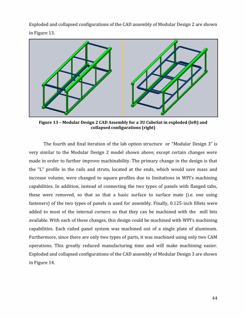
44
Exploded and collapsed configurations of the CAD assembly of Modular Design 2 are shown
in Figure 13.
Figure 13 – Modular Design 2 CAD Assembly for a 3U CubeSat in exploded (left) and collapsed configurations (right)
The fourth and final iteration of the lab option structure or “Modular Design 3” is
very similar to the Modular Design 2 model shown above, except certain changes were
made in order to further improve machinability. The primary change in the design is that
the “L” profile in the rails and struts, located at the ends, which would save mass and
increase volume, were changed to square profiles due to limitations in WPI’s machining
capabilities. In addition, instead of connecting the two types of panels with flanged tabs,
these were removed, so that so that a basic surface to surface mate (i.e. one using
fasteners) of the two types of panels is used for assembly. Finally, 0.125-inch fillets were
added to most of the internal corners so that they can be machined with the mill bits
available. With each of these changes, this design could be machined with WPI’s machining
capabilities. Each railed panel system was machined out of a single plate of aluminum.
Furthermore, since there are only two types of parts, it was machined using only two CAM
operations. This greatly reduced manufacturing time and will make machining easier.
Exploded and collapsed configurations of the CAD assembly of Modular Design 3 are shown
in Figure 14.

45
Figure 14 – 3nd Modular CAD Assembly for a 3U CubeSat in collapsed (left) and exploded configurations (right)
CAD assembly models have also been created which serve as schematics
representing the placement of the individual hardware components within the CubeSat.
The first iteration of the schematic assembly of “Lab Assembly 1” is uses modular design 1
to house the subsystem components. Exploded and collapsed configurations of Lab
Assembly 1 are shown in Figure 23. This assembly highlights only one possible
configuration of the components in the CubeSat, the final placement of components in the
Lab Option may vary based on center of mass, passive thermal heating, and
electromagnetic interference considerations. In this model, the modularity of the design is
taken advantage of in fastening the propulsion system to the satellite. As shown in Figure
15, the outside wall, to which the propellant tank is attached, has two struts which have
been added to ensure reinforcement for a rigid attachment. After examining this assembly,
it was apparent that based on the current selection of components, there is additional
space in the satellite that could accommodate an additional payload or a larger propulsion
subsystem.

46
Figure 15 – CAD Assembly model of Lab Assembly 1 in exploded (left) and collapsed configurations (right)
The second and final configuration assembly (Lab Assembly 2) uses the structure of
Modular Design 3 and will be used as a guide for assembling components into the
machined structure. The exterior walls in this assembly are slightly thicker (1.5 mm) than
in Lab Assembly 1, which is due to only certain aluminum panel thicknesses being readily
available. This will make the Lab Option CubeSat slightly heavier, but it will better be able
to support the loading of components mounted directly to the walls. In Lab Assembly 2,

47
more attention is given to the specifics of the arrangement of each of the components. Also
in this model, the circuit boards for the battery, PMAD, and OBC were assembled into a
circuit stack, which is sandwiched between two of the side walls allowing enough room for
the check valve. One of the side walls of Lab Assembly 2does not include any mounting
holes so that it can easily be removed for access to the inside of the CubeSat. Exploded and
collapsed configurations of Lab Assembly 2 are shown in Figure 16.
Figure 16 – CAD Assembly model of Lab Assembly 2 in exploded (left) and collapsed configurations (right)
Concerning the machining and assembly of the CubeSat, the CAD models of the CubeSat
were input into the CAM software, ESPRIT, in order to create machine processes to

48
machine the different parts using CNC machines. As for the Lab Option, Lab Assembly 2 was
chosen to become the final lab design. The primary structure of this design is made up of
two part types: the railed panel and the connecting panel. The part files for the final CAD
models for Lab Assembly 2 were then inputted into ESPRIT in order to create machine
processes. A total of three CAM operation files were created for each of the part types. The
CAM operation files were then converted into numerical control (NC) code, which would be
used by the Haas Vertical Machining Center Toolroom Mill (TM-1) shown in Figure 17
below.
The TM-1 would then use the
machine code to operate its tool bits
and machine the part. Six tools have
been identified to create the tool list
for the machining of both panels: (1)
0.5-in End Mill, (2) 0.1875-in End
Mill, (3) 3-in Face Mill, (4) #2 Center
Drill, (5) 1.6-mm Drill - M2, and (6)
2.5-mm Drill - M3. Furthermore,
before actual machining of the parts
could begin, the raw Aluminum
6061-T6 material was prepared to the correct stock sizes using various band saws. An
example of a pocketing operation can be seen in Figure 17, with each part taking 70-100
minutes machining time each.
Figure 17 – Haas Vertical Machining Center
Toolroom Mill (TM-1) [51]

49
Figure 18 – Pocketing Operation [51]
Both railed and connecting panels have been machined completely, which can be seen in
Figure 19. The use of the TM-1 allows for precision machining with very low tolerances
needed for spacecraft construction.
Figure 19 – Completed Railed & Connecting Panels [51]
3.4 Lab Option vs. Flight Option
This paper presents two different design considerations: “Lab Option” and a “Flight
Option” CubeSat designs. The most time and consideration in this particular MQP were
dedicated to designing and building the Lab Option. This set of design choices, components,
and analysis, are specifically intended to satisfy the requirements of the CubeSat payload,

50
but are not space flight qualified. These Flight Option components can be assembled and
tested in a space environment simulator, but are not qualified for spaceflight. Some
components of the Lab Option were ordered and constructed.
The Flight Option design is intended for operational space flight. The Flight Option
component selections detailed in Chapter 5 will fully support the payload on orbit within
the mission parameters detailed in Section 4.1. Flight Option components were not
purchased during this project.

51
4 Lab Option Component Selection and
Analysis
The components specified below (for both flight option and lab option) were
selected based on specifications drawn from the mission requirements, payload
specifications, and CalPoly CubeSat regulations. All components for the Lab Option were
designed to fit within the physical dimensions of a standard CubeSat, to be consistent with
mission criteria, and to be within the budget of this WPI project. Although the Lab Option
components are not certified for space flight, they are based on the same specifications
which would be used for a CubeSat designed to be flown.
4.1 Spacecraft and Payload Requirements
The mission requirements presented here are based primarily on the CalPoly
specifications for a CubeSat designed to be deployed from their P-POD. Although the
payload for the WPI CubeSat is still not finalized, the assumptions used to generate payload
specifications are detailed below.
4.1.1 Orbit Specifications
The mission and payload for the project
were specified by the project advisors and
selected to represent a realistic set
of mission requirements. As specified in the
project requirements document [4] the CubeSat
will follow a circular orbit at an altitude of
680km and a period of 98.2 minutes, where the
argument of latitude is defined as
Eq 4.1
Element Value
Semimajor axis a (km) 7051
Eccentricity e 0.0
Inclination i (deg) 98.0
RAAN Ω (d g) 0.0
Argument of Latitude u (deg) 0 0
Table 6 – Orbital Characteristics

52
Table 6 details the orbit characteristics.
4.1.2 Scientific Payload
The scientific payload is the Argus 1000 IR Spectrometer, an infrared spectrometer
used to investigate greenhouse gases in the atmosphere [10]. Table 7 lists the technical
specifications of the Argus 1000 IR Spectrometer:
Argus 1000 Specifications
Type Grating spectrometer
Configuration Single aperture spectrometer
Field of View 0.15 viewing angle around centered camera bore-sight with 15mm fore-optics
Mass 230g
Dimensions 50mm x 45mm x 80mm
Operating Temperature -20C to +40C
Survival Temperature -25C to +55C
Detector 256 element InGaAs diode array with Peltier cooler (customized options available)
Optics Gold with IR glass and coatings
Electronics Microprocessor controlled 10 bit ADC with co-adding to 13 bit, 3.6-4.2V input rail 250mA-600mA (375 mA typical)
Operational Modes -Continuous Cycle, constant integration time
-Continuous cycle, adaptive exposure
Data Delivery Fixed length parity striped packets of single or co-added spectra with sequence number, temperature, array temperature and operating parameters
Interface Prime and redundant serial interfaces (RS232 protocol)
Integration Time 500 s to 4 s
Calibration Two-wavelength laser calibration
Handling Shipped by courier in ruggedized carrying case
Table 7 – Argus 1000 IR Spectrometer Specifications [52]
4.2 Power Component Selection and Analysis
The project’s scientific payload, the Argus 1000 IR Spectrometer, requires the power
subsystem to provide a continuous feed of 572mA (375mA typical) at 3.5-5.0V. The Power
Management and Distribution (PMAD) electronics will need to stabilize any current spikes
within 10ms of detection, and the power feed to the spectrometer must be switched on or
off as commanded by the computer based on the operations schedule. In addition, the

53
power system is expected to meet the power requirements of other subsystems including
propulsion, onboard computing, attitude control, and other sensors.
4.2.1 Solar Cells
As described in Section 2.2.1, solar cells will be the primary power source for the
CubeSat, and will be used to charge the battery for use during eclipse or in times of peak
power demand. Several factors influence the total power output of the solar cells: cell
placement (fixed on body vs. deployable array), cell orientation relative to the sun, solar
cell area, and any protective coatings on the cells.
The power density available from a solar cell will depend on the illumination (solar
constant) and the cell efficiency as shown in Eq 4.2.
Eq 4.2
where efficiency is defined as the percentage of the total energy absorbed by the solar cell
that is converted to electrical power (i.e. for a low-cost “hobby-shop” solar array).
Alternatively, if the mean voltage of the solar cell is multiplied by mean current, , then
the electrical power produced is given by:
where current is expressed in Amps and voltage in Volts. The power at beginning of life
(BOL) can then be determined, taking into account the inherent degradation Id and the
reduction in power output with increase in angle to the sun, (measured as the angle
between a vector normal to the solar cell and a vector extending from the solar cell to the
sun):
Eq 4.4
where is assumed to be (or ) efficiency as a nominal power loss due inherent
Eq 4.3

54
inefficiencies in a solar array power system. Eq 4.4 provides the power output of a solar
cell (just as in Eq 4.2 and Eq 4.3), but Eq 4.4 also accounts for the angle of the solar cell in
relation to the sun as well as system inefficiencies.
The Power at Beginning of Life can also be used to determine the output power
density per unit area
Eq 4.5
Eq 4.2 through Eq 4.5 can be manipulated to determine the area of solar cells
required to produce a given amount of power based on the efficiency, angle to the sun,
brand of solar cell, and solar cell area [7].
A variety of solar cell options were considered for use on the Lab and Flight options,
assuming the total cell area would occupy a 10 cm x 10 cm area (equivalent to one side of a
1U CubeSat). For the Lab Option, solar cells from SolarBotics (Calgary, Alberta, Canada) and
Solar World (Hillsboro, OR) were considered. As shown in Table 8, these solar cells are
affordable but they will not supply adequate power for our satellite unless significant
design changes are implemented (i.e. increasing the area of the solar cells either by
creating deployable arrays or covering more of the satellite body with cells).
Brand SolarBotics Solar World
Dimensions 3.7cm x 6.6cm square cells 9.525cm x 6.35cm square cells
Price $7.15-$11.00 per cell $7.95-$9.95 per cell
Voltage per Area 6.7V at 1.2285mA/cm2 0.5V at 13.2267mA/cm2
Peak Power Output
0.6191W at 97.68cm2 0.31W at 60.48cm2
Table 8 – Lab Option Solar Cell Comparison [53] and [54]
4.2.2 Batteries
Batteries will be used to provide the CubeSat’s energy storage for the duration of the
mission. Due to the maximum practical mission length for a CubeSat (shorter than 3 years),
the battery will only provide back-up power for periods of eclipse and peak power demand.

55
Typical CubeSat batteries provide either 3.3V or 5.0V. The scientific payload will require a
5.0V battery while the size of the satellite will limit the design to one secondary
(rechargeable) battery. When choosing components for the Lab and Flight Options, battery
storage capacity and total mission length were the highest weighted figures-of-merit to
ensure that the flight battery is designed to endure the number of charge/discharge cycles
required by the satellite while still providing adequate power.
Although time did not permit actual purchase and testing of a lab option battery, it
was determined that a 5.0V (approximately 1500 mA-hr) rechargeable Lithium Ion battery
would be the best option for lab testing, as it can provide a stable and reliable power source
and is easy to integrate with the selected battery charging circuitry.
4.2.3 Power Management and Distribution (PMAD)
An integrated PMAD module is produced by the Clyde Space Corporation specifically
for use on CubeSats. Clyde Space designs custom PMAD systems to integrate with specific
scientific instruments to be launched on CubeSats. This option is ideal for space flight
because the Clyde Space PMAD systems are specifically designed for flight aboard a
CubeSat. At over $2500, however, this option’s cost is prohibitive for the present project’s
lab option.
In order to closely simulate the operations of the CubeSat in a lab environment, it
was necessary to design and build a Power Management and Distribution system that could
simulate all the functions of a flight-option PMAD. This system had to be able to produce
power, condition power to the correct voltage and current for each device, and switch
devices on and off based on commands from the flight computer.
When the Lab Option is eventually completed, power will be provided first by “lab
option” solar cells illuminated by bulbs in a Space Environment Simulator (the large
vacuum chamber in WPI’s Higgins Labs for the purposes of this CubeSat). The DC power
from the solar cells will be used to charge the lab battery and potentially to power
individual components (although the cells do not provide enough power to support all
systems at once). Supplementary power will be provided through an umbilical attached to
a simple “lab bench” DC power supply connected in parallel with the batteries and solar
cells.
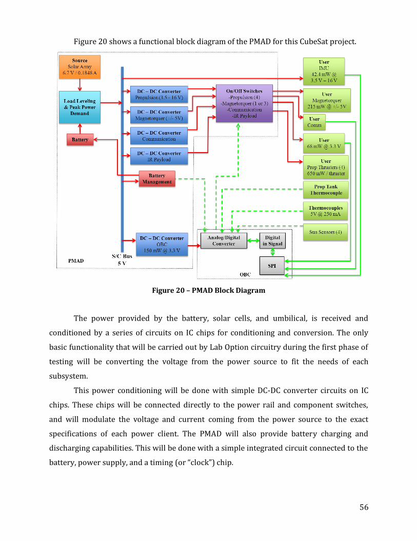
56
Figure 20 shows a functional block diagram of the PMAD for this CubeSat project.
Figure 20 – PMAD Block Diagram
The power provided by the battery, solar cells, and umbilical, is received and
conditioned by a series of circuits on IC chips for conditioning and conversion. The only
basic functionality that will be carried out by Lab Option circuitry during the first phase of
testing will be converting the voltage from the power source to fit the needs of each
subsystem.
This power conditioning will be done with simple DC-DC converter circuits on IC
chips. These chips will be connected directly to the power rail and component switches,
and will modulate the voltage and current coming from the power source to the exact
specifications of each power client. The PMAD will also provide battery charging and
discharging capabilities. This will be done with a simple integrated circuit connected to the
battery, power supply, and a timing (or “clock”) chip.

57
Finally, the PMAD will provide switching capabilities to turn each individual
component on and off. This capability will be particularly important in lab testing because
the solar cells cannot produce enough power to run all subsystems simultaneously. Each
individual subsystem will be switched on and off via a manual input (most likely via a
laboratory desktop computer) into the PMAD for the first phase of testing.
Function Component Specifications Notes
DC Conversion LT1054CN8#PBF-ND Boost/buck conversion,
3.5V-15V @ 100mA DC Conversion and
switching combined
on one IC Switching LT1054CN8#PBF-ND Simple high/low input
signal (@ 5V) for on/off
Battery Charging LM3622MX-4.1-ND Li-ION Battery, 24V max Requires additional
IC diode and timer
Table 9 – Lab Option Power Subsystem Components [55]
The parts listed in Table 1 were selected for compatibility with each other and to
fulfill the power requirements of the other subsystems presented in this report. Although
the parts were ordered and received, time did not allow for any significant testing. All parts
were ordered from Digi-Key (Thief River Falls, MN).
4.3 Propulsion System Selection & Analysis
Upon completion of the literature review (Section 2.3) performed by the Propulsion
Subsystem, in conjunction with the constraints set forth by the CubeSat Design
Specifications document and WPI project scope, a cold gas propulsion system was the most
feasible system to implement [22]. The propulsion system for Lab Option 1 is strictly a cold
gas system. Two Lab Options were considered due to the restriction placed on pressure
vessel by the CubeSat Specifications Document resulting in concerns of propellant storage
limitations. The propellant is air compressed to approximately .
Compressed air was chosen because of its ease of use, safety and cost. Compressed air was
readily available in the on-campus laboratory where all propulsion system testing will take
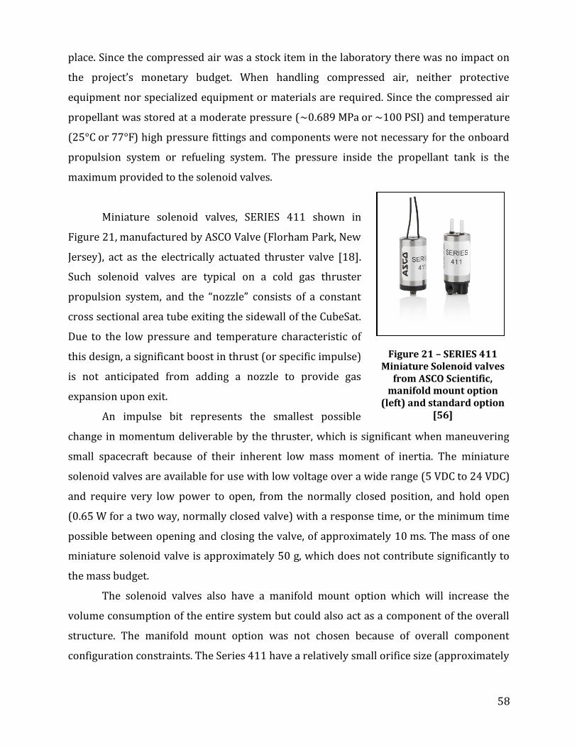
58
place. Since the compressed air was a stock item in the laboratory there was no impact on
the project’s monetary budget. When handling compressed air, neither protective
equipment nor specialized equipment or materials are required. Since the compressed air
propellant was stored at a moderate pressure ( ) and temperature
( ) high pressure fittings and components were not necessary for the onboard
propulsion system or refueling system. The pressure inside the propellant tank is the
maximum provided to the solenoid valves.
Miniature solenoid valves, SERIES 411 shown in
Figure 21, manufactured by ASCO Valve (Florham Park, New
Jersey), act as the electrically actuated thruster valve [18].
Such solenoid valves are typical on a cold gas thruster
propulsion system, and the “nozzle” consists of a constant
cross sectional area tube exiting the sidewall of the CubeSat.
Due to the low pressure and temperature characteristic of
this design, a significant boost in thrust (or specific impulse)
is not anticipated from adding a nozzle to provide gas
expansion upon exit.
An impulse bit represents the smallest possible
change in momentum deliverable by the thruster, which is significant when maneuvering
small spacecraft because of their inherent low mass moment of inertia. The miniature
solenoid valves are available for use with low voltage over a wide range ( )
and require very low power to open, from the normally closed position, and hold open
( for a two way, normally closed valve) with a response time, or the minimum time
possible between opening and closing the valve, of approximately . The mass of one
miniature solenoid valve is approximately 50 g, which does not contribute significantly to
the mass budget.
The solenoid valves also have a manifold mount option which will increase the
volume consumption of the entire system but could also act as a component of the overall
structure. The manifold mount option was not chosen because of overall component
configuration constraints. The Series 411 have a relatively small orifice size (approximately
Figure 21 – SERIES 411 Miniature Solenoid valves
from ASCO Scientific, manifold mount option
(left) and standard option [56]

59
0.0125 in), which should be satisfactory for this application. In the Lab Option 1, propellant
will be filtered prior to entering the propulsion system, therefore filters were not necessary
onboard the CubeSat.
A thermocouple will be located on the propellant tank to monitor fuel temperature,
which will be used to determine fuel pressure through calculation performed by the On
Board Computer (OBC), see Figure 22. The pressure of the fuel will be used by the OBC in
an algorithm to determine the “burn time” of the thrusters for a given maneuver. The
surface mounted thermocouple is not ideal and inaccuracy in the actual temperature of the
fuel is expected and will be compensated for in analysis and algorithms.
The propellant tank is refillable using a check valve to regulate the flow direction
and seal one end of the propellant tank. A SolidWorks model of the Lab Option 1 propulsion
system is shown in Figure 22. The propellant tank is attached to the sidewall with custom
bracketing to minimize the propellant tank and lines from experiencing excessive
vibrations and also to prevent the lines from supporting all the weight of the tank. The
check valve, located at the bottom of the figure, will also have a custom mounting bracket
to minimize vibrations and to prevent any damage to the propellant lines while using a
wrench to attach/remove fill lines. The filling process consists of removing the side wall at
the end of the CubeSat and attaching a fill line (connected to a supply tank in the
laboratory) to the check valve via a secure tube fitting connection. The propellant lines
consist of stainless steel tubing and will connect to the propellant tank, solenoid
valves and check valve with off-the-shelf tube fittings.

60
The Lab Option 2 propulsion system was
essentially a hybrid of a liquefied gas thruster
system and a cold gas thruster system. Lab Option 2
was not constructed but considered as a laboratory
option due to financial (component and propellant
cost), safety (propellant handling and storage) and
time to manufacture constraints.
Using liquid propellant such as butane or
alcohol contained in a single tank would allow the
liquid and vapor to reach equilibrium. The vapors
would not be heated in any way and the vapor
pressure inside the propellant tank would be the
maximum pressure achievable by the system.
Solenoid valves, identical to those considered for
Lab Option 1, act as the thruster valves. A nozzle
would not be implemented and the same fittings
and tubing would be used. The thermocouple
mounted to the propellant tank would provide the
fuel properties for the OBC. The temperature of the
fuel in this option is more critical because it will
determine the vapor pressure, therefore an accurate fuel temperature is essential and more
thermocouple mounting options may need to be considered, such as a probe inserted
directly into the tank. Since the probe, either inserted into an end or through the sidewall of
the propellant tank, would measure the temperature of the gas directly, rather than
through the tank wall, it will provide a much more accurate gas temperature measurement.
The propellant tank will only be storing gas at a maximum internal pressure of
(0.12159 MPa), as required by CubeSat Specifications Document [4]. The tank would have
been manufactured on the WPI campus from Plexiglas or Lexan. Because the CubeSat will
be mounted to a fixture limited to rotation about the vertical axis during testing, propellant
displacement inside the tank should not be an issue.
Figure 22 – Lab Option 1 SolidWorks model

61
4.3.1 Propulsion Analysis
The first step towards any analysis of the propulsion system capability involves
calculating attainable values of , which can then be used to calculate possible orbital
maneuvers. This was done using the rocket equation:
(
) Eq 4.6
Where is the gravitational acceleration constant at sea-level (9.81 m/s2), Isp is the
specific impulse (approximately 60s), typical for cold gas thrusters, and m0 and mf are the
initial and final masses of the CubeSat, respectively. Calculations were carried out for
varying ratios of propellant mass to overall mass, with a realistic value close to or
even lower, the results of which can be seen in Table 10.
mp/m0 ∆V(m/s)
10% 62.02
25% 169.33
50% 407.99
75% 815.97
Table 10 – ∆V calculations for varying mass ratios.
4.3.2 Orbital Maneuvers
Having found the achievable s, these values can then be used to calculate orbital
maneuvers which may be performed by the CubeSat. The two orbital maneuvers
considered in this analysis were orbit raising and inclination change. Orbit raising would
involve raising the initially circular orbit of the CubeSat to a higher circular orbit via a
Hohmann Transfer. A Hohmann Transfer requires two engine firings, one to put the
CubeSat on an elliptical “transfer” orbit, the second to re-circularize the CubeSat’s orbit
once it has reached the desired altitude. The equation for finding the necessary to
perform a Hohmann Transfer in terms of altitude change ( ) and initial radius ( is
provided below [8], where is the standard gravitational parameter of Earth
(
)

62
√ (
) √
√
√
(
) Eq 4.7
The second orbital maneuver considered was an orbital inclination change. The ∆V
required for an inclination change was found using Eq 4.8 below:
(
) Eq 4.8
√
Eq 4.9
where is the initial velocity of the CubeSat in its circular orbit, found to be 7519m/s using
Eq 4.9, where r is the radius of orbit (roughly 7050km, or an altitude of 700 km) and is the
inclination change. The changes in altitude and orbital inclination are plotted in Figure 23
as a function of propellant mass ratio.
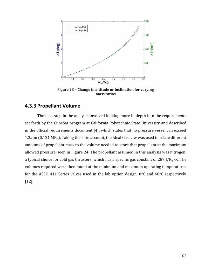
63
Figure 23 – Change in altitude or inclination for varying mass ratios
4.3.3 Propellant Volume
The next step in the analysis involved looking more in depth into the requirements
set forth by the CubeSat program at California Polytechnic State University and described
in the official requirements document [4], which states that no pressure vessel can exceed
1.2atm (0.121 MPa). Taking this into account, the Ideal Gas Law was used to relate different
amounts of propellant mass to the volume needed to store that propellant at the maximum
allowed pressure, seen in Figure 24. The propellant assumed in this analysis was nitrogen,
a typical choice for cold gas thrusters, which has a specific gas constant of 287 J/Kg-K. The
volumes required were then found at the minimum and maximum operating temperatures
for the ASCO 411 Series valves used in the lab option design, 0°C and 60°C respectively
[12].

64
Figure 24 – Propellant Mass vs. Volume
Assuming a generous propellant volume to overall volume ratio of 50%, the
propellant mass comes out to be roughly 0.75 g at the minimum operating temperature for
a 1U CubeSat. This corresponds to a negligible ΔV of 0.332 m/s. For the same volume ratio
with a 3U CubeSat, the propellant mass is roughly 2.5 g, with a corresponding ΔV of 0.368
m/s.
Given the possibility of applying for a waiver to go beyond the1.2 atm limit in mind,
the Ideal Gas Law was again used to find volume requirements for varying amounts of
propellant in a 1U CubeSat over a range of pressures much higher than the 1.2 atm limit.
This can be seen in Figure 25.
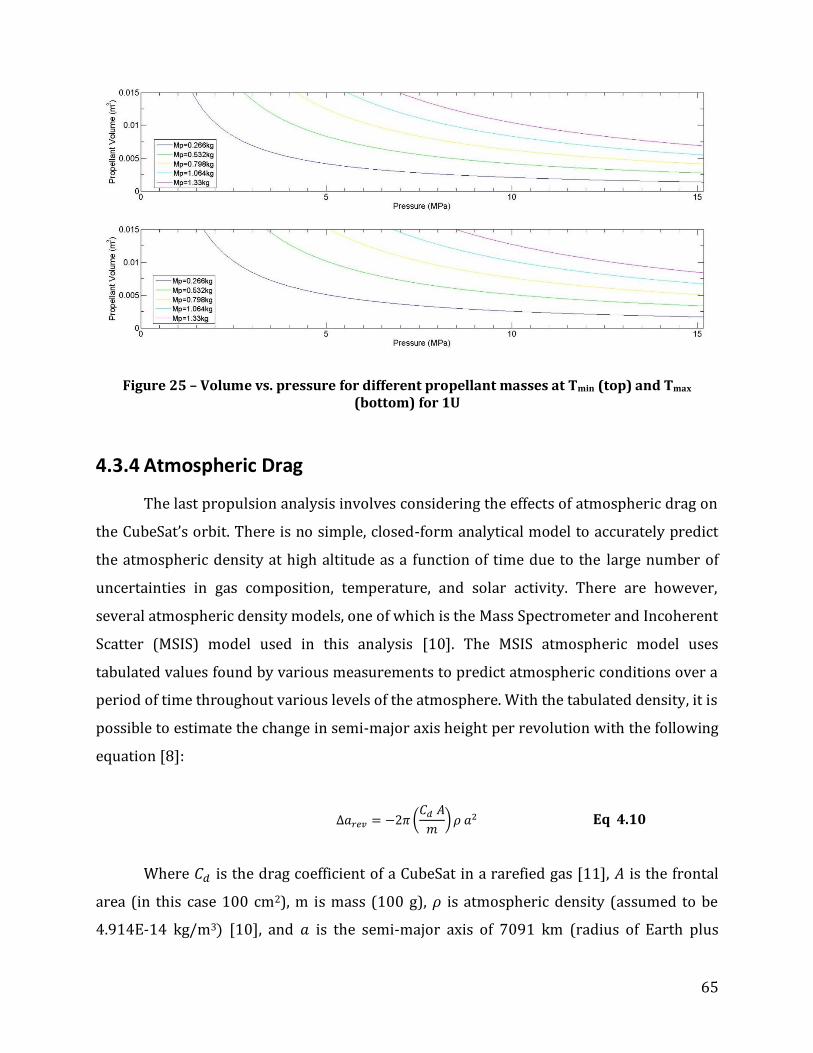
65
Figure 25 – Volume vs. pressure for different propellant masses at Tmin (top) and Tmax (bottom) for 1U
4.3.4 Atmospheric Drag
The last propulsion analysis involves considering the effects of atmospheric drag on
the CubeSat’s orbit. There is no simple, closed-form analytical model to accurately predict
the atmospheric density at high altitude as a function of time due to the large number of
uncertainties in gas composition, temperature, and solar activity. There are however,
several atmospheric density models, one of which is the Mass Spectrometer and Incoherent
Scatter (MSIS) model used in this analysis [10]. The MSIS atmospheric model uses
tabulated values found by various measurements to predict atmospheric conditions over a
period of time throughout various levels of the atmosphere. With the tabulated density, it is
possible to estimate the change in semi-major axis height per revolution with the following
equation [8]:
(
) Eq 4.10
Where is the drag coefficient of a CubeSat in a rarefied gas [11], is the frontal
area (in this case 100 cm2), m is mass (100 g), is atmospheric density (assumed to be
4.914E-14 kg/m3 [10], and is the semi-major axis of 7091 km (radius of Earth plus
66
altitude). For a 3U CubeSat, the values for drag will be the same as 1U due to the fact that all
parameters remain the same, except for the frontal area and mass which scale
proportionally to each other, (in other words; for a 3U CubeSat the frontal area becomes
three times that of the 1U and mass also becomes three times that of the 1U). This
calculation assumes that the CubeSat is orbiting with the largest frontal area perpendicular
to the flow direction, in other words, “sideways” as opposed to “end first”. With the above
parameters, the initial change in semi-major axis height per revolution was found to be
roughly 25 cm. However it is important to note that this is just a rough estimate, using an
average value for atmospheric density based off of the MSIS atmospheric model. It is also
noteworthy to add that this value does not remain constant. As the CubeSat descends with
every orbital revolution, the density will continue to increase, causing the loss in semi-
major axis altitude to grow exponentially until it finally reaches the point where the orbit
decays rapidly. This “lifetime” of the satellite can be estimated using Satellite Tool Kit
(STK), a software suite designed by Analytical Graphics, Inc, which allows mission planners
to simulate the orbit of a spacecraft, providing important information on the satellite’s
environment, ground tracks, and many other details vital to mission design [13]. Upon
completion of the lifetime calculation by STK, it was found that the CubeSat’s expected
lifetime will be approximately 60 years, which exceeds the required lifetime set forth by
the CubeSat’s mission.
4.4 Mechanical Structures Design Selection & Analysis
Analysis
In order to properly design and construct a CubeSat, analysis must be performed on
CubeSat models. Examples of such “virtual tests” can include a manufacturability test,
stress analysis test, and dynamic response analysis test, among others. Performing such
studies on the models helps to optimize parts for improved performance in the intended
environment and provides a low-cost solution to testing, in which the computer-based
model is tested rather than machining the actual CubeSat and testing it multiple times,
essentially eliminating multiple field tests. Furthermore, parts can be optimized for mass

67
by performing stress analysis tests on the models to determine the minimum mass needed
to have adequate structural strength.
Before virtual stress analysis tests
can be performed on the CubeSat models,
it must first be known what types of force
loading the spacecraft will undergo from
initial transportation to end of operation.
For most spacecraft, including CubeSats,
the greatest force loading occurs during
launch. In order to accurately estimate the
loading on the WPI CubeSat during launch,
the typical launch loading of three frequently used launch vehicles for past CubeSats were
reviewed. The three launch vehicles reviewed are the Dnepr, the Eurockot, and the
Minotaur I [12]. The most frequently used launch vehicle is the Dnepr [12], which is a
Russian developed rocket that has been converted from an Intercontinental Ballistic
Missile (ICBM) [11]. The Eurockot is a launch vehicle from Russian commercial launch
provider Eurockot Launch Services and has been designed for launching satellites into low
earth orbit (LEO) [13]. The Minotaur I is an American commercial launch vehicle for small
satellites designed by Orbital Sciences Corporation [14]. The various types of launch
vehicle loading reviewed include longitudinal and lateral g-loading, as well as random and
harmonic vibration loading over different frequency ranges. With the load values acquired
for each of these launch vehicles, accurate vibration load testing can be performed and the
structure of the CubeSat can be optimized in order to withstand the greatest loading with
as little mass as possible. Table 12 lists the maximum lateral and longitudinal loads for each
of these three launch vehicles. Table 12 also shows when the maximum loading occurs
during ascent. As shown below, the highest overall loading occurs with the Dnepr launch
vehicle, so the WPI CubeSat flight option CubeSat will be designed to withstand similar
loading.
Property Name Value Units
Elastic Modulus 7.2e+010 N/m²
Poisson’s Ratio 0.33 –
Shear Modulus 2.69e+010 N/m²
Mass Density 2810 kg/m³
Tensile Strength 5.7e+008 N/m²
Yield Strength 5.05e+008 N/m²
Thermal Expansion Coefficient
2.4e-005 1/K
Thermal Conductivity 130 W/(m∙K)
Specific Heat 960 J/(kg∙K)
Table 11 – Properties of Aluminum 7075 [15]

68
Launch Vehicle
Max. Longitudinal G- Loading and Time
Max Lateral G- Loading and Time
Dnepr
[11] + 8.3 g’s at 2nd Stage Burn
0.8 g’s after LV exit from transport launch canister
Eurockot
[13] +8.1 g’s at Stage I engine
Cut-Off +/- 0.9 g’s due to max.
dynamic pressure
Minotaur I
[14] +6.6 g’s 2nd Stage Ignition +1.6 g’s at Liftoff
Table 12 – Typical Launch Loads of Past CubeSat Launch Vehicles [14]
Once all the launch loads and characteristics are known, the structure can be tested
using various simulation modeling tools. SolidWorks offers many modules to test the
manufacturability and perform structural analysis of any models or assemblies created. In
turn, this helps to optimize parts or assemblies to make them more efficient for use in the
environments for which they are designed to operate. Manufacturability tests aid in
determining how easy-to-machine a part will be so users can see how much time, effort,
and cost parts will take to make. This allows the users to make educated decisions with
regards to what designs and materials they want to use for the end product. Structural
analysis tests aid in determining if assemblies can withstand the launch and flight
characteristics specified. Lastly, simulation analysis aids in providing testing for different
static and dynamic environments to model how the assembly will perform under adverse
conditions.
To perform stress analysis, the SimulationXpress Analysis Wizard module inside
SolidWorks was used to determine a model’s performance under static loads. The
SimulationXpress determines the von Mises Stress4, displacement, deformation, and factor
of safety of a module and provides results in graphical form. Using simulated restraints or
fixtures, static loads such as forces or pressures can be applied to the model allowing for
analysis under different stress conditions. This allows the designer to view which areas in
the model are critical regions with regards to stress as well as view which areas of the
model are being deformed by the stress. Depending on the factor of safety needed for the
4 von Mises Stress – used to predict yielding of materials under any loading condition from results of simple uniaxial tensile tests
69
model, the designer can optimize the model by adjusting different parameters to create
greater performance under stress while minimizing mass.
The DFMXpress module inside SolidWorks can be used to validate the
manufacturability of the model by identifying design areas that might cause problems in
fabrication or areas that might increase production costs. Specific examples of such
problems are sharp interior corners, which are difficult to machine due to radii of the
toolbits used to mill the material. Other areas of concern are stress concentrations that will
result from machining very thin and long parts, since the toolbit will tend to deform the
part which might cause failure and fractures. Using this module helped in ensuring the final
Lab Option design could be machined here at WPI.
SolidWorks also offers a suite of Simulation modules: Linear Static Analysis,
Frequency Analysis, Dynamic Analysis, Linearized Buckling Analysis, Thermal Analysis,
Nonlinear Static Analysis, Drop Test Analysis, Fatigue Analysis, as well as Beam & Trusses
Analysis. SolidWorks testing and analysis allows the creation of an optimal CubeSat model
before machining an actual CubeSat structure.

70
Figure 26 – CubeSat Structural Stress Analysis (von Mises Stress, Displacement, Deformation (top to bottom)
The results of the structural stress analysis are shown in Figure 26 were generated

71
using the SimulationXpress Analysis Wizard module inside SolidWorks. A 1U Monoblock
CubeSat structure was given 1 g static loads applied to the bottom rails directed upwards in
order to simulate a launch environment. Three tests: the von Mises Stress, displacement,
and deformation were performed and results used to investigate the structural integrity of
the CS structure under launch environment conditions.

72
5 Flight Option Component Selection and
Analysis
Although time and budget did not allow for purchase, construction, or testing of any
Flight Option items, extensive research was performed to select ideal flight components for
a space-ready CubeSat. These components were selected to perform the prescribed mission
with the payload listed in Section 4.1.2, and to work with each other.
5.1 Power Subsystem
When selecting the power components (solar panels, battery, and PMAD) for the
Flight Option CubeSat, two companies were considered: Clyde Space (Glasgow, Scotland)
and CubeSat Kit (San Francisco, CO). After careful deliberation, Clyde Space was selected as
the supplier for the Flight Option CubeSat components for several reasons.
Most importantly, Clyde Space's reliability and experience are unparalleled. Clyde
Space has built and provided power system and solar panel components for the SOHLA-2
Panel ExTension SATellite (PETSAT); solar panels for the SumbandilaSat Satellite (which
were constructed, tested, and shipped in a record 4 weeks) [4]; and a 1U EPS, two batteries,
and solar panels for the PARADIGM UT CubeSat. In addition, Clyde Space supplies both off-
the-shelf components, made in bulk, that conform to the CubeSat standards laid out by
CalPoly, as well as custom made products that can be made to fit specific mission
requirements. Finally, all of Clyde Space's components are space-ready and have
undergone extensive testing. All Clyde Space components are compatible with one another,
making it very easy to fully integrate a complete power system into a CubeSat.
The components selected for the Flight Option are all provided by Clyde Space, and
can be ordered by the customer to perfectly match any mission parameters and
specifications. These components, described in the following subsections, are clearly very
expensive, but are the “industry standard” for flight-ready CubeSat components.
73
5.1.1 Flight Option Solar Cells
Clyde Space specializes in making custom CubeSat space components. Clyde Space
creates custom 3U side solar panels that can incorporate seven large-area, triple junction,
solar cells from Spectrolab for £3,750 ($6,120) [7]. It was determined that Clyde Space
actually orders their solar cells from EMCORE and Spectrolab, and simply custom fits these
cells to satellites.
The 29.5% efficiency NeXt Triple Junction (XTJ) Solar Cells from Spectrolab, which
are constructed with a germanium substrate and cell structure of GaInP2/GaAs/Ge, were
selected for the flight option. These cells will cover an area of 271.825 cm2, and at full
illumination, will produce 10.962W with 2.33V at 17.32mA/cm2. The amount of power
these cells produce is far beyond the power requirements of the satellite payload and
subsystems, as well as power needed for battery charging. These cells will still provide the
satellite with enough power even including inefficiencies in the system or cell damage after
launch. [9]
5.1.2 Flight Option Battery
Clyde Space produces a Lithium-Polymer battery for £950 ($1550). This battery has
an energy density of 120-150Wh/kg, with a capacity of 1.25Ah at 8.2V for 10Whr.
Moreover, the battery can operate for more than a year in LEO with over 5,000
charge/discharge cycles, which, like the solar cells, far exceeds the operational
requirements of the CubeSat. [9]
5.1.3 Flight Option PMAD
Called an EPS (Electric Power System) by Clyde Space, the PMAD is specifically
designed to integrate Clyde Space solar panels and batteries, making it an obvious choice
for selection, priced at £2,600 ($4,240). Standard operating functions of the PMAD include
load-leveling between the solar panels and battery, battery under-voltage and over-current
protection, and max solar-panel tracking [37].

74
5.2 Propulsion Subsystem
Several options for flight-ready propulsion systems were considered for this
CubeSat, and are detailed below.
5.2.1 Flight Option
The propulsion Flight Option recommendations are divided into two categories,
Primary and Auxiliary propulsion. The Primary propulsion recommendation is the Micro
Propulsion System (MiPS) manufactured by VACCO as described in Section 2.4.4. The MiPS
is designed specifically for use onboard CubeSats and meets the volume and mass
constraints inherent to a CubeSat. The MiPS offers high propellant storage mass with a low
volume penalty since the propellant is stored as a liquid. The system is manufactured using
patented ChEMS technology which allows plumbing connections to be avoided and a robust
titanium design. The design also includes redundant valves to protect against leakage and
does not include any sliding parts, which increases system reliability. The size of the
propellant tank can be increased as needed to store more propellant and is compatible
with a number of propellant types such as Nitrous Oxide (N2O). As part of the Flight Option
recommendation, the MiPS would only be used for primary propulsion (i.e. orbit raising or
shaping) although it offers auxiliary propulsive capabilities. This is to allow for redundancy
in auxiliary propulsion and to demonstrate the MiPS capabilities for orbit raising, which
was not a requirement for the scientific payload.
It is recommended that four thruster couples (eight thrusters total) be used for auxiliary
propulsion. Moog (model No. 58E142) thrusters were developed for the Pluto Fast Flyby
mission and considered for the Dawgstar, a detailed description is provided in Section
2.3.5. The size (diameter 14mm, length 20mm) and mass (0.016 kg) of the thrusters will
allow for simple integration into the CubeSat and a relatively low mass penalty. The
thrusters are compatible with most cold gas propellant options and can be custom ordered.

75
6 Results & Conclusions
6.1 Power Conclusions
Although this report only provided a preliminary investigation into the lab and flight
option systems for a CubeSat, it was possible to draw conclusions based on the research
and system integration described above.
6.1.1 Solar Cells
It should be noted that solar cell area can be adjusted depending upon the size of the
satellite (either 1U, 2U, or 3U), or if the decision is made to use some form of deployable
array. Additionally, due to the significant performance variations between the Flight and
Lab Option solar cells, testing with the Lab Option will most likely need to include a power
umbilical during testing to simulate power level provided by the Flight Option solar cells.
Otherwise, significant design changes would need to take place in order for the Lab Option
to adequately model our Flight Option.
6.1.2 Batteries
Battery options were not rigorously investigated as a part of the lab option research
in this report, but from the small amount of research above, it is clear that Li-ION batteries
will be the best choice for lab testing of the CubeSat, as his type of battery provides
sufficient power (approx.. 1500 mA-hr) and the battery charging circuitry for Li-ION
batteries is relatively simple. A prefabricated and integrated battery pack from a space-
manufacturing corporation (Clyde Space or similar) will be ideal for the flight option,
primarily because it is designed to integrate with the other components and provides a
relatively high power density and cycle life.

76
6.1.3 PMAD
The currently proposed lab-option PMAD will cost approximately $180-250 and will
require an external power umbilical to simulate the power that will be provided by the
flight-option solar cells (lab-option solar cells are not capable of producing enough power).
The lab-option PMAD will be developed to the breadboard level (in this MQP) and its
components eventually integrated into the lab test system(in a future MQP) to support all
other components of the CubeSat lab test.
6.2 Propulsion Conclusions
Performing even these fairly basic analyses has led to important conclusions that
will help facilitate the design of the CubeSat’s propulsion system. Due to the strict volume
constraints in a satellite, it appears that the limiting factor for the
effectiveness of this propulsion system will be the limit for any pressure vessels on
board. At this pressure, the mass of any gaseous propellant will be insufficient to perform
any significant orbit raising maneuvers or inclination changes. However, it may be possible
that this amount of propellant can be used to ensure the CubeSat does not exceed the
orbital lifetime limit of twenty-five years. This result has also led to investigation of other
forms of propellant such as liquid propellant, where the pressure would be the vapor
pressure of the liquid (much lower than the pressure of compressed (non-vapor) gas in the
conventional cold gas system). This would allow for the storage of much more propellant,
while still staying below the pressure limit of 1.2 atm.
Information regarding the sensitivity of the scientific payload with respect to
altitude is needed before a decision can be made as to whether or not drag’s effects on the
CubeSat’s orbit are completely negligible. More analysis should also be done on gaining a
better understanding of what the atmospheric density at time of launch will be. This could
not be done directly using the online MSIS model, as it has information only up to June,
2010. However, given the periodic nature of the sun’s activity, it is possible to look back
into the past at a point that had similar solar activity as the expected launch date.

77
7 Recommendations
Through research, investigation, development, and testing of multiple CubeSat
subsystems, the following recommendations are made for the future of this project.
7.1 Power Recommendations
The next logical step in designing the power subsystem for this CubeSat is to
breadboard and test the lab option circuitry. Although time did not allow for these circuits
to be built, they were fully designed and specified in this report, and are ready to be
assembled and lab-tested.
Another area of Power Management that requires attention is the function of Load
Leveling. This investigation of the capability to prevent power spikes and damage to flight
hardware due to transient currents is critical to mission success, but was unfortunately
beyond the scope of this report.
7.2 Propulsion Recommendations
To continue this project, the Lab Option propulsion system should be assembled and
tested to determine the feasibility of performing an attitude control maneuver using a cold
gas system. The propulsion subsystem team should work in collaboration with the
structures subsystem team to develop a test fixture to support the CubeSat during testing
and allow for as unrestricted motion as possible. If significant torques due to friction or
other external forces cannot be avoided they should be accounted for in thrust calculations.
Development of an algorithm to be used by the OBC for required valve open time will
require the estimation of a thrust coefficient. The thrust coefficient is required to relate the
chamber pressure to thrust which will determine attitude control maneuver parameters
such as valve open time.

78
7.3 Mechanical Structures Recommendations
For the lab option CubeSat, it is recommended that the structure be assembled and
all available subsystem components that are necessary to operate the cold gas propulsion
system be configured into the satellite in a manner similar to that of Modular Design 3.
After the Lab Option CubeSat is built, it is recommended that a test stand structure be built
to be used in the vacuum chamber for testing the Lab Option propulsion capabilities. A
schematic CAD model of a possible design for 1-axis test fixture is shown in Figure 27. The
test stand consists of a base which will attach to connecting adapters in the vacuum
chamber. There is a sliding bar attached to the base which could be used to adapt the test
stand to fit 1U, 2U, and 3U CubeSat sizes. There are also two adaptor plates in which the rail
ends of the CubeSat are inserted into. Attached to these adaptor plates are low friction
bearings in order to allow for relatively unperturbed rotation during testing.
Figure 27 – Schematic CAD model of test stand fixture in close-up (left) and configured in the vacuum chamber (right)

79
For the Flight Option CubeSat, it is recommended that a monolithic design such as
Monoblock Design 1 be used for the primary structure. This type of design requires the
least amount of assembly for the structure, which can significantly reduce the overall
weight. As previously stated, WPI’s machining capabilities cannot support the complex
design of a monolithic structure, so the machining will have to either be outsourced to
more capable facilities, or a prefabricated CubeSat structure will have to be purchased from
a specialized company such as ISIS or Pumpkin. It is assumed that the development of the
Flight Option will involve a sufficient budget to accommodate the high expenses associated
with obtaining an optimal CubeSat structure.
A second iteration of the
monoblock design 1 has been created
(monoblock design 2) which has a similar
appearance in structure to the CubeSat Kit
model in that the walls consist of a cross
lattice design in order to optimize mass
and structural integrity. Unlike the Lab
Option models, monoblock design 1 does
not use exterior paneling as part of the
structure. Instead, the substrate that the
solar cells are mounted to can act as the
exterior walls of the CubeSat. In addition,
thin aluminum walls can be mounted on
the outside for thermal and environmental
protection if necessary. A CAD model of
Monoblock Design 2 is shown in Figure 28.
The model shown contains all the
recommended components from each of
the subsystems.
Figure 28 – CAD Assembly monoblock design with subsystem components configured
inside

80
8 References
1. Mueller, Hofer, Parker, and Ziemer, “Survey of Propulsion Options for Cubesats”, 57th
JANNAF Propulsion Meeting, May 3-7, 2010, Colorado Springs, CO. JANNAF-1425.
2. Rysanek, F. , Hartmann, J., Schein, J., and Binder, R., Paper SSC02-I-2, 16th Annual
AIAA/ISU Conference on Small Satellites, Logan, UT, 2002.
3. VACCO.com [homepage on the Internet]. VACCO Industries Inc.: South El Monte,
California; 2005 [Copyright 2005; cited 6 October 2010]. Available from:
http://www.vacco.com/vacco/pdfs/mips2112.pdf
4. Cubesat.org [homepage on the Internet]. Cubesat [updated 02 September 2010; cited 6
October 2010]. Available from: http://cubesat.org/images/developers/cds_rev12.pdf
5. Airpower.au.af.mil/home.htm [homepage on the Internet]. Air University; 2003
[updated 14 October 2003; cited 6 October 2010]. Available from:
http://www.airpower.au.af.mil/airchronicles/aureview/1973/nov-dec/baty.html
6. Moore, G. Paper SSC10-III-8. 3D Printing and MEMS Propulsion for the RAMPART 2U
CUBESAT. In: 24th Annual AIAA/USU Conference on Small Satellites, Logan, UT, 2010.
7. Larson, Wiley J., & Wertz, James R. Spacecraft Mission Analysis and Design. 3rd ed.
Microcosm Press; 2009.
8. Gatsonis, NA. ME 2713 Formulary. 2008.
9. The CubeSat Program, Cal Poly SLO. CubeSat Design Specification Rev. 12. San Luis
Obispo: California Polytechnic State University; 2009.
10. Hedin, A. E. MSISE Model 1990 [homepage on the internet; cited 6 October 2010].
Available from: http://omniweb.gsfc.nasa.gov/vitmo/msis_vitmo.html.
11. Bonnema, A.R. Orbital Dynamics & Deployment.[homepage on the Internet; cited 6
October 2010]. Available from:
http://www.vki.ac.be/QB50/download/workshop/papers_18nov/bonnema.pdf.

81
12. Alminde, L., Bisgaard, M., Vinther, D., Viscor, T., & Østergard, K. Z. (2003). THE AAU-
CUBESAT STUDENT SATELLITE. Retrieved October 3, 2010, from control.auc.dk:
http://www.control.auc.dk/~kzoe00/articles/cubesat.pdf
13. Cal Poly. (2009, August 1). http://www.cubesat.org/index.php/about-us/mission-
statement. Retrieved September 28, 2010, from cubesat.org:
http://www.cubesat.org/images/developers/cds_rev12.pdf
14. CubeSat. (2010). Mission Statement. Retrieved September 28, 2010, from
www.cubesat.org: http://www.cubesat.org/index.php/about-us/mission-statement
15. DTUsat. (2007). Structure. Retrieved October 3, 2010, from dtusat1.dtusat.dtu.dk:
http://dtusat1.dtusat.dtu.dk/group.php?c_gid=13
16. EPFL. (2009). SWISSCUBE. Retrieved October 3, 2010, from swisscube.epfl.ch:
http://swisscube.epfl.ch/
17. Heidt, H., Puig-Suari, J., Moore, A. S., Nakasuka, S., & Twiggs, R. J. (2000). 14th Annual
Small Satellite Conference. CubeSat: A new Generation of Picosatellites for Education
and Industry Low-Cost Space (p. 19). Utah: Utah State University.
18. ISIS. (2010). Innovative Solutions in Space. Retrieved September 30, 2010, from
isispace.nl:
http://www.isispace.nl/index.php?option=com_content&task=view&id=61&Itemid=68
19. Koji Nakaya; Kazuya Konoue; Hirotaka Sawada; Kyoichi Ui; Hideto Okada; Naoki
Miyashita. (2003). Tokyo Tech CubeSat: CUTE-I, Design & Development of Flight Model
and Future Plan. Retrieved October 4, 2010, from Iss.mes.titech.ac.jp:
http://lss.mes.titech.ac.jp/ssp/cubesat/paper/AIAA_TokyoTechCubeSat.pdf
20. Pumkin Inc. (2008). CubeSat Kit. Retrieved October 3, 2010, from cubesatkit.com:
http://www.cubesatkit.com/index.html
21. University of Toronto Institute of Aerospace Studies. (2004). CANX-1. Retrieved
October 4, 2010, from utias-sfl.net: http://www.utias-
sfl.net/nanosatellites/CanX1/CanX1System.html

82
22. C. Zakrzwski, S. Benson, J. Cassady, P. Sanneman. “Pulsed Plasma Thruster (PPT)
Validation Report”, NASA/GSFC, June 23, 2002.
23. Mars-space.co.uk [homepage on the Internet]. Mars Space Ltd. 2007-2010. Available
from: http://mars-space.co.uk/MicroPPT.aspx
24. Sutton, G., Biblarz, O., “Rocket Propulsion Elements”. New Jersey: 2010.
25. W. Andrew Hoskins, Michael J. Wilson, Michael J. Willey, Nicole J. Meckel, Mark
Campbell and Seung Chung. “PPT Development Efforts at Primex Aerospace Company”.
AIAA 99-2291.
26. Morash, D. H., and Strand, L., "Miniature Propulsion Componentes for the Pluto Fast
Flyby Spacecraft," 30th Joint, Propulsion Conference, June 1994.
27. Schein, J., Gerhan, A. Rysanek, F. Krishnan, M. “Vacuum Arc Thruster for CubeSat
Propulsion”. Alameda Applied Sciences Corporation, San Leandro, CA; University of
Illinois Urbana-Champaign, IL.
28. Ascovalve.com [Homepage on the internet]. ASCO Valve. Available from:
http://www.ascovalve.com/Applications/Products/MicroGeneralServicesData.aspx
29. McHarris, O., Signell P., “The Magnetic Field of a Moving Charge”. Michigan State
University. February 1, 2000.
30. Cassady, R. J., Hoskins, W. A., Campbell, M., Rayburn, C. “A Micro Pulsed Plasma Thruster
(PPT) for the “Dawgstar” Spacecraft”. 0-7803-5846-5/00 IEEE. 2000.
31. AAU CubeSat – University of Aalborg (Denmark). Available from: www.cubesat.auc.dk
32. University of Arizona CubeSat Program – SACRED. Available from:
en.wikipedia.org/wiki/SACRED.
33. CAPE CubeSat Project. Available from: http://ulcape.org/projects/cubesats/
34. LSS – Tokyo Institute of Technology. Available from:
http://lss.mes.titech.ac.jp/ssp/cute1.7/subsystem_eps_e.html

83
35. Clyde Space, Inc. (Glasgow, Scotland). http://www.clyde-space.com
36. CubeSat Kit (Pumpkin, Inc., San Francisco, CA). http://www.cubesatkit.com
37. Clyde Space, Inc., 3U CubeSat Solar Panels. http://www.clyde-
space.com/cubesat_shop/solar_panels/3u_solar_panels/64_3u-cubesat-side-solar-
panel
38. SpectroLab Solar Cells (The Boeing Company, Sylmar, CA).
www.spectrolab.com/solarcells.htm
39. Clyde Space, Inc., CubeSat Standalone Battery. http://www.clyde-
space.com/cubesat_shop/batteries/16_cubesat-standalone-battery
40. Clyde Space, Inc., 3U CubeSat EPS. www.clyde-space.com/cubesat_shop/eps/12_3u-
cubesat-eps
41. Alminde, L., Bisgaard, M., Vinther, D., Viscor, T., & Østergard, K. Z. (2003). THE AAU-
CUBESAT STUDENT SATELLITE. Retrieved October 3, 2010, from control.auc.dk:
http://www.control.auc.dk/~kzoe00/articles/cubesat.pdf
42. Cal Poly. (2009, August 1). http://www.cubesat.org/index.php/about-us/mission-
statement. Retrieved September 28, 2010, from cubesat.org:
http://www.cubesat.org/images/developers/cds_rev12.pdf
43. CubeSat. (2010). Mission Statement. Retrieved September 28, 2010, from
www.cubesat.org: http://www.cubesat.org/index.php/about-us/mission-statement
44. DTUsat. (2007). Structure. Retrieved October 3, 2010, from dtusat1.dtusat.dtu.dk:
http://dtusat1.dtusat.dtu.dk/group.php?c_gid=13
45. EPFL. (2009). SWISSCUBE. Retrieved October 3, 2010, from swisscube.epfl.ch:
http://swisscube.epfl.ch/
46. Heidt, H., Puig-Suari, J., Moore, A. S., Nakasuka, S., & Twiggs, R. J. (2000). 14th Annual
Small Satellite Conference. CubeSat: A new Generation of Picosatellite for Education and
Industry Low-Cost Space (p. 19). Utha: Utah State University.

84
47. ISIS. (2010). Inovative Solutions in Space. Retrieved September 30, 2010, from
isispace.nl:
http://www.isispace.nl/index.php?option=com_content&task=view&id=61&Itemid=68
48. Koji Nakaya; Kazuya Konoue; Hirotaka Sawada; Kyoichi Ui; Hideto Okada; Naoki
Miyashita. (2003). Tokyo Tech CubeSat: CUTE-I, Design & Development of Flight Model
and Future Plan. Retrieved October 4, 2010, from Iss.mes.titech.ac.jp:
http://lss.mes.titech.ac.jp/ssp/cubesat/paper/AIAA_TokyoTechCubeSat.pdf
49. Pumkin Inc. (2008). CubeSat Kit. Retrieved October 3, 2010, from cubesatkit.com:
http://www.cubesatkit.com/index.html
50. University of Toronto Institute of Aerospace Studies. (2004). CANX-1. Retrieved
October 4, 2010, from utias-sfl.net: http://www.utias-
sfl.net/nanosatellites/CanX1/CanX1System.html
51. Patel, Brijen. Photographed in the CNC machine labs at Worcester Polytechnic Institute
52. Khoth Technologies. Retrieved October 11, 2010 from
http://www.thoth.ca/Argus_specifications.htm
53. SolarBotics. Retrieved September 22, 2010 from
http://www.solarbotics.com/products/scc3766/resources/
54. Solar World. Retrieved September 25, 2010 from http://www.solarworld-
usa.com/solar-for-business-and-government/products-and-services/sunmodule-solar-
panels.aspx
55. DigiKey Corporation. Retrieved March 1, 201 from http://www.digikey.com
56. ASCO Valves. Retrieved April 14, 2011 from
http://www.ascovalve.com/Common/PDFFiles/Product/411_SeriesR1.pdf

85
Appendix A: Abbreviations and Variables 1U One Unit, or One Liter CubeSat
2U Two Unit, or Two Liter CubeSat
3U Three Unit, or Three Liter CubeSat
BOL Beginning of Life
Cal Poly California Polytechnic State University
CubeSat Cube Satellite
EOL End of Life
I Electrical Current [measured in Amperes unless otherwise specified]
Id Inherent Degradation
MQP Major Qualifying Project
OBC On-Board Computer
P0 Power Density
P01 Power Density
P02 Power Density
PBOL Power Density at Beginning of Life
P-POD Poly Picosatellite Orbital Deployer
PMAD Power Management and Distribution
PPT Pulsed Plasma Thrusters
SEG System Engineering Group
V Volts
W Watts
WPI Worcester Polytechnic Institute

86
Appendix B: CubeSat Design Specifications5
5 Official CubeSat specifications from http://cubesat.org/images/developers/cds_rev12.pdf

87

88

89

90

91
Appendix C: CubeSat Database General Controls
Date Launch Vehicle
CubeSat Company Unit Attitude Actuators Attitude Sensors Magnetometer Information
Jun-
03 Eurockot
Aau Cubesat Aalborg Univ. 1 magnetorquers magnetometer (Honeywell components), sun sensor
Internal; 2 used in ADCS
DTUsat-1 Technical Univ. of
Denmark 1 magnetorquers
5 sun angle sensors, magnetometers
(Honeywell components)
Internal; Built from 4 Honeywell
sensors;
CanX-1 Univ. of Toronto Inst.
for Aero. Studies 1 magnetorquers GPS, magetometer (Honeywell)
Internal; Honeywell HMR 2300 3-axis; other subsystems shut down
during de-tumbling
Cute-1 Tokyo Institute of
Technology 1 ?
Piezoelectric Vibrating Gyros, 2-axis accel, CMOS camera Sun sensor
XI-IV University of Tokyo 1 permanent magnet,
libration damper ?
QuakeSat Stanford Univ. and
Quakefinder 3
permanent magnet, hysteresis rods
magnetometer (Honeywell components), sun sensor
External; 0.701 m deployable boom; ELF magnetometer
Oct-05
SSETI Express
Ncube-2 Norwegian Univ. of
Science and Tech. 1 magetorquers magnetometer Yes
XI-V Univ. of Tokyo 1 permanent magnet,
libration damper ?
UWE-1 Univ. of Wurzburg 1 ? Gyro
Feb-06
M-V-8 Cute-1.7+APD Tokyo Institute of
Technology 2 magnetorquers Gyro, sun sensors, manetometer Internal; Honeywell HMR 2300
Jul-06
Dnepr*
AeroCube-1 The Aerospace
Corporation 1 ? ?
CP1 Cal Poly, SLO 1 magnetorquers sun sensor
CP2 Cal Poly, SLO 1 magnetorquers magnetometers Internal; 2-axis magnetometer on
each side board
ICEcube-1 Cornell University 1 gravity gradient boom,
magnetorquers Magnetometer, GPS Yes
ICEcube-2 Cornell University 1 gravity gradient boom,
magnetorquers Magnetometer, GPS Yes
ION Universtiy of Illinios 2 magnetorquers, micro-vacuum arc thrusters
magnetometer,sun sensors Internal (as far as I can tell);
Honeywell HMC 2003
HAUSAT 1 Hankuk Aviation
University 1
permanent magnet,
hysteresis rods sun sensor, GPS
KUTEsat University of Kansas 1 magnetorquers magetometer, sun sensor Yes
MEROPE Montana State
University 1
permanent magnet,
hysteresis rods sun sensor (solar panels)
Ncube-1 Norwegian Univ. of Science and Tech.
1 magnetorquers magnetometer (Honeywell), sun sensor
(Solar panels) Yes
RINCON Univ. of Arizona 1 spin stabilized via
sunlight ?
SACRED Univ. of Arizona 1 spin stabilized via
sunlight ?
SEEDS Nihon University 1 ? Gyro, magnetometer Yes
Voyager Univ. of Hawaii 1 permanent magnet,
hysteresis rods
Dec-06
Minotaur 1 GeneSat-1 NASA Ames
Research Center 3
permanent magnet, hysteresis rods
Gyro, accelerometer
Apr-07
Dnepr
CSTB1 The Boeing
Company 1 magetorquers sun sensor, magnetometer Yes
AeroCube-2 The Aerospace
Corporation 1 ? ?
CP3 Cal Poly, SLO 1 magnetorquers magnetometer Internal/external; 2-axis
magnetometer on each side panel
CP4 Cal Poly, SLO 1 magnetorquers magnetometers Internal/external; 2-axis
magnetometer on each side panel
Libertad-1 Univ. Sergio
Arboleda 1 ? GPS
CAPE1 Univ. of Louisiana 1 permanent magnet,
hysteresis rods ?

92
General Controls
Date Launch Vehicle
CubeSat Company Unit Attitude Actuators Attitude Sensors Magnetometer Information
MAST Tethers Unlimited,
Inc. 3 ? GPS, magnetometer
Apr-08
PSLV-C9
COMPASS-1 Aachen Univ. of Applied Science
1 magnetorquers GPS, sun sensors, magnetometer Yes
Delfi-C3 Delft Univ. of Technology
3 permanent magnet,
hysteresis rods sun sensor (solar panels), wireless sun
sensor
SEEDS-2 Nihon Univ. 1 ? Gyro, magnetometer Yes
CanX-2 Univ. of Toronto Inst.
for Aero. Studies 3
magnetorquer, reaction wheel
sun sensors. Magetometers, camera (Earth, moon, stars sensor)
External; 20 cm extendable boom
AAUSAT-II Aalborg Univ. 1 magnetorquer,
momentum wheels Gyro, magnetometer
Cute-1.7+APDII
Tokyo Institute of Technology
2 magnetorquer Gyro, magnetometer, sun sensor
Aug-09
Falcon 1*
NanoSail-D NASA Marshall
Space Flight Center ?
Magnetic Passive stabilization**
?
PreSat NASA Ames
Research Center ? ? ?
May-09
Minotaur 1
AeroCube-3 The Aerospace
Corporation 1
permanent magnet, hysteresis rods
2-axis sun sensor, earth sensor
CP6 Cal Poly, SLO 1 magnetorquers magnetometers
Internal/external; 2-axis
magnetometer on each side panel; mission was to implement ADCS
with only magnetometers/magnetorquers
HawkSat Hawk institute for Space Sciences
1 ? ?
PharmaSat NASA Ames
Research Center 3 ? ?
Sep-09
PSLV-C14
BeeSat Berlin Institute of
Technology ?
micro wheels, magnetorquers
sun sensor, magnetometer (Honeywell), gyros
ITUpSAT Instanbul Technical
Univ. ? permanent magnet magnetometer, gyro, accelerometer
SwissCube Ecole Polytecnique
Federale de
Lausanna
? magnetorquers magnetometer, sun sensor, gyro
UWE-2 Univ. of Wurzburg ? permanent magnet GPS, sun sensors, magnetometer,
gyro, accelerometer
Jul-09
Endeavour
Aggiesat-2 Texas A&M Univ. 1 ? GPS Yes
BEVO 1 Univ. of Texas at
Austin 1 ? GPS
* Launch Vehicle
Failed
**premanent magnet and/or hysteresis rods