double punch test and abstract the tensile strength of...
TRANSCRIPT
•
DOUBLE PUNCH TEST AND
TENSILE STRENGTH OF CONCRETE
by
B. E. Trumbauer
W. F. Chen
ABSTRACT
The tensile strength of concrete can be determined by
several methods. The most popular method is the indirect
split-cylinder test. The formula for computing the tensile
strength of concrete for this test was first derived using
the theory of linear elasticity. An identical formula was
derived recently by Chen using the theory of perfect
plasticity. As a result a new tensile test, the double
punch test, was proposed.
The double punch test was examined experimentally,
and the effects of several parameters were investigated.
From the analysis of the results of the effects of the
different parameters, and from a comparison to the tensile
strength of concrete as determined by the split-cylinder
test, a method for performing the double punch test for
obtaining the tensile strength of concrete was proposed .

•
•
1 . Introduction
The tensile strength of concrete can be determined
by several methods. These methods include the direct
tension test, the flexural test, the ring test, and the
split-cylinder test.
Of all the methods introduced in recent years, the
split-cylinder test is probably the most common of the
tensile tests. The formula for computing the tensile
-1
strength of concrete from the split-cylinder test has been
obtained from the theory of linear elasticity [1]. More
recently, a plasticity treatment of this problem has been
given by Chen [2]. It has been found that the result
derived from the theories of perfect plasticity is identi
cal to that derived from the theories of linear elasticity.
The success in applying the theory of perfect plasticity
to this problem has led to the suggestion of a new alter
native test for concrete, the double punch test.
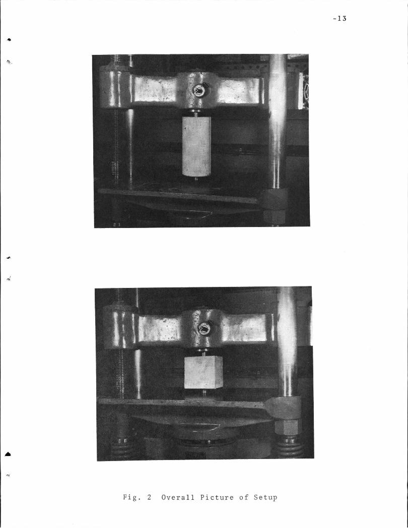
The double punch test has been proposed by Chen [3].
In this test, a concrete cylinder is placed vertically
between the loading platens of the machine and is compressed
by two steel punches placed concentrically on the top and
bottom surfaces of the cylinder, Fig. 1 and 2. The specimen
splits across many vertical diametric planes similar to the
split-cylinder test, but the testing arrangement for the new
test may be reduced.

•
-2
The theory and derivation of the formula for
computing the tensile strength of concrete for the
double punch test has been proposed by Chen[ 3]. In that
work, the new test showed promising results. It was
noted [3], however, that further investigations were
necessary before the test could be considered for prac-
tical use. The purpose of this report was, therefore, to
investigate, through extensive experimental study, the
effect of various parameters upon the observed strength
and the uniformity of the new test results. Once these
effects have be~n determined, a standard testing proce
dure for obtaining uniform results from the.test will be
proposed.
The areas of experimental investigation include
(I) the effect of the relative dimensions of the cylinders
and metal loading punches,
(2) the effect of concrete mix,curing conditions and age,
(3) the effect of surface roughness between the specimen
and the metal punches.
2. Computing the Tensile Strength
An ideal failure mode for a double punch test on a
cylinder specimen consists of many simple tension cracks
along the radial direction and two cone-shape rupture
surfaces directly beneath the punches (Fig. 3). The cone
shapes move toward each other and produce over those
diametral planes an almost uniform tensile stress given

....
...
•
by the formula [3]
where
f I :
t
f I = t
Q =
b =
H =
a =
Q 2 7T(l.20 bH-a)
tensile stress
applied load
radius of cylinder
height of cylinder
radius of punch
-3
(1)
valid for b/a < 5 or H/2a < 5. For any ratio b/a > 5 or - -
H/2a > 5, ~he limiting value b =Sa or H =lOa should be
used in Eq. (1) for the computation of the tensile strength .
The formula gives an average tensile stress which
exists over all of the cracked diametral planes (4 to 5
cracks were observed in Fig. 3) and thus a larger effec-
tiv~ sample area than the split-cylinder test which con-
tains only one such plane.
3. Experimental Work
3.1 Specimens
Specimens used in the double punch testing had a
constant diameter of 6 inches, with heights of 10, 8, 6,
and 4 inches . Cube specimens were formed by using 6 inch
wide by 6 inch deep beam forms partitioned into 6 inch
segments. Three specimens of identical configuration were
cast for each set to minimize inconsistency in testing.

-4
Standard control specimens were cast for each mix
proportion and each curing condition. Compression and
split-cylinder specimens were cast under ASTM standard
methods C496. Six inch cubes were cast for compression
testing, but diagonal split-cube testing was not feasible.
- 3.2 Materials.
Portland cement was used in all specimens. An 1/2
inch crushed stone aggregate was used. The fineness
modulus of the sand was 2.65.
The following mix ratios by weight were used in mixing
the specimens:
Concrete mix one: Concrete mix two: . ._
water: cement 1 : 2 . 4 5 water: cement 1 : 2 . 2 5 cement:sand 1: 1. 6 cement:sand 1:1.91 cement: stone 1: 1. 5 cement:stone 1:2.34
Each batch was mixed in a rotary type mixer and cast
in accordance with ASTM Standard Methods Cl92; with the
exception that specimens shorter than 6 inches were filled
with only two layers.
The cylinders were cast in wax coated disposable
cardboard molds. The molds were cut down to acheive the
different height used. The cube specimens were made by
t inserting 6 inch wooden squares in a 6 inch deep by 6
inch wide metal form at 6 inch intervals. In most cases,
the 6 inch tolerance of the cube was within 1/16 inch.
t
-5
Specimens were placed under wet burlap and covered
with plastic for a period of 24 hours after casting. The
molds were then stripped from the specimens, and the speci
mens were placed in a 100% relative humidity curing room
at about 75° F for the desired curing period. Those 28
day specimens which were partially air dried were removed
from the moist room 14 days after they were put in and were
allowed to air dry in the lab atmosphere until tested.
3.3 Test Apparatus
The loading punches were made of 1 inch thick tool
steel with diameters of 1.0 inch., 1.5 inches, and 2.0
inches. All surfaces were machined. The punches were
centered on the surfaces of the specimen by means of a
template ~ inches in diameter with holes corresponding to
the punch diameters at the center. A rope was used as a
shock chord to prevent pieces of the specimen from ex
ploding out of the machine. A 60 kip Baldwin hydraulic
type testing machine was used for all double punch testing.
A 120 kip machine was used for all split-cylinder testing,
and a 300 kip Baldwin hydraulic machine was used for com
pression testing. All machines were fitted with spherical
testing heads.
3.4 Testing Procedure
The concrete cylinder (or cube) was placed vertically
between the loading platens of the machine and compressed
by the two steel punches placed concentrically on the top
and bottom surfaces of the specimen, Fig. 2. Load was
•
-·
-6
applied at an ap~roximate rate of 1 kip every 10 seconds,
continuously to failure.
In tests where the 1/8 inch wooden disks were used,
the disks were placed between the surface of the specimen
and the metal punches while centeriri~ of the punches was
taking place.
4. Results
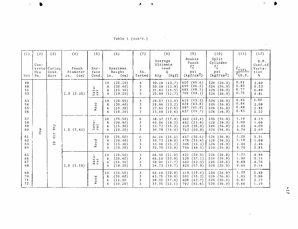
All test results are summarized in Tables 1 and 2. The
coefficient of variation in most cases is less that 5 per
cent (Table 1, Column 12).
The specimen generally failed with radial cracks
emitting from the center in approximately equal sections.
In some of the 10 inch and 8 inch specimens, fracture
occurred in two halves indicating a possible eccentric load
ing caused by slight misalignment of the two punches. In
the specimens 6 inches and smaller (including the cube
specimens) failure occ~rred in three or more sections of
radial failure. Examples of this multiple radial failure
can be seen in Fig. 3.
4.1 Effects of Dimensions
The effect of changing the surface area/loaded area
ratio was investigated by keeping the specimen diameter
constant at 6 inches while varying the punch diameter from
1.0 inch to 1.5 inches to 2.0 inches. By varying the
cylinder height, it was possible to determine the effect of

-7
height and loaded area vs. tensile strength.
In general, the 10 inch and 8 inch heights with the
1.0 inch punch, the calculated tensile strength was higher
than the split-cylinder tensile strength. When the 1.5
inch and 2.0 inch punches were used, the tensile strength
was less than the split-cylinder tensile strength. The
problems of eccentricity due to slight off-center of the
punches for the 10 inch and 8 inch specimens were signifi-
cant. The 6 inch high cylinders with the 1.0 inch, 1.5
inch, and 2.0 inch punches gave a tensile strength close
to that of the split-cylinder values. When the 1.0 inch
punch was used, however, the results were less consistent
than those for 1.5 inch and 2.0 inch punches. The 4 inch
cylinder with the 1.0 and 1.5 inch punches gave values
approximately equal to those of the split-cylinder test,
but when 2.0 inch punches were used, the value increased
greatly. A comparison of the tensile strengths can be ~b-
served in Table 1, Columns 9, 10, 11.
In Table 2, a comparison between the tensile strength
for the 6 inch high cylinders and those for the 6 inch
cubes is shown. It can be seen that the values of f'/f' c t
in Column 7 are almost identical, indicating that the shape
of the specimen has no effect on the test. The values f' c
used are those of the standard 6 inc~ by 12 inch compression
cylinder and of a 6 inch compression cube. The values of
ft are double punch tensile strengths.

-8
4.2 Effects of Concrete Mix, Curing Condition, and Age
For investigation of age effects, specimens composed
of the same mix proportions were cur~d for 7, 14, 21, and
28 days. Specimens of the same mix proportions were tested
at 28 days after moist curing for the full period, and also
after air-drying for half the period to determine the
effect of curing conditions. It was found that the 28 day
moist cured specimens gave the most consistent results in
the double-punch test. The 28 day air dry and lesser day
moist specimens gave good results, but with a little less
consistency than the 28 day moist. Results can be compared
in Table 1, Columns 9, 10, and 11, Sets 1 through 72, for
different ages and curing conditions.
Specimens of two different mix proportions were
tested at 28 days to investigate the effect of change in
composition. The relationship between the split-tensile
strength and the double-punch test for the different mixes
was approximately the same. This can be seen in Table 1,
Column 11, Sets 49 through 72 as compared with Sets 73
through 96 that the ratios of the split cylinder tensile
strength to that of the double punch tensile strength
correspond closely for both mixes.
4.3 Effects of Wooden Disk
Plywoo.d disks, 1/8 inch thick and with diameters
corresponding to those of the metal punches were used to
determine the effects of surface roughness between the
punch and the specimen. From Table 1, Columns 5 and 8, it

-9
can be seen that the wood disk caused a lower load at
failure but the difference is not significant. If the
surfaces of the specimen were troweled smooth during cast
ing, no wooden disks were necessary.
5. Double-Punch vs. Split Cylinder Testing Procedure
The double punch test has two major advantages over
the popular split-cylinder test, however, They involve
the relative simplicity of performance of the double punch
test over that of the split-cylinder test, and the fact
that a smaller machine can be used to perform the double
punch test.
In the split-cylinder test it is necessary to lay the
specimen lengthwise between the platens of the testing
machine, being careful to keep the specimen perfectly cen-
tered. Wooden strips must be placed on the top and bottom
contact surfaces of the cylinder, and then metal plates
are placed over the strips. The head of the machine must
then be lowered until contact is made with the specimen,
being careful that the specimen remains centered. Upon
failure, the specimen frequently 'explodes' in the machine,
after destroying the fracture pieces. In order to keep
the specimen intac~. a special device must be used.
In the double punch test one simply centers the
punches on the top and bottom surfaces with the templates,
being careful that there is no misalignment, tie a rope
around the perimeter of the cylinder to act as a shock
chord, lower the head of the machine, and load to failure.
The shock chord will hold the specimen together after
failure.
-10
The split cylinder test requires a load at failure
of approximately SO to 70 kips, while the proposed double
punch test requires only 30 to 40 kips. Since a smaller
machine is required for the double punch test, it may be
possible to perform the test in the field on small portable
testing machines, or in laboratories which do not have
larger machines.
The doulbe punch test also works satisfactorily
under the same procedure for a cube specimen. The proce
dure for performing a tensile test on a cube specimen is
much easier than performing a diagonal split-cube test.
For this reason, the double punch test would be good for
use in those countries which use cubes for testing.
5. Conclusions
Recommended Procedure for Performing Double Punch Test
The testing procedure proposed for most consistency
is one using a 6 inch high by 6 inch diameter cylinder with
two 1.5 inch diameter punches. No wood between the punches
and the surfaces of the specimens is recommended, providing
the surfaces are reasonable smooth. A smooth surface can
be obtained by careful trawling immediately after pouring.
For those countires which use cubes for testing, a 6
inch cube with 1.5 inch diameter punches and no wood is
recommended.
•
-,~.·
-11
6 • Acknowledgements
The research reported herein was supported by the
National Science Foundation under Grant GY-7459 to Lehigh
University for undergraduate research participation
(lambert Tall, project director); and as part of the re-
search to be conducted under Grant GK-14274 to Lehigh
University.
7. References
1. Timoshonko, S.
2.
Theory of Elasticity, McGraw-Hill Book Company, New York, pp. 104-108, 1934.
Chen, W. F. Extensibility of Concrete and Theorems of Limit Analysis, Journal of Engineering Mechanics Division, ASCE, Vol. 96, EM3, June, 1970, pp. 341-352.
3. Chen, W. F. Double Punch Test for Tensile Strength of Concrete, Journal of the American Concrete Institute, Vo 1. 6 7, December, 1970, pp. 993-995.

-12
•
Q
2a
H 2b
Q
DOUBLE PUNCH TEST
Fig. 1 Specimen Configurations for the New Test
-13
Fig. 2 Overall Picture of Setup

-14
Fig. 3 Failure Modes
I •

• ,
Table 1
Tensile Strength Computed from Double Punch Test and Split Cylinder Test
( 1 ) (2) (3) (4) (5) (6) (7) (8) (9) (10) ( 11) ( 12)
Average Double Split Punch Cylinder D.P.
Con- Ultimate f' f' Coef.of
I crete Curing Punch Sur- Specimen Load t t ftSPL. V:iria-
I Set ~!i X Cond. Diameter face Height No. Q psi psi f' tion No. days in. (em) Cond. in. (em) Tes.ted kip (kg£) (kgf/cm2) (kgf/cm2) tD.P, %
I 1 10 (25.50) 3 24.28 (11.0) 524 (36. 8). 507 (35. 6) 0.97 1. 54 2 I 8 (20.40) 3 24.78 (11.2) 534 (37.4) 507 (35.6) 0.95 2.72
;:l 3 .......... 6 (15.30) 3 20.55 (9.35)
I 443 (31.1) 507 (35.6) 1.14 1. 51
4 1.0 (2.55) "' "' 4 (10.20) 3 17.70 (8.02) 480 (33.7) .507 (35.6) 1. 06 0.28 Z 1-1 ; .....
<fl i
5 ·.-< 10 (25.50) 3 24.00 (10.9) 517 (36.3) 507 ( 35. 6) 0.98 2.36 6 0 8 (20.40) 3 23.05 (10.4) 497 (34.9) 507 (35.6) 1. 02 1.63 :::;: '"0
7 0 6 (15.30) 3 21.09 (9.56) 454 (31. 8) 507 (35.6) 1.12 0.28 " 0
8 :s: I 4 (10.20) 3 16.50 (7.47) 447 (31.4) 507 (35.6) 1.13 1. 51
9 10 (25.50) I 3 33.40 (15.2) 402 (28.2) 504 (35.4) 1. 25 2.50 I
10 ;:l 8 (20.40) 3 36.73 (16.6) 443 (31.1) 504 (35.4) 1. 14 0.89 11
.......... 6 (15.30) 3 28.65 (13.0) 434 (30.5) 504 (35.4) 1. 16 2.90 "' "' 12 ..... 1.5 (3.82) Z 1-1 4 (10.20) 3
<fl 23.30 (10.6) 536 (37 .6) 504 (35.4) 0.94 1. 43
<!) ·.-<
13 :::: 0 10 (25.50) 3 38.28 (17.4) 461 (32.4) 504 (35.4) 1. 09 0.19 0 :::;: 14 '"0 8 (20.40) 3 33.73 (15.3) 406 (28.4) 504 (35.4) 1. 24 3 .. 90
""" 0 15 ._, 0 6 (15.30) 3 28.73 (13.0) 435 (30.5) 504 (35.4) 1.16 2.33 16 :s: 4 (10.20) 3 23.50 (10.7) 541 (38.0) 504 ( 35. 4) 0.93 2.65
17 10 (25.50) 6 I 43.80 (19.9) 398 (27.9) 497 ( 34. 8) 1. 25 2.97 18
I 8 (20.40) 3 I 43.28 (19.7) 496 (34.8) 497 (34.8) 1. 00 8.27 ;:l I 19 ..... ..... ._, 6 (15.30) 3
I 35.38 (16.1) 547 (38.4) 497 (34. 8) 0.91 0.35
<fl "' "' 20 ·.-< 2. 0 (5.10) Z 1-1 4 (10.20) 3 31.45 (14.3) 749 (52.5) 497 (34.8) 0.66 2.60 0
:::;: I 21 ._, 10 (25.50) 3
I 47.85 (21.7) 436 (30.6) 497 (34. 8) 1. 14 0.21
22 N '"0 8 (20.40) 3 44.43 (20.2) 509 (35.8) 497 (34.8) 0.98 5.15 0
j 23 0 6 (15.30) 3 36.35 (16.5) 562 (39.4) 497 (34.8) i 0.89 2.66 24 :s: 4 (10.20) 3 i 31.35 (14.2) 745 (52.2) 497 (34.8) i 0.67 2.64
' ' I I

•
Table 1 (con 1t.)
( 1) (2) (3) (4) (5) (6) (7) (8)
Average Con- Ultimate crete Curing Punch Sur- Specimen Load ~!i X Cond. Diameter face Height No. Q
Set No. days in. (em) Cond. .in. (em) Tes.ted kip (kg f)
25 10 (25.50) 3 33.45 (15.2) 26 I 8 (20.40) 3 33.17 (15.1) ::l 27 ..,___, 6 (15.30) 3 26.70 (12.1) 28 1.0 (2.55) o:l o:l 4 (10.20) 3 21. 15 (9.60) Z H
29 10 (25.50) 3 30.60 (13.9) 30 ""' 8 (20.40) 3 29.55 (13.4) 0
31 0 6 (15.30) 3 25.50 (11.6) :== 32 4 (10.20) 3 20.96 (9.50)
33 10 (25.50) 6 42 . 48 (19.3) I
34 ::l 8 (20.40) 3 41.72 (18.9) 35 +J .-t 6 (15.30) 3 31.32 (14.2) o:l o:l
36 +J Vl
1.5 (3.82) Z H 4 (10.20) 3 26.4.4 (12.0) Cl) •rl
37 ~ 0 10 (25.50) 3 37.86 (17.1) 0 ::<: 38 ""' 8 (20.40) 3 38.88 (17.7)
00 0 39 N 0 6 (15.30) 3 31.35 (14.2) 40 :== 4 (10.20) 3 27.77 (12.6)
41 10 (25.50) 6 43.55 (19.8) 42 I
8 (20. 40) 3 44.30 (20.1) ;:I
43 +J .-t 6 (15.30) .3 38.15 (17.3) 2.0 (5.10) o:l o:l 44 Z H 4 (10.20) 3 33.68 (15.3)
45 10 (25.50) 3 45.35 (20.5) ""' 46 0 8 (20.40) 3 45.45 (20.6)
47 0 6 (15.30) 3 36.56 (16.6) :== 48 4 (10.20) 3 34.46 (15.6)
(9) (10)
Double Split Punch Cylinder
f1 t
f1 t
psi (kgf/cm2)
psi (kgf/cm2)
721 (50.6) 550 (38.6) 714 (50.1) 550 (38.6) 575 (40.3) 550 (38.6) 573 (40.2) 550 (38.6)
660 (46.3) 550 (38.6) 637 (44.7) 550 (38.6) 551 (38.6) 550 (38.6) 568 (39.8) 550 (38. 6)
512 (35. 9) 550 (38.6) 502 (35.2) 550 (38.6) 473 (33.2) 550 (38.6) 608 (42. 7) 550 (38.6)
456 (32.0) 550 (38.6) 467 (32.8) 550 (38.6) 475 (33.4) sso (38.6) 639 (44 ... 9.) 550 (38.6)
396 (27.8) 550 (38.6) 507 (35.6) 550 (38.6) 590 (41.4) 550 (38.6) 797 (55.9) 550 (.38.6)
412 (28.9) 550 (38.6) 521 (36.6) 550 (38.6) 565 (39.6) 550 (38.6) 819 (57.5) 550 (38.6)
( 11)
f~SPL. f1
tD.P.
].76 ].77 0.96 0.96
0.84 0.86 1. 00 0.97
1. 07 1.10 1.16 0.91
1. 20 1.18 1.16 0.86
1. 39 1. 08 3.93 0.69
1. 33 1. OS 0.98 0.67
( 1 2)
D.P. Coef.of V3.ria-tion
%
1. 20 3.75 1. 17 2.05
3.50 2.34 1. 83 3.63
4.00 1. 7 3 1. 83 3.00
5.00 4.14 3.16 3.52
4.50 0.91 0.00 2.87
5.74 7.16 0.88 3.11
I 1-' 0'\
' •
Table 1 (con't.)
( 1 ) ( 2) (3) (4) (5) (6) (7) (8) (9) (10) ( 11) ( 1 2)
Average Double Split
D.P. Punch Cylinder Con- Ultimate f' f' Coef.of crete Curing Punch Sur- Specimen Load t t f~SPL. v~ria-Hix Cond. Diameter face Height No. Q psi psi f' tion
Set No. days in. (em) Cond. in. (em) Tested kip (kg f) (kgf/cm2) (kgf/cm2) tD.P, %
49 10 (25.50) 6 30.18 (13.7) 650 (45.6) 526 (36.9) 0.81 3.60 so I 8 (20.40) 3 30.58 (13.9) 659 (46.2) 526 (36. 9) 0.80 0. 3 2 51
;:l 6 (15.30) 3 31.82 (14.5) 685 (48.1) 526 (36.9) 0.77 0.89 ...........
52 1.0 (2.55) C1S C1S 4 (10.20) 3 25.84 (11.7) 700 (49.1) 526 (36.9) 0.75 4.81 z ...
53 I 10 (25.50) 3 28.57 (13.0) 615 (43.2) 526 (36.9) 0.85 3.00 54 "C) 8 (20.40) 3 28.96 (13.2) 624 (43.8) 526 (36.9) 0.84 2.09 0 55 I 0 6 (15.30) 3 27.65 (12.5) 597 (41.9) 526 (36.9) 0.88 1.93 56
:s: 4 (10.20) 3 23.48 (10.6) 637 (44.7) 526 ( 3 6. 9) 0.83 1. 32
57 10 (25.50) 6 38.37 (17.4) 462 (32.4) 526 (36.9) 1.14 4.13 I
58 ;:l 8 (20.40) 3 40.06 (18.2) 482 (33.8) 526 (36.9) 1. 09 1. 06 59 >. ........... 6 (15.30) 3 33.72 (15.3) 510 (35.8) 526 (36.9) 1.03 4.00 ... C1S C1S
60
I Q) Cl 1.5 (3.82) Z f.< 4 (10.20) '3 30.78 (14.0) 713 (50.0) 526 (36. 9) 0.74 2.63 ~
0 ... 61 ·..-< 10 (25.50) 6 36.28 (16.5) 437 (30.6) 526 (36.9) 1. 20 3. 31
' ~ 62
I "C) 8 (20.40) 3 39.72 (18.0) 478 (33. 6) 526 (36.9) 1. 10 1. 68
C() 0 63 N 0 6 (15.30) 3 33.46 (15.2) 506 (35.5) 526 (36.9) 1. 04 2.46 64 ! :s: 4 (10.20) 3 30.70 (13.9) 706 (49.5) 526 (36.9) 0.75 2.83
I (29.5) (36.9) 1 . 2 5 65 I I 10 (25.50) 3 46.30 (21.0) 421 526 4.49
66 ;:l 8 (20.40) 3 46.10 (20.9) 528 ( 3 7 . 1.) 526 (36.9) 1. 00 3.14 ........... 67 C1S C1S 6 (15.30) 3 38.94 (17.7) 602 (42. 3) 526 (36.9) 0.88 4.76 z ... 68 2.0 (5. 10) 4 (10.20) 3 34.73 (15.7) 825 (57.9) 526 (36.9) 0.64 0.14
69 10 (25.50) 3 46.18 (20.9) 419 (29.4) 526 (36.9) 1 . 2 5 5.49 70 "C) 8 (20.40) 3 43.75 (19.8) 501 (35.2) 526 (36. 9) 1 . 0 5 2.98 71 0 6 (15.30 3 39.33 (17.8) 608 (42.7) 526 (36.9) 0.87 2. 17 0 72 :s: 4 (10.20) 3 33.35 (15.1) 792 (55.6) 526 (36. 9) 0.66 1. 19
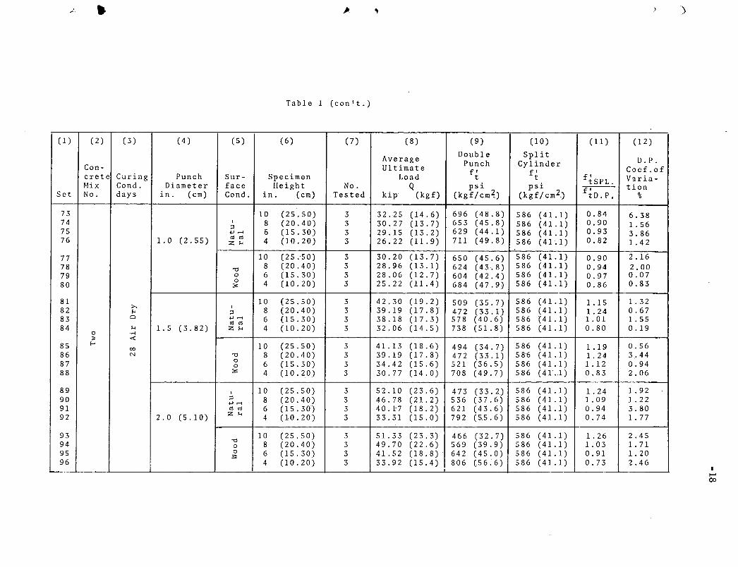
Table 1 (con't.)
( 1) (2) (3) (4) (5) (6) (7)
Con-crete Curing Punch Sur- Specimen Mix Cond. Diameter face Height No.
Set No. days in. (em) Cond. in. (em) Tes.ted
73 10 (25.50) 3 74 I 8 (20. 40) 3 ;::l 75 ..... ,...., 0 (15.30) 3 76 1.0 (2.55) ro ro 4 (10.20) 3 z !-<
77 10 (25. 50) 3 78 "0 8 (20.40) 3 79 0 6 (15.30) 3 80
0 4 (10.20) 3 :;:
81 10 (25. 50) 3 >. I 82 !-< ;::l 8 (20. 40) 3
83 0 ..... ,...., 6 (15.30) 3 ro ro 84 !-< 1.5 (3.82) z !-< 4 (10.20) 3
0 .,; ;;: <(
85 E-o 10 (25.50) 3 00
86 N "0 8 (20.40) 3 87 0 6 (15.30) 3 0
88 :;: 4 (10.20) 3
89 I 10 (25.50) 3 90 ;::l 8 (20.40) 3 ..... ,...., 91 ro ro 6 (15.30) 3 92 2.0 (5.10) z !-< 4 (10.20) 3
93 10 (25.50) 3 94 "0
8 (20.40) 3 0
95 0 6 (15.30) 3 :;: 96 4 (10.20) 3
(8) (9)
Average Double Punch Ultimate f' Load t
Q psi kip (kg£) (kgf/cm2)
32.25 (14.6) 696 (48.8) 30.27 (13.7) 653 (45.8) 29.15 (13.2) 629 (44.1) 26.22 (11.9) 711 (49.8)
30.20 (13.7) 650 (45.6) 28.96 (13.1) 624 (43.8) 28.06 (12.7) 604 (42.4) 25.22 (11.4) 684 (47.9)
42.30 (19.2) 509 (35.7) 39.19 (17.8} 472 (33.1) 38.18 (17.3) 578 (40. 6) 32.06 (14.5) 738 (5i.8)
41.13 (18.6) 494 ( 34. 7) 39.19 (17.8) 472 (33.1) 34.42 (15.6) 521 (36.5) 30.77 (14.0) 708 (49.7)
52.10 (23.6) 473 ( 3 3. 2) 46.78 (21.2) 536 (37.6) 40.1-7 (18.2) 621 (43.6) 33.31 (15.0) 792 (55.6)
51.33 (23.3) 466 (32.7) 49.70 (22.6) 569 (39.9) 41.52 (18.8) 642 (45.0) 33.92 (15.4) 806 (.56. 6)
(10)
Split Cylinder
f' t psi
(kgf/cm2.)
586 (41.1) 586 (41.1) 586 (41.1) 586 (41.1)
586 (41.1) 586 (41.1) 586 (41.1) 586 (41.1)
586 (41.1) 586 (41.1) 586 (41.1) 586 (41.1)
586 (41.1) 586 (41.1) 5 86 (41.1) .586 ( 41 .. 1)
586 (41.1) 586 (41.1) 586 (41.1) 586 (4.1.1)
586 (41.1) 586 (41.1) 586 (41.1) 586 (41.1)
( 11)
ftSPL. f' tD.P,
0.84 0.90 0.93 0.82
0.90 0.94 0.97 0.86
1.15 1. 24 1. 01 0.80
1.19 1. 24 1.12 0.83
1. 24 1. 09 0.94 0.74
1. 26 1. 03 0.91 0.73
)
(12)
D.p. Coef.of V::tria-tion
%
6.38 1. 56 3.86 i. 42
2.16 2.00 0.07 0.83
1. 32 0.67 1. 55 0.19
0.56 3 .. 44 0.94 2.06
1. 92 1. 22 3.80 1. 77
2.45 1. 71 1. 20 2.46
)
I t-' 00

• •
Table 2
Double Punch Test for 6 Inch High Cylinders and Cubes
( 1) (2) (3) ( 4) * (5) (6) (7)
Average Double Simple
Ultimate Punch Compression f' f' Curing Punch Load t c f'
Cond. Diameter Q psi c ps1 f~D.P. Specimen Days in. (em) kip (kg). (kgf/cm 2 ) (kgf/cm2)
1-< ~
(!) r-. Ul 1. 0 (2.55) 26.70 (12.1) 575 (40.3) 6510 (457) 11.3 '"0 s 00 .,..;
l 1 . 5 (3.82) 31.32 (14.2) 473 (33.2) 6510 (457) 13.7 s:: u 1-< N 0 .,..; (!)
..,.. 2.0 (5.10) 38.15 (17.3) 590 (41.4) 6510 ( 4 57) 11 . 0 "'""' .-iO"'CC
>-. I") s:: I 1.0 (2.55) 31.82 (14.5) 685 (48.1) 6960 ( 4 8 8) 10. 2 u .. ,..;
lfl .-i 00!-<>-. 1 . 5 (3.82) 33.72 (15.3) 510 (35.8) 6960 ( 4 8 8) 13.6 = .-i >-. N·..; 1-< \ \C) '-' u <Cl 2.0 (5.10) 38.94 (17.6) 602 (42.2) 6960 ( 4 88) 11.5
~ 1.0 (2.55) 28.96 (13.1) 624 (43.8) 7188** (505) 11.5 r-. Ul
s 00 .,..; 1.5 (3.8w4.18 (15 .5) 549 (38.6) 7188 (505) 13. 1 u N 0
(!) ::E 2 . ~-__1?_:]_9 ) 3 9 . 6 2 (18.0) 613 (43.0) 7188 (505) 1 1 . 7 ..co f-·--· ·- - ~--·---·-···
;::ltrl 1.0 (2.55) 1 28.70 (13.0) 619 (43.4) 7188 (505) 11.6 u o(l)
lfl..C OO!-<>-. 1 . 5 (3.82) \ 33.46 (15.2) 507 (35:6) 7188 (5OS) 14. 1 = .-i ;:I N•..; 1-< \C) '--' u <Cl I 2.0 (5.10) I 40.74 (18.5) 6 31 (44.3) 7188 (50 5) 11. 4
* Average of three tests with natural surface
** Compression cube