door installation instructions
TRANSCRIPT
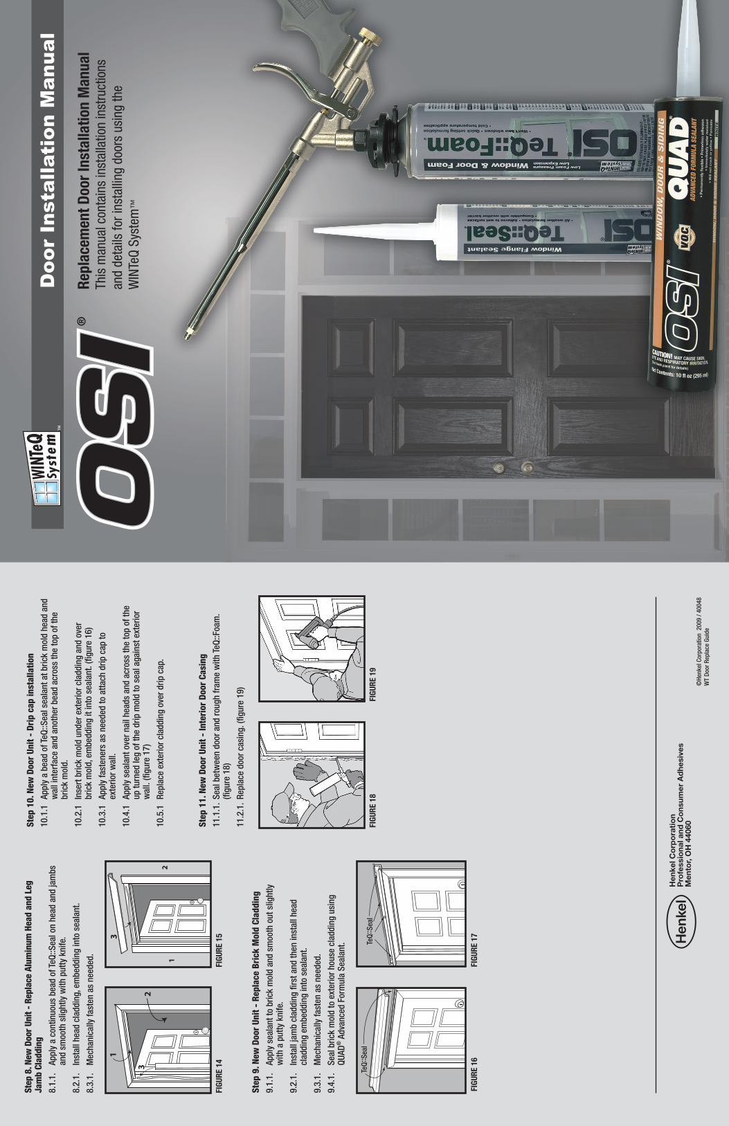
Repl
acem
ent D
oor I
nsta
llatio
n M
anua
lTh
is m
anua
l con
tain
s in
stal
latio
n in
stru
ctio
ns
and
deta
ils fo
r ins
talli
ng d
oors
usi
ng th
e W
INTe
Q Sy
stem
™
©H
en
kel C
orp
ora
tion
2009 /
40048
WT D
oor
Rep
lace
Gu
ide
Hen
kel C
orp
ora
tio
nP
rofe
ssio
nal a
nd C
ons
umer
Ad
hesi
ves
Men
tor,
OH
440
60
Doo
r In
stal
lati
on M
anua
l
FIGU
RE 1
8FI
GURE
19
Step
8. N
ew D
oor
Unit
- Re
plac
e Al
umin
um H
ead
and
Leg
Jam
b Cl
addi
ng8.1
.1.
Ap
ply
a c
on
tin
uou
s b
ead
of
TeQ
::S
eal on
head
an
d jam
bs
an
d s
mooth
slig
htl
y w
ith
pu
tty
kn
ife.
8.2
.1.
Inst
all
head
cla
dd
ing, e
mb
ed
din
g in
to s
eala
nt.
8.3
.1.
Mech
an
ically
fast
en
as
need
ed
.
Step
9. N
ew D
oor
Unit
- Re
plac
e Br
ick
Mol
d Cl
addi
ng9.1
.1.
A
pp
ly s
eala
nt
to b
rick
mold
an
d s
mooth
ou
t sl
igh
tly
wit
h a
pu
tty
kn
ife.
9.2
.1.
In
stall
jam
b c
lad
din
g fi
rst
an
d t
hen
in
stall
head
cl
ad
din
g e
mb
ed
din
g in
to s
eala
nt.
9.3
.1.
M
ech
an
ically
fast
en
as
need
ed
.
9.4
.1.
S
eal b
rick
mold
to e
xteri
or
hou
se c
lad
din
g u
sin
g
Q
UA
D® A
dva
nce
d F
orm
ula
Seala
nt.
Step
10.
New
Doo
r Un
it -
Drip
cap
inst
alla
tion
10.1
.1
Ap
ply
a b
ead
of
TeQ
::S
eal se
ala
nt
at
bri
ck m
old
head
an
d
w
all
inte
rface
an
d a
noth
er
bead
acr
oss
th
e t
op
of
the
b
rick
mold
.
10.2
.1
Inse
rt b
rick
mold
un
der
exte
rior
clad
din
g a
nd
ove
r
b
rick
mold
, em
bed
din
g it
into
seala
nt.
(fi
gu
re 1
6)
10.3
.1
Ap
ply
fast
en
ers
as
need
ed
to a
ttach
dri
p c
ap
to
ex
teri
or
wall.
10.4
.1
Ap
ply
seala
nt
over
nail
head
s an
d a
cross
th
e t
op
of
the
u
p t
urn
ed
leg
of
the d
rip
mold
to s
eal ag
ain
st e
xteri
or
wall.
(fi
gu
re 1
7)
10.5
.1
Rep
lace
ext
eri
or
clad
din
g o
ver
dri
p c
ap.
Step
11.
New
Doo
r Un
it -
Inte
rior
Doo
r Ca
sing
11.1
.1. S
eal b
etw
een
door
an
d r
ou
gh
fra
me w
ith
TeQ
::Foam
.
(fi
gu
re 1
8)
11.2
.1. R
ep
lace
door
casi
ng. (fi
gu
re 1
9)
1
23
12
3
FIGU
RE 1
4FI
GURE
15
TeQ
::S
eal
FIGU
RE 1
6FI
GURE
17
TeQ
::S
eal
Dete
rmin
e re
plac
emen
t doo
r un
it si
ze:
Mea
sure
insi
de ja
mb
to in
side
jam
b an
d ad
d ja
mb
wid
th x
2 =
ove
rall
door
uni
t wid
th. M
easu
re th
e th
resh
old
base
to th
e to
p of
the
insi
de
head
er fr
ame
and
add
head
wid
th =
ove
rall d
oor u
nit h
eigh
t. (D
eter
min
e hi
gh s
ide
of ja
mb
inte
rior o
r ext
erio
r to
insu
re th
at th
e ne
w d
oor w
ill
fit in
the
open
ing.
Step
1. P
re In
spec
tion:
Bef
ore
rem
ovin
g ex
istin
g do
or, c
heck
:1.1
.1.
Ch
eck
an
d c
on
firm
new
door
measu
rem
en
ts.
1.2
.1.
Ch
eck
hard
ware
.
1.3
.1.
Ch
eck
colo
r an
d fi
nis
h.
1.4
.1.
Ch
eck
door
swin
g.
Step
2. E
xist
ing
Door
2.1
.1.
Care
fully
rem
ove t
he o
ld d
oor.
2.2
.1.
Ch
eck
rou
gh
op
en
ing
for
plu
mb
an
d leve
l.
2.3
.1.
Ad
just
th
resh
old
base
if
it is
not
leve
l (i
t m
ay
be n
ece
ssary
to u
se leve
ling
com
pou
nd
or
sim
ilar
mate
rial to
leve
l
th
resh
old
base
).
TI
P: T
ake
not
e of
dis
tan
ce o
f b
ase
mol
din
g f
rom
doo
r, tr
y to
ce
nter
the
door
to a
llow
for
door
cas
ing
to li
mit
cut
ting
and
fitt
ing
late
r on
. M
ark
floo
r w
ith
tap
e to
hel
p w
ith
rea
lign
men
t la
ter
on.
(fig
ure
2)
Step
3. N
ew D
oor
Unit
3.1
.1.
If
sup
plie
d, r
em
ove a
lum
inu
m c
lad
din
g f
rom
bri
ck m
old
.
(fi
gu
re 3
)
3.2
.1.
Rem
ove jam
b c
lad
din
g. (fi
gu
re 4
)
3.3
.1.
Dry
fit
door
fram
e in
to o
pen
ing.
3.4
.1.
Ch
eck
for
plu
mb
an
d leve
l.
FIGU
RE 2
1
23
1
2
3
rem
ove b
rick
mold
cla
dd
ing
(if
sup
plie
d)
rem
ove jam
b &
head
cla
dd
ing
(if
sup
plie
d)
FIGU
RE 3
FIGU
RE 4
ABD E
FC
FIGU
RE 1
1
FIGU
RE 5
3.5
.1.
Rem
ove f
ram
e f
rom
op
en
ing.
3.6
.1.
Op
tion
al b
est
pra
ctic
e r
eco
mm
en
dati
on
3.6
.2.
Inst
all
rid
gid
sill
pan
or
site
bu
ilt s
ill p
an
per
AS
TM
E2112
inst
alla
tion
pra
ctic
es.
(fi
gu
re 6
- 7
)
3.7
.1. A
pp
ly T
eQ
::S
eal W
ind
ow F
lan
ge B
ed
din
g S
eala
nt
to s
ill.
(fi
gu
re 5
)
3.8
.1. A
pp
ly T
eQ
::S
eal to
bri
ck m
old
. (fi
gu
re 8
)
3.9
.1. R
ep
lace
door
into
op
en
ing.
3.1
0.1
. R
ead
just
an
d a
lign
door
into
op
en
ing.
Step
4. N
ew D
oor
Unit
- Sh
im P
lace
men
t4.1
.1. A
. P
lace
sh
im a
t lo
wer
hin
ge s
ide.
B
. P
lace
sh
im a
t lo
wer
stri
ke s
ide.
C
. P
lace
sh
im a
t u
pp
er
hin
ge s
ide.
D
. P
lace
sh
im a
t u
pp
er
stri
ke s
ide.
E
. P
lace
sh
im a
t ce
nte
r st
rike
sid
e.
F.
Pla
ce s
him
at
cen
ter
hin
ge s
ide (fi
gu
re 9
)
ABD E
FC FIGU
RE 9
Step
5. N
ew D
oor
Unit
- Hi
nge
Side
Fas
teni
ng5.1
.1.
Mec
han
ical
ly f
aste
n ja
mb
to
rou
gh
op
enin
g f
ram
e n
ear
shim
s at
top
an
d b
otto
m o
f d
oor
fram
e (d
o n
ot a
ttac
h
th
rou
gh
sh
ims
at t
his
tim
e).
5.2
.1.
Mou
nt
new
doo
r sl
ab t
o d
oor
fram
e.
5.3
.1.
Sh
im b
ehin
d h
ing
es b
ein
g c
aref
ul n
ot t
o ov
er s
him
an
d
b
ow d
oor
fram
e.
5.4
.1.
Pre
dri
ll p
ilot
hol
es in
hin
ges
an
d s
trik
e p
late
to
allo
w f
or
an
chor
scr
ews.
5.5
.1.
Pla
ce 1
scr
ew in
up
per
hin
ge
(do
not
dri
ve a
ll th
e w
ay in
at
this
tim
e) C
hec
k g
ap a
rou
nd
doo
r an
d d
oor
fram
e to
en
sure
that
an
eve
n 1
/8”
or le
ss g
ap is
mai
nta
ined
. S
him
to
adju
st
fo
r u
nif
orm
gap
.
FIGU
RE 1
2
colo
r &
tex
ture
insi
de jam
b t
o in
sid
e
jam
b +
jam
b w
idth
x2
(left
han
d in
swin
g)
inte
rior
exte
rior
inte
rior
exte
rior
rig
ht
hin
ge in
swin
g
left
hin
ge in
swin
g
(rig
ht
han
d in
swin
g)
thre
shol
d
to h
ead +
hea
d w
idth
FIGU
RE 1
FIGU
RE 1
3 -
un
even
FIGU
RE 1
4 -
ev
en
FIGU
RE 1
3
5.6
.1.
Pla
ce s
crew
at
low
er h
ing
e, c
hec
k g
ap a
nd
ad
just
.
5.7
.1.
Sh
im m
idd
le h
ing
e an
d s
et s
crew
, ch
eck
and
mai
nta
in g
ap.
5.8
.1.
Fin
ish
inst
allin
g a
nd
set
tin
g a
ll sc
rew
s on
th
e h
ing
es.
5.9
.1.
Sco
re a
nd
sn
ap o
ff p
rotr
ud
ing
sh
ims
flu
sh t
o in
teri
or
w
all s
urf
ace.
Step
6. N
ew D
oor
Unit
- St
rike
Sid
e Fa
sten
ing
6.1
.1.
Pla
ce s
him
un
der
str
ike
to a
dju
st a
nd
hol
d g
ap a
s n
eed
ed,
app
ly f
aste
ner
at
top
an
d b
otto
m o
f d
oor
fram
e ja
mb
th
en
fast
en in
mid
dle
nea
r st
rike
, ad
just
sh
ims
as n
eed
ed.
6.2
.1.
Cu
t b
ack
shim
s fl
ush
to
open
ing
Inst
all l
ock
har
dw
are
follo
win
g t
he
pro
vid
ed in
stru
ctio
ns.
Step
7. N
ew D
oor
Unit
Alig
nmen
t Che
ck -
Ad
just
ab
le T
hre
shold
7.1
.1.
Adj
usta
ble
Thre
shol
d
Ad
just
ab
le c
om
posi
te t
hre
shold
allo
ws
a s
imp
le h
eig
ht
ad
just
men
t fo
r p
erf
ect
door
alig
nm
en
t to
seal ou
t b
ott
om
d
raft
s. A
dju
st t
hre
shold
so t
hat
door
sweep
con
tact
is
eve
n
acr
oss
th
resh
old
. (fi
gu
re 1
2)
Inst
all C
orne
r Pa
dsSp
ecia
lly d
esig
ned
corn
er p
ads
use
a cu
t out
to c
reat
e a
low
pre
ssur
e ca
vity
that
pre
vent
s “s
traw
wic
king
” ef
fect
and
elim
inat
es a
ssoc
iate
d le
aks
unde
r st
orm
y co
nditi
ons.
FIGU
RE 6
FIGU
RE 7
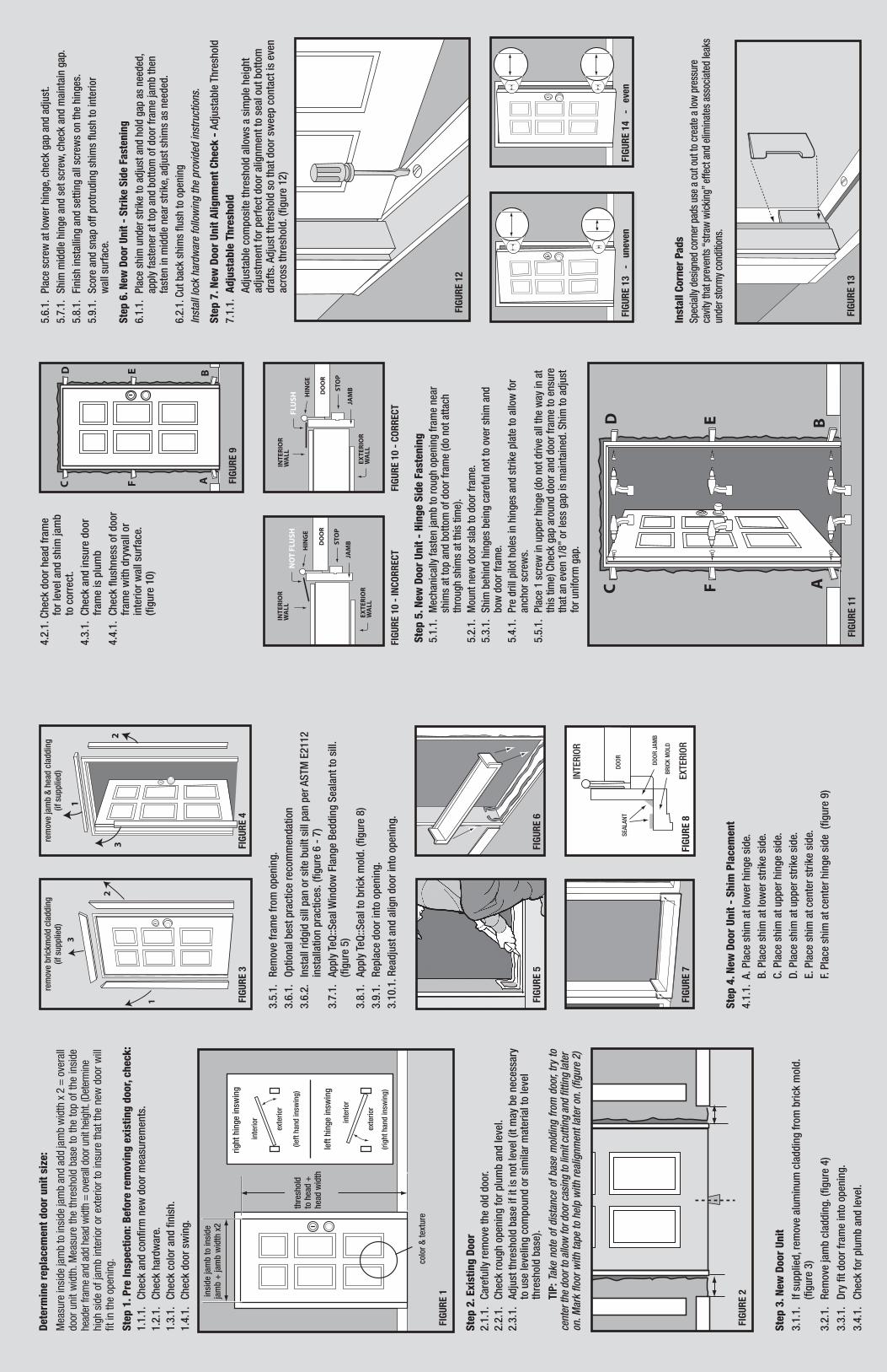
4.2
.1.
Ch
eck
door
head
fra
me
fo
r le
vel an
d s
him
jam
b
to
corr
ect
.
4.3
.1.
Ch
eck
an
d in
sure
door
fr
am
e is
plu
mb
4.4
.1.
Ch
eck
flu
shn
ess
of
door
fr
am
e w
ith
dry
wall
or
in
teri
or
wall
surf
ace
.
(fig
ure
10)
JAM
BSTO
P
HIN
GE
INTE
RIO
RW
ALL
EXTE
RIO
RW
ALL
DO
OR
FLU
SH
JAM
BSTO
P
HIN
GE
INTE
RIO
RW
ALL
EXTE
RIO
RW
ALL
DO
OR
NO
T FL
USH
FIGU
RE 1
0 -
INCO
RREC
TFI
GURE
10
- CO
RREC
T
FIGU
RE 8
DO
OR
JA
MB
DO
OR
BR
ICK
MO
LD
SE
ALA
NT
EX
TE
RIO
R
INTE
RIO
R