doi: 10.1361/154770205x76303 1547-7029 / $19.00 … 10.1361/154770205x76303 1547-7029 / $19.00...
TRANSCRIPT
54 Journal of Failure Analysis and PreventionVolume 5(6) December 2005
Evaluation of a Leaf Spring Failure (continued)
(Submitted July 18, 2005; in revised form August 31, 2005)
The determination of the point of failure during an accident sequence of a rear leaf spring in a sportutility vehicle is presented in terms of fracture surface analysis and residual-strength estimates. Marks atthe scene of the accident pointed to two possibilities for the point of failure: marks in the roadway at thestart of the accident sequence and a rock strike near the end of the sequence. Evidence from rust andchemical contamination on the fracture pointed to the spring having been cracked in half prior to theaccident. Extensive woody fracture and secondary cracking at the midplane of the spring was evidence forsegregation and weakness in the spring. Stress estimates for the effect of both the weakness and priorcracking on the residual strength of the spring revealed reductions in strength of the spring that couldproduce fracture at the start of the accident sequence. The point of failure of the spring was placed at thestart of the accident sequence.
Keywords:
JFAPBC (2005) 6:54-63 © ASM InternationalDOI: 10.1361/154770205X76303 1547-7029 / $19.00
IntroductionIdentification of the point in time that a fracture
occurs can be crucial in the reconstruction of anaccident, particularly those involving vehicles.Evidence to identify the point in time of the failurecan be found in different forms. The failure analysispresented in this paper made use of evidence forfracture surface contamination, unusual fracturemorphology, stress analysis, and fracture mechanicsto identify the point in time in an accident sequenceof an automotive leaf spring failure. This work grewout of a larger investigation of a loss-of-controlaccident in which both a rear leaf spring and a rearaxle were found broken after the accident. Theobvious question was, “Did one of these componentscause the accident, or were they the result of theaccident?” A brief description of the accident follows.
Written reports, statements, and a measured mapof the scene showing road mark and object locationsreveal that the vehicle was traveling at approximately60 to 70 km/h on a dirt road when a clicking noisewas heard upon entering a gentle curve that randownhill. The vehicle drifted to the left side of theroad, then turned sharply to the right across the roadand sharply back to the left. The vehicle then ranalong the left edge of the road until it struck largerocks. Impact with the rocks was along the left sideof the vehicle. The vehicle rolled at this point,according to some reports. The right rear wheel was
C.K. Clarke, Metallurgical Consulting, 1146 Leroy Stevens Rd., Suite A, Mobile, AL 36695. G.E. Borowski, Borowski Engineering,1420 Polaris Dr., Mobile, AL 36693. Contact e-mail: [email protected] and [email protected].
fracture mechanics, leaf spring failure, leaf spring stress analysis, woody fracture
Evaluation of a Leaf Spring FailureC.K. Clarke and G.E. Borowski
found fully inflated in the middle of the road nearthe start of the accident sequence. Subsequentinspection revealed that the left rear spring wasbroken at the forward eye and was bent sharplyupward at the rear end of the first helper leaf.
The following day, investigators at the accidentscene found marks in the dirt road that were wellpreserved and were the basis for mapping the pathof the vehicle. They also found marks consistent withthe right rear brake backing plate contacting the dirtroadway early in the sequence. A geological analysisof dirt found embedded in the backing plate deter-mined that it was consistent with the roadbed mater-ials, which were primarily limestone and sand. Soiloutside the roadbed was different and was primarilyred sand with little limestone. Quantitative analysisof the material in the backing plate was close to thatof the roadbed materials and distinctly differentfrom the surrounding terrain. No marks from a singlerolling or bouncing tire in the road were reportedfurther down the roadway.
Examination of the vehicle revealed the presenceof rotating tire rub marks in the aft end of the leftrear wheelwell and rotating tire rub marks in theforward end of the right rear wheelwell. Rupture ofthe left rear spring at the forward attachment wouldallow the left side of the axle to pivot to the rearabout the right side spring-to-axle connection. Thus,the left wheel would rub at the rear of the wheelwell,

55Journal of Failure Analysis and Prevention Volume 5(6) December 2005
and the right wheel would rub forward into thewheelwell. The pivoting axle will produce a steeringeffect independent of the front wheels and lever theright rear wheel into the frame rail. Because the tirerub marks show that the right rear wheel was as yetstill rotating and unbroken, the left rear spring brokefirst. Therefore, the rest of the investigation wasfocused on the failure of the left rear spring.
Spring Fracture EvaluationFracture of the spring occurred at the formed
forward eye, as shown in Fig. 1. Comparison of theeye with unbroken springs revealed that it hadsomewhat unwrapped prior to the failure. Theposition of the two broken ends in Fig. 1 exaggeratesthe prior deformation. Striking features of thefracture were the presence of extensive secondarycracking at the midplane, the stepped nature of thefracture, and “woody fracture” on the stepped surfaceparallel to the spring surface. Figure 2 shows theoverall fracture with the secondary cracking. The
woody fracture was difficult to photograph becauseit faced the spring surface. Damage to the oppositehalf of the fracture prevented much work with it.Permission to cut the eye half of the fracture forbetter examination was never granted.
Figure 2 shows a distinct division of the fracturealong the midplane. Stereomicroscopy revealed a stepin the fracture surface at this location, with deepsecondary cracking along 73% of the midplane. Anold, rusty crack was also observed along the outsidesurface over most of the width of the spring. Thisold crack (arrows) is shown in a higher-magnificationview in Fig. 3. The outer half of the fracture withthe old crack was also observed to have rust,compared to the inner half. Figure 4 shows the insidefracture surface opposite that in Fig. 3. The outsidesurface clearly shows areas of rust, particularly alongthe old crack. The inner half of the spring fracture
Fig. 2 The spring half of the fracture has deep secondary crackingalong the midplane.
Fig. 4 This area of the inner half of the fracture across from thearea in Fig. 3 is clear of rust.
Fig. 1 The broken halves of the spring have been placed togetherin a manner exaggerating the opening of the eye beforerupture.
Fig. 3 The outer half of the fracture surface was observed to haverust in places. The old crack (arrows) along most of theouter surface is clearly rusted.

56 Journal of Failure Analysis and PreventionVolume 5(6) December 2005
Evaluation of a Leaf Spring Failure (continued)
was devoid of rust. Figures 3 and 4 were taken underidentical conditions using Ektachrome 4 × 5 sheetfilm (Eastman Kodak Co.) in order to faithfullyrecord the color differences and serve as the basisfor color printing.
A scanning electron microscope (SEM) was usedto examine the fracture on the eye at higher magni-fications. Examination of the midplane fracture wasdifficult because the midplane fracture surface facedthe surface of the spring itself. Such a geometrycreates signal detection problems, particularly forX-ray analysis.[1] However, significant results wereachieved by repeated repositioning of the spring eye.
The SEM fractograph of the spring eye fracturein Fig. 5 clearly shows the midplane cracking and
old crack along the outside diameter (OD) surface(arrows). This old crack exhibited features indicativeof a corroded surface, as can be seen in Fig. 6. Frac-ture between the old crack and the midplane wasalso rusted but less so than the old crack. The fracturemode in the old crack was difficult to see because ofcorrosion and physical damage. However, a few smallareas were clear enough to reveal uniform, very smallmicrovoids. Fracture between the old crack and themidplane was also by microvoid coalescence, but thevoid size was duplex with large and small microvoids.The fracture was also rougher.
X-ray spectroscopy of the old crack in the SEMrevealed unusually high peaks for oxygen, silicon,calcium, chlorine, sulfur, and aluminum. Figure 7shows one of the X-ray spectra from the old crack.
Calcium, silicon, and aluminum are contaminationelements, because they should not be present at theobserved concentrations on a 5160 steel fracturesurface. The geological report revealed calcium car-bonate, alumina, and, to a lesser extent, silica were amajor portion of the road material. Chlorine wasnot reported in the roadbed analysis, and roads arenot salted for ice where the vehicle was driven. An
Fig. 6 More detail of the old crack (arrows) shows a rustedsurface compared with fracture next to it.
Fig. 5 This area of the spring eye half of the fracture clearlyshows secondary cracks at the midplane and an old crack(arrows) at the outside surface.
Fig. 7 X-ray spectra from the old crack yielded high levels ofcarbon and oxygen. The other elements—calcium, alumi-num, and silicon—are consistent with the road material.Chlorine can only be explained by ocean shipment.
57Journal of Failure Analysis and Prevention Volume 5(6) December 2005
obvious source for chlorine in this case was the knowntransport of the vehicle by an ocean-going ship. Thehigh oxygen level is consistent with corrosion. Thesource of the sulfur is not known at this time.
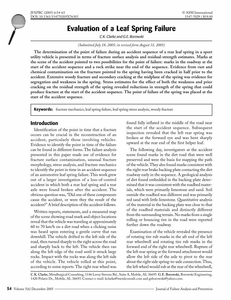
Figure 8 shows one area of “thumbnail-shaped”crack origins on the inside diameter (ID) surface.Chevron marks can be seen emanating from smallerthumbnails in Fig. 4. These regions were at an angleto the fracture and probably constitute a slow tearor low-cycle-fatigue-type feature. They triggered thefinal rupture of the spring.
Figure 9 shows a representative area of fractureapproximately halfway between the inside surfaceof the spring eye and the midplane fracture. Thisfracture surface is perpendicular to the long axis of
the spring. Extensive intergranular fracture mixedwith microvoids was observed in this region of thefracture. Grain boundaries in steel are stronger thanthe grains at normal operating temperatures,[2] unlessan element or compound develops on the boundariesand weakens them.[3-5] Steels with this problemoften exhibit lower toughness and are more sensitiveto shock or rapid loading. There are a number ofphenomena that can produce this problem. Leafsprings are normally hot formed, quenched, andtempered. Prolonged cooling through or temperingat certain temperature ranges can produce temperembrittlement that can result in the observedintergranular fracture. Under the proper conditions,sulfides can also penetrate grain boundaries as thinfilms and produce intergranular fracture at elevatedtemperatures.
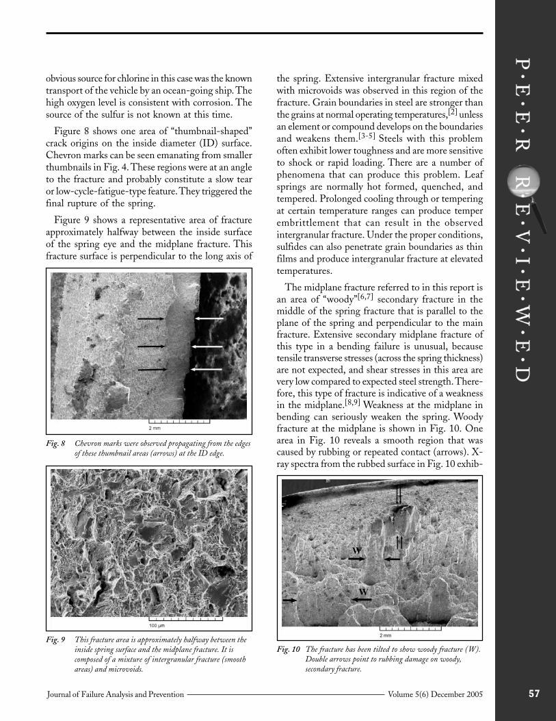
The midplane fracture referred to in this report isan area of “woody”[6,7] secondary fracture in themiddle of the spring fracture that is parallel to theplane of the spring and perpendicular to the mainfracture. Extensive secondary midplane fracture ofthis type in a bending failure is unusual, becausetensile transverse stresses (across the spring thickness)are not expected, and shear stresses in this area arevery low compared to expected steel strength. There-fore, this type of fracture is indicative of a weaknessin the midplane.[8,9] Weakness at the midplane inbending can seriously weaken the spring. Woodyfracture at the midplane is shown in Fig. 10. Onearea in Fig. 10 reveals a smooth region that wascaused by rubbing or repeated contact (arrows). X-ray spectra from the rubbed surface in Fig. 10 exhib-
Fig. 8 Chevron marks were observed propagating from the edgesof these thumbnail areas (arrows) at the ID edge.
Fig. 9 This fracture area is approximately halfway between theinside spring surface and the midplane fracture. It iscomposed of a mixture of intergranular fracture (smoothareas) and microvoids.
Fig. 10 The fracture has been tilted to show woody fracture (W).Double arrows point to rubbing damage on woody,secondary fracture.

58 Journal of Failure Analysis and PreventionVolume 5(6) December 2005
Evaluation of a Leaf Spring Failure (continued)
ited strong peaks for silicon, carbon, oxygen, alumi-num, and chlorine. Because the electron beam forX-rays was focused only on the smooth, rubbedsurface and the fracture was solvent cleaned, theelements present in these strong peaks must comefrom contamination ground into the rubbed surface.
The woody area is an unusual fracture mode andis the result of banded inclusions and possibleelevated-temperature problems. Woody fractureregions on this specimen were observed to be areasof decohesion of flat, elongated sulfide inclusionswith regions of very fine microvoids in the brokenligaments. Bands of intergranular fracture wereobserved to be mixed in with the fracture. Figure11 shows both of these morphologies together.X-ray analysis of the intergranular fracture area andthe woody area in Fig. 11 revealed strong peaks forcarbon, oxygen, silicon, aluminum, and chlorine. Forcomparison, X-ray analysis of the clean, inboard halfof the fracture revealed only a small peak for siliconin addition to the normal peaks for iron, manganese,and chromium.
Exemplar TestsTwo exemplar springs from a vehicle of the same
make and model were purchased and tested. Thesprings were pulled in tension using a horizontalhydraulic test machine. Rear shackles from theexemplar vehicle were used to load the rear ends ofthe springs. Clevis plates were machined and usedto load the front ends. Both springs were pulled torupture by pulling along the spring axis. Loadingwas interrupted at 17,800 and 35,600 N to examine
the eyes. The eyes were observed to have opened orunwrapped approximately 10 mm at 17,800 N, andthis opening stayed approximately the same at35,600 N. (This is probably the same unwrap asthe accident spring.) Rupture occurred at 47,700and 48,800 N.
Both springs fractured at the forward eye in thesame location and fashion as the accident spring.Spring B fracture exhibited more of the woodyfracture and secondary cracking at the midplanethan spring A. Figure 12 shows some of the woodyfracture on spring B.
Fracture surfaces were cut from the springs foreasier microscopic examination and for metallo-graphy. This provided for a more complete exami-nation than was possible for the accident spring.
Both springs exhibited a distinct band on the frac-ture surface along the OD side in the same locationwhere the existing oxidized crack was observed inthe accident spring. Figure 13 shows this band on
Fig. 11 This higher-magnification view of the woody secondaryfracture shows that intergranular fracture is alsoassociated with it.
Fig. 13 An outside rim (arrows) was observed in the fracture ofexemplar spring B. This is the same location as the oldcrack in the accident spring.
Fig. 12 Woody fracture at the midplane can be seen in this view offracture in exemplar spring B.

59Journal of Failure Analysis and Prevention Volume 5(6) December 2005
the exemplar spring B, where it was more pro-nounced. Fracture to the inside of the band wasrough and consisted of large and small microvoids.Much of the fracture in the band was damaged, butsmall, protected areas in the band revealed very finemicrovoids, as seen in Fig. 14.
Fracture in the area on the ID side and towardthe midplane appeared faceted under a low-powermicroscope. The SEM examination revealed mixedintergranular fracture and microvoids. The amountof intergranular fracture increased toward themidplane. Fracture morphology in this region wasvery similar to that observed in the accident spring.
Woody fracture in the B spring was very similarto the accident fracture. Both midplane fracture sur-
faces (accident and exemplar) exhibited small dam-aged areas on the woody fracture. Figure 15 showsan area of woody fracture with surface damage simi-lar to that seen in the accident spring. However,higher-magnification examination revealed evidencefor a single contact compared to repeated rubbingobserved in the accident fracture. X-ray spectra fromthis damaged area on the exemplar fracture yieldednone of the contamination observed in the accidentspring.
The exemplar fractures were cut and removedfrom the spring eye for better SEM examination.These fracture surfaces provide better conditions foranalysis of the midplane fracture than has beenpossible on the accident fracture. The same mix ofintergranular fracture and woody fracture wasobserved in the B spring fracture. Figures 16 and
Fig. 15 Damaged areas were observed on the woody fracture inthe B spring, as in the accident spring.
Fig. 17 This map of the area in Fig. 16 was made with sulfur X-rays only. This clearly shows the role of sulfur inclusionsin the midplane woody fracture.
Fig. 14 Very fine equiaxed microvoids could be observed inundamaged areas of the OD band fracture. Whilemicrovoid formation is a ductile or plastic mechanism, themacroscopic ductility or toughness of this type of fracturewith very fine microvoids is low.
Fig. 16 An area of woody fracture. The X-ray map of Fig. 17 canbe superimposed over this micrograph.

60 Journal of Failure Analysis and PreventionVolume 5(6) December 2005
Evaluation of a Leaf Spring Failure (continued)
17 show that the woody fracture is associated withmanganese sulfide inclusions. Figure 16 shows anarea of woody fracture. Figure 17 is a map of thesulfur X-ray signals coming from the same area asin Fig. 16. Sulfur coincides with obvious inclusionsand some that are not obvious. Manganese alsoyielded the same map. While the inclusions are veryfine, their planar extent is substantial.
Cross sections were cut through the woodyfracture. Figure 18 shows the midplane cracking inspring B. Optical microscopy revealed the midplanecracking to be associated with banding in themicrostructure. Figure 19 shows the tip of the mid-plane crack in spring B to be associated with a whiteband with elongated inclusions. (Heavy etching tobring out the band obscured the inclusions.) Numer-ous fine, elongated sulfide inclusions were observedin these bands.
X-ray spectroscopy in the SEM failed to revealany significant chemistry differences in these whitebanded areas. Carbon, chromium, sulfur, phos-phorus, and manganese were analyzed for anysystematic variation, and none was observed. Sulfurand manganese were again found to be associatedwith the elongated inclusions observed in the crosssections and with woody areas on the midplanefracture.
Stress AnalysisStress calculations were performed to estimate the
reduction in strength in the spring resulting fromcracks existing before the accident and the midplanesegregation. Exemplar spring test data were also usedto provide a basis for estimating the reduction instrength. The reduction-in-strength estimates werethen used to determine if normally expected dirtroad forces in the absence of a large rock strike wereadequate to rupture this spring. Finite-element stressanalysis was used to study the existence of transversetensile stresses at the location of the fracture.
A limited finite-element analysis using the com-mercial finite-element code ALGOR (ALGOR,Inc.) was conducted on the spring eye stressconditions in order to examine the transverse stresses.The leaf spring was secured directly to the vehicleframe at the forward end and through a shackleassembly at the aft end. This arrangement is shownin Fig. 20. A rubber grommet with a steel outersleeve and an inner steel bolt sleeve, both bonded tothe rubber, was placed in each eye so that theassembly would not slip. The bolt sleeve ends wereserrated so that they would not rotate against the
Fig. 19 The tip of the midplane crack in spring B follows a whiteband.
Fig. 18 Cross section of the fracture in spring B. The midplanefracture is very pronounced.
Fig. 20 Reaction forces on the spring eyes in the vehicle are com-plex. Both spring eyes can develop moments through therubber grommet. The link at “C” is free to rotate. Longi-tudinal forces develop at “A” from both direct longitudinalforces and moments from the tire to the spring.

61Journal of Failure Analysis and Prevention Volume 5(6) December 2005
frame. The ALGOR program modeling thisarrangement revealed that the rubber properties hada significant effect on the spring stresses at the pointof failure. The program also predicted higher stressesat the end of the first helper leaf than at the springeye. This is consistent with the Society ofAutomotive Engineers’ spring-design manual.[10]
Stresses at the spring eye should be low, accordingto the spring manual. Different cases were run withdifferent assumed rubber properties, because theactual properties were not known. These cases re-vealed that transverse tensile stresses did occur atthe midplane, and their magnitude depended onthe compliance of the rubber and the fixity of thebolt collar. These calculations help to explain thetensile nature of the woody fracture and provide asource of service stresses that could producedelamination.
Residual-strength calculations were made withlongitudinal forces only, because they simplified thecalculations, and pull test data were available forcomparison. Use of longitudinal forces only doesprovide a meaningful analysis of the spring failure,because reaction forces at the spring eye from potholestrikes and moments from the tire-axle housing-spring connection produce longitudinal forces.Figure 21 shows these forces on the spring eye.
The first strength calculation involved thelongitudinal force required to produce permanentdeformation in the eye from a pull test. (This wouldbe observed as unwrapping or opening of the eye.)Both exemplar springs were observed to havedeformed at 17,800 N axial force. The stresses mustexceed the proof or yield stress in order for this to
occur. The yield stress is expected to be at least 1240MPa for these springs. An undelaminated springonly reaches a maximum outer surface stress of 1120MPa with 17,800 N pull (1240 MPa minimumyield), while a spring delaminated to the extentobserved in the accident vehicle would reach outersurface stress levels well above yield (2530 MPa,calculated elastically). (Delamination reduces themoment of inertia, which in turn elevates stresses.)Thus, the premature deformation of the exemplarsprings, which had midplane segregation, can beexplained. Midplane segregation definitely reducesthe strength of the springs in this application.
The next step was to estimate the reduction instrength produced by the old OD crack. Thisestimate was based on published stress-intensity(KIc) data. Published data for lower-carbon steelsheat treated to similar strength levels as the springreveal a critical KIc range of 50 to 110 MPa√m[11]
Data for 5150 steel place the KIc at 82 MPa√m orless.[12] An estimate of 65 MPa√m or less is appro-priate for 5160. (Plane-strain conditions did existin the spring.) These data, plus the crack depthmeasurements for the old OD crack, produced anestimate of 1460 MPa for an outer fiber bendingstress required for spring fracture. The calculatedouter fiber (or outer surface) bending stress estimatedfor fracture in the presence of the small OD crack isat or below the expected tensile strength for thespring. Steels with substantial ductility (as evidentin the subject spring due to its “unwrapping” priorto rupture) will readily exceed the tensile strength(by elastic calculation) in bending before rupture.This analysis indicates that the strength has been
reduced when compared to thenominal properties. Any delami-nation in the spring would raise thestresses and result in unstablefracture at even lower force levels.(The observed delamination woulddouble the stresses.)
The longitudinal force requiredto produce the fracture initiationstress predicted by fracture mech-anics was estimated by elasticbending calculations. While thestresses are above the yield stress,this approach normalizes the stresseson an elastic basis to provide a
Fig. 21 Reaction forces in the spring eyes were simpler by the very nature of the pull test.Spring curvature was neglected because the spring straightened out early in the test.Bending stresses were based on the spring eye radius.

62 Journal of Failure Analysis and PreventionVolume 5(6) December 2005
Evaluation of a Leaf Spring Failure (continued)
reasonable measure of reduction in strength. (Anelastic-plastic analysis was beyond the scope of theproject.) Using this approach, the force to reach 1460MPa was estimated to be 23,000 N for nodelamination and 10,200 N for the observeddelamination in the accident spring. Using 48,200N pull to failure from test results on exemplarsprings yielded a 52 to 79% reduction in springstrength. These numbers demonstrate the seriousreduction in strength possible for both the smallcrack and the delamination. (Small cracks in hardor high-strength steels are well known for severelyreducing the strength.) Evidence of the outer halfbeing cracked for some time indicates that thereduction in strength did in fact occur.
The midplane segregation leading to delaminationwould be expected to arrest the running crack fromthe outside surface, and it did. This would leave thespring weakened but intact. Rubbing at themidplane demonstrates that this arrest did occur.Residual strength for this condition was estimatedby assuming the spring was cracked halfwaythrough. The calculated maximum elastic outer fiberstress at failure for the exemplar springs was used asthe failure criterion. A 12,900 N pull to rupturewas estimated using this approach. This is a 73%reduction in strength over the exemplar springs, or0.72 g forward deceleration for a 17,800 N vehicle.Accelerations of 0.72 g or less are in the range ofreasonably expected forces for a vehicle traveling ondirt or unimproved roads. Final rupture forces forthe spring were probably lower still. Thumbnailregions were observed at the ID surface on theaccident and exemplar springs at approximately 45°to the spring surface and to the rest of the ID halfof the fracture. These thumbnail regions are at leastplane-stress stable tear features. Once they reacheda critical length, plane-strain unstable ruptureoccurred. The toughness of the ID half of the springwas less than that of the OD half because of theextensive presence of intergranular fracture, whichis evidence for embrittlement. Therefore, thecombination of a stable tear and dynamic loadingprobably further reduced the final longitudinalrupture force below 0.72 g.
DiscussionThere was considerable evidence that the spring
was cracked for some time before the accident:
• A long, rusted crack was observed on the ODsurface.
• A significant presence of chlorine and calcium(along with other elements) was found in the ODcrack and the midplane crack. Chlorine, inparticular, could only be explained by prior travelon an ocean-going ship.
• Rust was observed on the OD half of the fracturebut not on the ID half.
• Rubbing damage was observed locally on themidplane fracture.
Stress calculations to estimate the effect of theprior cracking yielded residual-strength levels in thespring that could be reasonably expected in travelover a dirt road. Thus, conditions for spring ruptureexisted prior to the start of the accident sequence.Location of the point of rupture of the spring shouldtherefore be placed at the beginning of the accidentsequence, because the stresses for rupture werepresent at that point.
Location of the rupture of the spring at the startof the loss of control is consistent with otherevidence in the accident. Wheel scrub marks in bothwheelwells are consistent with a rolling tire. Fractureof the spring in a rock strike would produce lessthan a quarter of a revolution, because the impulsewould be on the order of milliseconds. This was notconsistent with marks in the left rear wheelwell. Aset of marks in the road early in the loss of controlwas identified with the backing plate, thus locatingthe axle failure early in the sequence. Based on thissequence, the spring failure must have preceded theaxle failure.
Midplane segregation in the spring steel appearsto have played a significant role in the failure of thespring. Failure of the spring at the eye is not thenormal location for automotive leaf spring failures.Stresses are higher at the edge of the first helperleaf. The arrangement of the forward spring to theframe attachment appears to have created a situationin which across-the-thickness tensile stresses coulddevelop. The residual-stress distribution at thislocation is unknown but could easily be tensile. Anyopening of the midplane along the banded regionswould weaken the spring. This problem, outside ofpreexisting cracks, could move the point of expectedfailure to the spring eye. Premature opening of theexemplar eyes in longitudinal pull tests, as well as

63Journal of Failure Analysis and Prevention Volume 5(6) December 2005
both exemplar springs failing at the forward eye,can also be explained by the midplane segregationproblem.
ConclusionsThe failure analysis yielded the following conclu-
sions:• The presence of sulfur segregation at the midplane
weakened the spring.• The spring was cracked for some time in advance
of the accident.• The prior cracking in the spring was extensive
enough to reduce the strength of the spring tothe point where normal dirt road forces wereadequate to produce rupture.
• Marks in the wheelwells and on the road surfaceswere consistent with and support rupture of thespring at the start of the accident sequence.
• The rock strike possibility was ruled out becauseforces adequate to rupture the spring were presentwell in advance of the rock strike, and wheelwellmarks were not consistent with short-durationforces expected from a rock strike.
References1. J. Goldstein et al.: Scanning Electron Microscopy and X-Ray
Analysis, 3rd ed., Kluwer Academic/Plenum, New York,NY, 2003, pp. 476-79.
2. A.J. Tetelman and A.J. McEvily: Fracture of StructuralMaterials, John Wiley, New York, NY, 1967, pp. 105-07.
3. R.W. Hertzberg: Deformation and Fracture Mechanics ofEngineering Materials, 3rd ed., John Wiley, New York, NY,1983, pp. 258-59.
4. H.E. McGannon, ed.: The Making, Shaping, and Treating ofSteel, 8th ed., U.S. Steel, Pittsburgh, PA, 1964, pp. 355-56.
5. C.L. Briant and S.K. Banerji: “Intergranular Failure in Steel:The Role of Grain Boundary Composition,” Int. Met. Rev.,1978, 23(4), pp. 164-99.
6. D.A. Moore, K.F. Packer, A.J. Jones, and D.M. Carlson:“Crankshaft Failure and Why It May Happen Again,” Prac.Fail. Anal., 2001, 1(3), pp. 63-72.
7. Fractography and Atlas of Fractographs, vol. 9, MetalsHandbook, 8th ed., American Society for Metals, MetalsPark, OH, 1974, pp. 29-30.
8. J.C.M. Farrar and R.E. Dolby: “Lamellar Tearing in WeldedSteel Fabrication, The Role of Sulfide Inclusions,” SulfideInclusions in Steels, J.J. de Barbadillo and E. Snape, ed.,American Society for Metals, Metals Park, OH, 1975, pp.252-68.
9. A.J. DeArdo and E.G. Hamburg: “Influence of ElongatedInclusions on the Mechanical Properties of High StrengthSteel Plate,” Sulfide Inclusions in Steels, J.J. de Barbadilloand E. Snape, ed., American Society for Metals, MetalsPark, OH, 1975, pp. 309-37.
10. Manual on Design and Application of Leaf Springs, SAE HS788, Society of Automotive Engineers, Warrendale, PA,April 1980.
11. R.W. Hertzberg: Deformation and Fracture Mechanics ofEngineering Materials, 3rd ed., John Wiley, New York, NY,1983, p. 411.
12. Fatigue and Fracture, vol. 19, ASM Handbook, ASMInternational, Materials Park, OH, 1996, pp. 622, 625.