ieee 1547 changes swede2019 stice 1547 - standard for... · 2019-05-17 · ieee std 1547-2003 •...
TRANSCRIPT
Adapting to the Distributed Energy Future –Major Revisions of the IEEE 1547 DER Interconnection Standard
IEEE 1547-2018
Clayton Stice
ERCOT
Disclaimer and Acknowledgment
• This presentation on IEEE 1547-2018 represents the author’s views and are not the formal position, explanation or position of the IEEE or the IEEE Standards Association
• The presenter acknowledges the contribution of the IEEE 1547-2018 Working Group, Balloters and Officers
3
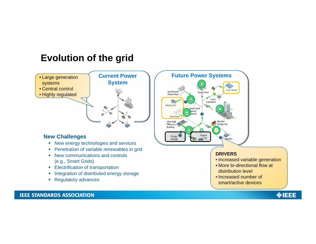
New Challenges New energy technologies and services Penetration of variable renewables in grid New communications and controls
(e.g., Smart Grids) Electrification of transportation Integration of distributed energy storage Regulatory advances
Current Power System
Future Power Systems
Evolution of the grid
• Large generation systems
• Central control• Highly regulated
DRIVERS• Increased variable generation• More bi-directional flow at
distribution level• Increased number of
smart/active devices
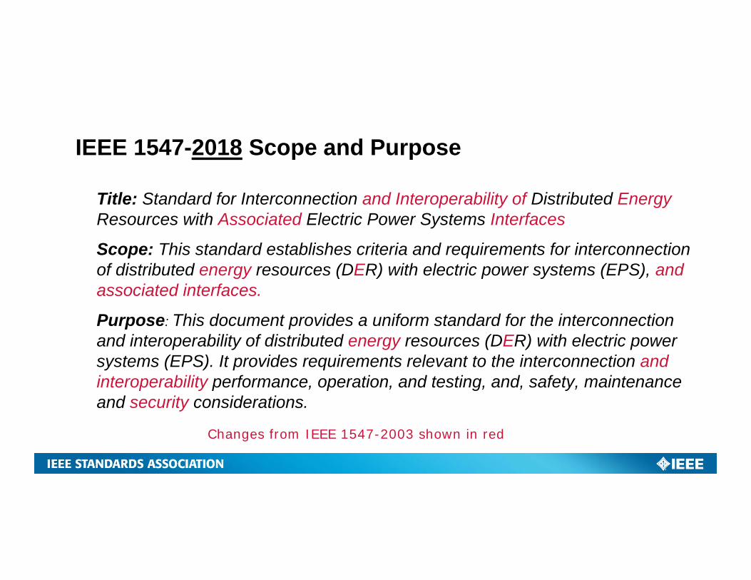
IEEE 1547-2018 Scope and Purpose
Title: Standard for Interconnection and Interoperability of Distributed EnergyResources with Associated Electric Power Systems Interfaces
Scope: This standard establishes criteria and requirements for interconnection of distributed energy resources (DER) with electric power systems (EPS), and associated interfaces.
Purpose: This document provides a uniform standard for the interconnection and interoperability of distributed energy resources (DER) with electric power systems (EPS). It provides requirements relevant to the interconnection and interoperability performance, operation, and testing, and, safety, maintenanceand security considerations.
Changes from IEEE 1547-2003 shown in red
Definition of Distributed Energy Resource
In the context of IEEE 1547:
“A source of electric power that is not directly connected to a bulk power system.”
– Includes distributed generators.
– Includes distributed energy storage technologies.
– Does not include controllable loads used for demand response.
5
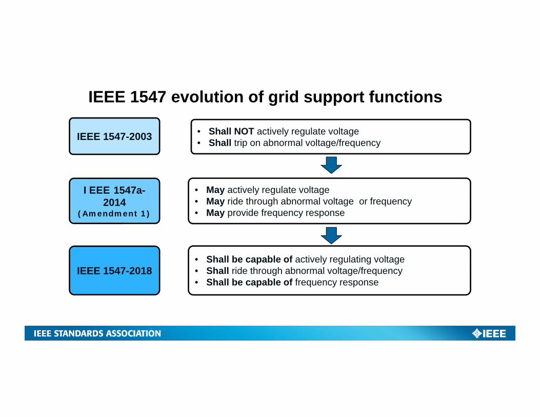
• Shall NOT actively regulate voltage• Shall trip on abnormal voltage/frequency
IEEE 1547 evolution of grid support functions
IEEE 1547-2003
IEEE 1547a-2014
(Amendment 1)
• May actively regulate voltage• May ride through abnormal voltage or frequency• May provide frequency response
IEEE 1547-2018• Shall be capable of actively regulating voltage• Shall ride through abnormal voltage/frequency• Shall be capable of frequency response
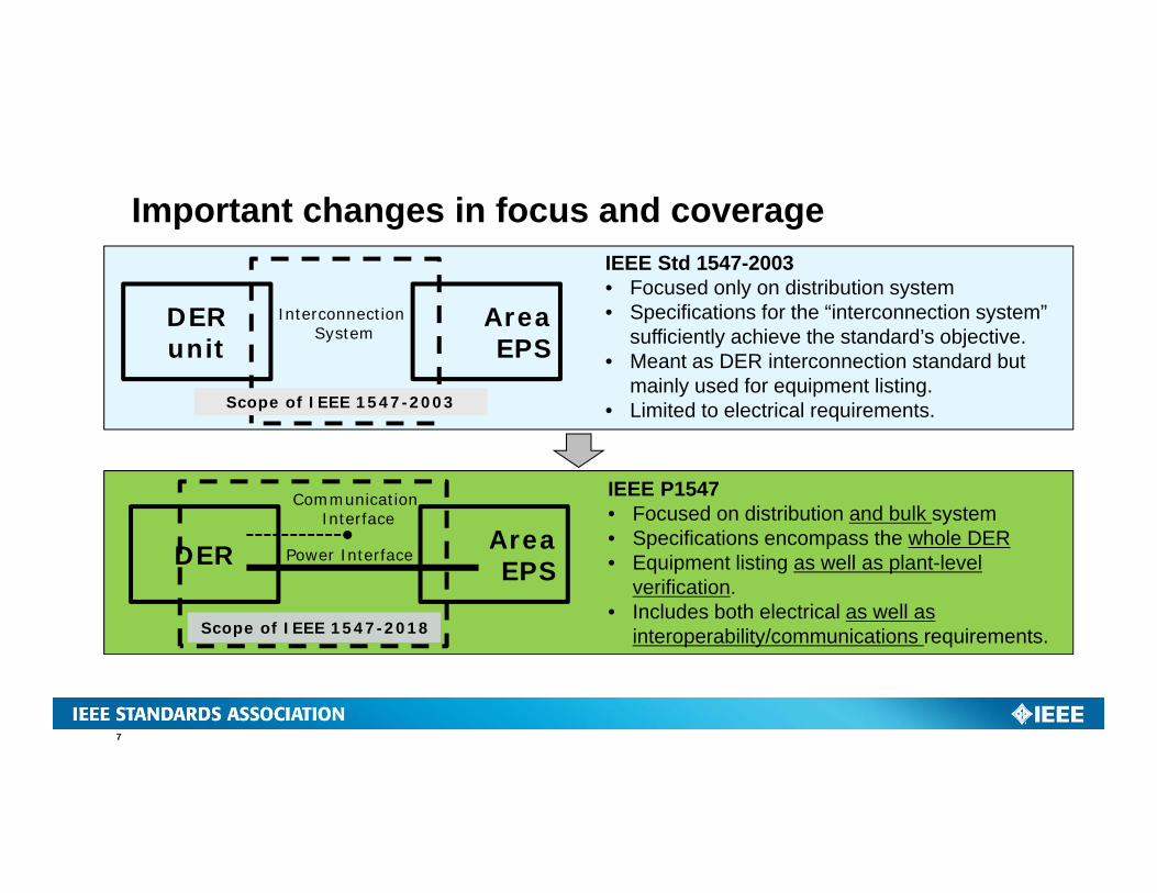
IEEE Std 1547-2003• Focused only on distribution system• Specifications for the “interconnection system”
sufficiently achieve the standard’s objective.• Meant as DER interconnection standard but
mainly used for equipment listing.• Limited to electrical requirements.
Important changes in focus and coverage
Area EPS
Interconnection System
Scope of IEEE 1547-2003
DER unit
IEEE P1547• Focused on distribution and bulk system• Specifications encompass the whole DER• Equipment listing as well as plant-level
verification.• Includes both electrical as well as
interoperability/communications requirements.
Area EPS
Communication Interface
Power Interface
Scope of IEEE 1547-2018
DER
7
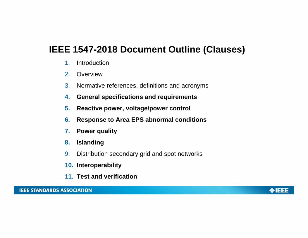
1. Introduction
2. Overview
3. Normative references, definitions and acronyms
4. General specifications and requirements
5. Reactive power, voltage/power control
6. Response to Area EPS abnormal conditions
7. Power quality
8. Islanding
9. Distribution secondary grid and spot networks
10. Interoperability
11. Test and verification
IEEE 1547-2018 Document Outline (Clauses)
General Specifications & Requirements
9
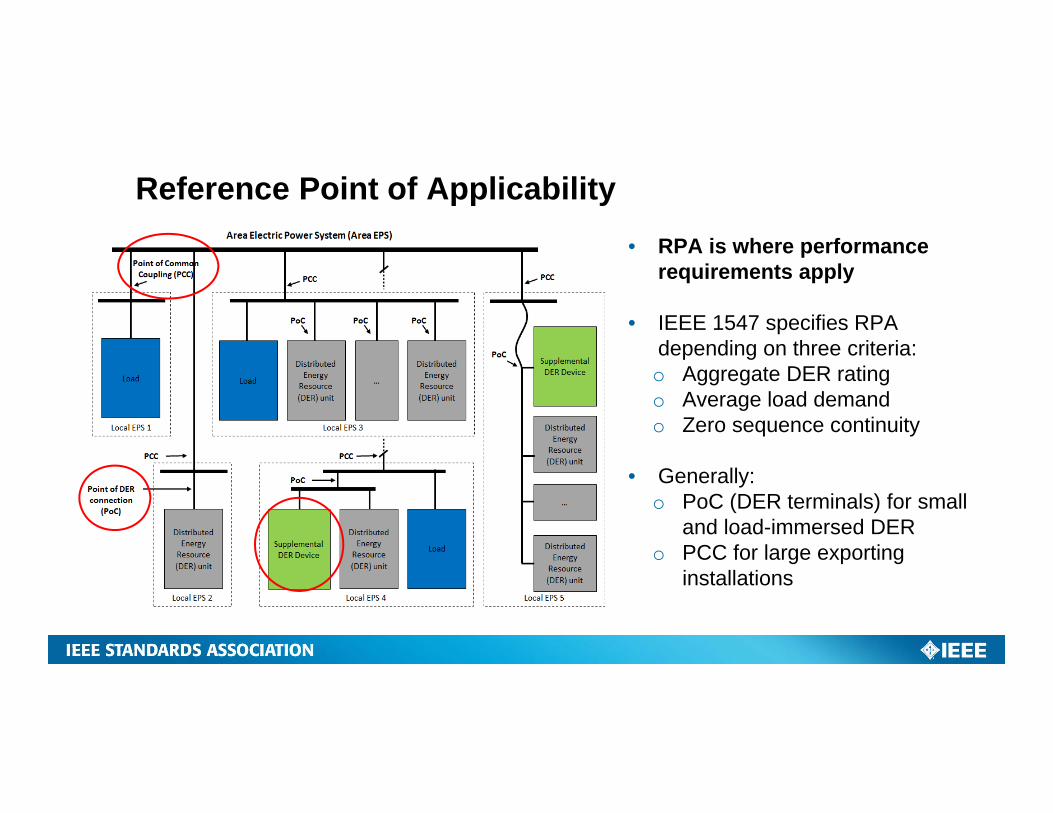
Reference Point of Applicability• RPA is where performance
requirements apply
• IEEE 1547 specifies RPA depending on three criteria:o Aggregate DER ratingo Average load demando Zero sequence continuity
• Generally:o PoC (DER terminals) for small
and load-immersed DERo PCC for large exporting
installations
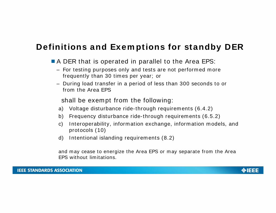
Definitions and Exemptions for standby DERA DER that is operated in parallel to the Area EPS:
– For testing purposes only and tests are not performed more frequently than 30 times per year; or
– During load transfer in a period of less than 300 seconds to or from the Area EPS
shall be exempt from the following:a) Voltage disturbance ride-through requirements (6.4.2)b) Frequency disturbance ride-through requirements (6.5.2)c) Interoperability, information exchange, information models, and
protocols (10)d) Intentional islanding requirements (8.2)
and may cease to energize the Area EPS or may separate from the Area EPS without limitations.
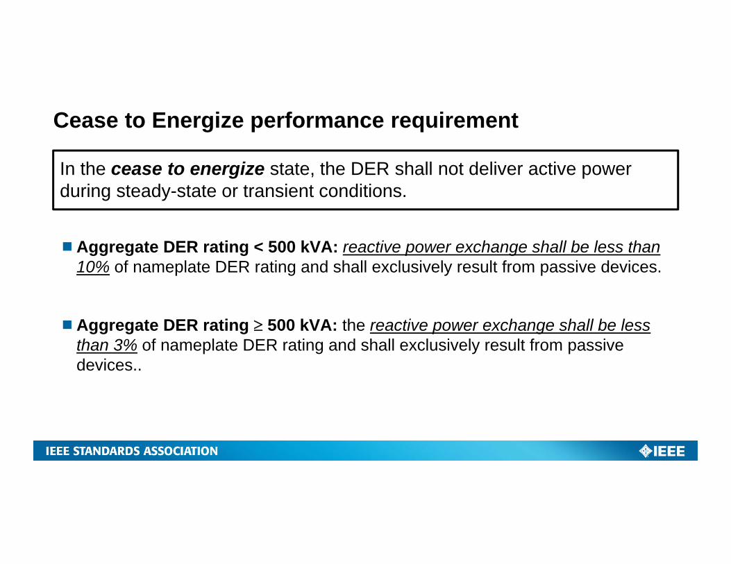
Cease to Energize performance requirement
In the cease to energize state, the DER shall not deliver active power during steady-state or transient conditions.
Aggregate DER rating < 500 kVA: reactive power exchange shall be less than 10% of nameplate DER rating and shall exclusively result from passive devices.
Aggregate DER rating 500 kVA: the reactive power exchange shall be less than 3% of nameplate DER rating and shall exclusively result from passive devices..
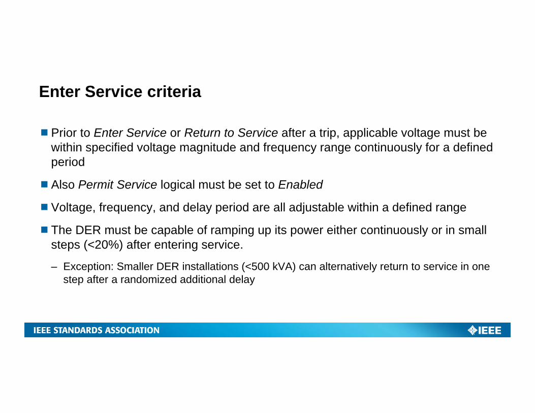
Enter Service criteria
Prior to Enter Service or Return to Service after a trip, applicable voltage must be within specified voltage magnitude and frequency range continuously for a defined period
Also Permit Service logical must be set to Enabled
Voltage, frequency, and delay period are all adjustable within a defined range
The DER must be capable of ramping up its power either continuously or in small steps (<20%) after entering service.
– Exception: Smaller DER installations (<500 kVA) can alternatively return to service in one step after a randomized additional delay
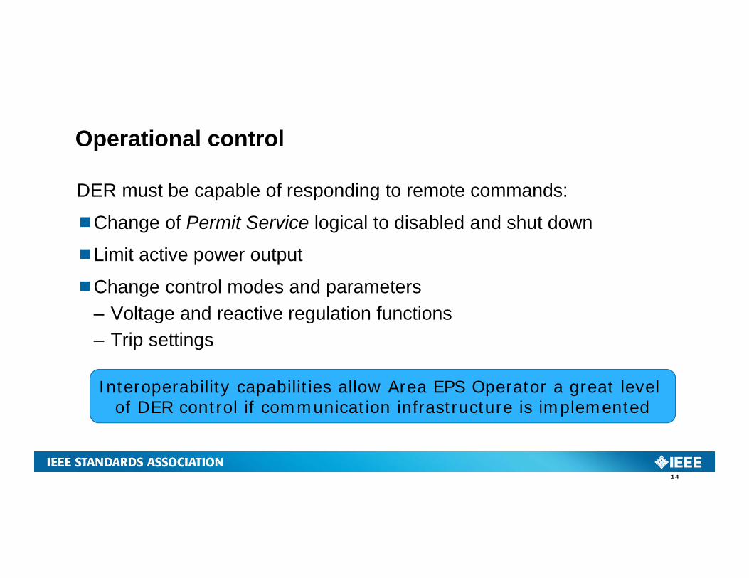
Operational control
DER must be capable of responding to remote commands:
Change of Permit Service logical to disabled and shut down
Limit active power output
Change control modes and parameters– Voltage and reactive regulation functions– Trip settings
14
Interoperability capabilities allow Area EPS Operator a great level of DER control if communication infrastructure is implemented
Reactive power, voltage/power control
15
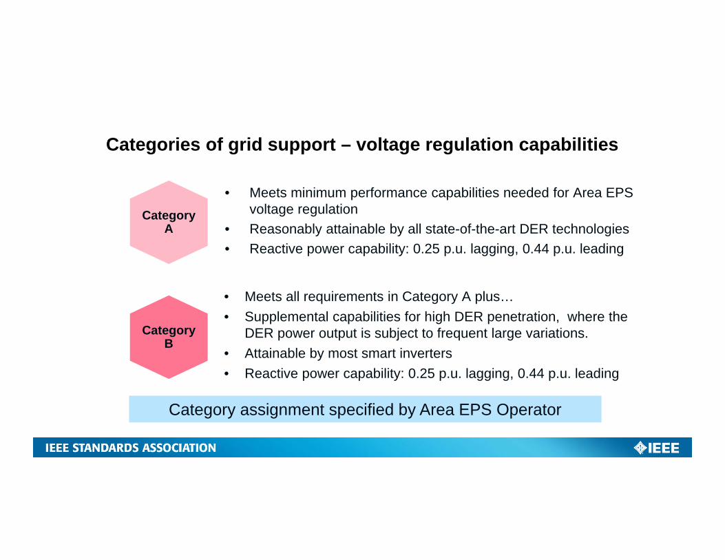
Categories of grid support – voltage regulation capabilities
Category A
• Meets minimum performance capabilities needed for Area EPS voltage regulation
• Reasonably attainable by all state-of-the-art DER technologies• Reactive power capability: 0.25 p.u. lagging, 0.44 p.u. leading
Category B
• Meets all requirements in Category A plus…• Supplemental capabilities for high DER penetration, where the
DER power output is subject to frequent large variations.• Attainable by most smart inverters• Reactive power capability: 0.25 p.u. lagging, 0.44 p.u. leading
Category assignment specified by Area EPS Operator
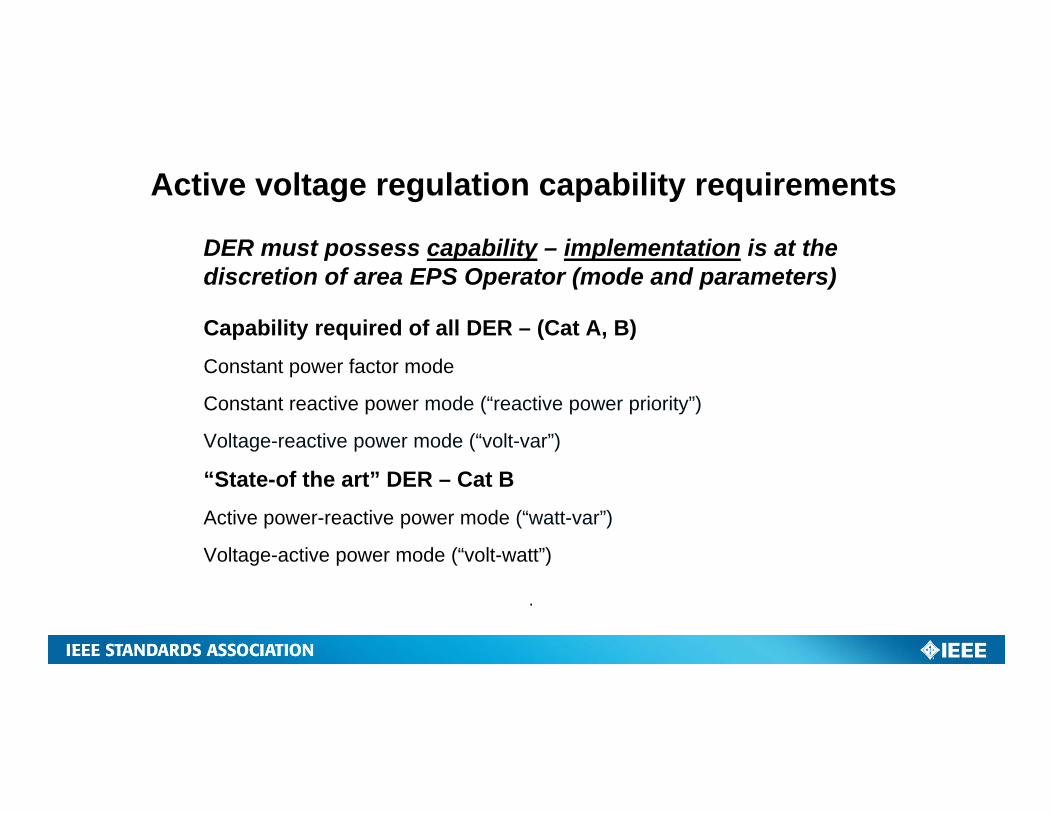
DER must possess capability – implementation is at the discretion of area EPS Operator (mode and parameters)
Capability required of all DER – (Cat A, B)Constant power factor mode
Constant reactive power mode (“reactive power priority”)
Voltage-reactive power mode (“volt-var”)
“State-of the art” DER – Cat BActive power-reactive power mode (“watt-var”)
Voltage-active power mode (“volt-watt”)
.
Active voltage regulation capability requirements
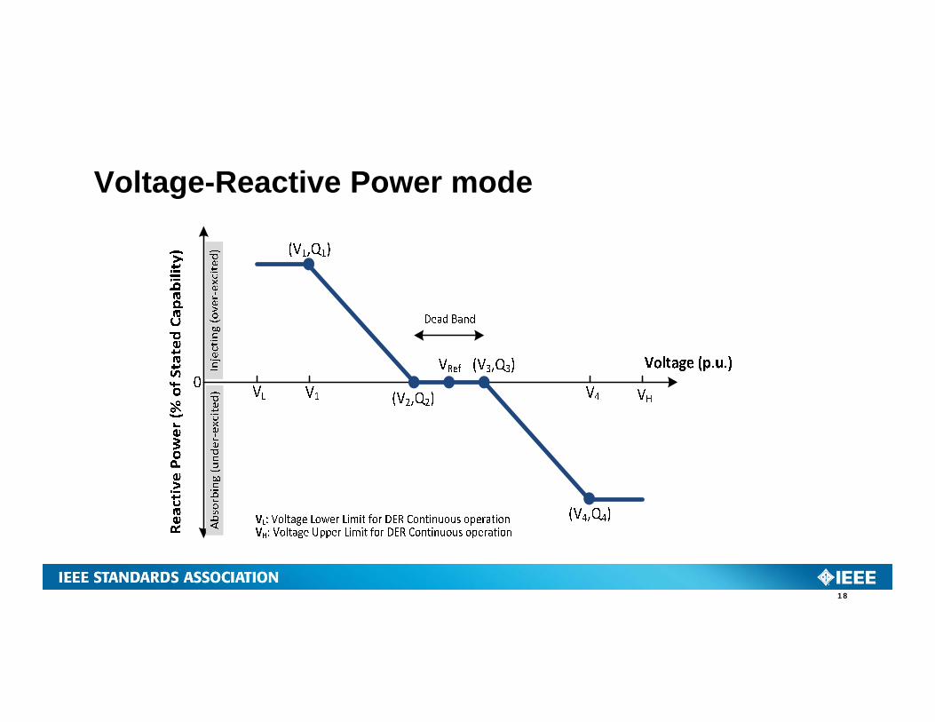
Voltage-Reactive Power mode
18
Response to abnormal conditions
19
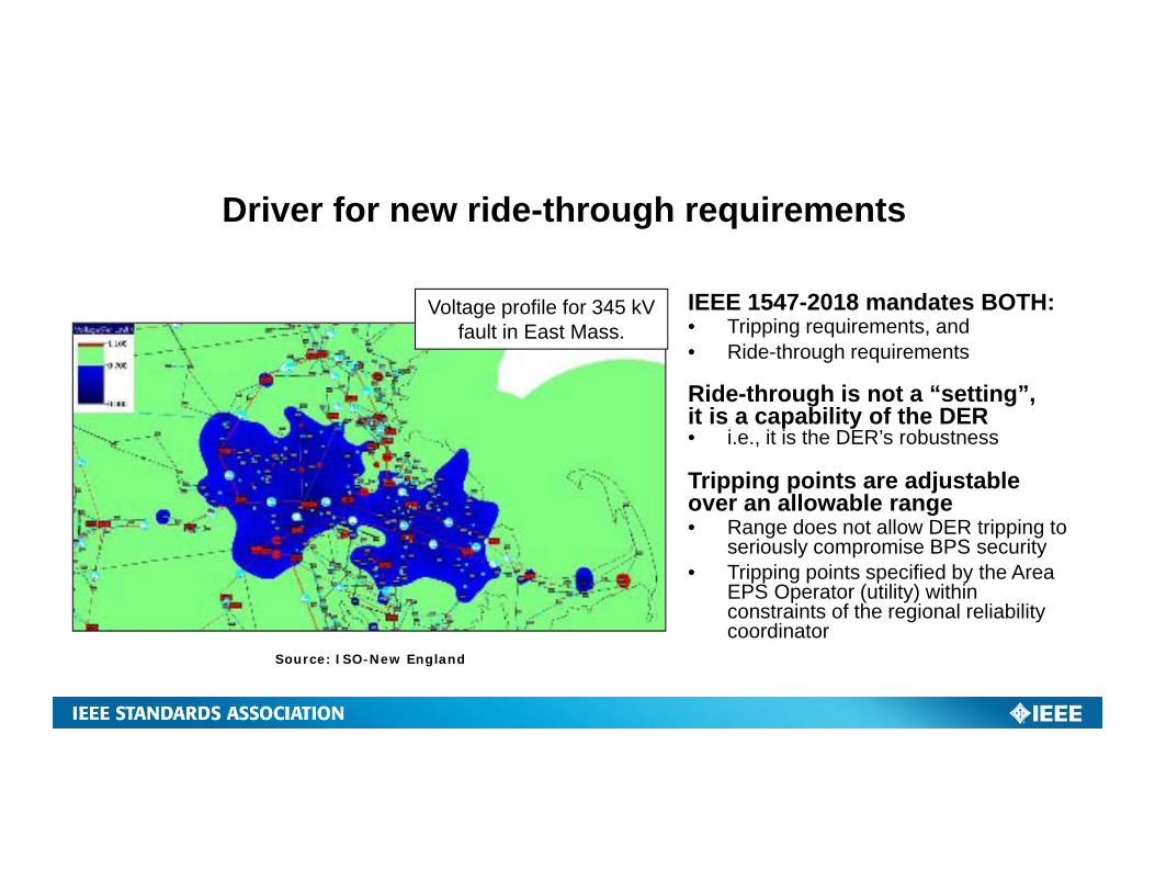
Driver for new ride-through requirements
Voltage profile for 345 kV fault in East Mass.
Source: ISO-New England
IEEE 1547-2018 mandates BOTH:• Tripping requirements, and• Ride-through requirements
Ride-through is not a “setting”, it is a capability of the DER• i.e., it is the DER’s robustness
Tripping points are adjustable over an allowable range• Range does not allow DER tripping to
seriously compromise BPS security• Tripping points specified by the Area
EPS Operator (utility) within constraints of the regional reliability coordinator
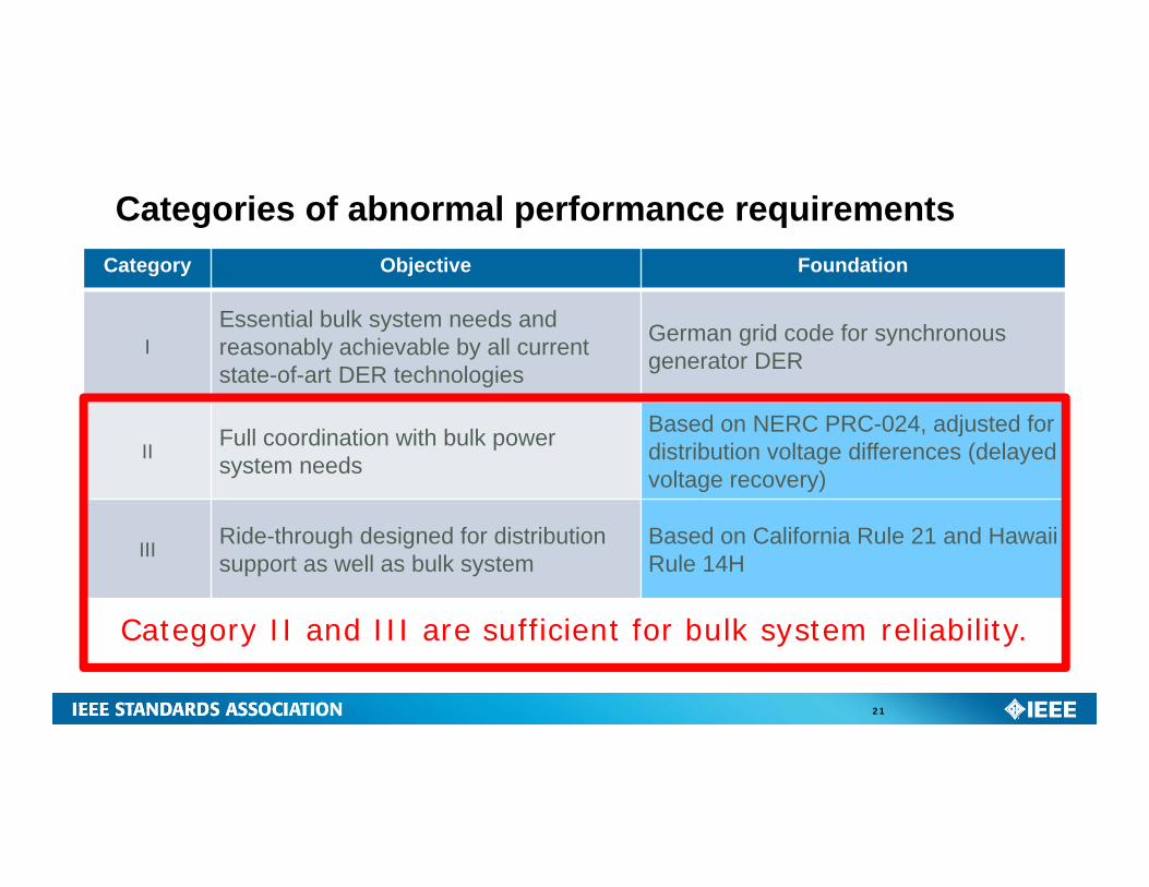
Categories of abnormal performance requirements
21
Category Objective Foundation
IEssential bulk system needs and reasonably achievable by all current state-of-art DER technologies
German grid code for synchronous generator DER
II Full coordination with bulk power system needs
Based on NERC PRC-024, adjusted for distribution voltage differences (delayed voltage recovery)
III Ride-through designed for distribution support as well as bulk system
Based on California Rule 21 and Hawaii Rule 14H
Category II and III are sufficient for bulk system reliability.
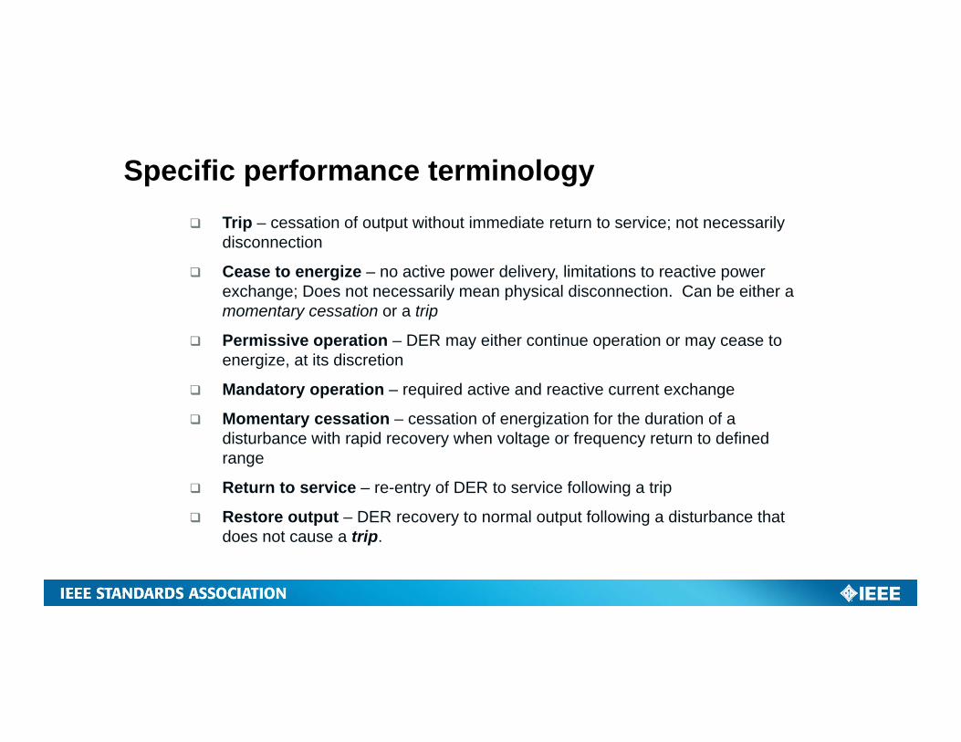
Trip – cessation of output without immediate return to service; not necessarily disconnection
Cease to energize – no active power delivery, limitations to reactive power exchange; Does not necessarily mean physical disconnection. Can be either a momentary cessation or a trip
Permissive operation – DER may either continue operation or may cease to energize, at its discretion
Mandatory operation – required active and reactive current exchange
Momentary cessation – cessation of energization for the duration of a disturbance with rapid recovery when voltage or frequency return to defined range
Return to service – re-entry of DER to service following a trip
Restore output – DER recovery to normal output following a disturbance that does not cause a trip.
Specific performance terminology
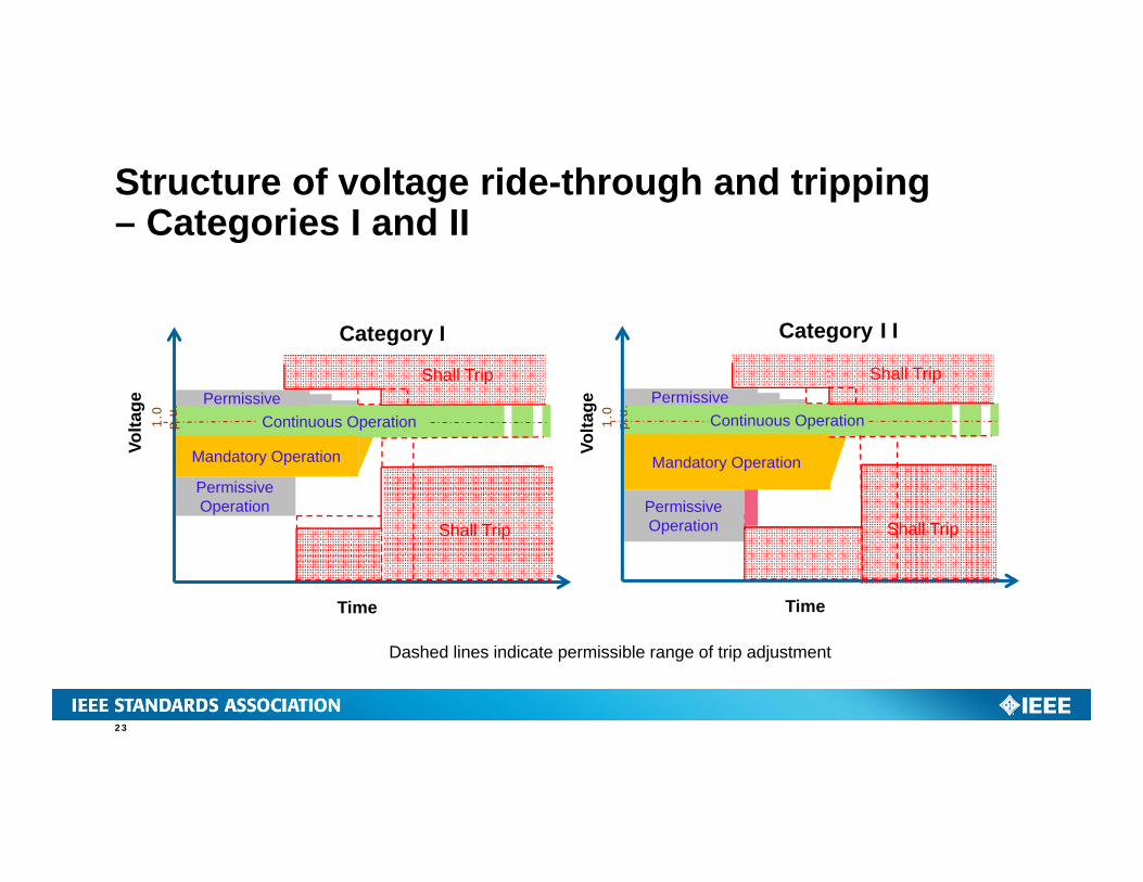
Structure of voltage ride-through and tripping– Categories I and II
Volta
ge
Continuous Operation
Mandatory Operation
Permissive Operation
Time
Volta
ge Permissive
Shall Trip
Shall Trip
Category I
Continuous Operation
Mandatory Operation
Permissive Operation
Time
Permissive
Shall Trip
Shall Trip
1.0
p.u.
Category II
1.0
p.u.
Dashed lines indicate permissible range of trip adjustment
23
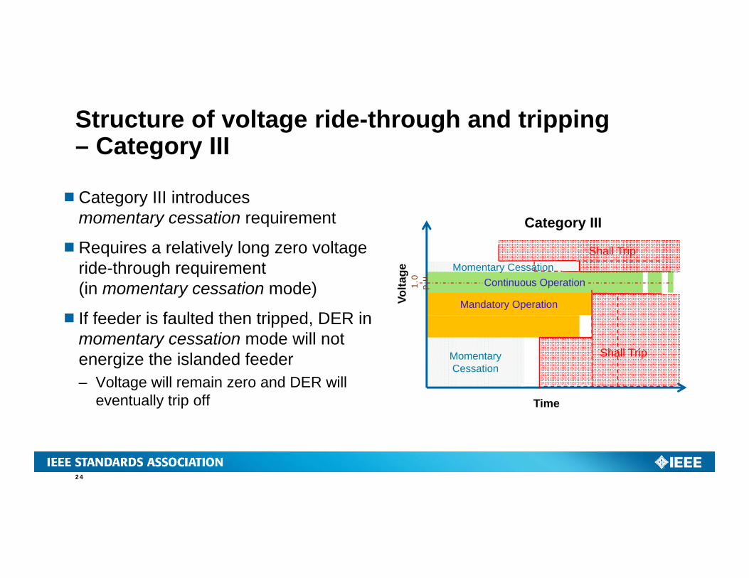
Category III introduces momentary cessation requirement
Requires a relatively long zero voltage ride-through requirement (in momentary cessation mode)
If feeder is faulted then tripped, DER in momentary cessation mode will not energize the islanded feeder– Voltage will remain zero and DER will
eventually trip off
Continuous Operation
Momentary Cessation
Time
Momentary Cessation
Shall Trip
Shall Trip
Category III
Mandatory OperationVolta
ge1.
0 p.
u.
24
Structure of voltage ride-through and tripping– Category III
Voltage disturbances within continuous operating range
DER must remain in operation for any voltage disturbances in which voltage magnitude remains within C84.1 Range B.– E.g., abrupt steps of voltage up or down could be such a disturbance
DER must deliver available active power as great as the pre-disturbance level (prorated by per-unit voltage if voltage is less than nominal)– Temporary deviations of active power < 0.5 seconds allowed
Exceptions for unbalance:– Negative sequence voltage (V2) > 5% for duration > 60 s.– Negative sequence voltage (V2) > 3% for duration > 300 s.
25
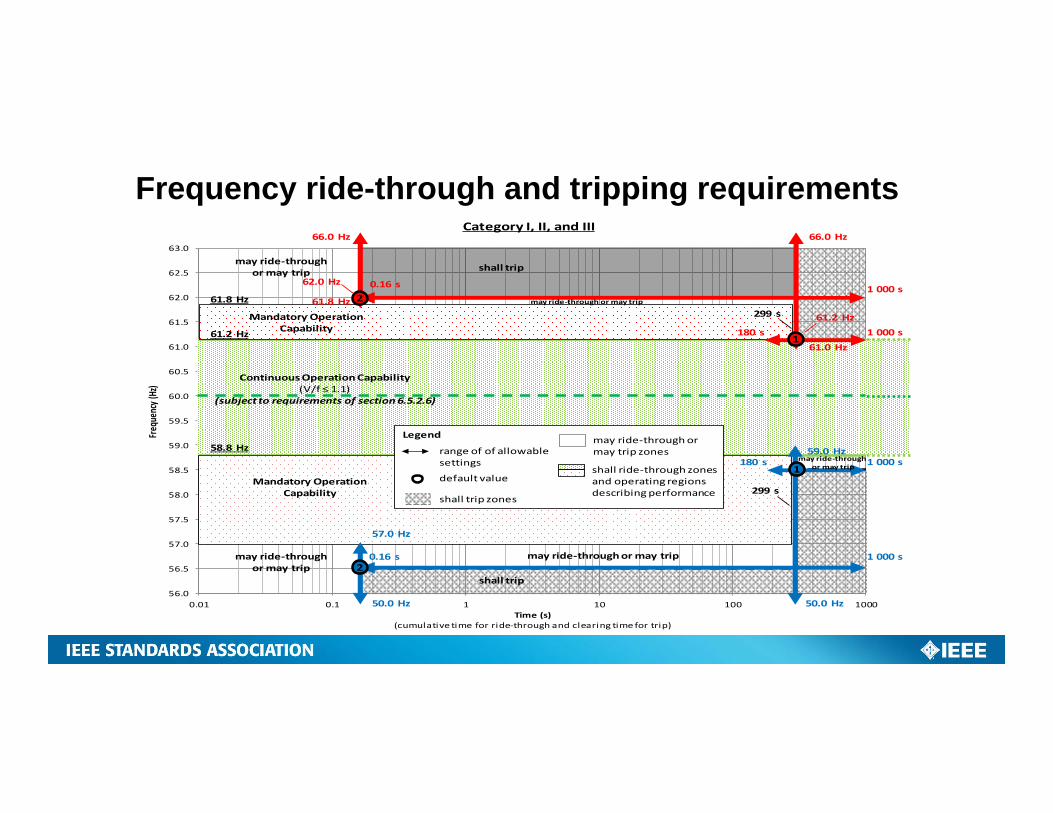
Frequency ride-through and tripping requirements
56.0
56.5
57.0
57.5
58.0
58.5
59.0
59.5
60.0
60.5
61.0
61.5
62.0
62.5
63.0
0.01 0.1 1 10 100 1000
Freq
uency (
Hz)
Time (s)(cumulative time for ride‐through and clearing time for trip)
Continuous OperationCapability(V/f ≤ 1.1)
(subject to requirements of section 6.5.2.6)
Mandatory OperationCapability
Mandatory OperationCapability
shall trip
shall trip
66.0 Hz 66.0 Hz
1 000 s0.16 s
180 s
61.8 Hz
50.0 Hz
0.16 s 1 000 s
50.0 Hz
57.0 Hz
1 000 s180 s1
2
2
161.0 Hz
1 000 s
59.0 Hz
Legend
range of of allowable settings
default value
shall trip zones
may ride‐through ormay trip zones
shall ride‐through zonesand operating regionsdescribing performance
may ride‐throughormay trip
may ride‐throughor may trip
may ride‐through or may trip
Category I, II, and III
299 s
299 s
61.2 Hz
may ride‐through or may trip
61.8 Hz
58.8 Hz
62.0 Hz
61.2 Hz
may ride‐throughor may trip
Other ride-through requirements
Consecutive voltage disturbances, e.g.:– Voltage dips caused by multiple unsuccessful reclosing attempts on another circuit– Dynamic voltage swings in and out of normal range following bulk system fault– Repetitive faults
Rate-of-change of frequency (ROCOF)– Severe bulk grid dynamic events
Phase angle jumps, e.g.:– Unbalanced faults– Bulk system switching events (generator trip, line switching, etc.)
27
Frequency response
Increasing penetration of unconventional generation is reducing system inertia which can degrade system frequency stability
Frequency droop (governor-like) response required of all DER– Active power output is modulated in response to frequency deviation– No mandate to maintain headroom to increase active power to provide
under-frequency response
Frequency response parameters:– Default droop 0.05 p.u. frequency for one p.u. active power change– Default deadband 36 mHz– Other parameter settings allowed as approved by the regional reliability coordinator
28

Power Quality
29
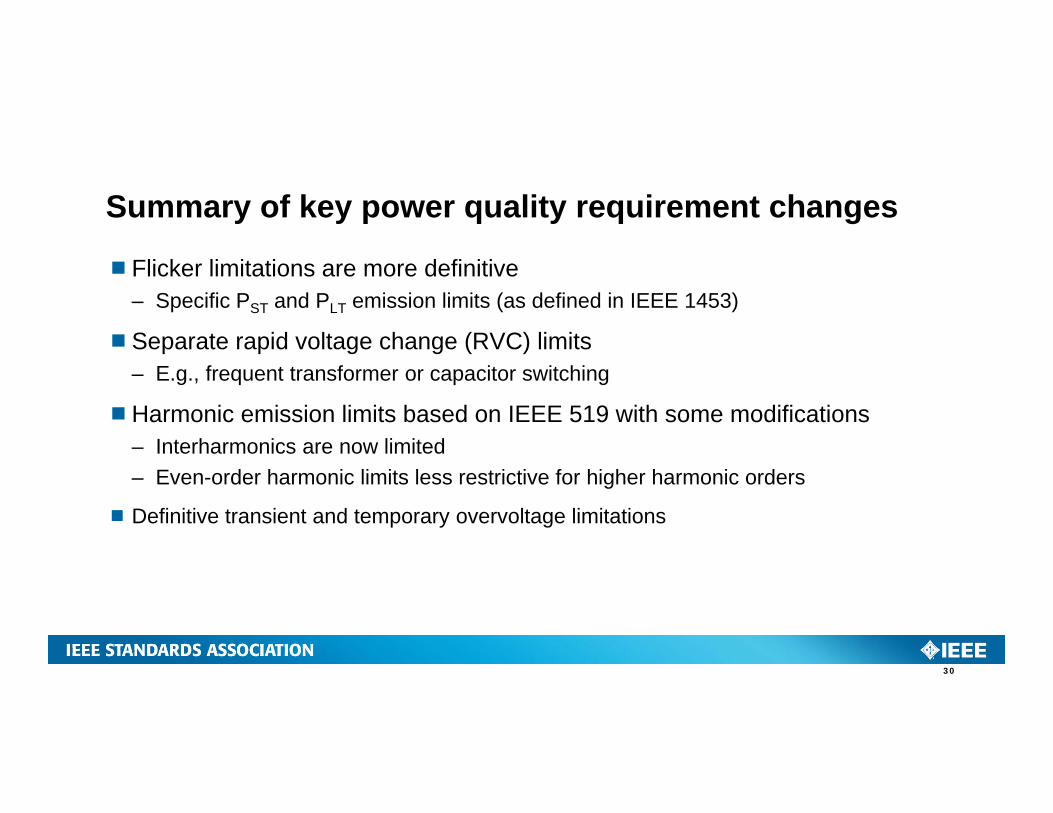
Summary of key power quality requirement changes
Flicker limitations are more definitive– Specific PST and PLT emission limits (as defined in IEEE 1453)
Separate rapid voltage change (RVC) limits– E.g., frequent transformer or capacitor switching
Harmonic emission limits based on IEEE 519 with some modifications– Interharmonics are now limited– Even-order harmonic limits less restrictive for higher harmonic orders
Definitive transient and temporary overvoltage limitations
30
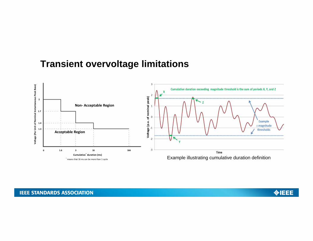
2
Volta
ge (P
er Unit o
f Nom
inal In
stan
tane
ous P
eak Ba
se)
Cumulative* duration (ms)
1.7
1.4
1.3
1.6 3 16 166
Acceptable Region
Non‐ Acceptable Region
0
* means that 16 ms can be more than 1 cycle
Transient overvoltage limitations
Example illustrating cumulative duration definition
Islanding
32
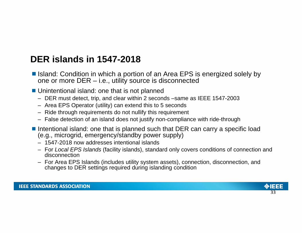
DER islands in 1547-2018 Island: Condition in which a portion of an Area EPS is energized solely by
one or more DER – i.e., utility source is disconnectedUnintentional island: one that is not planned
– DER must detect, trip, and clear within 2 seconds –same as IEEE 1547-2003– Area EPS Operator (utility) can extend this to 5 seconds – Ride through requirements do not nullify this requirement– False detection of an island does not justify non-compliance with ride-through
Intentional island: one that is planned such that DER can carry a specific load (e.g., microgrid, emergency/standby power supply)– 1547-2018 now addresses intentional islands– For Local EPS Islands (facility islands), standard only covers conditions of connection and
disconnection– For Area EPS Islands (includes utility system assets), connection, disconnection, and
changes to DER settings required during islanding condition
33
Interoperability
34
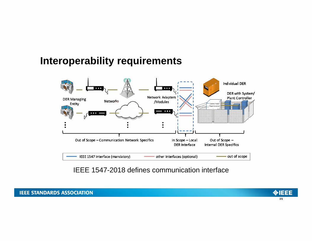
IEEE 1547-2018 defines communication interface
Interoperability requirements
35
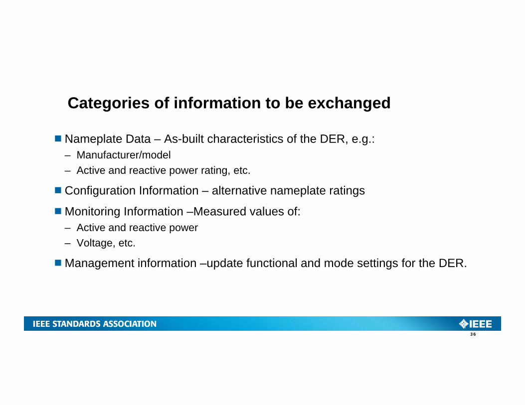
Nameplate Data – As-built characteristics of the DER, e.g.:– Manufacturer/model– Active and reactive power rating, etc.
Configuration Information – alternative nameplate ratings
Monitoring Information –Measured values of:– Active and reactive power– Voltage, etc.
Management information –update functional and mode settings for the DER.
Categories of information to be exchanged
36
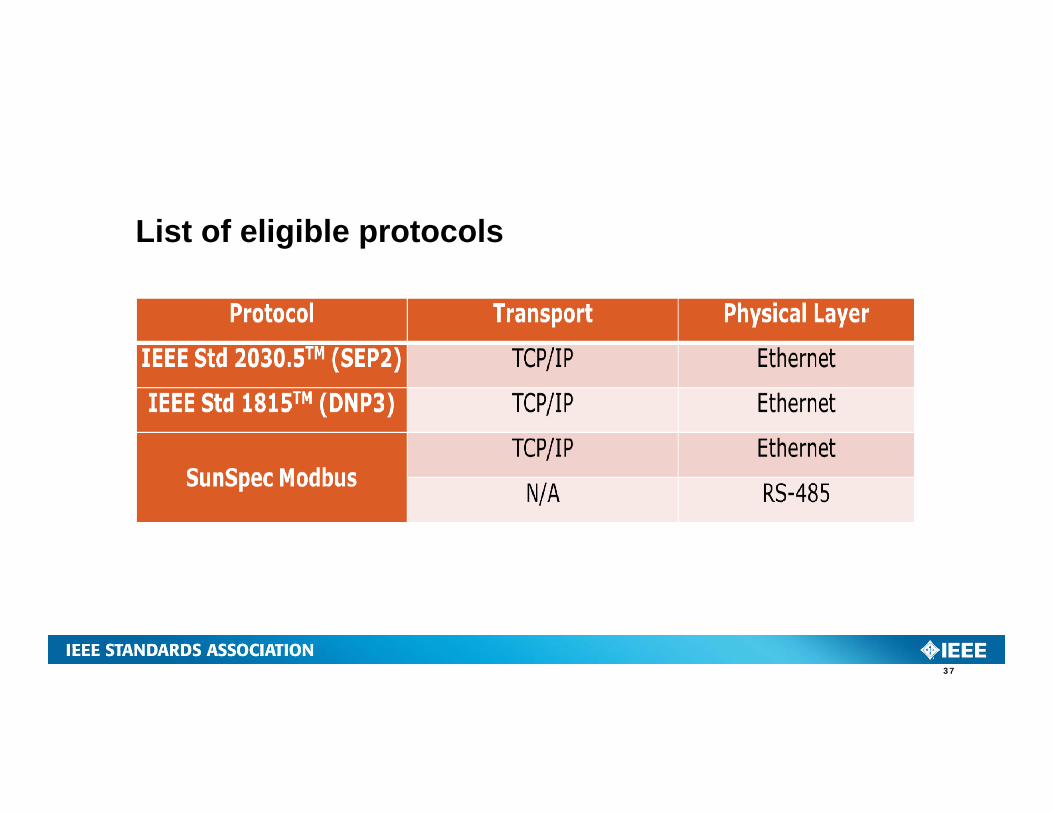
List of eligible protocols
37
Testing and Verification
38
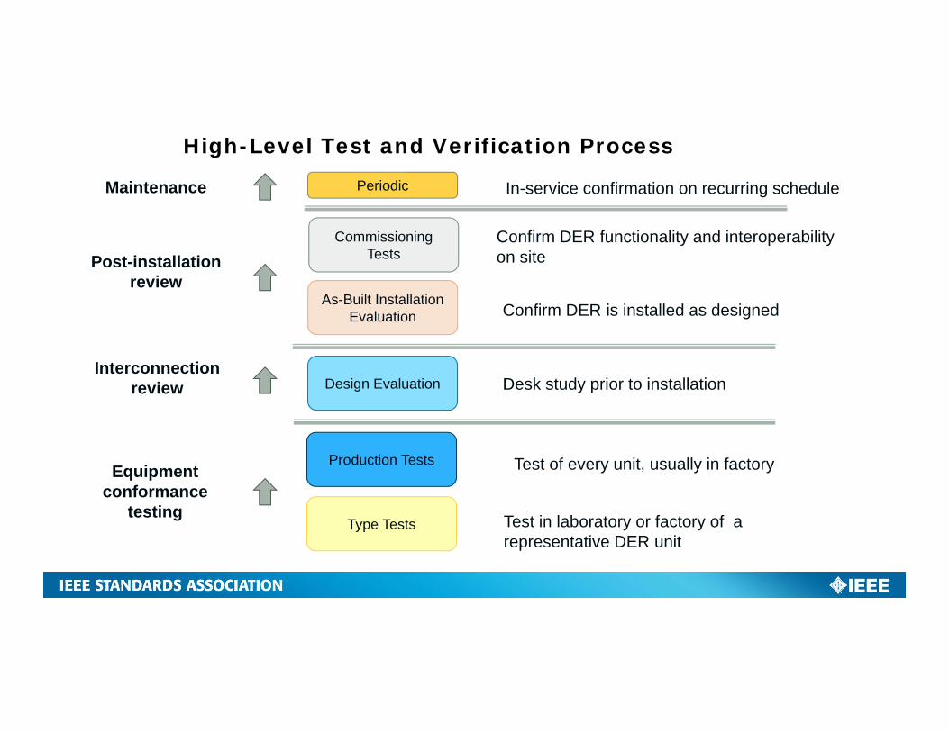
High-Level Test and Verification Process
Type Tests Test in laboratory or factory of a representative DER unit
Design EvaluationInterconnection
review
Equipment conformance
testing
As-Built Installation Evaluation
Post-installationreview
Production Tests
Commissioning Tests
PeriodicMaintenance
Test of every unit, usually in factory
Desk study prior to installation
Confirm DER is installed as designed
Confirm DER functionality and interoperability on site
In-service confirmation on recurring schedule
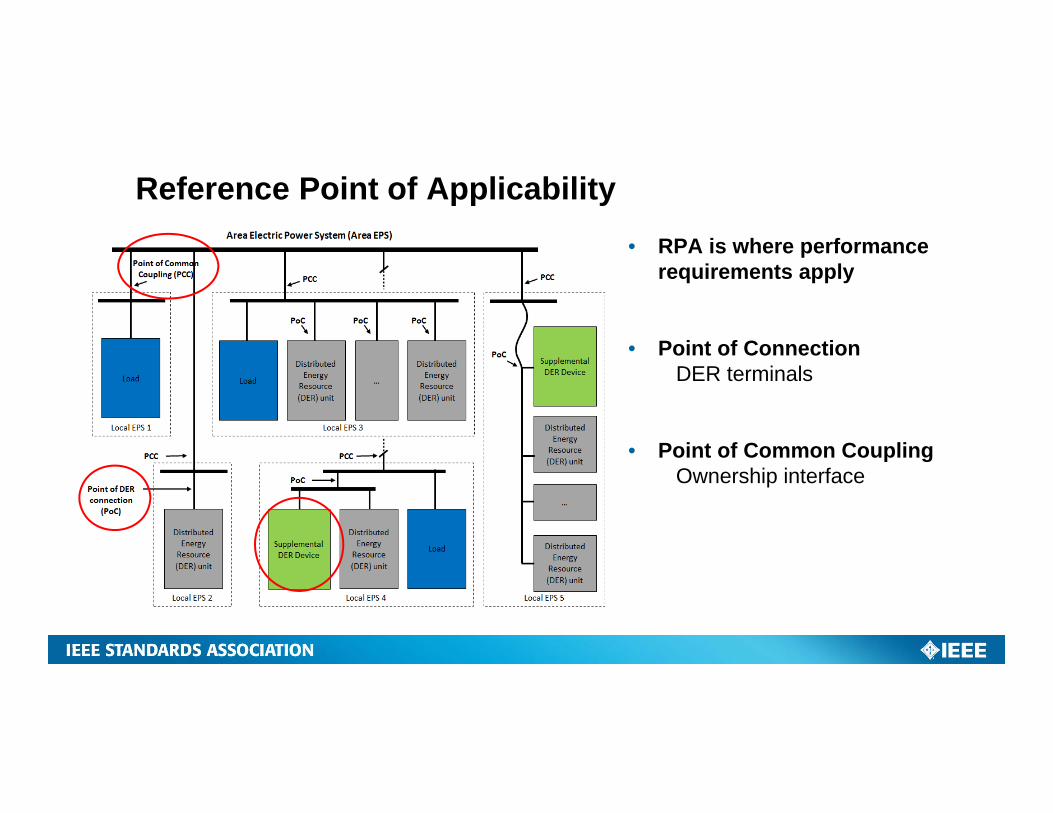
Reference Point of Applicability• RPA is where performance
requirements apply
• Point of ConnectionDER terminals
• Point of Common CouplingOwnership interface
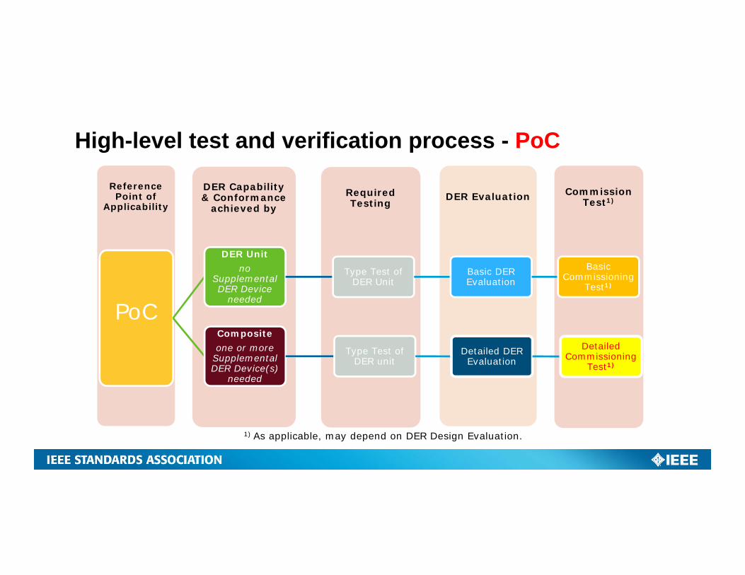
High-level test and verification process - PoC
Commission Test1)DER EvaluationRequired
TestingDER Capability & Conformance
achieved by
Reference Point of
Applicability
PoC
DER Unitno
Supplemental DER Device
needed
Type Test of DER Unit
Basic DER Evaluation
Basic Commissioning
Test1)
Compositeone or more
Supplemental DER Device(s)
needed
Type Test of DER unit
Detailed DER Evaluation
Detailed Commissioning
Test1)
1) As applicable, may depend on DER Design Evaluation.
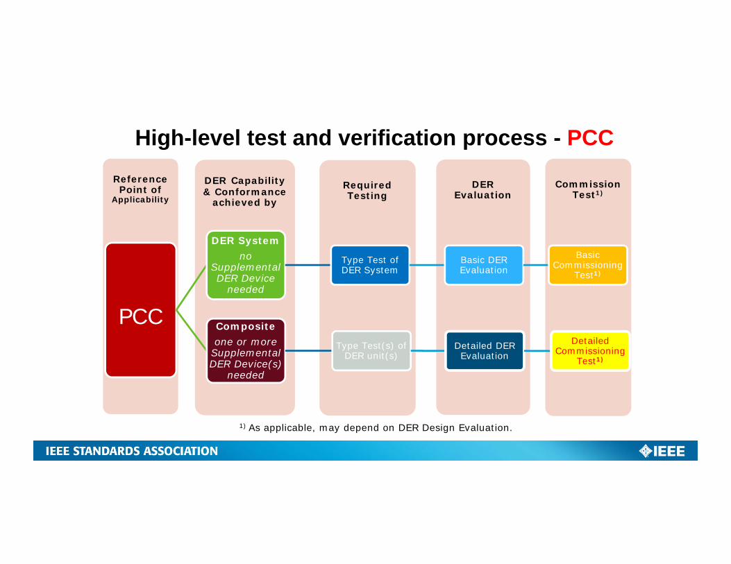
High-level test and verification process - PCC
Commission Test1)
DER Evaluation
Required Testing
DER Capability & Conformance
achieved by
Reference Point of
Applicability
PCC
DER Systemno
Supplemental DER Device
needed
Type Test of DER System
Basic DER Evaluation
Basic Commissioning
Test1)
Compositeone or more
Supplemental DER Device(s)
needed
Type Test(s) of DER unit(s)
Detailed DER Evaluation
Detailed Commissioning
Test1)
1) As applicable, may depend on DER Design Evaluation.
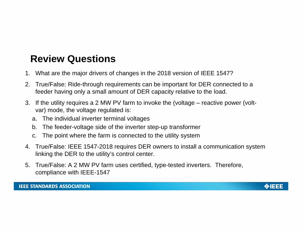
Review Questions1. What are the major drivers of changes in the 2018 version of IEEE 1547?
2. True/False: Ride-through requirements can be important for DER connected to a feeder having only a small amount of DER capacity relative to the load.
3. If the utility requires a 2 MW PV farm to invoke the (voltage – reactive power (volt-var) mode, the voltage regulated is:
a. The individual inverter terminal voltagesb. The feeder-voltage side of the inverter step-up transformerc. The point where the farm is connected to the utility system
4. True/False: IEEE 1547-2018 requires DER owners to install a communication system linking the DER to the utility’s control center.
5. True/False: A 2 MW PV farm uses certified, type-tested inverters. Therefore, compliance with IEEE-1547
Backup Slides
45
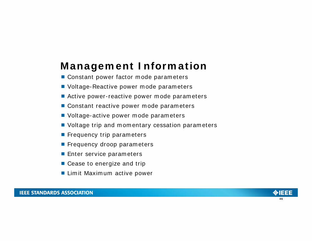
Constant power factor mode parameters Voltage-Reactive power mode parameters Active power-reactive power mode parameters Constant reactive power mode parameters Voltage-active power mode parameters Voltage trip and momentary cessation parameters Frequency trip parameters Frequency droop parameters Enter service parameters Cease to energize and trip Limit Maximum active power
Management Information
46