doe amr review - us department of energy project overview timeline •project start –dec. 11, 2014...
TRANSCRIPT
DOE AMR ReviewCree, Inc., EE0006920 “88 Kilowatt Automotive Inverter with New 900 Volt Silicon Carbide MOSFET Technology”
June 9, 2015Jeff Casady, Cree Business Development & Program Manager
Jeff Casady, Vipindas Pala, Brett Hull, Scott Allen, John Palmour, Craig Capell, Don Gajewski - Cree, Inc.Kraig Olejniczak, Ty McNutt – APEI, Inc.
Chingchi Chen, Ming Su – Ford Motor Company
Project ID #EDT073
This presentation does not contain any proprietary, confidential, or otherwise restricted information

2
Project Overview
Timeline
• Project Start – Dec. 11, 2014• Project Complete – Dec. 10, 2016• 5% Complete
Barriers
• Cost (A) – Target < $8/kW by 2020• Weight (C) – SiC expected to improve power density (>1.4kW/kg by 2020)• Reliability & Lifetime (D) – SiC ↓ FIT 10x• Efficiency (E) – SiC expected to improve light-load efficiency and vehicle range
Budget
• Govt. Share: $1,937,752.00• Cost Share : $2,107,744.00• Total : $4,045,496.00
Partners and Subcontractors
• Cree, Inc. lead; 900V SiC power MOSFET• APEI – sub; SiC power modules & inverter• Ford – sub; SiC evaluation and feedback
3
Relevance of program targets at macro level
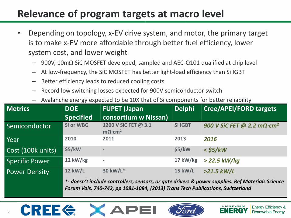
• Depending on topology, x-EV drive system, and motor, the primary target is to make x-EV more affordable through better fuel efficiency, lower system cost, and lower weight
– 900V, 10mΩ SiC MOSFET developed, sampled and AEC-Q101 qualified at chip level– At low-frequency, the SiC MOSFET has better light-load efficiency than Si IGBT– Better efficiency leads to reduced cooling costs– Record low switching losses expected for 900V semiconductor switch– Avalanche energy expected to be 10X that of Si components for better reliability
Metrics DOE Specified
FUPET (Japan consortium w Nissan)
Delphi Cree/APEI/FORD targets
Semiconductor Si or WBG 1200 V SiC FET @ 3.1 mΩ·cm2
Si IGBT 900 V SiC FET @ 2.2 mΩ·cm2
Year 2010 2011 2013 2016
Cost (100k units) $5/kW - $5/kW < $5/kW
Specific Power 12 kW/kg - 17 kW/kg > 22.5 kW/kg
Power Density 12 kW/L 30 kW/L* 15 kW/L >21.5 kW/L*- doesn’t include controllers, sensors, or gate drivers & power supplies. Ref Materials Science Forum Vols. 740-742, pp 1081-1084, (2013) Trans Tech Publications, Switzerland

4
900V, 10 mΩSiC MOSFET
sampling (2015)
900V MOSFET chip & module benchmark in 88 kW traction inverter & chip
qualification (2016)
Vehicle prototype &
design* (2017)
Vehicle qualification
(2018-20)
Vehicle Mass Production in 2020-22 MY (Fall 2019)
EE0006920 “88 kW Automotive Inverter with New 900V SiC MOSFET Technology”
AEC-Q101 qualified & released 900V SiC MOSFETs available for automotive design & production
Relevance to Commercialization
* Prototype vehicles already demonstrated utilizing Cree SiC MOSFETs by major Tier One automotive OEM in 2014, but not with automotive qualified, 900V components. Additional qualification beyond AEC-Q101 also needed.* Cree SiC diodes already in MP by multiple OEMs for chargers by 2014.

5
Budget Period Start/End Date Milestone Type Description Status
1 12/15/2014 –12/14/2015
Characterization of third optimization of wafer lot of 900
V SiC MOSFET.
Go/No-Go
Test the third power MOSFET lot and measure performance
against the target specifications.
On-track. First 900V, 10mΩSiC MOSFET lot in fab with
ECD of
2 12/15/2015 –12/14/2016
Single-phasetraction drive
demonstration.Technical
Perform single-phase traction drive demo using 900V, 200A, ½ bridge power modules and
evaluate impact of SiCperformance on automotive
traction drive system.
Not started. This is for FY16.
Milestones
• Interim Milestones are defined in the SOPO and PMP

6
ApproachTask # 900V, 10mΩ SiC MOSFET development & qual Wafers Start ECD1 .1 Die centering – lot #1 9 Feb 2015 June 2015
1.1 RDSON vs tSC - lot #2 6 Sept 2015
1.1 Re-center lot based on feedback (Go / No-go milestone) – lot #3 6 Nov 2015
1.2 Pre-qual lot – lot #4 6 Jan 2016
1.2 Qualification Lot #1 – lot #5 12 Mar 2016
2.1 Qualification Lot #2 – lot #6 12 Apr 2016
2.1 Qualification Lot #3 – lot #7 12 May 2016
2.1 Qualify 900V, 10mΩ SiC MOSFET chip by AEC-Q101 standards --- Nov 2016
Task # 900V ½ bridge power module develop & qual Modules Start ECD1 .3 Assemble, characterize and benchmark power modules (900V, >200A, ½ bridge) 6 June 2015 Sept 2015
2.2 Assemble, characterize and benchmark power modules (900V, >200A, ½ bridge) 70 May 2016 Aug 2016
2.2 Qualification of module using a mix of JEDEC and AEC-Q101 standards --- Aug 2016 Dec 2016
Task # 88kW peak traction drive demo Modules Start ECD2.3 Single phase traction drive demo 5 June 2015 Sept 2015
2.3 Three phase traction drive demo 25 May 2016 Aug 2016
2.3 Benchmark 900V SiC based technology with competing technologies --- Aug 2016 Dec 2016

7
Approach - 900V, 10 mΩ SiC MOSFET Estimated RDSON vs T
9.0
9.5
10.0
10.5
11.0
11.5
12.0
12.5
13.0
13.5
14.0
14.5
15.0
15.5
16.0
-50 -25 0 25 50 75 100 125 150 175
On
Resi
stan
ce, R
DS O
n(m
Ω)
Junction Temperature, TJ (°C)
Conditions:IDS = 130 AVGS = 15 Vtp < 200 µs

8
Approach – MOSFET Qualification Plan at 175 °C• Die to be qualified at a TJ,Max of 175 °C under this program• Reliability at 200 °C will be investigated; qualifying at 200 °C will be a stretch goal• AECQ101 die level qualification tests in TO-247
Test Stress Conditions Duration Wafer lots sampled
Total devices sampled
HTGB VGS = 18 V, VDS = 0, Ta=175 °C 1000 hrs 3 231
H3TRB 85 °C, 85% RH, VDS = 100 V, VGS=0 1000 hrs 3 231
HTRB VDS = 720 V, VGS = 0, Ta = 175 °C 1000 hrs 3 231
TC -55 °C / +175 °C, JESD22-A104 condition H, soak mode 1 1000 cycles 3 231
IOL 5 min on / 5 mins off, ∆Tj ≥ 100 °C, Tmax ≥ 175 °C 6000 cycles 3 231
ESD-HBM Classification at 25 °C n/a 1 5
ESD-MM Classification at 25 °C n/a 1 5
ESD-CDM Classification at 25 °C n/a 1 5
9
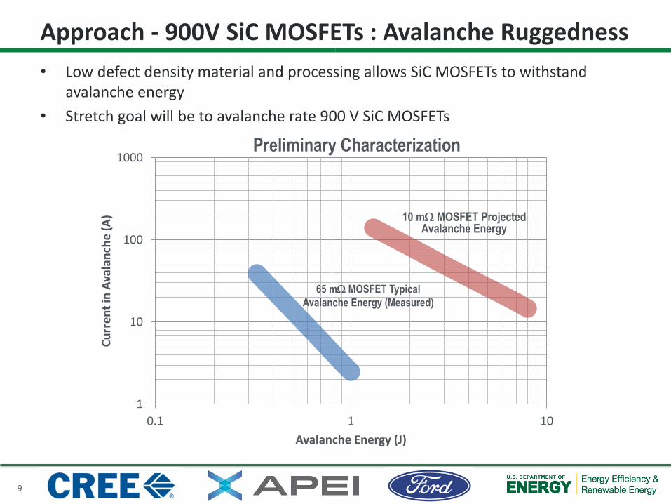
• Low defect density material and processing allows SiC MOSFETs to withstand avalanche energy
• Stretch goal will be to avalanche rate 900 V SiC MOSFETs
Approach - 900V SiC MOSFETs : Avalanche Ruggedness
1
10
100
1000
0.1 1 10
Curr
ent i
n Av
alan
che
(A)
Avalanche Energy (J)
65 mΩ MOSFET TypicalAvalanche Energy (Measured)
10 mΩ MOSFET ProjectedAvalanche Energy
Preliminary Characterization

10
• Target applications– ON-board EV chargers– Switch mode power supplies– Solar inverters– High power DC/DC converters
• AECQ101 qualification effort in progress– Expected to be completed in Q2 2015
• Commercial release planned in 2015
Technical Accomplishment - 900V, 65mΩ SiC MOSFET
100mm 900V, 65 mΩ SiC MOSFET wafer

11
• 900V, 65 mΩ JEDEC Qualification Status (TO-247 Package)• Qualification complete
Technical Accomplishment – 150°C JEDEC qualification

12
• Full turn-ON achieved at +15 V Gate Bias – Convenient gate drive using commercial IGBT and MOSFET drivers.
0
5
10
15
20
25
30
0 1 2 3 4 5 6
I DS
(Am
ps)
VDS(V)
5 V
7 V
9 V
11 V13 V15 V
0 V 0
5
10
15
20
0 5 10 15 20
I DS
(Am
ps)
VGS(V)
25 °C
100 °C
150 °C
VDS = 1V
Output Characteristics at 25 °C Transfer Characteristics
Technical Accomplishment – smaller chip demonstrated

13
• 900V SiC MOSFET has a low temperature coefficient of resistance compared to Silicon and GaN• Enables higher power ratings
20
40
60
80
100
120
140
160
-50 -25 0 25 50 75 100 125 150
RD
S,O
N(m
Ω)
Temperature (°C)
1.5 x
Technical Accomplishment – lower RDSON vs T demo

14
SiC is 4x Better at 25 °C and 6x Better at 150 °C due to lower RDS,ON temperature coefficient
0
5
10
15
20
25
30
35
0 100 200 300 400 500 600
EO
SS(μ
J)
RDS,ON (mΩ) @ 25 °C
Output Stored Switching Energy vs ON Resistance
Technical Accomplishment – 6X lower RDSON · EOSS
15
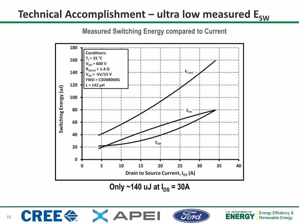
Only ~140 uJ at IDS = 30A
Measured Switching Energy compared to Current
Technical Accomplishment – ultra low measured ESW

16
• New project• No reviewer comments from last year
Response to Reviewer Comments

17
• None for public disclosure
Partnerships / Collaborations
18
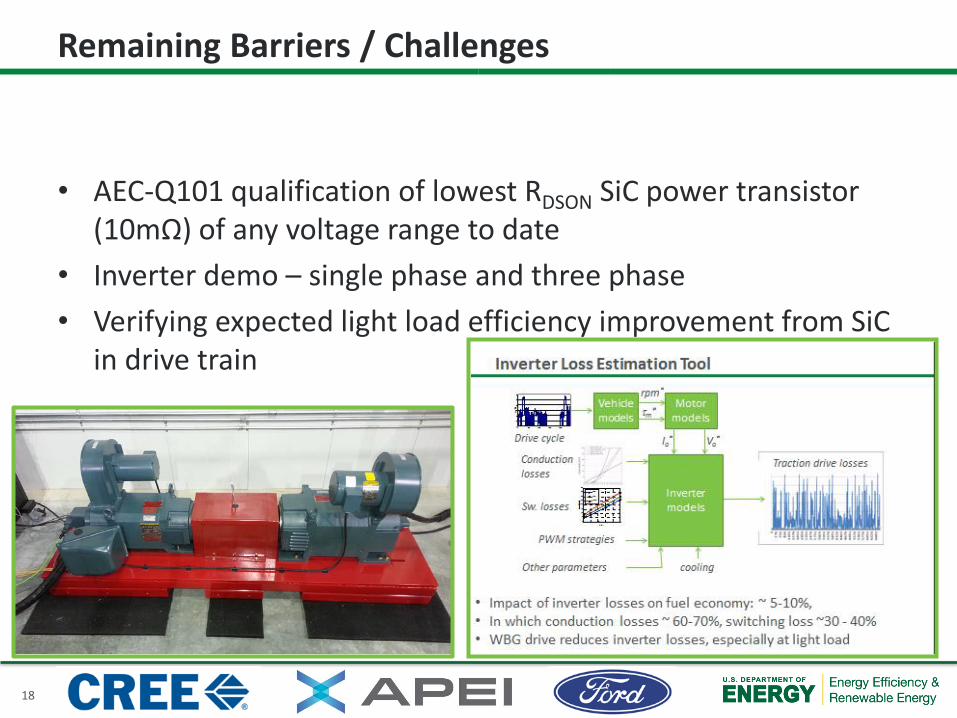
• AEC-Q101 qualification of lowest RDSON SiC power transistor (10mΩ) of any voltage range to date
• Inverter demo – single phase and three phase• Verifying expected light load efficiency improvement from SiC
in drive train
Remaining Barriers / Challenges

19
• In 2015:– Finish three lots of 900V, 10mΩ SiC MOSFETs and sample to
automotive OEM and Tier One suppliers– Build 900V, 200A, ½ bridge power module using new SiC MOSFET chips– Simulate the light load efficiency in the drive cycle using the new 900V
SiC MOSFET
• In 2016:– AEC-Q101 qualification of 900V, 10mΩ SiC MOSFETs at chip level– Build 70 ½ bridge power modules using new 900V SiC MOSFETs– Test MTTF and IOL of SiC MOSFET based power modules– Perform single phase and three phase inverter demo’s using new 900V
SiC MOSFET power modules
Future Work

20
• Cree will develop and optimize a 900V, 10 m-Ohm SiC MOSFET aimed at x-EV applications, based on specifications provided by Ford and other automotive Tier One suppliers.– 200-600 MOSFETs for external sampling from optimization lots.– 1,100 MOSFETs to APEI for module assembly from qual lots.– Cree will qualify the optimized SiC MOSFET chip according to AEC-Q101
(~1,500 MOSFETs)• APEI will construct 900V, 200A, ½ bridge power modules using the 900V
SiC MOSFET and benchmark against other technologies. Benchmark includes performance & reliability.– APEI will valuate the ½ bridge power module in an 88 kW peak power traction
drive inverter for x-EV.• Ford will provide technical input on system specifications, and evaluation
of new 900V SiC products developed.
Summary~3
kMOS
FETs
~ 70 m
odul
es