document title second line and third line · inductor is split to form a transformer •capable of...
TRANSCRIPT

POWER
CONSIDERATIONS
George Hadley ©2016, Images Property of their Respective Owners.
OUTLINE• Overview
• Voltage Regulation and DC/DC Converters
• Utility Power Considerations
• Battery Power Considerations
• Alternative Power Considerations
• Power Design Techniques
• Other Power Considerations
• Thermal Considerations

OVERVIEW• Why is power circuitry important?
• All electrical circuits need voltage/power/current
• All electrical components have strict V/I/P limits which must be adhered to
• Limited range of input voltage levels (utility power, battery voltage levels, etc.)
• Digital circuits often operate at one (or more) voltage levels (5V, 3.3V, 2.5V, 1.8V, 1.2V, 0.9V, etc.)
• Need to convert from input levels to appropriate output levels

VOLTAGE REGULATIONOverview
• Objective: accept a given input voltage and convert it to a
desired output voltage level
• Provide a “flat” voltage with minimal transients
• Common Regulator Approaches:
• Linear regulators and Low Dropout (LDO) regulators
• Switching regulators:
• Buck converters
• Boost converters
• Buck-Boost converters
• Flyback converters
• Other converters (Cuk, SEPIC, Push-Pull, etc.)

VOLTAGE REGULATIONRegulator Considerations
• Power/Voltage/Current: Maximum device ratings (W/V/A)
• Efficiency: % input power transferred to regulator output
• Ripple/Regulation: “Smoothness” of output voltage
(transient suppression)
• Isolation: Amount of isolation provided by device (V or kV)
• Dropout: Depending on desired
output current and output voltage
levels, a certain minimum input
voltage is required (example:
obtaining 5V@200mA might
require 5.5V Vin but 5V@4A
might require 7V or 8V Vin)

VOLTAGE REGULATIONRegulator Types: Linear Regulators
• Regulator acts as a resistive divider with a fixed input
voltage, dissipating excess input power as heat
• Common parts: LM7805, LM78xx and variants
• Pros: Extremely simple, cheap
• Cons: Generate significant
amounts of heat, require high
input voltages, require external
components (resistors, caps),
inefficient (typical efficiencies
of 30%~50%)
• Legacy design; largely obsolete

VOLTAGE REGULATIONRegulator Types: Low Dropout Regulators
• Similar operation to a linear regulator, but designed to
operate with a lower dropout than traditional linear regs.
• Used when a fixed voltage level is needed but current
demands are low (generally < 0.5A) (dropout < 3V)
• Pros: Simple, cheap,
improved efficiency,
lower dropout
• Cons: Significant power
lost as heat, require
external components,
inefficient at high
output currents

VOLTAGE REGULATIONRegulator Types: Switching Regulators
• Operate by switching power to load at high speeds
• High efficiencies: (80%+ efficiency typical)
• Recommended for most digital design applications
• Separated by energy storage mode: (forward vs. flyback)
• Forward: Energy delivered directly to load (no delay)
• Flyback: Energy stored in magnetic fields, later
delivered to load
• Separated by input/output (buck vs. boost vs. buck-boost)
• Buck: Higher Vin is “stepped down” to lower Vout
• Boost: Lower Vin is “boosted up” to higher Vout
• Buck-Boost: Topology offering buck and/or boost
operation

VOLTAGE REGULATIONSwitching Regulators: Buck Converters
• Switch an inductor on and off:
• Switch Closed: Inductor VL opposes input voltage Vin
• Switch Open: Inductor discharges stored energy
through load
• “Steps down” voltage (VO < VI)
• Pros: Efficient, no need for large
transformers, lower thermal
requirements
• Cons: Switching introduces
voltage ripple and EMI, current
can vary significantly over
switching cycle, complexity

VOLTAGE REGULATIONSwitching Regulators: Boost Converters
• Switch an inductor on and off:
• Switch Closed: Inductor charged via Vin
• Switch Open: Inductor discharges into capacitor/load
• Output voltage is “stepped up”
(VO > VI)
• Pros: Efficient, can power systems
from small power sources,
lower thermal requirements
• Cons: Switching introduces
voltage ripple and EMI,
complexity (ICs available)

VOLTAGE REGULATIONSwitching Regulators: Buck-Boost Converters
• Circuit operation:
• Switch Closed: Inductor charges, capacitor supplies
power to load
• Switch Open: Inductor supplies power to capacitor and
load
• Output voltage can be bucked or boosted
• Pros: Efficient, versatile, lower thermal requirements
• Cons: Switching introduces voltage ripple and EMI,
complexity, output
voltage polarity
reversed

VOLTAGE REGULATIONSwitching Regulators: Flyback Converters
• Similar in operation to a buck-boost converter, but
inductor is split to form a transformer
• Capable of doing AC/DC or DC/DC conversion
• Pros: Efficient, versatile, provides isolation
• Cons: Switching introduces voltage ripple and EMI,
complexity, requires
(potentially large
and heavy)
transformer

VOLTAGE REGULATIONSwitching Regulators: Other Topologies
• Other common switching converter topologies:
• Ćuk: Boost stage followed by buck stage with shared
capacitor for energy storage, continuous output current
• SEPIC: Similar to Buck-boost, but capable of shutdown
(0V output) and output is non-inverting
• Push-Pull: Smoother current, higher efficiencies, less
noise, higher cost (than Buck-boost)
• Charge Pump: Uses capacitors (rather than inductors)
as primary storage elements, low complexity, high
efficiency (up to 95%), load-dependent output voltage

VOLTAGE REGULATIONSwitching Regulators: COTS Converter Examples
• A few commercial off-the shelf (COTS) DC/DC converter
examples:
• Murata OKL-T-W12: 2.9-14Vin, 0.9-5Vout, 1A, 5W max,
$3.10/unit
• Rohm BP5275-50: 6-14Vin, 5Vout, 0.5A, 3W max, direct
replacement to TO-220 linear regulators, $5.63/unit

UTILITY POWER CONSIDERATIONSOverview
• Utility power: (sometimes known as “mains electricity”)
• AC power drawn from wall outlets
• US power grid standards:
• 110-127V @ 60Hz
• Max circuit current draw: 10A, 15A,
20A common (check your breaker
box!)
• Power grid characteristics and
plug types vary from
region to region

UTILITY POWER CONSIDERATIONSAnatomy of an AC Adapter
• Rectifier: A circuit which converts AC electricity to DC.
(This current is not necessary constant, but it flows in a
single direction)
• As of the mid-2000s, mostly switching supplies are used.
Two (deprecated) analog techniques:
• Half-Wave: Current flows during one-half of the phase
of the AC voltage waveform (deprecated)
• Full-Wave: Current flows during both phases of the AC
voltage waveform (deprecated)

UTILITY POWER CONSIDERATIONSAnatomy of an AC Adapter: Half-Wave Rectifier
• Half-wave rectifiers use specialized diodes rated for high
voltage, current, and power
• Pros: Extremely simple and (comparatively) cheap
• Cons: Half-wave designs introduce significant amounts of
voltage ripple at the output (more difficult to keep
capacitor charged between phases)

UTILITY POWER CONSIDERATIONSAnatomy of an AC Adapter: Full-Wave Rectifier
• Full-wave rectifiers typically use a group of 4 diodes
(sometimes known as a “diode bridge”)
• Pros: Simpler/cheaper than AC/DC converters (flyback),
less output voltage ripple than half-wave
• Cons: More expensive than half-wave, typically use
(large, heavy, expensive) transformers (flyback designs
can reduce transformer size)

UTILITY POWER CONSIDERATIONSFull-Wave Rectifier: Considerations
• Depending on your circuit demands a full-wave rectifier
may need to be followed by additional power filtering
and/or regulation circuitry
• Need to choose components rated for desired voltages
and currents
• The filter capacitor must be appropriately sized to achieve
a desired level of ripple voltage:

BATTERY POWER CONSIDERATIONSBattery Considerations
• Capacity(C): Charge storeable in battery (Ah or mAh)
• Current(I): Max charge/discharge rates often expressed in
terms of battery capacity (e.g. 1C, 5C, 0.65C, etc.) or A
• Voltage(V): Voltage provided by battery (V). Based on
battery chemistry. Varies with time, temperature
• Rechargeability: Some chemistries can be recharged
• Shelf Life: How well the battery retains its charge when
not in use
• Cycles (for rechargeables): How many charging cycles
the battery can sustain and retain its life
• Chemistry: Alkaline? Lithium? NiMH? Li-Ion? LiFePO4?
Other?

BATTERY POWER CONSIDERATIONSBattery Discharge Curves
• As a battery is used, its voltage decreases. The rate of
this decrease depends on temperature, rate of current
draw, and battery chemistry
• Voltage decrease is nonlinear, therefore simple
measurement of battery voltage may be a poor technique
for predicting remaining
battery life.
• Some chemistries
(such as Li-Ion) have
minimum voltages
needed for safe
operation
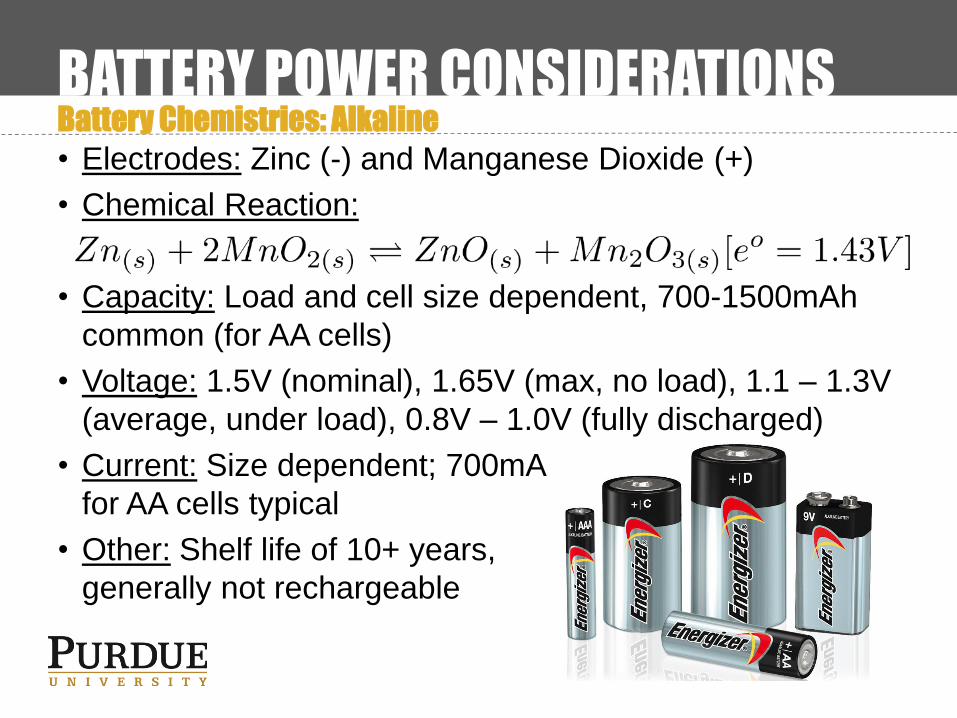
BATTERY POWER CONSIDERATIONSBattery Chemistries: Alkaline
• Electrodes: Zinc (-) and Manganese Dioxide (+)
• Chemical Reaction:
• Capacity: Load and cell size dependent, 700-1500mAh
common (for AA cells)
• Voltage: 1.5V (nominal), 1.65V (max, no load), 1.1 – 1.3V
(average, under load), 0.8V – 1.0V (fully discharged)
• Current: Size dependent; 700mA
for AA cells typical
• Other: Shelf life of 10+ years,
generally not rechargeable
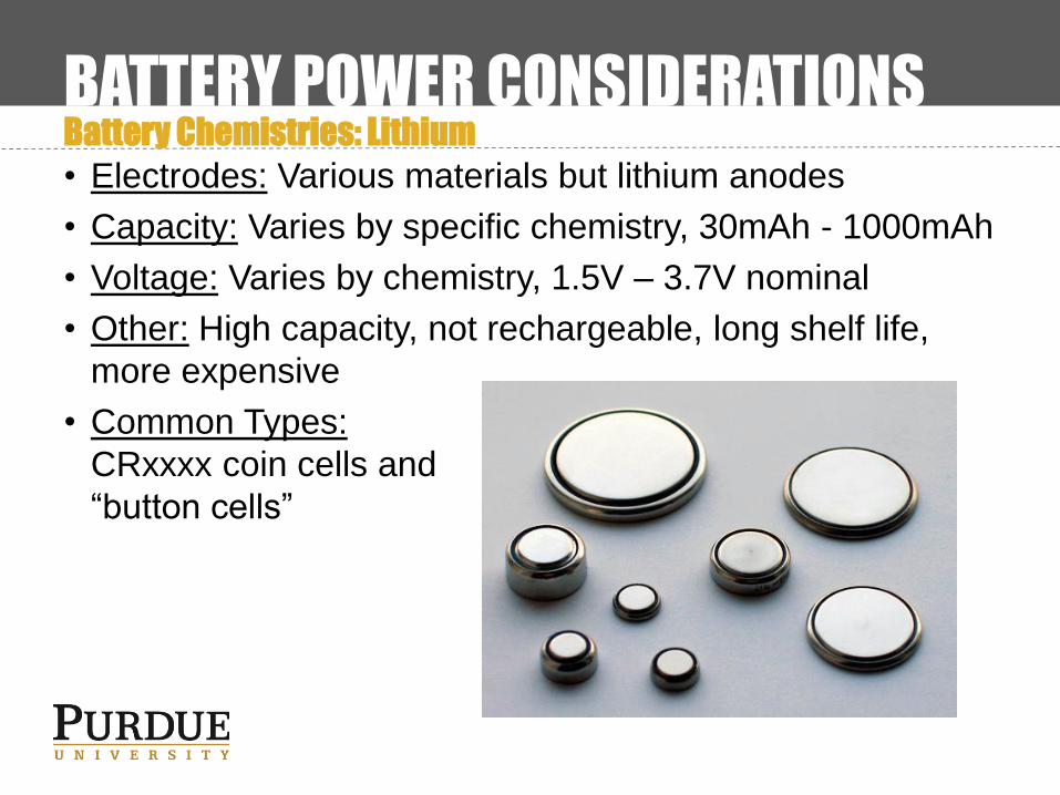
BATTERY POWER CONSIDERATIONSBattery Chemistries: Lithium
• Electrodes: Various materials but lithium anodes
• Capacity: Varies by specific chemistry, 30mAh - 1000mAh
• Voltage: Varies by chemistry, 1.5V – 3.7V nominal
• Other: High capacity, not rechargeable, long shelf life,
more expensive
• Common Types:
CRxxxx coin cells and
“button cells”
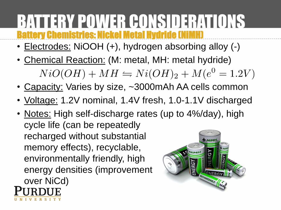
BATTERY POWER CONSIDERATIONSBattery Chemistries: Nickel Metal Hydride (NiMH)
• Electrodes: NiOOH (+), hydrogen absorbing alloy (-)
• Chemical Reaction: (M: metal, MH: metal hydride)
• Capacity: Varies by size, ~3000mAh AA cells common
• Voltage: 1.2V nominal, 1.4V fresh, 1.0-1.1V discharged
• Notes: High self-discharge rates (up to 4%/day), high
cycle life (can be repeatedly
recharged without substantial
memory effects), recyclable,
environmentally friendly, high
energy densities (improvement
over NiCd)
BATTERY POWER CONSIDERATIONSBattery Chemistries: Lithium Ion (Li-Ion)
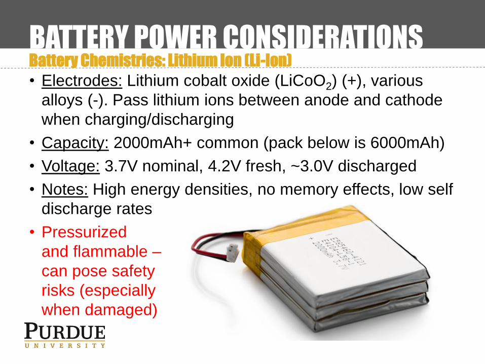
• Electrodes: Lithium cobalt oxide (LiCoO2) (+), various
alloys (-). Pass lithium ions between anode and cathode
when charging/discharging
• Capacity: 2000mAh+ common (pack below is 6000mAh)
• Voltage: 3.7V nominal, 4.2V fresh, ~3.0V discharged
• Notes: High energy densities, no memory effects, low self
discharge rates
• Pressurized
and flammable –
can pose safety
risks (especially
when damaged)

BATTERY POWER CONSIDERATIONSBattery Chemistries: Lithium Iron Phosphate (LiFePO4)
• Electrodes: Lithium Iron Phosphate (LiFePO4) (+), various
alloys (-). Variant of conventional Lithium Ion batteries
• Capacity: 2000mAh+ common (pack below is 6000mAh)
• Voltage: 3.2V nominal, 3.6V fresh, 2.0-2.5V discharged
• Notes: Lower energy density than Li-Ion, but improved
cycle life, longer lasting,
and considerably safer

BATTERY POWER CONSIDERATIONSBattery Chemistries: Other Battery Chemistries
• Zinc: Non-rechargeable chemistry. Worse performance
than alkaline but substantially cheaper
• Silver Oxide: Non-rechargeable chemistry. Safer and
more energy dense than lithium-ion tech. $$$$$$$
• Nickel Cadmium (NiCd): Rechargeable chemistry. Less
energy dense than NiMH but lower discharge rate
• Lead-Acid: Rechargeable chemistry. Most commonly
found in cars. Heavy but capable of supplying very
high surge currents. Cheap vs. comparable Li-Ion.
• Lithium-Sulfur Battery (Li-S): Potential emerging battery
technology, offers substantial energy density
improvements over conventional Li-Ion battery tech

BATTERY POWER CONSIDERATIONSBattery Charging Techniques
• Depending on battery chemistry, different charging
techniques are available to charge cells safely (cells can
be severely damaged from excessive voltage, current,
temperature, etc.):
• Trickle charging: Provide small amount of current to
maintain present battery state (often used for battery
backups)
• Fast charging: Utilize built-in safety features within
certain batteries to charge batteries more quickly
• CC/CV charging: 2-step charging process, in which a
battery is initially charged with a constant current. Once
a threshold is reached, the charger switches over to a
fixed voltage to complete charging

BATTERY POWER CONSIDERATIONSBattery Charging: Trickle Charging
• Simple trickle charger battery
backup example
• R1 must be sized properly
to allow for safe charging
current to be delivered to the
battery
• Power normally supplied via Vin
(regulated AC adapter or other source)
• When device is unplugged or power source for Vin
otherwise fails, D1 is reverse biased and D2 forward
biased, allowing the rechargeable battery to power the
load

BATTERY POWER CONSIDERATIONSCharging, Monitoring, and Power Management ICs (PMICs)
• Modern electronics systems can have complicated power
requirements, such as:
• Battery Charging: Needed for safely charging some
chemistries, especially lithium ion variants
• Power Source Selection: Multiple power sources (utility,
USB, battery backup, solar, etc.) may exist; need to
select the appropriate power source at a given time
• Power Sequencing: Depending on the application,
some systems/circuits/devices may need to be powered
on (or off) before others
• Battery Monitoring: Determine remaining battery life at a
given time (simple voltage measure often insufficient)
BATTERY POWER CONSIDERATIONSCharging, Monitoring, and Power Management ICs (PMICs)
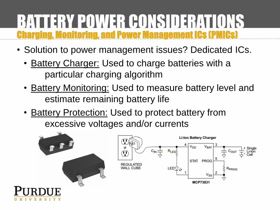
• Solution to power management issues? Dedicated ICs.
• Battery Charger: Used to charge batteries with a
particular charging algorithm
• Battery Monitoring: Used to measure battery level and
estimate remaining battery life
• Battery Protection: Used to protect battery from
excessive voltages and/or currents
AMBIENT POWER CONSIDERATIONSEnergy Harvesting
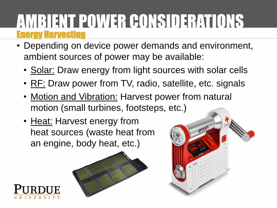
• Depending on device power demands and environment,
ambient sources of power may be available:
• Solar: Draw energy from light sources with solar cells
• RF: Draw power from TV, radio, satellite, etc. signals
• Motion and Vibration: Harvest power from natural
motion (small turbines, footsteps, etc.)
• Heat: Harvest energy from
heat sources (waste heat from
an engine, body heat, etc.)

POWER DESIGN TECHNIQUESSimple Programmable Shutdown

POWER DESIGN TECHNIQUESSimple Reverse Polarity Protection
• Q: What happens if somebody accidentally hooks up
power backwards?
• A (w/ no protection): Bzzzzzzt! *Smoke* Noooooooooo!
• A (w/ protection): Nothing.
• Other techniques include polarized or reversible
connectors (only one way to connect or connector
orientation doesn’t matter)

OTHER POWER CONSIDERATIONSWireless Transmission of Power
• Transfer power from one location to another without the
use of dedicated wires
• Popular for charging, situations where wires could twist or
get tangled, etc.
• Inductive coupling: A magnetic field
is induced by a transmitter and
received by a separate device
(RFID tags, etc.)
• Air core: Lossy, easy alignment
• Magnetic core: Similar to a
transformer; method used by
electric toothbrushes
THERMAL CONSIDERATIONSOverview
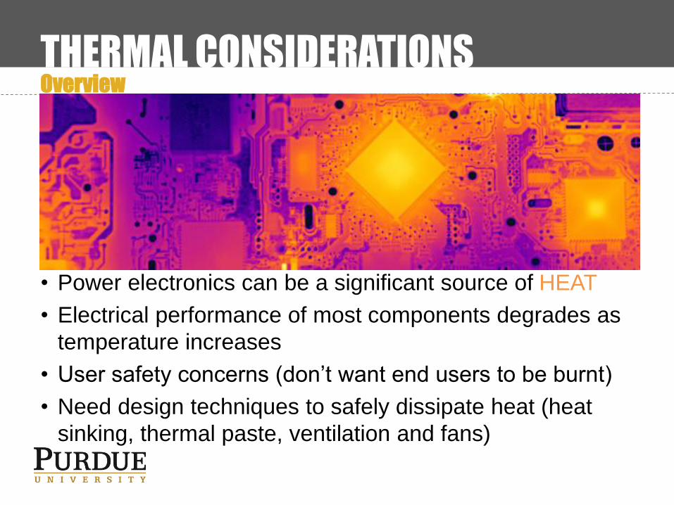
• Power electronics can be a significant source of HEAT
• Electrical performance of most components degrades as
temperature increases
• User safety concerns (don’t want end users to be burnt)
• Need design techniques to safely dissipate heat (heat
sinking, thermal paste, ventilation and fans)

THERMAL CONSIDERATIONSTemperature, Power, and Thermal Resistance
• Power: P = IV (measured in W)
• Temperature: Maximum temperature is generally a design
constraint (recall lecture 2)
• Thermal Resistance: A value given to heatsinks and
components, details a junction’s resistance to heat
flow (ºC/W) (↓Resistance → ↑Performance)

THERMAL CONSIDERATIONSHeat Sinks
• Heat Sinks: Passive devices used to transfer heat away
from a location and dissipate it into the environment
• Many varieties, depending on form factor, thermal
resistance, size, etc.
• Better thermal performance generally requires:
• Size: Larger heat sink = more thermal mass AND/OR
• Cost: More exotic and expensive materials

THERMAL CONSIDERATIONSThermal Paste
• While heat sinks are excellent conductors of heat, the
physical junction between it and a component of interest
is not
• Thermal Paste: Specialized compound designed to
provide adhesion and improve heat transfer at
component/heatsink junction
• Apply with care; some thermal pastes are conductive

THERMAL CONSIDERATIONSFans and Ventilation
• Heat sinks/thermal paste can effectively dissipate heat
from the immediate electrical junction, but sometimes this
heat must be further dissipated
• Adding ventilation for airflow may be an option for your
design (can allow outside contaminants and dust in)
• Fans can further increase airflow and heat dissipation in
your designs

THERMAL CONSIDERATIONSThermal Design Example
• Example: Suppose we have a linear voltage regulator
designed to regulate 6-10V input down to 5V while
passing up to 1A. For safety and performance purposes
this regulator should not exceed 122ºF (50ºC) (assume
room temperature operation of 25ºC)
• Questions: How much power can the regulator dissipate?
What temperature will the regulator reach without a
heatsink? What thermal resistance will be necessary to
meet the performance/safety spec.? What parts might we
use, and what might they cost (passive and forced air
cases)?

THERMAL CONSIDERATIONSThermal Design Example 2
• Dissipated Power:
Pmax = Vmax* Imax = 5V * 1A = ?????
• Estimated Temperature Change (no Heatsink):
Rθ(junction to case): 1.5ºC/W
Rθ(junction to air) : 65ºC/W
ΔT = Q*Rθ = 5W*(65ºC/W) = ?????
T = Tambient + ΔT = 25ºC + ?????
= ?????
• Thermal Resistance Needed to Meet Spec:
Rθ = ΔT/Q = 25ºC/5W ≈ ?????
Assuming thermal grease resistance of 0.1ºC/W (typical),
need heatsink with Rθ = (5 – 1.5 – 0.1)ºC/W = ?????

THERMAL CONSIDERATIONSThermal Design Example 3
• Dissipated Power:
Pmax = Vmax* Imax = 5V * 1A = 5W
• Estimated Temperature Change (no Heatsink):
Rθ(junction to case): 1.5ºC/W
Rθ(junction to air) : 65ºC/W
ΔT = Q*Rθ = 5W*(65ºC/W) = 325ºC
T = Tambient + ΔT = 25ºC + 325ºC
= 350ºC (662ºF)
• Thermal Resistance Needed to Meet Spec:
Rθ = ΔT/Q = 25ºC/5W ≈ 5ºC/W
Assuming thermal grease resistance of 0.1ºC/W (typical),
need heatsink with Rθ = (5 – 1.5 – 0.1)ºC/W = 3.4ºC/W

THERMAL CONSIDERATIONSThermal Design Example 4
• Heat sink parts meeting Rθ = 3.4ºC/W (without fan):
• Dimensions: 63.5mm (height) x 41.91mm (width)
• Minimum cost: $1.63/unit
• Reliability can be further improved using fans, ventilation,
and other techniques

Questions?