1. components - edgeedge.rit.edu/edge/p13623/public/workingdocuments/msd ii... · web viewfill the...
TRANSCRIPT

Conductive heat transfer lab #2
Table of Contents
1. COMPONENTS 1
A. MAIN UNIT 1B. COOLING UNIT 2C. POWER SUPPLY 2D. LIGHT BAR 2E. CONTROL BOX 2F. COMPUTER WITH LABVIEW (OPTIONAL) 2G. SAMPLES 2
2. SETUP 3
A. MAIN UNIT PREPARATION 3B. COOLANT PREPARATION 3C. ELECTRICAL PREPARATION 3
3. LAB PROCEDURE 4
4. EXAMPLE EXPERIMENTS 4
SAMPLE MATERIAL 4SAMPLE DIAMETER 4SAMPLE LENGTH 4SAMPLE SHAPE 4CONTACT PRESSURE 5CONTACT RESISTANCE 5COOLANT EFFECT 5POWER SUPPLY 5
5. STORAGE 5
1. Components
A. Main unit
Thermistor arms (6 + 4 extra) Transistor mounting bracket Flux transistors (2) Cold plate Cold water tubes and quick release (2) Pressure sensor
Heater Heater Assembly Communications cable
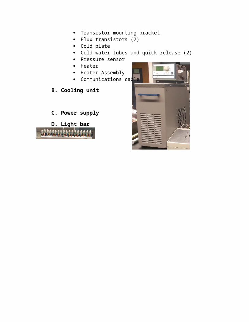
B. Cooling unit
C. Power supply
D. Light bar
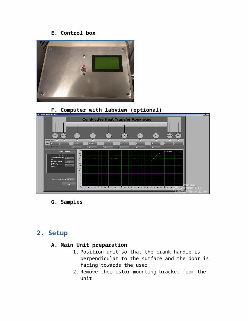
E. Control box
F. Computer with labview (optional)
G. Samples
2. Setup
A. Main Unit preparation 1. Position unit so that the crank handle is perpendicular to the
surface and the door is facing towards the user2. Remove thermistor mounting bracket from the unit 3. Position thermistor arms on the mounting bracket and tighten
down using an allen wrench. Note the position number. 4. Attach main cable to transistor units (red wire is power).
Thermistor cables are non-polar (order of wires does not matter). The pair of wires that says 1 should be closest to the heater, while the largest number should be closest to the cold plate.
5. Connect remaining wires (i.e. pressure sensor, cold top, cold bottom, heater). Note, all connections are non-polar
6. Insert thermistor mounting bracket into main unit7. Insert sample into unit and tighten hand crank. Be sure that the
sample is centered over the flux thermistor and that it is flush again the surface (to maximize heat transfer and minimize contact losses).
8. Position the mounting bracket such that there is a slight bend in the thermistor arms. Tighten down the mounting bracket
9. Close and secure door
B. Coolant preparation1. Fill the tower with fluid (water or ethylene glycol)2. Connect the supplied tubing to the cooling tower3. Insert the open (non-barbed) end into the quick release at the
base of the main unit. Repeat for the second tube
C. Electrical preparation1. Plug the main cable into the control panel2. Plug the light strip into the control panel into the “A type” USB
port3. Plug the power supply cables (red and black) into the control
panel4. Plug the control panel power supply into the “B type” USB port.
Plug the free end into the computer for labview use or the power supply unit for standalone use
5. Plug the power supply into a wall outlet or other power source
3. Lab Procedure A. Turn on coolant tower and set to desired temperature
B. Turn on power supply using the switch in the rearC. Set desired voltage (max 24 V) or current (max 2A). DO NOT YET
PRESS THE CENTER BUTTOND. Open supplied labview program
a. Check thermistors in use and set location on mountb. Enter voltage and current of the power supplyc. Set contact pressure to desired value by tightening or
loosening hand crankE. Be sure the LCD screen is on and the led lit F. Turn on power supply by pressing the center button on the unit and
by flipping the switch on the control panel to the on position G. If data taken manually: record temperature data every 3 minutes H. If data taken automatically: visually observe the temperature profile
in the labview interface and the calculated thermal conductivity I. Allow 40 to 60 minutes to reach steady state J. Note: when switching samples or when repeating tests, carefully
remove the sample by releasing pressure on the crank. Handle HOT sample with proper PPE (i.e. gloves) and immerse sample in room temperature water. Completely dry before reinserting into main unit
4. Example Experiments
Sample material1. Test the thermal conductivity of various materials 2. Maintain diameter and length of materials3. Aluminum and Copper samples provided (with comparable
dimensions)
Sample diameter1. Test the thermal conductivity of various diameter samples2. Maintain length and material type3. Copper samples provided
Sample length1. Test the thermal conductivity of various length samples2. Maintain diameter and material type3. Copper and aluminum samples provided
Sample shape1. Test the thermal conductivity of various shapes of samples
(cylinders vs. squares vs. rectangles) 2. Maintain material type and length 3. Samples NOT provided
Contact pressure1. Test the thermal conductivity of a single samples with various
pressure applied by the hand crank
Contact resistance1. Test the thermal conductivity of samples with various edge
finishes (polished vs. rough vs. partial contact due to edge or missing material)
2. Maintain material type, diameter and length 3. Samples provided
Coolant effect 1. Test the thermal conductivity of samples with coolant supplied
to one side vs. lack of coolant2. Done with one sample by running test with coolant tower
running and again without coolant tower running
Power supply1. Test the thermal conductivity of a single sample by changing
the power supplied to the unit (i.e. vary voltage or current)
5. Storage A. Unplug the main cable from the control panel, leaving internal
connections intactB. Unplug all connections to the power supply and control unit. Store in
main unitC. Store light bar inside main unitD. Store excess thermistors in main unitE. Remove connection to cooling tower by removing barbed ends F. Wrap main cable around door handle G. Compress crank to reduce area