p14361 technical paper reva.docx - rochester...
TRANSCRIPT

Project Number: P14361
THE JOURNEY: ENGINEERING APPLICATIONS LAB
Jennifer A. LeoneIndustrial Engineer
Henry AlmironMechanical Engineer
Angel HerreraElectrical Engineer
Dirk ThurMechanical Engineer
Larry HoffmanElectrical Engineer
Saleh ZeidanMechanical Engineer
ABSTRACT
The project goal was to design and create two laboratory modules that would be used in course MECE-301, Engineering Applications Laboratory. The modules would be used to teach the concepts of engineering analysis, practical experimentation, and introduce the students to new engineering principles. This would be provided by a set of advanced investigative scenarios that would be simulated by theoretical and/or computational methods, and then characterized experimentally. The goal was to provide the customer, a mechanical engineering professor at the Rochester Institute of Technology, Professor John Wellin, with two functional modules that could be tested throughout the duration of this course by students. The two modules the team chose to develop and design were a Railgun Module and a Static Thrust Testing Module.
Design considerations were outlined for the modules to make sure the selected projects met customer requirements and enhanced the student experience.The modules needed to be portable, safe, and robust while including multiple areas of analysis for students, and containing high levels of flexibility allowing for many engineering opportunities. All modules produced by this project needed to have the ability to be integrated with standard engineering software and data acquisition capabilities. This paper will outline the design and construction of the modules selected, the results and test data produced by the modules, and the experience that students will have when using the modules.
II. TECHNICAL INTRODUCTION
The start of the project was very abstract, the customer required the team to explore various module ideas without giving a clear direction as to what he was looking for. In order to find common ground with the customer, educational goals was developed to evaluate all module ideas. The main goal was to create modules to instruct engineering students in Engineering Applications Lab. The design goal was that the modules should be functional and self-sufficient. With these modules, students would be exposed to unfamiliar engineering principles. A budget constraint of $4,500 was given to the team to complete the project. Based on these goals, the team researched and bench marked projects that would fit the customer requirements. The team researched old projects and consulted the customer to find out which projects have been successful in the past. Fifteen module ideas were created and reviewed.
In order to filter and refine all ideas, a set of criteria was developed with the customer. The criteria consisted of a long list of requirements that each module needed to meet in order to be considered as a good project for Engineering Applications Lab. The first criteria that was evaluated was complexity, where the complexity of the concepts that each
P14361 – Page 1

module exhibited were evaluated based on customer feedback. The second criteria was safety, which was evaluated by having the team list possible hazards that could happen when using the module as well as evaluating how safe it was building the module. Another criteria was that the modules needed to be interesting and engaging to students, this was evaluated by seeing if the module was interesting to the team, if so then it would likely be interesting to the students as well. Cost of the module was considered and care was taken to stay inside the given budget. With customer approval, six of the module ideas remained, and were challenged against the criteria. Two modules were selected: a railgun and thrust module.
A rail gun is an energy conversion system that uses electrical energy and converts it into mechanical energy to launch a projectile. It consists of a pair of parallel conducting rails with an armature connecting them to complete the circuit and launch the projectile using electromagnetic motive force. The magnitude of the force vector can be determined by calculating the strength of the magnetic field through the Biot-Savart Law, and then finding the Lorentz force to determine the resultant force vector.
A propeller is a fan like machine whose rotation in a fluid creates a pressure difference between the forward and rear surfaces of the propeller's blades. This causes the fluid to accelerate behind the blade, which due to Newton's Third Law, the acceleration of the fluid causes the device that the propeller is attached to accelerate in the opposite direction. The force that produces this acceleration is called thrust.
III. DESIGN CONCEPTS
P14361 – Page 2

Each module had different technical challenges and tested different engineering skills. The railgun compares the velocity, capacitor bank capacity, and current determined in the analytical model, to the velocity measured in the experimental results. The time taken to charge up the capacitor bank varies slightly with the times that were determined via simulation. This could be due to variations and tolerances from parts used in the hardware implementation of this module. Overall these variations in time are not a large enough factor to cause any concern or changes to be made to the hardware used to charge up the capacitor bank.
The railgun module uses a set of two parallel rails and an armature to bridge the gap in between the two rails. This armature also doubles as the projectile that is accelerated and launched by electromotive force, which is produced when a high current is passed through the positive rail, armature, and lastly the negative rail. The power source that is used to produce this high of a current is a capacitor bank which consists of multiple axial can electrolytic capacitors. The current passing through the rails makes the railgun behave as an electromagnet, creating magnetic fields up the length of the rails up to the position of the armature. By the right hand rule the magnetic fields produced wrap around each conductor. The current traveling down each rail is opposite to the other, the magnetic field between the two rails is directed at right angles on the plane formed by the central axes of the rails and armature. The strength of the magnetic fields produced between the two rails can be roughly calculated using the Biot-Savart law (Eq#1). When the current running across the armature is combined with the magnetic fields between the rails this produces a Lorentz force (Eq#2) that accelerates the armature away from the power supply. A Lorentz force can also be experienced between the two rails pushing them apart, but since the rails are secured in place this does not cause any issues.
Biot-Savart Law (Semi-Infinite Current Carrying Wire) Eq#1
Lorentz Force Law Eq#2
The thrust module uses momentum theory to characterize the force produced by the propeller. This module is analyzed through equations and MATLAB software. The thrust module was required to produce a measurable quantity of thrust, without exceeding forty pounds of thrust or one hundred forty inch-pounds of torque, with these numbers being the limits of the load cell that the customer supplied. With theses limits in mind, benchmarking was then undertaken to find a similar system that produced enough thrust and that operated within the limits of our measuring device. This process brought the Hacker A-60-5S V2 brush-less DC motor to our attention, and we then modeled it using ECalc, a commercially available software program used for modeling the performance of r/c aircraft, with a variety of propellers to find a set up that would suite our needs. Once the motor and the propellers were selected, we then chose a speed controller with a maximum current that was twenty percent greater than the maximum current draw of the motor, following a standard rule of thumb that was conveyed to us by a vendor of r/c aircraft parts. The next step was powering our system, standard r/c aircraft batteries could not provide enough ampere-hours to sufficiently power our set-up through an hour long class, to rectify this we researched deep cycle marine batteries which could provide up to seventy-five ampere hours, enough to run the motor at full speed for forty-five minutes. Two batteries are run in series to create the necessary voltage needed to run the motor.
The Hacker A-60-5S V2 28 Pole Outrunner is an RC aircraft motor with a power range of twenty four hundred watts and spins at two hundred ninety five rotations per volt, which our simulations showed would provide a sufficient, impressive quantity of thrust without overloading the customer’s load cell. The speed controller that we chose for this project was Castle Creation’s Phoenix Edge 130, whose maximum current of one hundred thirty amps was deemed sufficient for our needs.
The force produced by the propeller can be found by the conservation of momentum which (assuming the fluid is inviscid, the fluid is incompressible, a uniform change in pressure along the propeller, and constant mass) is equation three, where P is pressure and A is Area . Using Bernoulli's equation (equation four, where ρ is density), you can relate pressure and velocity so that the equation becomes equation 6. Since only static thrust will be measured in this experiment, we can assume that Vo=0 and assuming that the exit velocity of the air is equal to the pitch speed (equation 7) of the propeller, thus the equation for static thrust will be equation 8.
Force due to change in momentum (simplified) Eq#3
P14361 – Page 3

Bernoulli's Equation Eq#4
Area of a Circle Eq#5
Expansion of equation 3 Eq#6
Pitch Velocity Eq#7
Equation for Static Thrust Eq#7IV. MODULE DESIGNThrust Module The thrust module design required two key aspects in order to obtain accurate data from the system. Safety
precautions were integrated into the design as per the costumers requirements. 1. Free flow of air
a. This was obtained by making the module self supporting and opening the top and bottom to allow air flow.
b. To prevent any large, foreign objects from being sucked or thrown into the air stream, 10 gage wire meshes were added to both ends.
Figure 3: Displays Grate on top of Module
P14361 – Page 4

2. Structural rigidity a. This were needed to support the load cell, motor, and propeller.b. To allow for a simple structure, most connecting point are 90 degree angle brackets with four screw
holes. The main issue with these brackets was that it is difficult to use all four holes since the inner two holes are too close for the insertion of the fourth screw. Since there will not be any thrust larger than 40 pounds it is safe to have the set up shown above.
To keep the students safe during the usage of this module, the structure has 0.2 inch thick clear polycarbonate sheets around all four sides. This allows students to view the system while it is running and keeping them out of harms way. In case of an emergency, there is an e-stop switch for the operator to use , which activates a safety relay switch
which cuts the power coming from the two Optima Blue Top marine deep cycle batteries. The switch runs on 12 volts provided by one of the batteries, and in cases where the battery is low on
charge and can’t provide 12 volts the switch would interpreter it as an off situation cutting the power to the speed controller.
To protect the student and the test setup from any short circuit, automotive battery terminal connectors were used to both connect the wire and shield it from any accidents. The connectors eliminated the need for anyone unsafely interacting with the battery terminal,s by providing a safe and easy way to disconnect the circuit.
Portability and FlexibilityAs part of the customer requirements, Professor John D. Wellin, required that this module should be portable
and usable in different locations. To do so we integrated four wheels rated at 300lbs each to be able to withstand all the structural and component weight of the module. The only aspect of this module that will not run without an outlet is the load cell, which requires 120V AC from a regular outlet. In order to keep the module portable, it needed to be within a set size to fit through doors. This limited height to 80 inches tall and 54 inches wide so we made the module 76 inches
tall and 36 inches wide to fit through R.I.T’s elevators and laboratory doors. To keep the students engaged in the module, the team designed it to be
easy for the student to change propellers and test their theoretical models. The students will be able to change propellers by simply using the access door at the front of the module. This module was design for a max propeller size of 27 inches, which depending on the drag coefficient would require a larger motor/speed controller or be limited at a lower rpm value.
To allow for easy disassembly/reassembly, This module was completely assembled using a set of standard Allen wrench, a screwdriver, and a 14mm wrench.
Build up Issues1. Both black ABS plastic sheets and one Polycarbonate sheet were cut larger than they needed to be.
● All parts were cut as needed with the assistance of the M.E machine shop advisers. 2. Screw count was less than expected
P14361 – Page 5

● Key structural parts such as wheels, mounting brackets and key joints got priority and all other parts were confirmed to be able to withstand more than 50lbs of load.
3. Access doors were not sized correctly ● To eliminate most gaps the wire mesh was bent while one of the structural bars was moved up. This
eliminated the issue while still ensuring the students safety in case of unexpected shrapnel flying from the setup.
4. Failure of speed controller● Took several weeks to order a new one and set back module in terms of inability to test it
Railgun ModuleThe railgun design required three key aspects in order for it to operate and obtain data. The railgun module
required that a majority of the system be enclosed in a container to prevent any harm to the users if any of the components were to be damaged. The enclosure also helped reduce the chance that the user may be electrocuted by live components or injured by any exploding components such as the capacitors.
1. Charging Systema. A variable charging system was accomplished with a Variac transformer which allowed the
user to control how much voltage from the wall socket goes into the system.b. A down-step transformer is connected right after the Variac transformer in order to bring
down and limit the voltage from the Variac to safer levels. c. Lastly the signal from the down-step transformer is passed through a bridge rectifier,
capacitor, and resistors in order to convert the AC signal to DC as well as smooth out the signal.
2. Capacitor Banka. This consists of eight capacitors that are arranged in a series connection to each other and is
used to store the electrical energy for the system. 3. Rails and Armature
a. Two copper rails are set up in parallel and connected to the capacitor bank. When a current is passed through the rails, this will produce magnetic fields around the copper rails.
b. The armature, which in this case is a car, is used to complete the connection between the two rails allowing a current to flow from the capacitor bank through the rails and armature.
Other important components that the customer stressed were for the of safety for the user. First, the enclosure that was chosen has six side locking latches that secure the lid of the enclosure, preventing the lid from being open when in operation. The enclosure also gives the customer the option to secure the lid further using screws on the corners or a pad lock. Another safety feature that was required by the customer, was a method for the capacitor bank and filtering capacitor to drain any stored voltage when not in use. This safety requirement was accomplished through the use of a bleeding circuit connected in parallel to both the capacitor bank and filtering capacitor. The bleeding circuit is comprised of resistors; the bleeding circuit for the capacitor bank is made up of just one high power fire resistant resistor. While the bleeding circuit for the filtering capacitor is made up of four high power fire resistant resistors, the difference in the amount of resistors is due to the fact that if a low resistance is used on the filtering capacitor this would have an effect on the charge times of the capacitor bank.
Portability and FlexibilityAs part of the customer requirements, Professor John D. Wellin, required this module should be portable and
usable in different locations. The module can be transported via a cart to move all components from one location to the next. Also, all hazardous components are housed in an enclosure for safety purposes.
Build up Issues1. Car did not originally move as quickly though the rails as expected
● Adjustments were made to the car to reduce the car’s weight, wheel friction and contact resistance.2. Incorrect down-step transformer ordered
P14361 – Page 6
● Values were recalculated in order to adjust the transformer to correct values and a replacement transformer was ordered.
3. Struggled with correct ratio for the car to correctly be launched● Car design was altered multiple times in order to find the correct ratio.
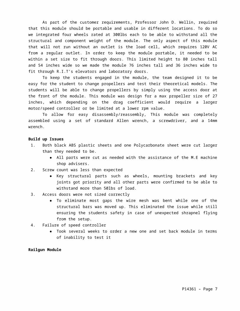
V. DATA COLLECTION AND TECHNICAL OUTCOMESDifferent parameters were collected in order to make sure that the railgun was functioning correctly and met
the customer requirements. Parameters included charge up times, discharge times, projectile acceleration, and projectile distance traveled. First, the customer wanted the system to reach full charge up in under a minute. After testing, this parameter was achieved. The charge up time was found to be under thirty seconds on average when charged to the rated voltage of the capacitors (10 Volts). Table 1 shows the charge up times at different levels of charge.
Input Voltage (Volts)
2.04 4.07 6.11 8.15 10.19
Time(sec) 3.54 8.03 12.21 17.27 22.32
Time(sec) 4.09 6.79 11.53 17.33 22.65
Time(sec) 3.53 7.05 11.63 16.61 22.73
Time(sec) 3.82 7.50 12.12 16.93 22.41
Time(sec) 3.90 7.08 11.93 16.74 22.67
Time(sec) 4.36 6.70 11.80 17.08 22.70
Average Time (sec)
3.87 7.19 11.87 16.99 22.58
Table 1: Capacitor Bank Charge-Up Times
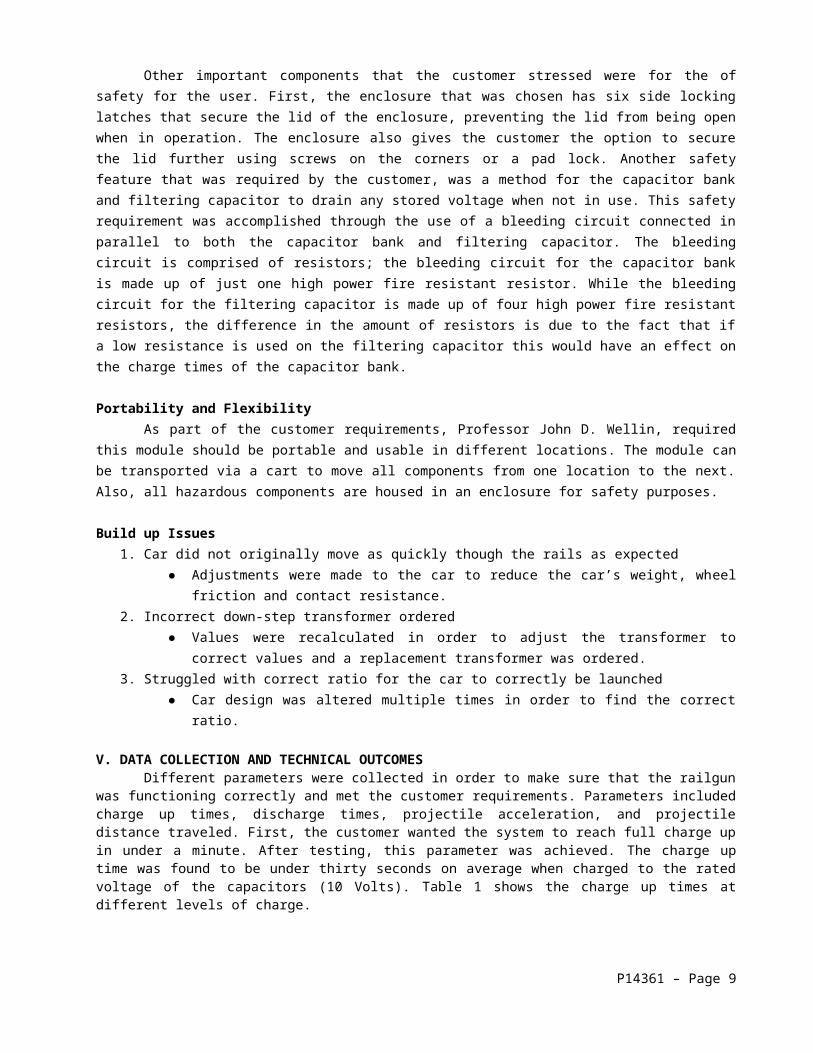
The second parameter that was required, was data on the discharge time of the capacitor bank into the bleeding circuit. The bleeding circuit was a safety system implemented to allow safe discharge of the capacitor bank. The customer requested that the system take no longer than a minute to discharge. This goal was accomplished with an average discharge time of a little under forty-two seconds with a total discharge from ten volts to five-hundred millivolts. Table 2 displays discharge times at different level of charge.
Input Voltage (volts)
2.04 4.07 6.11 8.15 10.19
Time (sec) 20.94 27.09 32.59 37.25 41.61
Time (sec) 18.22 27.38 33.05 36.94 41.47
Time (sec) 18.83 27.10 32.66 38.02 41.72
Time (sec) 17.77 27.76 32.37 38.14 41.54
Time (sec) 18.26 26.58 32.70 38.39 41.58
Time (sec) 18.73 26.65 33.04 38.28 42.52
Average Time (sec)
18.79 27.09 32.74 37.84 41.74
Table 2: Capacitor Bank Discharge Times
P14361 – Page 7

Thrust Module Due to issues encountered with the first test run with the original speed control, data was not able to be
formally collected. After acquiring a new speed controller (Castle Creations 130 ESC) on Dec 1st the following data was collected using the same propeller used at failure in the first test run. The test ran as follows:
1. Mount and Connect Load Cell2. Mount and Connect new Speed Controller3. Mount 27 in X 12 pitch propeller
a. Due to previous failures with this over-sized prop, we limited the signal sent to the speed controller to 1.1 ms (10% of the power)
b. Frame was then closed for safety4. Run Lab view code to record Load Cell Data5. Turn on the motor6. Sent low signal for initiation of testing 1.0 ms7. Worked up to 1.1ms in increments of 0.01 ms8. Data collected
Initial TestFigure 6, summarizes the amount of force that was measured during this test. Force can be measure in three
directions- X, Y, and Z. The Z axis is the most important: it shows 2 pounds of force was obtained during this test.
Figure 6: Load Cell Test
Load Cell Test
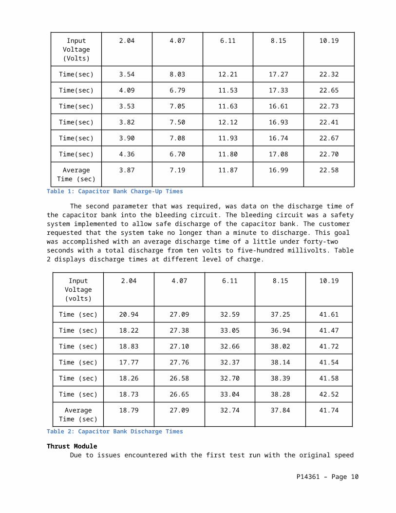
Using Force Gage acquired from Professor Hanzlik we applied 800g of upward force in the z direction in increments of 200g up to 2000g. The force gage is attached to the motor one inch from the center of the shaft, thus are expectations were for a force only in the Z axis. The lab view code used saves the data on a text file, using excel the data recorded is analyzed. Since the first few data point 0-220 is zeroing the load cell they are ignored. The load cell is zeroed with only the weight of the motor and mounting brackets. To analyze the data we averaged the force read by the load cell for the corresponding range.
Force Applied (g) Force Applied (lb)Time Range Average Force (lb) ΔF (lb)
800 1.763696 260-310 1.759501961 0.004194
1000 2.20462 345-360 2.2549 -0.05028
1200 2.645544 390-420 2.637819355 0.007725
1400 3.086468 440-460 3.08792381 -0.00146
1600 3.527392 480-500 3.524285714 0.003106
1800 3.968316 520-550 3.972980645 -0.00466
2000 4.40924 560-580 4.450257143 -0.04102
This data was collected to show that the load cell was calibrated correctly and will yield credible data with a max error of 0.04 lbs.
Propeller test Data
P14361 – Page 8
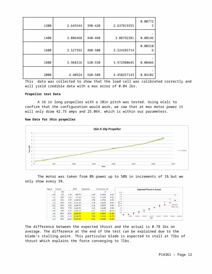
A 16 in long propeller with a 10in pitch was tested. Using eCalc to confirm that the configuration would work, we saw that at max motor power it will only draw 42.75 amps and 25.06V, which is within our parameters.
Raw Data for this propeller
The motor was taken from 0% power up to 50% in increments of 1% but we only show every 5%.
The difference between the expected thrust and the actual is 0.78 lbs on average. The difference at the end of the test can be explained due to the blade’s stalling point. This particular blade is expected to stall at 7lbs of thrust which explains the force converging to 7lbs.
STUDENT EXPERIENCE
The purpose of the Engineering Application Lab was for students get hands on experience with actual engineering projects. Students would test and compare analytical and experimental results that they obtain. Students would then make connection to the real world with hands-on experience.
For the railgun module, students have the opportunity to learn about technology and theories that are used in many modern objects, such as roller coasters and trains. This module will be outside the normal scope of any other labs that students may have performed. The concepts explored in the module will further reinforced electrical and mechanical engineering principles. The railgun works by following a process where the capacitor bank will first be charged to a desired voltage. This can be achieved by verifying that the charging switch is on, the bleeding circuit switch is off, and the fan is turned on. Once the switches are in the correct positions, the operator can turn on the variac and adjust the knob to achieve a desired voltage input. The voltage input from the variac is sent through a down-step transformer to keep the capacitors in the capacitor bank from being over charged to values that could damaged them or any of the other components in the system. The down-step transformer is designed to output at max input from the variac an output of 16 volts ac at 60 Hz. The output from the down-step transformer is then passed through a full bridge rectifier to convert the ac voltage signal to a dc voltage signal. Next, the rectified signal is passed through a resistor and capacitor to help clean up the voltage signal to the capacitor bank, which helps speed up the charge up process of the capacitor bank.
Once the capacitor bank is charged to a desired voltage value there are two options that the operator can take: one is to launch the projectile through the rails, the second is to discharge the capacitor bank into the bleeding resistor.
For the thrust module, students will use this module to test the effects of different propeller types, shapes and length for a desired thrust output. Variables that can be changed and tested are the angle of attack, motor speed, incoming air speed, propeller geometry, and weight/material of the system. Finally, this can help engage students’ interests in aviation and fluid dynamics.
P14361 – Page 9
The method of testing is very straightforward, the students will come to class with theoretical calculations predicting the thrust capabilities of a set of given propellers. The module is operated as follows: hit the emergency stop button to ensure the system has no power and attach a propeller to the motor securing it with the supplied mounting hardware. Next, connect the Optima 12V batteries in series; turn on the computer and run LabView and ensure communication between the load cell and DAQ is functioning. A function generator will control the ESC by connecting the positive banana clip to the orange signal wire and the negative banana clip to the brown signal wire on the ESC. The function generator parameters are as follows:
● Select “pulse” key● Set frequency to 50Hz● Set amplitude to 5Vrms● Set pulse width to 1ms
P14361 – Page 10

A pulse width of 1-2ms is essentially the throttle of the ESC, 1ms = 0% power and 2ms = 100% power. At this point disengage the estop and the system will start up, the ESC will beep 6 times, or the amount of battery cells it senses. Hit the “output” button on the function generator and the system is ready to be run. While Labview is recording data, the student will vary the speed of the motor. The students will export the data into excel and compare their recorded thrust to their expected thrust. After recording is complete the student will turn the throttle down to 0% and turn off the function generator, hit the estop to shut down the system and disconnect the batteries.VII. DISCUSSION
The railgun module was not successful in meeting all of the customer requirements that were established at the beginning of this project. First, the module was not fitted with a safety latch that would disengage the system when the top of the enclosure was opened. The issue was there was no solution that allowed the system to disengage the charging circuit to the capacitors and engage the bleeding circuit to allow the capacitor bank to discharge. Although this exact parameter could not be met, a manual switch was integrated into the system to allow the capacitors to discharge into the bleeding circuit. Another customer requirement not accomplished was the request to launch a car instead of a traditional projectile. Several attempts were made to try to achieve this goal but fell short due to improper sizing of the rails to the projectile. The projectile was changed back to the standard idea of trying to launch a normal rod or sphere instead of a car.
The end result of the building process fell short of our original end goal to have a fully functioning and user friendly lab module. The module was built to the point where the portability that the customer wanted was accomplished. All the electrical components were mounted and secured to the wood base that was placed inside the enclosure. The three wood bases are also secured to the enclosure itself with the use of cap screws and the mounting holes that are already part of the enclosure. The only component that did not go inside the enclosure was the variac. The variac did not fit inside the enclosure; this was a benefit in that it helped with moving the module from one location to another. Switches, necessary for functionality, were secured to the enclosure to allow the operator to control the railgun from the outside the enclosure when charging and discharging the capacitors. A DC powered fan was also placed inside of the enclosure to help prevent any overheating of the electrical components while in operation. A set of mounting brackets were made from the same red oak wood as the base pieces to help keep the rails secure and keep them a set distance apart during testing.
Overall the most critical components of the railgun module work with exception to the launch of the projectile across the rails. Connection design created that connects the variac to the module worked in the way it was designed. The charging circuit worked as expected and can charge the capacitor bank to full rated charge less than thirty seconds on average. The discharging circuit also worked as expected with the ability to discharge the capacitor bank on average in under forty-two seconds when charged to full rated charge. The cooling fan that was mounted in order to keep the electrical components from possibly overheating was not made operational. Lastly, the rails and projectile worked in the idea that it did allow the capacitor bank to discharge as expected but did not provide the acceleration on the projectile that was desired.
The failure of proper acceleration of the projectile was caused by multiple issues. These issues included improper rail geometry, rail spacing, projectile weights, projectile mass, initial velocities, magnetic field development, or stored voltage strength. One issue that was preventing the projectile from accelerating was the arc welding that occurred between the rails and projectile. Most welding happened during the first moment the projectile made contact with the rails; this was most likely due to the high contact resistance and high current discharge. These weld spots made test inconsistent because the projectile would not making sufficient contact over the weld spots. Preventing the projectile from accelerating as desired was the nature of the launch was a dynamic electrical phenomenon that occurred during a fraction of a second. This type of electrical phenomenon made it difficult to get accurate and predictable constant results over multiple trials.
CONCLUSIONS AND RECOMMENDATIONSIf this project were to be completed again, the team would have liked to have a better understanding of
expectations and guidelines prior to the beginning of the journey. The team did not really know where to start. It was not until the middle of MSDI that the team found the site that contained all of the old projects used in the Engineering Apps Lab. In addition to this resource, the team would have consulted current Engineering Apps Lab students what kind of projects they would be most interested in working on. The team had decided that if the modules were interesting to the team, it would be interesting and engaging to the students. Next time maybe this should not be assumed.
The team should have had a finalized design for each module by the end of week 15 in MSDI. The team spent the first three weeks of MSDII finishing the designs for the modules. This set the team behind where the team was supposed to be. Also, because the design was not fully completed our Bill of Materials was not complete. Screws, nuts and bolts were not added into the budget for the Thrust module until after the bill of module was accepted. The team had to buy additional parts that were not originally in the Bill of Materials. Thus, the team ended up going over budget
P14361 – Page 11
for the project. Money was allocated for additional parts needed but it was not enough to get the things we needed. Future teams should be advised to manage their budget and thoroughly make sure all parts are on the Bill of Materials before any parts are bought.
In order to complete module design and student experiences for both modules various improvements need to be implemented. For the thrust model, an over head fan should be integrated into the current design to add dynamic load testing to the propeller rather than just static loads. Another improvement would be to add a current reader to determine motor power use and accurately determine motor efficiency. Finally, a tachometer should be implemented to ensure RPM of the motor is what it should be.
For the railgun module, larger capacitors should be installed into the system in order to handle higher voltage values to allow higher current values to flow through the rails. Another improvement would be to use different rail dimensions to allow longer contact time for the projectile and lower resistance. Finally, a digital voltmeter should be that ca integrated into the outside of the enclosure to display capacitor bank charge.
The rail gun module did not work the way it had been planned. A car was envisioned to be launched out of a box on a track by the rail gun. A lot of “arcing” and “sparking” was observed; these were signs that the module was functioning. The most challenging aspect was to find the most efficient way to launch the car or even any projectile. As the week 15 deadline approached it was important to have a conversation with the customer to determine what would satisfy is requirements.
The conclusion of the project lead to individual and team lessons learned. First, if complete and finalized designs of the modules were made by the end of first phase of the project, there would have been more time to build, test and debug. Also, more time could have been dedicated to the logistics of the project. Deadlines and contingency plans are the heart of any project. If there was more detail dedicated to meet the deadlines, the project would have run more smoothly. In regards to a Bill of Materials, all materials, including screws, nuts and bolts, should have been priced from the beginning. Because these small but important items were not priced from the beginning, there was not enough money in the budget to get all materials required to finish the project. Finally, it was necessary to understand that this was a team project. Team members could not rely on one person to know all information about the project. If a team member could no longer participate in the project or was sick, the team was lost. Therefore, it is important that every team member needed to have a little knowledge of everything going on. Overall, the team learned how to work together, how to work with a customer and how to manage a project from start to finish.
ACKNOWLEDGMENTS The MSD Team would like to thank Professor Wellin, Professor Slack, Professor Venkataraman, Vanessa
Mitchell and the machine staff, Robert Kraynik and Jan Maneti for all their support, advice and time for the duration of this project. Finally, the team would like to thank Professor Hanzlik for all his guidance, advice and support to complete our deliverable.
P14361 – Page 12