doc 9830 - advanced surface movement guidance and control ... · icao regional director, middle...
TRANSCRIPT
International Civil Aviation Organization
Approved by the Secretary Generaland published under his authority
Advanced SurfaceMovement Guidanceand Control Systems(A-SMGCS) Manual
First Edition — 2004
Doc 9830AN/452

Published in separate English, Arabic, Chinese, French, Russian and Spanish editions by the International Civil Aviation Organization. All correspondence, except orders and subscriptions, should be addressed to the Secretary General. Orders should be sent to one of the following addresses, together with the appropriate remittance in U.S. dollars or in the currency of the country in which the order is placed. Customers are encouraged to use credit cards (MasterCard, Visa or American Express) to avoid delivery delays. Information on payment by credit card and by other methods is available in the Ordering Information Section of the Catalogue of ICAO Publications. International Civil Aviation Organization. Attention: Customer Services Unit, 999 University Street, Montréal, Quebec, Canada H3C 5H7 Telephone: +1 514-954-8022; Facsimile: +1 514-954-6769; Sitatex: YULCAYA; E-mail: [email protected]; World Wide Web: http://www.icao.int Botswana. Kags and Tsar Investments (PTY) Ltd., Private Bag 254/525, Gaborone Telephone: +267 390 4384/8; Facsimile: +267 395 0004; E-mail: [email protected] Cameroon. KnowHow, 1, Rue de la Chambre de Commerce-Bonanjo, B.P. 4676, Douala / Telephone: +237 343 98 42; Facsimile: +237 343 89 25;
E-mail: [email protected] China. Glory Master International Limited, Room 434B, Hongshen Trade Centre, 428 Dong Fang Road, Pudong, Shanghai 200120 Telephone: +86 137 0177 4638; Facsimile: +86 21 5888 1629; E-mail: [email protected] Egypt. ICAO Regional Director, Middle East Office, Egyptian Civil Aviation Complex, Cairo Airport Road, Heliopolis, Cairo 11776 Telephone: +20 2 267 4840; Facsimile: +20 2 267 4843; Sitatex: CAICAYA; E-mail: [email protected] Germany. UNO-Verlag GmbH, August-Bebel-Allee 6, 53175 Bonn / Telephone: +49 0 228-94 90 2-0; Facsimile: +49 0 228-94 90 2-22; E-mail: [email protected]; World Wide Web: http://www.uno-verlag.de India. Oxford Book and Stationery Co., 57, Medha Apartments, Mayur Vihar, Phase-1, New Delhi – 110 091 Telephone: +91 11 65659897; Facsimile: +91 11 22743532 India. Sterling Book House – SBH, 181, Dr. D. N. Road, Fort, Mumbai 400 001 Telephone: +91 22 2261 2521, 2265 9599; Facsimile: +91 22 2262 3551; E-mail: [email protected] India. The English Book Store, 17-L Connaught Circus, New Delhi 110001 Telephone: +91 11 2341-7936, 2341-7126; Facsimile: +91 11 2341-7731; E-mail: [email protected] Japan. Japan Civil Aviation Promotion Foundation, 15-12, 1-chome, Toranomon, Minato-Ku, Tokyo Telephone: +81 3 3503-2686; Facsimile: +81 3 3503-2689 Kenya. ICAO Regional Director, Eastern and Southern African Office, United Nations Accommodation, P.O. Box 46294, Nairobi Telephone: +254 20 7622 395; Facsimile: +254 20 7623 028; Sitatex: NBOCAYA; E-mail: [email protected] Mexico. Director Regional de la OACI, Oficina Norteamérica, Centroamérica y Caribe, Av. Presidente Masaryk No. 29, 3er Piso, Col. Chapultepec Morales, C.P. 11570, México D.F. / Teléfono: +52 55 52 50 32 11; Facsímile: +52 55 52 03 27 57; Correo-e: [email protected] Nigeria. Landover Company, P.O. Box 3165, Ikeja, Lagos Telephone: +234 1 4979780; Facsimile: +234 1 4979788; Sitatex: LOSLORK; E-mail: [email protected] Peru. Director Regional de la OACI, Oficina Sudamérica, Av. Víctor Andrés Belaúnde No. 147, San Isidro, Lima (Centro Empresarial Real, Vía
Principal No. 102, Edificio Real 4, Floor 4) Teléfono: +51 1 611 8686; Facsímile: +51 1 611 8689; Correo-e: [email protected] Russian Federation. Aviaizdat, 48, Ivan Franko Street, Moscow 121351 / Telephone: +7 095 417-0405; Facsimile: +7 095 417-0254 Senegal. Directeur régional de l’OACI, Bureau Afrique occidentale et centrale, Boîte postale 2356, Dakar Téléphone: +221 839 9393; Fax: +221 823 6926; Sitatex: DKRCAYA; Courriel: [email protected] Slovakia. Letové prevádzkové služby Slovenskej Republiky, Štátny podnik, 823 07 Bratislava 21 Telephone: +421 2 4857 1111; Facsimile: +421 2 4857 2105; E-mail: [email protected] South Africa. Avex Air Training (Pty) Ltd., Private Bag X102, Halfway House, 1685, Johannesburg Telephone: +27 11 315-0003/4; Facsimile: +27 11 805-3649; E-mail: [email protected] Spain. A.E.N.A. — Aeropuertos Españoles y Navegación Aérea, Calle Juan Ignacio Luca de Tena, 14, Planta Tercera, Despacho 3. 11, 28027 Madrid / Teléfono: +34 91 321-3148; Facsímile: +34 91 321-3157; Correo-e: [email protected] Switzerland. Adeco-Editions van Diermen, Attn: Mr. Martin Richard Van Diermen, Chemin du Lacuez 41, CH-1807 Blonay Telephone: +41 021 943 2673; Facsimile: +41 021 943 3605; E-mail: [email protected] Thailand. ICAO Regional Director, Asia and Pacific Office, P.O. Box 11, Samyaek Ladprao, Bangkok 10901 Telephone: +66 2 537 8189; Facsimile: +66 2 537 8199; Sitatex: BKKCAYA; E-mail: [email protected] United Kingdom. Airplan Flight Equipment Ltd. (AFE), 1a Ringway Trading Estate, Shadowmoss Road, Manchester M22 5LH Telephone: +44 161 499 0023; Facsimile: +44 161 499 0298; E-mail: [email protected]; World Wide Web: http://www.afeonline.com
3/08
Catalogue of ICAO Publications
Issued annually, the Catalogue lists all publications currently available. Supplements to the Catalogue announce new publications, amendments, supplements, etc. The Catalogue is accessible on the ICAO website at www.icao.int.

International Civil Aviation Organization
Approved by the Secretary Generaland published under his authority
Advanced SurfaceMovement Guidanceand Control Systems(A-SMGCS) Manual
First Edition — 2004
Doc 9830AN/452
AMENDMENTS
The issue of amendments is announced regularly in the ICAO Journal and in themonthly Supplement to the Catalogue of ICAO Publications and Audio-visualTraining Aids, which holders of this publication should consult. The space belowis provided to keep a record of such amendments.
RECORD OF AMENDMENTS AND CORRIGENDA
AMENDMENTS CORRIGENDA
No. Date Entered by No. Date Entered by
(ii)
(iii)
TABLE OF CONTENTS
Page Page
Foreword . . . . . . . . . . . . . . . . . . . . . . . . . . . . . . . . . . (v)
Acronyms, Abbreviations and Symbols . . . . . . . . . (vii)
Glossary . . . . . . . . . . . . . . . . . . . . . . . . . . . . . . . . . . . (ix)
Chapter 1. Introduction . . . . . . . . . . . . . . . . . . . . 1-1
1.1 Surface movement guidance and control system (SMGCS) operations . . . . . . 1-1
1.2 Goals for improving SMGCS . . . . . . . . . . . 1-21.3 A-SMGCS concept. . . . . . . . . . . . . . . . . . . . 1-2
Chapter 2. Operational Requirements . . . . . . . . 2-1
2.1 General . . . . . . . . . . . . . . . . . . . . . . . . . . . . . 2-12.2 System objectives and functions . . . . . . . . . 2-12.3 Division of responsibilities and functions . . 2-22.4 Implementation-related requirements. . . . . . 2-22.5 Basic functional requirements . . . . . . . . . . . 2-22.6 Supplementary requirements . . . . . . . . . . . . 2-52.7 System requirements . . . . . . . . . . . . . . . . . . 2-9
Chapter 3. Guidance on the Application of the Operational and Performance Requirements. . . . . . . . . . . . . . . . . . . . . . . . . . . . . . . 3-1
3.1 System objectives and functions . . . . . . . . . 3-13.2 Division of responsibilities
and functions . . . . . . . . . . . . . . . . . . . . . . . . 3-13.3 Implementation-related requirements. . . . . . 3-33.4 Basic functional requirements . . . . . . . . . . . 3-5
3.5 Supplementary requirements . . . . . . . . . . . . 3-143.6 System requirements . . . . . . . . . . . . . . . . . . 3-28
Chapter 4. Performance Requirements. . . . . . . . 4-1
4.1 System requirements . . . . . . . . . . . . . . . . . . 4-14.2 Surveillance requirements . . . . . . . . . . . . . . 4-24.3 Routing requirements . . . . . . . . . . . . . . . . . . 4-24.4 Guidance requirements. . . . . . . . . . . . . . . . . 4-24.5 Control requirements . . . . . . . . . . . . . . . . . . 4-2
Chapter 5. Implementation Issues . . . . . . . . . . . . 5-1
5.1 Introduction . . . . . . . . . . . . . . . . . . . . . . . . . 5-15.2 Capacity assessment. . . . . . . . . . . . . . . . . . . 5-15.3 Cost/benefit assessment . . . . . . . . . . . . . . . . 5-25.4 Generic methodology for assessing
capabilities of specific systems to meet A-SMGCS requirements . . . . . . . . . . . . . . . 5-9
5.5 Safety assessment. . . . . . . . . . . . . . . . . . . . . 5-105.6 Certification . . . . . . . . . . . . . . . . . . . . . . . . . 5-14
Appendix A. A-SMGCS Categorization . . . . . . . A-1
Appendix B. A-SMGCS Implementation Levels . . . . . . . . . . . . . . . . . . . . . . . . . . . . . . . . . . . . . B-1
Appendix C. Equipment Evolution for A-SMGCS . . . . . . . . . . . . . . . . . . . . . . . . . . . . . . . . . C-1
Appendix D. Target Level of Safety (TLS). . . . . D-1
Appendix E. A-SMGCS Research . . . . . . . . . . . . E-1

�������

(v)
FOREWORD
The systems described in the ICAO Manual of SurfaceMovement Guidance and Control Systems (SMGCS)(Doc 9476) are not always capable of providing thenecessary support to aircraft operations in order to maintainrequired capacity and safety levels, especially under lowvisibility conditions. An advanced surface movementguidance and control system (A-SMGCS), therefore, isexpected to provide adequate capacity and safety inrelation to specific weather conditions, traffic density andaerodrome layout by making use of modern technologiesand a high level of integration between the variousfunctionalities.
Due to the availability and development of new tech-nologies, including automation, it is possible to increaseaerodrome capacity in low visibility conditions and atcomplex and high-density aerodromes. In order to avoid atechnology-driven approach, generic operational require-ments were developed (see Chapter 2) which, irrespectiveof the technology used, provide guidelines for the analysisand development of local requirements.
The performance requirements contained in this manual(see Chapter 4) are intended to provide a possible solution
to safety- or capacity-related problems that have beenidentified up to this date. The A-SMGCS concept (seeChapter 1), however, is expected to continue to evolveas and when technology, systems and procedures aredeveloped.
The operational and performance requirements containedherein (see Chapters 3 and 4) are considered to benecessary for the selection, development and implementa-tion of an A-SMGCS at an aerodrome where the currentSMGCS needs to be upgraded, or for the introduction of anA-SMGCS at an aerodrome which currently has noSMGCS, but where the traffic density and/or aerodromelayout requires one.
This manual is intended as guidance to enable manufac-turers and operators, as well as certifying authorities, todevelop and introduce A-SMGCS depending on local cir-cumstances and taking into account global interoperabilityrequirements for international civil aviation operations.Applicable ICAO Standards and Recommended Practices(SARPs) should also be taken into consideration in thedevelopment and implementation of A-SMGCS.

�������

(vii)
ACRONYMS, ABBREVIATIONSAND SYMBOLS
Acronyms and Abbreviations
ADREP Accident/Incident Data Reporting (ICAO)
ADS-B Automatic dependent surveillance — broadcast
ARP Aerodrome reference pointARTS Automated radar terminal systemASDE Airport surface detection equipmentA-SMGCS Advanced surface movement guidance
and control system(s)ASR Aerodrome surveillance radarATC Air traffic controlATCO Air traffic controllerATIDS Aerodrome target identification
systemATM Air traffic managementATS Air traffic servicesAVOL Aerodrome visibility operational levelB BasicC ComplexCDB Capacity/demand balanceCFMU Central Flight Management UnitCWP Controller working positionDEFAMM Demonstration Facilities for
Aerodrome Movement Management (European Commission)
D-GNSS Differential global navigation satellite system
DLM Data link managerECAC European Civil Aviation ConferenceETA Estimated time of arrivalETD Estimated time of departureEUROCONTROL European Organisation for the Safety
of Air NavigationFAA Federal Aviation Administration
(U.S.)ft Footh HourH HeavyHMI Human-machine interfaceICAO International Civil Aviation
Organization
ILS Instrument landing systemkm Kilometrekt KnotL LightLAAS Local area augmentation systemLAN Local area networkLSS Loop sensor sub-systemm MetreM MediumNM Nautical mileNOTAM Notice to airmenNTSB National Transportation Safety Board
(U.S.)PD Probability of detectionPDA Probability of detection of an alertPDAS Pilot/driver assistance systemPFA Probability of false alertPFD Probability of false detectionPFID Probability of false identificationPID Probability of identificationRIRP Runway Incursion Reduction
Programme (FAA)RNP Required navigation performanceRVR Runway visual ranges Second S SimpleSARPs Standards and Recommended
PracticesSID Standard instrument departureSMGCS Surface movement guidance and
control system(s)SMR Surface movement radarSSDS Surface surveillance data serverSTAR Standard instrument arrivalTDMA Time division multiple accessTDOA Time difference of arrivalTLS Target level of safetyVDGS Visual docking guidance systemVFR Visual flight rulesVHF Very high frequencyWGS-84 World Geodetic System — 1984

Advanced Surface Movement Guidance and(viii) Control Systems (A-SMGCS) Manual
Symbols
° Degree= Equals> Greater than< Less than
– Minus% Per cent+ Plus± Plus or minus

(ix)
GLOSSARY
Note.— Some terms provided below are taken fromexisting ICAO documents, e.g. Annex 14.
Advanced surface movement guidance and control system(A-SMGCS). A system providing routing, guidance andsurveillance for the control of aircraft and vehicles inorder to maintain the declared surface movement rateunder all weather conditions within the aerodromevisibility operational level (AVOL) while maintainingthe required level of safety.
Aerodrome. A defined area on land or water (including anybuildings, installations and equipment) intended to beused either wholly or in part for the arrival, departureand surface movement of aircraft.
Aerodrome visibility operational level (AVOL). Theminimum visibility at or above which the declaredmovement rate can be sustained.
Airport authority. The entity responsible for the operationalmanagement of the airport.
Alert. An indication of an existing or pending situationduring aerodrome operations, or an indication of anabnormal A-SMGCS operation, that requires attentionand/or action.
Note.— The term alert covers warnings, cautions,advisories and alarms reflecting different levels of urgencyor equipment performance.
Apron. A defined area, on a land aerodrome, intended toaccommodate aircraft for purposes of loading orunloading passengers, mail or cargo, fuelling, parkingor maintenance.
Apron management service. A service provided to regulatethe activities and the movement of aircraft and vehicleson an apron.
A-SMGCS capacity. The maximum number of simul-taneous movements of aircraft and vehicles that thesystem can safely support with an acceptable delaycommensurate with the runway and taxiway capacity ata particular aerodrome.
Conflict. A situation where there is a risk for collisionbetween aircraft and/or vehicles.
Identification. The correlation of a known aircraft orvehicle call sign with the displayed target of thataircraft or vehicle on the display of the surveillancesystem.
Incursion. Any occurrence at an aerodrome involving theincorrect presence of an aircraft, vehicle or person onthe protected areas of a surface designated for thelanding, take-off, taxiing and parking of aircraft.
Manoeuvring area. That part of an aerodrome to be usedfor the take-off, landing and taxiing of aircraft,excluding aprons.
Movement area. That part of an aerodrome to be used forthe take-off, landing and taxiing of aircraft, consistingof the manoeuvring area and apron(s).
Note.— For A-SMGCS, the movement area does notinclude passive stands, empty stands and those areas of theapron(s) that are exclusively designated to vehicle move-ments.
Obstacle. All fixed (whether temporary or permanent) andmobile objects, or parts thereof, that are located on anarea intended for the surface movement of aircraft orthat extend above a defined surface intended to protectaircraft in flight.
Reversion time. Maximum time for reversion to manuallight control to be completed.
Road. An established surface route on the movement areameant for the exclusive use of vehicles.
Route. A track from a defined starting point to a definedend point on the movement area.
Runway incursion. Any occurrence at an aerodromeinvolving the incorrect presence of an aircraft, vehicleor person on the protected area of a surface designatedfor the landing and take-off of aircraft.

Advanced Surface Movement Guidance and(x) Control Systems (A-SMGCS) Manual
Stand. A designated area on an apron intended to be usedfor the parking of an aircraft. Stands can be classifiedas:
a) active stand — a stand that is occupied by a station-ary aircraft with engines operating, or on which anaircraft is moving, or that is being approached byan aircraft;
b) passive stand — a stand that is occupied by astationary aircraft with engines not operating; or
c) empty stand — a stand that is vacant and not beingapproached by an aircraft.
Surveillance. A function of the system which providesidentification and accurate position information onaircraft, vehicles and obstacles within the designatedarea.
System accuracy. A degree of conformance between theestimated or measured value and the true value.
Note.— For A-SMGCS, this includes the position andthe speed.
System availability. The ability of an A-SMGCS to performa required function at the initiation of the intendedoperation within an area covered by the A-SMGCS.
System continuity. The ability of an A-SMGCS to performits required function without non-scheduled inter-ruption during the intended operation within an areacovered by the A-SMGCS.
System integrity. System integrity relates to the trust whichcan be placed in the correctness of the informationprovided by an A-SMGCS. This includes the ability ofan A-SMGCS to provide timely and valid alerts to theuser(s) when the A-SMGCS must not be used for theintended operation.
System reliability. The ability of an A-SMGCS to performa required function under given conditions for a giventime interval.
Target. An aircraft, vehicle or obstacle that is displayed ona surveillance display.
Target level of safety (TLS). The probability of an accident(fatal or hull loss) during aircraft movement on theaerodrome.

1-1
Chapter 1
INTRODUCTION
1.1 SURFACE MOVEMENTGUIDANCE AND CONTROL SYSTEM
(SMGCS) OPERATIONS
1.1.1 Current SMGCS procedures are based primarilyon the principle “see and be seen” to maintain spacingbetween aircraft and/or vehicles on the aerodrome move-ment area. However, the number of accidents and incidentsduring surface movements, including runway incursions, isincreasing. Contributing factors include the increasingnumber of operations that take place in low visibility con-ditions,* the progressive increase in traffic, the complexityof aerodrome layouts, and the proliferation of capacity-enhancing techniques and procedures. Therefore, advancedcapabilities are needed to ensure spacing when visualmeans are not adequate and to maintain aerodrome capacityin all weather conditions.
1.1.2 Generally, operations at an aerodrome aredependent on air traffic controllers, pilots and vehicledrivers using visual observations to estimate the respectiverelative positions of aircraft and vehicles. Pilots and vehicledrivers rely on visual aids (lighting, markings and signage)to guide them along their assigned routes and to identifyintersections and holding positions. During periods of lowvisibility, controllers must rely on pilots’ reports andsurface movement radar to monitor spacing and to identifypotential conflicts. Under these conditions, pilots andvehicle drivers find that their ability to operate “see and beseen” is severely impaired. There are no prescribed separ-ation minima, and controllers, pilots and vehicle driversshare the responsibility that operations will not create acollision hazard.
1.1.3 All aerodromes have some form of SMGCS.Commonly used systems that have been installed in thepast are described in the Manual of Surface MovementGuidance and Control Systems (SMGCS) (Doc 9476). Intheir simplest form, SMGCS consist of painted guidelines
and signs, while in their most advanced and complex form,they employ switched taxiway centre lines and stop bars.All SMGCS provide guidance to aircraft from the landingrunway to the parking position on the apron and back to therunway used for take-off, as well as for other movementson the aerodrome surface such as from a maintenance areato an apron, or from an apron to an apron. In addition,SMGCS provide some guidance to vehicles. Normally,control of the activities and the movement of aircraft andvehicles rests with air traffic control (ATC) with respect tothe manoeuvring area. In the case of aprons, suchresponsibility sometimes rests with the apron management.Lastly, SMGCS may also provide guidance to, and controlor regulation of, personnel authorized to be on themovement area of an aerodrome.
1.1.4 For low visibility operations, plans of SMGCSprescribe the operational procedures that must be followedduring surface movements. Procedures vary from aero-drome to aerodrome depending on factors such as theregulations and policies of air traffic services (ATS), theorganizational responsibilities, and the aerodrome configu-ration and facilities.
1.1.5 Low visibility SMGCS procedures are put intoeffect when the runway visual range (RVR) decreases to apredetermined value (usually between 400 m and 600 m).Notifications are then issued to the aircraft operators,and checklists are used to implement the low visibilityprocedures.
1.1.6 In low visibility, designated low visibility taxiroutes may be used and depicted on aerodrome chartsavailable to pilots and vehicle drivers. Lighting systemssuch as stop bars and runway guard lights are used to assistATC in controlling access to active runways. Landingaircraft exit the runway at specific taxiways and follow thetaxi instructions from the ground controller. Access ofground vehicles is strictly controlled, and only essentialvehicles are permitted on the movement area.
1.1.7 At present, procedures permit aircraft to land inconditions down to zero visibility and to take off when the
* See Appendix A for the definition of visibilityconditions used in this manual.

Advanced Surface Movement Guidance and1-2 Control Systems (A-SMGCS) Manual
RVR is reduced to approximately 75 m. Although someStates use sophisticated taxiway guidance systems withstop bars to control movements, there are no ICAOprovisions for the operation of an SMGCS which canprovide for expedition and safety in all weather conditions.
1.2 GOALS FOR IMPROVING SMGCS
The following high-level goals provide a basis forconsidering what capabilities are required, and may beuseful in developing improvements for surface movementoperations:
a) controllers, pilots and vehicle drivers should beprovided with systems of the same level ofperformance;
b) controllers, pilots and vehicle drivers should haveclearly defined roles and responsibilities thateliminate procedural ambiguities which may lead tooperational errors and deviations;
c) improved means of providing situational awarenessshould be available to controllers, pilots and vehicledrivers, taking into consideration visibility con-ditions, traffic density and aerodrome layout;
d) improved means of surveillance should be in place;
e) delays in ground movements should be reduced,and growth in operations, including runwaycapacity, should be accommodated;
f) surface movement functions should be able toaccommodate all classes of aircraft and necessaryvehicles;
g) improved guidance and procedures should be inplace to allow:
1) safe surface operations on the aerodrome,taking into consideration visibility, trafficdensity and aerodrome layout; and
2) pilots and vehicle drivers to follow theirassigned routes in an unambiguous and reliableway;
h) improved aerodrome visual aids providing guidancefor surface movements should be an integratedcomponent of the system;
i) automation and Human Factors engineering shouldprovide the linkage between the surface and theterminal and between the terminal and the en-routeairspace to create seamless operations with reducedcontroller and pilot workload;
j) SMGCS improvements should be developed in amodular form to accommodate all aerodrome types;and
k) conflict prediction and/or detection, analysis, andresolution should be provided.
1.3 A-SMGCS CONCEPT
1.3.1 An A-SMGCS differs from an SMGCS in that itmay provide a full individual service over a much widerrange of weather conditions, traffic density and aerodromelayouts. A-SMGCS are to use common modules in allcircumstances. The modules to be used in any particularcircumstance are determined by the specific requirementsof each aerodrome.
1.3.2 The use of an A-SMGCS will lead to reallo-cation of responsibilities for various system functions. Lessreliance will need to be placed on the ability of the pilot orcontrol authority to provide visual surveillance. Somefunctions will use automation to provide routing, guidanceand control.
1.3.3 The main benefits to be accrued from theimplementation of an A-SMGCS will be associated with,but not limited to, low visibility surface operations.Significant improvements in aerodrome capacity can alsobe achieved under good visibility conditions.
1.3.4 The significant distinctions between the func-tions of a current SMGCS and an A-SMGCS are that thelatter should provide more precise guidance and control forall aircraft and vehicles on the movement area, and shouldalso be able to ensure spacing between all moving aircraftand vehicles, especially in conditions which preventspacing being maintained visually. It is therefore importantto recognize that, except where the total number of aircraftand vehicles permitted to operate on the movement area atany one time is kept very low, such tasks are beyond thecapability of a controller even if aided by conventionalsurface movement radar (SMR). Therefore, an A-SMGCSshould provide situation awareness not only to ATC butalso to those aircraft and vehicles that are liable to come inproximity to each other.

Chapter 1. Introduction 1-3
1.3.5 Complex traffic flows may require anA-SMGCS to function as a surface management system byproviding for the planning and management of all aircraftand authorized vehicles on the movement area whileinterfacing with the air traffic management (ATM) system.
1.3.6 An A-SMGCS addresses future increases insurface movement operations that would lead to increasedsurface congestion and system delays unless new tech-niques were made available to the air traffic controller toreduce workload. From the flight dispatch/apron manage-ment perspective, more sharing of information will beneeded to manage the availability of stands/parking areas,thereby reducing taxi delays to a minimum.
1.3.7 An A-SMGCS will reduce voice communica-tions, improve surface guidance aids and increase relianceon avionics in the cockpit to help guide the pilot to andfrom the runway. The ATC capability for surveillance byelectronic means will also improve. Automation will play agreater role to assist in monitoring the surface operations.
1.3.8 Communications will migrate into a mix ofvoice and data link capabilities, with automated datacommunications between system components providingsituation information between the users, including from theground to the cockpit. Voice communications will continueto be used where necessary.
1.3.9 Surface guidance will include improved visualaids for automated guidance and control along the assignedroute. However, for low visibility conditions, the pilot mayneed suitable avionics, such as a moving map, to monitorprogress and compliance with the assigned route. Theseavionics may also be used to display surface trafficinformation.
1.3.10 Improved ATC surveillance will provideaccurate information on the position and identity of allaircraft and vehicles operating on the movement area. Thiswill be used to enhance the automated functions associatedwith conformance monitoring and conflict alert. Also, thesurveillance information will be useful in refining thetraffic planning functions associated with predicting taxithroughput and arrival/departure times.
1.3.11 Automated functions will include the monitor-ing of conformance with taxi instructions and the detectionof potential conflicts and their resolution. Automationwill also be used to control ground visual aids based on
controller and surveillance inputs. Thus, the ground visualaids will be set up for the runway configuration in use, andrunway/taxiway intersections will be controlled based onprecise knowledge of the location and movement of aircraftand vehicles.
1.3.12 Surface traffic planning automation functionswill be integrated with approach/departure operations. Forarrivals, the sequence for each runway and stand assign-ment will be used to make accurate estimates of arrivaltimes at the stands. This information will improve aircrafthandling and turn-around time. For departures, engine startand push-back times can be coordinated and managed togain optimum departure sequencing, taking into account theplanned route. Also, aerodrome configuration changes willbe timed and implemented more efficiently, therebyminimizing any impact on the aerodrome utilization rate.
1.3.13 Development of complex systems and thediffering needs of users will require a modular developmentand introduction of various elements (some of which arealready in place). The expected evolutionary developmentof A-SMGCS and the varied needs of users will mean thatnot all aerodromes will introduce all provisions described inthis manual. Additionally, this manual can only outline stepsin the continuing enhancement of aerodrome operations.
1.3.14 The technical standards implied in this manualare recognized to be the most demanding for the mostcritical conditions in terms of visibility, traffic density andaerodrome layout. Implementation of facilities and pro-cedures to these levels will, therefore, not be appropriate atall aerodromes. Implementation of an A-SMGCS can onlytake place after an assessment of cost/benefit studies andconsideration of evolving user requirements. There will bea continuing need for dialogue between the suppliers ofservices, the manufacturers and the users so that theoperational requirements can be translated into technicalrequirements.
1.3.15 An A-SMGCS needs to be related to theoperational conditions under which it is intended that theaerodrome should operate. Failure to provide a systemappropriate to the demands placed on the aerodrome willlead to a reduced movement rate or may affect safety. It isimportant to recognize that complex systems are notrequired and are not economical at aerodromes wherevisibility, traffic density, aerodrome complexity and anycombination of these factors do not present a problem forthe ground movement of aircraft and vehicles.

2-1
Chapter 2
OPERATIONAL REQUIREMENTS
2.1 GENERAL
2.1.1 The operational requirements stated in thismanual refer to the most demanding conditions and are tobe applied depending upon visibility, traffic density,aerodrome layout and other local circumstances. Asmentioned earlier, the visibility conditions used throughoutthis manual are those described in Appendix A.
2.1.2 For a particular aerodrome, an A-SMGCS isintended to mean one integrated system providingadvanced surface movement guidance and control at thataerodrome. The accountability for the safety of operationsassociated with an A-SMGCS will ultimately lie with theservice provider, the airlines and the airport authority. Inthis manual, the term “responsibility” applies only to theperson or system and a designated role or function withinan A-SMGCS.
2.1.3 Airport authorities allocate their apron areas todifferent control authorities. In some cases, ATC hascomplete jurisdiction, and in others, there is some form ofapron or ramp control that exercises complete or partialjurisdiction on behalf of the airport authority. Whichevermethod of control is used, the level of service provided bythe A-SMGCS should be consistent from the runway to thestand and vice versa.
2.1.4 In order to resolve the problem of vehiclecontrol/segregation on a specific stand, the concept isintroduced whereby the role of that stand may change fromactive to passive and vice versa. Hence, the use of the term“movement area” in this manual excludes passive stands,empty stands and those areas of the apron(s) which areexclusively designated to vehicle movements.
2.1.5 An A-SMGCS, as described in this manual,requires the development of an integrated human-machineinterface (HMI) that will lead to a reduced workload forcontrollers, pilots and vehicle drivers by using computersand automation but retaining a manual control capability.
2.2 SYSTEM OBJECTIVESAND FUNCTIONS
2.2.1 In order to support optimized “gate-to-gate”operations, an A-SMGCS should be capable of assistingauthorized aircraft and vehicles to manoeuvre safely andefficiently on the movement area. An A-SMGCS shouldsupport the following primary functions:
a) surveillance;
b) routing;
c) guidance; and
d) control.
Note.— Communication is considered to be an integralpart of each of the primary functions.
2.2.2 In order to achieve the maximum benefits ateach level of A-SMGCS implementation, a supportingplanning function should be included.
2.2.3 An A-SMGCS should be capable of operating ata specified movement rate in visibility conditions down tothe aerodrome visibility operational level (AVOL). Whenvisibility conditions are reduced to below AVOL, anA-SMGCS should provide for a reduction of surface move-ments of aircraft and vehicles to a level acceptable for thenew situation.
2.2.4 The system should integrate movements toprovide complete situational information to all users, and toprovide conflict prediction and resolution for aircraft andvehicle movements.
2.2.5 A-SMGCS should be modular so that theappropriate level of service can be provided to differentaerodromes as well as to different areas of an aerodrome.

Advanced Surface Movement Guidance and2-2 Control Systems (A-SMGCS) Manual
2.3 DIVISION OF RESPONSIBILITIESAND FUNCTIONS
Although the responsibilities and functions may vary, theyshould be clearly defined for all users of the system. AnA-SMGCS should be designed so that the responsibilitiesand functions may be assigned to the following:
a) the automated system;
b) controllers;
c) pilots;
d) vehicle drivers;
e) marshallers;
f) emergency services;
g) airport authorities;
h) regulatory authorities; and
i) security services.
Note.— When using A-SMGCS, pilots remainresponsible for the safety and control of aircraft.
2.4 IMPLEMENTATION-RELATEDREQUIREMENTS
2.4.1 The design principle of an A-SMGCS shouldpermit modular enhancements. The A-SMGCS at eachaerodrome will comprise its own mix of modular compo-nents depending on the operational factors that arecategorized in Appendix A. For example, some modules ofan A-SMGCS will be required when one or more of thefollowing conditions exist:
a) visibility condition 2, 3 or 4; and/or
b) heavy traffic density; and/or
c) complex aerodrome layout.
2.4.2 The certification of an A-SMGCS shouldaddress the total system.
Note 1.— An A-SMGCS total system includes sub-systems, equipment and other components necessary for it
to perform its functions, as well as operational procedures,the identification of responsibilities, management functionsand system support facilities.
Note 2.— The addition of modules or the upgrading ofexisting modules will require an analysis to ensure that thecontinued validity of the original certification is notaffected. Where the continued validity of the originalcertification cannot be assured, a new certification of thecomplete system will be required.
2.5 BASIC FUNCTIONAL REQUIREMENTS
Note.— The interdependency of the primary A-SMGCSfunctions needs to be taken into account in addressing therequirements that follow.
2.5.1 Surveillance
2.5.1.1 The surveillance function of an A-SMGCSshould:
a) provide accurate position information on all move-ments within the movement area;
b) provide identification and labelling of authorizedmovements;
c) cope with moving and static aircraft and vehicleswithin the coverage area of the surveillancefunction;
d) be capable of updating data needed for the guidanceand control requirements both in time and positionalong the route; and
e) be unaffected by operationally significant effectssuch as adverse weather and topographical con-ditions.
2.5.1.2 The operational status of all surveillanceequipment should be monitored by the system, and alertsshould be provided as appropriate.
2.5.1.3 All control authorities concerned should beprovided with surveillance data in the required area of theaerodrome.
2.5.1.4 Within the required area of the aerodrome,surveillance should be provided up to an altitude so asto cover missed approaches and low-level helicopteroperations.
Chapter 2. Operational Requirements 2-3
2.5.1.5 Surveillance should be provided for aircrafton approach to each runway at such a distance that inboundaircraft can be integrated into an A-SMGCS operation sothat aerodrome movements, including aircraft departures oraircraft crossing active runways, can be managed.
2.5.1.6 A seamless transition should be providedbetween the surveillance for an A-SMGCS and the surveil-lance of traffic in the vicinity of an aerodrome.
2.5.1.7 The A-SMGCS should detect any incursioninto areas used for aircraft movement and the runwaystrips, and within any designated protected area as requiredby airport authorities. The surveillance system should alsocontinuously indicate the position of unauthorized aircraft,vehicles and obstacles in the above areas.
2.5.1.8 For aircraft and vehicles within the areas men-tioned in 2.5.1.7, the surveillance function of an A-SMGCSshould continuously provide information required to detectdeviations from the assigned route, with an update rate thatis sufficient to ensure an adequate response of the system.
2.5.2 Routing
2.5.2.1 Either manually or automatically, the routingfunction of an A-SMGCS should:
a) be able to designate a route for each aircraft orvehicle within the movement area;
b) allow for a change of destination at any time;
c) allow for a change of a route;
d) be capable of meeting the needs of dense traffic atcomplex aerodromes; and
e) not constrain the pilot’s choice of a runway exitfollowing the landing.
2.5.2.2 In a semi-automatic mode, the routing func-tion should also provide the control authority with advisoryinformation on designated routes.
Note.— In a semi-automatic mode, assignment of routesis carried out by the control authority.
2.5.2.3 In an automatic mode, the routing functionshould also:
a) assign routes; and
b) provide adequate information to enable manualintervention in the event of a failure or at thediscretion of the control authority.
2.5.2.4 When assigning routes, an A-SMGCS should:
a) minimize taxi distances in accordance with themost efficient operational configuration;
b) be interactive with the control function to minimizecrossing conflicts;
c) be responsive to operational changes (e.g. runwaychanges, routes closed for maintenance, and tem-porary hazards or obstacles);
d) use standardized terminology or symbology;
e) be capable of providing routes as and whenrequired by all authorized users; and
f) provide a means of validating routes.
2.5.3 Guidance
The guidance function of an A-SMGCS should:
a) provide guidance necessary for any authorizedmovement and be available for all possible routeselections;
b) provide clear indications to pilots and vehicledrivers to allow them to follow their assignedroutes;
c) enable all pilots and vehicle drivers to maintainsituational awareness of their positions on theassigned routes;
d) be capable of accepting a change of route at anytime;
e) be capable of indicating routes and areas that areeither restricted or not available for use;
f) allow monitoring of the operational status of allguidance aids; and
g) provide online monitoring with alerts where guid-ance aids are selectively switched in response torouting and control requirements.

Advanced Surface Movement Guidance and2-4 Control Systems (A-SMGCS) Manual
Note.— When visibility conditions permit a safe,orderly and expeditious flow of authorized movements, theguidance function will primarily be based on standardizedground visual aids. If expeditious flow is restricted due toreduced visibility, additional equipment or systems will berequired to supplement visual aids in order to maintainflow rates.
2.5.4 Control
2.5.4.1 The control function of an A-SMGCS should:
a) have a capacity sufficient for the maximumauthorized movement rate (dynamic capacity);
b) have a capacity sufficient for the aerodrome plan-ning of requested movements for a period of up toone hour (static capacity);
c) detect conflicts and provide resolutions;
d) be able to provide longitudinal spacing to predeter-mined values of:
1) speeds;
2) relative directions;
3) aircraft dimensions;
4) jet blast effects;
5) human and system response times; and
6) deceleration performances;
e) provide alerts for incursions onto runways andactivate protection devices (e.g. stop bars oralarms);
f) provide alerts for incursions onto taxiways andactivate protection devices (e.g. stop bars oralarms);
g) provide alerts for incursions into critical andsensitive areas established for radionavigation aids;
h) provide alerts for incursions into emergency areas;
i) be capable of incorporating computer-aidedmanagement tools;
j) keep controllers, pilots and vehicle drivers in thedecision loop;
k) control movements within a speed range so as tocover the operations in all required situations,taking into account the type of movement;
l) be capable of allowing operations to continue in allvisibility conditions down to the AVOL; and
m) be capable of allocating priorities to controlactivities.
2.5.4.2 The control function of an A-SMGCS shouldalso provide for:
a) sequencing of aircraft after landing, or of departingaircraft, to ensure minimum delay and maximumutilization of the available capacity of the aero-drome;
b) segregation of support and maintenance vehiclesfrom operational activities as necessary;
c) spacing between aerodrome movements accordingto the prescribed minima, taking into account:
1) wake turbulence;
2) jet blast and propeller/rotor wash;
3) aircraft dimensions; and
4) different locations and layouts (runway, taxi-way, apron or aircraft stand);
d) separation of movements from obstacles; and
e) separation with a prescribed minimum of all aircraftfrom an aircraft isolated for security reasons(Annex 14 to the Convention on International CivilAviation — Aerodromes, Volume I, Chapter 3).
2.5.4.3 The following short-term alerts should beprovided by the A-SMGCS within enough time to enablethe appropriate immediate action:
a) short-term conflict alert: whereby an alert istriggered when the predicted spacing will be belowpreset/predefined minima;
b) area penetration alert: whereby an alert is triggeredwhen a movement likely to enter a critical orrestricted area is detected;

Chapter 2. Operational Requirements 2-5
c) deviation alert: whereby an alert is triggered whenthe computed deviation will be more than thepreset/predefined maximum deviation;
d) runway incursion alert: whereby an alert is trig-gered when a movement likely to enter an activerunway (runway strip) is detected; and
e) taxiway (or an inactive runway being used as ataxiway) or apron incursion alert: whereby an alertis triggered when a movement likely to enter ataxiway or apron in use, which does not belong toits assigned route, is detected.
2.5.4.4 Distinctive medium-term alerts should beprovided well in advance to enable the appropriate remedialaction to be taken with respect to:
a) conflict prediction;
b) conflict detection; and
c) conflict resolution.
2.5.4.5 Once a conflict has been detected, anA-SMGCS should either automatically resolve the conflictor, on request from the controller, provide the most suitablesolution.
2.6 SUPPLEMENTARY REQUIREMENTS
2.6.1 Global risk factor
The introduction of an A-SMGCS should not result in anoverall level of risk in excess of the probability of one fatalaccident per 107 operations.
2.6.2 Aircraft types
An A-SMGCS should support operations involving allaircraft types and be capable of adaptation to cater forfuture aircraft types.
2.6.3 Vehicles
2.6.3.1 An A-SMGCS should be capable of beingused by appropriately equipped vehicles operating withinthe movement area.
2.6.3.2 Any authorized vehicle intended to be used onthe aerodrome in the vicinity of the manoeuvring areashould be equipped to inform an A-SMGCS of its position.
2.6.4 Speeds and orientation
The system should be capable of supporting operations ofaircraft and vehicles within the following parameters:
a) minimum and maximum speeds for aircraft on finalapproach, missed approach and runways;
b) minimum and maximum speeds for aircraft ontaxiways;
c) minimum and maximum speeds for vehicles; and
d) any heading.
2.6.5 Susceptibility
The system should not be affected by:
a) radio interference, including that produced bynavigation, telecommunications and radar facilities(including airborne equipment);
b) signal reflections and shadowing caused by aircraft,vehicles, buildings, snow banks or other raisedobstacles (fixed or temporary) in or near the aero-drome; and
c) meteorological conditions or any state of theaerodrome resulting from adverse weather in whichoperations would otherwise be possible.
2.6.6 Reference system
2.6.6.1 An A-SMGCS should be referenced to theWorld Geodetic System — 1984 (WGS-84).
2.6.6.2 A common reference point on aircraft andvehicles should be used in A-SMGCS.
2.6.7 Planning
2.6.7.1 In order to support the primary functions(surveillance, routing, guidance and control), the planningfacilities of an A-SMGCS should provide for:

Advanced Surface Movement Guidance and2-6 Control Systems (A-SMGCS) Manual
a) strategic planning which will indicate the predictedtraffic situation for chosen times in excess of20 minutes in advance;
b) pre-tactical planning which will indicate the pre-dicted traffic situation at a chosen time up to20 minutes in advance; and
c) tactical planning which will indicate the presenttraffic situation.
2.6.7.2 Planning facilities should include methods ofpredicting an aerodrome capacity and indication of start-uptimes for traffic to meet this capacity.
Note 1.— The capacity assessment is to be based onfactors such as weather conditions, serviceability of equip-ment, and closure of sections of the movement area.
Note 2.— Additional elements to be included in thecapacity assessment are the operational activity needs ofthe movement area, such as surface inspections, frictionmeasurement, and snow clearance.
Note 3.— The implementation of an A-SMGCS requiresthe designation of routes that ensure the safe and efficientmovement of aircraft and vehicles. The route issued for anymovement will be dependent on strategic, pre-tactical andtactical considerations that will be addressed within theoverall planning function.
2.6.8 Recording
2.6.8.1 Selected data on the communications controlactivity and display information should be recorded foraccident and incident investigation.
2.6.8.2 There should be a function to provide directreplay of recorded data within the operational system, aspart of the requirement for immediate checking of suspectequipment and initial incident investigation.
2.6.9 System failures
2.6.9.1 Equipment that shows control data should beboth fail-safe and fail-soft.
Note.— The term “fail-safe” in this context means thatsufficient redundancy is provided to carry data to thedisplay equipment to permit some components of the equip-ment to fail without any resultant loss of data displayed.
The term “fail-soft” means that the system is so designedthat, even if equipment fails to the extent that loss of somedata occurs, sufficient data remain on the display to enablethe controller to continue operations.
2.6.9.2 In case of a failure of an element of anA-SMGCS, the effect should be such that the status isalways in the “safe” condition.
2.6.9.3 All critical elements of the system should beprovided with timely audio and visual indications offailure.
2.6.9.4 An A-SMGCS should be self-restartable. Therecovery time should be a few seconds. The restart of anA-SMGCS should include the restoration of pertinentinformation on actual traffic and system performance.
2.6.10 Aerodrome considerations
An A-SMGCS should be capable of accommodating anychange in the layout of the aerodrome (runways, taxiwaysand aprons).
2.6.11 Pilot considerations
Pilots should be provided with the following:
a) information on location and direction at all times;
b) continuous guidance and control during:
1) the landing roll-out;
2) taxiing to the parking position and from theparking position to the runway-holding pos-ition;
3) lining up for an appointed take-off position; and
4) the take-off roll;
c) indication of the route to be followed, includingchanges in direction and indication of stops;
d) guidance in parking, docking and holding areas;
e) indication of spacing from preceding aircraft,including speed adjustments;

Chapter 2. Operational Requirements 2-7
f) indication of spacing from all aircraft, vehicles andobstacles in visibility condition 4;
g) indication of the required sequencing;
h) information to prevent the effects of jet blast andpropeller/rotor wash;
i) identification of areas to be avoided;
j) information to prevent collision with other aircraft,vehicles and known obstacles;
k) information on system failures affecting safety;
l) the location of active runways;
m) alert of incursions onto runways and taxiways; and
n) the extent of critical and sensitive areas.
Note.— Most of the foregoing requirements may besatisfied by using ground visual aids.
2.6.12 Vehicle driver considerations
2.6.12.1 Vehicle drivers should be provided with thefollowing:
a) information on location and direction at all times;
b) indication of the route to be followed;
c) guidance along the route being followed orguidance to remain within designated areas;
d) information, and control when and where appropri-ate, to prevent collision with aircraft, vehicles andknown obstacles; and
e) alert of incursions into unauthorized areas.
2.6.12.2 In addition to 2.6.12.1, the drivers ofemergency and operational vehicles should be providedwith:
a) the capability to locate the site of an emergencywithin the displayed range of the system; and
b) information on special priority routes.
Note.— Most of the foregoing requirements may besatisfied by using ground visual aids.
2.6.13 Apron management considerations
The following information should be available to the apronmanagement services:
a) information on the identity, position and progress ofaircraft, including aircraft under tow;
b) information on the identity, position and progress ofvehicles whose movements might conflict withaircraft movements;
c) information on the presence of obstacles or otherhazards;
d) information on the operational status of systemelements; and
e) information on facilities appropriate to the controlto be exercised.
2.6.14 Automation
2.6.14.1 Where automation is available, the auto-mated systems should demonstrate an acceptable level ofHMI efficiency.
2.6.14.2 The design of an A-SMGCS should make itpossible to make a distinction between the followingsystem elements and functions:
a) system assistance in the decision-making process;
b) system advice on the decisions taken; and
c) system decisions provided directly to the users.
2.6.14.3 Automated guidance should not be used bythe system if aircraft control, conflict detection and conflictalert resolution are not available.
2.6.14.4 If the system integrity degrades, the systemshould automatically alert all users and have the capabilityto transfer automated functions to the controllers in a safeand easy way.
2.6.14.5 Without automation, it may not be possibleto meet some operational requirements. Automation offunctions can be applied to various parts of an A-SMGCSsuch as:

Advanced Surface Movement Guidance and2-8 Control Systems (A-SMGCS) Manual
a) identification of aircraft and vehicles;
b) tracking and labelling of targets;
c) route assignment;
d) guidance and control;
e) runway incursion detection;
f) unauthorized intruder detection;
g) conflict prediction;
h) conflict detection;
i) conflict resolution;
j) alert indication;
k) indication of appropriate brightness setting forvisual aids; and
l) stand allocation.
Note.— Automation validation processes are expectedto encompass all environmental and failure conditionsincluding a reversion to manual control.
2.6.15 Human-machine interface (HMI)
2.6.15.1 The operation of an A-SMGCS should notinterfere with other ATC responsibilities.
2.6.15.2 The human-machine interface with anA-SMGCS should:
a) maintain a balance between the human and themachine functions;
b) permit the human to retain the power to makedecisions as to those functions for which the humanis responsible; and
c) provide for a balanced mix of visual, audio andtactile inputs and responses.
2.6.15.3 Input devices for the controllers should befunctionally simple — involving the controllers in a mini-mum number of input actions.
2.6.15.4 It should be possible to view displays andindicators in all ambient light levels typical of anaerodrome control tower environment.
2.6.15.5 Account should be taken of the ability of theflight crew and vehicle drivers to respond to the guidanceand control indications of the system.
2.6.15.6 The system should provide pilots and vehicledrivers with essential routing, guidance and control data ina standardized form that at all times is conspicuous,legible, comprehensible and credible. Guidance should beimplemented in such a way as to minimize the pilots’/vehicle drivers’ head down time, while maximizing the useof visual cues.
2.6.15.7 For control staff, the system should haveinterfaces that allow them to manage the routing, guidanceand control functions in a safe and efficient manner.
2.6.16 Interfaces
2.6.16.1 In order for all parties concerned to fullybenefit from an A-SMGCS, the system should be capableof interfacing with the following:
a) air traffic management (ATM), including:
1) arrival and departure management;
2) arrival and departure coordination;
3) optimized start-up sequence and times;
4) optimized push-back sequence and times; and
5) integrated initial flight plan processing system,central flow management unit, etc.;
b) aerodrome management systems;
c) existing and future ATS systems;
d) meteorological systems;
e) visual aids;
f) existing and future avionics;
g) aerodrome handling systems;
h) aircraft operators;
i) emergency authorities;
j) police/security authorities; and
k) other customers or users.

Chapter 2. Operational Requirements 2-9
2.6.16.2 The data interchange between systemsshould be made in a standardized format.
2.6.16.3 An A-SMGCS should enable controllers,pilots and vehicle drivers to interface and functionefficiently. These operators should also be capable ofinterfacing with other systems.
2.7 SYSTEM REQUIREMENTS
2.7.1 Accuracy
2.7.1.1 In specifying the positional accuracy par-ameters for an A-SMGCS, the requirements for the primaryfunctions and their interdependencies should be considered.
2.7.1.2 For the surveillance function, the allowableerror in the reported position should be consistent with therequirements set by the guidance and control functions.
2.7.1.3 For the guidance function, the allowablepositional errors should be similar for visual and electronictaxi guidance. However, in visibility conditions whereelectronic guidance is required in specifying the allowableerrors, taxiway widths and aircraft main gear wheel tracksshould be considered.
2.7.2 Update rate
Where appropriate, the update rate of an A-SMGCSmodule should be adequate for the required operationalperformance.
2.7.3 Integrity
2.7.3.1 The system design should preclude failuresthat result in erroneous data for operationally significanttime periods.
2.7.3.2 The system should have the ability to providecontinuous validation of data and timely alerts to the userwhen the system must not be used for the intended oper-ation. The validity of data should be assessed by the systemin accordance with the assigned priority given to these data.
2.7.3.3 Validation of operationally significant datashould be timely and consistent with human perceptionand/or response time.
2.7.4 Availability and continuity
2.7.4.1 The availability of an A-SMGCS should besufficient to support the safe, orderly and expeditious flowof traffic on the movement area of an aerodrome down toits AVOL.
2.7.4.2 An A-SMGCS should provide a continuousservice for all areas determined by the competent auth-orities. Any unscheduled break in operations should besufficiently short or rare so as not to affect the safety ofaircraft using the system.
2.7.4.3 Monitoring of the performance of anA-SMGCS should be provided so that operationallysignificant failures are detected and remedial action isinitiated to restore the service or provide a reduced level ofservice.
2.7.4.4 Automatic positive indication of the status ofthe system or any operationally significant failure should begiven to any aircraft, vehicle or control facility that may beaffected.
2.7.5 Reliability
2.7.5.1 An A-SMGCS should be designed with anappropriate level of redundancy and fault tolerance inaccordance with the safety requirements. A self-checkingsystem with failure alerts should be included in the systemdesign.
2.7.5.2 A failure of equipment should not cause:
a) a reduction in safety (fail-soft); and
b) the loss of basic functions.
2.7.5.3 The system should allow for a reversion toadequate back-up procedures if failures in excess of theoperationally significant period occur. Operationallysignificant failures in the system should be clearly indicatedto the control authority and any affected user.
3-1
Chapter 3
GUIDANCE ON THE APPLICATION OF THE OPERATIONALAND PERFORMANCE REQUIREMENTS
3.1 SYSTEM OBJECTIVES AND FUNCTIONS
The main objectives of an A-SMGCS (as stated in 2.2) maybe achieved by the following measures:
a) enhancing the surveillance function to ensure thatcontrollers receive all necessary information on allaircraft and vehicles on the movement area (includ-ing their identification) down to the AVOL;
b) enhancing the situation awareness of pilots,particularly in low visibility conditions — when the“see and be seen” principle is not applicable;
c) developing routing facilities in order to make fulluse of aerodrome capacity. This will require theprovision of a tactical planning tool;
d) providing clear indications of assigned routes topilots and vehicle drivers in the movement area sothat they can follow the assigned routes down to theAVOL; and
e) improving the control of runway and taxiingoperations by implementing incursion alerts andtools to predict, detect and resolve conflicts.
3.2 DIVISION OF RESPONSIBILITIESAND FUNCTIONS
3.2.1 General
3.2.1.1 The consideration of assigning responsibilitieswithin the operation of A-SMGCS will be a major factorin the overall design of such systems. The design ofA-SMGCS should not be constrained by existingallocations of responsibility. It should be recognized thatchanges may be required to make use of new technologyand operational concepts. New elements will be introducedas systems become more capable, and the correct operation
of certain functions will involve the responsibilities ofmanufacturers and producers of software. A thorough andongoing review of the present division of responsibility isrequired to see more clearly how new concepts will affectexisting arrangements.
3.2.1.2 The implementation of an A-SMGCS and itsassociated procedures enables the introduction of a highlevel of automation. This automation offers the possibilityof “system” management of safety-related tasks that arenormally performed by humans. Where there is a safetyrisk associated with the role and responsibility afforded tosystem functionality, a full risk assessment should becarried out.
3.2.1.3 It is a requirement for the design and use of anA-SMGCS that the responsibilities for the safe operation ofthe system be fully assigned. This assignment of responsi-bilities should be related to the operational conditions. Inlow visibility conditions, particular attention should be paidto this aspect of the design. Some of the principal areas ofresponsibility are:
a) the pilot of an aircraft is ultimately responsible forthe safety of the aircraft and will always remain incontrol of the aircraft;
b) the controller concerned will have the primaryresponsibility to operate and interpret theA-SMGCS;
c) a suitable A-SMGCS may be approved to auto-matically provide specific functions, such as identi-fication, guidance and conflict detection, tocontrollers, pilots and vehicle drivers; and
d) the pilot or vehicle driver will be responsible torespond to an A-SMGCS instruction or alert, unlessspecifically instructed otherwise by the controller.
3.2.1.4 Conflict detection is an example of aresponsibility within A-SMGCS which may be delegated insome circumstances to an automated system. The strategy

Advanced Surface Movement Guidance and3-2 Control Systems (A-SMGCS) Manual
for dealing with any conflict must be clearly defined underall circumstances. The proximity of two objects that isdeemed to constitute a conflict will be dependent on severalparameters (e.g. distance, speed and location).
3.2.2 Responsibilities
3.2.2.1 The area of responsibility for ATC on anaerodrome is normally the manoeuvring area. Services onthe aerodrome aprons are known as apron managementservices. Some States authorize a separate apron manage-ment unit, while in other States, ATC provides apronmanagement services.
3.2.2.2 Those responsible for operations on the aero-drome surface can be broadly categorized into five groups,each with distinct functions: aerodrome management, apronmanagement, ATC, pilots and vehicle drivers.
3.2.2.3 Personnel monitoring and operating theA-SMGCS equipment will have some responsibility forensuring that it functions correctly; however, human oper-ators can have no responsibility for automated functions forwhich they have no input.
3.2.2.4 Primary responsibility for the tactical oper-ation of an A-SMGCS will be vested in the controllerthrough the A-SMGCS, which may include:
a) guidance being provided by the system;
b) routing as assigned by the control authority;
c) conflict detection by the system and/or the control-ler; and
d) conflict resolution involving cooperation betweenthe system, controller, pilot and vehicle driver.
3.2.2.5 Vehicle drivers must comply with aerodromeregulations, the A-SMGCS, and ATC instructions. They arealways responsible for exercising due care and attention soas to avoid collisions between their vehicles and aircraftand other related hazards. Vehicle drivers should be pro-vided with the training necessary for them to understandtheir duties and to permit them to comply with aerodrome,A-SMGCS and ATC procedures.
3.2.2.6 Under the conditions envisaged for the oper-ation of an A-SMGCS, the system and its operators will berequired to accept a high level of responsibility for spacingbetween aircraft. There will still be options for the pilot to
maintain visual spacing under some circumstances, butthere will also be operational conditions when pilots willnot be able to see conflicting traffic and obstructions.
3.2.2.7 The nature of the conditions under which anA-SMGCS will operate requires that the pilot rely on theguidance and control that the system is providing. Thisguidance and control needs to extend from the runway tothe parking stand and vice versa. The areas used by servicevehicles which are not participating in the A-SMGCS willbe strictly segregated from areas used for aircraft move-ments. Additionally, with the highly complex workingenvironment and sophisticated HMI required for anA-SMGCS, training is necessary, with a licensing require-ment, to ensure the continued competence of operatingstaff. Responsibility for control needs to be allocated insuch a way that the same level of service is provided toaircraft and vehicles throughout the movement area.
3.2.2.8 ATC controls both aircraft and vehicles on themanoeuvring areas, giving aircraft priority. To do this, ATCmust use standardized radiotelephony communications withregard to phraseology, procedures and language. In lowervisibility conditions, when the responsibility for avoidanceof collisions on the ground becomes increasingly that of theATC unit, controllers may have to restrict the number ofaircraft and/or vehicle movements on the manoeuvringarea.
3.2.2.9 To enable ATC to carry out the above respon-sibilities, an A-SMGCS should be designed to at least assistin the prevention of:
a) incursions of aircraft and vehicles onto runwaysand taxiways in all visibility conditions; and
b) collisions between:
1) aircraft operating on the manoeuvring area inall visibility conditions;
2) aircraft and vehicles operating on the manoeu-vring area in all visibility conditions;
3) aircraft operating on the manoeuvring area andobstructions on that area in all visibility condi-tions;
4) vehicles operating on the manoeuvring area invisibility condition 4; and
5) vehicles operating on the manoeuvring areaand obstructions on that area in visibilitycondition 4.

Chapter 3. Guidance on the Application of theOperational and Performance Requirements 3-3
3.2.2.10 To enable the apron management unit tocarry out its responsibilities, an A-SMGCS should bedesigned to assist on the apron in the prevention of:
a) incursions of aircraft, vehicles and unauthorizedpersonnel onto designated areas and routes in allvisibility conditions; and
b) collisions in visibility conditions 3 and 4 between:
1) aircraft;
2) aircraft and vehicles;
3) aircraft and obstructions;
4) controlled vehicles; and
5) controlled vehicles and obstructions.
3.2.2.11 An interface should be provided between theapron management services and the aerodrome controlservices. The apron management services may be respon-sible for aircraft stand allocation and the dissemination ofmovement information to aircraft operators and couldachieve this by monitoring ATC frequencies and updatingbasic information on aircraft arrival, landing and take-offtimes.
3.2.2.12 The aerodrome management is responsiblefor the regular inspection of the manoeuvring area andaprons of the airport to ensure that all lighting, markingsand signage are kept serviceable and not obscured bycontaminants such as snow and ice. In addition, aerodromemanagement must designate standard taxi routes andvehicle operating lanes, control access to the movementarea, and train and motivate the aerodrome personnel.
3.3 IMPLEMENTATION-RELATEDREQUIREMENTS
3.3.1 Evolutionary implementation
3.3.1.1 It is not envisaged that the existence of oper-ational requirements for an A-SMGCS will immediatelyresult in a current SMGCS becoming obsolete. The strategythat underlies the requirements for an A-SMGCS assumesthat the development and implementation of the systemwill proceed at a pace that is primarily determined by
operational and economic considerations at each individualaerodrome. Appendix B lists criteria for determiningA-SMGCS implementation levels.
3.3.1.2 In general, an A-SMGCS should evolve fromthe installed SMGCS by progressive enhancements toexisting ground equipment to match the desired level ofoperations. The extent to which this should be done at anindividual aerodrome should be consistent with the levelsof traffic, the operating conditions and the configuration atthat aerodrome. Components can be added to an existingSMGCS when traffic requirements justify an expansion.The A-SMGCS solution for an aerodrome, therefore, willbe matched to its specific operational requirements andphysical characteristics. This evolutionary process is illus-trated in Appendix C.
3.3.2 Standardization and certification
3.3.2.1 A certification process, which is universallyapplied, is in place for aircraft, their operations and the avi-onics systems installed on board. It has agreed regulatoryobjectives and common procedures. This process is notnormally adopted for ATS systems. Ground system serviceproviders often specify the system taking into account cur-rent Standards and Recommended Practices (SARPs) butwill commission the system without independently agreedand harmonized safety objectives. With the implementationof an A-SMGCS, there is a need to adopt a certificationprocess that addresses the safety aspects of the system orservices in total. This approach is proposed for all new ATSsystems where there is an integration of new technology inthe airborne and ground elements, and where there isutilization of advanced automation techniques.
3.3.2.2 System certification would consider, and pro-vide proof of compliance with, safety requirements for eachfunctional domain within an A-SMGCS, and safety objec-tives for the procedures. Furthermore, safety and qualitymanagement infrastructures within the organizations pro-viding or using an A-SMGCS will need to demonstrateadequacy and be subject to continuous compliance moni-toring. The meeting of the certification criteria should leadto the granting of an approval for operational use of theA-SMGCS and for participating aircraft operators.
3.3.2.3 The use of the safety case methodology is onemeans of demonstrating the safety of an A-SMGCS. Thismethod provides reasoned arguments for the acceptabilityof the safety of the system. It also provides mechanismswhereby the safety of operations is continuously monitoredand, if necessary, improved.

Advanced Surface Movement Guidance and3-4 Control Systems (A-SMGCS) Manual
3.3.2.4 Certification should be a team effort. Theteam could comprise the A-SMGCS provider, the ATSprovider, the aerodrome authority, the participating aircraftoperators, and the certification authorities. Certificationauthorities should preferably be autonomous.
3.3.2.5 International standards and specificationsshould be used in the design of an A-SMGCS to enableinteroperability and open systems modularity. Interoper-ability should ensure that aircraft systems are compatiblewith any A-SMGCS throughout the world.
3.3.2.6 For a component to comply with interoper-ability requirements, industry standards are required. Thesestandards would define the minimum functional andperformance requirements. Substantiation of the interoper-ability requirements would also require a safety analysis ofthe functional performance of the component to determinethat no additional hazards are introduced. This would leadto the issuance of a type approval for that component andwould alleviate the need to re-certify all or a major part ofan A-SMGCS.
3.3.2.7 One aspect that should be considered whenmodifying a part of a certified system would be the impactof the modification on the operational use of the system.For example, before exchanging an A-SMGCS componentof one brand with another brand, it must be demonstratedthat the new component has the same functional character-istics as the original and that no safety requirements arecompromised.
3.3.3 Introduction of new technologies
3.3.3.1 In general, the introduction of new technologyfor A-SMGCS should conform with international stan-dards. The implementation of new technologies should besubject to the approval of the competent authority con-cerned.
3.3.3.2 For security and maintenance reasons, it ishighly desirable that all ground-based modules of anA-SMGCS are sited within the aerodrome boundary.
3.3.3.3 While it is beyond the scope of an operationalrequirement to specify technological solutions, there arecertain factors that affect the efficiency of operations thatneed to be taken into account when considering thetechnology to be used and the impact it may have onsystem performance. The following are the principalconsiderations:
a) surveillance:
1) at present, aerodrome control proceduresrequire visual confirmation to maintain safetylevels. In reduced visibility conditions thisability is impaired. Surveillance aids may beupgraded to provide target identification andclassification; and
2) surveillance tools may provide data for conflictprediction, detection and resolution;
b) communications:
1) radiotelephony should be retained for use at allaerodromes as the primary means to issuetactical instructions; and
2) data link may be used to supplement radio-telephony. It will be particularly useful toprovide clearances and routings that are notsubject to time critical transmission and that donot require instantaneous action. The format ofdata link messages and particularly the actualdisplay on the flight deck of such messagesrequire standardization. There is an importantdistinction between acknowledging the receiptof a data link message and actually understand-ing its meaning. To initiate free text data linkmessages from the flight deck may causedisproportionately high workloads; and
c) guidance and control:
1) current SMGCS already provide visual refer-ences as well as lighting, markings and signage.In the medium term, these references may befurther enhanced by switched centre line andstop bar lights. In conditions of great com-plexity or reduced visibility, additional facilitiesmay be required such as:
i) electronic displays;
ii) enhanced vision systems; and
iii) satellite-derived data; and
2) whatever precise guidance is provided to air-craft on taxiways and aprons — whether byenhanced lighting or by more sophisticatedtechniques — the command of the aircraftremains with the pilot.
Chapter 3. Guidance on the Application of theOperational and Performance Requirements 3-5
3.3.3.4 It will be important to achieve total inter-national standardization of:
a) visual guidance and aeronautical ground lightingsystems;
b) avionics display formats;
c) enhanced vision systems; and
d) non-visual guidance systems.
3.3.3.5 For wide-body aircraft, the large area ahead ofthe aircraft that is obscured by the cockpit cut-off results inincreased intensities being required to enable an adequatepattern of taxiway lights to be seen when the RVR is lessthan 75 m. Annex 14, Volume I, contains details of theminimum light intensities needed for different values ofAVOL.
3.3.3.6 An A-SMGCS may be used to increase thecapacity of high-density and/or complex aerodromes byimproving the planning and monitoring of ground move-ment in all weather conditions, or by improving guidance,while maintaining safety.
3.3.3.7 An A-SMGCS requires certain data that canonly be provided by external sources. Essentially this isanything that could have an operational impact on theA-SMGCS and may include, but is not exclusive to, thefollowing:
a) aerodrome information:
1) physical characteristics/layout;
2) runway(s) in use, including whether the runwayis exclusively used for landing or departingtraffic;
3) the demarcation of safety-significant areas, e.g.runway-holding positions, and navigational aidprotection areas;
4) runway and taxiway availability; and
5) work in progress;
b) meteorological information:
1) the prevailing and expected meteorologicalconditions at the aerodrome;
2) visibility/RVR, including, where applicable, onaprons and taxiways;
3) ceiling;
4) wind speed and direction;
5) atmospheric pressure; and
6) temperature and dewpoint; and
c) flight operational information:
1) AVOL;
2) wake turbulence; and
3) standard instrument departure (SID) and stan-dard instrument arrival (STAR) routes, includ-ing noise preferential routes.
3.3.3.8 Prior to updating an A-SMGCS, new datashould be validated. For example, new data should bechecked for inconsistency and unlikely variation fromprevious data, and for being out of tolerance.
3.3.3.9 All data provided by an A-SMGCS should begiven a date and time of issue and period of validity. TheA-SMGCS function or element, according to the data’s use,may determine the validity of the data. Informationreceived from a source external to the A-SMGCS that doesnot have a date, time and period of validity should beregarded as invalid. Old and invalid data should not beused.
3.4 BASIC FUNCTIONAL REQUIREMENTS
Note.— The functional operation of an A-SMGCS as awhole will consider the interdependency of the functions.Interdependency may change depending on the concept ofan A-SMGCS whether part or all of a functionality will beserved by another function.
3.4.1 Surveillance
General
3.4.1.1 Surveillance is an essential element of anySMGCS as well as any A-SMGCS. A combination ofvisual surveillance, SMR and radiotelephony is currently

Advanced Surface Movement Guidance and3-6 Control Systems (A-SMGCS) Manual
used by controllers to monitor movements. The monitoringof other aircraft and vehicles is also a significant functionperformed by pilots and vehicle drivers. As visibility isgradually reduced, the ability of controllers and pilotsto carry out visual surveillance becomes increasinglyimpaired. Problems for controllers become significantwhen the manoeuvring area cannot be adequately observedfrom the control tower. When the visibility falls below400 m, the ability of pilots and vehicle drivers to visuallyobserve becomes seriously impaired.
3.4.1.2 Improvement of the surveillance function toovercome the above-mentioned problems down to theAVOL is one of the key requirements of an A-SMGCS. Thesurveillance function therefore should provide identifi-cation of, and accurate positional information on, all move-ments on the movement area including the runway strip.
3.4.1.3 It is expected that more than one type ofsensor and a data fusion unit may be needed to meet therequirements specified below.
Reliability
3.4.1.4 In order to determine the reliability of theA-SMGCS surveillance function, the following parametersshould be considered in the specification of surveillanceequipment:
a) probability of detection (PD) — the probability thatan aircraft, vehicle or object is detected anddisplayed;
b) probability of false detection (PFD) — the prob-ability that anything other than an aircraft, vehicleor object is detected and displayed;
c) probability of identification (PID) — the probabil-ity that the correct identity of an aircraft, vehicle orobject is displayed; and
d) probability of false identification (PFID) — theprobability that the displayed identity of the air-craft, vehicle or object is not correct.
Coverage
3.4.1.5 The surveillance function should, dependingon the procedures in use, be capable of determining theposition and identification of aircraft and vehicles on themovement area, including obstacle-free zones and protectedareas.
3.4.1.6 The surveillance coverage area requirementsshould apply to operations in all visibility conditions.
3.4.1.7 The vertical surveillance coverage of anA-SMGCS should include all relevant non-surface oper-ations that take place at the aerodrome.
3.4.1.8 Information, including call sign and estimatedtime of arrival (ETA), on inbound aircraft should be pro-vided at least 5 minutes before touchdown or not less than10 NM from the aerodrome. The source of this informationmay not be part of the A-SMGCS. The information may beprovided by an external system.
Identification
3.4.1.9 The surveillance function should, within thespecified coverage areas, identify and provide the call signof each aircraft and vehicle and correlate the call sign withits position. The type of aircraft, including any variety,should be identified and verified. The position of obstaclesshould be appropriately marked.
Longitudinal accuracy
3.4.1.10 The accuracy requirement is based on theeffect of the surveillance accuracy on the ability to detectloss of required spacing and potential traffic conflicts or run-way incursions. Two scenarios were analysed: i) a runwayincursion where the aircraft crosses the runway-holdingposition; and ii) the loss of longitudinal spacing between twoaircraft. The runway incursion scenario was designed todetermine the warning time required of the surveillancesystem to the potential incursion, and to prevent the aircraftfrom proceeding onto the runway (see Figure 3-1). Thegeometry depicted is for airports where the runway-holdingposition is 75 m from the runway centre line.
3.4.1.11 Based on this scenario and a sensitivityanalysis of the effect of accuracy, it was determined that20 m would allow time (with some margin) for detection ofan incursion and stopping of the aircraft prior to enteringthe runway. This is based on the pilot being provided withconflict information directly.
3.4.1.12 In the case where an air traffic controllermust be alerted and then must issue instructions to the pilot,all accuracy values result in an excessive time delay, result-ing in an inability to prevent the aircraft from entering therunway. However, in general, a surveillance accuracy betterthan 20 m can result in significant improvements in system

Chapter 3. Guidance on the Application of theOperational and Performance Requirements 3-7
performance and allow more time for reaction to avoid aconflict. The longitudinal accuracy is recommended to be6 m.
Lateral accuracy
3.4.1.13 The required position accuracy is based onthe most demanding ICAO provisions to ensure a 3 mminimum clearance between an aircraft on the stand andany adjacent building, aircraft on another stand and otherobjects.
Data update rate and latency
3.4.1.14 An update rate of one second is required inorder to minimize time delays in detecting a loss ofrequired spacing and potential conflicts. With spacings andtime intervals being so short on the aerodrome, minimizingthis time is critical.
3.4.1.15 A limit on the variation in the update rate isnecessary primarily for Human Factors reasons. If theupdate rate varied significantly, the rate of movement oftargets would make it difficult to use judgement to deter-mine the motion of an aircraft or vehicle. Minimizing thisimproves the confidence of the air traffic controllers andpilots in the reliability of the information presented to them.Ten per cent is a suitable limitation on this variation.
3.4.1.16 For data latency, one second was chosen as areasonable upper value for the time between when thetarget position is determined and its use in detecting loss ofspacing or conflicts.
3.4.2 Routing
3.4.2.1 A routing function should enhance efficiency,particularly at complex aerodromes. In these situations, andwhen traffic density is heavy, some form of routing func-tion automation may be needed.
Coverage
3.4.2.2 The routing function should be capable ofproviding routing information for aircraft and vehicles onthe movement area and, where necessary, other areas usedby vehicles.
3.4.2.3 The routing function should provide anoptimized route for each participating aircraft and vehicle.It should consider the overall time for an aircraft or vehicleto complete the route in all visibility conditions.
3.4.2.4 The routing function should optimize thetraffic flow of aircraft and vehicle surface movements,including aircraft under tow, with respect to:
Figure 3-1. Runway incursion detection scenario
Surveillancedetection
Pilot initiatesbraking
Hold line 52 m
Runway
45 m75 m

Advanced Surface Movement Guidance and3-8 Control Systems (A-SMGCS) Manual
a) reducing delay — when planning a route, an effortshould be made to permit an aircraft to meet itsassigned take-off time or reach its allocated gate ontime;
b) potential conflict — the wing-tip to wing-tipspacing between certain types of aircraft on paralleltaxiways should be taken into account;
c) longitudinal spacing when visibility becomes afactor, including jet blast and propeller/rotor wash;
d) obstructed, unavailable or temporarily closed partsof the movement area; and
e) taxi speeds (to reduce braking and acceleration, andfuel burn).
3.4.2.5 The routing function should be able to handlepredefined or user-defined intermediate waypoints (e.g.routing through de-icing stations).
3.4.2.6 An alternative route should always be avail-able on request.
3.4.2.7 By human-initiated means, or as a result of aconflict, it should be possible to immediately cancel orchange an existing and used route. In the event that a routeis cancelled, a new route to continue should be provided.
Time to process route requests
3.4.2.8 To allow one second each for processing andtransmission means that the route would be available to thepilot within a few seconds (including controller responsetime), which should not have a significant impact on oper-ations provided that the route is determined prior to themovement.
3.4.2.9 The processing capacity is related to howmany routes can be requested at any one time. The assump-tion made is that the route request process is random; there-fore, over any one-second period, only a small number ofroutes could be requested. The largest demand will be whenthere is a large number of scheduled departures closelyspaced in time.
3.4.3 Guidance
General
3.4.3.1 When visibility conditions permit a safe,orderly and expeditious flow of authorized movements, the
guidance function will primarily be based on standardizedground visual aids including lighting, markings andsignage.
3.4.3.2 When visibility conditions are sufficient forthe pilot to taxi by visual guidance only, but the sole use ofvisual guidance restricts the expeditious flow of authorizedmovements, additional equipment or systems may beneeded to support the guidance function.
3.4.3.3 When visibility conditions are insufficient forthe pilot to taxi by visual guidance only, the aerodromeitself, as well as aircraft manoeuvring on the movementarea and authorized vehicles, should be appropriatelyequipped to comply with the guidance function (whenoperations in these visibility conditions are permitted).
3.4.3.4 Once a route has been assigned, the pilot orvehicle driver requires adequate information to follow thatroute. Guidance aids indicate where on the taxiway orapron the aircraft or vehicle can be manoeuvred safely.Switched centre line lights and/or addressable signs enableroutes to be uniquely designated.
Reliability
3.4.3.5 The following parameters should be con-sidered in the specification of guidance reliability require-ments:
a) probability of actuation — the probability that theguidance aid will respond correctly to the commandissued; and
b) probability of false actuation — the probability ofunsolicited actuation of a guidance aid.
Coverage
3.4.3.6 As a minimum, guidance should be providedon the airport movement area.
3.4.3.7 The following phases of a flight should beconsidered in the determination of the A-SMGCS coveragerequirement:
a) arrivals:
1) landing flare and landing roll begins;
2) high speed taxi;

Chapter 3. Guidance on the Application of theOperational and Performance Requirements 3-9
3) landing roll ends, taxi begins or, for a rapid exittaxiway, high speed taxi ends, taxi begins;
4) taxi ends, stand taxilane begins;
5) stand taxilane ends, stand begins (empty standbecomes active);
6) stand ends, docking begins; and
7) stand becomes passive;
b) departures:
1) passive stand becomes active;
2) stand taxilane begins (stand becomes empty);
3) stand taxilane ends, taxi begins;
4) taxi ends, take-off roll begins; and
5) take-off roll ends; and
c) apron movements, such as towing, and maintenanceactivities.
Visual aids
3.4.3.8 The current provisions for visual aids andother guidance provided are adequate for most aerodromeoperations. With the possible exception of visibilitycondition 4, additional equipment to that specified inAnnex 14 should not be required.
3.4.3.9 Annex 14 contains photometric requirementsfor taxi guidance visual aids, including taxiway centre linelighting, runway and taxiway intersection guard bars, andaddressable signs, that are intended to support A-SMGCSoperations.
Timing
3.4.3.10 When using a speed of 55 km/h (30 kt), thedistance covered by an aircraft or vehicle in two seconds isapproximately 30 m, which is the normal distance instraight sections between two centre line lights. Twoseconds should then be the maximum time to activate theon/off commands when guiding aircraft or vehicles withcentre line lights.
Failure of visual aids
3.4.3.11 In the event of a failure (other than a totalpower failure) of an automatic visual aids managementsystem, the A-SMGCS should be designed to switch on allthe runway guard bars at runway access points, and switchoff all taxiway centre line lights and intermediate stop bars.Manual selection and de-selection of the taxi guidancevisual aids should be provided.
Taxiway centre line light parameters
3.4.3.12 Fixed block lights — The length is estab-lished by longitudinal spacing between initial and finalblock stop bars. For safety reasons, one block should beleft free between aircraft, although this can limit taxiwaycapacity.
3.4.3.13 Variable block lights — The length of theblock in front of aircraft may vary according to the visualrange from two to six switched-on lights. Depending on thevisual range, up to three lights may be left switched offbetween the intersection of the cockpit cut-off area with thetaxiway centre line and the first switched-on centre linelight in order to facilitate pilot adaptation to be guided byswitchable centre line lights.
3.4.3.14 Visual aid instructions — Green lights infront mean “follow”. Where the pilot is instructed to followthe green lights, the absence of such lights indicates that thepilot or vehicle driver should stop. Red lights mean “stop”,and yellow or flashing lights mean “caution”.
Automatic light control by surveillance information
3.4.3.15 It should be feasible to design a guidancesystem to be controlled automatically, if only in part, by thesurveillance function in conjunction with the routingfunction. In this respect, taxiway lighting could be auto-matically switched on or off along the required route. Thisis a system development that might be explored in thefuture, as well as the automation of other visual aids.
Visual docking guidance system (VDGS)
3.4.3.16 Conventional visual markings for standentrance and parking are being replaced by more complexVDGSs. These systems are able to give precise informationon alignment and distance to go to flight crew members.Some are able to detect the type of aircraft. Such VDGSsshould be integrated within the A-SMGCS.

Advanced Surface Movement Guidance and3-10 Control Systems (A-SMGCS) Manual
3.4.4 Control
General
3.4.4.1 The design of any control system should takeinto account the requirements for safety and efficiency. Itshould also take into account the taxi performance andlimitations of all relevant aircraft and vehicles.
3.4.4.2 The control function should be able to handle:
a) deviations from assigned routes;
b) operational changes (e.g. runway changes, routesclosed for maintenance, and temporary hazards orobstacles);
c) priority routes designated to drivers of emergencyand operational vehicles; and
d) different groups of participants which can affectsafety, including aircraft, authorized airportvehicles, other airport vehicles (without any com-munication) and intruder vehicles.
Longitudinal spacing
3.4.4.3 Substantial research work will be required toestablish longitudinal separation requirements for groundmovement. In order to calculate the required longitudinalspacing, the following parameters should be considered:
a) the distance covered by the “following” aircraftduring the total time required for the pilot, control-ler and A-SMGCS to react;
b) the distance needed for an aircraft to stop;
c) the minimum distance to be maintained betweentwo aircraft at all times excluding jet blast effects;and
d) the sum of the aircraft length and the distancebehind the aircraft that must be kept clear to avoidjet blast effects.
Longitudinal spacing = a) + b) + c) + d) = St
Note.— The parameters are illustrated in Figure 3-2.
Figure 3-2. Longitudinal spacing parameters
St = Minimum longitudinal spacing
Aircraft B Aircraft A
La
Sp = Lj + La
LjSsSvSoDetectiondistance
Brakingdistance
Safetymargin
Jet blastmargin
Chapter 3. Guidance on the Application of theOperational and Performance Requirements 3-11
3.4.4.4 Other parameters that should be specified toenable longitudinal spacing to be calculated are:
a) Va — the initial speed of aircraft A (km/h);
b) Vb — the initial speed of aircraft B (km/h);
c) Aa — the deceleration of aircraft A (m/s2);
d) Ab — the deceleration of aircraft B (m/s2);
e) Pir — pilot reaction time (s);
f) Cor — controller reaction time (s);
g) Syr — system reaction time (s); and
h) Sar — safety reaction time (s).
Total time = e) + f) + g) + h) = Ts
Reliability
3.4.4.5 The following parameters should be con-sidered in the specification of control reliability require-ments:
a) probability of detection of an alert (PDA) situation— the number of correct alert reports generated bythe A-SMGCS over a given period of time,expressed as a percentage of the total number ofalert situations arising over the same period of time;and
b) probability of false alert (PFA) — the number offalse alert reports generated by the A-SMGCS overa given period of time, expressed as a percentage ofthe total number of alert reports recorded over thesame period of time.
3.4.5 Conflict alert
3.4.5.1 The objective of the control, guidance androuting functions should be to prevent a collision betweenaircraft, vehicles and other objects on the manoeuvringarea. This objective could extend to the prevention of aconflict.
3.4.5.2 The control function should be able to handle:
a) deviations from assigned routes;
b) events that impose operational changes (e.g.runway changes, routes closed for maintenance,and temporary hazards or obstacles);
c) priority routes designated to drivers ofemergency and operational vehicles; and
d) different groups of participants which can affectsafety, including aircraft, authorized airportvehicles, other airport vehicles (without anycommunication) and intruder vehicles.
3.4.5.3 The surveillance function contributes to situ-ational awareness and enables a continuous monitoring andassessment of conformance with the intended movements.
3.4.5.4 Once detected or predicted, a conflict shouldbe resolved according to its severity. There should besufficient time to resolve a predicted conflict through theplanning process. However, an actual conflict requiresimmediate action, which may be a system- or human-initiated resolution.
3.4.5.5 During visibility conditions when the “see andbe seen” principle can be applied without reducing aero-drome capacity, the longitudinal spacing facility of anA-SMGCS may only be required to detect possible conflicts.
3.4.5.6 An important aspect in conflict alert is the dif-ferentiation between detected and predicted conflicts (seeFigure 3-3). A detected conflict, which requires immediateaction to prevent a collision, should be given priority overa predicted conflict, which requires expeditious action toavoid the development of an imminent situation. The alert-ing system should indicate this difference by providing adifferent set of alerts to the users of the system.
3.4.5.7 Every aerodrome has site-specific parametersand situations to be addressed. The following list providessome of the possible conflict alert scenarios that should beboth predictable and detectable by the A-SMGCS:
a) runway conflicts:
1) aircraft arriving to, or departing aircraft on, aclosed runway;
2) arriving or departing aircraft with traffic on therunway (including aircraft beyond the runway-holding positions);
3) arriving or departing aircraft with movingtraffic to or on a converging or intersectingrunway;

Advanced Surface Movement Guidance and3-12 Control Systems (A-SMGCS) Manual
Figure 3-3. Conflict alert
Planning
Plannedsituation
Unexpectedevent
Real-time data
STARTSituation
monitoring
Real-timeevaluation
Conflictcriteria
Conflictdetected?
NO Forecastevaluation
YESALARM
NOConflictpredicted?
YESWARNING
Conflict alert
Conflictresolution
ACTION

Chapter 3. Guidance on the Application of theOperational and Performance Requirements 3-13
4) arriving or departing aircraft with oppositedirection arrival to the runway;
5) arriving or departing aircraft with traffic cross-ing the runway;
6) arriving or departing aircraft with taxiing trafficapproaching the runway (predicted to cross therunway-holding position);
7) arriving aircraft exiting runway at high speedwith converging taxiway traffic;
8) arriving aircraft with traffic in the sensitive area(when protected);
9) aircraft exiting the runway at unintended ornon-approved locations;
10) unauthorized traffic approaching the runway;and
11) unidentified traffic approaching the runway;
b) taxiway conflicts:
1) aircraft on a closed taxiway;
2) aircraft approaching stationary traffic;
3) aircraft overtaking same direction traffic;
4) aircraft with opposite direction traffic;
5) aircraft approaching taxiway intersections withconverging traffic;
6) aircraft taxiing with excessive speed;
7) aircraft exiting the taxiway at unintended ornon-approved locations;
8) unauthorized traffic on the taxiways;
9) unidentified traffic on the taxiways; and
10) crossing of a lit stop bar; and
c) apron/stand/gate conflicts:
1) aircraft movement with conflicting traffic;
2) aircraft movement with conflicting stationaryobjects;
3) aircraft exiting the apron/stand/gate area atunintended or non-approved locations; and
4) unidentified traffic in the apron/stand/gate area.
Vehicle movements should also be considered in all thealert scenarios above.
3.4.5.8 An alert associated with a detected conflictshould be provided within an adequate time and brought tothe attention of the controller and pilot and/or vehicledriver involved. An alert associated with a predictedconflict (a warning) should also be provided.
3.4.5.9 The design of the conflict alert system shoulddeploy algorithms that follow a set of specific rules. Theserules should consider the effect of:
a) the type of traffic;
b) the speed and direction of the traffic (linear andnon-linear track prediction);
c) the speed and braking performance;
d) the proximity to certain areas of the movement areawhere the risk of a conflict is high (e.g. runway-holding positions and runway intersections); and
e) dynamic scenarios (e.g. when a taxi route deviationoccurs).
3.4.5.10 Advanced ground surveillance systems thatcontain conflict alerting logic must constantly analyse largeamounts of data for aircraft and vehicle track position andprediction. System limitations may dictate that only a finitenumber of aircraft can be processed at an acceptable updaterate, or that all aircraft can be processed at a reduced updaterate. While it is agreed that a robust system should processall aircraft and vehicles at an acceptable rate, prioritiesshould be established so as to ensure that system logic per-forms efficiently. The runway represents the area with thehighest risk of a catastrophic event. Therefore, the detectionand prediction of conflicts in this area should be addressedfirst. Conflict alerting priorities should be as follows:
1. runway conflicts;
2. taxiway conflicts; and
3. apron/stand/gate conflicts.

Advanced Surface Movement Guidance and3-14 Control Systems (A-SMGCS) Manual
3.4.5.11 The area monitored should be the runwaystrip or the protection area needed for the precisionapproach and landing aid in use, whichever is the mostrestrictive.
3.4.5.12 When an aircraft is within 30 seconds fromtouchdown, the monitored area should be checked for thepresence of targets. If a target is found that meets the alertcriteria, the attention of the controller should be raised.
3.4.5.13 When the aircraft is within 15 seconds fromtouchdown, an alarm to the controller should be initiated ifthe presence of a target is detected within the monitoredarea. The controller should be able to acknowledge thealarm and take the necessary action.
3.4.5.14 Conflict information should be unambigu-ously displayed on a surveillance display or by other appro-priate means. The information should be displayedcontinuously while the conflict is present. In visibility con-dition 4, the conflict information should be presented to thepilots concerned as well as the controller. In addition, it isdesirable that this information be made available to pilotsin other visibility conditions.
3.4.5.15 The criteria used to determine whether analert should be raised depends on a comparison of the speedand course of the arriving aircraft with that of the target onthe ground and the calculation of the time at which theywill be closest. It is important to reduce the number of falseor nuisance alerts, especially in good visibility conditions.When a departure is closely followed by an arrival on thesame runway, no alert should be raised if the departure ismoving at a relatively high speed and the distance betweenthe two is increasing.
3.4.5.16 For departures where two or more targets aredetected within the monitored area at the same time, analert should be raised to remind controllers that more thanone aircraft or vehicle occupies the runway. The alertshould remain until only one target is on the runway, orwhen one target reaches a predefined speed and it can beassumed that it is taking off. In this case, the area in frontof the departure should be monitored and any target foundshould generate an alert.
3.4.5.17 Taxiways and aprons should be monitoredand an alert raised to the controller and pilot and/or vehicledriver for the following potential conflicts:
a) loss of wing-tip spacing due to manoeuvring;
b) head-on conflicts;
c) incursions (unauthorized entry onto a taxiway orapron, or failure to comply with an instruction tohold or give way); and
d) route conflicts (i.e. where two or more given routesprovide a collision risk).
3.5 SUPPLEMENTARY REQUIREMENTS
3.5.1 Global risk factor
3.5.1.1 With the employment of new procedures andincreased movement rates in all types of conditions, the useof an A-SMGCS should maintain and, where possible,increase the safety of aerodrome operations.
3.5.1.2 It is stated in Doc 9476 that the risk of a fatalaccident should not exceed one in 107 operations. The samefigure for overall level of safety should be used in review-ing the performance of an A-SMGCS.
3.5.1.3 This figure represents the safety objective ortarget level of safety (TLS) for the entire flight operation,including take-off, climb, cruise, approach, landing andtaxi. It is applied to the combination of the various systems,procedures and tools in use at an aerodrome, includingaircraft operational aspects. The TLS for aerodrome surfaceoperations, including the contribution of an A-SMGCS, hasbeen determined from an analysis of accident data fromEuropean and United States sources. The analyses aresummarized in Appendix D.
3.5.1.4 Different areas on the aerodrome may requireor allow different safety requirements. Therefore, A-SMGCSat different aerodromes may have unique sets of safetyrequirements. However, the level of safety afforded by usingan A-SMGCS in combination with other systems andprocedures at an aerodrome or within the ATM system willneed to meet the overall TLS.
3.5.1.5 The level of safety at the aerodrome should becontinuously measured and monitored. Any occurrence thatresults in an actual or perceived reduction in safety belowthe target level should be investigated, and if necessary,remedial action should be taken to improve safety andprevent a reoccurrence.

Chapter 3. Guidance on the Application of theOperational and Performance Requirements 3-15
3.5.2 Aircraft types
A-SMGCS should be usable by all aircraft types that areequipped to operate under all weather operations pro-cedures. In principle, this involves all commercial air trans-port operations, and a high proportion of general aviationand military transport aircraft.
3.5.3 Vehicles
3.5.3.1 The number of vehicles permitted on themanoeuvring area should be kept to a minimum. In verylow visibility conditions, it should be limited to thoseessential for the support of operations.
3.5.3.2 The following principles should normallyapply:
a) access to all parts of the manoeuvring area shouldbe strictly controlled and limited to:
1) emergency vehicles; and
2) ATS or aerodrome operational (e.g. runwayinspection) vehicles;
b) additional vehicles which may require access torunways or taxiways include:
1) runway maintenance vehicles or sweepers;
2) snow clearance vehicles; and
3) aircraft tugs;
c) to the extent practicable, vehicles authorized tooperate on the manoeuvring area should beequipped to meet the appropriate A-SMGCSrequirements and should be subject to similarcontrol procedures as aircraft; and
d) on aprons, in addition to the vehicles specifiedabove, a large number of vehicles require access toservice aircraft and would normally be strictlysegregated. A limited number of service vehiclesand/or tugs require access to areas of the apronwhich are also used by aircraft and would need tobe equipped for A-SMGCS in low visibility con-ditions. A larger number of service vehicles canprimarily be contained within designated areas ofeach apron, immediately adjacent to, but notobstructing, the parking of aircraft that they serve.
In low visibility conditions, the movement of vehicles asindicated above needs strict control by the control authority.
3.5.4 Speeds and orientation
3.5.4.1 In good visibility, aircraft exit runways atspeeds of up to approximately 90 km/h (50 kt) and taxi atspeeds of up to approximately 55 km/h (30 kt) on straightsections of taxiways; they reduce speed to about 20 km/h(10 kt) on curves and on complex taxiway configurations.Helicopters may air taxi at higher speeds.
3.5.4.2 In low visibility conditions, lower speeds maybe more prudent; however, if runway capacities are to bemaintained and taxiways are not to become congested withaircraft, it will be important to maintain speeds similar tothose normally used in good visibility. Constant stoppingand starting should be avoided. The ability to follow apreceding aircraft at a fixed distance at a fixed speed willbe important. It will be even more important for theA-SMGCS to incorporate known taxiing times so thataircraft can arrive at the runway-holding position in thecorrect time to meet their approved departure time.
3.5.4.3 The A-SMGCS might require information onmovements that are not on the surface and/or are outsidethe aerodrome boundary. Therefore, an altitude requirementshould be specified. In addition, altitude information wouldprovide important data for the determination of waketurbulence, rotor wash and other similar hazards.
3.5.4.4 The A-SMGCS should, where appropriate,include helicopter operations that may not adhere to thesame arrival, departure and taxi routes used by fixed-wingaircraft.
3.5.5 Susceptibility
The designer of the A-SMGCS should consider factorssuch as:
a) electrical immunity from other systems at the aero-drome; and
b) the specific requirements and limitations existing atthe aerodrome. These may include:
1) the area to be covered by the A-SMGCS, andthe number and location of runways, taxiways,aprons, etc.;

Advanced Surface Movement Guidance and3-16 Control Systems (A-SMGCS) Manual
2) the position and view from the control tower orany other location from where part or all of theaerodrome control service will be provided;
3) the location of buildings and other obstructions;
4) the location of external or remote componentsof the A-SMGCS, including their availabilityand maintainability; and
5) the effect of meteorological conditions on theperformance of the A-SMGCS.
3.5.6 Reference system
3.5.6.1 The adoption of WGS-84 may requiresignificant efforts in order to cover every aerodrome and itsfacilities. The use of advanced navigational techniques orguidance will necessitate that a universal and correctstandard be employed, in particular, where the autonomousability of aircraft avionics is used.
3.5.6.2 The following points on the aerodrome shouldbe provided:
a) the aerodrome reference point (ARP);
b) a topography representation; and
c) a topology representation.
3.5.6.3 The ARP, given in WGS-84 coordinates,should be used by the A-SMGCS as the origin of an x-ygrid, with the x-axis oriented east/west and the y-axis north/south. For A-SMGCS internal calculation, any other pointof the aerodrome will be referenced to the ARP in metresusing the x-y-z grid.
3.5.6.4 In order to correlate the aerodrome relevantpoints to the ARP, all the calculations will derive from theWGS-84 coordinates of the different points obtained inaccordance with the World Geodetic System — 1984(WGS-84) Manual (Doc 9674).
3.5.6.5 The topography representation will be thenumerical representation of topopoints and toposhapeswithin the aerodrome and its surrounding area.
3.5.6.6 A map with information on topopoints, givenby the coordinates and height of points, should be providedfor, inter alia, the following geographical points:
a) thresholds;
b) runway limits;
c) holding positions;
d) stop bars;
e) runway exits;
f) taxiway intersections;
g) intersection limits;
h) switchable centre line light block limits;
i) parking positions; and
j) building corners.
Each point should have a unique identifier.
3.5.6.7 The toposhape structure should describe thethree-dimensional shape of an object. It should have aunique identification and a list of associated topopoints.
Topopoints survey requirements
3.5.6.8 Figure 3-4 shows the topography points forthresholds. For surveying purposes, the threshold topopointshould be taken as the centre of the runway at the begin-ning of the runway portion usable for landing. Where theedge of the runway is irregular or connected to a taxiway,an appropriate theoretical line, which best identifies theprobable edge of the runway, should be selected. When thethreshold is displaced, the topopoint should be the centre ofthe threshold mark.
3.5.6.9 The distance from the point surveyed as thethreshold to the end of the paved surface at the near end ofthe runway should be determined to an accuracy of 10 cm.
3.5.6.10 Where the threshold is displaced, the runwaylimit topopoint should be given as the centre of the runwayat the end of the paved surface.
3.5.6.11 The holding position topopoint should besurveyed at the intersection of the holding position markingand the taxiway centre line (see Figure 3-5). Where differ-ent holding positions are in use according to visibilityconditions, all should be surveyed.
3.5.6.12 The stop bar topopoint should be surveyed atthe intersection of the stop bar and the taxiway centre line.

Chapter 3. Guidance on the Application of theOperational and Performance Requirements 3-17
Figure 3-4. Topography points — thresholds
1/2 W 1/2 W
D
1/2 W 1/2 W
D
D
1/2 W 1/2 W
D = Threshold topopoint

Advanced Surface Movement Guidance and3-18 Control Systems (A-SMGCS) Manual
3.5.6.13 The runway exit topopoint should be sur-veyed at the intersection of the runway centre line and theextension of the nearest straight section of the taxiwaycentre line (see Figure 3-5).
3.5.6.14 Taxiway intersections should be given by theintersection of taxiway centre lines or of the extension ofthe nearest straight section of the taxiway centre line (seeFigures 3-5 and 3-6).
3.5.6.15 The intersection limits should be given bythe intersection of the taxiway centre line and the intersec-tion indication. Where centre line lights are installed, thispoint should be the same as the beginning of the inter-section switchable centre line light blocks (see Figures 3-5and 3-6).
3.5.6.16 The centre line light block topopoints shouldbe surveyed on the centre line at the centre of two consec-utive centre line lights, each of which belongs to a differentblock (see Figure 3-7).
3.5.6.17 The following points related to parkingpositions should be surveyed:
a) the point where the taxiway centre line intersectsthe limit of the stand; and
b) the point on the axis of the stand where the frontwheel or the pilot position is expected to be whenthe aircraft is stopped. If several points are avail-able, the farthest one from the point indicated in a)should be surveyed.
Figure 3-5. Topography points — holding positions,runway exits and taxiway intersections
A
BB
C AA
A
B
E
ERunway holding points (B), runway exits (E),
taxiway intersections (C) and intersection limits (A)

Chapter 3. Guidance on the Application of theOperational and Performance Requirements 3-19
Figure 3-6. Topography points — taxiway intersections
Figure 3-7. Topography points — taxiway blocks
A
C
AA
CA
Intersection limits (A) and taxiway intersections (C)
d
BLOCK A BLOCK B
F = centre line light block topopoint
d/2 d/2

Advanced Surface Movement Guidance and3-20 Control Systems (A-SMGCS) Manual
3.5.6.18 For A-SMGCS purposes, Table 3-1 lists theaccuracy of the WGS-84 coordinates for the differentaerodrome points.
3.5.6.19 The topology representation should be thelogical representation of the aerodrome layout as used bypilots and controllers (see Figure 3-8).
3.5.6.20 A network of lines, each of which should begiven between two topopoints, should represent runways,taxiways and apron taxiways. These lines should be called“links” or “transitions” (TL), and their ends, “nodes” or“junctions” (TN).
3.5.6.21 Runways, taxiways and aprons should bedivided into blocks, or sections and intersections (B)according to the switchable centre line light blocks capa-bility. They should be identified by the same identificationas used by the aerodrome for the centre line light blocks.
3.5.7 Reference point
3.5.7.1 A common reference point on aircraft andvehicles should be established for use in A-SMGCS. Anyof the following points may be considered:
a) the mid-point of the longitudinal axis of the aircraftor vehicle; or
b) the pilot or vehicle driver eye reference position; or
c) the nose wheel of an aircraft or a front wheel of avehicle; or
d) the nose of the aircraft.
3.5.7.2 For the purpose of providing accurate pos-ition, vector and identification information, it is desirablethat a single reference point be established for all systems.
3.5.8 Planning
3.5.8.1 It is critical to the efficient and flexible oper-ation of any aerodrome that planning elements can betactically adjusted to meet changing circumstances.
3.5.8.2 Aerodrome operations are vulnerable to manyfactors which must be taken into account in planning oper-ations. These factors include weather conditions that mayrequire an adjustment of movement rates or landing and
take-off directions. Additionally, unserviceable equipmentand movement surfaces may require the use of non-routineprocedures and routing. Closures of sections of the move-ment area for maintenance or snow clearance may exceedthe allocated expected time.
3.5.8.3 Planning activities will include prediction ofaerodrome capacities, gate allocation and ground move-ment plans for departures and arrivals. The ground move-ment planning will calculate different possible routes foreach aircraft and vehicle taking into account the predictedcapacities, gate/slot allocation, minimum taxi times anddelays. These plans will be modified — steadily reducingtime horizons down to pre-tactical planning (typically20 minutes in advance). From that moment, the automatedrouting function, or the aerodrome controller in the event ofan automated routing function not being available, will betasked to assign an appropriate route for each aircraft andvehicle. The route will be chosen from those proposed bythe tactical plan, if available, or from predetermined routes,or if none of these selections suit the actual needs of theground movement situation, the route will then be calcu-lated by the system. The route assigned will depend solelyon the ground movement situation that exists at the timewhen the route is issued.
3.5.9 Recordings
To enable an accurate reconstruction of the aerodromeoperations, including operator inputs, all data should berecorded at several locations within the A-SMGCS, includ-ing on board aircraft. It is desirable that any recorded datacan be accessed and replayed without the need forspecialized software/hardware tools and knowledge.
3.5.10 System failures
3.5.10.1 The A-SMGCS should have sufficientredundancy, fault tolerance or failure mitigation to enableoperations to continue or be downgraded without affectingthe required level of safety. This applies to both hardwareand software failures that cause an interruption or loss of anA-SMGCS function. A back-up procedure should beprovided for any known potential failure.
3.5.10.2 The possibility of an unpredictable andcatastrophic failure should be considered. In the event ofsuch a failure, procedures should be provided wherebydependence on the system (which may be the entireA-SMGCS) can be removed.

Chapter 3. Guidance on the Application of theOperational and Performance Requirements 3-21
Table 3-1. Accuracy requirements for reference points
Figure 3-8. Topology points
Aerodrome point Accuracy
Thresholds 1 mRunway limits 1 mHolding positions 0.5 mStop bars 0.5 mRunway exits 0.5 mTaxiway intersections 0.5 mIntersection limits 0.5 mSwitchable centre line light block limits 2.5 mParking positions 0.5 m
B
TL TL
TL
TL
TL
TLTN TN
TN
TN
TN
TN
B
B
B
Advanced Surface Movement Guidance and3-22 Control Systems (A-SMGCS) Manual
3.5.11 Start up and restart
When switching on any part of the A-SMGCS, the equip-ment should perform an internal system check, including acheck of the accuracy of any data, and then be capable ofproviding operational service with minimum interventionby the user.
3.5.12 Aerodrome considerations
3.5.12.1 The siting considerations for A-SMGCSequipment at an aerodrome should not differ from those ofexisting SMGCS. Many requirements for SMGCS are con-tained in Annex 14, Volume I.
3.5.12.2 An A-SMGCS should be designed so that,wherever possible, changes to the aerodrome will notrequire a major reconfiguration of the A-SMGCS or itscomponents. A means of system expansion that upgradesthe service and allows the augmentation of extra facilitiesshould be incorporated.
3.5.12.3 The effect of an A-SMGCS on aerodromeoperations should be considered in the following areas:
a) the utilization of the movement area in all proposedoperational conditions;
b) instrument landing system (ILS) critical and sensi-tive area protection (if applicable);
c) ATC procedures (especially in low visibility con-ditions);
d) fire and rescue vehicle operations (especially in lowvisibility conditions);
e) other ground vehicle operations;
f) existing lighting, markings and signage; and
g) existing structures and their illumination.
3.5.13 ATC considerations
Automation in ATC
3.5.13.1 Few aerodromes have an ideal layout; mosthave been extended and adapted over time and, therefore,have a varied and complex structure. Few have been con-structed with automatic operations taken into account intheir design. This is further complicated by the introduction
of new larger aircraft, which will result in restrictions as towhich taxiways certain aircraft can use, introducing agreater need for flexibility.
3.5.13.2 With the introduction of an A-SMGCS at anaerodrome, ATC will be responsible for the managementand overall operation of the system; however, certainfunctions will be delegated to automated elements of thesystem.
3.5.13.3 A different division of functions among thecontrol personnel may be necessary and may vary as aresult of a possible change in procedures caused by auto-mation. The allocation of functions and/or responsibilitiesmight differ depending on the visibility condition, level ofautomation and level of implementation of an A-SMGCS.Part or all of the decision-making process of somefunctions may have to be allocated to the system itself.
3.5.13.4 Automation should be introduced in amodular form, and each element should be independent(capable of operating when other elements have becomeunserviceable). Interfaces should be provided to enablecontrollers to take over the operation of failed elements.These interfaces should also make it possible for staff toadjust the functioning of automated elements during normaloperation when inappropriate system function or unplannedevents require amendments to the operation. For example,there may be occasions when equipment failure or weatherconditions require that an automated planning element beadjusted to reduce the start-up rate of departures.
3.5.13.5 HMI and automation concepts will require acareful balance in design. While it is recognized that aproliferation of displays and input devices must be avoided,there must also be sufficient duplication to provide back-upservices. The search for the correct balance of equipmentintegrated into the controller workstation will be one of themajor tasks in the system design.
3.5.13.6 Training aids should be provided to ensurethat staff are able to operate the equipment, and that theyare fully trained in situations where automated functionsneed to be taken over after a failure. This training shouldnot end in the initial phases of introduction, but be contin-uous to maintain staff competency.
ATC functional requirements
3.5.13.7 For surveillance, the controller should beprovided with a situation display of the area of responsibil-ity of the ATC unit, showing the position and identification
Chapter 3. Guidance on the Application of theOperational and Performance Requirements 3-23
of aircraft and vehicles under the control of that unit.Unauthorized targets which enter the area of responsibility,especially the active runway strips, should also be displayed.
3.5.13.8 When required, the system must allow formanual input by ATC to select alternative routes to supporta particular operational need. The methods of manuallyindicating routing instructions should be simple to operateso as not to detract from other primary tasks.
3.5.13.9 ATC must be able to monitor routing instruc-tions that are automatically allocated and be able to inter-vene with re-routing instructions.
3.5.13.10 Where applicable, all control authoritiesconcerned should be provided with methods of guiding air-craft and vehicles on the movement area from their currentpositions to their intended destinations, including guidanceto any intermediate positions that may be required. Voicecommunication will remain a primary method of providingguidance.
3.5.13.11 An A-SMGCS should provide additionalcontrol capacity and redundancy to enable ATC to continu-ously control situations which may have progressed beyondthe standard operations initially anticipated.
ATC and human-machine interface (HMI)
3.5.13.12 Actual traffic flows are not merely aprogression from stand to runway and vice versa. Therewill be a great need for flexibility as aircraft may be unableto depart in the established sequence, e.g. when changingweather conditions fall below the operating minima ofsome operators. Technical failures may require aircraft toreturn to the stand at any time right up to and includingthe take-off roll. The effective integration of the humanelement into the system design can help to provide thisflexibility.
3.5.13.13 If human operators are to provide anymeaningful contribution to the operation of an A-SMGCS,even if only in a monitoring role and providing backup inthe event of system failure, they should be involved in theexecutive functions of the system. Humans are poor moni-tors. When performing monitoring tasks, humans may beunable to take over the functions of a system if they havenot been involved in its operation.
3.5.13.14 Human error is a major cause of failure incurrent systems. Automation should be deployed in such a
way as to create an environment that will enable staff tomaximize their flexibility and have the ability to deal withunexpected situations, while minimizing the opportunitiesfor error.
3.5.14 Pilot considerations
3.5.14.1 The safety of aircraft must be protected at alltimes. Therefore, the pilot of each aircraft should beprovided with adequate information to safely taxi the air-craft in all operational conditions, with the knowledge thatthe system will prevent collisions with other aircraft orvehicles.
3.5.14.2 Specific positive measures should be pro-vided to prevent runway incursion by aircraft or vehiclesunder any visibility conditions.
3.5.14.3 The system should provide the capacity foraircraft and essential vehicles on the movement area com-mensurate with the runway capacity. It should also enablepredetermined taxiing speeds to be maintained to ensuretimely arrival on stands and at the runway-holding position.
3.5.14.4 In order to achieve the above, the pilotshould in all operational conditions be provided with:
a) information on the aircraft’s location and directionat all times;
b) continuous guidance and control during:
1) the landing roll-out;
2) taxiing to the parking position and from theparking position to the runway-holding pos-ition;
3) lining up for an appointed take-off position; and
4) the take-off roll;
c) indication of the route to be followed, includingchanges in direction and indication of stops;
d) guidance in parking, docking and holding areas;
e) indication of spacing from preceding aircraft,including speed adjustments;
f) indication of spacing from other aircraft, vehiclesand obstacles in visibility condition 4;

Advanced Surface Movement Guidance and3-24 Control Systems (A-SMGCS) Manual
g) indication of the required sequencing;
h) information to prevent effects of jet blast orpropeller/rotor wash;
i) identification of areas to be avoided;
j) information to prevent collision with other aircraft,vehicles or known obstacles;
k) information on system failures affecting safety;
l) the location of active runways;
m) alert of incursion onto runways and taxiways; and
n) the extent of critical and sensitive areas.
Note.— Most of the foregoing requirements may besatisfied by using ground visual aids.
3.5.14.5 Any technological solution to achieving situ-ational awareness should be fully compatible with develop-ments in avionics and other technologies, e.g. enhancedvision systems that are being considered for other modes ofall weather operations.
3.5.14.6 The operational procedures of A-SMGCSshould be standardized, with no significant variations, at allaerodromes where all weather operations are conducted.
3.5.14.7 Upon touching down on the runway, pilotsrequire precise guidance to assist them in their deceleration,to identify and locate the designated rapid exit taxiway, andthen to follow an unambiguous route on the taxiway to theassigned stand. When leaving the stand, they again requireguidance to follow an unambiguous route to the designatedholding position for the assigned runway, as well asguidance to line up on the centre line of the runway.
3.5.14.8 The guidance at holding positions and on theapron should be adequate for aircraft to be manoeuvred inthe same close proximity as in unrestricted visibility. Theguidance on taxiways should be adequate for the aircraft tofollow the taxiway centre line. It should incorporate posi-tive measures to prevent erroneous routing and specificallyto prevent unauthorized entry (incursion) onto an activerunway. Current systems of high-intensity green centre linelighting are generally adequate for all but the lowestvisibility. Systems that can be switched to indicate the des-ignated route and that use stop bars to control conflictingtraffic from converging routes are advantageous. The use ofadditional stop bars at intervals along a designated route to
prevent an aircraft from catching up to another aircraft islikely to restrict capacity, and the resulting stop/startprocedures are uneconomical.
3.5.14.9 Supplementary or alternative technical sol-utions to provide more precise guidance may be operation-ally acceptable if they can be economically justified andnot result in significantly different visual presentations topilots from one aerodrome to another.
3.5.14.10 The system may need to be augmented byequipment in the aircraft or vehicle for operations invisibility condition 4.
3.5.14.11 Pilots require unambiguous and directconflict-free routings between the runway and the stands.The selection of these routes will be a control authorityresponsibility. To achieve adequate capacity, it may benecessary to implement unidirectional routes to and fromthe runway. If data link is used, it should satisfy the pilots’requirements for the receipt and display of routing,situational awareness and conflict detection and resolution.
3.5.14.12 The detection and resolution of conflictswill mainly be a system function. The pilots of the aircraftconcerned and/or the drivers of the vehicles concernedshould be advised of all relevant conflicts. The followingsituations may require action:
a) active runway ahead;
b) crossing or stationary aircraft/vehicle ahead orclose to one side;
c) preceding or diverging, slower-moving aircraft/vehicle;
d) converging aircraft/vehicle; and
e) head-on conflict.
3.5.14.13 At an aerodrome with a high traffic density,there are likely to be a number of conflicts arising simul-taneously. These will be beyond the capability of a singlecontroller to resolve. The system will need to detect anddisplay the situation and the resolution either to the controlauthority or to the pilot in such terms as:
a) stop or reduce speed;
b) wait until detected visually;
c) re-route via ...;

Chapter 3. Guidance on the Application of theOperational and Performance Requirements 3-25
d) wait until situation resolved; and
e) go around.
3.5.14.14 To maintain capacity, the control authoritymay deliberately route aircraft or vehicles in close proxim-ity to each other. In low visibility conditions, visual detec-tion alone may not be adequate. In these cases, the systemshould provide adequate spacing between the aircraft/vehicles involved. The pilot requirements for this are:
a) to be advised of the relative location of proximateaircraft, vehicles or obstructions;
b) to be instructed by the control authority on theaction to take; and
c) to be provided with adequate guidance to maintainthe required spacing from aircraft or vehicles inclose proximity.
3.5.14.15 In very low visibility conditions, theseactions may require additional equipment on the aircraft toenable manoeuvres such as:
a) to follow a preceding aircraft along a taxiway at apredetermined distance; and
b) to pass by another aircraft or vehicle at close range.
3.5.15 Vehicle driver considerations
3.5.15.1 A vehicle driver operating on the movementarea, with the exception of passive and empty stands andcontrolled taxiway road crossings, should be provided withradiotelephony capability and adequate information toenable the driver to operate the vehicle in all operationalconditions, with the knowledge that the system will preventa collision with aircraft and vehicles.
3.5.15.2 Specific positive measures should be pro-vided to prevent incursion by vehicles onto an activerunway under any visibility conditions.
3.5.15.3 Specific positive measures should be pro-vided to prevent incursion by unauthorized vehicles ontothe movement area.
3.5.15.4 The system should provide guidance andcontrol for rescue and fire fighting vehicles in order forthem to reach any point on the movement area within therequired response time. The system should also provide for
operational vehicles that carry out essential duties on themovement area, e.g. surface inspections, bird control,de-icing and snow clearance.
3.5.15.5 Authorized vehicles permitted only on apronroads (including controlled and uncontrolled crossings),and passive and empty stands should not be subject tocontrol by an A-SMGCS.
3.5.15.6 Facilities should be provided for the driversof all vehicles to be aware of their proximity to the move-ment area. Additionally, facilities should be provided forthe driver of each controlled vehicle to be aware of:
a) the location and direction of the vehicle on themovement area;
b) the assigned route to follow, in particular, when thatroute includes taxiways and/or runways;
c) the relative proximity of any possible conflict onthe movement area;
d) the location of any active runway;
e) the extent of runway clear and graded area andstrip; and
f) the extent of navigation aid critical and sensitiveareas.
3.5.15.7 In most circumstances, situational awarenesscould be provided by the use of standard lighting, markingsand signage.
3.5.15.8 All vehicle drivers who are required to driveon the movement area should receive formal training andcertification that they are qualified to drive the types ofvehicles or equipment which they will operate. Suchtraining should include all rules and procedures applicableto the aerodrome and knowledge of those aspects of anA-SMGCS which apply to vehicle drivers, including theuse of radiotelephony, when applicable.
3.5.15.9 All vehicle drivers who are required to driveon the movement area need to be tested to ensure that theymeet the necessary medical requirements, including hearingand colour vision.
3.5.16 Apron management/airportauthority considerations
3.5.16.1 At aerodromes operating an A-SMGCS, allvehicles required to move on the movement area should be

Advanced Surface Movement Guidance and3-26 Control Systems (A-SMGCS) Manual
equipped to use the system. However, to be so equipped isunnecessary and uneconomical for those vehicles thatservice aircraft on the stand only because they only moveonto the stand once the aircraft has parked.
3.5.16.2 An “active stand” is included in themovement area while a “passive stand” is not. A vacantstand is defined as an “empty stand” and is excluded fromthe movement area. Therefore, the status of stands is asfollows:
a) active stand — a stand that is occupied by a station-ary aircraft with engines operating, or on which anaircraft is moving, or which is being approached byan aircraft. When an aircraft is being pushed backor is under tow, the stand is also active. When astand is active, all vehicles must remain clear ofthat stand or within designated areas on the stand;
b) passive stand — a stand that is occupied by astationary aircraft with engines not operating. Atthis time, vehicles not under individual control mayleave designated roadways and parking areas andmove in the proximity of the aircraft to performservicing tasks; and
c) empty stand — a vacant stand not beingapproached by an aircraft. This stand is availablefor allocation to incoming aircraft; until then, themovement of vehicles on the stand is not restricted.
3.5.16.3 It is not practicable to exercise total controlover all traffic on the movement area. On the apron, anA-SMGCS applies only to those areas where manoeuvringaircraft may come into conflict with each other or withvehicles. Therefore, one requirement is to restrict the move-ment of vehicles on the apron to designated areas androutes. It is also necessary to keep service vehicles awayfrom an active stand. This can be achieved by havingpainted lines that outline the areas to be left clear when astand is active. Alternate means of protecting an activestand might become available as a result of technology. Itis important that any new solutions retain flexibility toenable an A-SMGCS to operate fully during aircraft move-ments and, in addition, permit service vehicles access to thestand once the aircraft has parked.
3.5.16.4 Authority to change the status of each standto match its activity will normally be vested in the appro-priate control authority. It may be necessary to introducedistinctive coloured light signals at each stand to indicateits status.
3.5.16.5 At aerodromes where the movements ofaircraft and vehicles are authorized in conditions of verylow visibility conditions (<75 m RVR), conventionallypainted demarcation lines in the vicinity of stands mayrequire additional fixed (selectable) lighting to ensuresegregation between aircraft and vehicles.
3.5.16.6 When adequate visibility permits the “seeand be seen” principle to be applied, it may not benecessary to strictly enforce the declaration and updating ofthe status of each stand. However, at least at aerodromeswhere the procedure is implemented in low visibilityconditions, it may be considered good operating practice tocontinue to apply the procedure in all visibility conditions.
3.5.16.7 The A-SMGCS functions established for theapron should be compatible with those for all other areas toensure the safe and orderly transition of aircraft andvehicles from the apron to other areas.
3.5.17 Automation
3.5.17.1 The use of automation is one of the maindifferences between SMGCS and A-SMGCS. SMGCS willevolve to include elements of the functions of A-SMGCS,such as control, guidance and route assignment. Theevolution to an automated system will mean a safer andmore efficient operational environment but at the sametime, it may mean a more complex environment for humaninteraction.
3.5.17.2 Any automation should undergo a thoroughvalidation process to ensure that the operational require-ments are met. The validation process needs to encompassall environmental and failure conditions, including thereversion to manual control.
3.5.18 Human-machine interface (HMI)
3.5.18.1 Although they do not specifically addressA-SMGCS, the contents of the ICAO Human FactorsDigests are applicable to the various stages of development,introduction, management, training, etc. of advanced tech-nologies.
3.5.18.2 At least for the foreseeable future, there is arequirement for pilots to continue to operate their aircraftwith no external steering or control facilities during normaltaxi operations. The guidance and control elements ofA-SMGCS should, therefore, be optimized for use by the

Chapter 3. Guidance on the Application of theOperational and Performance Requirements 3-27
pilots. Additionally, if the flexibility of human operatorswithin A-SMGCS is to be maximized, then Human Factorsissues are equally important.
3.5.18.3 The basic limitation and a primary designfactor is the ability of pilots, vehicle drivers and systemoperators to interpret the guidance and control elements ofA-SMGCS and to carry out their respective responsibilities.
3.5.18.4 The flight deck tasks are composed of asequence of visual, audio and tactile operations. Careshould be taken in the balance of these actions to ensurethat there is not an overload in any one area. The need forthe crew to retain control of the aircraft has already beenstated. The difficulty of navigating in low visibility con-ditions will place a high workload in the visual area, witha high degree of concentration required. Care should betaken that no one factor is used to the limit.
3.5.18.5 The factors mentioned in 3.5.18.4 applyequally to the tasks of the staff operating the system.Although direct observation is restricted during times oflow visibility, it does not remove the need for this task. Itis envisaged that A-SMGCS will not only be in operationduring times of low visibility conditions, but also in allweather conditions to maximize the capacity of the aero-drome. At the very least, there will be situations duringtransition to and from low visibility conditions when visualobservations will be possible and will be a necessary partof the operation.
3.5.18.6 ATC should always have the capability toobserve the aerodrome activity. Speech and audio inputenable the operator to carry out other tasks, includingobservation, while keyboard and message displays requirea higher level of visual concentration and tactile actions.Advanced technology will require the use of such inter-faces, but their use should be balanced so as not to detractfrom other essential tasks.
3.5.18.7 It is recommended that users and operatorsof systems be involved in the design of relevant systemelements at an early stage so that operational functions canbe optimized for their use. This will be critical to theefficiency and effectiveness of the system.
3.5.19 Interfaces
3.5.19.1 The aerodrome operation is an integral partof the overall ATM system. Aerodrome capacity should bematched to the ability of the surrounding airspace system to
handle the generated air traffic. There should be a seamlessexchange of information between the A-SMGCS and ATMsystems.
3.5.19.2 There are three prime users of A-SMGCS:controllers, pilots and vehicle drivers. Each of them needsto be able to interface with the system. Additionally, thesystem will need to interface with other systems.
3.5.19.3 System interface with pilots and vehicledrivers should, in principle, be based on visual aids andradiotelephony with the possibility in the future of augmen-tation with on-board displays and air-ground data links.
3.5.19.4 Information required by the A-SMGCS fromother systems includes, but is not restricted to, thefollowing:
a) runway allocation;
b) arrival/departure sequence;
c) aircraft type;
d) aircraft identification;
e) estimated time of arrival (ETA) and estimated timeof departure (ETD);
f) stand allocation (if done by a different system);
g) meteorological data;
h) emergency situations;
i) priorities;
j) slot allocation; and
k) infrastructure limits (e.g. maintenance purposes andaircraft de-icing).
3.5.19.5 Information required to be transmitted by anA-SMGCS to other systems includes, but is not restrictedto, the following:
a) actual time of arrival/departure;
b) data to enable actual aerodrome capacity to bemonitored;
c) aerodrome equipment, services and proceduresavailable;

Advanced Surface Movement Guidance and3-28 Control Systems (A-SMGCS) Manual
d) aeronautical ground light status;
e) surface movement emergency situations;
f) real time of stand allocation;
g) estimated early stand arrival; and
h) aborted take-off situations.
3.5.19.6 The need to automatically register all com-munication data affecting operations should be studied.
3.6 SYSTEM REQUIREMENTS
3.6.1 Accuracy
3.6.1.1 The term “accuracy” generally describes thedegree of conformance between a true position and speed,and its estimated position and speed.
3.6.1.2 The accuracy requirement of an A-SMGCSwill depend on several factors including:
a) the category of the aerodrome;
b) the functional complexity of the A-SMGCS design;and
c) the level of dependency on automation.
3.6.1.3 The true value of the accuracy requirement ofan A-SMGCS should be determined by a safety assessmentcarried out for the specific aerodrome.
3.6.2 Integrity
3.6.2.1 “Integrity” relates to the trust which can beplaced in the correctness of the information provided by anA-SMGCS. Integrity includes the ability of an A-SMGCSto provide timely and valid alerts to the users when theA-SMGCS should not be used.
3.6.2.2 In the event of any failure, an appropriate alertincluding the operational significance of the failure shouldbe provided.
3.6.2.3 A safety assessment should be carried out onthe level of integrity and should be directly related to theTLS. Other integrity requirements include:
a) determination of the integrity risk — the probabilityof an undetected failure, event or occurrence withina given time interval should be ascertained;
b) error identification — an error detection processshould be deployed that will maintain the requiredlevel of integrity;
c) error classification — each detected error should beanalysed and a corrective or error-processingmethod should be initiated within a specified time;
d) error handling — the number of attempts or retriesallowed within a given time period to complete anerror-free function, transaction or process before afailure is declared should be specified;
e) data integrity and validation — latent data withinan A-SMGCS should be continuously checked forits integrity. This includes data that have a specifiedlife cycle and that are contained within databases;and
f) information errors — the propagation of hazardousor misleading information should be prevented.
3.6.2.4 Access to an A-SMGCS and the ability toperform certain functions (such as system configuration)should be restricted to authorized personnel only. The ser-vice providers should ensure that an A-SMGCS’s integritylevel addresses the hazards posed by unlawful, accidentalor other unauthorized access. Procedures should be in placefor the detection of access violations and the consequencesof such actions.
3.6.3 Availability
3.6.3.1 In case of a system failure that has a long-termeffect on the availability of the A-SMGCS, appropriateaction (e.g. promulgation of NOTAM) should be taken tonotify all users of the system status.
3.6.3.2 An A-SMGCS is an integral part of the over-all aerodrome operations and a significant part of the ATMsystem. The required level of availability should thereforebe equal to or better than that of other integral systemswithin the aerodrome or the ATM system.
3.6.3.3 During essential maintenance, the availabilityof all the functions within an A-SMGCS should notbe affected at the same time. Fault tolerance and

Chapter 3. Guidance on the Application of theOperational and Performance Requirements 3-29
maintainability should be maximized so that an A-SMGCSwith reduced capability would still be able to offer a safeand efficient level of service.
3.6.3.4 When an A-SMGCS is designed with one ormore of its functionalities dependent on on-board equip-ment, the system should have the ability to safely handleaircraft with unserviceable equipment.
3.6.3.5 The operational needs of an individual aero-drome include:
a) weather conditions under which take-off and land-ing can be performed;
b) necessity for improved surveillance, routing, guid-ance or control capabilities that are not achievablewith conventional SMGCS;
c) any safety aspects under any weather condition;
d) consideration of interrelation between functions;and
e) consideration of interrelation between functions ondestination and alternate.
3.6.4 Continuity
3.6.4.1 “Continuity” is the ability of an A-SMGCS toperform its required function without non-scheduled inter-ruption during the intended operation.
3.6.4.2 In accordance with the system performanceand safety requirements, an A-SMGCS should be designedsuch that the probability of an interruption during theperformance of a critical function or service will not exceedthe acceptable limit.
3.6.5 Reliability
3.6.5.1 There is a very close link between therequired integrity of an A-SMGCS and the reliability of thesystem. In order to get a highly reliable system with highintegrity, it is sometimes necessary to duplicate or eventriple components, thereby increasing the cost andcomplexity. Also, at some point there is usually a failuretransfer mechanism which, being a common mode failurepoint, could be detrimental to the reliability. Often acompromise is reached depending on the criticality of thecomponent and its functionality.
3.6.5.2 Important reliability aspects to consider are:
a) the criticality of a system component with regard tothe functionality;
b) how a failure is detected;
c) that all critical failures will be detected;
d) how a failure impacts upon the system function-ality;
e) how a failure is contained or handled; and
f) how the user is notified of the failure.

4-1
Chapter 4
PERFORMANCE REQUIREMENTS
4.1 SYSTEM REQUIREMENTS
4.1.1 General
4.1.1.1 Prior to the implementation of an A-SMGCS,the system performance and functional requirements shouldbe demonstrated in order to ensure that the design specifi-cations or requirements have been met.
Safety
4.1.1.2 The A-SMGCS target level of safety (TLS)should be 1 × 10⁻⁸ collisions per operation involvingaircraft on the ground.
4.1.1.3 The function risk has been estimated as:
a) guidance: 3 × 10⁻⁹ per operation;
b) surveillance: 3 × 10⁻⁹ per operation;
c) control: 3 × 10⁻⁹ per operation; and
d) routing: 1 × 10⁻⁹ per operation.
Coverage
4.1.1.4 The A-SMGCS should cover at least themovement area of the aerodrome as well as aircraft onapproach to each runway at such a distance that inboundaircraft can be integrated into the A-SMGCS operations.
Capacity
4.1.1.5 The A-SMGCS should be able to handle allaircraft and vehicles that are on the movement area at anytime.
4.1.1.6 The determination of the maximum number ofaircraft on the manoeuvring area should be based on the
assumed peak traffic at the aerodrome. The A-SMGCScapacity should be sufficient to cater for increased capacity,and it should be reviewed on a regular basis to ensure thatit is sufficient.
Speeds
4.1.1.7 The A-SMGCS should accommodate all air-craft and vehicle speeds that will be used within the cover-age area with sufficient accuracy.
4.1.1.8 The A-SMGCS should be able to accommodatethe following speeds determined to within ± 2 km/h (1 kt):
a) 0 to 93 km/h (50 kt) for aircraft on straighttaxiways;
b) 0 to 36 km/h (20 kt) for aircraft on taxiway curves;
c) 0 to 150 km/h (80 kt) for aircraft on runway exits;
d) 0 to 460 km/h (250 kt) for aircraft on finalapproach, missed approach and runways;
e) 0 to 150 km/h (80 kt) for vehicles on the movementarea; and
f) 0 to 20 km/h (10 kt) for aircraft and vehicles onstands and stand taxilanes.
4.1.1.9 For all aircraft and vehicles moving at speedswithin the ranges described above, the A-SMGCS shouldbe able to perform the surveillance and guidance functionsin accordance with, and without degradation of, the controland routing functions. This is particularly relevant to theswitching of visual aids and human-related functions.
4.1.1.10 The A-SMGCS should determine the direc-tion of movement in terms of the magnetic heading of eachparticipating aircraft and vehicle to within ± 1°.
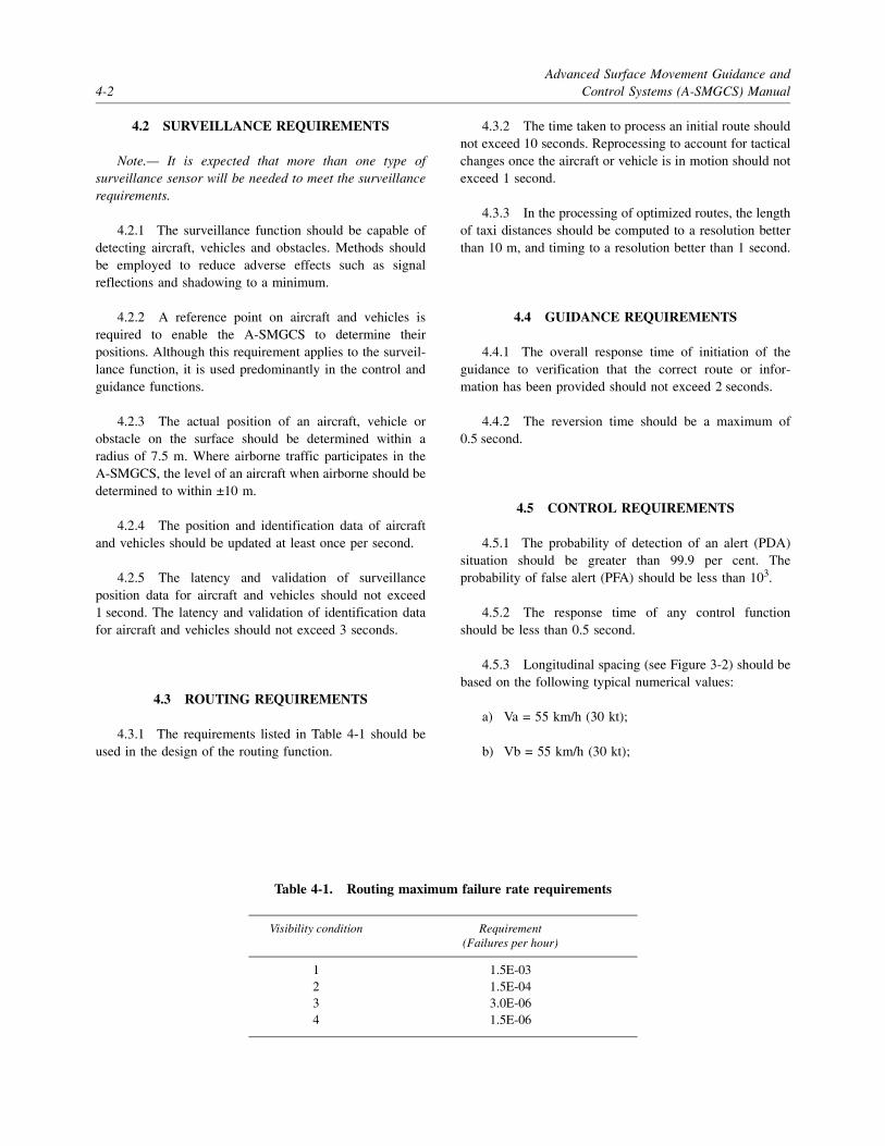
Advanced Surface Movement Guidance and4-2 Control Systems (A-SMGCS) Manual
4.2 SURVEILLANCE REQUIREMENTS
Note.— It is expected that more than one type ofsurveillance sensor will be needed to meet the surveillancerequirements.
4.2.1 The surveillance function should be capable ofdetecting aircraft, vehicles and obstacles. Methods shouldbe employed to reduce adverse effects such as signalreflections and shadowing to a minimum.
4.2.2 A reference point on aircraft and vehicles isrequired to enable the A-SMGCS to determine theirpositions. Although this requirement applies to the surveil-lance function, it is used predominantly in the control andguidance functions.
4.2.3 The actual position of an aircraft, vehicle orobstacle on the surface should be determined within aradius of 7.5 m. Where airborne traffic participates in theA-SMGCS, the level of an aircraft when airborne should bedetermined to within ±10 m.
4.2.4 The position and identification data of aircraftand vehicles should be updated at least once per second.
4.2.5 The latency and validation of surveillanceposition data for aircraft and vehicles should not exceed1 second. The latency and validation of identification datafor aircraft and vehicles should not exceed 3 seconds.
4.3 ROUTING REQUIREMENTS
4.3.1 The requirements listed in Table 4-1 should beused in the design of the routing function.
4.3.2 The time taken to process an initial route shouldnot exceed 10 seconds. Reprocessing to account for tacticalchanges once the aircraft or vehicle is in motion should notexceed 1 second.
4.3.3 In the processing of optimized routes, the lengthof taxi distances should be computed to a resolution betterthan 10 m, and timing to a resolution better than 1 second.
4.4 GUIDANCE REQUIREMENTS
4.4.1 The overall response time of initiation of theguidance to verification that the correct route or infor-mation has been provided should not exceed 2 seconds.
4.4.2 The reversion time should be a maximum of0.5 second.
4.5 CONTROL REQUIREMENTS
4.5.1 The probability of detection of an alert (PDA)situation should be greater than 99.9 per cent. Theprobability of false alert (PFA) should be less than 103.
4.5.2 The response time of any control functionshould be less than 0.5 second.
4.5.3 Longitudinal spacing (see Figure 3-2) should bebased on the following typical numerical values:
a) Va = 55 km/h (30 kt);
b) Vb = 55 km/h (30 kt);
Table 4-1. Routing maximum failure rate requirements
Visibility condition Requirement(Failures per hour)
1 1.5E-032 1.5E-043 3.0E-064 1.5E-06

Chapter 4. Performance Requirements 4-3
c) Aa = 1 to 2 m/s2 (depending on aircraft weight,friction coefficient, etc.);
d) Ab = 1 to 2 m/s2 (depending on aircraft weight,friction coefficient, etc.);
e) Pir = 1 s;
f) Cor = 1 s;
g) Syr = 2 s; and
h) Sar = 1 s.
4.5.4 On the basis of calculations using the abovedata, it can be concluded that:
a) a design taxi speed of 55 km/h (30 kt) is practicable;
b) a longitudinal spacing (St) of approximately 200 m,with aircraft taxiing in trail, will be required toachieve the minima specified below; and
c) a minimum spacing when the aircraft have stopped(Ss + Lj) of approximately 60 to 15 m can beprovided by the system, with the lower figureapplying to holding positions.

5-1
Chapter 5
IMPLEMENTATION ISSUES
5.1 INTRODUCTION
The following paragraphs outline some of the steps thatmight be taken prior to and during the design andimplementation of an A-SMGCS, particularly with respectto the assurance that the A-SMGCS will meet the require-ments of the aerodrome and provide a solution to the safetyand/or capacity problems at the aerodrome.
5.2 CAPACITY ASSESSMENT
5.2.1 General
5.2.1.1 It should be ensured that the system willalways have sufficient capacity to accommodate the aero-drome traffic demand while maintaining a predeterminedcapacity margin, i.e. to ensure a correct capacity/demandbalance (CDB).
5.2.1.2 The CDB should also be used to alert thoseconcerned when demand drops below capacity so thatmeasures can be taken to save resources.
5.2.2 Capacity management
The following different capacities should be taken intoaccount:
a) theoretical capacity — capacity that is calculatedfor existing facilities (layouts, systems, etc.) andcomprises:
1) apron capacity — maximum number of aircraft(with indication of types) that can be parked;
2) taxiway capacity — maximum number ofaircraft that can be operated on the taxiways atthe same time;
3) runway capacity — maximum number ofrunway movements per hour; and
4) approach capacity — maximum number oftransfers between the aerodrome controller andapproach controller.
Each of the above-mentioned capacities should becalculated using both design and operational values, andthey should be referred to in predetermined units of time.
b) downgraded capacity — aerodrome capacity that isderived from the theoretical capacity which hasbeen reduced due to facility limitations (failures,maintenance, weather conditions, local regulations,etc.). The different values should be calculatedtaking into account the following:
1) long term — activities related to storedflight plan arrivals and departures;
2) short term — activities related to en-route,inbound or pre-departure aircraft; and
3) real time — activities related to actualaircraft movements on and in the vicinity ofthe aerodrome.
5.2.3 Demand management
5.2.3.1 As for capacity, the demand should beallocated to the different aerodrome areas (apron, taxiwayand runway), taking into consideration arriving, departingand parked aircraft.
5.2.3.2 To obtain the different demand valuesthroughout the complete time horizon, the system shouldtake into account not only the flight plans and aircrew orairline requests, but also temporary constraints as well asunusual traffic peaks and unexpected arrivals due torestrictions at other aerodromes.

Advanced Surface Movement Guidance and5-2 Control Systems (A-SMGCS) Manual
5.2.4 Mechanisms for balancing demand and capacity
5.2.4.1 Problems will arise whenever the ratiobetween capacity and demand gets closer to one.
5.2.4.2 The value of the predetermined margin, whichwill reflect the uncertainties in assessments of demand andcapacity, must be given to the system in the implementationphase. It should be modified later to reflect experiencegained.
5.2.4.3 The time available for anticipating problemsis a key factor in determining which actions should betaken. The further in advance predictions can be made, thewider the range of options which can be applied.
5.2.4.4 Depending on the time horizons, i.e. frommonths in advance to the actual situation, different actionscan be taken to either modify the demand or the capacity.The following present some of the possible actions:
a) for the long term:
1) increase capacity of the critical (bottleneck)resource; and/or
2) reduce demand for that resource by modifi-cation of stored flight plans (only afterconfirmation that there is no other solution);
b) for the short term:
1) modify flight plans of en-route, inbound ordeparting aircraft; and/or
2) divert arriving aircraft to other aerodromes(only after confirmation that there is no othersolution); and
c) for real time:
1) reallocate slots for departing aircraft.
5.3 COST/BENEFIT ASSESSMENT
5.3.1 General
5.3.1.1 The use of cost/benefit analyses helpsdecision makers to determine the best alternative to systemdevelopment and deployment of equipment and servicessupporting A-SMGCS. While the complexity of aerodrome
surface movement increases as visibility decreases, thebenefits may accrue in increments not directly related tovisibility. For example, if the sharing of information ontake-off delays can produce efficiencies in air trafficmanagement, this benefit could be realized in any visibilitycondition. Those aerodromes developing A-SMGCScapabilities should consider visibility conditions in theircost/benefit analyses, but not as the only factor.
5.3.1.2 Risk analyses can measure the improvementsexpected through changes in procedures or addition oftechnology. Risk analyses produce a probability of an event(i.e. runway incursion, surface collision, etc.). An improve-ment proposed for an aerodrome should show a reductionin risk.
5.3.1.3 Benefits expressed in terms of cost avoidance,aircraft loss, loss of life, disruption to aerodrome services,cost of investigation, etc. can be used to turn risk reductioninto a quantitative value. However, because surfaceaccidents are rare, these cost avoidance savings may be“soft” savings, meaning that they may or may not berealized.
5.3.1.4 Quantifiable benefits tied to efficiency can bedetermined, and improvements assessed against thesebenefits. Savings expected can be measured after theprocedural change or addition of technology. The aero-drome users can validate expected savings in terms ofreduced delay, taxi-in and taxi-out time, aircraft turn-around time at the gate, improved aircraft servicing,improved aerodrome capacity (in terms of throughputexpressed as operations per hour), or reduced operatingcosts. Efficiency benefits accrue with every operation,while safety benefits may remain unseen. Regarding safetybenefits, there are no guarantees that an accident will notoccur, even though risk is reduced.
5.3.1.5 The conduct of cost/benefit analyses will varywith standard economic practices of States and aerodromes.The assessment should provide the basis for modifying theapproach to fit the needs. Those doing cost/benefit analysescan vary from the assessment methodology proposedprovided the ground rules, assumptions and data are madeavailable. This will allow aerodrome users and others toapply their own methodology to determine the benefit fortheir operations.
5.3.2 Cost/benefit guidelines
The primary benefits for operators are related to improvedoperating efficiencies. Aerodrome and air traffic controlbenefits include both safety and efficiency. Safety and

Chapter 5. Implementation Issues 5-3
efficiency benefits should be segregated in the analyses tofacilitate decision making. Guidelines for conducting acost/benefit analysis are listed below:
• Define and provide measures of changes in capacity tothe maximum extent possible. This will allow theaerodrome user to determine whether the capacity gainwarrants improved aircraft equipage.
• Consider benefits which may occur due to avoidance ofcosts associated with diversions and cancellations,including the cost of getting passengers to their finaldestination.
• Identify hourly costs of taxi time, which may be differ-ent from hourly block time costs traditionally used incost/benefit analyses. The taxi time cost is morerepresentative of surface operations cost.
• Consider benefits which may occur due to improvedcommand and control, not just air traffic managementimprovements. The sharing of surveillance informationcan provide command and control benefits for theaerodrome operator and service providers on theaerodrome.
• Use aerodrome traffic growth forecasts or nationalgrowth forecasts to estimate future demand.
• Use historical weather data for projected operatinghours in visibility conditions 1 through 4.
• Wherever possible, incremental analyses should beundertaken so that only the additional benefits of a newinitiative, net of any previous initiatives, can be deter-mined. Modular addition of capabilities to improveservices is the basis of any A-SMGCS implementation.Cost/benefit analyses should be modular also to captureincremental improvements.
• Use current and projected costs and determine overallcost using life-cycle costing. A life-cycle cost estimateincludes the cost of research, engineering and develop-ment, acquisition, operation, decommissioning anddisposal. In the event that an alternative solution orproject requires user equipage, these costs must beincluded. Both non-recurring and recurring costs shouldbe considered. The source of the cost data should beexplained for each major cost element.
• The method of computing cost and benefit valuesshould be explained, including discounting, propor-tional distribution of benefits, yearly distribution ofcosts and benefits, and timing for realizing benefits orincurring costs.
• A module in an A-SMGCS may have value foroperations beyond surface movement. Therefore,analyses should define how benefit and cost segmentsare attributed to surface applications.
• Previously procured systems have already been justi-fied based on their own merits. The cost of sustainingan existing system such as an operational surface move-ment radar should not be charged against an A-SMGCSunless a new radar with improved performance wouldbe required. In this case, a replacement system shouldbe considered as one of the modules for cost/benefitanalyses.
• Non-personnel-related cost avoidance should beconsidered, which may include maintenance savings,reduced telecommunications costs, leases, rents,utilities, and the deferral or elimination of the need tomake a capital investment.
• Secondary user benefits should be identified. AnA-SMGCS produces information as a product. Whetherit be improved surface surveillance, scheduling infor-mation, gate allocations, etc., this information has valueto service providers beyond air traffic control, theaerodrome users and the aerodrome operator.
• System performance trade-offs should be considered inbalancing cost and benefit. There may be opportunitiesto meet the goals of an A-SMGCS through trade-offsin technology and procedures. A good cost/benefitanalysis will consider each alternative and the modulesdefined within the envisioned system. These trade-offsshould be clearly defined so that others reviewing theanalysis and the decision makers can consider them.
5.3.3 Identifying benefits
5.3.3.1 Benefits are improvements realized over theexisting baseline capability. Starting with the operationalrequirements given in this manual, add local, site-specificuser and aerodrome requirements. Compare the existingbaseline operating capabilities to those proposed in the newoperational requirements for an A-SMGCS. Define whogets the benefits. This allocation of benefits will help inquantifying both the benefits and the costs. The allocationwill also help in developing the assumptions that will beused in the analyses.
5.3.3.2 Table 5-1 provides a representative break-down of benefits. This table should be modified, asnecessary, for each particular aerodrome.

Advanced Surface Movement Guidance and5-4 Control Systems (A-SMGCS) Manual
Table 5-1. Benefits breakdown
Service provider benefits
ATM service providers • Controller productivity
• Maintenance productivity
• Leased communications savings
• Rent, utility, other savings
• Liability cost savings
• Future capital cost avoidance
Other air navigation service providers
• Productivity
• Maintenance productivity
• Leased communications savings
• Rent, utility, other savings
• Liability cost savings
• Future capital cost avoidance
• Reduced service cost to user
Aerodrome service providers • Increased capacity (operations per hour)
• Operations productivity
• Maintenance productivity
• Improved passenger handling
• Improved rescue response
• Reduced time when runway(s) unusable
User benefits
Delay savings Air carrier • Aircraft operating cost savings
• Diversion avoidance
• Reduced flight cancellations
Commuter and air taxi • Aircraft operating cost savings
• Diversion avoidance
• Reduced flight cancellations
General aviation • Aircraft operating cost savings
Military aviation • Aircraft operating cost savings
• Improved all weather capability

Chapter 5. Implementation Issues 5-5
User benefits
Safety • Fatalities avoided
• Injuries avoided
• Aircraft losses avoided
• Aircraft damage avoided
• Ground vehicle damages avoided
Efficiency Air carrier • Aircraft operating cost savings
• Aircraft turn-around time reduced
• Personnel savings
• Maintenance savings
• Avoided capital investment cost
Commuter and air taxi • Aircraft operating cost savings
• Aircraft turn-around time reduced
• Personnel savings
• Training savings
• Maintenance savings
• Avoided capital investment cost
General aviation • Aircraft operating cost savings
• Aircraft turn-around time reduced
Military • Aircraft operating cost savings
• Aircraft turn-around time reduced
• Personnel savings
• Maintenance savings
• Avoided capital investment cost
Informationuser efficiencies
• Improvements in command and control
• Improved level of service
• Personnel savings
• Training savings
• Maintenance savings
• Aircraft turn-around time reduced
• Passenger/cargo throughput improvements

Advanced Surface Movement Guidance and5-6 Control Systems (A-SMGCS) Manual
5.3.3.3 Table 5-2 provides a listing of potential usersof information provided by A-SMGCS. The table wasdeveloped to identify primary and secondary users ofinformation. Some aerodrome authorities may restrict theaccess to information provided by an A-SMGCS.
5.3.4 Identifying cost
5.3.4.1 Cost should be defined as life-cycle cost. Inthe past, air traffic control systems were developed with an
expected life cycle of 20 years. This trend is changing withthe introduction of improved, cost-effective automation andreliance on commercial products. An air traffic controlhardware life of 5 to 10 years is becoming more common.Commercial airlines expect a 20-year life cycle for equip-ment installed by the aircraft manufacturer. For equipmentinstalled by the airline, the life cycle is in the order of 5 to7 years for avionics, while the cost recovery for avionics istypically 3 to 5 years.
Table 5-2. Information users
Note 1.— Terminal surveillance allows position and time to be reported for aircraft in the terminal area.
Note 2.— Surface surveillance reports position of aircraft and vehicles in the manoeuvring areas. If surveillance coverageis extended to the ramp area, then surface surveillance will have increased value for control.
Note 3.— Flight plan data provides departure information with gate/stand identified.
Note 4.— Arrival data list contains the expected landing time and gate/stand arrival time, with gate identified.
UserTerminal
surveillanceSurface
surveillance Flight plan data Arrival data list
Air traffic control x x x
Apron management x x x
Operations (airline) x x x x
Operations (aerodrome) x x x x
Maintenance aerodrome x x x
Snow removal team x x x x
Rescue and fire fighting x
Noise monitoring x
Finance (landing fees) x
Flight informationdisplay systems x x
Ground transportation x x
Baggage handling x x
Fuelling x x
Catering x x
Customs and immigration x x
Lodging facilities x x

Chapter 5. Implementation Issues 5-7
5.3.4.2 Table 5-3 contains the user cost breakdown.The project cost breakdown of ground equipment isprovided in Table 5-4. These cost tables show examples ofpotential sources of cost. Each A-SMGCS may producedifferent cost sources. The primary objective is to developa list of applicable cost sources early in the analyses. As inthe benefit analyses, it is important to solicit participationfrom all affected service providers and users early in theprocess.
5.3.4.3 Another metric for economic justification isnet present value — the discounted value of expected netbenefits (i.e. benefits minus costs). In order to compute netpresent value, benefit and cost streams are discounted by aspecified rate. This discount rate may vary with each State.The rate also differs within the user community.
5.3.5 Recommended outline for a cost/benefit analysis and report
It is recommended that an outline for a cost/benefit analysisand report contain:
• A brief summary of objectives, costs, alternativesinvestigated, methodology, and benefits and costsassessed;
• Discussion of any historical data that helps to define theshortfall in capabilities and application of any previouscost/benefit studies which will be used;
• A description of the current baseline, shortfalls in theexisting system, and proposed solutions to overcomingthese shortfalls;
Table 5-3. User cost breakdown
Users Sources of costs
Acquisition • Hardware• Firmware• Software• Installation• Opportunity (out-of-service) costs• Engineering• Integration• Testing and certification• Training development• Management• Cost of funding
Operations • Labour• Training• Leased communications• Facilities• Utilities
Maintenance • Out-of-service cost• Labour• Training• Spares• Logistics• Test equipment• Maintenance management
Information users • Leased communications• Hardware• Software• Training• System maintenance• Utilities

Advanced Surface Movement Guidance and5-8 Control Systems (A-SMGCS) Manual
Table 5-4. Project cost breakdown of ground equipment
Service providers Sources of costs
Project management • Management efforts• Financial management• Planning and scheduling• Contract management• Data management
Systems engineering • Engineering management• Interface management• Configuration management• Quality assurance• Production management• Transition management• Technical monitoring• Operational requirements• System design
Pre-production • Proof of concept• Prototype development• Deployment costs
Prime mission equipment • Hardware• Firmware• Software• Integration• Production/assembly
Testing • Test programme• Developmental testing and evaluation• Operational test and evaluation
Data • Technical manuals• Engineering data• Data depository• Other documentation
Training • Training requirements analysis• Training manuals• Management• Course development• Course delivery
Integrated logistics • Logistics management• Support equipment• Spares• Warehousing• Facility requirements
Site activation • Site procurement• Site survey• Environmental assessments• Site preparation• Site installation and checkout

Chapter 5. Implementation Issues 5-9
• Technical and procedural alternatives that can fulfil themission needs, the characteristics of each alternative,and whether each alternative meets all or a portion ofthe mission needs;
• A description of each ground rule and assumption usedin identifying costs and benefits, including factors usedto discount values;
• A description of methods used to estimate benefits andcosts, equations used, and data sources referenced;
• An assessment of life-cycle costs consistent with theground rules and assumptions used. Parametric, vendorquotes, and analogy methods should be used to estimatelife-cycle costs and extrapolate costs over the life cycle;
• A description of benefits identified, presented in amodular fashion so that incremental benefits can beunderstood;
• A comparison of benefits and costs for each alternativewith a ranking in terms of the most benefit for the leastcost; and
• Levels of confidence of benefit and cost information asdetermined by probabilistic analysis. The effects ofvarying the values of key assumptions should also betested.
5.4 GENERIC METHODOLOGY FORASSESSING CAPABILITIES OFSPECIFIC SYSTEMS TO MEET
A-SMGCS REQUIREMENTS
5.4.1 Introduction
5.4.1.1 The assessment of specific technologiesshould preferably use a standardized methodology so as tohave a baseline reference for each technology that will beassessed. The assessment is an iterative process, whichshould take place in close cooperation between thoseinvolved, i.e. authorities, service providers, operators andmanufacturers.
5.4.1.2 The feasibility of application of varioustechnologies and systems should be proven by a feasibilityassessment, which determines whether a selected tech-nology meets the requirements. This feasibility assessmentcould comprise various techniques, such as theoreticalanalysis, simulation or, simply, data collection.
5.4.1.3 If the assessment takes place according to astandardized methodology, the documented results of theassessment could serve as an element of a certificationprocess and as evidence of the performance of the systemor part thereof up to the operational requirement.
Operational support • Contractor maintenance• Direct work maintenance• Supply support• Support equipment• Training and training support• Leased communications• Facilities• Utilities• Periodic inspection and/or certification
Disposal • Disposal management• Dismantle/decommission• Demolition• Environmental audits• Hazardous waste management• Facility construction or conversion• Site restoration• Salvage value recovery
Service providers Sources of costs

Advanced Surface Movement Guidance and5-10 Control Systems (A-SMGCS) Manual
5.4.2 Generic technology assessmentmethodology
5.4.2.1 The information flow in the assessmentprocess is illustrated in Figure 5-1. Important first stepsinclude the definition of the technology to be assessed, thespecific architecture of this technology, and the role (e.g.the guidance function) that this technology is proposed tofulfil in the A-SMGCS. It is possible that this architecturemay change during the assessment process as difficulties insatisfying certain requirements become apparent. Whensuch a change occurs, it is important to document therevised architecture completely and restart the assessmentprocess from the beginning.
5.4.2.2 In documenting the technology, architectureand role in the A-SMGCS to be assessed, a tabular formatmay be useful to support the text.
5.4.3 Generic assessment parameters
The operational and performance requirements for theA-SMGCS should be broken down into quantitativeperformance parameters and qualitative design guidelines.Where available, a metric has been associated with eachperformance parameter. The resulting generic matrix isintended to provide the basis for assessing a technologywhich is proposed for application in the A-SMGCS.
5.5 SAFETY ASSESSMENT
5.5.1 Introduction
5.5.1.1 Before an A-SMGCS is declared operational,a safety assessment should be made in order to understandthe safety impact caused by the application of the systemand also the safety impact in case of failure of elements ofthe system. The safety assessment should be supported byrelevant documentation, which should be in a format thatenables easy updating after system modification. Thedocumentation should clearly indicate against which safetyobjectives the assessment took place and if these objectiveswere fully met.
5.5.1.2 The safety assessment is not only meant toconvince the authority of the safety of the system but alsoto clearly indicate aspects like training and controls uponwhich the safety depends so that the required safety levelcan be maintained.
5.5.2 System description
In order to perform a safety assessment, a portrayal of thetotal system is required. This portrayal starts with adescription of the system to be assessed. This descriptionshould include:
a) the intended functions of the system including itsmodes of operation;
b) the system performance parameters and theirallowable limits (e.g. what constitutes a failure);
c) the functional and physical boundaries of thesystem and its components;
d) the environmental conditions which the systemneeds to withstand;
e) the interfaces with other systems and with humanoperators (controllers, pilots and vehicle drivers);and
f) functional block diagrams of the system and itsinterfaces.
5.5.3 Hazard analysis
5.5.3.1 The hazard analysis should indicate whatconstitutes a failure condition of the system. The hazardanalysis should focus on the functions and vulnerabilities ofthe system and include:
a) the consequences of a failure of an A-SMGCS or apart thereof to function within its specifiedperformance limits;
b) the consequences of other possible malfunctions ofthe system and their effects on other systems;
c) the consequences to an A-SMGCS of failures inother systems;
d) the identification of possible common-mode orcascade failures (e.g. a failure of a guidance systemthat causes several aircraft to loose their guidance);and
e) the identification of possible sources for errors byhuman operators.
5.5.3.2 The result of the hazard analysis may well bean indication of the need for a system (or part thereof)redesign.

Chapter 5. Implementation Issues 5-11
Figure 5-1. Flow diagram of generic technology assessment methodology
Begin
Definetechnology
andarchitecture
Definerole of technology
inA-SMGCS
Selectfunction
andoperational requirement
Operationalrequirements
Identifyparameters
Identifynumerical value
required
Determineperformance
oftechnology/architecture
Theoretical analysis:
Simulation:
Data collection:
– Failure mode analysis– Hazard analysis
– Monte Carlo technique– Real time– Fast time
– Actual operation simulated
Feasability assessment:
Performancerequirements
End
All functions ando
assessed?perational requirements
YES
NO
Rejectsystem for thisfunction and
operational requirement
NO
YES
Is the performanceOK?
Acceptsystem for thisfunction and
operational requirement

Advanced Surface Movement Guidance and5-12 Control Systems (A-SMGCS) Manual
5.5.4 Failure mode analysis
A failure analysis of the total system is needed todemonstrate compliance with the operational requirements.
5.5.5 Risk allocation
It is necessary to indicate the probability of failure of eachelement of the A-SMGCS in order to ensure a properassessment of the overall safety of the system.
5.5.6 Example of safety assessmentmethodology
5.5.6.1 Each procedure developed for use with anA-SMGCS should undergo a generic safety or risk assess-ment. However, the implementation of the procedures at anaerodrome should require a site-specific risk assessment toensure that all local safety issues are addressed. Onemethod of conducting such a risk assessment is describedin the following paragraphs.
5.5.6.2 Risk assessments should be performed prior toa change to an existing procedure or the introduction of anew procedure, system or type of equipment. The riskassessment should assess all functions and systems, andchanges to them, for their safety significance. Any risksidentified during system introduction should be consistentwith the level of safety established for that procedure,system or equipment. The methodology used and theresults should be fully documented and preferablypresented by the service provider to the safety regulator forapproval.
5.5.6.3 The level of risk for any failure in a functioncan be derived from, and associated with, maximumallowable rates of occurrence. The final step is to identifythe tools or techniques that need to be applied to thespecification, design and testing of the procedures orsystems to provide the required safety assurance.
5.5.6.4 To tolerate a risk means that it is not regardedas negligible or something that might be ignored, but ratheras something that needs to be monitored and reduced ifpossible.
Risk assessment process
5.5.6.5 The generic risk assessment process is asfollows:
a) identify possible safety hazards that could arise,including the failure of any relevant procedure,system or equipment;
b) classify the risk of the identified safety hazard interms of probability of occurrence and thecriticality of effect on aircraft;
c) assess if the risk of the identified safety hazard istolerable; and
d) if the risk is not tolerable, establish mitigatingaction.
5.5.6.6 The methodology used and the results of therisk assessment process should be compiled in a report,which should also describe the new system, procedure oramendment. For each significant risk that is determined, arationale or “argument” for the tolerability of the risk, andthe details of any mitigation used should be provided. Thereport should also outline the management process wherebysafety is monitored and managed. The report should besubmitted to the safety regulator for assessment/approval.
Risk classification
5.5.6.7 In order to ensure that the risk assessment isvalid, it is necessary to have a set of appropriate andconsistently applied definitions of probability of occurrenceand criticality.
5.5.6.8 Risk classification models are already in usein many safety-related industries. Probability of occurrencedefinitions and safety criticality categories used by someStates are presented in Table 5-5 and Table 5-6 respectively.Other models may be used with the agreement of the safetyregulator.
Note 1.— Some risks are dependent on the number ofhours that an aircraft is exposed to risk (per flight hour),and the duration of a flight has an effect on the risk. Thus,the term “per hour” is employed. For aerodrome opera-tions, it is usually more appropriate to use “per operation”as system functionality is normally not time-dependent.
Note 2.— The probability of occurrence is defined inboth qualitative and quantitative terms. In certainapplications a numerical analysis may not be practical, e.g.the rate of failure of a human cannot be expressednumerically with confidence. Also, qualitative assessmentmay be sufficient for events classified as minor or major.

Chapter 5. Implementation Issues 5-13
Table 5-5. Probability of occurrence definitions
Table 5-6. Safety criticality classification
Probability ofoccurrence
classification Extremely improbable Extremely remote Remote Probable
Quantitativedefinition
< 10-9 per flight hour 10-7 to 10-9 per flight hour
10-5 to 10-7 per flight hour
1 to 10-5 per flight hour
Qualitativedefinition
Should virtually never occur in the whole fleet life
Unlikely to occur when considering several systems of the same type but, nevertheless, has to be considered as being possible
Unlikely to occur during total operational life of each system but may occur several times when considering several systems of the same type
May occur once or several times during operational life
Category Catastrophic Hazardous Major Minor
Results in one or more of the
following effects
• The loss of the aircraft
• Multiple fatalities
• A large reduction in safety margins
• Physical distress or a workload such that the flight crew cannot be relied on to perform their tasks accurately or completely
• Serious injury or death of a relatively small proportion of the occupants
• A significant reduction in safety margins
• A reduction in the ability of the flight crew to cope with adverse operating conditions as a result of increase in workload or as a result of conditions impairing their efficiency
• Injury to occupants
• Nuisance
• Operating limitations
• Emergency procedures

Advanced Surface Movement Guidance and5-14 Control Systems (A-SMGCS) Manual
Risk tolerability matrix
5.5.6.9 A risk tolerability matrix defines themaximum rate of occurrence allowed for any particulareffect or event. An example is shown in Table 5-7.
Note 1.— Minor effects are not usually a concern incertification but may well be unacceptable commercially oroperationally.
Note 2.— Table 5-7 shows the minimum safetyperformance standards that may be applied.
5.6 CERTIFICATION
5.6.1 All ground equipment that forms an essentialelement of an A-SMGCS should be certified for its use andbe regularly inspected or reviewed. The aerodrome operatorshould have certified maintenance procedures establishedfor the ground equipment that is essential to the perform-ance of an A-SMGCS.
5.6.2 The certification of airborne equipment shouldbe covered by aircraft certification procedures.
5.6.3 All software used for an A-SMGCS should becertified through a standard software certification pro-cedure.
5.6.4 Any new application or change to an A-SMGCSshould be evaluated by the regulatory authority forcompliance of the system with the operational require-ments. The evaluation should be followed by a formalapproval. Additional requirements or limitations of theoperational use could be stated.
5.6.5 The aerodrome operator and the ATC serviceprovider are responsible for the training and maintenanceprocedures for personnel and equipment under theirjurisdiction. In the certification process, they should be ableto demonstrate that they can perform all tasks required forthe proper functioning of an A-SMGCS.
5.6.6 The manufacturer of an A-SMGCS is respon-sible for the proper documentation of the system conceptand design. Furthermore, evidence of system capabilitiesshould be provided. Depending on the local situation, themanufacturer could have to deal with either the regulatoryauthority or the purchasing organization.
Table 5-7. Risk tolerability matrix
Quantitative probability of occurrence 1 10-1 10-2 10-3 10-4 10-5 10-6 10-7 10-8 10-9
JAR 25 Qualitative probability of occurrence
Frequent Reasonably probable
Remote Extremelyremote
Extremely improbable
Classification of effect Minor Major Hazardous Catastrophic

A-1
Appendix A
A-SMGCS CATEGORIZATION
1. INTRODUCTION
1.1 For guidance on what level of A-SMGCS isappropriate to a specific aerodrome, it is necessary toconsider:
a) visibility conditions;
b) traffic density; and
c) aerodrome layout.
1.2 The criteria proposed for visibility conditions andtraffic density are based on the Manual of Surface Move-ment Guidance and Control Systems (SMGCS) (Doc 9476).
2. VISIBILITY CONDITIONS
2.1 Whereas Doc 9476 (Chapter 2) lists threevisibility conditions for the purpose of discussing SMGCS,a further breakdown of low visibility conditions has beenincluded here. For the purpose of this manual, visibilityconditions are subdivided and defined as follows:
a) Visibility condition 1:
Visibility sufficient for the pilot to taxi and to avoidcollision with other traffic on taxiways and at inter-sections by visual reference, and for personnel ofcontrol units to exercise control over all traffic onthe basis of visual surveillance;
b) Visibility condition 2:
Visibility sufficient for the pilot to taxi and to avoidcollision with other traffic on taxiways and at inter-sections by visual reference, but insufficient forpersonnel of control units to exercise control overall traffic on the basis of visual surveillance;
c) Visibility condition 3:
Visibility sufficient for the pilot to taxi butinsufficient for the pilot to avoid collision withother traffic on taxiways and at intersections byvisual reference, and insufficient for personnel ofcontrol units to exercise control over all traffic onthe basis of visual surveillance. For taxiing, this isnormally taken as visibilities equivalent to an RVRof less than 400 m but more than 75 m; and
d) Visibility condition 4:
Visibility insufficient for the pilot to taxi by visualguidance only. This is normally taken as an RVR of75 m or less.
Note.— The above visibility conditions apply for bothday and night operations.
2.2 When selecting A-SMGCS modules for a particu-lar aerodrome, in addition to the main criteria describedabove, effects of short-term transitory factors, such as lowangle sun glare, twilight, and differing day and night view-ing conditions, should be considered.
2.3 Aerodrome movement rates may include short-term peak loads in excess of normal movement rates. Thismay result in difficulties for ATC to maintain awareness ofthe traffic situation by visual means alone.
3. TRAFFIC DENSITY
3.1 Traffic density is measured from the mean busyhour independent of visibility condition.
3.2 Traffic density is divided into three categories:

Advanced Surface Movement Guidance andA-2 Control Systems (A-SMGCS) Manual
a) Light (L):
No more than 15 movements per runway ortypically less than 20 total aerodrome movements;
b) Medium (M):
16 to 25 movements per runway or typicallybetween 20 to 35 total aerodrome movements; and
c) Heavy (H):
26 or more movements per runway or typicallymore than 35 total aerodrome movements.
4. AERODROME LAYOUT
For aerodrome layout, three levels have been established asfollows:
a) Basic (B):
An aerodrome with one runway, having onetaxiway to one apron area;
b) Simple (S):
An aerodrome with one runway, having more thanone taxiway to one or more apron areas; and
c) Complex (C):
An aerodrome with more than one runway, havingmany taxiways to one or more apron areas.
5. AERODROME TYPES
5.1 By identifying each of the appropriate criteria, itis possible to determine the necessary SMGCS orA-SMGCS modules to support the operational require-ments at a specific aerodrome based on the intendedminimum visibility for operations.
5.2 Considering the criteria at 2.1, 3.2 and 4 in thisappendix, there are 36 combinations which may be relatedto an aerodrome type. These can be grouped for eachvisibility condition as shown in Table A-1.
Table A-1. Combination of aerodrome types
Note.— Appendix B shows a grouping of the aerodrome types appropriate to the level of implementation of A-SMGCSafter considering the necessary functional requirements to maintain A-SMGCS capacity.
Visibilitycondition 1 2 3 4
Aerodrometype
T-1:(B)(L) T-10:(B)(L) T-19:(B)(L) T-28:(B)(L)T-2:(B)(M) T-11:(B)(M) T-20:(B)(M) T-29:(B)(M)T-3:(B)(H) T-12:(B)(H) T-21:(B)(H) T-30:(B)(H)T-4:(S)(L) T-13:(S)(L) T-22:(S)(L) T-31:(S)(L)T-5:(S)(M) T-14:(S)(M) T-23:(S)(M) T-32:(S)(M)T-6:(S)(H) T-15:(S)(H) T-24:(S)(H) T-33:(S)(H)T-7:(C)(L) T-16:(C)(L) T-25:(C)(L) T-34:(C)(L)T-8:(C)(M) T-17:(C)(M) T-26:(C)(M) T-35:(C)(M)T-9:(C)(H) T-18:(C)(H) T-27:(C)(H) T-36:(C)(H)

B-1
Appendix B
A-SMGCS IMPLEMENTATION LEVELS
Criteria for the categorization of aerodromes on the basis ofvisibility conditions, traffic density and aerodrome layoutare given in Appendix A. The appropriate level of func-tional implementation of an A-SMGCS at a particularaerodrome can be determined by identifying the criteriathat apply. There are 36 possible aerodrome type criteriacombinations, 4 functional criteria (surveillance, control,routing and guidance) and 3 user groups (controller, pilot/vehicle driver and system) to consider. Overall, the numberof options is too large to be of practical assistance to
anyone tasked with defining the level of implementationthat is appropriate for a given aerodrome. Table B-1 is anexample of one means of grouping A-SMGCS implemen-tation into 5 levels that together cover all cases. The tableshows that the 4 basic functions are provided at all levels.Within the table, the role played by automation and avi-onics increases progressively through the levels. Level Vcorresponds to the most demanding aerodrome require-ments where the level of automation is the highest.
Table B-1. Criteria for determining A-SMGCS implementation levels
Aerodrometype User Surveillance Control Routing Guidance Level
Conflictprediction
and/ordetection
Conflictanalysis
Conflictresolution Ground
Onboard
*1 *2 *3 *4
T-1: 1:(B)(L)T-2: 1:(B)(M)T-3: 1:(B)(H)T-4: 1:(S)(L) Controller X X X X X I
Pilot/Vehicle driver X X X X
System
T-5: 1:(S)(M)T-6: 1:(S)(H)T-7: 1:(C)(L)T-10: 2:(B)(L)T-11: 2:(B)(M)T-13: 2:(S)(L) Controller X X X X X II
Pilot/Vehicle driver X X X X X
System X X

Advanced Surface Movement Guidance andB-2 Control Systems (A-SMGCS) Manual
T-8: 1:(C)(M)T-12: 2:(B)(H)T-14: 2:(S)(M)T-16: 2:(C)(L)T-19: 3:(B)(L)T-20: 3:(B)(M)T-22: 3:(S)(L) Controller X X X X III
Pilot/Vehicle driver X X1) X1) X
System X X X X X
T-9: 1:(C)(H)T-15: 2:(S)(H)T-17: 2:(C)(M)T-18: 2:(C)(H)T-21: 3:(B)(H)T-23: 3:(S)(M)T-24: 3:(S)(H)T-25: 3:(C)(L)T-26: 3:(C)(M)T-27: 3:(C)(H) Controller X X X IV
Pilot/Vehicle driver X X1) X1) X
System X X X X X X
T-28: 4:(B)(L)T-29: 4:(B)(M)T-30: 4:(B)(H)T-31: 4:(S)(L)T-32: 4:(S)(M)T-33: 4:(S)(H)T-34: 4:(C)(L)T-35: 4:(C)(M)T-36: 4:(C)(H) Controller X X X V
Pilot/Vehicle driver X X
System X X X X X X
*1. Painted centre line and taxiway guidance signs Note 1.— Does not apply in visibility condition 3. *2. Fixed centre line lights*3. Manual switched centre line lights*4. Automatic switched centre line lights
Aerodrometype User Surveillance Control Routing Guidance Level
Conflictprediction
and/ordetection
Conflictanalysis
Conflictresolution Ground
Onboard
*1 *2 *3 *4

C-1
Appendix C
EQUIPMENT EVOLUTION FOR A-SMGCS
Since A-SMGCS are in the early stages of their researchand development, the material in this appendix should onlybe used as a guide. It should not be used to justify technicalspecifications. For each of the possible 36 aerodrome types,Table C-1 indicates the types of equipment that may beneeded to provide the required level of service for each ofthe 4 basic A-SMGCS functionalities. For some of therequirements, equipment has already been fully developedand is in service. In other cases, potentially suitable
equipment has been developed, its technical performancehas been demonstrated, and it may soon be in service. Inyet other cases, equipment research and development are atearly stages. It is important to recognize that equipmentevolution and operational procedures for A-SMGCS will bestrongly influenced by the need for operational safety andefficiency, and the results of tests and evaluations that arecurrently in hand or planned for the future. Table C-1 isprovided purely for illustrative purposes.

Advanced Surface Movement Guidance andC-2 Control Systems (A-SMGCS) Manual
Table C-1. Equipment evolution for A-SMGCS
Aerodrometype
Visib
ility Surveillance system Routing
systemGuidance
systemControl system
Approach Manoeuvring area Apron Conflict
Mov
emen
t Incursionalerts
Protection
Layo
ut
Traf
fic le
vel
Visu
al
Instr
umen
t
Det
ectio
n
Trac
king
Iden
tific
atio
n
Accu
rate
Det
ectio
n
Trac
king
Iden
tific
atio
n
Accu
rate
Rout
e
Rout
e pla
nnin
g
Visu
al a
ids
Situ
atio
n aw
aren
ess
Rest
ricte
d ar
ea
Det
ectio
n
Aler
t
Reso
lutio
n
Runw
ay
Taxi
way
Runw
ay
Taxi
way
1 B L 1 ATCO ATCO P C H,C H,C
2 B M 1 ATCO ATCO P C H,C H,C
3 B H 1 R R ATCO ATCO P C H,C H,C
4 S L 1 ATCO ATCO P C H,C H,C
5 S M 1 SMR ATCO ATCO P C ( ) H,C H,C
6 S H 1 R R ATCO ATCO P C ( ) ( ) ( ) H,C H,C
7 C L 1 R SMR ATCO ATCO P C ( ) H,C H,C
8 C M 1 R ATCO Sys M C ( ) ( ) ( ) H,C H,C
9 C H 1 R R Sys Sys A C H,C H,C
10 B L 2 R SMR ATCO ATCO P C ( ) ( ) H,C,G H,C
11 B M 2 R SMR ATCO ATCO P C ( ) ( ) H,C,G H,C
12 B H 2 R R ATCO Sys M C ( ) ( ) H,C,G H,C
13 S L 2 R SMR ATCO ATCO P C ( ) ( ) H,C,G H,C
14 S M 2 R ATCO Sys M C ( ) ( ) H,C,G H,C
15 S H 2 R R Sys Sys A C ( ) H,C,G H,C
16 C L 2 R ATCO Sys M C ( ) ( ) H,C,G H,C
17 C M 2 R Sys Sys A C ( ) H,C,G,S H,C,T
18 C H 2 R R Sys Sys A C H,C,G,S H,C,T
19 B L 3 R ATCO Sys M C ( ) H,C,G,S H,C,T
20 B M 3 R ATCO Sys M C ( ) H,C,G,S H,C,T
21 B H 3 R Sys Sys A C H,C,G,S H,C,T
22 S L 3 R ATCO Sys M C ( ) H,C,G,S H,C,T
23 S M 3 R Sys Sys A C H,C,G,S H,C,T
24 S H 3 R Sys Sys A C H,C,G,S H,C,T
25 C L 3 R Sys Sys A C H,C,G,S H,C,T
26 C M 3 R Sys Sys A C ,E ,E H,C,G,S H,C,T
27 C H 3 R Sys Sys A C ,E ,E H,C,G,S H,C,T
28-36 All All 4 R Sys Sys A,E C,E E ,E ,E ,E H,C,G,S,E H,C,T,E
Aerodrome types: System Modules:Layout B = Basic R Approach radar S Switched stop bar 1)
Layout S = Simple SMR Surface movement radar 1) T Traffic lightsLayout C = Complex P Painted centre line with/without lights 1) ATCO Air traffic controllerTraffic L = Light M Manually switched (block of) centre line lights 1) Sys SystemTraffic M = Medium A Automatic switched centre line lights New development requiredTraffic H = Heavy C Aerodrome chart and signs 1) ( ) New development desirable
H Holding position marking 1) E Enhanced cockpit displayG Runway guard lights 1)
Note 1.— For details see Table 2-2 of Doc 9476.

D-1
Appendix D
TARGET LEVEL OF SAFETY (TLS)
1. INTRODUCTION
This appendix provides details on the background infor-mation that was used to determine the A-SMGCS targetlevel of safety (TLS). It is necessary to allocate a portion ofthe TLS for an entire flight (one accident per 107
operations) to the A-SMGCS taxi phase. The methodchosen to determine an appropriate TLS for an operationwas to base it on the historical accident and movement rateswithin the European Civil Aviation Conference (ECAC)area. A similar exercise conducted in the United States isalso outlined. Both produce comparable results.
2. ECAC ACCIDENT DATA
2.1 The ECAC study was based on the ICAO“Accident/Incident Data Reporting” (ADREP) system data-base and the number of movements on ECAC aerodromesextracted from ICAO statistics yearbooks (Civil AviationStatistics of the World (Doc 9180)). Flight data from theEUROCONTROL Central Flight Management Unit(CFMU) were used to analyse the number of movementsbut, since this information refers to flights since 1992, itwas only used as reference information.
2.2 The ADREP database was used to collect thenumber and characteristics of ground movement accidentsin ECAC member States from 1980 to 1999. During thistime period, there were 627 recorded accidents from27 ECAC States; of which 52 accidents were fatal orcaused total aircraft destruction. The other 575 accidents,even if they had serious consequences or were “near-misses”, were not included in the study. Of the 52 fatal orhull-loss accidents, 2 occurred as a result of taxi or runwayoperations.
2.3 From 1980 to 1996, there were 150 612 893movements in the ECAC area. However, data have yet tobe published for the period 1997 to 1999; therefore, anannual growth of 5 per cent was estimated. Since the datarefers to principal aerodromes only, a factor of 10 per cent
was applied to the total number of aircraft movements totake into consideration the traffic at non-principal aero-dromes. This gives a total number of movements of165 674 182.
2.4 The above data give an ECAC-wide taxi accidentrate of 2/165 674 182 = 1.2 × 10⁻⁸ per operation. If weconsider that the average taxi time of an aircraft does notexceed 6 minutes, the risk per hour will be 1.2 × 10⁻⁶ perhour. This value compares with a similar analysis,conducted in the United States for A-SMGCS TLS usingworldwide and United States accident data, which isoutlined below.
3. WORLDWIDE AND UNITED STATESACCIDENT DATA
3.1 An analysis to determine a TLS for A-SMGCSthat was performed by a sub-group of the ICAO AllWeather Operations Panel in 1997 considered accident datafor the landing and taxi phases of flight and compared thecalculated risk of a fatal accident within the globalaerodrome operations TLS of 107..
3.2 An analysis of worldwide accident data from1985 to 1994 revealed that the fatal accident rate was1.8 × 10-6 per operation and that taxi accidents accountedfor 5 per cent of fatal accidents. Therefore, the worldwidefatal taxi accident rate was 9.0 × 10⁻⁸ per operation.
3.3 An analysis of National Transportation SafetyBoard (NTSB) data from 1985 to 1994 revealed that thefatal accident rate was 0.56 × 10⁻⁶ per operation and thatfatal taxi accidents accounted for 11 per cent of all fatalaccidents. Therefore, the United States fatal taxi accidentrate was 6.2 × 10⁻⁸ per operation.
3.4 The total TLS defined in developing the approachand landing required navigation performance (RNP) was1.5 × 10-7 per mission. The final approach and landingallocation was 1.0 × 10⁻⁸ per operation.

Advanced Surface Movement Guidance andD-2 Control Systems (A-SMGCS) Manual
3.5 The TLS for A-SMGCS, encompassing the taxiphase of the total flight operations, must fit within thisoverall mission TLS. Another factor is that the accidentdata reflect accidents due to all causes, whereasA-SMGCS-related accidents would constitute only aportion of taxi accidents. Therefore, the A-SMGCS TLSshould not receive the entire allocation of risk related to thetaxi phase of operation.
3.6 As can be seen from the worldwide accidentdata and the NTSB data for aircraft operations in theUnited States, the fatal taxi accident rates are similar(9.0 vs. 6.2 × 10⁻⁸ per operation). As stated before, the
total mission TLS is targeted to be 1.0 × 10⁻⁷. The finalapproach and landing phase was allocated at 1.0 × 10⁻⁸.Similarly, the other phases of flight have allocations thatuse only a small portion of the overall TLS. Therefore, thetaxi phase should be allocated a comparable portion.Based on the above considerations, the A-SMGCS TLS is1.0 × 10-8 per operation. Although the data used in theevaluation were collected during the same time period, itwas considered that the margin of 6 to 9 over thehistorical accident rate is in line with the allocations ofTLS to the various phases of flight used for the approachand landing RNP and, therefore, may be considered a fairconclusion.

E-1
Appendix E
A-SMGCS RESEARCH
1. INTRODUCTION
1.1 This appendix looks at some of the A-SMGCSthat have been the subject of research projects oroperational trials in Europe and the United States.
1.2 The purpose of this appendix is not only todescribe A-SMGCS but to provide some information on thetype of components or sub-systems that may be used todevelop an A-SMGCS suitable for an individual aero-drome.
2. DEMONSTRATION FACILITIES FORAERODROME MOVEMENT MANAGEMENT
(DEFAMM)
2.1 The Demonstration Facilities for AerodromeMovement Management (DEFAMM) was a researchproject that was carried out by fifteen European partnersfrom industry, research institutes, and aerodrome and ATCauthorities, and was sponsored by the European Com-mission1. In DEFAMM, various prototype sub-systemscovering all the main functions of an A-SMGCS weredemonstrated in operational environments, including fourEuropean aerodromes. This was the first large-scaleintegrated system demonstration for aerodrome surfacetraffic management on a European level. The projectcommenced on 1 December 1995 and ended on 31 March1999.
2.2 Four aerodromes participated in the demonstra-tion of the A-SMGCS. Not all of the functions wereimplemented at each demonstration site. This was becausethe total range of the DEFAMM functions formed acomplex system, and a single test site, being also anoperational aerodrome, would have been completely over-loaded. Furthermore, it was desirable to demonstrate that an
A-SMGCS could be profitably embedded in differentenvironments with a variety of aerodrome facilities andtopological constraints. A further advantage was the abilityto use several independent test environments for systemssuch as positioning reference and digitized aerodromemaps.
2.3 DEFAMM functional demonstration
Surveillance function
2.3.1 As the architecture in Figure E-1 shows, thesurveillance function was realized by two non-cooperativesensors and two cooperative sensors. The two non-cooperative sensors were the existing surface movementradar (SMR) with the new radar data extractor electronicscanning radar directly delivering digital target reports. Thetwo cooperative sensors comprised the prototype Mode Smultilateration system with a Mode S central station(mainly for aircraft detection and identification) and adifferential global navigation satellite system (D-GNSS)sub-system with a D-GNSS central station (mainly forvehicles). A cooperative sensor for vehicles was alsodemonstrated to enhance the surveillance capabilities.
2.3.2 The sensor data fusion was implemented on thesensor data processing, which combined the four sensortypes and used data from the aerodrome surveillance radar(ASR) to deliver a unique picture of the traffic situation.The sensor data fusion is a software product, and its task isto track and filter the surveillance data, to provideidentification information of controlled vehicles and tomonitor the traffic situation.
Control function
2.3.3 The sub-system for conflict handling wasrealized on a workstation of the sensor data processingcomputers. The main functions implemented were thedetection and handling of:
1. European Commission DG VII: Air Transport/Airports/Task4.3.1/44.

Advanced Surface Movement Guidance andE-2 Control Systems (A-SMGCS) Manual
a) area violation and intrusion;
b) runway incursion;
c) crossing conflicts;
d) roll-up and opposite traffic conflicts;
e) deviation from assigned route; and
f) deviation from assigned time slots.
Planning function
2.3.4 The following basic planning functions wereimplemented:
a) proposed movement plans (routes and time slots)provided to the controller for:
1) arriving aircraft when at final approach;
2) departing aircraft after start-up request; and
3) selected aircraft or vehicle on request;
b) the means to edit and modify the plans at any timein terms of:
1) route change for new destination;
2) route change for the same destination; and
3) change of plans with respect to new time slots;
c) the means to negotiate the plans with the controller,i.e.:
1) issue plan proposals to the HMI;
2) change status when the plan is accepted by thecontroller; and
3) change status when the plan is cleared by thecontroller; and
d) cleared plans to the guidance processing function.
Guidance function
2.3.5 The guidance processor permitted:
Figure E-1. DEFAMM functional architecture
RadioSubnetworks
ExternalSystems
Air Traffic ServicesAirport SystemsAirline Systems
HMI
ControllerWorkPosition
ROUTINGPLANNING
FlowPlanning
CONTROL
ConflictHandling
SURVEILLANCE
Data FusionIdentification
ASDE
ASDEExtractor
E-scanASDE
Mode SMultilateration
DGPSGUIDANCE
GuidanceProcessing
Visual Aids
COMMUNICATIONMANAGEMENT
Data BaseData Store
TechnicalSys Control
OperationSys Control
AircraftVehicles
Pilot / DriverAssistant Systems
DGPSSensors

Appendix E. A-SMGCS Research E-3
a) manual or automated switching of centre line lightsegments and stop bars according to the taxi planand the current situation of the aircraft or vehicles;and
b) clearance negotiation and automated transmissionof taxi plan and guidance commands via data linkand the on-board display system.
2.3.6 Guidance with the aerodrome ground lightingwas implemented to:
a) guide the aircraft or vehicles according to the routeof the cleared plan with selectively switchabletaxiway centre line lights;
b) allow manual switching of the taxiway centre linelights; and
c) allow manual switching of the stop bars.
2.3.7 Guidance with the on-board display (pilot/driverassistance system) was implemented to:
a) display the aircraft’s/vehicle’s own position on theaerodrome with respect to the assigned route;
b) support the negotiation of taxi plans (e.g. requestclearance, receive clearance and accept clearance);and
c) display the cleared movement plan (e.g. taxi routeand time slots).
2.3.8 An addressable sign that was able to visuallydisplay the correct route was tested at a complex junctionwhere six taxiways converged. At this junction, some pilotswould slow down or stop in order to find their taxi route.The aim of the addressable sign was to improve the taxiingefficiency. The signs were remotely controlled by ATC viathe A-SMGCS. The aircraft’s call sign and the parkingdestination were displayed on the left screen while theintended taxi route was displayed graphically on the rightdisplay (see Figure E-2).
Communication function
2.3.9 The communication function comprised a timedivision multiple access (TDMA) VHF data link sub-network and performed the following three main tasks:
1. Every second, it transmitted the D-GNSS positionreports of the equipped aircraft or vehicles to thesurveillance function;
2. It distributed the D-GNSS correction information tothe aircraft or vehicles; and
3. It exchanged data for the on-board guidance (i.e.clearance negotiation and transmission of clearedmovement plans).
Figure E-2. Addressable sign on test during the DEFAMM functional demonstration

Advanced Surface Movement Guidance andE-4 Control Systems (A-SMGCS) Manual
Human-machine interface (HMI)
2.3.10 Two different types of HMIs were provided: acontroller working position (CWP) and the HMI of thepilot/driver assistance system (PDAS). The CWP consistedof two visual display units that displayed the current trafficsituation. One screen was used to enlarge a particularportion of the surveyed area.
2.3.11 The negotiation of taxi plans was supported byentering a clearance request via predefined keys on anon-board display, which was then transmitted via data linkto the ground system. The received clearances weredisplayed on the screen of the PDAS. Approved movementplans were displayed on the screen as a taxi route, withtime slots at waypoints. The positions of the aircraft or
vehicle and other equipped aircraft or vehicles were alsodisplayed on the PDAS screen.
3. OPERATIONAL BENEFIT EVALUATIONBY TESTING AN A-SMGCS (BETA PROJECT)
3.1 The BETA project was also funded by the Euro-pean Commission from 2000 to 2001. The project involvedthe operational testing of system components (based onearly drafts of this manual) installed at three Europeanairports. The systems comprised surveillance sensor equip-ment and computers from different manufacturersintegrated with the existing airport and ATC equipment andinfrastructure to provide the first full-scale implementationof A-SMGCS within Europe (see Figure E-3).
Figure E-3. BETA functional architecture
Planningfunction
Guidancefunction
Surveillance and alertingfunctions
Non-cooperative sensors
Cooperative sensors
SMR
NRNSurveillance data
server
Mode S /ADS-B
DGPSData link
ASRE2000
Alertprocess
Fusionprocess
Surface movementplanning system
GDPS
TRP
D-MAN
Guidancesystems
Data link
AGLAMS
Loocal area network
Airport/ATMinformation systems
FDPSESUP
METIDP
Referenceclock
System management
Technicalcontrol andmonitoring
system
Controller HMI
Towercontrollerworkingposition
Groundcontrollerworkingposition
Aproncontrollerworkingposition
Recordingand
playbacksystem

Appendix E. A-SMGCS Research E-5
3.2 The system testing covered the following aspects:
a) surveillance:
1) detection and presentation of traffic and obsta-cles on the aerodrome movement area andapproaches;
2) automatic identification of suitably equippedcooperating traffic, including arriving aircraft;
3) departing aircraft, if equipped with activeMode S transponders;
4) participating vehicles (data link equipped testvans and service vehicles); and
5) manual identification of other targets;
b) alerting:
1) runway occupied/runway incursion alerting forarrivals and departures;
2) restricted area intrusion alerting;
3) crossed stop bar alerting; and
4) route deviation alerting;
c) planning:
1) flight plan presentation;
2) creation, modification and editing of flightplans (including VFR and vehicles);
3) electronic flight strips;
4) handover;
5) departure sequence proposal; and
6) selection of taxiway route;
d) guidance:
1) stop bars;
2) on-board guidance;
3) clearance delivery; and
4) route indication; and
e) controller HMI:
1) traffic situation display; and
2) planning display.
3.3 The BETA equipment was provided in anon-redundant configuration, focusing on data integrity,accuracy and usability.
4. FAA RUNWAY INCURSIONREDUCTION PROGRAMME
4.1 In 2000, trials started in the United States underthe FAA Runway Incursion Reduction Programme (RIRP)2
to evaluate new technologies for A-SMGCS.
4.2 RIRP surveillance system
Figure E-4 shows a block diagram of the RIRP surveillancesystem. At the heart of the system is the surface surveil-lance data server (SSDS). The SSDS receives surveillanceand flight plan information from a variety of sources and“fuses” the information into one optimal report for userdisplay. The surveillance information comes from a varietyof cooperative and non-cooperative sensors, includingterminal and surface radar, inductive loops, automaticdependent surveillance — broadcast (ADS-B), and multi-lateration. The flight plan information is received from thelocal automation system, an automated radar terminalsystem (ARTS), via the flight plan unit. The majority ofinformation is passed between sub-systems over the LAN.It is expected that the system will be modular to meet thesurveillance requirements of various aerodromes in theUnited States.
4.3 Sensor inputs
The RIRP prototype demonstration system will acceptvarious surveillance inputs, including the following:
a) ASDE-3: The ASDE-3 is a primary radar intendedfor aerodrome surface surveillance. It maintains a
2. “1998 Airport Surface Operations Safety Plan to PreventRunway Incursions and Improve Surface Operations”,Runway Incursion Program Office (ATO-102), FAA; 1998.
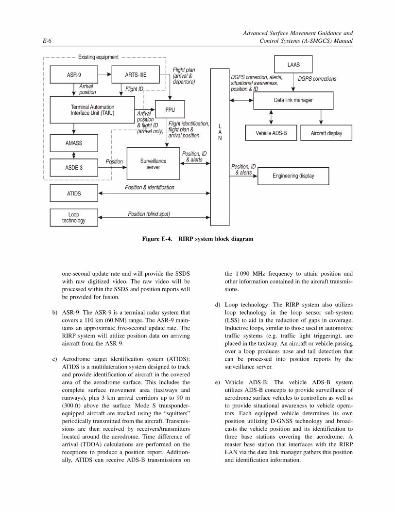
Advanced Surface Movement Guidance andE-6 Control Systems (A-SMGCS) Manual
one-second update rate and will provide the SSDSwith raw digitized video. The raw video will beprocessed within the SSDS and position reports willbe provided for fusion.
b) ASR-9: The ASR-9 is a terminal radar system thatcovers a 110 km (60 NM) range. The ASR-9 main-tains an approximate five-second update rate. TheRIRP system will utilize position data on arrivingaircraft from the ASR-9.
c) Aerodrome target identification system (ATIDS):ATIDS is a multilateration system designed to trackand provide identification of aircraft in the coveredarea of the aerodrome surface. This includes thecomplete surface movement area (taxiways andrunways), plus 3 km arrival corridors up to 90 m(300 ft) above the surface. Mode S transponder-equipped aircraft are tracked using the “squitters”periodically transmitted from the aircraft. Transmis-sions are then received by receivers/transmitterslocated around the aerodrome. Time difference ofarrival (TDOA) calculations are performed on thereceptions to produce a position report. Addition-ally, ATIDS can receive ADS-B transmissions on
the 1 090 MHz frequency to attain position andother information contained in the aircraft transmis-sions.
d) Loop technology: The RIRP system also utilizesloop technology in the loop sensor sub-system(LSS) to aid in the reduction of gaps in coverage.Inductive loops, similar to those used in automotivetraffic systems (e.g. traffic light triggering), areplaced in the taxiway. An aircraft or vehicle passingover a loop produces nose and tail detection thatcan be processed into position reports by thesurveillance server.
e) Vehicle ADS-B: The vehicle ADS-B systemutilizes ADS-B concepts to provide surveillance ofaerodrome surface vehicles to controllers as well asto provide situational awareness to vehicle opera-tors. Each equipped vehicle determines its ownposition utilizing D-GNSS technology and broad-casts the vehicle position and its identification tothree base stations covering the aerodrome. Amaster base station that interfaces with the RIRPLAN via the data link manager gathers this positionand identification information.
Figure E-4. RIRP system block diagram
Existing equipment
ASR-9 ARTS-IIIE
Arrivalposition Flight ID
Terminal AutomationInterface Unit (TAIU) Arrival
position& flight ID(arrival only)
Position
AMASS
ASDE-3
ATIDS
Looptechnology
Position & identification
Position (blind spot)
Flight plan(arrival &departure)
DGPS correction, alerts,situational awareness,position & ID
Flight identification,flight plan &arrival position
LAN
FPU
Surveillanceserver
Position, ID& alerts
Engineering display
Position, ID& alerts
Vehicle ADS-B Aircraft display
Data link manager
DGPS corrections
LAAS

Appendix E. A-SMGCS Research E-7
f) ARTS-IIIE: The ARTS-IIIE automation systemprovides flight plan information for arriving anddeparting aircraft.
g) Local area augmentation system (LAAS): A LAASground station provides D-GNSS corrections.These corrections will be available on the LANthrough the data link manager for various systemsto up-link them to aircraft and vehicles.
4.4 Outputs
The system also has the capability to provide situationalawareness of aircraft and other targets from the SSDS, aswell as runway hold bar information, to users, including thefollowing:
a) Aircraft displays: Traffic and safety alerts can beup-linked, via the data link manager utilizing thevehicle ADS-B system, from the SSDS to develop-mental displays in aircraft. Figures E-5 and E-6illustrate two moving map displays for use inaircraft or vehicles to indicate routing and conflictalert information.
b) Controller displays: The SSDS will provide acolour display for ATC. For each aircraft, thedisplay will show an optimal position report andidentification. Additionally, the display will showincursion alerts and holding position information.
c) Data link manager (DLM): The DLM serves as agateway between the RIRP LAN and externalsystems. These systems include the vehicle ADS-Bsystem, the LAAS ground station, and future data
Figure E-5. Cockpit arrival moving map display

Advanced Surface Movement Guidance andE-8 Control Systems (A-SMGCS) Manual
link communication projects. The DLM provides aninterface for target reports to be exchanged betweenthe vehicle ADS-B system and the RIRP LAN, aswell as providing the safety alerts from the RIRPsystem to be up-linked to vehicles and aircraft.
d) Vehicle operator displays: As previously men-tioned, the vehicle ADS-B system will provideposition, identification and safety alert informationto vehicle operators.
4.5 On-board guidance
4.5.1 The RIRP system trials included the ability ofan aircraft (or vehicle) to perform and maintain a taxi routein visibility conditions of 75 m RVR or less.
4.5.2 In visibility condition 4, the operational andperformance requirements for the surveillance, routing and
control functions should account for the ability of anaircraft to self-navigate on the movement area. Thesefunctions may be wholly contained within the avionics orprovided by data link from an aerodrome A-SMGCS.
4.5.3 Position estimation error values, as outlined inTable E-1, are based on an allocation of the total systemerrors relative to minimum aerodrome runway, taxiwayand apron design requirements specified in Annex 14,Volume I.
4.5.4 The allocations are made to accommodatesufficient path steering errors for various aircraft types, andthey are based on operational and simulator performancedata.
4.5.5 The longitudinal position estimation errorsassigned in Table E-1 are based on the assumption that theguidance sensor achieves the same level of performance inall horizontal directions.
Figure E-6. Cockpit departure moving map display

Appendix E. A-SMGCS Research E-9
4.5.6 As an example, Figure E-7 illustrates the keytaxiway design standards for aerodrome reference codeletter E, which gives a margin of 15.5 m between the wingtips and any objects, including the wings of aircraft onparallel taxiways. The minimum margin between the mainwheels and taxiway edge is 4.5 m. The standards alsorecommend a shoulder of 10.5 m, thus yielding a margin of15 m between the wheels and outer edge of the shoulder.
The result is that the aircraft can deviate by 15 m from thetaxiway centre line before there is risk of an incident, andtherefore the containment limit is defined to be this value.
4.5.7 The containment limit of 15 m is applicableonly to aerodromes of codes D and E. Since the margin isless for aerodromes of codes A, B and C, the containmentlimit for those cases is accordingly defined to be 8 m.
Table E-1. Lateral and longitudinal position estimation errors required for on-board guidance
Figure E-7. Taxiway design standards for aerodrome code letter E aircraft
— END —
Aerodrome code
Lateral and longitudinal position estimation errors (95% in metres)
Rapid exit,normal and apron
taxiways Stand taxilane Stand
A 0.4 0.4 0.3
B 0.6 0.4 0.3
C 0.8 0.5 0.4
D 1.1 0.6 0.5
E 1.1 0.6 0.5
Wing span = 65 m, Wheel span = 14 m
Taxiway width = 23 m Outer wheels taxiway edgesafety margin = 4.5 m
Wing tip to objectsafety margin = 15.5 m
Outer wheels to shouldersafety margin = 15 m
Taxiway center line(desired path)
Taxiway shoulder width = 10.5 m
Containment region =object free area (OFA) = ±47.5 m
Containment limit

ICAO TECHNICAL PUBLICATIONS
The following summary gives the status, and alsodescribes in general terms the contents of the variousseries of technical publications issued by theInternational Civil Aviation Organization. It does notinclude specialized publications that do not fallspecifically within one of the series, such as theAeronautical Chart Catalogue or the MeteorologicalTables for International Air Navigation.
International Standards and RecommendedPractices are adopted by the Council in accordance withArticles 54, 37 and 90 of the Convention onInternational Civil Aviation and are designated, forconvenience, as Annexes to the Convention. Theuniform application by Contracting States of thespecifications contained in the International Standards isrecognized as necessary for the safety or regularity ofinternational air navigation while the uniformapplication of the specifications in the RecommendedPractices is regarded as desirable in the interest ofsafety, regularity or efficiency of international airnavigation. Knowledge of any differences between thenational regulations or practices of a State and thoseestablished by an International Standard is essential tothe safety or regularity of international air navigation. Inthe event of non-compliance with an InternationalStandard, a State has, in fact, an obligation, underArticle 38 of the Convention, to notify the Council ofany differences. Knowledge of differences fromRecommended Practices may also be important for thesafety of air navigation and, although the Conventiondoes not impose any obligation with regard thereto, theCouncil has invited Contracting States to notify suchdifferences in addition to those relating to InternationalStandards.
Procedures for Air Navigation Services (PANS)are approved by the Council for worldwide application.They contain, for the most part, operating proceduresregarded as not yet having attained a sufficient degree of
maturity for adoption as International Standards andRecommended Practices, as well as material of a morepermanent character which is considered too detailed forincorporation in an Annex, or is susceptible to frequentamendment, for which the processes of the Conventionwould be too cumbersome.
Regional Supplementary Procedures (SUPPS)have a status similar to that of PANS in that they areapproved by the Council, but only for application in therespective regions. They are prepared in consolidatedform, since certain of the procedures apply tooverlapping regions or are common to two or moreregions.
The following publications are prepared by authorityof the Secretary General in accordance with theprinciples and policies approved by the Council.
Technical Manuals provide guidance andinformation in amplification of the InternationalStandards, Recommended Practices and PANS, theimplementation of which they are designed to facilitate.
Air Navigation Plans detail requirements forfacilities and services for international air navigation inthe respective ICAO Air Navigation Regions. They areprepared on the authority of the Secretary General onthe basis of recommendations of regional air navigationmeetings and of the Council action thereon. The plansare amended periodically to reflect changes inrequirements and in the status of implementation of therecommended facilities and services.
ICAO Circulars make available specializedinformation of interest to Contracting States. Thisincludes studies on technical subjects.

© ICAO 20046/04, E/P1/1640
Order No. 9830Printed in ICAO