dna fundamentals of digital logic
TRANSCRIPT
03-02-2010 DNA'10 - Aalborg University 2
GoalsUnderstand basics of digital circuits
transistorsboolean logic → logic gatesgates → integrated circuitscountersfeedback – keeping bits in check
03-02-2010 DNA'10 - Aalborg University 3
BackgroundVoltage: difference of potentials.
Vcc – ground (=0).Volts (V)
Current: flow of electrons.Amperes (A)
Ohm’s law: U = RIDissipated power: P = UI = RI2 = U2/R
03-02-2010 DNA'10 - Aalborg University 4
Typical ChipsOperate on low voltage (5V, less for processors) – see power dissipation.Always 2 lines
ground (0V)power (5V)
Diagrams usually omit ground and power.
03-02-2010 DNA'10 - Aalborg University 5
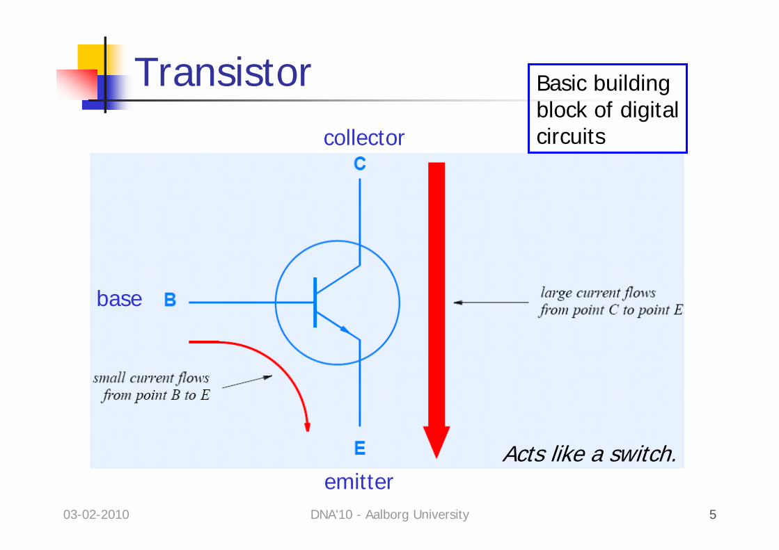
Transistor Basic buildingblock of digitalcircuits
Acts like a switch.emitter
base
collector
03-02-2010 DNA'10 - Aalborg University 6
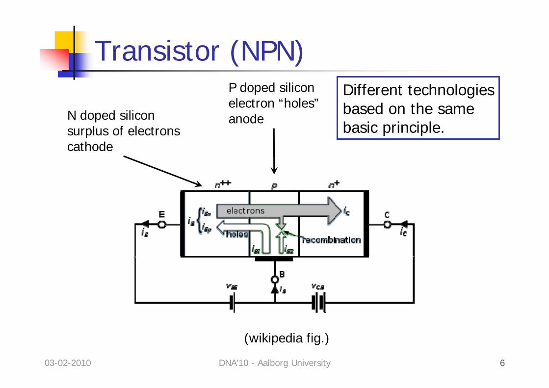
Transistor (NPN)P doped siliconelectron “holes”anodeN doped silicon
surplus of electronscathode
(wikipedia fig.)
Different technologiesbased on the samebasic principle.
03-02-2010 DNA'10 - Aalborg University 7
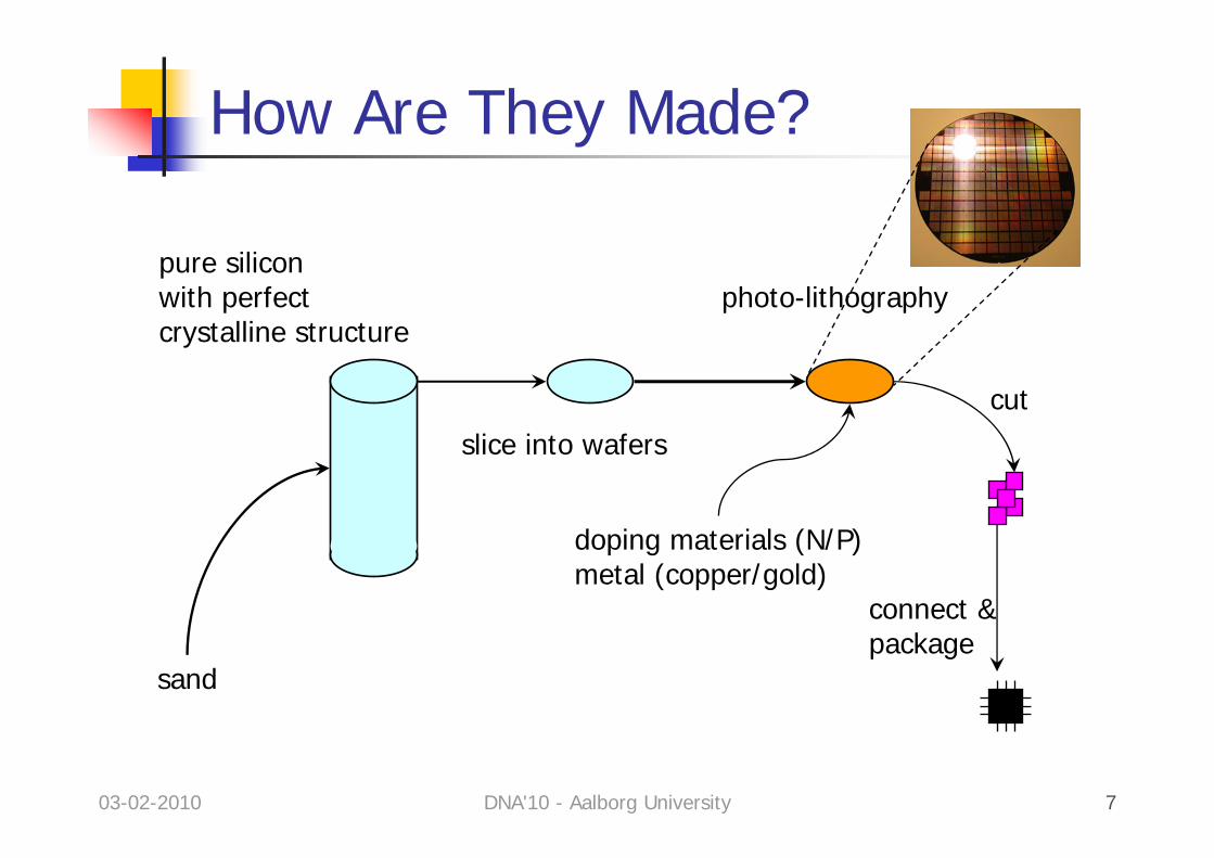
How Are They Made?
sand
pure siliconwith perfectcrystalline structure
slice into wafers
photo-lithography
doping materials (N/P)metal (copper/gold)
cut
connect &package
03-02-2010 DNA'10 - Aalborg University 8
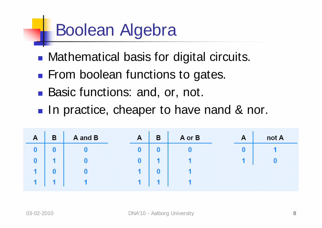
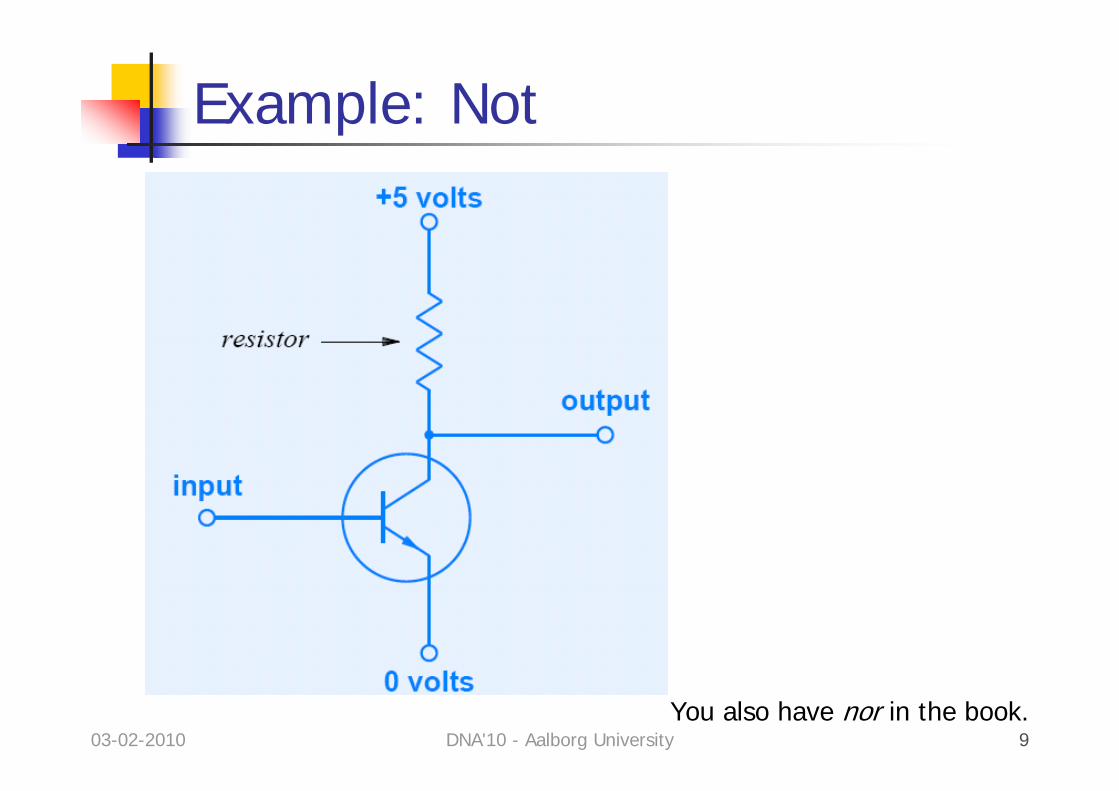
Boolean AlgebraMathematical basis for digital circuits.From boolean functions to gates.Basic functions: and, or, not.In practice, cheaper to have nand & nor.
03-02-2010 DNA'10 - Aalborg University 9
Example: Not
You also have nor in the book.
03-02-2010 DNA'10 - Aalborg University 10
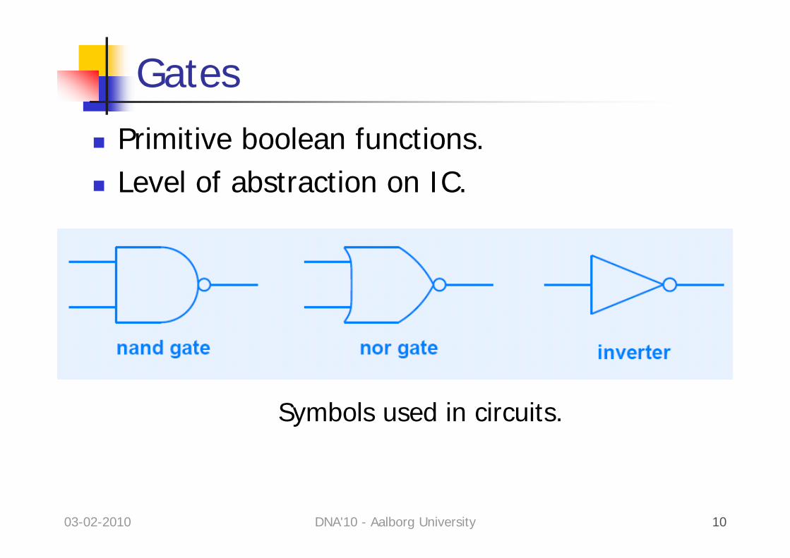
GatesPrimitive boolean functions.Level of abstraction on IC.
Symbols used in circuits.
03-02-2010 DNA'10 - Aalborg University 11
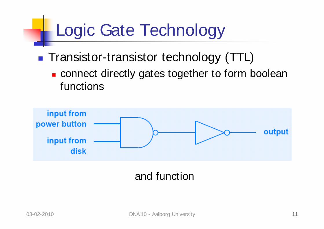
Logic Gate TechnologyTransistor-transistor technology (TTL)
connect directly gates together to form boolean functions
and function
03-02-2010 DNA'10 - Aalborg University 12
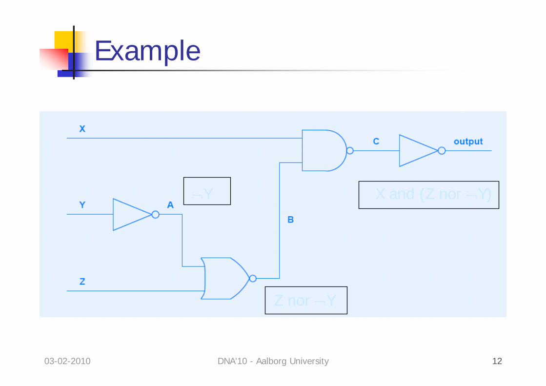
Example
¬Y
Z nor ¬Y
X and (Z nor ¬Y)
03-02-2010 DNA'10 - Aalborg University 13
Design of FunctionsFind a boolean expression that does what you need
and feed it to a tool that optimizes it to minimize the number of gates.
Come up with the truth table of your functionwhich is converted to a boolean function.
03-02-2010 DNA'10 - Aalborg University 14
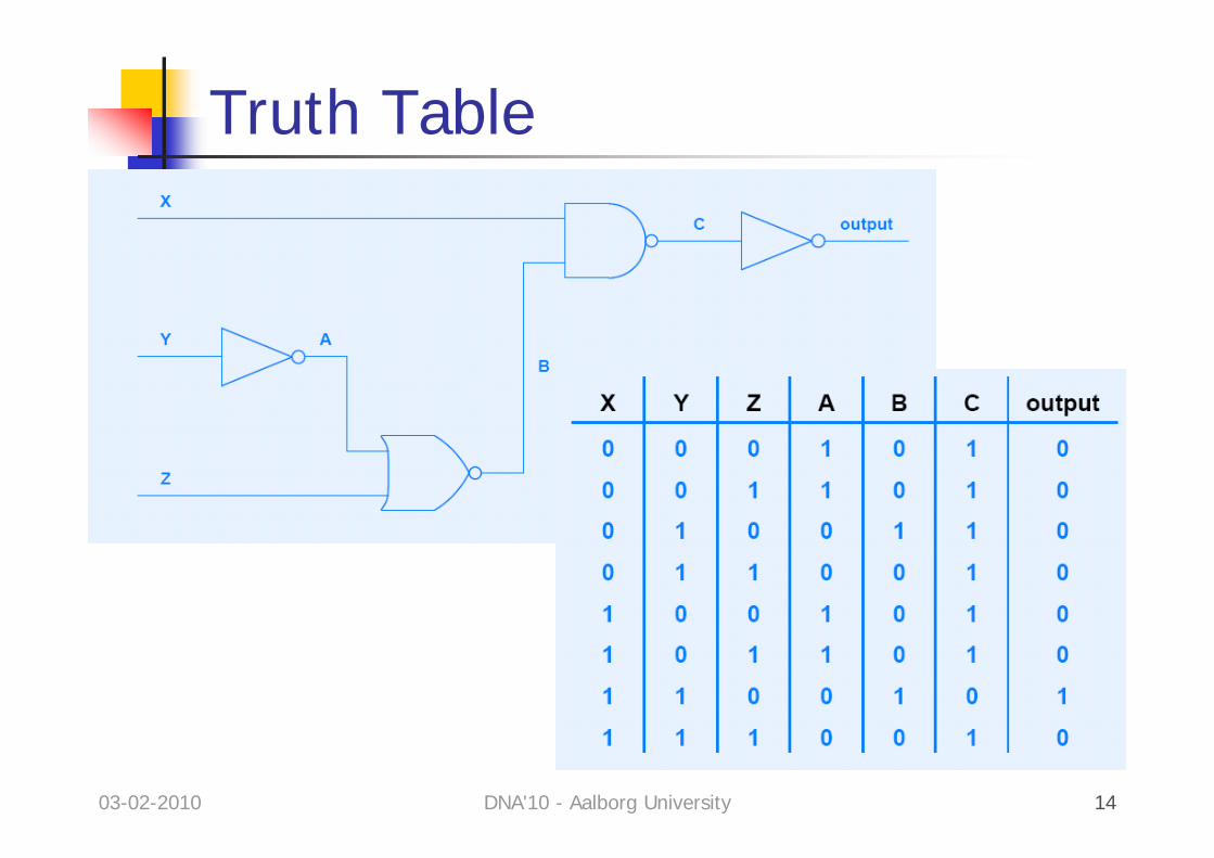
Truth Table
03-02-2010 DNA'10 - Aalborg University 15
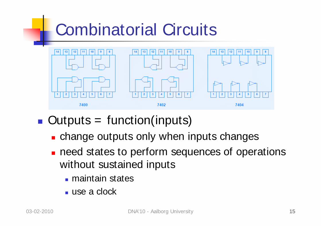
Combinatorial Circuits
Outputs = function(inputs)change outputs only when inputs changesneed states to perform sequences of operations without sustained inputs
maintain statesuse a clock
03-02-2010 DNA'10 - Aalborg University 16
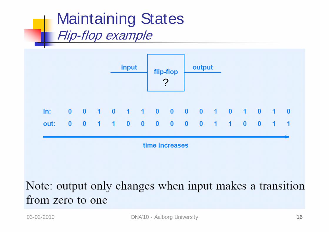
Maintaining StatesFlip-flop example
?
03-02-2010 DNA'10 - Aalborg University 17
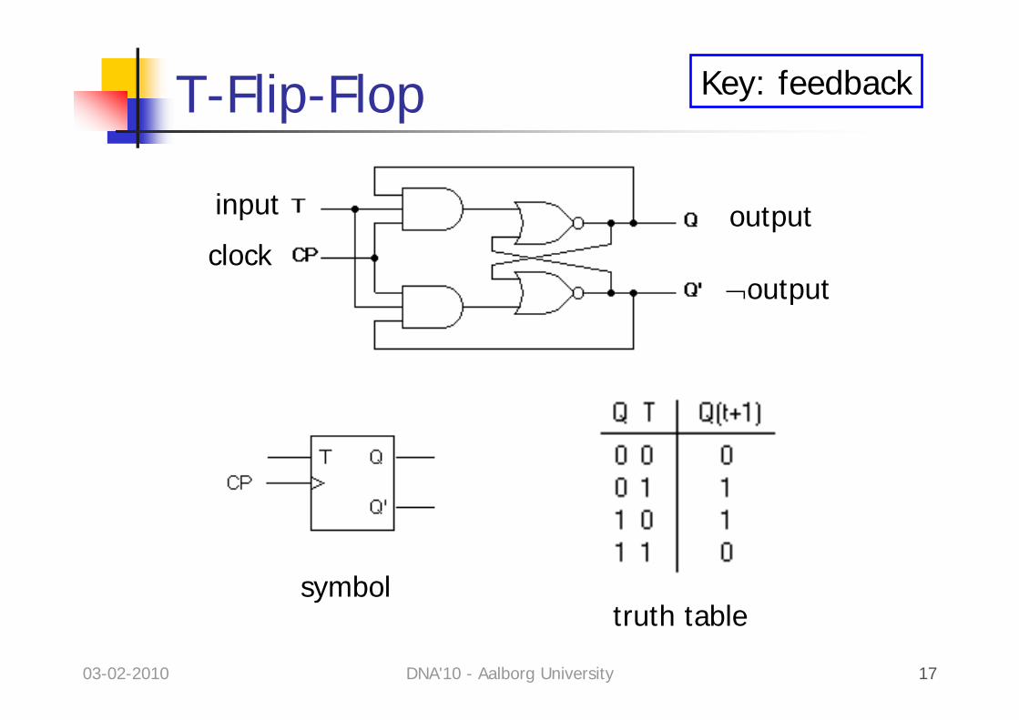
T-Flip-Flop
clock
input output
¬output
symboltruth table
Key: feedback
03-02-2010 DNA'10 - Aalborg University 18
To KnowCan occur on leading or falling edge of the clock signal.Variants of flip-flops.Transition diagrams used to visualize the function.Key: feedback to “keep” the bits.Simple not loop = base for memory bit (cache).
RAM: simpler with a “condensator”more compact but needs to be refreshed
03-02-2010 DNA'10 - Aalborg University 19
Binary CountersCount input pulses.Output = binary number.The IC keeps previous states
→ combines with new inputs to get new output→ combination = boolean function
03-02-2010 DNA'10 - Aalborg University 20
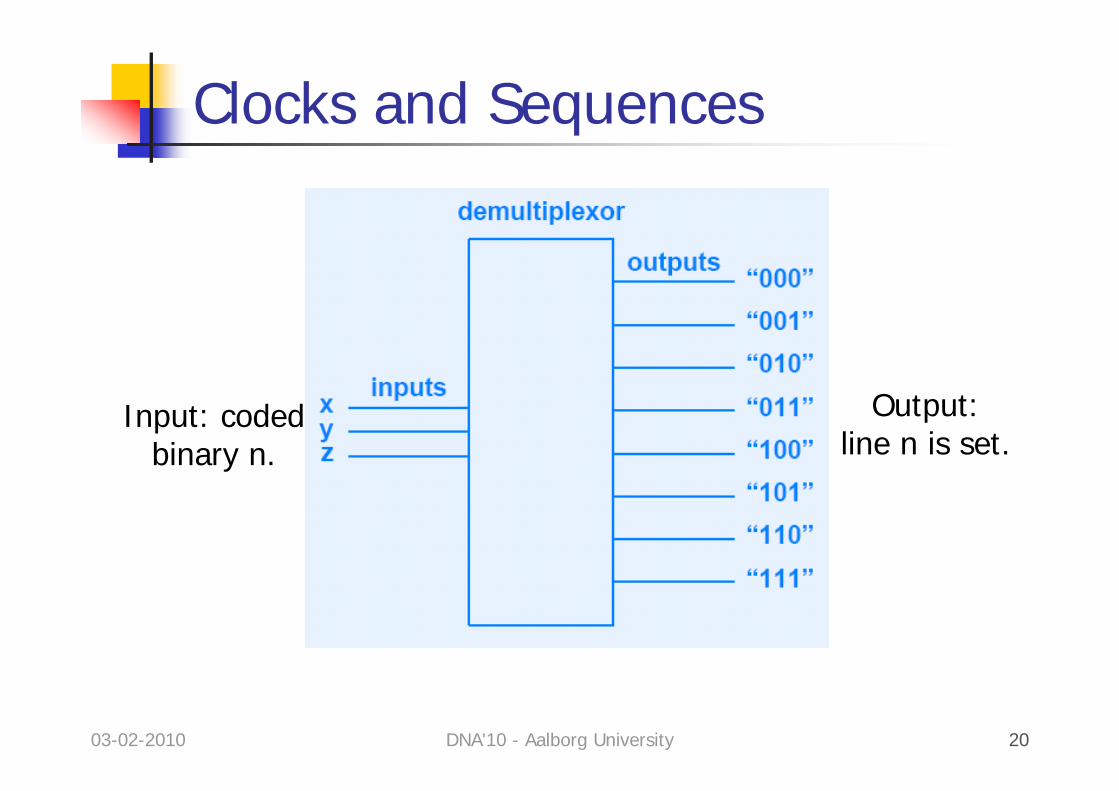
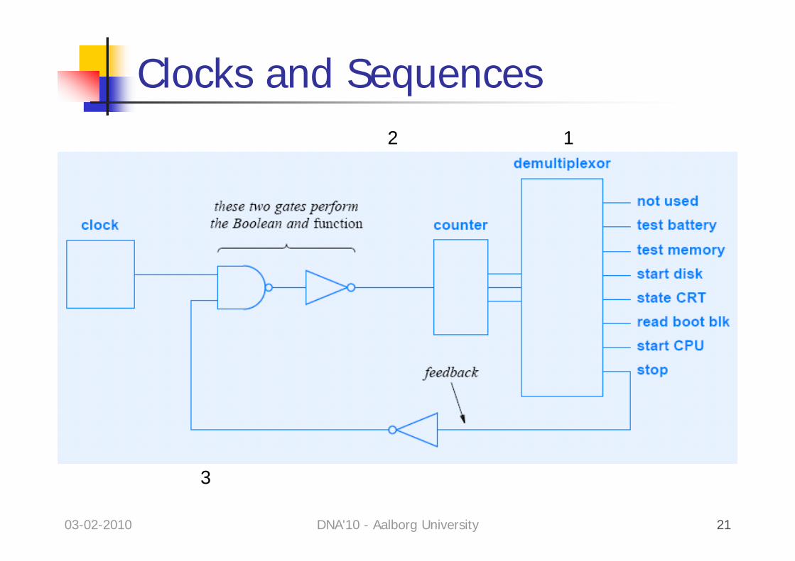
Clocks and Sequences
Input: codedbinary n.
Output:line n is set.
03-02-2010 DNA'10 - Aalborg University 21
Clocks and Sequences12
3
03-02-2010 DNA'10 - Aalborg University 22
Software vs. HardwareSoftware: iterations common.
Avoid replication.
Hardware: replication easier & faster.Iteration clumsier.
Major difference: parallelism.
03-02-2010 DNA'10 - Aalborg University 23
Practical ConcernsPower
consumption: how to feeddissipation P=CFV2 (C: capacitance, F: frequency)how not to burn
Timing – gates need time to settle.Clock synchronization.
03-02-2010 DNA'10 - Aalborg University 24
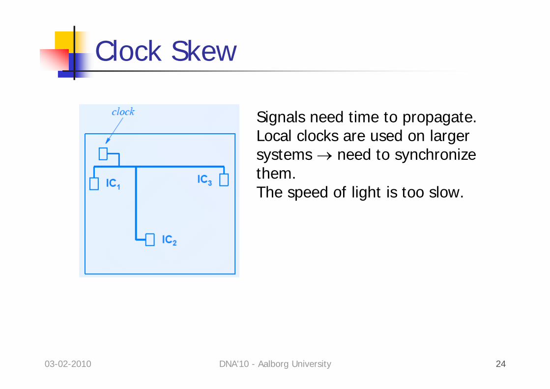
Clock Skew
Signals need time to propagate.Local clocks are used on largersystems → need to synchronizethem.The speed of light is too slow.
03-02-2010 DNA'10 - Aalborg University 25
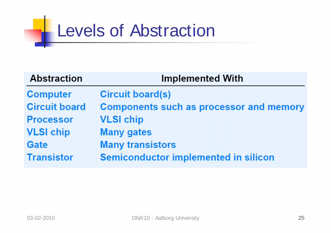
Levels of Abstraction