dmu employee’s saving and credit association information …
TRANSCRIPT

DMU EMPLOYEE’S SAVING AND CREDIT
ASSOCIATION INFORMATION MANAGEMENT SYSTEM
PROJECT REPORT
Submitted by
Name ID
1. Awoke Kerebh…………………………………………TER/4646/07
2. Zewdineh Bawoke……………………………………..TER/4704/07
3. Jenet Sultan ……………………………………………..TER/4668/07
4. Hymanot Ewunetie……………………………………..TER/4666/07
In partial fulfillment for the award of the degree of
BACHELOR OF SCIENCE IN INFORMATION TECHNOLOGY
Under the guidance of
Teshome F
……………………
Signature
DEPARTMENT OF INFORMATION TECHNOLOGY
COLLAGE OF TECHNOLOGY
DEPRE MARKOS UNIVERSITY
DBRE MARKOS
January, 2010 E.

i
Abstract
The purpose of this project is to develop a Web Based employee’s saving and credit association
information management System for Debre markos University, the system reduces the time and
labor required to provide services, Reduce the error that made by the employees, change the
manual storage mechanisms into computerized system (database), provide fast, efficient,
flexible, reliable and secured services for better satisfaction of customers and improves the
motivation of the employees. The existing system of the organization is facing different
problems such as data redundancy, lack of data security and lots of paper work. To solve this
problem the project team used different data collection methods such as Interview, Document
analysis and Practical observation. In order to analyze and design the system we used Object
oriented approach for both analyzing and designing the new system.
To change the current manual system to a web based, needed different software and hardware
tools such as PHP, MYSQLI and others

ii
Acknowledgment
First of all we would like to thank GOD for making us able to perform our tasks well, without
the will of GOD everything is impossible. We have a great thanks and appreciation to our
advisor Teshome F for his excellent advice and supervision.
Next we’d like to thank our classmates and friends for their wellness to give important
information and ideas for us. And also we would like to thank association employees for their
good approach at interview time and wellness at giving important information for us.
Generally we will extend our thanks and appreciation to all individuals that give important
information to us.

iii
Table of Contents
Abstract .......................................................................................................................................................... i
Acknowledgment .......................................................................................................................................... ii
Acronym ....................................................................................................................................................... v
List of tables ................................................................................................................................................. vi
List of figures .............................................................................................................................................. vii
CHAPTER ONE ........................................................................................................................................... 1
1. INTRODUCTION ................................................................................................................................... 1
1.1 Introduction ....................................................................................................................................... 1
1.2 Background of the project ................................................................................................................. 1
1.3 Problem statement ............................................................................................................................. 1
1.4 Objective of the project ..................................................................................................................... 2
1.4.1 General objective ......................................................................................................................... 2
1.4.2Specific objective .......................................................................................................................... 2
1.5 Scope of the project .......................................................................................................................... 3
1.6 Significance of the project ................................................................................................................ 3
1.7 System requirement .......................................................................................................................... 4
1.7.1 Hardware requirement .................................................................................................................. 4
1.7.2 Software requirement ................................................................................................................... 4
1.7.3 Programing language ................................................................................................................... 4
1.8 Data collection methodology ............................................................................................................ 5
Design Methodology ............................................................................................................. 5 1.8.1
1.8.2 Data gathering technique ............................................................................................................ 5
1.9 Feasibility study ................................................................................................................................ 6
1.9.1 Operational feasibility .................................................................................................................. 6
1.9.2 Economic feasibility .................................................................................................................... 6
1.9.3 Technical feasibility ..................................................................................................................... 6
1.9.4 Legal feasibility............................................................................................................................ 6
CHAPTER TWO .......................................................................................................................................... 7
2. SYSTEM ANALYSIS ............................................................................................................................ 7
2.1 Overview of the existing system ......................................................................................................... 7
2.2 System requirement specification ....................................................................................................... 8

iv
2.2.1 Functional requirement ................................................................................................................ 8
2.2.2 Nonfunctional requirement .......................................................................................................... 9
2.2.3 Business rule ................................................................................................................................ 9
2.3 System requirement analysis ............................................................................................................. 10
2.3.1 Actor and use case identification ............................................................................................... 10
2.3.2 Use case diagram ....................................................................................................................... 15
2.3.3 Use case description ................................................................................................................... 17
2.3.4 Sequence diagram .......................................................................................................................... 23
2.3.5 Activity diagram ............................................................................................................................ 29
2.3.6 Analysis class diagram ............................................................................................................... 33
CHAPTER THREE .................................................................................................................................... 35
3. SYSTEM DESIGN ................................................................................................................................. 35
3.1 Design class diagram ........................................................................................................................ 35
3.2. Class diagram description ................................................................................................................ 37
3.3 Database design ................................................................................................................................ 39
3.3.1Physical data model .................................................................................................................... 40
3.4 User interface design ......................................................................................................................... 42
3.5 System architecture (deployment design) ......................................................................................... 47
CHAPTER FOUR ....................................................................................................................................... 48
4 IMPLEMENTATION ................................................................................ Error! Bookmark not defined.
4.1. Over view of the programming language used ................................................................................ 48
4.2 Algorithm used .................................................................................................................................. 48
4.3 sample code ....................................................................................................................................... 49
CHAPTER FIVE ........................................................................................................................................ 55
5 CONCLUSION AND RECOMMENDATION .................................................................................... 55
5.1 Conclusion ........................................................................................................................................ 55
5.2 Recommendation and future enhancement ....................................................................................... 55
Reference .................................................................................................................................................... 57

v
Acronym
CPU central processing unit
CSS cascade style sheet
DMU Debre Marko’s University
GB giga byte
GHZ giga hertiz
GUI graphical user interface
HRM human resource management
HTML hypertext markup language
PHP Hyper Text Pre processor
RAM random access memory
UC Use Case
UML unified model language
vi
List of tables
Table 1 use case identification .................................................................................................................... 12
Table 2 use case description for login ......................................................................................................... 17
Table 3 use case description for register customer ..................................................................................... 18
Table 4 use case description for create user account .................................................................................. 19
Table 5 use case description for send loan request ..................................................................................... 20
Table 6 use case description for approve loan request ................................................................................ 21
Table 10 description of customer class ...................................................................................................... 37
Table 11 description of admin class ............................................................................................................ 38
Table 12 description of manager class ........................................................................................................ 38
Table 13 description of loan table .............................................................................................................. 39
Table 14 description of request table .......................................................................................................... 39
Table 15 employee table ............................................................................................................................. 40
Table 16 customer table .............................................................................................................................. 41
Table 17 response table ............................................................................................................................... 41
Table 18 meeting table ................................................................................................................................ 42
Table 19 feedback table .............................................................................................................................. 42

vii
List of figures
Figure 1 use case diagram ........................................................................................................................... 16
Figure 2 sequence diagram for login ........................................................................................................... 24
Figure 3 sequence diagram for register customer ....................................................................................... 25
Figure 4 sequence diagram for create account ............................................................................................ 26
Figure 5 sequence diagram for send loan request ....................................................................................... 27
Figure 6 sequence diagram for view balance .............................................................................................. 28
Figure 7 Activity diagram for login ............................................................................................................ 29
Figure 8 Activity diagram for create account ............................................................................................. 30
Figure 9 Activity diagram for send loan request ......................................................................................... 31
Figure 10 Activity diagram for view balance ............................................................................................. 32
Figure 11 Analysis class diagram ............................................................................................................... 34
Figure 12 design class diagram ................................................................................................................... 36
Figure 13 login page ................................................................................................................................... 43
Figure 14 admin page create account .......................................................................................................... 44
Figure 15 register customer ........................................................................................................................ 45
Figure 16 send request ................................................................................................................................ 46
Figure 17 deployment design ...................................................................................................................... 47

1
CHAPTER ONE
1. INTRODUCTION
1.1 Introduction
As we know today, the world is in technological area so the world is being coming to one
village. As a result, we should to develop an automated system for Debre Marko’s university
credit association management system.
Debremarkos university employee’s saving and credit association is an organization under the
control of Debremarkos university employees that provides saving and credit services for
employees in the university that wants to use the services. The association manages different
employees like accountants, cashers, and other members
This system provided service to employees of Debre Marko’s university for saving and loan
money. In once credit association the using of money must be performed properly.
1.2 Background of the project
Debre Marko’s university employee’s saving and credit association was initially established in
JUNE 1999 E.C. at the time of establishment there were 77members. The current number of
members in the association is 1023.Among those members 319 are females and 704 are males.
At the beginning of the association there were no regular accountants, among the members of the
association candidates accountants were working. Currently there are 2 regular accountants.
The project is helpful to keep detail information about members, keep record of all modification
and it provides security using login form and using encryption mechanism that are not done in
the existing system. The system what we are going to develop solves the problems of the existing
systems work
1.3 Problem statement
There are many problems in Debre markos university employees ‘saving and credit association
of the existing system since every processes are paper based and users information are copied
more than one paper. Generally processing user information in the existing system takes excess
time, costs and effort.

2
Some of the problems are:
The customer can’t easily view his/her balance:- since the system is paper based it
is difficult to view balance easily
Difficult to shares information easily in the association:- information sharing
among parents is time consuming
Post meeting date is difficult and time consuming:- because the meeting date must
be uploaded on different areas of the campus in order to late the members it
Transaction report is presented two times within a year :- since it is paper based it
is difficult to present report monthly
Calculating loan and deposit interest is difficult and not free from errors:-because
all the calculation processes are performed by the accountant so errors may be
occurred
Giving response for loan request takes long time:-since there are many processes to
response for loan request it is time consuming by the current system
The customer must be registered on three papers:-used to protect data from lost
1.4 Objective of the project
1.4.1 General objective
The general objective of the proposed system is to develop web based employee’s saving and
credit association information management system for Debre Marko’s university.
1.4.2Specific objective
The specific objectives of the proposed system is list of objectives that are useful to achieve the
general objectives
To develop a system that registers and modifies member information easily.
To develop a system that calculate loan and deposit interest easily
To develop a system that can generate monthly report
To develop a system that shares information easily in the association
To develop a system that provides fast services.
To develop a system that makes members able to view their balance easily.
To develop a system that makes members to send requests easily.

3
To develop a system that makes members to view response easily.
1.5 Scope of the project
The scope of the project covers the development of web based employee’s saving and credit
association information management system in Debre Markos University.
The proposed system supports only employees that are working in Debre Marko’s University to
be a member and get service like request loan and deposit money.
The proposed system performs different tasks some of are:
Register new member
Send loan request
View response
view balance
Provide information to the users/generate report
Limitation
The system do not have a link with bank
1.6 Significance of the project
The significance of a project can be categorized into different areas depending up on to whom
the benefit goes.
For Customer
Reduce the time and labor required to get services from the association.
To give/accept necessary information easily.
It enhances accuracy, speed, and security of services.
For their better satisfaction with fast services provided by the employees
Enables the user to interact with the system easily because the system is user friendly
For employees
The system takes the calculate loan and deposit interest tasks that are performed by the
employees in the existing system
reducing the broad manual work
For association
Reduce the cost because of reduced number of employee.

4
The system makes the association database accurate and secured.
1.7 System requirement
System requirements are the hardware and software components of a computer system that are
required to do the proposed system and simply identify tools and methodology
1.7.1 Hardware requirement
Hardware requirements are the physical part that can be touchable and visible components that
are necessary to develop a system. The hardware required to develop the proposed system are:
Personal computer (PC): almost all tasks of our project are performed on computer.
RAM 4GB: To store the file temporarily
CPU Intel(R) Core(TM) i3-4160 CPU @ 3.60GHz: used to process instruction
Hard disk: store large file permanently
1.7.2 Software requirement
The software requirements are the instructional components used to develop a system. Software
requirement to develop system are as follows:
Windows 7: will be used for the system since it is readily available more compatible in
laboratories.
MYSQLI server:-for designing the database
Microsoft office Word:-for documenting the corresponding deliverables associated with the
project
Microsoft office Visio: -to design Unified Modeling Language (UML) diagrams.
GUI software: - to draw user interface of the system.
WAMP Server: -to test the system by running.
1.7.3 Programing language
Programming language is important to complete the system in the best way and to make it good,
easy and interactive with the customer.
The programming languages required to develop a system are:-
PHP: because it is
Easier to fix problems-PHP indicates easily where the problem occurred
Increased efficiency & usability - PHP provides incomparable efficiency and usability
when it is used for the development of websites.

5
Compatible- PHP is compatible on all operating systems including Windows and UNIX-
among other systems.
Data processing - A website that has been developed using the PHP functions has fast
features of data processing.
Easy to understand - When compared with other scripting languages, PHP can be
understood easily because it has simple techniques and features.
Html:-to display the web page.
CSS:-for the formatting of the system.
Java Script: for data validation
1.8 Data collection methodology
Data collection methodology is the systematic approach to gathering and measuring information from a
variety of sources to get a complete and accurate picture of an area of interest
Design Methodology 1.8.1
To design the system, the project team has chosen Object Oriented Modeling techniques and
unified modeling language tools. Reason for choosing:
It enables us to comprehensively model a system before we develop it.
Modification of the object implementation is easy because objects are loosely coupled.
Understanding of the structure is easy because object oriented modeling and tools used to
represent real world entities.
1.8.2 Data gathering technique
1.8.2.1 Interview
We made an interview questions with the employees of debre markos university employee’s
saving and credit association to get information that are useful for developing our system.
1.8.2.2 Observation
We observed the working mechanism of the existing system
1.8.2.3 Document analysis
We read the document which is prepared by the association that explains about the association
feature.
6
1.9 Feasibility study
It is an analysis of the ability to complete a project successfully, taking into account legal,
economical, technological, operational and other factors.
1.9.1 Operational feasibility
It is the measure of how well the solutions for problems will work in the association.
The project will be beneficial because it satisfies the objectives when developed and used. And
as well the new system brings an easy and user friendly working environment that helps the
employees get services from anywhere as well as the association workers to handle tasks easily.
1.9.2 Economic feasibility
Economic feasibility is the analysis of a project's cost benefit analysis in an effort to determine
whether or not it is logical and possible to complete. Our proposed project is economically
feasible because it has less expensive when compared to the existing system, so the project helps
in reducing the cost.
1.9.3 Technical feasibility
It’s a measure of whether the proposed system is user friendly and enables users to maintain
when problems occur or not.
Our system is technically feasible due to the following reason:-
Member can adapt the system easily.
No need of much more skill
Developed with in the latest technology.
Users can maintain problems easily.
1.9.4 Legal feasibility
We need to make sure that the proposed project will meet all legal and ethical requirements of
the project are applied. The system we are going to developed is not conflict with any
government directives or cannot interfere with any political issue and with any cultural aspects.
So our project is legally feasible

7
CHAPTER TWO
2. SYSTEM ANALYSIS
2.1 Overview of the existing system
How the existing system works?
In the existing system generating the overall report of the organization is done manually and also
the association accepts feedback from customer only on the meeting date because of manual
working.
The accountant in the association registers customer and their information such as customer
name, phone number, occupation, address. The customer saves money monthly according to
his/her income by agreement with the association. There are forms available for customer to be
filled by their information such as their name, address, and account number and so on, when they
want to save or take loan money.
To request for loan the customer must go to the HRM enters applicant, and then go to the
association and asks for loan, the accountant in the association register the request and forwards
it to the loan committee, according to the customer capacity to loan the loan committee approve
or deny the request and forwards the response to the main committee, the main committee
forwards it to the manager and the manager forward to accountant, the accountant gives loan
money for the customer if the request is approved. The accountant calculates the saving and loan
interest rate for the customer of the association.
To request for withdraw the customer must go to the association, the accountant in the
association register the request and forwards it to the manager and send back to accountant.
In general, the existing system of DMU employee’s saving and credit association is difficult to
access and manage customer’s account because all the activities are done manually.
Users of the existing system
Manager: a person who manages and coordinates the system activities.
Loan committee: to approve or deny loan request
Accountant: a person who calculate saving and loan interest rate, generate report, register
customer
8
Customer: The people who get service like loan money, deposit money and withdrawal
money from the association.
HRM officer: To check the customer is the member of university and free from loan at
the time of loan request
Finance officer: Snip from salary for deposit and loan.
2.2 System requirement specification
A System Requirements Specification (SRS) is a document or set of documentation that
describes the features and behavior of a system or software application. It includes a variety of
elements that attempts to define the intended functionality required by the customer to satisfy
their different users. In addition to specifying how the system should behave, the specification
also defines at a high-level the main business processes that will be supported. (2)
2.2.1 Functional requirement
Functional requirement is described as what the system is done by identifying the necessary task,
action or activity that must be accomplished. User requirement that are all about the functionality
of the system. These kinds of requirement are directly related to the system, to user, and
stockholders. (3)
The proposed system has the following functional requirements:-
Accountant register new customer
Accountant registers loan money.
Accountant updates customer information up on it required.
System calculate interest rate for loan and deposit money
Customer view their balance
Manager announces meeting date.
Accountant view report such as amount of deposit money, amount of loan money,
amount of customer.
Manager view report such as amount of deposit money, amount of loan money, amount
of customer.
Customer send feedback
System administrator block user
System administrator register employee

9
Customer send loan request
Manager view withdraw request
Manager view approve loan request
Accountant view approve loan request checked by manager
Loan committee view loan request
2.2.2 Nonfunctional requirement
Non-Functional requirement explains and describes requirements that support the system but
they are not part of the system functionalities. Generally nonfunctional requirements describe the
quality of the system.
Technical requirement
Technical requirements are the technical issues that must be considered to successfully complete
a project.
Availability: - the customer to access the system at any time 24/7 hour.
Performance: Since the system is web based the deliver response time of the system should be
very fast. It perform its activity that are relating to the vote is accurately.
Speed: -The system has quick response time.
Security- this system has user name and password to login to the system for perform the tasks
and also the data base uses the encryption methods in order to protect the data.
Effectiveness- can user’s complete task, achieve goals with the product
Error handling: - This system allows minimize error by displaying the message box or the system warns
the users who make errors.
2.2.3 Business rule
A business rule is an operating principle or policies that must be fulfilled in order to the system
function properly and effectively. It often pertain to access control issues, business calculations,
or operating polices and principles of the organization.
BR1: when customers want to get service they must be registered first to the association

10
RB1: the customer before send loan request applicant in human resource management
BR3: the minimum amount of money to loan is 50 birr
BR4: In order to get loan the loan request must be approved by the loan committee
BR5: the customer must be an employee of this university
BR6: the customer can’t take loan more than ones until it repays 1/3 of the loan
BR7: the maximum amount of loan money the member can take is 5times of the
deposited money.
2.3 System requirement analysis
2.3.1 Actor and use case identification
Actor identification
An actor represents anything or anyone that interacts with your system. This may include people,
external systems, and other organizations.
List of actor:
System Administrator: controls the overall system
Manager
Loan committee
HRM officer
Finance officer
Accountant
Customer

11
Use case identification
A use case describes a sequence of actions that provide something of measurable value to an
actor
Use case name Use case ID Include
Login UC1
Register employee UC2 Login
View feedback UC3 Login
Manage account UC4 Login
View employee UC5 Login
View new customer UC6 Login
View meeting date UC7 Login
Change password UC8 Login
Back up DB UC9 Login
Restore DB UC10 Login
View log file UC11 Login
Post meeting date UC12 Login
View withdraw request UC13 Login
View loan close request UC14 Login
View approve loan UC15 Login
Revise meeting date UC16 Login
View monthly report UC17 Login
Register customer UC18 Login
Register repay money UC19 Login
Register issue money UC20 Login
Send report for deposit UC21 Login
Update customer info UC22 Login
View customer UC23 Login
View notification UC24 Login
View receipt UC25 Login

12
Table 1 use case identification
View reported response UC26 Login
View loan request UC27 Login
Approve loan request UC28 Login
Reject loan request UC29 Login
Register debtor UC30 Login
Register representative UC31 Login
View debtor UC32 Login
View representative UC33 Login
Transfer money UC34 Login
View deposit report UC35 Login
View loan report UC36 Login
Send request UC37 Login
cancel request UC38 Login
View response UC39 Login
View balance UC40 Login
Approve withdraw request UC41 Login
Reject withdraw request UC42 Login
Logout UC43 Login

13
Actor: system Administrator:
Register employee
View employee
Manage account
View new customer
Back up DB
Restore DB
View log file
view feedback
view meeting date
Change password
Actor: manager:
post meeting date
View withdraw request
View loan close request
View approve loan
Approve withdraw request
Reject withdraw request
Revise meeting date
View monthly report
View feedback
View employee
Change password
Actor: accountant:
register customer
register repay money
register issue money
send report for deposit
view monthly report
update customer information

14
view customer
view approved request
view notification
view receipt
view reported response
view meeting date
view feedback
change password
Actor: customer
send request
cancel request
view response
view balance
send feedback
view meeting date
change password
Actor: loan committee
view loan request
approve loan request
reject loan request
view meeting date
change password
Actor: HRM officer
register debtor
register representative
view debtor
view representative
change representative
change password

15
Actor: finance officer
view deposit report
view loan report
transfer money
view feedback
change password
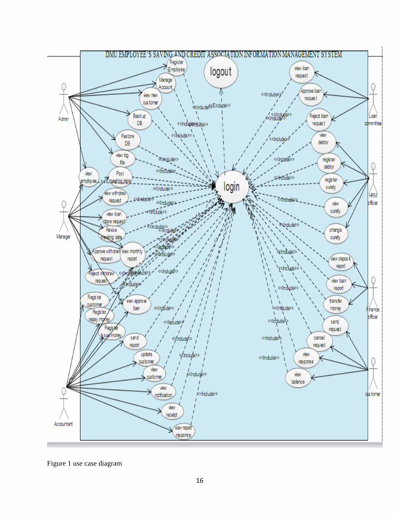
2.3.2 Use case diagram
A use case diagram is a graphic depiction of the interactions among the elements of a system.
Use case diagrams consist of actors, use cases and their relationships. The diagram is used to
model the system/subsystem of an application. (4)
Boundary: - indicates the scope of your system.
Actors: - An actor is a person, organization, or external system that plays a role in one or
more interactions with your system.
Use cases, which the specific roles are played by the actors within and around the system.
relationships:- relationships between actors and the use cases
16
Figure 1 use case diagram
17
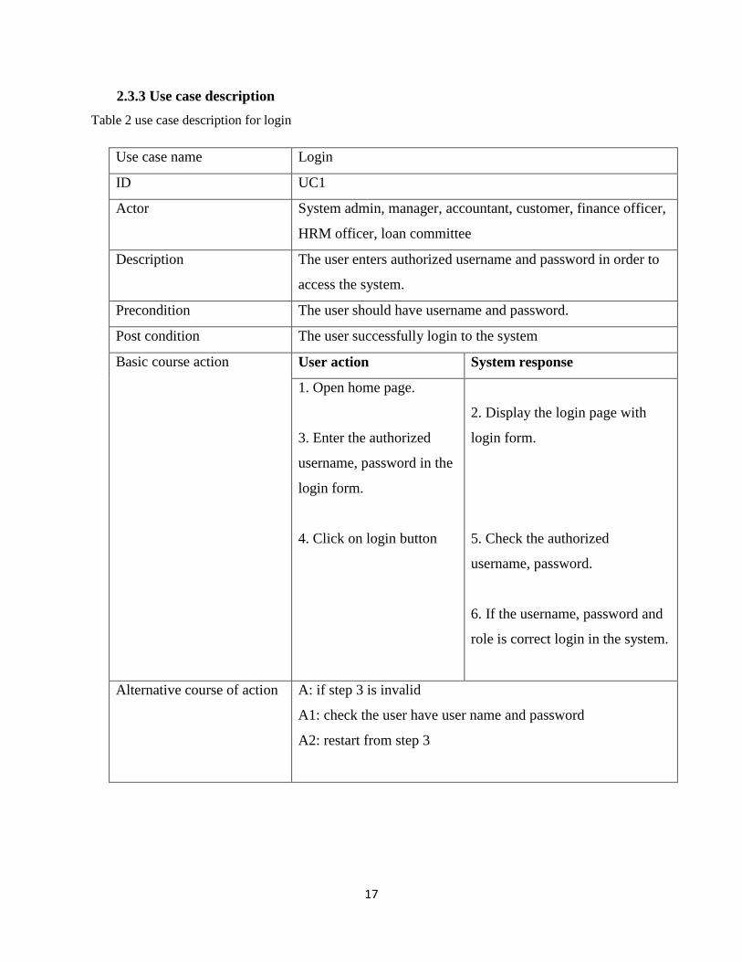
2.3.3 Use case description
Table 2 use case description for login
Use case name Login
ID UC1
Actor System admin, manager, accountant, customer, finance officer,
HRM officer, loan committee
Description The user enters authorized username and password in order to
access the system.
Precondition The user should have username and password.
Post condition The user successfully login to the system
Basic course action User action System response
1. Open home page.
3. Enter the authorized
username, password in the
login form.
4. Click on login button
2. Display the login page with
login form.
5. Check the authorized
username, password.
6. If the username, password and
role is correct login in the system.
Alternative course of action A: if step 3 is invalid
A1: check the user have user name and password
A2: restart from step 3
18
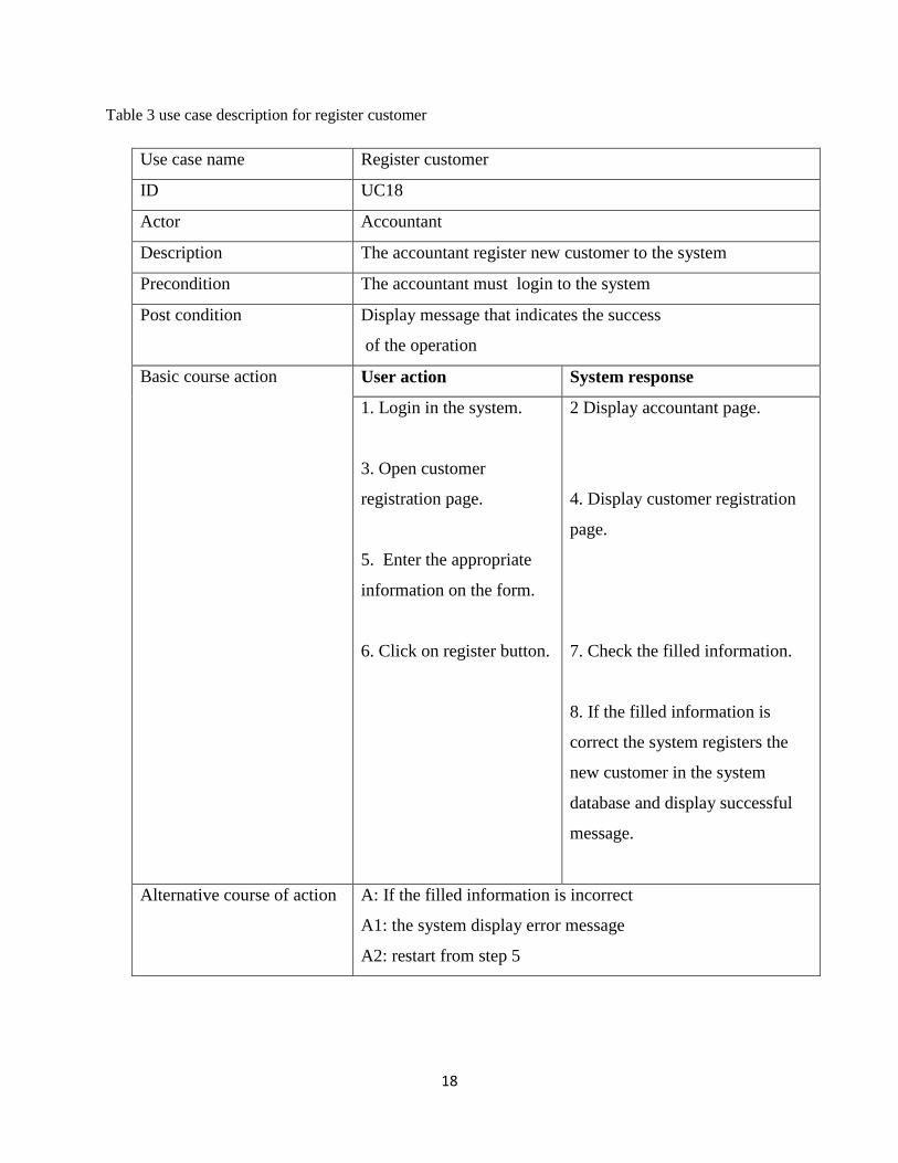
Table 3 use case description for register customer
Use case name Register customer
ID UC18
Actor Accountant
Description The accountant register new customer to the system
Precondition The accountant must login to the system
Post condition Display message that indicates the success
of the operation
Basic course action User action System response
1. Login in the system.
3. Open customer
registration page.
5. Enter the appropriate
information on the form.
6. Click on register button.
2 Display accountant page.
4. Display customer registration
page.
7. Check the filled information.
8. If the filled information is
correct the system registers the
new customer in the system
database and display successful
message.
Alternative course of action A: If the filled information is incorrect
A1: the system display error message
A2: restart from step 5

19
Table 4 use case description for create user account
Use case name Create user account
ID UC4
Actor System administrator
Description The admin creates user name and password for users
Precondition Admin first login to the system
Post condition Successfully create account
Basic course action User action System response
1. login in the system
3. Open the create account
page.
5. Fill use name and
password.
6. Click on create button.
2 Display admin page
4.Display create new account
form
7. Check the filled information on
the form.
8. If the filled information is
correct the system saves on the
system database.
Alternative course of action A: system display ‘’account is not created message’’.
A1: repeat from step4.

20
Table 5 use case description for send loan request
Use case name Send loan request
ID UC37
Actor customer
Description Send request for loan by specifying the amount of money it
requires
Precondition The customer must login to the system
Post condition Successfully send request
Basic course action User action System response
1. first the customer login
to his page
3. Open a page for Loan
Request.
5. Fill the appropriate
information on the form.
7. Click on request button.
2 Display customer page
4. Display Loan Request form.
.
6 Check the filled information on
the form
8. If the filled information is valid
the system displays successful
message.
Alternative course of action A: If the customer did not fulfill the requirement
A1: system display error message
A2: restart from step 4.

21
Table 6 use case description for approve loan request
Use case name Approve loan request
ID UC28
Actor Loan committee
Description Receive customer requests , the system check the conditions
and accept or reject the request
Precondition The loan committee must login to the system
Post condition Successfully see the request
Basic course action User action System response
1. Login in to the system.
3. Open view loan request
page.
5. loan committee click
status button
6. If the request
information is fulfilling the
criteria the system accept
the request.
2 Display the loan committee
page.
4. Display the loans request table.
Alternative course of action A: If the request information is not fulfilling the criteria
A1: the system reject the request

22
Table 7 use case description for view report
Use case name view report
Id Uc17
Actor Accountant, manager
Description View monthly activity in the association
Pre-condition Accountant, manager login to the system
Post condition Display monthly report
Basic course action User action System response
1. login to the system
3. click view report
button
5. Click report button
2.display accountant,
manager page
4. display report button
6. display monthly report
23
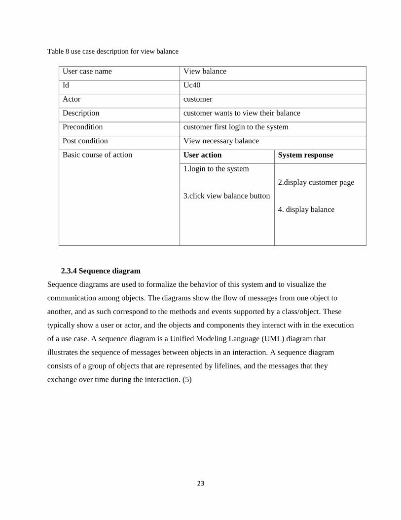
Table 8 use case description for view balance
User case name View balance
Id Uc40
Actor customer
Description customer wants to view their balance
Precondition customer first login to the system
Post condition View necessary balance
Basic course of action User action System response
1.login to the system
3.click view balance button
2.display customer page
4. display balance
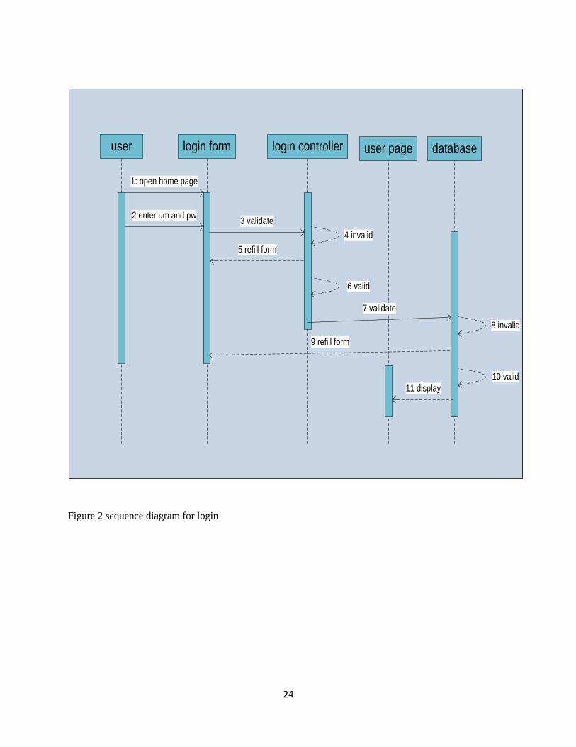
2.3.4 Sequence diagram
Sequence diagrams are used to formalize the behavior of this system and to visualize the
communication among objects. The diagrams show the flow of messages from one object to
another, and as such correspond to the methods and events supported by a class/object. These
typically show a user or actor, and the objects and components they interact with in the execution
of a use case. A sequence diagram is a Unified Modeling Language (UML) diagram that
illustrates the sequence of messages between objects in an interaction. A sequence diagram
consists of a group of objects that are represented by lifelines, and the messages that they
exchange over time during the interaction. (5)
24
user login form login controller databaseuser page
7 validate
5 refill form
2 enter um and pw
9 refill form
1: open home page
8 invalid
4 invalid
3 validate
6 valid
10 valid
11 display
Figure 2 sequence diagram for login

25
accountant login form login controller accountant page register formRegister form
controllerdatabase
1. open home page
2: enter un and pw
6 ckeck
5 refill form 4 invalid
3 ckeck validate
7 invalid8 refill form
11 display page 10 valid
register link
12 click register link
13 fill form 14 validate
16 refill form 15 invalid
18 invalid19 refill form
20 display seccefull message
17 click register buttoncheck
Figure 3 sequence diagram for register customer

26
Admin login form login controller admin pageCreate account
form
Create account
Form controllerdatabase
1. open home page
2: enter un and pw
6 ckeck
5 refill form 4 invalid
3 ckeck validate
7 invalid8 refill form
11 display page 10 valid
Create account
link
12 click create account link
13 fill form 14 validate
16 refill form 15 invalid
17 check
18 invalid19 refill form
20 display seccessful message
valid
Figure 4 sequence diagram for create account

27
customer login form login controller customer pageSend loan
form
Send loan
Form controllerdatabase
1. open home page
2: enter un and pw
6 ckeck
5 refill form 4 invalid
3 ckeck validate
7 invalid8 refill form
11 display page 10 valid
Send loan
link
12 click send loan link
13 fill form14 validate
16 refill form 15 invalid
17 store in DB
18 display seccessful message
valid
Figure 5 sequence diagram for send loan request

28
customer login form login controller Customer page database
1. open home page
2: enter un and pw
6 ckeck
5 refill form
4 invalid
3 ckeck validate
7 invalid8 refill form
11 display page10 valid
View balance
link
12 click view balance link
13 display balance
valid
Figure 6 sequence diagram for view balance

29
2.3.5 Activity diagram
Activity diagram is UML behavior diagram which shows flow of control or object flow with
emphasis on the sequence and conditions of the flow. An activity diagram visually presents a
series of actions or flow of control in a system similar to a flowchart or a data flow diagram. (5)
Activity diagrams are often used in business process modeling
Some of the activity diagrams of the project known as DMU employee’s saving and credit
association information management system are:
Actor open home page
enter uesr name and password
invalid
Actor click login button
display error messagevalid
display actor page check
Figure 7 Activity diagram for login

30
admin open home page
enter user name and password
admin Click login button
invalid
system display error message
valid
system display admin page
Admin click create account link
system display create account form admin fill form and click create account
invalid fillsystem display error message
system display successful message
valid
check
check
Figure 8 Activity diagram for create account

31
Customer open home page
enter username and password
click login button
invalid
the system display error message
valid
Customer click send loan link
System display send loan formCustomer fill form and click send
invalid
the system display invalid message
system display successful message
valid
System display customer page
check
check
Figure 9 Activity diagram for send loan request

32
Customeropen home page
enter username and password
click login button
invalid
the system display error message
valid
Customer click view balance link
System display customer page
system display customer balance
check
Figure 10 Activity diagram for view balance

33
2.3.6 Analysis class diagram
The class diagram in the unified modeling language is a type of static structure diagram that
describes the structure of a system by showing the system's class, their attributes, operations (or
methods), and the relationships among objects.
The class diagram is the main building block of object oriented modeling. Classes in a class
diagram represent both the main elements, interactions in the application, and the classes to be
programmed (5)

34
Figure 11 Analysis class diagram

35
CHAPTER THREE
3. SYSTEM DESIGN
System design is the first part to get into the solution domain in a software development.
The purpose of designing is to show the direction how the system is built and to obtain clear and
enough information needed to drive the actual implementation of the system. It is based on
understanding of the model that the software built on. The objectives of design are to model the
system with high quality. Implementing of high quality system depend on the nature of design
created by the designer.
3.1 Design class diagram
The class diagram represents the static view of an application. Class diagram is not only used for
visualizing, describing and documenting different aspects of a system but also for constructing
executable code of the software application. The class diagram describes the attributes and
operations of a class and also the constraints imposed on the system. The classes diagrams are
widely used in the modeling of object oriented systems because they are only UML diagrams
which can be mapped directly with object oriented languages. The class diagram shows a
collection of classes, interfaces, associations, collaborations and constraints. It is also known as a
structural diagram for this the team developed the following class diagram.

36
Figure 12 design class diagram

37
3.2. Class diagram description
Table 7 description of customer class
Customer class attribute
Attribute purpose Type
Account no To uniquely identify the customer varchar
Fname To represent the first name of the customer varchar
mname To represent the father name of the customer varchar
lanme To represent the grandfather name of the customer varchar
Sex To identify the customer’s gender varchar
Age To represent how old the customer is int
photo To represent the photo graff of the customer longtext
customerid To represent university id varchar
Deposit amount To represent monthly deposit amount float
Share amount To represent amount of share to buy at the member float
date To represent customer registration date date
Customer class method
Method Description
Send Used to send request and send feedback
view Used to view response and balance
38
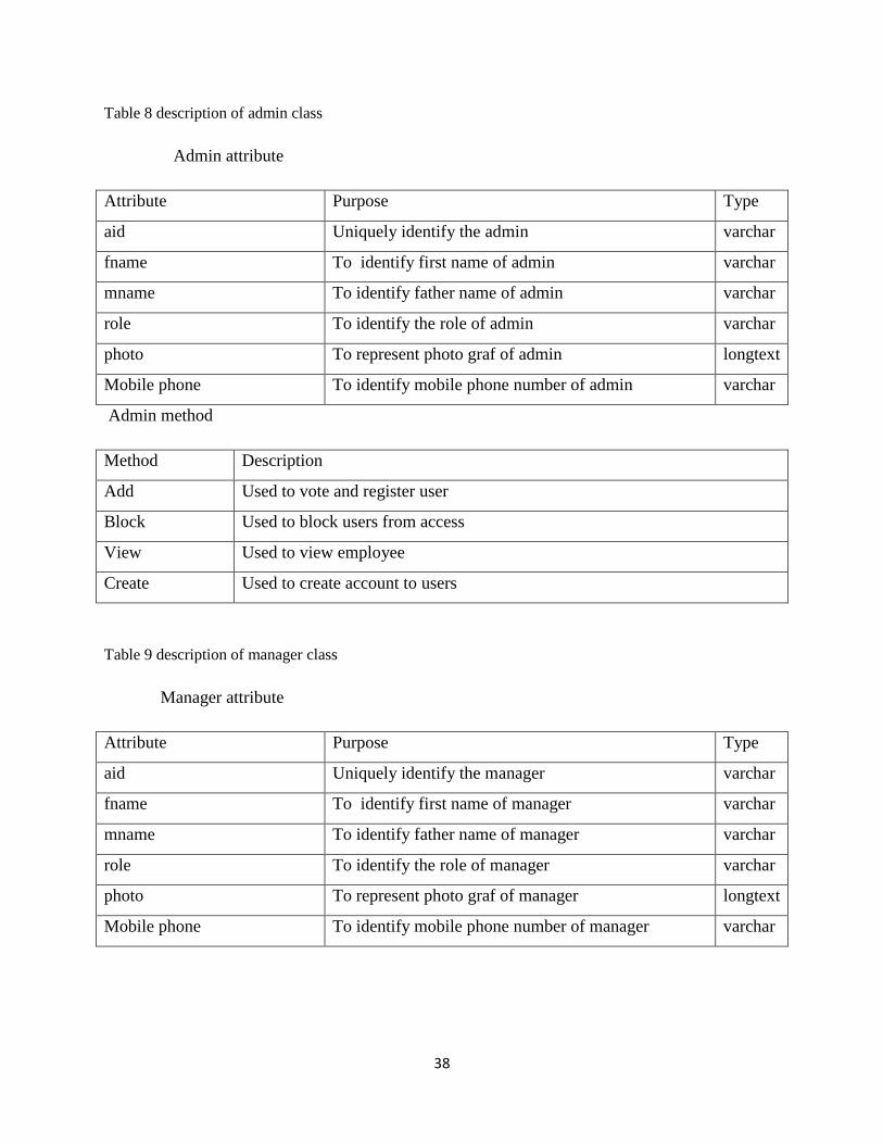
Table 8 description of admin class
Admin attribute
Attribute Purpose Type
aid Uniquely identify the admin varchar
fname To identify first name of admin varchar
mname To identify father name of admin varchar
role To identify the role of admin varchar
photo To represent photo graf of admin longtext
Mobile phone To identify mobile phone number of admin varchar
Admin method
Method Description
Add Used to vote and register user
Block Used to block users from access
View Used to view employee
Create Used to create account to users
Table 9 description of manager class
Manager attribute
Attribute Purpose Type
aid Uniquely identify the manager varchar
fname To identify first name of manager varchar
mname To identify father name of manager varchar
role To identify the role of manager varchar
photo To represent photo graf of manager longtext
Mobile phone To identify mobile phone number of manager varchar
39
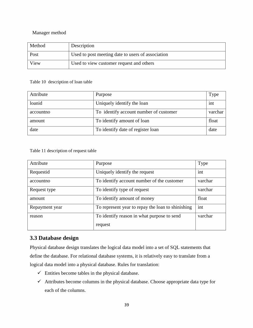
Manager method
Method Description
Post Used to post meeting date to users of association
View Used to view customer request and others
Table 10 description of loan table
Attribute Purpose Type
loanid Uniquely identify the loan int
accountno To identify account number of customer varchar
amount To identify amount of loan float
date To identify date of register loan date
Table 11 description of request table
Attribute Purpose Type
Requestid Uniquely identify the request int
accountno To identify account number of the customer varchar
Request type To identify type of request varchar
amount To identify amount of money float
Repayment year To represent year to repay the loan to shinishing int
reason To identify reason in what purpose to send
request
varchar
3.3 Database design
Physical database design translates the logical data model into a set of SQL statements that
define the database. For relational database systems, it is relatively easy to translate from a
logical data model into a physical database. Rules for translation:
Entities become tables in the physical database.
Attributes become columns in the physical database. Choose appropriate data type for
each of the columns.

40
Unique identifiers are not allowed to have NULL values. These referred to as primary
keys in the physical database. Consider creating a unique index on the identifiers to
enforce uniqueness.
Relationships are module as foreign keys
3.3.1Physical data model
A physical database model shows all table structures, including column name, column data type,
column constraints, primary key, foreign key, and relationships between tables. Features of a
physical data model include: Specification all tables and columns. Foreign keys are used to
identify relationships between tables.
Table 12 employee table
41
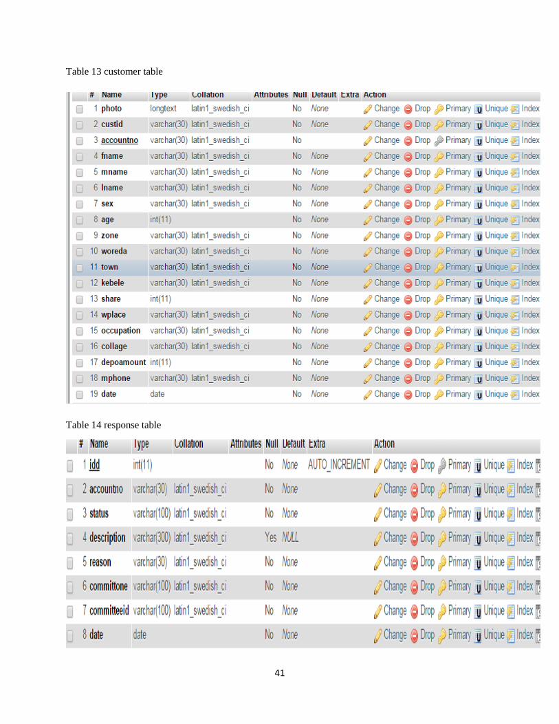
Table 13 customer table
Table 14 response table

42
Table 15 meeting table
Table 16 feedback table
3.4 User interface design
User Interface (UI) Design focuses on anticipating what users might need to do and ensuring that
the interface has elements that are easy to access, understand, and use to facilitate those actions.
UI brings together concepts from interaction design, visual design, and information architecture.

43
Figure 13 login page

44
Figure 14 admin page create account

45
Figure 15 register customer
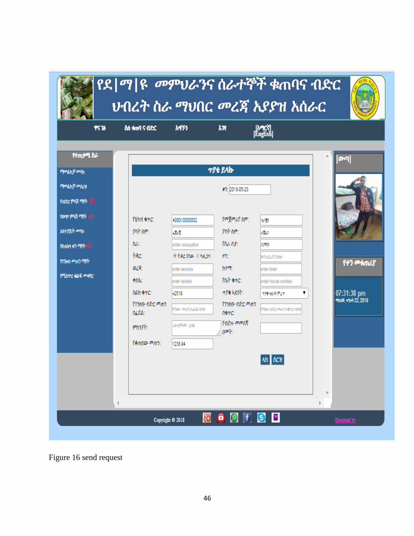
46
Figure 16 send request

47
3.5 System architecture (deployment design)
A UML deployment diagram depicts a static view of the run time configuration of hardware
nodes and the software components that run on those nodes. UML deployment diagrams show
the hardware for your system, the software that is installed on that hardware, and the middleware
used to connect the disparate machines to one another (5)
Figure 17 deployment design
48
CHAPTER FOUR
4 IMPLEMENTATION
4.1. Over view of the programming language used
This project used php server side programming technology integrated mysqli database with a
programming language. Because:
The code and its syntax is simple to understand
There is a wealth of online information regarding PHP
It's quick to develop in PHP
PHP is flexible.
It's available for free
It runs on many different operating system easy to access other web based tools through PHP
(i.e. Google)
In general PHP is a widely used open source general purpose scripting language that is especially
suited for web development and can be embedded into HTML.
4.2 Algorithm used
Register customer
Click on register customer link
Registration form is displayed
Fill user profile data
Click on register button
If (valid)
Display successful message.
Else display invalid input message
create account
Click on create account link
Form is displayed
Fill information for the user
Click on create button

49
If (valid)
Display successful message.
Else display invalid input message
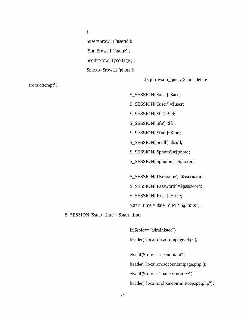
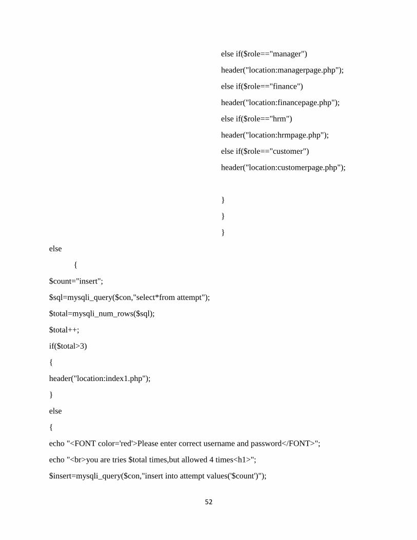
4.3 sample code
Sample code for login
<html>
<head>
<script>
function show_password() {
var x = document.getElementById("password");
if (x.type === "password") {
x.type = "text";
}
else {
x.type = "password";
}
}
</script>
</head>
<body>
<?php
session_start();
include("connection.php");
?>
<?php

50
if(isset($_POST["login"]))
{
if($con)
{
$un=$_POST["username"];
$password=$_POST["Password"];
$pw=md5($_POST["Password"]);
$sql="select * from account where username='$un' and
password='$pw' and status='Active'";
$matchfound=mysqli_query($con,$sql);
if($row=mysqli_fetch_assoc($matchfound))
{
$id=$row['userid'];
$username=$row['username'];
$password=$row['password'];
$role=$row["role"];
$sql1="select * from customer where accountno='$id' ";
$matchfound1=mysqli_query($con,$sql1);
$row1=mysqli_fetch_assoc($matchfound1);
{
$acc=$row1['accountno'];
$fnn=$row1['fname'];
$photoo=$row1['photo'];
$sql1="select * from employee where userid='$id' ";
$matchfound1=mysqli_query($con,$sql1);
$row11=mysqli_fetch_assoc($matchfound1);
51
{
$user=$row11['userid'];
$fn=$row11['fname'];
$coll=$row11['collage'];
$photo=$row11['photo'];
$sql=mysqli_query($con,"delete
from attempt");
$_SESSION['$acc']=$acc;
$_SESSION['$user']=$user;
$_SESSION['$id']=$id;
$_SESSION['$fn']=$fn;
$_SESSION['$fnn']=$fnn;
$_SESSION['$coll']=$coll;
$_SESSION['$photo']=$photo;
$_SESSION['$photoo']=$photoo;
$_SESSION['Username']=$username;
$_SESSION['Password']=$password;
$_SESSION['Role']=$role;
$start_time = date("d M Y @ h:i:s");
$_SESSION['$start_time']=$start_time;
if($role=="administor")
header("location:adminpage.php");
else if($role=="accountant")
header("location:accountantpage.php");
else if($role=="loancommittee")
header("location:loancommitteepage.php");
52
else if($role=="manager")
header("location:managerpage.php");
else if($role=="finance")
header("location:financepage.php");
else if($role=="hrm")
header("location:hrmpage.php");
else if($role=="customer")
header("location:customerpage.php");
}
}
}
else
{
$count="insert";
$sql=mysqli_query($con,"select*from attempt");
$total=mysqli_num_rows($sql);
$total++;
if($total>3)
{
header("location:index1.php");
}
else
{
echo "<FONT color='red'>Please enter correct username and password</FONT>";
echo "<br>you are tries $total times,but allowed 4 times<h1>";
$insert=mysqli_query($con,"insert into attempt values('$count')");

53
}
}
}
else
echo "Connection Failed";
}
?>
<table width="100%">
<tr>
<td>
<table border="" width="100%">
<tr><td bgcolor="#808080" style="font-size: 20px">
<h2 align="center">User Login</h2></td></tr><tr
style="width:100%"><td bgcolor="#1f618d">
<form action="" method="POST" enctype="multipart/form-data">
<h3 style="background:#1f618d;height:30px "align="center">User Name:</h3> <input
type="text" name="username" placeholder="Enter User Name" required="user name is
required" style="height: 35px;width: 100%"><br>
<h3 style="background:#1f618d;height:30px "align="center">Password:</h3> <input
type="password" name="Password"id="password" placeholder="Enter Password"
required="password is required" style="height: 35px;width: 100%"><br><br>
<label >
<input type="checkbox" name="checkbox"
id="chekbox" onClick="show_password();">Show Password
</label>
<input type="submit" name="login"value="Login"style="font-size: 20px;background:
#808080;color: white">
<input type="reset" value="Clear"style="font-size: 20px;background: #808080;color:
white"><br><br>
<a href="forgotpass.php" ><span >Forgot password?</a></h3></span>

54
</form>
</td></tr>
</table>
<?php
//}
?>
</td>
</tr>
</table>
</body>
</html>

55
CHAPTER FIVE
5 CONCLUSION AND RECOMMENDATION
5.1 Conclusion
This project is developed for DMU employee’s saving and credit association to web based
system in order to give efficient, reliable, timely, secure system, easily accessed, availability
of service throughout Debre markos university .The main propose of this system is not only for
the user but also for the association.
By challenges money problems we develop this new system, this system is very important for
developing Debremarkos university saving and credit association. In this project we tried to
solving complex and manual system to web based mechanism by using this new system such as:
substitute manual to web based system.
The proposed system made computerized to reduce human errors and to increase the efficiency.
The main aim of our project is:
Reduce the number of employee
Minimize the time required to perform task
Minimize the work load of employees
Remove redundancy of data
Update the record easily
Easy retrieval of data
Provide sufficient security
Increase employee satisfaction etc.
5.2 Recommendation and future enhancement
Any user who wants to interact with DMU employee saving and credit association should
have some knowledge. In order to clarify who required what knowledge the team
Recommended:-
Related with customer
User must have a basic firsthand experience with systems or other related
experiences.
User must have a basic knowledge of computer.
Training user should be considering for best performance and efficiency of IT
technology.
Related with association

56
Organization should have adequate computer facilities to the activities of student
information system.
Budget should be allocated to take specific measure: -
To change the manual system into new system.
To maintain the system in a timely and speedy manner.
Future enhancement
Online payment
Profit distribution for share
Procurement

57
Reference
(1) (Unpublished) Debre markos university employee's saving and credit association rule and
regulation, 2007
(2) definition of system requirement spacification
https://www.inflectra.com/ideas/topic/requirements-definition.aspx , accessed december 3 2010
1:30:23 AM
(3) Functional requirement vs nonfunctional requirement www.google.com/ , accessed
December 5 2010 2:23:12 AM
(4) UML use case diagram https://www.smartdraw.com/use-case-diagram/ accessed december
10 2010 3:04:45AM
(5) UML diagram, https://www.tutorialspoint.com/uml/uml_class_diagram.htm accessed
December 15 2010 1:21:03AM