division 22 plumbing 22 0513- common motor...
TRANSCRIPT

UNIVERSITY OF NORTH DAKOTA – DESIGN STANDARDS page 1
Print Date: 11/4/2016 DIVISION 22 – PLUMBING R:\DesignStandards\Current Design Standards\Full Design Standards Documents-Drafts\Division 22 - Plumbing
DIVISION 22 – PLUMBING
22 0513- COMMON MOTOR REQUIREMENTS FOR PLUMBING
22 0515- EXPANSION FITTINGS AND LOOPS FOR PLUMBING EQUIPMENT
22 0519 METERS AND GAGES FOR PLUMBING
A. UND will purchase and install all meters. The project manager shall contact UND Facilities
to install all utility meters, both temporary and permanent. The temp meter shall remain
active for the entire project. There shall be no more than 24 hours between the removal of
the temporary meter and installation of the permanent meter.
Badger Meter Inc. (BMI) Model 250B (.5” to 1.5”) and Model 228B (2” or 2.5”) (hot
water condensate meters) (To be used with new or Billable Accounts)
Installation
1. The installation site should be located in a position where the meter is easily
accessible for reading, maintenance and installation.
2. The Badger Meter Inc. meters must be mounted horizontally or upstream vertically.
3. For accurate measurement, the meter must have a straight undisturbed pipe with
length of ten (10) pipe diameters upstream and five (5) pipe diameters
downstream. If this is not possible, straightening vanes may have to be used.
4. Each meter shall be installed with a check valve in order to prevent backflow.
5. Each meter shall be piped in a fashion that the pipe will be 100% full when
condensate flow occurs.
6. Each meter shall be sized properly based on flow and velocity as shown in the
following chart.
7. Each meter shall be installed with a Badger Meter Inc. Model 320 Flow Transmitter.
The model 320 shall be wired to the building Electro Industry Gauge electrical meter.
The Model 320 switch shall be configured for one pulse per 10 gallons.
Specifications
Model 250B and 228B

UNIVERSITY OF NORTH DAKOTA – DESIGN STANDARDS page 2
Print Date: 11/4/2016 DIVISION 22 – PLUMBING R:\DesignStandards\Current Design Standards\Full Design Standards Documents-Drafts\Division 22 - Plumbing
When connecting to the EIG unit, you need:
Qty. 1 ea.
Badger Meter Inc. Model 250B or 228B
Badger Model Inc. Model 320
A1026 Power Supply
The application you have already installed would include:
Qty. 1 ea.
Badger Meter Inc. Model 250B or 228B
Badger Meter Inc. Model 320
A1026 Power Supply
350T RF transmitter
WMM Water Meter Monitor
If you want to read the meter via wireless and plug it into the EIG:
Qty. 1 ea.
Badger Meter Inc. Model 250B or 228B
Badger Meter Inc. Model 320
A1026 Power Supply
350T RF transmitter
WMM Water Meter Monitor
350R RF receiver which will provide additional output for the EIG
NIAGARA Series MTX (hot water condensate meter) (Existing or Non-billable accounts)
Model 421
Installation
8. The installation site should be located in a position where the meter is easily
accessible for reading, maintenance and installation.
9. The Niagara MTX meter must be mounted horizontally with the register on top. 10.
For accurate measurement, the meter must have a straight undisturbed pipe with
length of five (5) pipe diameters upstream and three (3) pipe diameters
downstream. If this is not possible, straightening vanes may have to be used.
11. Each meter shall be installed with a check valve in order to prevent backflow.
12. Each meter shall be piped in a fashion that the pipe will be 100% full when
condensate flow occurs.
13. Each meter shall be sized properly based on flow and velocity as shown in the
following chart.
14. Each meter shall be installed with a Niagra Model 840 switch. The model 840
switch shall be wired to the building Electro Industry Gauge (EIG) electrical

UNIVERSITY OF NORTH DAKOTA – DESIGN STANDARDS page 3
Print Date: 11/4/2016 DIVISION 22 – PLUMBING R:\DesignStandards\Current Design Standards\Full Design Standards Documents-Drafts\Division 22 - Plumbing
meter. The model 840 switch shall be configured for one pulse per 100 gallons.
Specifications
Model 421 (Hot)
1. UND Steam Service & Condensate Meter Procedure
The purpose of this procedure is to maintain standards for metering of UND steam
services and steam condensate returned to the steam distribution system. The
standards set forth in this procedure shall be enforced with new construction, existing
buildings, and maintenance of steam and steam condensate metering systems.
New Construction:
Temporary Metering:
Prior to construction the project manager shall request a steam service to the construction site
through UND Facilities Utility Accountant. A fund number or Org number will be required by
UND Facilities Utility Accountant at this time. The UND plumbers shall provide and size the
temporary meter. The temporary meter will be provided by UND at no cost project. The
temporary meter shall be installed by UND Plumbers. The meter and steam installation shall be
inspected and approved by the UND Plumbing Department before the steam is turned on. The
temporary meter shall be read by UND Facilities Utility Accountant. The Utility Accountant
shall be notified when the meter is to be removed from service by the project manager.
At no time will dumping of steam condensate or venting steam to atmosphere be allowed.
Billing penalties may be applied to the project and/or contractor if necessary.
Permanent Metering:
The permanent condensate metering shall be sized and installed based on UND steam condensate
standards and the engineer on record for the construction project. The meter shall be provided by
the construction project. All condensate meters shall be connected to
UND’s automated meter reading system under the construction contract. All equipment and
wiring necessary to connect to UND’s automated meter reading system will be provided by the

UNIVERSITY OF NORTH DAKOTA – DESIGN STANDARDS page 4
Print Date: 11/4/2016 DIVISION 22 – PLUMBING R:\DesignStandards\Current Design Standards\Full Design Standards Documents-Drafts\Division 22 - Plumbing
construction contract. All condensate leaving the facility shall be metered. Once the steam
condensate meter is installed UND Facilities Utility Accountant shall be notified by the
plumbers. The Utility Accountant shall then inventory and tag the meter. The permanent meter
shall be read monthly by the UND Facilities Utility Accountant.
At no time will dumping of steam condensate or venting steam to atmosphere be allowed.
Billing penalties may be applied if necessary.
Existing Buildings:
The permanent condensate metering for each building shall be sized and installed based on UND
steam condensate standards. The condensate meter shall be maintained in accordance with UND
condensate meter maintenance procedures. The UND Plumbing Department shall be responsible
for meter installation and maintenance. If provisions are available, the condensate meter shall be
connected to UND’s automated meter reading system.
The Utility Accountant shall be responsible for inventory and tagging of the meter. The meter
shall be read monthly by the UND Facilities Utility Accountant.
At no time will dumping of steam condensate or venting steam to atmosphere be allowed. In the
event condensate must be dumped for emergency of maintenance purposes, the Communications
Center shall be notified when dumping of the condensate began and when dumping of the
condensate halted. The communications center shall also notify the UND Steam Plant and UND
utility accountant.
Steam Customers:
The permanent condensate metering for each steam customer shall be sized and installed based
on UND steam condensate standards. The condensate meter shall be maintained in accordance
with UND condensate meter maintenance procedures. The UND Plumbing Department shall be
responsible for meter installation and maintenance. If provisions are available, the condensate
meter shall be connected to UND’s automated meter reading system.
The Utility Accountant shall be responsible for inventory and tagging of the meter. The meter
shall be read monthly by the UND Facilities Utility Accountant.
Dumping of steam condensate or venting steam to atmosphere is not allowed. Billing penalties
may be applied if necessary. In the event condensate must be dumped for emergency of
maintenance purposes, the Communications Center shall be notified when dumping of the
condensate began and when dumping of the condensate halted. The communications center shall
also notify the UND Steam Plant and UND utility accountant.
An annual inspection of each billable meter shall be conduction by UND Facility
Plumbing department to determine condition of metering, piping, and maintenance needs. The
UND Facilities PM system shall generate the work order for each annual inspection.

UNIVERSITY OF NORTH DAKOTA – DESIGN STANDARDS page 5
Print Date: 11/4/2016 DIVISION 22 – PLUMBING R:\DesignStandards\Current Design Standards\Full Design Standards Documents-Drafts\Division 22 - Plumbing
Meter Size and Installation Requirements:
The meter size and type shall be determined by UND Plumbing department or the engineer on
record for a project. Each Condensate meter shall have a local register and must have an
electrical contact output that will pulse each 10 or 100 gallons. The contact output shall be
connected to the UND automated meter reading system.
See “Condensate Meter Policy Exhibit A” for approved meter types, sizes, and
installation instructions.
Meter Maintenance:
Condensate meter maintenance shall be performed by request of a work order. All condensate
meter maintenance labor and material shall be charged to steam line distribution.
A work order may be requested by maintenance personnel, UND Utility Accountant, Steam
Customer, building occupant, etc. A work order may be generated for but not limited to, the
following reasons:
Non-working meter
Meter suspected not to be accurate
Leaking condensate
Bad check valve
Improper piping
Testing and calibration
When a condensate meter is scheduled for maintenance, under no circumstances shall the meter
be serviced in the field. When maintenance is conducted, the existing condensate meter will be
removed from service. A new or refurbished; tested and certified condensate meter shall be
installed and placed in service. The Facilities Department “Meter Change-out Form” shall be
used in this process. The completed “Meter Change out Form” shall be forwarded to the UND
Utility accountant.
The condensate meter removed from service shall be taken back to the Plumbers test station for
repair, calibration, testing, and certification. Once the meter is tested and certified the meter can
then be placed in inventory for use at a later date. If the meter cannot be repaired or certified, it
shall be discarded.
Meter Tagging and Inventory:
A condensate meter inspection and inventory will be conducted in each University of
North Dakota building and each steam customer’s building. The purpose of this
procedure is to develop a comprehensive inventory of steam services, condensate meters, number
of meters in each building, location of each meter, and identify areas that are not metered
(whether a portion of a facility or the facility in whole). The number of condensate meters should
equal the number of steam services. The objective of the inspection of the meter assembly is to

UNIVERSITY OF NORTH DAKOTA – DESIGN STANDARDS page 6
Print Date: 11/4/2016 DIVISION 22 – PLUMBING R:\DesignStandards\Current Design Standards\Full Design Standards Documents-Drafts\Division 22 - Plumbing
determine condition and type of condensate meter, size of meter, condition and proper
configuration of piping, and velocity of condensate during discharge of condensate pump.
During the inspection process each condensate meter shall be tagged with a unique meter
number. The unique meter number will be assigned to each meter by the “facilities utility
accountant”. The “facilities utility accountant” will be responsible for maintaining the
“condensate meter inventory” database.
At a minimum, but not limited to; the following information will be collected by the plumbers
at each meter location:
1. Building Name
2. Building Number
3. Room Number
4. Steam Service/Meter location
5. Meter Manufacture
6. Meter Model Number
7. Meter Size
8. Meter rated minimum flow rate
9. Meter maximum flow rate
10. Meter serial or meter Number
11. Meter Integrator type: (Gallons – Pounds)
12. Meter Integrator Multiplier
13. Remote Integrator manufacture
14. Remote Integrator Model Number
15. Remote Integrator Location
16. Remote Integrator type: (Gallons – Pounds)
17. Remote Integrator multiplier
18. Proper piping (yes/no)
19. Proper and working back flow prevention
20. Measured condensate velocity (FPS)
21. Other
22. Comments
Responsibilities:
UND Plumbers will be responsible for inspection and collecting meter data at each meter site.
Plumbers will be responsible for entering data for each meter on each inspection form.
The Facilities utility accountant will be responsible for provision and collection of inspection
forms. The Facilities utility accountant will be responsible for data entry into the database for the
“Condensate Meter Inventory”
Technology Advancement Coordinator will be responsible for review of the compiled data from
the inspection and inventory process. From the review it will be determined if the proper type of
meter and size of meter is installed in each location.

UNIVERSITY OF NORTH DAKOTA – DESIGN STANDARDS page 7
Print Date: 11/4/2016 DIVISION 22 – PLUMBING R:\DesignStandards\Current Design Standards\Full Design Standards Documents-Drafts\Division 22 - Plumbing
Demarcation line for building versus steam line distribution:
Below is a chart that displays a separation line showing responsibilities for maintenance and
billing purposes. Everything right of the demarcation line should be considered part of the steam
distribution system; condensate pump, venting, check valve, condensate meter, etc. Everything
before the condensate pump or left of the demarcation line will be the building responsibility
and/or the steam customer responsibility.
Chart showing the demarcation line for steam condensate distribution
Chart showing the demarcation line for steam distribution

UNIVERSITY OF NORTH DAKOTA – DESIGN STANDARDS page 8
Print Date: 11/4/2016 DIVISION 22 – PLUMBING R:\DesignStandards\Current Design Standards\Full Design Standards Documents-Drafts\Division 22 - Plumbing
GENERIC SPECIFICATION FOR HIGH PERFORMANCE POWER MONITORING, REVENUE METERING,
POWER QUALITY RECORDING, AND RTU FUNCTIONALITY
LP Steam
Gate Valve
Steam Trap
Condensate
Demarcation line for
steam distribution
LP Steam
Steam Distribution System
LP Steam to Building Customer
Building Customer Responsibility
Condensate
Nexus® 1252 Meter
3. PRODUCT
3.1 Power Meters
A. Power meter shall be multi-function 3 phase solid state unit with ability to connect to
either 3 phase, 4 wire wye or 3 phase, 3 wire delta circuits.

UNIVERSITY OF NORTH DAKOTA – DESIGN STANDARDS page 9
Print Date: 11/4/2016 DIVISION 22 – PLUMBING R:\DesignStandards\Current Design Standards\Full Design Standards Documents-Drafts\Division 22 - Plumbing
B. Power meter shall include two 10-character, alphanumeric passwords, which shall
protect the unit from unauthorized tampering.
C. Voltage and current inputs to the meter shall conform to the following at a minimum:
1. Monitor shall accept input of four (4) independent voltage inputs and four
(4) independent current inputs of the stated capacity.
2. Voltage input shall be 120 volts AC with available option for direct
connection to voltage circuits of up to 600 VAC without the use of
potential transformers.
3. Voltage input shall be optically isolated to 2500 volts DC. Shall meet or
exceed ANSI C37.90.1 (Surge Withstand Capability)
4. Current input shall be rated for 5 amps with inputs 2x continuous
programmable to any CT range.
5. Current inputs shall be solid U-Bolt stud inputs with a 10 second over-
current rating of 100 amps and a 1-second over-current rating of 300
amps.
D. Power meter shall measure and report the following quantities at a minimum:
1. Voltage, both phase to neutral and phase to phase, for all three phases;
Auxiliary voltage; Phase angles for each voltage relative to each other.
One cycle, 50 milliseconds and one second readings shall be available
simultaneously.
2. Current, phase A, B, C, N-measured, and N-calculated; Phase angles for
each current relative to voltages. One cycle, 50 milliseconds and one
second readings shall be available simultaneously.
3. Watts (total and per phase), VARs (total and per phase), VA (total and per
phase), Power Factor (total and per phase) and Frequency. 50 milliseconds
and one second readings shall be available simultaneously.
4. Accumulated Watt-hr, VA-hr, and VAR-hr; Watt-hr received; Watt-hr
delivered. VAR-hr and VA-hr reading shall be stored in each of the 4
quadrants of power.
5. Power demand shall be calculated using four (4) different averaging
methods: Thermal Average, Fixed Window Average, Sliding Window
Average, and Predicted Average. Values for all averaging intervals must
be available simultaneously.
6. Power meter shall provide updates of all voltage and current readings at
intervals of 1 cycle, 50 milliseconds, and 1 second. Readings shall be
available for both metering and control. All specified readings shall be
made available via the RS485 ports.
7. Power meter shall provide time-stamped maximum and minimum readings
for every measured parameter.
8. Power meter shall provide coincident VAR readings for all maximum
Watt readings.
E. Power meter shall provide the following accuracies:
1. Voltage accuracy shall be within less than 0.05% for the 1 second readings
and less than 0.1% for the 200 millisecond readings.
2. Current accuracy shall be within less than 0.025% for the 1 second
readings and less than 0.1% for the 200 millisecond readings.

UNIVERSITY OF NORTH DAKOTA – DESIGN STANDARDS page 10
Print Date: 11/4/2016 DIVISION 22 – PLUMBING R:\DesignStandards\Current Design Standards\Full Design Standards Documents-Drafts\Division 22 - Plumbing
3. Power and energy accuracy shall be within less than 0.06% at unity PF
and within 0.10% at 0.50 PF.
4. Frequency accuracy shall be within less than 0.01 Hz for the 1 second
readings and less than 0.03Hz for the 200 millisecond reading.
5. The unit shall have an auto-calibration circuit designed to calibrate the
readings using an internal reference. The calibration shall commence
upon temperature change.
F. Auto-calibration components:
1. 8 Channel sample/hold, for each at the voltage and current channels.
2. Precision internal references with real-time auto calibration for voltage
and current channels.
3. The voltage inputs shall be optically isolated to 2500 volts.
4. Dual 16 bit A/D converters.
G. Power meter shall provide multiple digital communication ports and support
multiple open protocols.
1. Meter shall include four (4) independent, digital communication ports.
Each port shall be RS485 architecture. Port 1 shall be user selectable as
either RS232 or RS485 architecture.
2. Each port shall be user configurable with regard to speed, protocol,
address, and other communications parameters. All ports shall support a
maximum communication speed of 115k baud simultaneously.
3. Meter shall have an Ethernet port as an available option.
4. Meter shall have an internal modem as an available option.
H. Meter shall offer both Modbus and DNP 3.0 level 2 plus, open protocols as
standard configurations. All instantaneous data, logged data, event data, power
quality analysis and waveform information shall be available using these open
protocols.
1. Up to 136 measurements shall be able to be mapped to DNP Static points in
the customizable DNP Point map.
2. Up to 16 relays and 8 resets shall be controlled through DNP.
3. Meter shall be able to hold 250 events of combinations, of four events that
are shall be binary input change, frozen counter, counter change, analog
change.
4. Flexible combinations of 4 events such as binary input change, frozen
counter, counter change, and analog change shall be available for up to 250
events.
5. Meter shall allow freeze commands.
6. Third party certification shall be available.
I. Power meter shall enable users to perform Flicker analysis and shall comply with
the Flicker requirements of EN50160.
1. The unit shall provide users with logging and monitoring for instantaneous
Short term readings (PST-10min) and Long term readings (PLT-4 hour).
2. The meter shall be able to log Flicker readings.
3. Flicker shall be available for both 50Hz and 60Hz systems.
J. The ability to view interharmonics, the discrete frequencies that lie between the
harmonics of the power frequency voltage and current, shall be available.

UNIVERSITY OF NORTH DAKOTA – DESIGN STANDARDS page 11
Print Date: 11/4/2016 DIVISION 22 – PLUMBING R:\DesignStandards\Current Design Standards\Full Design Standards Documents-Drafts\Division 22 - Plumbing
1. Frequencies shall be able to be observed, which are not an integer multiple of
the fundamental and shall be able to appear as discrete frequencies or as a
wide-band spectrum.
2. User shall be able to set a starting point anywhere in the waveform, assuming
there will be enough sample points available after the starting point.
K. Power meter shall provide sequence of events capture and recording.
1. Meter shall have at least eight high-speed status inputs for capturing
external events.
2. All high-speed status inputs shall be monitored at a user set rate from 1 to
8 samples per millisecond.
3. All changes in status shall be time stamped to the nearest millisecond and
placed in an event log with time and event label information.
4. Event log shall enable users to recreate sequence of events involving
external status points.
5. High-speed status inputs shall be able to trigger waveform recording to the
waveform log.
6. Status inputs shall be configurable for event monitoring, pulse
accumulation, or pulse synchronizing.
L. Power meter shall provide a separate IRIG-B input for time synchronizing to GPS
time signal.
1. IRIG-B input shall accept un-modulated time signal input from a standard
GPS satellite clock.
2. Time input shall enable time synchronizing to one millisecond and shall
not be subject to network or other delays.
M. Power meter shall provide an external display to accommodate access to readings
locally and/or remotely.
1. Display shall be a three line, LED format, P40N touch screen display, or a
LCD format, P60N touch screen display.
2. The meter shall be capable of providing readings to a P40N, P41N, and
P43N series of LED displays simultaneously.
3. LED displays shall be 0.56-inch size and display shall include 10-character
alphanumeric segment to provide legend and scaling information for
displayed values. The LED display shall use one communication port.
4. LCD displays shall be large 320 x 240 pixel displays and shall provide
real-time readings, harmonics, waveforms and phasors from power
monitors. The LCD display shall be able to display up to 8 meters per
display.
4. Display shall connect to Power Meter via RS485 communications
architecture. The communication channel shall be isolated at the display to
avoid the introduction of noise.
5. Display shall be able to be powered directly from Power Meter or from an
auxiliary power supply.
6. Display shall communicate with Power Meter using Modbus protocol.
7. Display must be capable of operating over common communications
UNIVERSITY OF NORTH DAKOTA – DESIGN STANDARDS page 12
Print Date: 11/4/2016 DIVISION 22 – PLUMBING R:\DesignStandards\Current Design Standards\Full Design Standards Documents-Drafts\Division 22 - Plumbing
channels. It shall be capable of being connected up to 5,000 feet from the
Power Meter.
8. Display shall be surface mounted for ease of installation.
N. Power meter shall be equipped with non-volatile RAM for recording logs and
programming information.
1. Memory options of Standard and Advanced shall be available.
2. Meter shall store historical trending data, power quality data, and
waveform recordings in memory.
3. Memory shall be allocated to the various logging functions required. All
logging features required shall be simultaneously available at the specified
levels. Exercising any one feature at the specified level shall not limit
exercising of any or all other features to their full, specified level.
4. Meter shall store all programming and set-up parameters in non-volatile
memory. In the event of loss of control power, meter programming data
stored in memory shall be retained for at least 10 years.
O. When supplied with appropriate memory option, power meter shall provide
historical data logging for trending of measured values.
1. Power meter shall contain two independent data logs.
2. Each historical log shall be user configurable. User may select measured
quantities and reading intervals for each log.
3. Each historical log shall record at least 170 days of data where 5 readings
are being stored every 15 minutes.
4. One of the historical logs shall be configurable for time of use recording.
P. The monitor shall internally record and store Time of Use.
1. The following Time of Use parameters must be included:
a. Twenty-year calendar
b. Four seasons
c. Twelve Holidays per season
d. Four TOU schedules per season
e. Eight tariff registers
2. The meter must display the following information in real-time when the
TOU is enabled:
a. Current month accumulations
b. Previous month accumulations
c. Current season accumulations
d. Previous season accumulations
e. Total accumulations to date
3. Full four quadrant accumulations for Watt-hr, VAR-hr, VA-hr and
coincident VARs during peak watt demand including max demand, shall
be available for each tariff schedule, each season and for total
accumulations.
Q. When supplied with appropriate memory option, power meter shall provide
extensive power quality monitoring capability.

UNIVERSITY OF NORTH DAKOTA – DESIGN STANDARDS page 13
Print Date: 11/4/2016 DIVISION 22 – PLUMBING R:\DesignStandards\Current Design Standards\Full Design Standards Documents-Drafts\Division 22 - Plumbing
1. Power meter shall measure and record the magnitude and phase angle of
all real time harmonics through the 128th for all voltages and currents.
Meter shall provide %THD and K-Factor for all channels.
2. All harmonic magnitude values shall be available through the digital
communications ports in real time.
3. Power meter shall capture and record all ITIC/CBEMA quality events.
4. ITIC/CBEMA events shall be date/time stamped to the millisecond.
Entries to CBEMA log shall include date/time stamp, duration, and
magnitude information. The CBEMA log shall be downloadable through
the digital communications ports.
5. The CBEMA log shall hold over 1024 events in a revolving FIFO format.
6. Power meter shall capture and record out-of-limit conditions in a log.
Entries to Limits log shall be made anytime a monitored quantity exceeds
the user set limit assigned to that quantity.
7. Entries to the Limits log shall be time stamped to the millisecond and
include the measured quantity value and label.
8. The Limits log shall hold over 1024 events in a revolving FIFO format.
9. The meter shall incorporate an interface to AI Reports Artificial
Intelligence Reporting Software.
R. When supplied with appropriate memory options, power meter shall provide
waveform recording to capture and record transients and quality problems on
current and voltage waveforms.
1. Meter shall sample waveform at a user configurable rate of 16 to 512
samples per cycle (60Hz cycle).
2. Meter shall hold at least 96 records of waveform recording in non-volatile
memory. Each record shall be a minimum of 8 cycles in duration at the
highest sample rate or 64 cycles in duration at the lowest sample rate.
3. Each waveform record shall include pre-event and post-event data.
4. Waveforms shall be recorded with time resolution to within one (1)
millisecond.
5. A waveform record shall be taken whenever the RMS value of voltage or
current exceeds user-set limits.
6. User shall be able to configure meter so that a waveform record shall be
taken whenever a status change occurs on any one of the eight high-speed
status inputs.
S. Power meter shall have expandable auxiliary Output capability.
1. Meter shall allow connection of external Output modules.
2. Up to four (4) 8 channel external Output modules shall be capable of
being powered directly from the power meter. An auxiliary power supply
shall be available to power additional Output modules if needed.
3. External Output modules shall be isolated from the power meter and from
each other.
4. Output modules shall connect to the power meter using RS485
communication architecture and shall be capable of being placed up to
5000 feet from the power meter.

UNIVERSITY OF NORTH DAKOTA – DESIGN STANDARDS page 14
Print Date: 11/4/2016 DIVISION 22 – PLUMBING R:\DesignStandards\Current Design Standards\Full Design Standards Documents-Drafts\Division 22 - Plumbing
5. External Output modules shall communicate with the power meter using
Modbus protocol. Closed protocols shall not be accepted.
6. External Output modules shall have four to eight channels each and shall
allow the use of 0-1 mA outputs, 4-20 mA outputs, digital pulse outputs,
and control relay outputs.
7. External Output modules shall be able to be added to the meter after
installation to provide upgrade capability after the initial installation is
complete. Changing the power meter shall not be required to provide this
upgrade capability.
T. Power meter shall be programmable by software supplied by the meter
manufacturer.
1. Software shall have a user-friendly, Windows compatible interface.
2. Software shall operate on Windows 98, Windows NT 4.0, XP, or VISTA
operating systems.
3. Software shall include capacity to program meter, download meter, and
analyze downloaded data files.
4. Software shall store all data in an ODBC compliant database. Data based
storage shall include all log and waveform data.
U. Power meter shall be appropriately constructed to provide long life in abusive
physical and electrical environments.
1. Meter shall be housed in an all-metal enclosure with no visible openings
and no exposed circuit boards.
2. Meter shall operate successfully at temperature extremes from –40o C to
+80o C.
3. Meter shall be UL listed.
4. Meter shall operate with control power from 90 to 276 volts AC/DC.
Meter shall have a power supply option to operate with control power of
18 to 60 VDC.
5. Meter shall have a standard 4-year warranty.
V. Power meter shall be Electro Industries / Gaugetech model: Nexus® 1252 meter.
1. Approved model number is EIG Nexus 1252-D2-P40N.
2. For expanded internal memory order option S for Standard and A for
Advanced.
3. Order option –G for 600 Volt phase-to-phase direct connection. Do not
specify this option if meter is to be used with potential transformers.
4. Approved Output modules options list:
a. INP2 – 56K with Dial-Out
b. INP200 – 10/100 BaseT Ethernet
c. 1mAON4 – 4 analog outputs, 0-1mA
d. 1mAON8 – 8 analog outputs, 0-1mA
e. 20mAON4 – 4 analog outputs, 4-20mA
f. 20mAON8 – 8 analog outputs, 4-20mA

UNIVERSITY OF NORTH DAKOTA – DESIGN STANDARDS page 15
Print Date: 11/4/2016 DIVISION 22 – PLUMBING R:\DesignStandards\Current Design Standards\Full Design Standards Documents-Drafts\Division 22 - Plumbing
g. 4RO1 – 4 relay outputs
h. 4PO1 – 4 solid state pulse outputs
i. MBIO – Output Module Mounting Bracket (must be ordered with
purchase of Output Module)
j. PSI0 – Power Supply for additional 10 modules
k. COMEXTS – Communicator EXT, single user
l. COMEXT3 – Communicator EXT, multiple users
m. AIEXT3 – PQ reporting package
n. DISEXT – Dial-in server
6. For specification information, contact Electro Industries/GaugeTech at:
Electro Industries/GaugeTech
1800 Shames Drive
Westbury, NY 11590
Phone: 516-334-0870
Fax: 516-338-4741
22 0533 HEAT TRACING FOR PLUMBING PIPING
A. SELF-REGULATING, PARALLEL-RESISTANCE HEATING CABLES
1. Comply with IEEE 515.1.
2. Heating Element: Pair of parallel No. 16 or No. 18 AWG, tinned, nickel-coated, stranded
copper bus wires embedded in cross-linked conductive polymer core, which varies heat
output in response to temperature along its length. Terminate with waterproof, factory-
assembled, non-heating leads with connectors at one end, and seal the opposite end
watertight. Cable shall be capable of crossing over itself once without overheating.
B. CONSTANT-WATTAGE HEATING CABLES
1. Retain this article for snow and ice melting on roofs and in gutters and downspouts.
2. Comply with IEEE 515.1.
C. CONTROLS
1. Pipe-Mounted Thermostats for Freeze Protection:
2. Precipitation and Temperature Sensor for Snow Melting on Roofs and in Gutters
22 0548 VIBRATION AND SEISMIC CONTROL FOR PLUMBING
22 0553 IDENTIFICATION FOR PLUMBING AND EQUIPMENT
A. Valves shall be identified with a brass tag with brass ball-chain affixed to each valve
indicating its enumeration and marked on the “As Built” as a legend which indicates

UNIVERSITY OF NORTH DAKOTA – DESIGN STANDARDS page 16
Print Date: 11/4/2016 DIVISION 22 – PLUMBING R:\DesignStandards\Current Design Standards\Full Design Standards Documents-Drafts\Division 22 - Plumbing
what each numeral value serves accordingly. The legend will be provided to UND’s
Preventative Maintenance Coordinator.
B. Valves that are hidden from view behind ceiling tiles/access panels shall be indicated
with color coded round stickers placed as near to the valve location as possible on the
ceiling grid/panels. Color codes shall be as Follows:
1. Dom Cold water: Blue dot
2. Dom Hot water: Green dot
3. Dom Hot recirc: Green dot
4. Natural Gas: Yellow dot
5. Compressed air: Black dot
6. Hot water heat: Orange dot
7. Steam/Condensate: Gray or Silver dot
8. Sprinkler: Red dot
9. Chilled water: Purple dot
C. Piping Identification:
1. Contents and direction of flow on all piping (steam, gas, water, condensate, etc.)
shall be identified by labeling.
a. Labels on piping up to 1-1/4" size shall be a minimum 1/2" high.
b. Labels on piping larger than 1-1/4” size or pipe covering shall be a minimum of 1"
high. Labels shall be applied at all points where pipes pass through walls, at each change of
direction and on each 20 feet of straight lengths.
2. Pipe identification shall be as follows:
Item ABBRV. Pipe Color Lettering Color
Cold Water (Domestic) DCW Green White
Hot Water (Domestic) DHW Green White
Hot Water Return (Domestic) DHWR Green White
Reverse Osmosis RO Green White
Tempered Water (Domestic) DTW Green White
Storm Drain STORM Gray White
Sanitary Drain SAN Gray White
Vacuum VAC Blue White
Compressed Air COMP AIR Blue White
Natural Gas GAS Black White
115 PSIG Steam STM-115 Black White
60 PSIG Steam STM-60 Black White
15 PSIG Steam STM-15 Black White
Low Pressure Condensate LP COND Black White
High Pressure Condensate HP COND Black White
Pumped Condensate PCOND Black White
Condenser Water Supply CONDWS Green White

UNIVERSITY OF NORTH DAKOTA – DESIGN STANDARDS page 17
Print Date: 11/4/2016 DIVISION 22 – PLUMBING R:\DesignStandards\Current Design Standards\Full Design Standards Documents-Drafts\Division 22 - Plumbing
Condenser Water Return CONDWR Green White
Chilled Water Supply CHWS Green White
Chilled Water Return CHWR Green White
Chilled Water Glycol Supply CWGLS Green White
Chilled Water Glycol Return CWGLR Green White
Heating Water Glycol Supply HWGLS Green White
Heating Water Glycol Return HWGLR Green White
Heating Water Supply HWS Green White
Heating Water Return HWR Green White
Fire Sprinkler Piping FIRE SPRINKLER Red White
Radioactive Radioactive Orange Black
Toxic Toxic Orange Black
Foam Foam Red White
Carbon Dioxide (Co²) Carbon Dioxide Red White
Halon Halon Red White
22 0716 PLUMBING EQUIPMENT INSULATION
A. Steam and condensate piping in areas prone to flooding, such as steam vaults, shall be
piped using “Foam Glass” wrapped in a metal jacket.
B. For High Temperature Equipment Insulation for equipment inside the building in
conventional equipment rooms the following shall apply:
a. All steam valves including control valves, expansion joints and the access end of
strainers shall be covered with a custom fabricated insulation jacket secured around
the fitting. Insulation Systems will be custom designed and engineered for each
individual item which is not a standard product based on type of application,
operating temperature, and environment. A close contour fit is essential for proper
thermal performance and neat appearance.
b. Insulation Jacket shall be constructed of Teflon Impregnated Fiberglass Cloth with a
minimum temperature rating to 500F and Dark Grey in color. Insulation shall be a
minimum of one (1”) Inch Thick.
c. Insulation jacket shall be secured to the fitting with stainless steel buckle and
strap assembly, Grey color, Maximum Temperature Resistance 250°. Insulation
Seams which do not tightly butt one another are Not Acceptable.
d. All reusable insulation blanket assemblies shall be labeled with laser label. The
tagging systems will facilitate installation and reinstallation of all blankets and
enable the manufacturer to provide replacements upon request by number assigned
as imprinted on the label.
UNIVERSITY OF NORTH DAKOTA – DESIGN STANDARDS page 18
Print Date: 11/4/2016 DIVISION 22 – PLUMBING R:\DesignStandards\Current Design Standards\Full Design Standards Documents-Drafts\Division 22 - Plumbing
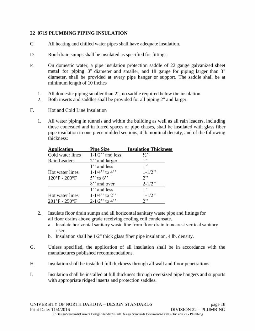
22 0719 PLUMBING PIPING INSULATION
C. All heating and chilled water pipes shall have adequate insulation.
D. Roof drain sumps shall be insulated as specified for fittings.
E. On domestic water, a pipe insulation protection saddle of 22 gauge galvanized sheet
metal for piping 3" diameter and smaller, and 18 gauge for piping larger than 3"
diameter, shall be provided at every pipe hanger or support. The saddle shall be at
minimum length of 10 inches
1. All domestic piping smaller than 2”, no saddle required below the insulation
2. Both inserts and saddles shall be provided for all piping 2" and larger.
F. Hot and Cold Line Insulation
1. All water piping in tunnels and within the building as well as all rain leaders, including
those concealed and in furred spaces or pipe chases, shall be insulated with glass fiber
pipe insulation in one piece molded sections, 4 lb. nominal density, and of the following
thickness:
Application Pipe Size Insulation Thickness
Cold water lines 1-1/2’’ and less ½’’
Rain Leaders 2’’ and larger 1’’
1’’ and less 1’’
Hot water lines 1-1/4’’ to 4’’ 1-1/2’’
120°F - 200°F 5’’ to 6’’ 2’’
8’’ and over 2-1/2’’
1’’ and less 1’’
Hot water lines 1-1/4’’ to 2’’ 1-1/2’’
201°F - 250°F 2-1/2’’ to 4’’ 2’’
2. Insulate floor drain sumps and all horizontal sanitary waste pipe and fittings for
all floor drains above grade receiving cooling coil condensate.
a. Insulate horizontal sanitary waste line from floor drain to nearest vertical sanitary
riser.
b. Insulation shall be 1/2" thick glass fiber pipe insulation, 4 lb. density.
G. Unless specified, the application of all insulation shall be in accordance with the
manufactures published recommendations.
H. Insulation shall be installed full thickness through all wall and floor penetrations.
I. Insulation shall be installed at full thickness through oversized pipe hangers and supports
with appropriate ridged inserts and protection saddles.

UNIVERSITY OF NORTH DAKOTA – DESIGN STANDARDS page 19
Print Date: 11/4/2016 DIVISION 22 – PLUMBING R:\DesignStandards\Current Design Standards\Full Design Standards Documents-Drafts\Division 22 - Plumbing
J. All insulation work under contract shall be done by skilled, competent workmen familiar
with this type of work. All insulation work shall present a neat, finished and workman
like appearance.
K. Insulation shall be applied over dry clean surfaces, butting adjoining sections firmly
together.
L. All insulation, jackets and PVC coverings shall have a flame spread rating of 25 percent
or less and a smoke developed rating of 50% or less.
M. Exterior or Exposed Piping
1. Apply metal or PVC jacket with 2" overlap at seams and joints.
a. Seal seams and joints weather tight with manufacturers recommended
sealant.
b. Apply the jacket such that the longitudinal seam is on the bottom of
pipe. 1. When using metal jacket, secure jacket with stainless steel bands every
12" at end joints.
22 1005 PLUMBING PIPING
A. Plumbing piping material shall be soldered, crimped, pressed, threaded, glued, no hub or
welded. All parts and materials must be lead free. Victaulic piping may be accepted
where it is applicable and code allows. If Victaulic piping is used the system needs to be
rated for failure temperatures, not just normal operating temperatures. The engineer of
record must provide the failure temperatures for each system and provide a 15-year
warranty from the vendor at the failure ratings.
1. Sanitary System Type: Standard cast iron pipe system or schedule 40 PVC│ABS. If
copper is used for drain lines, use only Type "L" hard copper tubing, not DWV weight
copper.
2. Cold & Hot Water System Type: Copper pipe system with all lead free components.
Plastic may be used when approved upon request.
B. Service isolation valves should be provided for plumbing systems to prevent shutting
down an entire building to work on a bathroom, drinking fountain, etc. All bathroom
groups should have isolation valves, all floors should have the ability to be isolated
independently and where capable wings of floors should have isolation valves. All
isolation valves shall be accessible in ceilings or access panels. Final valve locations are
to be clearly identified on mechanical drawings provided to Facilities Management
C. Pipes penetrating exterior walls must be installed to prevent breakage when building settles
or go through expansion and contraction due to temperature changes. Use metallic pipe
for five-foot minimum distance outside building perimeter. Prefer spools cast in walls
with hubs on either sides, or packed sleeves.

UNIVERSITY OF NORTH DAKOTA – DESIGN STANDARDS page 20
Print Date: 11/4/2016 DIVISION 22 – PLUMBING R:\DesignStandards\Current Design Standards\Full Design Standards Documents-Drafts\Division 22 - Plumbing
D. Any floor drain or sump pit and associated piping that could potentially be used to
dump hot liquids such as condensate for a temporary amount of time will be of a
metallic material as to not damage the drain, pump or piping. A minimum of 15 feet of
metal pipe is to be used. Pump must be rated for high temperature. UND Plumbing
Shop is to approve the drains; Engineer is to design.
E. At every point where piping and duct work penetrate a floor slab, except slabs on grades,
a cast -in sleeve or other curbing at least 1" high must be provided so that any leakage of
water or liquids must be at least 1” deep in order to spill through floor penetrations.
F. Sump drains shall be piped to the storm sewer, unless prior approval is given by UND
Mechanical Ops Coordinator. If piped outside, the water should not run over any existing
pedestrian walks or driveways. Provide proper slope away from the building for drainage.
G. For future use, main runs of piping shall utilize plugged tees instead of elbows. All plugs
must be anchored, secured, and leak proof but must be available for future use.
H. Valves need to be of quality design and materials to ensure they move freely and seal
tightly after sitting for more than a year and to be of adequate quality in order to maintain
that performance after 20 years. Valves should be constructed of proper materials to
prevent corrosion or rusting, especially with valves exposed to moisture or condensation.
All valve components are to be lead free. Lead free valves with packing nut are required
and a minimum rating of 300 WOG. Provide full-port ball valves at all water lines up to
3 inches in diameter whenever possible. Over 3” can be of the gate or globe style valves.
Butterfly valves will not be acceptable unless approved by UND Mechanical Operations
Coordinator beforehand.
I. Each restroom plumbing fixture supply and drain line tree shall be easily accessible
within a chase with access to the chase through a full height door. Install the chase with
a minimum width of three (3) feet.
J. All pipes should be accessible to work on by use of tunnels, chases, crawl spaces,
accessible ceilings, etc.
K. All floors susceptible to water shall drain to floor drains. Indicate the floor pitch on the
drawings.
L. All building sanitary drainage systems with fixtures below grade shall incorporate
backflow prevention strategies, e.g. backwater valves, knife gate valves or sewage
ejectors.
22 1006 PLUMBING SPECIALTIES
A. No roof drains shall be placed over joints.
B. All roof drains shall be run internally.
UNIVERSITY OF NORTH DAKOTA – DESIGN STANDARDS page 21
Print Date: 11/4/2016 DIVISION 22 – PLUMBING R:\DesignStandards\Current Design Standards\Full Design Standards Documents-Drafts\Division 22 - Plumbing
C. The base of all storm and sanitary sewer stacks shall have a clean-out. Clean-out plugs
should be set with a suitable lubricant to facilitate removal.
D. Hose bibs should be provided at 100 ft. intervals for exterior use (frost-proof type). All
bibs should be key operated with inside valve control. All cooling towers and air cooled
chillers must have a hose bib within 10 feet of its location. This must be approved by
the HVAC Systems supervisor.
E. Floor drain design shall include enough slope to provide for proper drainage. This is
especially important if ceramic floor tile is to be installed.
F. Refer to Part 1 of the Grand Forks City Code: Chapter XV Waterworks & Sewage
Systems: Article 8 Fats, Oils, and Grease (FOG) Control. Any additional changes need
to be approved by UND Facilities Management. Check for updated versions at the
Grand Forks website.
G. All food service establishments possessing cook sinks, floor troughs, floor sinks,
pulpers, extractors (excluding hand sinks), are required to install grease interceptors to
prevent the discharge of FOG to the public sewer system. Grease interceptors shall be
approved at the time of design. Grease interceptors shall be installed to receive the
drainage from plumbing fixtures and equipment with grease-laden wastewater located
in food service establishments.
H. Schier and Highland Tank are acceptable grease interceptor brands to use on campus
1. When a Highland Tank grease interceptor is used, a hot water hose faucet is
required to clean out the tank.
I. Grease interceptors are not required for residential users.
J. All food service establishments shall implement and adhere to the best management
practices that are part of the city’s FOG control program.
K. Except as provided herein, food waste disposal units shall be removed from all existing
food service establishments.
1. However, a food service establishment may continue to operate a food waste
disposal unit provided that it is operated with the use of a screen.
2. All food waste disposal units are required to have an Insinkerator Mini-Waste
Xpress System.
3. Failure to utilize a screen shall be basis for an order requiring the removal of the
food waste disposal unit at the expense of the food service establishment.
L. Food waste disposal units, including grinders, garbage grinders, or garbage disposals,
shall not be allowed in any newly constructed food service establishment.

UNIVERSITY OF NORTH DAKOTA – DESIGN STANDARDS page 22
Print Date: 11/4/2016 DIVISION 22 – PLUMBING R:\DesignStandards\Current Design Standards\Full Design Standards Documents-Drafts\Division 22 - Plumbing
M. To minimize the discharge of FOG into the sanitary sewer system, best management
practices shall be implemented by all food service establishments. This includes kitchen
practices and employee training that are essential in minimizing FOG discharges. These
best management practices are listed in the city’s FOG control program. Food service
establishments are required to maintain all grease removal devices in accordance with
the language of this article.
N. All new food service establishments shall install grease interceptors in accordance with
the Uniform Plumbing Code (UPC).
O. All food service establishments are required to submit the drainage plumbing plans to
the environmental specialist or designated representative for approval prior to
construction. Failure to submit plans or construct on accordance with approved plans is
a violation of this article.
P. New facilities are required to maintain a grease interceptor by this, or other applicable
ordinances. The new facilities shall install such a unit prior to commencement of
discharge into the sanitary sewer.
Q. If a new food service establishment has no dishwasher but has a triple compartment
sink, a mop sink, and hand sinks, the city may waive the necessity of installing an
interceptor. The city will determine whether a facility, based upon its operations and
kitchen fixtures, shall be required to install an interceptor.
R. The city may also determine whether plumbing fixtures may be connected to the
sanitary sewer line separate from the domestic sanitary sewer line. In such Instances:
1. The separate sanitary sewer line shall be equipped with a cleanout located outside
of the building to allow access for sampling.
2. The city may determine through sampling that the facility’s discharge exceeds the
city’s limit for fat’s oils, and grease, whether emulsified or not, of one hundred
(100) mg/l. In such instances:
a. The user shall be required to install an appropriately sized interceptor. The
separate sanitary sewer line is to allow easier installation of an interceptor
should one be required if there is a significant amount of oil and grease
present in the discharge.
b. This line may be combined with the domestic sanitary sewer at a point after
this cleanout.
S. Existing food service establishments not equipped with a grease interceptor shall install
an adequately sized grease interceptor when the kitchen is remodeled involving
structural renovations in their food preparation area including the sewer system or if the
discharge causes excessive grease accumulation in the sanitary sewer.

UNIVERSITY OF NORTH DAKOTA – DESIGN STANDARDS page 23
Print Date: 11/4/2016 DIVISION 22 – PLUMBING R:\DesignStandards\Current Design Standards\Full Design Standards Documents-Drafts\Division 22 - Plumbing
1. An existing food service establishment changing from one class of facility to
another shall be required to install an approved grease interceptor.
T. All grease interceptors shall be constructed in accordance with chapter 4-02 of the
Uniform Plumbing Code.
1. There shall be a minimum of one manhole per ten feet of interceptor length to
provide access for cleaning.
2. Manhole covers shall be gas-tight in construction and have a minimum opening
dimension of 24”. Concrete covers are not acceptable.
3. In areas where traffic may exist, the interceptor shall be designed for the
appropriate traffic load.
4. The access manholes shall extend at least to finished grade and be designed and
maintained to prevent surface and ground water from entering the grease
interceptor.
5. The size, type, and location of each grease interceptor shall be approved by the
environmental specialist or authorized representative before each installation
although interceptors are usually located outside the facilities.
6. The city is authorized to make determinations of grease interceptor adequacy and
need, based upon review of relevant information regarding grease interceptor
performance, maintenance, and facility site and building plan review and to
require repairs to and modification or replacement of such interceptors.
7. The minimum approved grease interceptor size is 750 gallons and the maximum
approved size is 2,000 gallons, working capacity.
U. Grease traps shall be sized according to fixture volume to allow for proper FOG
removal.
V. In the event that an outside grease interceptor is not practical in the new construction, a
grease trap(s) shall be required on waste lines leading from kitchen floor drains, mop
sinks, food preparation and washing sinks, and other fixtures or equipment where grease
may be introduced into the sewer system.
W. Food service establishments that have grease traps or that are required to install them
are subject to the requirements below:
1. The grease trap may be set on the floor or partially or fully recessed in the floor to
suit piping and structural conditions. Baffle systems and all other internal pieces
shall be removable to facilitate cleaning and replacement, but must be in place at
all other times.
2. All grease traps, flow control, air intake, and interceptors shall be installed to
manufacturer’s specifications and shall be provided with proper venting. In

UNIVERSITY OF NORTH DAKOTA – DESIGN STANDARDS page 24
Print Date: 11/4/2016 DIVISION 22 – PLUMBING R:\DesignStandards\Current Design Standards\Full Design Standards Documents-Drafts\Division 22 - Plumbing
addition, the grease traps shall be installed with sufficient clearance for the
removal of trap cover for cleaning.
22 1500 GENERAL SERVICE COMPRESSED AIR SYSTEMS
22 3000 PLUMBING EQUIPMENT
A. Domestic water heaters should be located in a heated area as close as possible to the
larger demand sources.
1. Each domestic water heater shall have a service area of 4’-0” by 4’-0” in front of
the unit clear of obstructions.
B. Steam hot water heaters shall be instantaneous. The style installed shall be one that is
easy to service, requires low maintenance and has economical parts for replacement.
Our requirement for steam water heater is Cemline. For ease of coil removal during
maintenance horizontal water heaters are to be specified unless approved by the UND
Plumbing Supervisor.
1. AO Smith or Bradford White is the requirement for gas or electric water heater brands.
22 4000 – PLUMBING FIXTURES
A. The plumbing system shall be designed to provide excellent service to the occupants
and incorporate water saving fixtures. The plumbing system shall utilize fixtures and
components that are easily replaceable, economical and that have ready local access to
replacement parts and components.
B. Fixtures
1. Floor mounted toilets (1.28 - 1.6 GPF) shall be white, elongated supplied by Kohler
with open front seats
2. Provide wall hung water closets (1.28 - 1.6 GPF) supplied by Kohler with white, elongated,
open front seats.
3. Toilet seats shall be white elongated open front with self-sustaining hinge and no cover.
4. For non-tank style water closets install automatic flush valves (1.28 - 1.6 GPF)
supplied by Sloan.
5. White Vitreous China Urinals supplied by Kohler are preferred with flush valves
(1/2 GPF) supplied by Sloan.
6. Vitreous china lavatories supplied by American Standard or Kohler. 7. Moen, Kohler, or Sloan commercial grade faucets with lever handles on all lavatories
and sinks.
b. Use water saver aerators in all sinks and wash basins.
8. Sloan hands free lavatory faucets with electric power and battery backup.
9. Moen or Symmons shower valves.
a. Water saver shower heads should be installed in all shower rooms.
10. Elkay electric water coolers constructed of stainless steel with bottle fillers.

UNIVERSITY OF NORTH DAKOTA – DESIGN STANDARDS page 25
Print Date: 11/4/2016 DIVISION 22 – PLUMBING R:\DesignStandards\Current Design Standards\Full Design Standards Documents-Drafts\Division 22 - Plumbing
11. Elkay or Dayton stainless steel kitchen and bar sinks.
C. All laboratories shall be supplied with emergency shower and eye wash stations per code.
D. For a specific list of approved fixtures, see cutsheets located at V:\UND Design
Standards\Division 22 – Plumbing\Standard PL Fixtures
22 4300 – HEALTHCARE PLUMBING FIXTURES
A. Lavatories: Typical sink installations are Kohler Greenwich K2032-0 vitreous china
white 20- ¾” x 18 ¼” (4” center) vitreous china white ADA lavatory with back-splash
and back wall mount. Preference for lavatory faucets is Kohler Triton K-7404-5A
complete lavatory faucet with ADA compliant wrist blade handles and aerator. For
sinks, we understand that, based on the application, different sinks may be desired. If
the design is different from what is listed here, Facilities Management will want to
review the recommendation prior to approving, to ensure what is selected will be easy to
clean and service.
22 6005 – MEDICAL AIR, GAS AND VACUUM SYSTEMS