divergence and flutter behavior of beck׳s type of laminated box beams
TRANSCRIPT

Author's Accepted Manuscript
Divergence and flutter behavior of Beck’s typeof laminated box beams
Nam-Il Kim, Jaehong Lee
PII: S0020-7403(14)00149-0DOI: http://dx.doi.org/10.1016/j.ijmecsci.2014.04.014Reference: MS2708
To appear in: International Journal of Mechanical Sciences
Received date: 19 June 2013Revised date: 8 March 2014Accepted date: 18 April 2014
Cite this article as: Nam-Il Kim, Jaehong Lee, Divergence and flutter behaviorof Beck’s type of laminated box beams, International Journal of MechanicalSciences, http://dx.doi.org/10.1016/j.ijmecsci.2014.04.014
This is a PDF file of an unedited manuscript that has been accepted forpublication. As a service to our customers we are providing this early version ofthe manuscript. The manuscript will undergo copyediting, typesetting, andreview of the resulting galley proof before it is published in its final citable form.Please note that during the production process errors may be discovered whichcould affect the content, and all legal disclaimers that apply to the journalpertain.
www.elsevier.com/locate/ijmecsci

Resubmitted to IJMS-D-13-00457
Divergence and flutter behavior of Beck’s type
of laminated box beams
Nam-Il Kim, Ph.D. Research Professor, Department of Architectural Engineering, Sejong University,
98 Kunja Dong, Kwangjin Ku, Seoul 143-747, S. Korea Phone) 82-10-6668-7656, E-mail) [email protected]
AND
Jaehong Lee, Ph.D. (corresponding author)
Professor, Department of Architectural Engineering, Sejong University, 98 Kunja Dong, Kwangjin Ku, Seoul 143-747, S. Korea
Phone) 82-2-3408-3287, E-mail) [email protected]
This is an original paper which has neither previously, nor simultaneously, in whole or in part, been submitted anywhere else.
No. of pages: (34) (after this page), No. of Tables: (3), No. of Figures: (11)
Keywords: Laminated box beam, Vibration, Buckling, Finite element analysis

1
ABSTRACT
The divergence and flutter behavior of Beck’s type of laminated box beams are investigated based on the finite
element model. Mechanics of laminated box beam with non-symmetric lay-up is presented based on kinematic
assumptions consistent with Vlasov beam theory. To obtain mass-, elastic stiffness-, geometric stiffness-,
damping-, and load correction matrices, the extended Hamilton’s principle is employed. Evaluation procedures
for critical values of divergence and flutter with and without damping effects are briefly introduced. Through
numerical examples, influences of fiber angle change, non-conservative parameter, external (viscous fluid) and
internal (material) damping on divergence and flutter loads of laminated box beams subjected to a subtangential
force are newly presented.
1. Introduction
In structural engineering fields, flexible structures experience conservative forces, non-conservative forces,
etc. The subtangential forces are forces whose line of action is affected by deformation of the elastic system on
which they act. Such forces are non-conservative, if the virtual work which they do cannot be represented as the
variation of a potential. Some examples of non-conservative systems are rocket-thrusted missiles, rotating fans
subjected to a pulsating torque and piping systems carrying fluid forces. Ships and submarines are also subjected
to hydrodynamic forces which are also non-conservative. A detailed discussion of this subject and a
comprehensive list of references can be found in the book by Leipholz [1].
There has been a considerable number of works in the last 50 years on non-conservative systems under
non-conservative forces losing their stability either by divergence or by flutter. It is known that if the type of
instability is divergence, critical forces of system can be determined by the static approach while for flutter
critical forces should be determined using the dynamic criterion.
One of interesting and important topics in dynamic stability problems has been the destabilizing effect of
small damping. If such a destabilization occurs, one should naturally not work without taking damping into
account, because it is only when the damping is considered that a safe design of the system under consideration
is possible. As there is no physical system in which damping is not involved in one form or another, research on
the dynamic stability of columns will be very meaningful. As shown in works of many authors [2-13], the
realistic modeling of any structure must include the damping effect. Ziegler [2] first discovered that damping

2
may have a destabilizing effect in a double pendulum subjected to a tangential follower force at free end, and
found that the flutter load is higher for zero damping than for vanishingly small internal damping. Semler et al.
[3] provided new physical insight into the destabilizing effect in the Beck’s problem and the cantilevered pipe
conveying fluid system. Their analysis and physical arguments were based on the energy balance between
energy input from the follower force and dissipation by damping, and showed that the phase angles between the
normal modes (in terms of the Jordan normal form) for the fluid-conveying pipe have an important role in the
stability characteristics, just like in the case of Ziegler’s pendulum model. The analysis of Ref. [3] was also
discussed in Païdoussis’s monograph [4]. Doaré [5] analyzed the effect of dissipation on local and global
stability of fluid-conveying pipes. It can be found that the critical velocity for instability of damped media can be
much lower than the critical velocity of undamped media. It is due to the destabilization by dissipation of
negative energy waves in a frequency range that was referred to as static in Ref. [6]. This phenomenon becomes
important at high values of mass ratio. Doaré and Michelin [7] investigated the effect of damping induced by
piezoelectric coupling from the flutter of a plate in an axial flow. They observed destabilization by dissipation
for negative energy waves propagating in the medium. Sugiyama and Langthjem [8] gave a physical explanation
of the mechanism behind the destabilizing effect of small internal damping in the dynamic stability of Beck’s
column. They considered both external (viscous fluid) and internal (material) damping and found the gradient of
the phase angle, evaluated at the free end of column to be the ‘valve’ which controls how much work the
follower force can do on the column during each period of oscillation.
It is well known that structural components made of composite materials are ideal for many structural
applications because of high strength-to-weight and stiffness-to-weight ratios, increased fatigue life, improved
damage tolerant nature, and their ability to be tailored to meet the design requirements of stiffness and strength.
For evaluation of divergence and flutter loads of these composite structures subjected to a non-conservative
force, a few researches have been made. Goyal and Kapania [14] studied the dynamic behavior of Beck’s type of
laminated composite beams subjected to a subtangential force by using a dynamic version of principle of virtual
work. They showed that the flutter load decreases as the fiber angle increases for unidirectional laminated beams,
and the value of non-conservative parameter becomes very important in design. The stability of a Beck’s type of
laminated column subjected to a tangential force was studied by Xiong and Wang [15] using an analytical model.
However, above researchers did not consider damping effect and their numerical studies were restricted to the
stability analysis of beams with rectangular cross-section. Kim [16,17] investigated the dynamic stability

3
behavior of Leipholz and Hauger types of laminated beams with open cross-sections and symmetric lay-ups with
respect to middle plane of each plate. However, there are two main drawbacks to utilize laminated beams with
open-sections and symmetric lay-ups. One is prone to torsional/lateral-torsional buckling due to lack of the
torsional stiffness and the other is application restriction on the use of symmetric lay-up which does not consider
the coupling effect of extension-bending.
On the other hand, thin-walled box-beams made of advanced composites become emerged as primary load
bearing structures in the construction of helicopter rotor blades, wind turbine blades, and tilt rotor blades due to
their specific stiffness in bending and torsion. Therefore, a lot of research effort [18-23] has been devoted to
model and analyze thin-walled laminated beams especially with box sections, but most of them are confined to
beams subjected to a conservative force.
The objective of the present work is to study divergence and flutter instability behavior of Beck’s type of
damped laminated box beams with symmetric and non-symmetric lay-ups subjected to a subtangential force.
The axial and flexural laminate stiffnesses with non-symmetric lay-up with respect to middle plane of a plate
which consider the coupling effect between extension and bending are derived. The finite element model by
using the extended Hamilton’s principle is applied to the present beam model based on the Hermite cubic
interpolation functions. Through numerical examples, obtained results are compared with those published results
to validate the present approach. Influences of various important structural parameters such as fiber angle
change, non-conservative parameter, external (viscous fluid) and internal (material) damping on the divergence
and flutter behavior of laminated box beams with symmetric and non-symmetric lay-ups subjected to a
subtangential force are fully discussed. The important points presented may be summarized as follows:
1. Based on the finite laminated box beam model, variation of the first and second flutter loads due to a
subtangential force is investigated and the corresponding stability diagram is presented by analyzing
eigenfrequency curves.
2. Effects of fiber angle change and non-conservative parameter on critical values of divergence and flutter
are studied.
3. Influence of external and internal damping on the instability region of the divergence-flutter system is
investigated.

4
2. Structural model of laminated box beam
2.1 Kinematics
To derive the equation of motion for a laminated box beam subjected to a subtangential force, following
assumptions are adopted.
1. Laminated beam is slender and prismatic.
2. Kirchhoff-Love assumption in a classical theory is valid for a laminated beam.
3. Cross-section is assumed to maintain its shape during deformation, so that there is no distortion.
4. Each laminate is thin and perfectly bonded.
5. Normal stress sσ in the contour direction s is small compared to an axial stress xσ .
Fig. 1 shows geometry and material and structural coordinate systems of a laminated box beam and two
sets of coordinate systems. The first coordinate system is the orthogonal Cartesian coordinate system ( ), ,x y z
and the second coordinate system is the local plate coordinate system ( ), ,n s x , wherein n axis is normal to
the middle surface of a plate element, s axis is tangent to the middle surface and is directed along the contour
line of cross-section. ‘1’ and ‘2’ correspond to directions parallel and perpendicular to fibers, respectively.
Transformation equations for expressing stresses in a structural coordinate system in terms of stresses in a
material coordinate one is presented in Ref. [24]. Displacement components u , v , and w of an arbitrary
point in a contour coordinate system are expressed in Ref. [25].
2.2 Evaluation of strain energy
In this study, the membrane shear strain and the twisting of cross-section are neglected. Therefore,
resultant constitutive relations between membrane forces, bending moment, and their corresponding strains and
curvatures for a middle plane non-symmetric laminate can be deduced from Ref. [24] as follows:
11 12 11 12
12 22 12 22
11 12 11 12
12 22 12 22
x x
s s
x x
s s
N A A B BN A A B BM B B D DM B B D D
εεκκ
⎧ ⎫ ⎧ ⎫⎡ ⎤⎪ ⎪ ⎪ ⎪⎢ ⎥⎪ ⎪ ⎪ ⎪⎢ ⎥=⎨ ⎬ ⎨ ⎬⎢ ⎥⎪ ⎪ ⎪ ⎪⎢ ⎥⎪ ⎪ ⎪ ⎪⎣ ⎦⎩ ⎭ ⎩ ⎭
(1)

5
where ijA , ijB , and ijD are extensional, extension-bending coupling, and bending stiffnesses, respectively.
Appropriate assumptions for constitutive relations are essential for a refined laminated beam theory since the
pile in laminated composites behave in a highly two-dimensional manner due to the Poisson’s effect (Smith and
Chopra [26]). In this regard, the zero hoop stress assumption ( 0)sσ = is employed in this study. Assuming
zero hoop stress leads to 0s sN M= = , then the hoop strain sε and the tangential curvature sκ of middle
surface can be expressed from Eq. (1) as follows:
( ) ( ){ }12 22 12 22 12 22 22 12222 22 22
1s x xA D B B B D B D
A D Bε ε κ= − − + −
− (2a)
( ) ( ){ }12 22 22 12 12 22 22 12222 22 22
1s x xA B A B B B A D
A D Bκ ε κ= − + −
− (2b)
where xε and xκ are the axial strain and the biaxial curvature, respectively, in the middle surface of wall.
Substituting Eq. (2) into Eq. (1) gives reduced constitutive relations as follows:
2 2
* *11 112 2 cosx
w v vN A z Bx x x
ψ⎛ ⎞∂ ∂ ∂
= − −⎜ ⎟∂ ∂ ∂⎝ ⎠ (3a)
2 2* *11 112 2 cosx
w v vM B z Dx x x
ψ⎛ ⎞∂ ∂ ∂
= − −⎜ ⎟∂ ∂ ∂⎝ ⎠ (3b)
where
2 2* 12 22 12 12 22 22 1211 11 2
22 22 22
2A D A B B A BA AA D B
− += −
− (4a)
2* 12 12 22 12 22 12 12 22 22 12 1211 11 2
22 22 22
A B D A B D B B A B DB BA D B
− − += −
−
(4b)
2 2* 12 22 12 22 12 22 1211 11 2
22 22 22
2B D B B D A DD DA D B
− += −
− (4c)

6
From the principle of virtual work by Gjelsvik [27], stress resultants of the laminated beam that are
equivalent to distributions of plate stress resultants acting on the cross-section of beam are expressed as follows:
2
11 12 2
w vF E Ex x
∂ ∂= −
∂ ∂ (5a)
2
12 22 2
w vM E Ex x
∂ ∂= −
∂ ∂ (5b)
where F and M are the axial force and the bending moment, respectively, and ijE are laminate
stiffnesses given by
*
11 11sE A ds= ∫ (6a)
( )* *12 11 11 cos
sE A z B dsψ= +∫ (6b)
( )* 2 * * 222 11 11 112 cos cos
sE A z B z D dsψ ψ= + +∫ (6c)
When origin of the contour coordinate system coincides with the principal origin, stiffness 12E in Eq. (6b) is
zero. The explicit expressions for 11E and 22E of the closed cross-section as shown in Fig. 1 are given as
follows:
( ) ( )* * * *11 11 11 11 112 2tf bf lw rwE b A A h A A= + + + (7a)
( ) ( ) ( ) ( )2 * * 3 * * * * * *22 11 11 11 11 11 11 11 11
22 4 23
tf bf lw rw tf bf tf bfE bh A A h A A bh B B b D D= + + + − + + + (7b)
where b and h are half width of flange and half height of web, respectively; superscript tf and bf
denote top and bottom flanges, respectively; lw and rw denote left and right webs, respectively. In the
linear regime, the elastic strain energy expression for the laminated box beam undergoing extension and bending
deformations is given by

7
22 2
11 22 2
12
l
E o
w vE E dxx x
⎧ ⎫⎛ ⎞∂ ∂⎪ ⎪⎛ ⎞∏ = +⎨ ⎬⎜ ⎟⎜ ⎟∂ ∂⎝ ⎠ ⎝ ⎠⎪ ⎪⎩ ⎭∫ (8)
where l denotes the length of beam.
3. Finite element formulation
The laminated box beam subjected to a combined conservative force cF and tangential follower force
tF at the tip as shown in Fig. 2 is considered. The former may be thought of as a dead load, while the latter can
be considered as a typical follower force. Note that the force is conservative for the non-conservative parameter
0α = , while it is non-conservative for 0α ≠ and is a purely tangential follower force for 1α = .
In this study, the kinetic energy M∏ , the potential energy G∏ including the work done by the
conservative component of subtangential force and the virtual work NCδ ∏ by the non-conservative
component of acting force and by damping are considered. These terms are expressed as follows:
2 2 21
2l
M o
w v vA I dxt t x
ρ ρ⎡ ⎤⎧ ⎫∂ ∂ ∂⎪ ⎪⎛ ⎞ ⎛ ⎞ ⎛ ⎞∏ = + +⎢ ⎥⎨ ⎬⎜ ⎟ ⎜ ⎟ ⎜ ⎟∂ ∂ ∂⎝ ⎠ ⎝ ⎠ ⎝ ⎠⎢ ⎥⎪ ⎪⎩ ⎭⎣ ⎦
∫ (9a)
212
l
G o
vF dxx
∂⎛ ⎞∏ = − ⎜ ⎟∂⎝ ⎠∫ (9b)
3 2
1 2 2 2
( ) ( )l
NC o
v v v v lv dx F v lt t x x x
δ γ δ γ δ α δ⎧ ⎫⎛ ⎞∂ ∂ ∂ ∂⎪ ⎪∏ = − + −⎨ ⎬⎜ ⎟∂ ∂ ∂ ∂ ∂⎪ ⎪⎝ ⎠⎩ ⎭
∫ (9c)
where ρ is the mass density; 1γ and 2γ are external and internal damping coefficients, respectively; t
and δ are time and variation, respectively.
To construct the finite element formulation, we consider the beam element which has length el with
element nodal displacements ( , , ,p p pw v ϕ , ,q q qw v ϕ ) at two ends of p and q as shown in Fig. 2.
Introducing for convenience the following local and dimensionless coordinates:

8
( 1) ex x i l= − − , e
xl
ξ = (10)
where i represents the i -th element. The displacement field can be approximated by means of the following
relation:
1 2( , ) p qw x t N w N w= + (11)
3 4 5 6( , ) p p q qv x t N v N N v Nϕ ϕ= + + + (12)
where
1 1N ξ= − , 2N ξ= , 2 33 1 3 2N ξ ξ= − + ,
( )2 34 2eN l ξ ξ ξ= − + − , 2 3
5 3 2N ξ ξ= − , ( )2 36 eN l ξ ξ= −
(13)
Applying the extended Hamilton’s principle with the aid of Eqs. (11) and (12), the discrete equation of motion
can be written in terms of nodal displacements in the following form:
( ){ }2
1
0t T T T T
e g nctdtδ δ δ δ− − + − − =∫ u mu u cu u k k k u u f (14)
where u and f are nodal displacement and force vectors, respectively; m is the mass matrix; ek and
gk are the elastic stiffness matrix and the geometric stiffness matrix due to an axial force, respectively; nck
is the load correction matrix due to directional change of non-conservative force; c is damping matrix due to
the external and internal damping represented by linear combination of mass matrix and elastic stiffness matrix.
Finally, by applying the standard finite element method, the differential equation of motion governing the entire
structure can be derived.
( )e g nc+ + + − =MU CU K K K U F (15)

9
where M , C , and eK are the mass-, damping-, and elastic stiffness matrices, respectively, of total system;
gK and ncK are the geometric stiffness matrix and the load correction matrix due to a non-conservative
force, respectively, of total system.
4. Dynamic stability analysis
Evaluation procedures to determine divergence and flutter loads of a non-conservative system are shortly
described. Here, the global stiffness matrix of system is asymmetric due to the effect of a non-conservative force
so that IMSL [28] subroutine which can provide the complex eigenvalue of asymmetric matrix equation is used
in the present study.
4.1 Free vibration analysis
For free vibration analysis of laminated box beam, the equation of motion results in an eigenvalue
problem by letting U be i te ω H as follows:
2 0e ω⎡ ⎤− =⎣ ⎦K M H (16)
where i 1= − ; ω and H are the circular frequency and the corresponding right eigenvector, respectively.
4.2 Critical forces for divergence and flutter without damping
In case of the static equilibrium state for a non-conservative system without damping effects, the mass
matrix M , the damping matrix C , and the force vector F in Eq. (15) are neglected. Resultantly, the
eigenvalue problem is expressed as follows:
( ) 0e g ncλ⎡ ⎤− − =⎣ ⎦K K K U (17)
where λ is the proportionality parameter and by calculating λ in Eq. (17), the critical divergence load dF
of system is determined. For the case of conservative force, the force potential function usually exits and ncK
is zero. The dynamic criterion considers small oscillations about the equilibrium position, and reduces to the
10
following equation.
( ) 0e g ncλ⎡ ⎤+ − − =⎣ ⎦MU K K K U (18)
Eq. (18) can be expressed as a double eigenvalue problem by letting U be i te ω H as follows:
( ) 2 0e g ncλ ω⎡ ⎤− − − =⎣ ⎦K K K M H (19)
From Eq. (19), by constructing eigenfrequency curve which shows variation of frequencies 2ω with increase
of the proportional parameter λ , dynamic stability behavior of an undamped non-conservative system may be
traced. That is to say, all 2ω are real and positive numbers in case that λ is small. But as λ increases
gradually, the first and the second frequencies of 2ω approach each other and the stability is lost when two
consecutive eigenvalues of 2ω become equal at a finite critical value of λ . At this point, the critical flutter
load fF occurs.
4.3 Critical force for flutter with damping
The unstable dynamic equilibrium state of the non-conservative system with damping effects is considered.
In this case, the equation of motion in Eq. (15) can be written as follows:
( ) 0e g ncλ⎡ ⎤+ + − − =⎣ ⎦MU CU K K K U (20)
By putting the nodal velocity vector U as an independent variable V , Eq. (20) is transformed into
following two simultaneous differential equations of the first order.
=MU MV (21a)
( ) 0e g ncλ⎡ ⎤+ + − − =⎣ ⎦MV CV K K K U (21b)
Next by putting i te ω=U Q and i te ω=V S , Eq. (21) can be expressed as the following eigenvalue

11
problem.
iω =AD BD (22)
where
00
⎡ ⎤= ⎢ ⎥
⎣ ⎦
MA
M, ( )
0
e g ncλ
⎡ ⎤= ⎢ ⎥
− + − −⎢ ⎥⎣ ⎦
MB
K K K C, { }, T=D Q S (23)
In case of a damped non-conservative system with small value of λ , the frequency ω ( i)μ η= ±
become complex conjugate. Application of Lyapunov’s stability definition [29] which is the most used gives that
vibrations are stable if all real values μ < 0 and unstable if at least one μ > 0. If 0μ = , it has the critical
flutter load fF of the damped system.
5. Numerical examples
The dynamic stability analysis of isotropic and laminated beams is performed based on the present finite
element method. Through numerical examples, effects of various important parameters (e.g. fiber angle change,
non-conservative parameter, external and internal damping) on the divergence and flutter behavior of laminated
box beams are parametrically studied. Here the fiber angle and the beam’s mechanical and geometrical
properties are assumed to be uniform throughout beam.
5.1 Flutter load for an isotropic beam
In order to validate the present numerical method considering the damping effect, the laminated beam is
treated as an isotropic material with following mechanical properties: A = 2×10⁻³ m2, I = 1.66666×10⁻⁸ m4,
l = 1 m, E = 2.1×10⁸ kN/m2, ρ = 15700 kg/m3. For a cantilevered beam subjected to a tangential force (α =
1) acting at the tip of beam, fundamental flutter loads *fF are presented in Table 1 with respect to various
internal damping parameters. For comparison, results by Rao and Rao [30] who obtained solutions from the
finite difference method are presented. In Table 1, the dimensionless force parameter is defined as *F =

12
2Fl EI . It can be found from Table 1 that present results are found to be in excellent agreement with those by
Rao and Rao [30]. It can also be found that the present model using 4 finite beam elements shows excellent
convergence. Based on the convergence test, entire length of beams is modeled using 8 elements in subsequent
examples.
5.2 Laminated beam with symmetric lay-ups
A laminated box beam as shown in Fig. 1 with symmetric lay-ups is considered. It is assumed that width
2b and height 2h are 0.3 m and 0.6 m, respectively, length l is 12 m and total thicknesses of flanges and
webs are 0.03 m. The graphite-epoxy (AS4/3501) is used with its material properties: 1E = 144 GPa, 2E = 3E =
9.65 GPa, 12G = 13G = 4.14 GPa, 23G = 3.45 GPa, 12ν = 13ν = 0.3, 23ν = 0.5, ρ = 1389 kg/m3. All constituent
flanges and webs are assumed to be symmetrically laminated with respect to its middle plane and 4 layers with
equal thickness are considered in flanges and webs. Considered laminate schemes are: [0]4, [0/90]S, and
[45/-45]S.
To show accuracy of the elastic stiffness matrix and the mass matrix developed by this study, the lowest
three natural frequencies for the simply supported laminated beam are presented and compared with analytical
solutions by Cortínez and Piovan [20] in Table 2. From Table 2, it can be found that results from this study are
in good agreement with solutions from Cortínez and Piovan [20] for fiber angles under consideration.
Next, for a cantilevered beam with [15/-15]S lay-up subjected to a subtangential force acting at the free
end, eigenfrequency curves are plotted in Fig. 3 with respect to various values of α . Here the applied force
becomes non-conservative as α takes value other than zero. In this example, the dimensionless force
parameter * 2 22( )F F l E Ah= and the dimensionless frequency parameter 4 2 1 2
2( )l E hω ρΩ = are
used. It can be found from Fig. 3 that divergence occurs at Ω = 0 and the first divergence load increases as α
increases, whereas the second one decreases with decrease of α . Flutter occurs via coalescence of the first and
second eigensolutions. For this reason, the first flutter mode is principally a linear combination of the first and
second eigenmodes. In Fig. 4, variation of the real and imaginary values of Ω versus a subtangential force for
various α is presented. It is seen in Fig. 4(a) that when α = 0.5, as a subtangential force increases, *μ
decreases to zero, at which divergence takes place and increases up to occurrence of the first flutter load. The

13
imaginary value is zero before occurrence of the flutter load and increases suddenly after that as shown in Fig.
4(b). It is known from the study by Sugiyama and Langthjem [8] that as there is no energy dissipation, the
subtangential force cannot produce any energy either. Accordingly, the phase angle gradient at the free end is
zero. That is, the subtangential force of Beck’s type of beam without damping is conservative in the sense that
there is no energy input from it as long as it is subcritical. It is non-conservative only when the force parameter
*F exceeds the critical value *crF .
To study influence of fiber angle change on the instability behavior, eigenfrequency curves for a
cantilevered beam with [ /ψ ψ− ]S lay-ups are depicted in Fig. 5 with respect to various α . As can be seen in
Fig. 5, for α = 0.33, the first and second frequencies approach each other as *F increases gradually and
stability is lost when two consecutive eigenvalues of 2Ω become equal at the finite critical value of *1fF .
After that, the second flutter *2fF happens at load level, in which the first and second frequencies coincide as
*F increases. For all lay-ups, divergence occurs when α ≤ 0.5 and pure flutter occurs for α > 0.5.
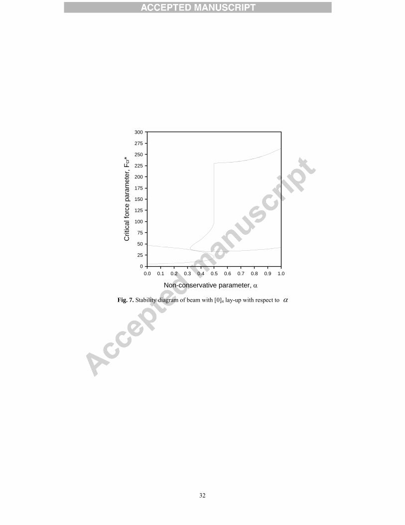
Fig. 6 shows variation of the lowest two divergence and flutter loads under conservative (α = 0) and
tangential (α = 1.0) forces with respect to the fiber angle change. It is seen that as fiber angle increases, values
of divergence and flutter loads sharply decrease down to the fiber angle ψ = 50° and have minimum values
around ψ = 75°. This is due to the fact that bending stiffness 11D of box beam has the smallest one around
ψ = 75°. In case of the first divergence load with α = 0 as shown in Fig. 6(a), it increases as α increases
regardless of fiber angle change and significantly increases around α = 0.5 since the gradient of the first
divergence load is the highest at α = 0.5 as shown in Fig. 7. On the other hand, the second divergence load
drops significantly around α = 0.5 which is contrary to the first divergence behavior. It is interesting to find
that the first flutter load with α = 0.4 is larger than that with α = 0.5 or 0.6 as shown in Fig. 6(c) and the
second flutter load increases with increase of α unlike the second divergence behavior, and it suddenly jumps
at α = 0.5 as shown in Fig. 6(d), at which the third and fourth frequencies coalesce.
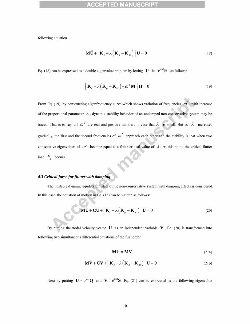
To further investigate the divergence and flutter behavior of laminated box beam, stability diagram of
beam with [0]4 lay-up is depicted in Fig. 7. As seen in Fig. 7, the instability mechanism of system is the
divergence system (DS) for values of 0.0 ≤α < 0.32 and the first and second flutter occur together with

14
divergence at 0.32 ≤α ≤ 0.5, which corresponds to the divergence-flutter system (DFS). Pure flutter without
divergence which means the flutter system (FS) occurs at α > 0.5. It can also be observed that the second
flutter load jumps at α =0.5, which corresponds to the transition point from DFS to FS, and it increases with
increase of α in FS. This jumping phenomenon is due to the reason that not only the first flutter but also the
second flutter occurs at the load level in which the first and the second frequencies coincide in DFS, whereas the
second flutter occurs when the third and fourth frequencies become equal in FS. For other lay-ups, the same
phenomenon can be observed.
We consider cantilevered beams with three cases of lay-ups subjected to a conservative force and a
tangential force. Lay-ups are given by: Case 1: [ /ψ ψ− ]S lay-up for both flanges and webs, Case 2:
[ /ψ ψ− ]S lay-up for flanges and [0]4 lay-up for webs, Case 3: [0]4 and [ /ψ ψ− ]S lay-ups for flanges and
webs, respectively. Fig. 8 shows the relative rate of increase for divergence and flutter with Cases 2 and 3 with
respect to that of beam with Case 1. It reveals that critical forces of divergence and flutter for Case 3 is the
highest and followed by Case 2 and Case 1. The rate of increase sharply grows at 20º ≤ψ ≤ 60º and has the
maximum value around ψ = 70° since the bending stiffness 11D decreases significantly at above range of
fiber angle. Thus, the unidirectional [0]4 lay-up in flanges or webs leads to the higher divergence and flutter
loads, and its effect in flanges is larger than that in webs.
We also proceed to study an influence of external and internal damping on flutter behavior of laminated
box beam. The cantilevered beam with Case 1 lay-up is subjected to a subtangential force. From relation
between the damping coefficient and the proportional damping parameter, the external damping *1γ and the
internal one *2γ can be given as follows:
( ){ }1 2 1 2 2 1*1 2 2
1 2
2 iξ ξγ
Ω Ω Ω − Ω=
Ω − Ω,
( )2 2 1 1*2 2 2
1 2
2 iξ ξγ
Ω − Ω=
Ω − Ω (24)
where 1Ω and 2Ω are the first and second dimensionless frequencies, respectively, and jξ ( j = mode
number) is the proportional damping parameter.
For a cantilevered beam with [45/-45]S lay-up, fluctuation of the real value *μ of frequency is plotted in

15
Fig. 9 with respect to a tangential force *F . It is noted that vibration is stable if all *μ < 0, and unstable if at
least one *μ > 0. The stability is termed divergence if *η = 0 for the unstable eigenvalue, and flutter if *η ≠ 0
and the imaginary part *η corresponding to *μ = 0 is termed the flutter frequency. The real part *μ of the
complex eigenvalue Ω for a specific value of *F can be referred to as the amplitude growth factor of the
flutter motion [31]. It is seen in Fig. 9(a), the flutter load increases with increase of internal damping *2γ . That
is, increasing the amount of internal damping has a stabilizing effect for larger values. On the other hand, the
dependence of the flutter load on the internal damping *2γ becomes more complicated when external damping
*1γ is included. It is the mutual balance between *
1γ and *2γ which governs the magnitude of the flutter
load. This is understandable in the energy aspect in that introduction and increase of internal damping imply
naturally an increasing value of its work. However, increase of *2γ implies that the work done by external
damping decreases, and this decrease of work leads to the reduction of frequency as shown in Fig. 9(b). For
other lay-ups, results show similar behavior.
Fig. 10(a) shows the stability diagram with [45/-45]S lay-up considering only internal damping *2γ for
the first flutter load. It is seen that the critical flutter load with small internal damping reduces to roughly half of
value of the undamped flutter load. The jump in flutter loads from 4.318 to 2.360 for α = 1.0 when vanishingly
small internal damping is introduced is known as the ‘destabilization paradox of small internal damping’. This
can be expressed in the light of the energy balance concept between energy input from the non-conservative
force and dissipation by internal damping. The destabilizing effect of small internal damping may be caused by
the rapid decrease of the phase angle gradient at the free end. This implies that the critical flutter load *fF must
decrease in order to maintain the energy balance with damping forces, as the dissipation only increases
moderately with the internal damping *2γ [8]. After that, the flutter load increases with increase of *
2γ which
means the stabilizing effect for large values of *2γ . It is interesting to find that as *
2γ increases, value of
flutter load decreases in the region of DFS (α < 0.5) and flutter loads have the same values at α = 0.5 even the
value of *2γ is different. It can also be observed that in case of *
2γ = 0, DFS occurs at 0.32 ≤α ≤ 0.5, while

16
*2γ = 0.0001 extends the range of instability region for DFS to 0.34 ≤α ≤ 0.5. As *
2γ increases, it extends the
DFS region to 0.30 ≤α ≤ 0.5 for *2γ = 0.01 and 0.24 ≤α ≤ 0.5 for *
2γ = 0.02. Finally, the stability diagram with
various *1γ when *
2γ = 0.0001 is depicted in Fig. 10(b). It is seen that under the condition of small *2γ , the
range of instability region of DFS is unchanged regardless of *1γ . As *
1γ increases, the flutter load curve shifts
up. This implies that an increase in external damping *1γ may lower the total energy dissipation. Thus, the
external damping has a stabilizing effect which can also be proved mathematically [32].
5.3 Laminated beam with non-symmetric lay-ups
A non-symmetrically laminated box beam which has width 2b = 23.438×10⁻³ m, height 2h =
12.838×10⁻³ m, length l = 0.8445 m, and thickness τ = 0.762×10⁻³ m is considered. The material of beam is
graphite-epoxy and its properties are as follows: 1E = 142 GPa, 2E = 3E = 9.8 GPa, 12G = 13G = 6.0 GPa,
23G = 4.83 GPa, 12ν = 13ν = 0.42, 23ν = 0.5, ρ = 1445 kg/m3. The specific choice of lay-up, designated
circumferentially uniform stiffness, that produces the same membrane stiffness coefficient with respect to the
local coordinate system has been adopted. This can be described in the local coordinate system as [0 ]nψ
along the entire circumference of cross-section. Accordingly, two flexural vibration modes are uncoupled.
In Table 3, for a cantilevered beam with [0/30]3 and [0/45]3 lay-ups in two flanges and webs, natural
frequencies by this study are presented and compared with those by Vo and Lee [21] using the displacement
based finite beam elements and by Qin an Librescu [22] using the extended Galerkin’s method. It can be found
from Table 3 that a good agreement between results by this study and other available methods is evident.
We also study the divergence and flutter instability for several cases of non-symmetrically laminated box
beams. Cases studied have a ply stacking sequence of 3[0 ]ψ . Results show similar behavior when compared
to those of symmetrically laminated cases. But there is a bit difference between symmetrically laminated cases
and non-symmetrically laminated ones for variation of divergence and flutter loads with respect to fiber angle
change. Fig. 11 shows variation of the first and second divergence and flutter loads. It can be observed from Fig.
11 that influence of the fiber angle change on divergence and flutter loads for non-symmetrically laminated

17
cases is smaller than that for symmetrically laminated ones, as shown in Fig. 6.
6. Conclusions
Based on the finite element model using the extended Hamilton’s principle, the stability behavior of
laminated box beams with symmetric and non-symmetric lay-ups subjected to a subtangential force was studied.
Influences of fiber angle change, non-conservative parameter, external and internal damping on the divergence
and flutter behavior are intensively investigated. Distinctions drawn from numerical examples are summarized
as follows:
1. The fundamental instability occurs by divergence at α ≤ 0.5 and the pure flutter occurs at α > 0.5 for
any directional laminated box beam.
2. The stability diagram shows that the second flutter load is discontinuous at transition point (α = 0.5).
And the first flutter load decreases slightly as α increases in the region of the divergence-flutter
system (DFS) and it again increases with increase of α in the region of flutter system (FS). While the
second flutter load increases with increase of α in both DFS and FS. The instability region remains
unchanged as one varies the fiber angle.
3. The small internal damping has a destabilizing effect. As the internal damping increases, the flutter load
decreases for α < 0.5 and it increases for α > 0.5 and flutter loads have the same value for α = 0.5
even the value of internal damping is different. The internal damping leads to increase of the range of
instability region for DFS.
4. The external damping increases, the flutter load curve shift up since the increase in external damping is
lower the total energy dissipation.
5. Influence of fiber angle on the divergence and flutter behavior of laminated box beams with
non-symmetric lay-ups is smaller than that of beams with symmetric ones.
Acknowledgements
The support of the research reported here by Basic Science Research Program through the National Research
Foundation of Korea (NRF) funded by the Ministry of Education, Science and Technology (2010-0019373 &
2012R1A2A1A01007405) is gratefully acknowledged.

18

19
References
[1] Leipholz H. Stability of elastic systems. Sijthoff and Noordhoff International Publishers BV, Alphen aan
den Rijn, the Netherlands, 1980.
[2] Ziegler H. Die stabilitätskriterien der Elastomechanik. Ingenieur Archiv 1952;20:49-56.
[3] Semler C, Alighanbari H, Païdoussis MP. A physical explanation of the destabilizing effect of damping. J
Appl Mech 1998;65:642-648.
[4] Païdoussis MP. Fluid-structure interactions: Slender structures and axial flow, vol. I, Academic Press, San
Diego, 1998.
[5] Doaré O. Dissipation effect on local and global stability of fluid-conveying pipes. J Sound Vib
2010;329:72-83.
[6] Doaré O, de Langre E. Local and global instability of fluid-conveying pipes on elastic foundation. J Fluid
Struct 2002;16:1-14.
[7] Doaré O, Michelin S. Piezoelectric coupling in energy-harvesting fluttering flexible plates: liner stability
analysis and conversion efficiency. J Fluid Struct 2011;27:1357-1375.
[8] Sugiyama Y, Langthjem MA. Physical mechanism of the destabilizing effect of damping in continuous
non-conservative dissipative system. Int J Nonlin Mech 2007;42:132-145.
[9] Kounadis AN, Simitses GJ. Local(classical) and global bifurcations in non-linear, non-gradient
autonomous dissipative structural systems. J Sound Vib 1993;160:417-432.
[10] Thomsen JJ. Chaotic dynamics of the partially follower-loaded elastic double-pendulum. Report No. 455,
Technical University of Denmark, 1993.
[11] Krätzig WB, Li LY, Nawrotzki P. Stability conditions for non-conservative dynamical systems. Comput
Mech 1991;8:141-151.
[12] El Naschie MS. Stress, stability and chaos in structural engineering. An energy approach. MaGraw-Hill,
New York, 1990.
[13] Bolotin VV, Zhinzher NI. Effects of damping on stability of elastic system subjected to non-conservative
forces. Int J Solids Struct 1969;5:965-989.
[14] Goyal VK, Kapania RK. Dynamic stability of laminated beams subjected to nonconservative loading.
Thin-Walled Struct 2008;46:1359-1369.

20
[15] Xiong Y, Wang TK. Stability of a beck-type laminated column. Proceedings of the sixth international
conference on composite materials (ICCM VI), Vol. 5, Elsevier Applied Sciences, New York, 1987.
[16] Kim NI. Dynamic stability behavior of damped laminated beam subjected to uniformly distributed
subtangential forces. Compos Struct 2010;92:2768-2780.
[17] Kim NI. Divergence and flutter instability of damped laminated beams subjected to a triangular
distribution of nonconservative forces. Adv Struct Eng 2011;14:1075-1091.
[18] Amoushahi H, Azhrai M. Buckling of composite FRP structural plates using the complex finite strip
method. Comp Struct 2009;90:92-99.
[19] Roy S, Yu W. An asymptotically correct model for initially curved and twisted thin-walled composite
beams. Int J Solids Struct 2007;44:4039-4052.
[20] Cortínez VH, Piovan MT. Vibration and buckling of composite thin-walled beams with shear deformability.
J Sound Vib 2002;258:701-723.
[21] Vo TP, Lee J. Free vibration of thin-walled composite box beams. Compos Struct 2008;84:11-20.
[22] Qin Z, Librescu L. On a shear-deformable theory of anisotropic thin-walled beams: further contribution
and validations. Compos Struct 2002;56:345-358.
[23] Song O, Librescu L. Structural modeling and free vibration analysis of rotating composite thin-walled
beams. J Am Helicopter Soc 1997;42(4):358–69.
[24] Jones RM. Mechanics of composite material, 2nd Ed. Taylor & Francis, New York, 1999.
[25] Bauld NR, Tzeng L. A Vlasov theory for fiber-reinforced beams with thin-walled open cross sections. Int
J Solids Struct 1984;20:277-297.
[26] Smith EC, Chopra I. Formulation and evaluation of an analytical model for composite box-beams. J Am
Helicopter Soc 1991;36:23-35.
[27] Gjelsvik A. The theory of thin-walled bars. Wiley, New York, 1981.
[28] IMSL. Microsoft IMSL Library. Microsoft Corporation, 1995.
[29] Bolotin VV. Non-conservative problems of the theory of elastic stability. Oxford, Pergamon Press, 1963.
[30] Rao BN, Rao GV. Stability of tapered cantilever columns subjected to a tip-concentrated follower force
with or without damping. Comput Struct 1990;37:333-342.
[31] Ryu SU, Sugiyama Y. Computational dynamic approach to the effect of damping on stability of a
cantilevered column subjected to a follower force. Comput Struct 2003;81:265-271.

21
[32] Pedersen P. Sensitivity analysis for non-selfadjoint systems, in: V. Komkov (Ed.). Proceedings of
American Mathematical Society New York Meeting, May 1983:119-130.

22
Table 1 Fundamental flutter loads of a cantilevered isotropic beam subjected to a tangential follower force
with various internal damping (α = 1.0)
Methods Internal damping ( *
2γ )
0 0.0001 0.001 0.01 0.1
No. of element
2 - - - - -
3 20.05 10.93 10.93 10.96 13.91
4 20.05 10.94 10.94 10.97 13.94
5 20.05 10.94 10.94 10.97 13.94
6 20.05 10.94 10.94 10.97 13.94
7 20.05 10.94 10.94 10.97 13.95
20 20.05 10.94 10.94 10.97 13.95
Rao and Rao [30] 20.05 10.94 10.94 10.97 13.64

23
Table 2 Natural frequencies (Hz) of simply supported laminated beams with symmetric lay-ups
Stacking sequence Methods
Mode
1 2 3
[0]4 This study
Cortínez and Piovan [20] 24.80 24.84
98.70 99.34
220.32 223.52
[0/90]S This study Cortínez and Piovan [20]
18.16 18.14
72.27 72.55
161.33 163.24
[45/-45]S This study Cortínez and Piovan [20]
8.01 8.02
31.87 32.08
71.13 72.17

24
Table 3 Fundamental natural frequencies (Hz) of cantilevered laminated beams
with non-symmetric lay-ups
Stacking sequence Vo and Lee [21] Qin and Librescu [22] This study
[0/30]3 35.53 34.58 36.71
[0/45]3 32.52 32.64 33.36

25
Fig. 1. Geometry and material and structural coordinate systems of a laminated box beam

26
Fig. 2. Laminated beam subjected to a subtangential force and discretization of system into n finite elements

27
0 10 20 305 15 25 35
Force parameter, F*
0
200
400
600
800
-100
100
300
500
700
900Fr
eque
ncy,
Ω2
α00.30.51.0
Fig. 3. Eigenfrequncy curves for [15/-15]S beams subjected to a subtangential force

28
0 10 20 305 15 25 35
Force parameter, F*
0
4
8
12
16
2
6
10
14
Rea
l val
ue, μ
∗
α0.50.60.70.80.91.0
Divergence occurs
Flutter occurs
(a) Real value *μ
0 10 20 305 15 25 35
Force parameter, F*
0
2
4
6
8
10
-1
1
3
5
7
9
Imag
inar
y va
lue,
η∗
α0.50.60.70.80.91.0
Flutter occurs
(b) Imaginary value *η
Fig. 4. Variation of real and imaginary values for [15/-15]S beams with various α

29

30
0.0 1.0 2.0 3.0 4.0 5.00.5 1.5 2.5 3.5 4.5 5.5
Force parameter, F*
0
4
8
12
16
20
24
28
2
6
10
14
18
22
26Fr
eque
ncy,
Ω2
ψ0°15°45°90°
0 2 4 61 3 5 7
Force parameter, F*
-20
0
20
40
60
80
100
120
-10
10
30
50
70
90
110
Freq
uenc
y, Ω
2
ψ0°15°45°90°
1st flutter2nd flutter
(a) α = 0 (b) α = 0.33
0 4 8 12 16 20 242 6 10 14 18 22 26
Force parameter, F*
0
20
40
60
80
100
120
10
30
50
70
90
110
Freq
uenc
y, Ω
2
ψ0°15°45°90°
0 4 8 12 16 20 242 6 10 14 18 22 26
Force parameter, F*
0
20
40
60
80
100
120
10
30
50
70
90
110
Freq
uenc
y, Ω
2
ψ0°15°45°90°
(c) α = 0.5 (d) α = 1.0
Fig. 5. Eigenfrequncy curves of beams with [ /ψ ψ− ]S lay-ups

31
0 20 40 60 8010 30 50 70 90
Fiber angle, (degree)
0
4
8
12
16
20
24
2
6
10
14
18
22C
ritic
al fo
rce
para
met
er, F
cr*
α=0.5
0.4
0.3
0.20.10
0 20 40 60 8010 30 50 70 90
Fiber angle, (degree)
0
10
20
30
40
50
5
15
25
35
45
Crit
ical
forc
e pa
ram
eter
, Fcr
*
α=0.5
0.4
0.30.20.1
0
(a) The 1st divergence loads (α = 0) (b) The 2nd divergence loads (α = 0)
0 20 40 60 8010 30 50 70 90
Fiber angle, (degree)
0
10
20
30
40
50
5
15
25
35
45
Crit
ical
forc
e pa
ram
eter
, Fcr
* α=1.0
0.90.8
0.5
0 1 2 3 4 532
34
36
38
40
42
33
35
37
39
411.0
0.9
0.8
0.70.40.60.5
0 20 40 60 8010 30 50 70 90
Fiber angle, (degree)
0
50
100
150
200
250
300
25
75
125
175
225
275
Crit
ical
forc
e pa
ram
eter
, Fcr
*
α=0.4
0.49
0.5
1.0
(c) The 1st flutter loads (α = 1.0) (d) The 2nd flutter loads (α = 1.0)
Fig. 6. Variation of the 1st and 2nd divergence and flutter loads of beams with symmetric lay-ups
32
0.0 0.2 0.4 0.6 0.8 1.00.1 0.3 0.5 0.7 0.9
Non-conservative parameter, α
0
50
100
150
200
250
300
25
75
125
175
225
275
Crit
ical
forc
e pa
ram
eter
, Fcr
*
Fig. 7. Stability diagram of beam with [0]4 lay-up with respect to α

33
0 20 40 60 8010 30 50 70 90
Fiber angle, (degree)
0
2
4
6
8
10
1
3
5
7
9
11R
ate
of in
crea
se
Case2/Case1: DivergenceCase3/Case1: DivergenceCase2/Case1: FlutterCase3/Case1: Flutter
Fig. 8. Rate of increase for divergence (α = 0) and for flutter (α = 1.0)

34
0.0 1.0 2.0 3.0 4.0 5.00.5 1.5 2.5 3.5 4.5
Force parameter, F*
-0.20
-0.10
0.00
0.10
0.20
-0.15
-0.05
0.05
0.15
Rea
l val
ue, μ
∗
γ2∗(γ1
∗= 0)0.00010.0010.010.02
Flutter occurs at μ∗= 0
(a) *1γ = 0
0.0 1.0 2.0 3.0 4.0 5.00.5 1.5 2.5 3.5 4.5
Force parameter, F*
-0.20
-0.10
0.00
0.10
0.20
-0.15
-0.05
0.05
0.15
Rea
l val
ue, μ
∗
γ2∗(γ1
∗= 0.5)0.00010.0010.010.02
(b) *1γ = 0.5
Fig. 9. Variation of the real value for [45/-45]S beams considering internal and external damping
with respect to a tangential follower force (α = 1.0)

35
0.0 0.2 0.4 0.6 0.8 1.00.1 0.3 0.5 0.7 0.9
Non-conservative parameter, α
0.0
1.0
2.0
3.0
4.0
5.0
6.0
0.5
1.5
2.5
3.5
4.5
5.5
Crit
ical
forc
e pa
ram
eter
, Fcr
*
Flutter, unstable 4.318γ2
∗= 0
2.513
2.360
2.967
γ2∗= 0.0001
γ2∗= 0.01
γ2∗= 0.02
Divergence, unstable
0.340.300.24
(a) *1γ = 0
0.0 0.2 0.4 0.6 0.8 1.00.1 0.3 0.5 0.7 0.9
Non-conservative parameter, α
0.0
1.0
2.0
3.0
4.0
5.0
6.0
0.5
1.5
2.5
3.5
4.5
5.5
Crit
ical
forc
e pa
ram
eter
, Fcr
*
Divergence, unstable
Flutter, unstable4.363
γ1∗= 10.0 4.188
3.336
2.360
γ1∗= 1.0
γ1∗= 0.1
γ1∗= 0
0.34
(b) *2γ = 0.0001
Fig. 10. Stability diagrams of [45/-45]S beams with various internal and external damping

36
37
0 20 40 60 8010 30 50 70 90
Fiber angle, (degree)
0
4
8
12
16
20
24
28
2
6
10
14
18
22
26
30
Crit
ical
forc
e pa
ram
eter
, Fcr
*α=0.5
0.4
0.3
0.20.10
0 20 40 60 8010 30 50 70 90
Fiber angle, (degree)
8
16
24
32
40
48
56
64
12
20
28
36
44
52
60
68
Crit
ical
forc
e pa
ram
eter
, Fcr
*
α=0.5
0.4
0.3
0.20.10
(a) The 1st divergence loads (α = 0) (b) The 2nd divergence loads (α = 0)
0 20 40 60 8010 30 50 70 90
Fiber angle, (degree)
20
30
40
50
60
25
35
45
55
Crit
ical
forc
e pa
ram
eter
, Fcr
* α=1.0
0.9
0.8
0.5
0.7
0 1 2 3 4 5424446485052545658
1.0
0.9
0.8
0.70.40.60.5
0 20 40 60 8010 30 50 70 90
Fiber angle, (degree)
0
100
200
300
400
50
150
250
350
Crit
ical
forc
e pa
ram
eter
, Fcr
*
α=0.4
0.49
1.00.9
(c) The 1st flutter loads (α = 1.0) (d) The 2nd flutter loads (α = 1.0)
Fig. 11. Variation of the 1st and 2nd divergence and flutter loads of beams with non-symmetric lay-ups

38
Highlight
1. A formal engineering approach of the mechanics of laminated box beams with nonsymmetric lay-ups
2. The evaluation procedures for the critical values of divergence and flutter with and without damping
3. The influence of various parameters on the divergence and flutter instability of the nonconservative
laminated box beams