distribu'non - defense technical information · pdf filell - liquid limit pl - plastic...
TRANSCRIPT

- DISTRIBU'noNApp rovled fr~

BestAvailable
Copy

64 'C
P. 0kw -;
'I
-I
I
L.
I
' ' -1 2'
v~ 19vt0notMdly
K' -
C* ~
e~ A
; ~ ~~1,
et for - * K-
r k~tjE!tfl*flt ~nran
JC§T -~ OF ENGIN~RS~ rjg
I) a
+ 0p
-~ a
WA
A~L~ROVF~ N
I § t-~rN, ~TnIi1~R f

~~ {:uth.. aze dcoment S
Best Available Copy
/.-C

CONTRACT REPORT s-68-4
SLOPES iN STIFF-FISSURED CLAYS AND SHALES
(A Report of an Investigation by
J. M. Duncan and Peter Dunlop
under
Contract No. DA-22-079-CIVENG-62-47
with
U. S. Army Engineer Waterways Experiment Station
Corps of Engineers
Vicksburg, Mississippi
June 1968
bILCollege of Engineering
",A: rc:a, ,Office of Research Services4 JtHlr,o,,1J . ..
University of California
S .. Berkeley, California
, JI. p ,I CDl2
Report No. TE 68-6
DISTRIBUTIo'A riV
SApprovedDistfii,

FOREWORD
The work described in this report was performed under Contract No.
DA-22-079-CIVENG-62-47, "Shear Properties of Undisturbed Weak Clays,"
between the U. S. Army Engineer Waterways Experiment Station and the
University of California.
The general objective of this research, which was begun in February
1962, is to investigate the influence of pore-water pressure on the
strength characteristics of undisturbed weak clays. Work on this project
is conducted under the supervision of H. Bolton Seed, Professor of Civil
Engineering, J. M. Duncan, Assistant Professor of Civil Engineering, and
C. K. Chan, Associate Research Engineer. The project is alministered by
the Office of Research Services of the College of Engineering.
The phase of the investigation described in this report was performed
by J. M. Duncan and P. Dunlop, using concepts and methods developed under
Contract No.: DA-22-079-CIVENG-62-47, but the investigation was sponsored
by the University of California. This is the sixth report on investiga-
tions performed under this contract. The previous reports are "The Effects
of Sampling and Disturbance on the Strength of Soft Clays," Report No,
TE 64-1, February 1964; "The Effect of Anisotropy and Reorientation of
Principal Stresses on the Shear Strength of Saturated Clay," Report No.
TE 65-3 (Contract Report No. 3-132), November 1965; "Errors in Strength
%.sts and Recommended Corrections." Report No. TE 614-4 (Contraot Report
No. 3-133), Nov-mber 1(65; "The Effects of Temppratare Chang,-s During
Undrained Tests," Report No, TE 65-10 (Contract Report No. 3-134),
November 1965; and "The Significan-'e of Cap and Base Restraint in Strength
Tests on Soils," Report No. TE 66-5 (Contract Report No, 3-159), August 1966.
The contract was ronitored at the Waterways Experiment Station by
Messrs. W. E. Strohm, Jr., Chief, Engineering Studies Section, and B. N.
Maclver, Chief, Laboratory Research Section, Embankment and Foundation
Branch, under the general supervision of Mr. W. J. Turnbull, Chief, Soils
Division., Thc (ortracting Officers were COL John R. Oswalt, Jr., CE, and
COL Levi A. Brown, CE.,
3 2147

SUMMARY
The objective of this investigation was to review existing informa-
tion concerning slope failures in stiff, fissured clays and shales, and
to study the influence of lateral stresses on the stress conditions
around excavated slopes. These studies, which were performed using the
finite element method of analysis, show that the initial horizontal
pressures have a considerable influence on the magnitudes of shear
stresses following construction.
Shear stresses around excavated slopes are much larger for condi-
tions representative of heavily overconsolidated clays (high initial
horizontal stresses) than for conditions representative of normally
consolidated clays (low initial horizontal stresses). Shear stresses
large enough to cause failure at some points may develop even when the
factor of safety calculated by the - 0 method of analysis is much
larger than unity. The higher the horizontal stresses before excavation,
the higher the factor of safety corresponding to the development of
local failure.
5s

TABLE OF COTIENTS
FOREWORD 3S 44R . *. .. . . . . . . . • • . . *• . * . • • . • . . . . . .*
LIST OF SYMBOLS ....... ..... . .
LTST OF FIGURES . . . . . . . ..... .-
LIST OF TABLES . . . . . . . . . . . . . . , .... * 13
INTRODUCTION 14
REVIEW OF PREVIOUS WORK . . . . . . . ...... 4
Analyses of Slope Failures ....... .... 14
Stress-Strain and Strength Characteristics .......... 17
Effects of Fissures . . .. . . . 21
Effects of Initial Conditions. ................ 22
STUDY OF THE EFFECTS UF INITIAL STRESSES . . . . . . . . . .. . 26
CONCLUSIONS ........... . . . . . . . . . . ....... 52
APPENDIX I - REFERENCES . . . . . . . . . . . . . . . . . . . . . . 54
7

LIST OF SYMBOLS
ENGLISH LETTERS
c' - cohesion intercept of Mohr envelope in terms of effective stress,r for residual stresses.
c - cohesion intercept of Mohr envelope in terms of effective stress,for peak stresses
SE - Young's modulus
H -slope height
I - plasticity indexpK - coefficient of total earth pressure at rest
K - coefficient of effective earth pressure at rest
0
LL - liquid limit
PL - plastic limit
S - shear strength
u - pore pressure
w - water content
z - depth below surface
GREEK LETTERS
y - unit weight
Yw - unit weight of water
Ac - change in stress
V - Poisson's ratio
0 - effective normal stress
0 - initial stress0
T - maximum shear stress, one-half the principal stress differencemax
9

- inclination of Mohr envelope in terms of effective stress, forr residual stresses
- inclination of Mohr envelope in terms of effective stress, for
peak stresses
S - inclination of Mohr envelope in terms of total stress, for peak
stresses under unconsolidated-undrained test conditions.
- 10

LIST OF FIGURES
Fig. 1 Shear Properties of Walton's Wood Clay, (after Skempton).
Fig. 2 Lat I Stresses in Bearpaw Shale During Consolidation andRebound (after Brooker and Ireland).
Fig. 3 Variation of K values with Plasticity Index for SeveralValues of Overconsolidation Ratio (after Brooker and
Ireland).
Fig. 4 Analytic Simulation of Excavation.
Fig. 5 Relationship between Earth Pressure Coefficients K and K .
Fig. 6 Finite Element Configurations for 3:1 and 1.5:1 Slopes.
Fig. 7 Finite Element Configurations for Vertical Slopes.
Fig. 8 Simplified Flow Diagram for Analysis of Excavated Slopes.
Fig. 9 Boundaries of Regions Shown in Stress Plots.
Fig. 10 Stress Orientations for 3:1 and 1.5:1 Slopes.
Fig. II Stress Orientations for Vertical Slopes.
Fig. 12 Slope Displacements.
Fig. 13 Contours of T /yH Adjacent to 3:1 Slope, K w 0.81.max
Fig. 14 Contours of T /yH Adjacent to 3:1 Slope; K - 1.60.max
Fig. 15 Contours of T max/yH Adjacent to 1.5:1 Slope; K - 0.81.
Fig. 16 Contours of Tmax/YH Adjacent to 1.5:1 Slope; K - 1.60.
Fig. 17 Contours of T /yH Adjacent to Vertical Slope; K - 0.81.max
Fig. 18 Contours of T /yH Adjacent to Vertical Slope; K a 1.60.max
Fig. 19 Contours of T a lyH Adjacent to Vertical Slope Cut to
Rigid Base; K - 0.81.
FiLg. 20 Contours of T a /yH Adjacent to Vertical Slope Cut to
Rigid Base; K 1 .60.
11

LIST OF TABLES
Table 1 Slides in Stiff-Fissured Clays and Shales.
Table 2 Values of max/yH for Excavated Slopes.
Table 3 Values of S /ylH for Excavated Slopes.
u
13

INTRODUCTION
The fact that heavily overconsolidated, fissured clays and clay
shales present special si.pe stahility problems was pointed out in 1936
by Terzaghi (39), who suggested giouping clays into three categories:
soft, intact clays free from joints Md fissures; stiff, intact clays
free from joints aad Fissures; and stiff, fissured clays. The appropri-
ateness of this groupi-g has since been demonstrated by a number of
case histories, and P r.amber of studies have been made in recent years
to determine the ca..ses of slope failures in stiff-fissured clays.
Several of these previous studies, which indicate that stiff-
fissured clays and shales present more difficult slope stability problems
than soft, intact clays, are reviewed in the following pages. Thesestudies have shown that there are probably a number of reasons for thesedifficulties, including the stress-strain characteristics ot heavilyoverconsolidated clays and shales, various effects of fissures, and thefact that the horizontal stresses in overconsolidated clays and shales
may be quite large.
Following a review of previous work concerned with slides in stiff-fissured clays and shales and the physical properties of these materials,the effects of large horizontal stresses are considered in some detail,Stress analyses are described in which the excavation of slopes has been
simulated analytically using the finite element methoe. These analys.=were conducted to determine pocsible differences :n the stress conditions
around slopes excavated in heavily overconsolidated clays and in normally
consolidated clay deposits.
REVIEW OF PREVIOUS WORK
Analyses of Slope Failures. A number of investigations of slope
fAilures by Skempton (32,33), Bishop and BJerrum (5), Kenney (24) andothers have shown that the stability of slopes in soft, intact clays
may be assessed with reasonable accuracy using peak strength values from
undrained laboratory tests for conditions immediately following

construction, or from drained tests for long-term conditions, together
with stability analyses based on equilibrium concepts. While stiff,
intact clays are not encountered as frequently, analyses by Sevaldson
(30) and by Skempt3n and Brown (35) have shown that slopes in these
clays are amendable to the same methods of analysis.
Similar studies of slopes in stiff fissured clays and shales, how-
ever, have shown that the same methods of testing and analysis frequently
lead to unsatisfactory results. Case histories showing that many slope
failures in stiff-fissured clays and shales cannot be explained in terms
of peak strength values and equilibrium methods of analysis have been
presented by Henkel and Skempton (20), Henkel (Zl), Peterson, et al.,
(28,29), Van Auken (40), Skempton (36), Skempton and LaRochelle (37),
Hirschfeld, Whitman and Wolfskill (23), Beene (1) and Bjerrum (7), and a
number of such cases have been summarized recently by Bjerrum (7).
Table I contains data pertaining to a number of these failures. The
clays in which these faiiures occurred are all heavily overconsolidated,
having water contents close to the plastic limit, and all contain
fissures. It may be noted that these case histories encompass a wide
range in loading conditions, involving embankments, excavations and
natural slopes. They also include a wide variation in the amount of
time elapsed between changes in conditions and failure, varying from
failure during or shortly following construction to failure after
many years of stability.
The factors of safety shown in Table 1 have all been calculated
using peak strength values or strength parameters corresponding to peak
strengths, but they may not be directly comparable with one another,
because they have been calculated using different methods of analysis.
The short-term failures were analyzed using total stress methods, whereas
the long-term failures were analyzed using effective stress methods,
which Hansen (19) has shown involve different definitions of the factor
of safety. Similarly, the effective stress analyses have been performed
using various assumptions concerning side forces on slices, which
Bishop (3) and Whitman and Bailey (43) have shown may result in dif-
ferent values for the factor of safety for the same conditions. Never-
theless, it is significant that the .alculated tactors of safety for the

I"-
- 0 0
wr w
o co Go 10 m
4 o 1 .1 1 N
oo r. (N 1 ±1.IA.
00
z~ ~ 0
=A t1J NA I
U. 0
I- U 4
co co *-
n 1:E L - 0 C ICO wO P4~ IL
C) C) C)'In

slopes are all greater than unity, whereas in fact the slopes all failed.
Many investigators have concluded on the basis of this and similar
evidence that the usual methods of strength testing and stability
analysis are not suitable for slopes in stiff-fissurad clays and clay
shales.
Detailed analyses of slope failures and studies of the factors
affecting the strength of stiff-fissured clays and clay shales by
Peterson, et. al. (28,29), Skempton (36), Skempton and LaRochelle (37),
Bjerrum (7), and Bishop (6) have shown that the stability problems
associated with these clays stem from their stress-strain and strength
behavior, the presence of fissures, and the initial stress conditions
involving high values of horizontal stresses. The results of these
investigations are summarized briefly in the following sections.
Stress-Strain and Strength Characteristics. Skempton (36) and
Bjerrum (7) have shown that the stress-strain characteristics of heavily
overconsolidated clays and shales, as well as their peak strengths, are
important in determining the shear resistance which can be mobilized over
extended periods of time. The drained stress-strain characteri3tics of
une of the clays studied by Skempton, a heavily overconsolidated clay
from Walton's Wood are shown in Fig. 1. Because the tests were conducted
under direct shear test conditions, the magnitudes of the strains cannot
be calculated; strain increases with increasing shear displacement, how-
ever, and a shear displacement of 2 inches or so would undoubtedly
correspond to a very large value of shear strain. it may be noted that
with continually increasing shear displacement, the shear resistance
increases to a peak value and subsequently decreases to a residual value.
Strength parameters determined by means of a number of such tests
conducted at various values of effective norrnal stress are also shown in
Fig. 1. The strength envelope corresponding to peak strength values is
characterized by a sizable value of cohesion intercept, c' = 320 psf,
whereas the envelope corresponding to the residual strength values has
no cohesion intercept. In addition, the residual angle of shearing
resistance, Cr' is less than the peak angle, €'. Thus the values of
shear strength and strength parameters are reduced at large values of
shear deformation or strain. 1Yts conducted on specimens from a slip

0 PEAK X LARGE STRAIN TESTS { ESIDUAL20 * TESTS ON SLIP PLANEJ
STRENGTH - ' 2 lb/ft2 0
10-
030
012030- 40EFFECTIVE PRESSURE c-p. s i.
15Sf: 10.8 Ozx22.2 p~s.L 6 DAY TEST
S 0 Srz 5.
P.S.L.
F T
FAG. 1 . SHEAR PROPERTIES OF WALTCN'S WOOD00 CLAY, (after Skempz:.,,

plane within the Walton's Wood Clay, also shown in Fig. 1, indicate
residual strengths commensurate with those determined in large-strain
tests.
Similar behavior has been observed in tests on other stiff-fissured
clays and shales; Herrman and Wolfskill (22) for example, have shown
that the Cucaracha and Culebra clay shales from the Panama Canal Zone,C
and the Pierre shale from the Oahe damsite in South Dakota all exhibit
greatly reduced shearing resistance when subjected to large shear deforma-
tions. Skempton (36) and Bjerrum (7) have shown, by detailed analyses
of slope failures, that these stress-strain characteristics have an
important influence on slope stability. On the basis of these analyses,
Skempton suggested that slopes in stiff-fissured clays may fail by a
progressive mechanism, the soil in vai.ious portions of the slip surface
being successively strained beyond the peak (36).
Many of the best-documented cases believed to involve progressive
fa±i..iLe have also involved a considerable period of time between
.ot.ilructlon and failure. In fact, Skempton (36) has shown that the
time between constiuction and failure may increase as the average shear
stress required for equilibrium decreases in relation to the peak strength.
Table I contains data pertaining to three failures of excavated slopes in
London clay which occurred 19 years, 29 years, and 49 years after
construction; these three cases show that the longer the time between
construction and failure, the smaller is the average shear stress in
relation to the peak strength (36).
Although progressive failure may also be involved in short-term
failures in stiff-fissured clays and shales, this has not been clearly
established. The failure of an excavation in London clay at Bradwell,
which occurred 5 days following the end of construction, has been
explained by Skempton and LaRochelle (37) in terms of the effects of
fissures and moisture migration on the average value of peak strength,
with progressive failure playing at most a minor role. The average
shear stress mobilized at failure of the Bradwell excavation slope was
only about 55% of the peak undrained strength measured in short term
laboratory tests. It is interesting to note that Bishop (6) found that
the peak undrained strength of a similar clay determined by means of large-

scale in-situ tests on 2-ft square specimens was also only about 55% of
the value determined using smaller laboratory specimeL.s. In both cases
a major portion of the reduced field strengths as compared to the
laboratory values was attributed to the influences cf fissures. The
peak strength of the clay involved in the Bradwell failure was also found
to be smaller under sustained loading conditions than in rapid undrained
tests, and Bishop indicated that the strengths in his large scale shear
tests were influenced by anisotropy as well as the presence of fissures.
Tests conducted under conditions of sustained loading have shown
that the undrained strengths of some overconsolidated clays and clay
shales may decrease considerably with increasing test duration. Casagrande
and Wilson (11) found that the undrained strength of Bearpaw shale measured
in a test of one week duration was about 20% less than the strength
measured in the usual rapidly conducted tests, and in tests of 30 days
duration the strength was about 22% less. The strength loss for Cucaracha
clay shale was even more dramatic, the average strength loss for several
tests being about 60% after one week and 65% after one month. Skempton
and LaRochelle (37) found that the strength of the brown London clay from
the site of the Bradwell failure was about 20% less in tests of one weak
duration than in rapid undrained tests. About 3/4 of this strength loss
appeared to be attributable to moisture migration within the test Fpeci-
mens, the water content of the shear zones being distinctly higher than
the remainder of the specimens after 7 days of sustained loading. The
remainder of the strength reduction was attributed to a rheologic effect.
Bishop (2), Ward, et. al. (41,42), and Duncan and Seed (15) have
shown that anisotropy may also play a significant role in determining the
value of shear resistance which can be mobilized in heavily overconsoli-
dated clays. Bishop found that the unconfined compressive strength of
London clay from shallow depths varied considerably with specimen oriei ta-
tion; specimens trimmed so that their failure planes were horizontal were
found to be about 28% weaker than specimens trimmed in the usual manner,
with their axes vertical. Similarly, the undrained strength of an over-
consolidated kaolinite clny was found to be about 25% less for failure
on a horizontal plane than for L cimens trimmed vertically (15).
Ward, et. al. (41,42) also foupd considerable variation in the undrained
20
strength of London clay, depending on failure plane orientation. These
results indicate that conventional laboratory tests on vertical specimens
may significantly overestimate tile undrained strength of heavily over-
consolidated clays, particularly if the minimum strength value is
associated with a horizontal failure plane orientation.
Effects of Fissures. Skempton and LaRochelle (37) have suggested
that fissures may adversely influence the strength of heavily overconsoli-
dated clays and shales in a number of ways: (1) Open fissures may form a
portion of a failure surface across which there is no shear resistance;
(2) closed fissures may form a portion of a failure surface on which only
the residual strength can be mobilized; and (3) fissures, whether open or
closed, may adversely influence the stresses within a slope, increasing
the likelihood of progressive failure.
From their considerations of the possible explanations of the excava-
tion slope failure at Bradwell, Skempton and LaRochelle (37) concluded
that undrained strength of the stiff-fissured London clay might be reduced
as much as 30% by the presence of fissures. Similarly, Bishop (6) found'
that the peak undrained strength of London clay measured in large-scale
direct shear tests was about 30% less than the peak strength of smaller
laboratory specimens with the same failure plane orientation; Bishop
attributed this difference in strength values to the fact that the larger
specimens contain fissures and thus comprise a more representative sample.
It may be noted in this connection that laboratory specimens containing
obvious, cracks or imperfections are sometimes rejected, a procedure which
provides strength data primarily applicable to the intact clay.
Peterson, et. al. (29) found a considerable difference between the
undrained strengths of large and small specimens of Bearpaw shale.
Unconfined compression tests were conducted using specimens 1.4 in. diam.
by 3.5 in. high and 6.0 in. diam. by 15.0 in. high. Specimens of both
sizes were trimmed from samples obtained from two zones where the shale
was classed as "medium" and "hard". The compressive strengths of smaller
specimens from the medium zone averaged 53 psi, compared to only 20 psi
for large specimens from the same zone; the average unconfined compression
strength of small' specimens from the hard zone was 300 psi, but the average
unconfined compression strength for large specimens was only 50 psi. Thus
21
the strength of larger, more representative specimens was less than the
strength of smaller specimens from the same zone by 62% to 83%. It is
interesting to note that Peterson showed that the strength mobilized at
failure of a canal bank at the South Saskatchewan River Dam project was
also 60% less than the average undrained strength of small-size specimens,
indicating that the failure might have been predicted using undrained
strength values determined from laboratory tests on large specimens.
The considerable influence of specimen size on measured strength for
London clay and Bearpaw shale indicates the desirability of studying the
effects of specimen size when investigations are made of the undrained
strength characteristics of other stiff-fissured clays and shales.
Continued study of the influence of specimen size could result in criteria
relating joint spacing to the specimen size required to determine strength
values appropriate for field conditions. Such criteria would be extreir ly
useful for design studies.
In addition to their direct effects on shear strength, open fissures
might increase the rate of swelling and strength reduction under conditions
of ieduced load. The length of drainage path for the interior portions of
a slope in intact clay would be of the order of the slope height, whereas
if the slope were transected by open fissures filled with free water, the
length of drainage path would be reduced to a distance of the order ofthe spacing between fissures. Under these conditions considerable swell
and strength loss might occur in a period of days or weeks, while aperiod of years would be required for the same degree of swelling in intact
clays of similar permeability. Therefore, the strength of fissured clays
in excavated slopes might under some conditions be reduced very quickly
to a value less than the undrained strength, and it is possible that theuse of the full undrained strength value would not be appropriate even for
conditions immediately following construction.
Effects of Initial Conditions. Initial stress conditions in over-
consolidated clays and shales, as well as their physical characteristics,
may contribute to the slope stability problem they present. Fieldinvestigations (26,27) have shown that the horizontal stresses in heavily
overconsolidated clays may exceed the overburden pressure by 50% or even
more in some cases.
22

Failure of the supporti in a tunnel through heavily overconsolidated
clay were attributed by Langer (26) to the existence in the clay of
horizontal stresses of the order of 3 times the overburden pressure, On
the basis of similar types of observations Paterson (27) estimated that
the horizontal stresses in Bearpaw shale were about 1.5 times as great
as the overburden pressure at a point 65 feet beneath the ground surface,
A detailed study by Skempton (34) of the variation of horizontal
stress with depth in London clay at Bradwell indicated that the ratio of
horizontal to vertical effective stresses increased toward the surface,
from a value of about 1.5 at a depth of 100 ft to a value of 2.5 at 10 ft.
Near the surface the horizontal pressure was approximately equal to the
maximum passive pressure, indicating that in these shallow regions the
horizontal stress had reached values sufficient to cause failure of the
clay.
Kjellman (25), Bishop and Henkel (4) and Brooker and Ireland (8)
have shown that under conditions of no lateral strain in laboratory tests,
the ratio of lateral to axial effective stress (the coefficient of earth
pressure at rest, K ) increases with increasing degree of overconsolidation.
The variations of lateral stress during axial loading and unloading of
Bearpaw shale determined by Brooker and Ireland (8) are shown in Fig. 2.
While the ratio of radial to axial stress is essentially constant during
loading, its value increases during unloading to about 1.8. Brooker and
Ireland also tested other soils, and from their results were able to
determine the relationships between coefficient of earth pressure at rest,
overconsolidation ratio, and plasticity index which are shown in Fig. 3.
It may be noted that at an overconsolidation ratio of 32, the largest
shown, values of K approaching 3 were determined for clays of low
plasticity, while smaller values of K were determined for more highly
plastic clays at the same degree of overconsolidation.
Bjerrum (7) hypothesized that in highly plastic clays diagenetic
bonds may form which inhibit the development of high lateral pressures
during unloading, and result in considerable strain energy being stored
in these clays after unloading, The stored strain energy could subsequently
be released if the bonds were destroyed as a result of weathering. This
hypothesis is consistent with the data in Fig. 3, which indicate that the
23

0
T~I- --- I -~
U-
I ~___ ______________ Z 40
I I -I -
___ I___ ___ -- I C -
IC~
__ -- __ __ __ 1<w-j 0 .
I I -
I~c~ -
IiI 0I ___ ___ ____ I-f,
f -
*I. _______ _______ -4i 10
0
____ 0------- 4- I-'
-- -~
--a-- ~
o 0 0 0 0o 0 0 o(9
(ul bs ~d q~ SS~dIS 1VIGV~
24
El

I rj
d ~-:6I a
-
Lki 0
LL. 0: -.- - -
0 w5 cr
croZ -uJ 0-
0. 0
U- 0 t= -00 N 0
_ _
IV 0
LL)
0 0 0-1 -1
O~'.S38 IV 3efSS38d H.LUV3 JO IN3 10iJdJ3 00
25 62147

value of K decreases with increasing value of plasticity index for theo
most heavily overconsolidated, nighly plastic clays. Brooker (9) has
shown that the amount of strain energy stored after rebound for the
clays tested increased with increasing plasticity index, lending further
support to Bjerrum's hypothesis that bonds may exert an important
influence on the tendency for expansion in highly plastic clays.
BJerrum (7) has alto shown that high initial lateral stresses could
result in large shear stresses at the base of an excavated slope, and
increased likelihood of progressive failure. A high tendency for lateral
expansion and a low value of residual strength compared to the peak were
both considered prerequisites for progressive failure. The analyses
described in the subsequent section were performed to determine to whaL
degree the stresses around a slope after excavation would depend on the
initial lateral stresses in the clay.
STUDY OF THE EFFECTS OF INITIAL STRESSES
In order to study the influence of initial stresses on the stresses
near excavated slopes, a series of analyses have been made to determine
the stresses around slopes excavated in clay deposits with various initial
stress conditions. These analyses were performed using a plane strain
formulation of the finite element method, which has been described by
Clough (12,13) and by Wilson (44).
The finite element analysis has been used previously for analyses of
embankments by Brown and King (10), Clough and Woodward (14) and Finn (16).Brown and King have also shown that the method could be adapted to
simulate the excavation sequence for cut slopes, and Finn (17,18) showed
examples of slope analyses conducted by simulating the excavation proce-
dure, and by instantaneous application of gravity to a slope. Sherif
and Chen (31) examined the usefulness of the method for determining
pressures on yielding and nonyielding excavation bracing.
The present analyses were conducted to determine differences in
behavior of slopes excavated in materials with low and high initial
horizontal stresses, representative of normally consolidated and heavily
overconsolidated clay deposits. The effects of various initial stress
conditions were included in the analyses by simulating excavation of a
26

slope in an initially horizontal deposit of clay. The analysis procedure
is illustrated in Fig. 4, where the initial stresses on a slope to be
excavated are represented by ao; on the inclined surfac4, these initial
stresses include both shear and normal components. Excavation of the
slope may be simulated analytically by applying changes in stress, AO, to
the excavated surface. Application of these changes in stress, which
are equal in value and opposite in sign to the initial stresses, 0 ,,
results in a stress-free condition on the excavated surface. The applied
changes in stress are resisted only by the remaining material in the
slope, and they induce changes in stress away from the excavated surface
which may be calculated by the finite element method. These changes in
stress are then added to the initial stress values to determine the final
stresses, as indicated in Fig. 4.
For purposes of analysis, the slopes were represented by homogeneous,
linear elastic, isotropic material, and the effects of nonlinear behavior
and possible stress concentrations due to fissures were not considered.
Although more refined representations are possible using finite element
methods, it was considered that even these simple assumptions regarding
stress-strain behavior would be adequate for the purpose of comparing
stress conditions around slopes with different initial horizontal
stresses.
Brown and King (10) have shown that in homogeneous linear elastic
isotropic materials, simulating the excavations process by means of a
single step will result in the same final stresses and displacements as
an analysis involving many steps; all of the analyses discussed subse-
quently were conducted using a single step.
-The initial conditions employed in the analyses were representative
of a soil deposit with a horizontal surface in which the initial effective
stresses at depth z below the ground surface are
o' = yz - u (la)v
a' w K at (lb)h o v
in which a' and a' are the vertical and horizontal effective stresses,v h
y is the soil unit weight, z is the depth below the surface, u is the
27

(G)
a, 0- +Ao-
(c) 0
FIG. 4. ANALYTIC SIMULATION OF EXCAVATION.
28

pore-water pressure, and K is the coefficient of earth pressure at rest.0
For a slope excavated in the dry, both the earth and water pressure are
ieduced to zero on the surface exposed by excavation. To simulate con-
struction of such a slope it is convenient to describe the initial stress
conditions in terms of a total stress pressure coefficient, K, such that
0 h = Ka (2)
in which 0h and av are the horizontal and vertical total stresses. By
definition, the coefficient K includes the effect of water as well as
earth pressure. If hydrostatic conditions exist with the water table at
the ground surface, and if the soil unit weight is constant, both the
earth and water pressures will increase linearly with depth below the
surface as indicated by equation 3:
o = yz (3a)vU = yz (3b)
ii which yw is the unit weight of water. Under these conditions the total
btress earth pressure coefficient K is related to the values of K and y
as indicated by equation 4:
yw=K +-(I-K) (4)0 0
It may be noted that the value of K is always closer to unity than the
value of K Variations of the value of K with the value of K are shown
in Fig. 5 for two values of soil unit weight, y.
Slope analyses were conducted using two values of K coisidered to be
representative of a normally consolidated clay (K - 0.81) and a heavily
overconsolidated clay (K = 1.60). For purposes of analysiE the slopes
were subdivided into a number of elements connected at their nodal points
as shown in Figs. 6 and 7. Rectangular elements were used everywhere
except along the sloping surfaces, where triangles and trapezoids were
employed alternately. The quadrilateral elements were subdivided auto-
matically by the computer program used into 4 triangles, and stress values
associated with the quadrilateral elements are the average of the stresses
in the four trianglc,,, a technique which has been found to result in more
accurate stress values than the use of triangular elements individually.
The positions of the later , ' boundaries shown in Figs. 6 and 7
29

3.0
I-":09
w2.5
U2.0-
o ~12 ft'9o/t< 1.5
-JH
0
oU. 1 00 .1.1. . . .
0z
Lii
0u
0 _ _ _ _ _0 0.5 1.0 1.5 2.0 2.5 3.0COEFFICIENT OF EFFECTIVE EARTH PRESSURE AT REST - Ko
FIG. 5. RELATIONSHIP BETWEEN EARTH PRESSURE COEFFICIENTS K AND Ko.
30

\'\\ \x\
a--
LLJL
310

I- I
--- I H il
32-

are sufficiently far removed from the slope so that they have a
negligible effect on the stresses and displacements in the region of
the slope. The nodal points adjoining these artificial boundaries are
constrained to move vertically only. The position of the rigid base
does influence the stresses and displacements in the slope region; the
positions shown are assumed to represent the boundary between a clay
layer and a much harder layer of rock beneath. The nodal points
adjoining the rigid base are constrained from either horizontal or
vertical movement, simulating full adhesion between bedrock and the
softer clay layer above.
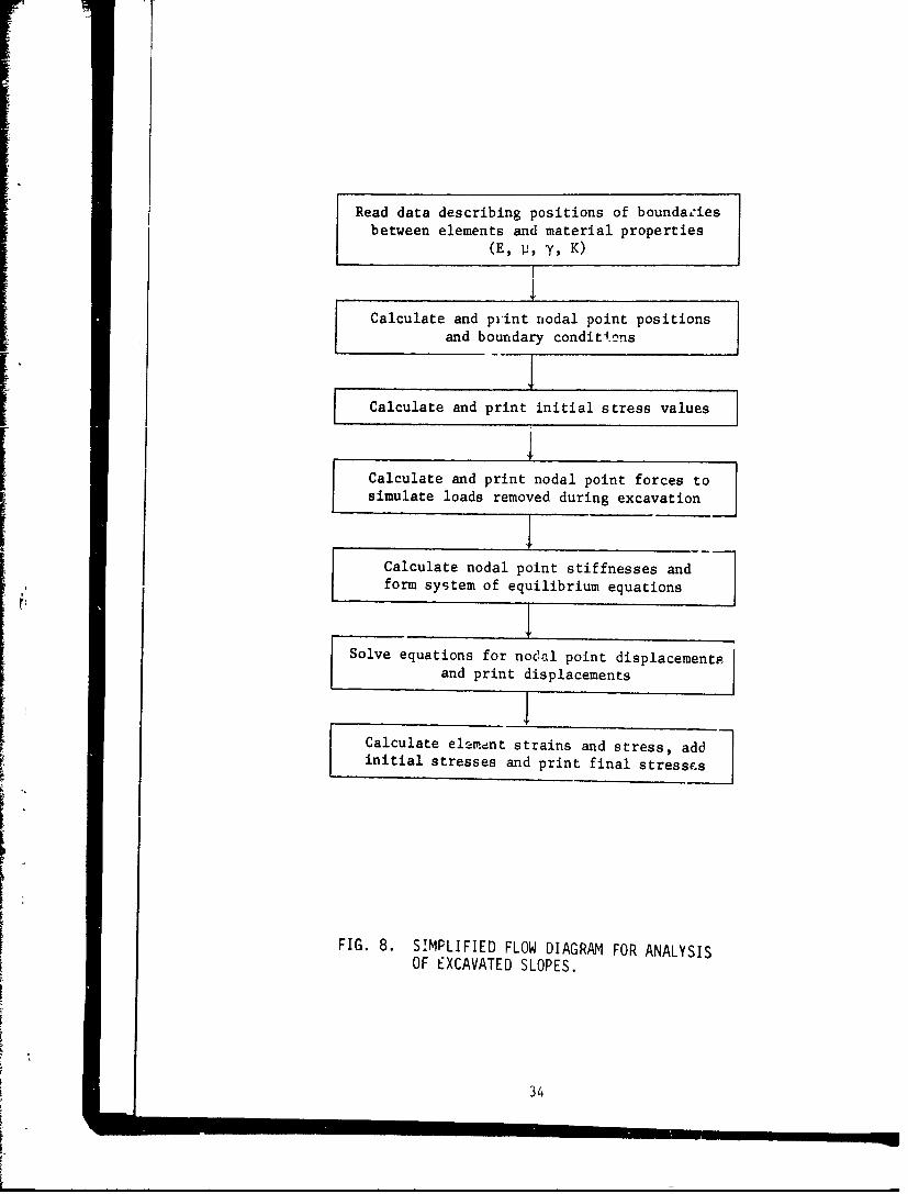
The operation of the computer program used in these analyses is
illustrated by the simplified flow diagram shown in Fig. 8. Data
describing the positions of the element boundaries, the initial stresses,
and material properties serve to define the problem. From these data
the computer proglam calculates nodal point coordinates and assigns
appropriate boundary conditions. Initial stress values for each element
are calculated using equations 2 and 3a, and nodal point forces are
calculated which represent the .tatic equivalents of the changes in
stress required to simulate the excavation process. The unit weight, y,
and the value of earth pressure coefficient, K, were assumed to be
constant; thus the initial horizontal and vertical stresses increased
linearly with depth. From the geometry of the elements, their values of
Young's modulus, E, and Poisson's Ratio, 11, the stiffness of each
element in the system iF next evaluated. The program used is formulated
for plane strain analyses, which closely simulates the behavior of slopes
having large long.tad-inal extent. The slopes analyzed were assumed to be
homogeneous with ,-,,spect to value of Young's modulus, and the value of
Poisson's Ratio wi assumed to be 0.475, a value appropriate to represent
a saturated -lay .Ath low bulk compressibility. For slopes in materials
which are homogeneous with respect to the value of Young's modulus, the
stresses calculaced are independent of the value of E used in the
computations.
From the boundary conditions, the loads, and the stiffnesses of
each nodal point, a system of equations (2 for each nodal point) is written,
expressing the nodal noint displacements in terms of the stiffnesses and
33
Read data describing positions of boundaziesbetween elements and material properties
(EP I!$ y, K)
Calculate and print nodal point positionsa.nd boundary conditions
Calculate and print initial stress values I
S Calculate and print nodal point forces to
simulate loads removed during excavation
Calculate nodal point stiffnesses andform system of equilibrium equations
Solve equations for nodal point displacementpand print displacements
ICalculate element strains and stress, addinitial stresses and print final stresses
FIG. 8. SIMPLIFIED FLOW DIAGRAM FOR ANALYSISOF EXCAVATED SLOPES.
34

the applied loads. This system of equilibrium equations is then solved
for the unknown nodal point displacements. Subsequently the strains and
stresses within each element are evaluated, and the changes in stress
are added to the initial stresses to determine the final state of stress
in each element.
Although stresses were calculated for each element and displacements
were calculated for each nodal point, only those in the immediate region
of the slope are considered in the ensuing discussion. The boundaries of
the regions considered are shown in Fig. 9; within these regions the
stresses are influenced to a negligible extent by the lateral boundaries,
and the results are thus representative of slopes in a clay layer of very
large lateral extent.
The post-excavation stress orientations are shown in Figs. 10 and 11;
the major principal stress direction indicated by the longer of the two
lines forming each cross; the lengths of the lines do not indicate the
stress magnitudes. The final stress orientations are dependent to .
large degree on the value of the earth pressure coefficient, K. A value
of K less than unity represents an initially vertical orientation of the
major principal stress, and K greater than unity represents an initially
horizontal orientation. The final streEs orientations are similarly
more nearly vertical for K = 0.81 than for K = 1.60. In each case shown,
the major principal stresses are oriented approximately vertically near
the surface behind the crest of the slope regardless of the value of K.
In the cases in which ttie slopes have not been cut to the rigid base, the
major princiial stresses are oriented approximately horizontally near the
bottom of the ctt in front of the toe of the slope. Comparing the
orientations for the two vertical slope configurations analyzed, it may
be noted that the major principal stress direction is more nearly
horizontal near the elevation of the toe of the slope for those cases
in which the slope is cut completely to the rigid base, indicating
larger shear stresses on the horizontal plane as a result of increased
rigidity at this level.
The deformed shapes of the slopes after excavation are shown in
Fig. 12. Each of the diagrams in Fig. 12 is plotted to the same dimension-
less scale in wnich the unit of measure shown in the figure is yH2 /E,
35

3H
H REGIO SHOW
77I TES LT
H
3~: SLOPE
h3H 15_I6H
H VERTGCOL SLOPE
R G IN STRESS PLOTS
L HL 6HOW
~~~VERTICAL SLOPEORGDBS
FIG. 9. BOUNDARIES OF REGIONS SHOWN IN STRESS PLOTS.
36

0
0 C'4
-MU
X Z
0'.0 kkL*II ~ l 1 ~
4
LU~Ct.
m H-
71 z
Hx
NLUQ
0
37

HlId30 Hld30
00
4- 4-
'0
o LA.
C 4r
4- - I
In0 I
00
Hl3 Hld30
x Ln
0
0LL -4- -4- -4-- **- 4 -~~= ~
V) -j
____ K X& 5;
38

0<
LL-J
0 CA
(DA
too
39i'ILC

indicating that the magnitudes of the slope displacements are proportional
to the unit weight and the square of the slope height, and inversely pro-
portional to the modulus value. For a slope 50 ft high excavated in soil
with unit weight of 100 lb/ft 3 and modulus value of 250,000 ib/ft2 , the
scale shown in Fig. 12 represents a distance of 1 ft. For a slope
25 ft high in the same soil, the scale represents 0.25 ft. it oay be
noted that selection of a single modulus value to characterize the
deformation of a large soil mass is very difficult. Therefore accurate
prediction of the magnitude of slope displacements is equally difficult,
because the displacements are inversely proportional to the modulus value.
The displacements shown in Fig. 12 for the vertical slope cut to a
rigid base are proportional to the value of the earth pressure coefficient
K. For the other slopes show.., which are not cut to the rigid base, the
displacements are in each case larger for the larger value of K, but are
not proportional to K.
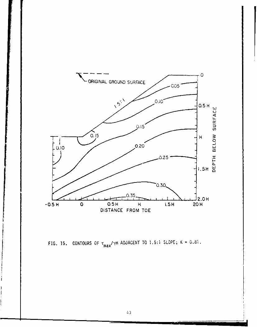
Contours of normalized shear stress, T max/yH, for the slopes analyzed
are shown in Figs. 13 through 20. The value of K has a very significant
effect on the magnitudes of the shear stresses after excavation. For each
of the four slope configurations studied, the largest value of T max/YH is
much higher for K = 1.60 than for K = 0.81, indicating that the stress
conditions around excavations in heavily overconsolidated clays are more
severe than around excavations of equal size in normally consolidated
clays.
In many normally consolidated clays both undrained shear strength
and modulus values increase with depth beneath the surface, and some
variation of modulus with depth may also be typical of overconsolidated
clays. To investigate the effect of modulus variation with depth,
analyses have been performed using modulus values increasing linearly
with depth from zero at the surface, and using modulus values constant
over a range of depth near the surface and then increasing with depth
as would be appropriate for a desiccated crust overlying normally
consolidated clay. These analyses showed that when the modulus increases
with depth, the shear stress values increase somewhat near the base of
the layer, but are not very much different from those calculated assuming
uniform modulus throughout the layer. Therefore, the contours shown in
40

cc
C)
in/
C\j CDin uj
CQ 0
0 0 0-0 re) c
< UU.
00
z -n
zzo C)
00
z 0
0 IO
-0
41

33V~fls M0-139 Hid3O
0 0
0
00
00
00
0:CC,)
0
-
z, Lnr. 0 0Z0 CD)
00
<D 00
00
I IN
000d
0L
42
-k - - -0
ORIGINAL GROUND SURFACE
u-
U,
0
2a0
-0.58H 0 O.5H H 1.5H 208HDISTANCE FROM TOE
FIG. 15. CONTOURS OF T max /yH ADJACENT TO 1.5:1 SLOPE; K 0.81.
43

0A
-N ORIGINAL GROUND SURFACE
0.00
-
0 O.5H HI.0H.20
DISTANC FRMHO
~~I ~. CNTURSOF ma/y AD~t±raTOL5: SOPE K= 160
Q4

N - - - - .0
TORIGINAL GROUND 0.05
0.1
0.2
-0.5 H
0.25
0.40OZ
.50
j 015 03
O-H0 0.5 H H
DISTANCE FROM TOE
FIG. 17. CONTOURS OF Ta/yH ADJACENT TO VERTICAL SLOPE; K *0.81.
45

ORIGINAL GROUND 0.05SURFACE 0.10
0.20.
0.25 Oj
0. ii0.40u
-0.055 0 L5-2
4.6

ORIGINAL GROUND SURFACE
- -. p II I I0
0.050.10
0-.15
U-
0.20 D
.05H
0.30
0.40
0o.50
.70 H0 O.5H H
DISTANCE FROM' TOE
FIG..19. CONTOURS OF Tmax /yH ADJACENT TO VERTICAL SLOPE CUT TO
RIGID BASE; K =0.81.
47

ORIGINAL GROUND SURFACE
L -0
0.05
0. 10
0.15/ uj
/0.20 r-
0.15 00000.10
0.5 H0
0.40
0.60
0.80
1.30
0 0.5 H
DISTANCE FROM TOE
FIG. 20. CONTOURS OF Tm /yH ADJACEMt 'lU VERTICAL SLOPE CUT TORIGID BASE; Ki 1.60.
48

Figs. 13 through 20 may be considered applicable to cases where the
modulus increases with depth, as well as to cases where the modulus is
approximately constant.
The largest value of 'r max/yH for each of the slopes shown in Fig. 13
through 20 are summarized in Table 2. The intensity of the shear stress
increases with increasing slope angle, and is more severe for the vertical
slope cut to the rigid base than for the vertical slope cut part-way to
the base, as would be expected. The values of shear stresses shown in
Table 2 for high initial horizontal stress vary between 171% and 224% of
the values for the same configurations with low initial horizontal stress.
The stress contours shown in Figs. 13 through 20 and the values listed in
Table 2 have been calculated using linear elastic theory, and would not
be expected to represent conditions for slopes in clay where local failure
and subsequent deformations have resulted in extensive redistribution of
stresses. It does seem logical to expect, however, that the stress values
would apply to sipes in clay with reasonable accuracy provided that the
shear stresses indicated are everywhere less than or equal to the shear
strength of the clay in which the slope is excavated.
The values of, T max/yH shown in Table 2 indicate that the stresses
around- excavated slopes in heavily overconsolidated clays might be much
more severe than those around slopes in normally consolidated clays. For
example, if a 3:1 slope 25 ft high were excavated in a 50 ft layer of
normally consolidated clay (K = 0.81) with unit weight of 100 lb/f t3 ,
the largest shear stress in the clay would be (0.31)(100)(25) - 775 lb/ft 2,
at the base of the layer. On the other hand, for the same slope in a
heavily overconsolidated clay (K = 1.60) with the same unit weight, the
largest shear stress would be (0.70)(100)(25) = 1750 lb/ft2 , also at the
base of the layer. Thus the maximum shear stress in the overconsolidated
clay would be more than twice as great as that in the normally consolidated
clay, as a result of the higher values of initial horizontal stress.
Values of stability coefficient, Su/YH, in which Su is the undrained
strength, have been calculated for the slopes analyzed using two different
methods-' and are listed in Table 3. Those listed in the column headed
"largest shear stress" are the values of Tmax/YH shown in Table 2, and
represent the strength required to prevent failure at all except a single
v4 49

TABLE 2. VALUES OF T a/yri FOR EXCAVATED SLOPESmax
Largest ValueSlope K of T max/yH Location
0.81 0.31 Base3:1
1.60 0.70 Base
0.81 0.36 Base1.5:1
1.60 0.78 Toe
0.81 0.57 ToeVertical
1.60 1.01 Toe
Vertical Cut 0.81 0.77 Toe
to Rigid Base .60 1.32 Toe
50

TABLE 3. VALUES OF S /yH FOR EXCAVATED SLOPES
S /YHUr
Slope K RatioLargest Average
Shear Stress Shear Stress
0.81 0.31 0.16 1.943:1 - -_ __ _
1.60 0.70 0.16 4.37
0.81 0.36 0.175 2.06
1.5:1 --
1.60 0.78 0.175 4.45
0.81 0.57 0.26 2.19
Vertical -
1.60 3.01 0.26 3.89
0.81 0.77 0.26 2.96Vertical Cut
to Rigid Base 1.60 1.32 0.26 5.07
51

location within the slopes. Those listed in the column headed "average
shear stress" were determined from Taylor's (38) slope stability charts
for 0 = 0, and therefore represent the stLe-gth required for equilibrium
along the most critical circular arc, assuming the soil has plastic stress-
strain characteristics. The ratio of the values of Su /yH determined by
the two methods are also shown in the table. The values of the ratio
shown in Table 3 represent the factor of safety, calculated by the
"ou = 0" method, for which failure would develop at one location within
the clay layer. For the analyses representing excavations in normally
consolidated clays the values of factor of safety corresponding to the
onset of failure range from about 2.0 to 3.0, and for the analyses
representing heavily overconsolidated conditions, they range from about
4.4 to 5.1. Therefore it may be seen that the factor of safety corres-
ponding to failure at a single location depends on the initial stress
conditions, the slope inclination, and the rigidity of the material at
the base of the excavation.
For a completely brittle soil or rock, which lost all shear resistance
after failure, it would be appropriate to design against failure at any
location within the slope. This procedure would require factors of safety
(by the equilibrium method of analysis) as high as 5.1 for the most
critical case shown in Table 3. For soils which do not suffer complete
lojs of shear resistance after failure however, it is not necessary to
prevent failure at all locations to insure overall stability of the slope;
smaller factors of safety have been successfully used for many slopes.
Although it may not be necessary to preven- failure completely, it may be
appropriate to recognize the influences of initial stress conditions and
stress-strain characteristics by employing higher factors of safety in
cases where these factors exert the most significant influence--fir
slopes in heavily overconsolidated stiff-fissured clays.
CONCLUSIONS
Many well-documented case histories show that the instability of
slopes in stiff-fissured clays and shales often cannot be explained in
terms of peak strength values determined by laboratory tests and
equilibrium methods of stability analysis. These case histories include
52
failures of embankment foundations, excavations, and natural slopes, and
encompass failures during construction as well as many years later,
Studies of the properties of heavily overconsolidated clays and
shales have disclosed a number of factors which may contribute to the
difference between peak laboratory strength values and the shear
resistance which can be mobilized in-situ. The initial stresses in
overconsolidated clays and shales may also adversely influence the post-
construction stresses and the stability of slopes. Field and laboratory
studies of the stresses in heavily overconsolidated clays and shales
show that, they are characterized by large horizontal stresses, and thus
have a greater tendency for lateral rebound than normally consolidated
clays.
Analyses of the stress conditions around excavated slopes described
herein indicate that the initial horizontal earth pressures have a con-
siderable influence on the magnitudes of shear stresses following construc-
tion. Shear stresses around excavated slopes are much larger for conditions
representing a heavily overconsolidated clay (high initial horizontal
stresses) than for conditions representing a normally consolidated clay
(low initial horizontal stresses). The results indicate that shear
stresses large enough to cause failure may develop at some points within
the slopes, even though the factor of safety according to the usual Ou 0
method is considerably greater than unity. The higher the horizontal
stresses before construction, the higher the factor of safety correspond-
ing to development of local failure around the slope. Therefore it would
be expected, as Bjerrum has suggested, that the existence of high hori-
zontal stresses in heavily overconsolidated clays and shales increases
the probability of progressive failure in these materials.
53

iAPPENDIX I - REFERENCES
1. Beene, R. R. W. (1967) "Waco Dam Slide," Journal of the Soil Mechanics
and Foundations Division, ASCE, Vol. 93, No. SM4, pp. 35-44.
2. Bishop, A. W. (1948) "Some Factors Involved in the Design of a LargeEarth Dam in the Thames Valley," Proceedings of the 2nd InternationalConference on Soil Mechanics and Foundation Engineering, Vol. 2, p. 13.
3. Bishop, A. W. (1955) "The Use of the Slip Circle in the StabilityAnalysis of Slopes," Geotechnique, Vol. 5, pp. 7-17.
4, Bishop, A. W. and Henkel, D. J. (1957), "The Measurement of SoilProperties in the Triaxial Test," London, Arnold.
5. Bishop, A. W. and Bjerrum, L. (1960) "The Relevance of the TriaxialTest to the Solution of Stability Problems," Proceedings of the ASCEResearch Conference on the Shear Strength of Cohesive Soils, Boulder,pp. 437-501.
6. Bishop, A. W. (1966) "The Strength of Soils as Engineering Materials,"Geotechnique, Vol. 16, No. 2, pp. 91-128.
7. Bjerrum, L. (1967) "Progressive Failure in Slopes of OverconsolidatedPlastic Clay and Clay Shales," Journal of the Soil Mechanics andFoundations Division, ASCE, Vol. 93, No. SM5, pp. 1-49.
8. Brooker, E. W. and Ireland, H. 0. (1965), "Earth Pressures at RestRelated to Stress History," Canadian Geotechnique Journal, Vol. 2,No. 1, pp. 1-15.
9. Brooker, E. W. (1967) "Strain Energy and Behavior of OverconsolidatedSoils," Canadian Geotechnical Journal, Vol. 4, No. 3, pp. 326-333.
10. Brown, C. B. and King, I. P. (1966) "Automatic Embankment Analysis:Equilibrium and Instability Conditions," Geotechnique, Vol. 16,No. 3, pp. 209-219.
11. Casagrande, A. and Wilson, S. D. (1952) "Effect of Rate of Loadingon Strength of Clays and Shales at Constant Water Content,"Geotechnique, Vol. 2, pp. 251-263.
12. Clough, R. W. (1960) "The Finite Element Method in Plane Stress Analysis,"Proceedings of the 2nd ASCE Conference on Electronic Computation,
Pittsburgh, Pa.
13. Clough, R. W. (1965) "The Finite Element Method in Structural Mechanics,"Chapter 7 of Stress Analysis, edited by Zienkiewicz and Hollister,John Wiley and Sons, London.
54

14, -Clough, R. W. and Woodward, R. .1., 1.LI (1967) "Analysis of Embankment
Stre~ses and Deformationn," Journal of the Soil Mechanics and Foundations
Division, ASCE, Vol. 93, No. SM4, pp. 529-549.
15. Duncan, J. M. and Seed, II, B. (1966) "Anisotropy and Stress Reorienta-
tion Effects in Clays," Journal of the Soil Mechanics and Foundations
Divfsion, ASCE, Vol. 92, No. SM5, pp, 21-50.
16. Finn, W. D. L. (1967) "Static and Dynamic Behavior of an Earth Dam,"
Canadian Geotechnical Journal, Vol. 4, No. 1.
17, Finn, W. D. L. (1966) "Static and Seismic Analysis of Slopes," Journal
of the International Society of Rock Mechanics--Rock Mechanics and
Engineering Geology.
I. Finn, W. D. L. (1966) "Static and Dynamic Stresses in Slopes," Proceedings
of the lot International Congress on Rock Mechanics.
19. Hansen, J. B. (1962) "Relationships between Stability Analyses with
Total and with Effective Stresses," Sols-Soils, Vol. 3, pp. 28-39.
20. Henkel, D. J. and Skempton, A. W. (1955) "A Landslide at Jackfield,
Shropshire, in a Heavily Overconsolidated Clay," Geotechnigue, Vol. 5,
No. 2, pp. 131-142.
21. He nkel, D. J. (1957) "Investigation of Two Long-Term Failures in London
Clay Slopes at Wood Green and Northolt," Proceedings of the 4th Inter-
national Conference on Soil Mechanics and Foundation Engineering, Vol. 2,
pp. 315-320.
22. Herrmann, H. G. and Wolfskill, L. A. (1966) "Residual Shear Strength of
Weak Shales," Report 5 of Waterways Experiment Station Technical Repoit
3-699," Engineering Properties of Nuclear Craters."
23. Hirschfeld, R. C., Whitman, R. V., and Wolfskill, L. A. (1965) "Review
and Analysis of Available Information on Slopes Excavated in Weak Shales,"
Report 3 of Watetways Experiment Station Technical Report 3-699,"
Engineering Properties of Nuclear Craters."
24. Kenney, T. C. (1963) "Stability of Cuts in Soft Soils," Journal of the Soil
Mechanics and Foundations Division, ASCE, Vol. 89, No. SM5, pp. 17-37.
25. Kjelklman, W. (1936) "Report on an Apparatus for Consumate Investigation of
the Mechanical Properties of Soils," Proceedings of the 1st International
Conference on Soil Mechanics and Foundation Engineering, Vol. 2, pp. 16-20.
26. Langer, K. (1963) Discussion of Field Observations Reported by K. Terzaghi,
Proceedings 1st International Conference on Soil Mechanics and Foundation
Engineering, Vol. 3, pp. 152-155.
27. Peterson, R. (1955) Closure to discussion of Proc. Paper 476 "Studies of
Bearpaw Shale at a Damsite in Saskatchewan," by R. Peterson; Proceedings
Paper No. 759, pp. 1-2.
28, Peterson, R. , Iverson, N. L, and Rivard, P. J. (1957) "Study of Several
Dam Failures on Clay Foundations," Proceedings of the 4th International
Conference on Soil MechAnics and Foundation Engineering, Vol. 2, p. 348.
- 55

14. ClUbugh, R. W. and Woodwurd, R. 1., II (1967) "Analysis of EmbankmentStresses and Deformations," Journal of the Soil Mechanics and FoundationsDivision, ASCE, Vol. 93, No. SM4, pp. 529-549.
15. Duncan, J. M. and Seed, 11. B. (1966) "Anisotropy and Stress Reorienta-tion Effects in Clays," Journal of the Soil Mechanics and FoundationsDivision, ASCE, Vol. 92, No. SM5, pp. 21-50.
16. Finn, W. D. L. (1967) "Static and Dynamic Behavior of an Earth Dam,"Canadian Geotechnical Journal, Vol. 4, No. 10
17. Finn, W. D. L. (1966) "Static and Seismic Analysis of Slopes," Journalof the International Society of Rock Mechanics--Rock Mechanics andEngineering Geology.
1i. Finn, W. D. L. (1966) "Static and Dynamic Stresses in Slopes," Proceedingsof the 1st International Congress on Rock Mechanics.
19. Hans-en, J. B. (1962) "Relationships between Stability Analyses withTotal and with Effective Stresses," Sols-Soils, Vol. 3, pp. 28-39.
20. Henkel, D. J. and Skempton, A. W. (1955) "A Landslide at Jackfield,Shropshire, in a Heavily Overconsolidated Clay," Geotechnique, Vol. 5,No. 2, pp. 131-142.
21. Honkel, D. J. (1957) "Investigation of Two Long-Term Failures in LondonCl+ay Slopes at Wood Green and Northolt," Proceedings of the 4th Inter-national Conference on Soil Mechanics and Foundation Engineering, Vol. 2,pp. 315-320.
22. Herrmann, H. G. and Wolfskill, L. A. (1966) "Residual Shear Strength ofWeak Shales," Report 5 of Waterways Experiment Station Technical Report3-699," Engineering Properties of Nuclear Craters."
23. Hirschfeld, R. C., Whitman, R. V., and Wolfskill, L. A. (1965) "Reviewand Analysis of Available Information on Slopes Excavated in Weak Shales,"Report 3 of Waterways Experiment Station Technical Report 3-699 ,"Engineering Properties of Nuclear Craters."
24. Kenney, T. C. (1963) "Stability of Cuts in Soft Soils," Journal of the SoilMechanics and Foundations Division, ASCE, Vol. 89, No. SM5, pp. 17-37.
25. Kjellman, W. (1936) "Report on an Apparatus for Consumate Investigation ofthe Mechanical Properties of Soils," Proceedings of the lst InternationalConference on Soil Mechanics and Foundation Engineering, Vol. 2, pp. 16-20.,
26. Langer, K. (1963) Discussion of Field Observations Reported by K. Terzaghi,Proceedings 1st International Conference on Soil Mechanics and FoundationEngineering, Vol. 3, pp. 152-155.
27. Peterson, R. (1955) Closure to discussion of Proc. Paper 476 "Studies ofBearpaw Shale at a Damsite in Saskatchewan," by R. Peterson; ProceedingsPaper No. 759, pp. 1-2.
28, Peterson, R., Iverson, N. L. and Rivard, P. J. (1957) "Study of SeveralDam-Failures on Clay Foundations," Proceedings of the 4th InternationalConference on Soil Mechanics and Foundation Engineering, Vol. 2, p. 348,
55
m

29. Peterson, R., Jaspar, J. L., Rivard, P. 1. and Iverson, N. L. (1960)"Limitations of Laboratory Shear Strength in Evaluating Stability ofHighly Plastic Clays," Proceedings of the ASCE Research Conferenceon the Shear Strength of Cohesive Soils, Boulder, pp. 765-791.
30. Sevaldson, R. A. (1956) "The Slide in Lodalen, October 6th, 1S54,"Geotechnique, Vol. 6, No. 4, pp. 167-182.
31. Sherif, M. A. and Chen, J. T. (1967) "Application of the Finite-Element Method to Stress Distribution in Soil Media," QuarterlyJournal of the University of Washington, College of Engineering,October, 1967.
32. Skempton, A. W. (1945) "A Slip in the West Bank of the Eau Brink Cut,"Journal of the Institution of Civil Engineers, Vol. 24, No. 7,pp. 267-287.
33. Skempton, A. W. (1948) "The i 0 Analysis of Stability and ItsTheoretical Basis," Proceeding. of the 2nd International Conferenceon Soil Mechanics and Foundation Engineering, Vol. 1, pp. 145-150.
34. Skempton, A. W. (1961) "Horizontal Stresses in an OverconsolidatedEocene Clay," Proceedings of the 5th International Conference onSoil Mechanics and Foundation Engineering, Vol. 1, pp. 351-357.
35. Skempton, A. W. and Brown, J. D. (1961) "A Landslide in BoulderClay at Selset, Yorkshire," Geotechnique, Vol. 11, No. 4, pp. 280-293.
3t). Skempton, A. W. (1964) "Long-term Stability of Clay Slopes,"Geotechnigue, Vol. 14, No. 2, pp. 77-102.
37. Skempton, A. W. and LaRochelie, P. (1965), "The Bradwell Slip: A Short-term Failure in London Clay," Geotechnigue, Vol. 15, No. 3, pp. 221-241.
38. Taylor, D. W. (1948) Fundamentals of Soil Mechanics, John Wiley & Sons,New York.
39. Terzaghi, K. (1936) "Stability of Slopes in Natural Clay," Proceedingsof the 1st International Conference on Soil Mechanics and FoundationEngineering, Vol. 1, pp. 161-165.
40. Van Auken, F. M., (1963) "Shear Strength of Clay-Shales Found in theSouthwestern U.S.A." Proceedings of the 2nd PanAmerican Conferenceon Soil Mechanics and Foundation Engineering, Vol. 1, pp. 255-287.
41. Ward, W. H. (1957) Discussion, Proceedings of the 4th InternatiGnalConference on Soil Mechanics and Fuundation Engineering, Vol. 3,pp. 123-124.
42. Ward, W. H,, Samuels, S. G. and Butler, M. E. (1959) "Further Studies ofthe Properties of London Clay," Geotechniue, Vol. 9. No. 2, pp. 33-58.

43, Whitman, R. V. and Bailey, W. A. (1967) "The Use of Computers forSlope Stability Analysis," Journal of the Soil Mechanics andFoundations Division, ASCE, Vol. 93, No. SM4, pp. 475-498.
44. Wilson, E. L. (1963) "Finite Element Analysis of Two DimensionalStructures," Thesis presented to the University of California,Berkeley, in partial fulfillment of the requirements for the degreeof Doctor of Philosophy.
57

DISTRIBUTION LIST
No. ofAddress Copies
Office, Chief of Engineers, Department of the ArmyATTN: ENGCW-ES 3
ENGAS-I 1
Each CE DivisionATTN: Chief, Geology, Soils, and Materials Branch, Engineering 2
Division
Director, U. S. Army Engineer Nuclear Cratering Group 1ATTN: NCG-ESLawrence Radiation LaboratoryP.O. Box 808, Livermore, Calif. 94550
District Engineer, U. S. Army Engineer District, Jacksonville 1ATTN: SAJGI
Mr. George E. Bertram 14701 Kenmore Ave., Apartment 819Alexandria, Va. 22304
Mr. Stanley D. Wilson 11105 North 38th St.Seattle, Wash. 98103
Prof. Arthur CasagrandePierce Hall, Harvard UniversityCambridge, Mass. 02138
Mr. John Lowe IIITippett s-Abbett-McCarthy-Stratton375 Park Ave.New York, N. Y. 10022
Prof. Ralph B. Peck 1Department of Civil EngineeringUniversity of IllinoisUrbana, Ill. 61801
Prof. Steve J. Poulos 1Pierce Hall, Harvard UniversityCambridge, Mass. 02138
Prof. Ronald C. Hirschfield 1Room 1-330Massachusetts Institute of TechnologyCambridge, Mass. 02139
1

No. of
Address os
Prof. H. Bolton SeedDepartment of Civil EngineeringUniversity of CaliforniaBerkeley, Calif, 94720
Prof. James Michael Duncan
Department of Civil EngineeringUniversity of CaliforniaBerkeley, Calif. 94720

UnclassifiedS c*tv C4 $4 sgfcto
DOCUIMENT CONTOOL DATA.- N & 0(seueesat~ o.ticuati.. of fil. b.4 a orc aM4 ' I alWWII amnestsmon swa be smeared whom 0M. l F"01 rrto as ea diE
1. ORIGINATING6 ACIVT (V6"nfi -p W S&i N1POfRY WCUROTT CLASSIPICAT1001
College of Engineerng, VOffice of Research Services UnclassifiedUniversity of California, Berkeley, Calif. js mu
3. "tPONT TITL9
SLOPES IN STIFF-FISSURED CLAYS AM~ SHALES
4 Ou11CmIPTIVS NOT 9S (rpof a# NOW and Inulow$V. deft#)
Final report1. AU THOAMIII no"m, fiiW $0100, taut mtaftl
James M,. DunoanPeter Dunlop
4. ~~SPONT OATS 10~". TOTAL NO. OF AE b O ump
kCONYNC GAT No / Va.ORSIIATOR'S ORPORT U1111010010DA-22.O79-CIVEdfG-62-47 Iv/
6. PROJECT NO. Report No. TE 68-6
a. Sb. 3j;EA mE~~~~~~~RPOPvNII(u a beaSlarS .. sFWQU. S. Army Engineer Waterways
________________________________Experiment Station Contract Report s-68-?4
This document has been approved for public release and sale, its distributionis unlimited.
It. 6161011.910NTARY NOas Is. 11"sPontsON MILITARY ACTIVITY
U. S. Army Engineer Waterways Experiment______________________________ jStation, Vicksburg, Miss.
is A611TRACT
The objee-tivo of this invo stigrttion was to review existing information concerningf-lope failures in stiff, fissureI clays tnd sha2les, and to study the influence ofl'teral stresses on the stresr ronlitions around excavated slopes. These studies,drhir'h were performed using thu ',inite element method of analysis, show that theinitial horizontal pressurecs have a considerable influence on the magnitudes of2h-ar stresses following construction. Shear stresses arot~nd excavated slopes aremuch larg-r for conditions representative of heavily owerconsolidated clays (highInitial horizontal stresses) than for conditions representative of normally con-solidated clays (low initial horizontal stresses). Shear stresses large enoughto cause failure at some points may develop even when the factor of safety calculatedby the 0 - 0 method of analysis is much larger than unity. The higher the horizontalstresses bef~re excavatirm, the higher the factor of safety corresponding to the(levelopment of local fail ire.
DD I Now 6647 11211

SLWNM A LINK St LIWK C
0LO y WI OLK W SIOLe WT
ClaysShales
Shear stress
Slope failure
Unclassified