distibuted by: national technical information … types of fuels storage tanks and the distribution...
TRANSCRIPT

AD-AOll 588
DESIGN FOR CORROSION CONTROL OF AVIATIONFUEL STORAGE AND DISTRIBUTION SYSTEMS
Fred Reinhart
Civil Engineering Laboratory
Prepared for:
Air Force Weapons Laboratory
June 1975
DISTIBUTED BY:
National Technical Information ServiceU. S. DEPARTMENT OF COMMERCE

AFWL-TR-74-31 AFWL-TR-74-31
191137
OC DESIGN FOR CORROSION CONTROL OF
AVIATION FUEL STORAGE AND DISTRIBUTIONSYSTEMS
Fred Reinhart
O Civil Engineering Laboratory
Naval Construction Battalion CenterPort Hueneme, CA 93043
June 1975
Final Report for Period 15 October 1970 - 15 October 1974
Approved for public release; distribution unlimited.
VF DR.eP-d ...d by:-
NATIONAL TECHNICALINFORMATION SERVICE
US Qop.rine.t of Co,,m 1ceSp ogf,.Id, VA. 22151
AIR FORCE WEAPONS LABORATORYAir Force Systems CommandKirtland Air Force Base, NM 87117

UNCLASSIFIEDEC:t,'IT" CL ASSFI1 A TION OF rH I 1 AGw a'- fLe-errrd)
REPORT DOCUMENTATION PAGE ~ ~ II(MJ UiFRI REPORT 1.L~~dOER 27 GOVT ACCE SS'C'N NC. 3 P_ I T0CV_'_ iar
AFWL-TR-74-314 TIT TLE (and Subf'tleI T'IFE 3c REPORT A PERIOD ZOVERE,
fFinal Report for: 15 Oct 70DESIGN FOR CORROSION CONTROL OF AVIATION FUEL I
STORGE AD DITRIBTIONSYSTMS thru 15 Oct 74STORGE ND ISTIBUTON YSTMS PFkF NGG. PEPORT NUMBER
7 Au THOR(sI- ________- 8 CONIQACT OR GRANT NkUM.3CR,,
Fred Reinhart 'JON 21022C0Z
9 PER.'ORMING ORGANIZATION NAME AND ADDRESS _ -,V .EHT PR. 1JLC-, TAS:
Civil Engineering Laboratory -ora Elmet 63723FNT UMENaval Construction Battalion Center 'roram: Elmet: 6323Port Hueneme, CA 93043 arsec: 21011 CONTROLLING OFFICE NAME AND ADDRESS 12. REPORT DArb.
June 197513. 'I'VJMBEP OF PAGES
14 MONITORING AGENCY NAME & ADDRESS~of differnt from, Controlling Office) MS SECURITY CLAS5. (of this rep-r)
Air Force Weapons Laboratory UNCLASSIFIEDKirtland Air Force Base, NM 87117 IS. DECLASSIFICATION4 DOWNGRADING
SCHEDULE
16 DISTRIBUTION STATEMENT (of this Report)
Approved for public release; distribution unlimited.
17 D!STRIBUTION STATEMENT (of the abstract entered in Block 20, It different from Report)
Same as block 16.
IS SUPPLEMENTARY NOTES
1 EYWORDS rcontin,,e on reverse side it necess ary and identifsy by block numeber)
Civil Engineering Corrosion PreventionDesign TechniquesFuel Storage and Fuel Distribution
PRICES SUBJECT TO CWAGE20 ABSTRACT (Continue n reverse side If necevsary, and Iderntifv hr., olock nurnmlerl
An exhaustive review was made of th e literature on corrosion problems andtheir control as they pertain to aviation fuel storage and distribution systems.Information obtained is combined and presented in a manner suitable for use bydesigners responsible for new construction at the various US Air Force bases; itcovers the many corrosion-related variables encountered with respect to the dif-ferent types of fuels storage tanks and the distribution lines essential to sup-plying uncontaminated fuels to planes. Methods of reducing the corrosion of
DD 'iOA 1473 EDITION OF 1 NOVA1 S IS OBSOLETE _____ NCASFESECURITY CL. AS1,IPIATIc)N C.7 THIS PACE 0lI ,, )fta Foer,'

UNCLASSIFIEDr SECURITN CLASSIFICATION OF THIS PAGE(Wheb Date Entred)
metals used in these systems are considered by identifying potential cduses for
corrosion in the soil, other external environments to be encountered and in fuelthemselves. Different procedures to anticipate and control corrosion are pre-sented, including the use of protective coatings, cathodic protection, andplastics composites as a substitute for metals. Problem areas such as galvaniccorrosion, proper surface preparation and techniques for application of protec-tive coatings are considered. Guidelines are given that combine economic con-siderations with practical corrosion control procedures that will give the mostefficient service life compatible with a projected time-of-use requirement.
ii UNCLASSIFIEDSECURITY CLASSIFICATION OF THIS PAGEI' en Data Efered)
...M. . . . -L -- I

AFWL-TR-74-31
This final report was prepared by the Civil Engineering Laboratory, NavalConstruction Battalion Center, Port Hueneme, CA 93043, under Program Element63723F, Project 2102, Task 2, JON 21022CO2, with the Air Force Weapons Laboratory,Kirtland Air Force Base, New Mexico 87117. Lt Col Doctor S. Morrisey (AFCEC/OL-AA) was the Laboratory Project Officer-in-Charge.
When US Government drawings, specifications, or other data are used for anypurpose other than a definitely related Government procurement operation, the
Government thereby incurs no responsibility nor any obligation whatsoever, andthe fact that the Government may have formulated, furnished, or in any waysupplied the said drawings, specifications, or other data is not to be regardedby implication or otherwise as in any manner licensing the holder or any otherperson or corporation or conveying any rights or permission to manufacture, useor sell any patented invention that may in any way be related thereto.
This technical report has been reviewed and is approved for publication.
DOCTOR S. MORRISn , Lt Ctlonel, USAFProject Officer
FOR THE COMMANDER
REDERICK H. PEERSN WILLIAM B. LIDDICOET, Colonel, USAFAsst Chief, Aerospace Facilities Branch Chief, Civil Engineering Research Div
O NT RERN T PY.n O
DO NOT RETURN THIS COPY. RETAIN OR DESTROY.

iCORROSION CONTROL DESIGN FOR AVIATION FUEL
STORAGE AND DISTRIBUTION SYSTEMS
Page
SECTION I - Introduction . 1
SECTION II - Site Selection 1
1. Determination of Corrosivity 2
2. Engineering Considerations . 33. Operating Considerations 3
, 4. Economic Considerations 35. Maintenance Considerations 5
6. Safety Considerations . 6
SECTION III - Corrosion and Corrosion Control of
External Surfaces 7
1. Classification of Environment 72. Corrosion Control by Materials Selection 10
3. Corrosion Control by Alteration of the Environment 12
4. Corrosion Control by Protective Coatings , 125. Corrosion Control by Cathodic Protection 19
SECTION IV - Corrosion and Corroqion Control of
Internal Surfaces 23
1. Classification of Environment 23
2. Corrosion Control by Materials Selection 26
'. Corrosion Control by Protective Coatings 27Corrosion Control by Cathodic Protection 29
SECTION Specific Applications 29
1. Fuel 3torage Facilities 29
2. Fuel Distribution Systems 32
SECTION VI - Glossrry of Terms 37
SECTION VII - Bibliogr hy 51
iv

CORROSION CONTROL DESIGN FOR AVIATIUN
FUEL STORAGE AND DISTRIBUTION SYSTEMS
SECTION I
Introduction
1. Purpose. This technical report provides the latest design proce-dures for corrosion control of aviation fuel storage and distributionsystemL. Air Force Base construction, to achieve maximum protectionper construction dollar against corrosion and to avoid unnecessarycorrosion-caused breakdowns and later expenditures for corrosion control.
2. Scope. This technical report covers corrosion control procedures
for new construction of aviation fuel storage and distribution systems.It incudes storage facilities, pipeline mains, distribution systems,
fittings, manifold systems and portable systems (tank trucks). Thismanual will primarily concentrate on design procedures for metal butwill also consider plastics because they completely eliminate most corro-
sion problems.
3. Cost of Corrosion. Corrosion costs for the United States havebeen estimated at 20 to 30 billion dollars per year. Costs due to corro-
sion include:
a. Loss of plant equipment
b. Loss of product
c. Contamination of productd. Repair or replacement of equipment
e. Pollution of environment and attendant clean-up costsand/or fines.
f. Medical expenses due to injuries or loss of life.
g. Service interruptions.h. Deteriorated public relations.
In the past five to ten years many technical developments in the fieldof corrosion have occurred. To assess properly these developments and
their field applicability, a survey of the literature and of currentindustrial techniques for combating corrosion has been made. The findingsof this survey were used as a basis for the preparation of this report.
SECTION II
Site Selection
Site selection for aviation fuel storage should be based on, amongother things, environmental conditions which would lead to minimum corro-sion. Such factors as the corrosivity of the soil, the atmosphere, and
* Jamar, L. G., ''The Forgotten Phenomenon,'' Air Force Civil Engineer,
August 1972.
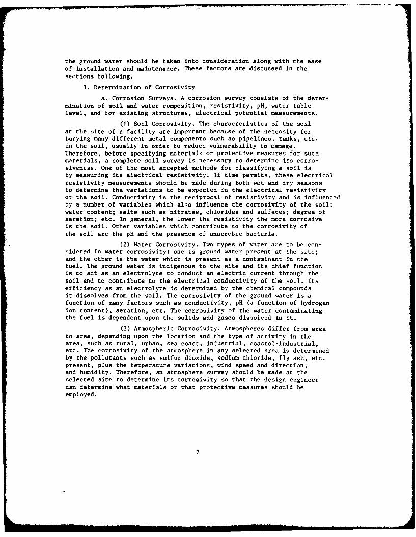
the ground water should be taken into consideration along with the easeof installation and maintenance. These factors are discussed in thesections following.
1. Determination of Corrosivity
a. Corrosion Surveys. A corrosion survey consists of the deter-mination of soil and water composition, resistivity, pH, water tablelevel, and for existing structures, electrical potential measurements.
(1) Soil Corrosivity. The characteristics of the soilat the site of a facility are important because of the necessity forburying many different metal components such as pipelines, tanks, etc.in the soil, usually in order to reduce vulnerability to damage.Therefore, before specifying materials or protective measures for suchmaterials, a complete soil survey is necessary to determine its corro-siveness. One of the most accepted methods for classifying a soil isby measuring its electrical resistivity. If time permits, these electricalresistivity measurements should be made during both wet and dry seasonsto determine the variations to be expected in the electrical resistivityof the soil. Conductivity is the reciprocal of resistivity and is influencedby a number of variables which alqo influence the corrosivity of the soil:water content; salts such as nitrates, chlorides and sulfates; degree ofaeration; etc. In general, the lower the resistivity the more corrosiveis the soil. Other variables which contribute to the corrosivity ofthe soil are the pH and the presence of anaerubic bacteria.
(2) Water Corrosivity. Two types of water are to be con-sidered in water corrosivity: one is ground water present at the site;and the other is the water which is present as a contaminant in thefuel. The ground water is indigenous to the site and its chief functionis to act as an electrolyte to conduct an electric current through thesoil and to contribute to the electrical conductivity of the soil. Itsefficiency as an electrolyte is determined by the chemical compoundsit dissolves from the soil. The corrosivity of the ground water is afunction of many factors such as conductivity, pH (a function of hydrogenion content), aeration, etc. The corrosivity of the water contaminatingthe fuel is dependent upon the solids and gases dissolved in it.
(3) Atmospheric Corrosivity. Atmospheres differ from areato area, depending upon the location and the type of activity in thearea, such as rural, urban, sea coast, industrial, coastal-industrial,etc. The corrosivity of the atmosphere in any selected area is determinedby the pollutants such as sulfur dioxide, sodium chloride, fly ash, etc.present, plus the temperature variations, wind speed and direction,and humidity. Therefore, an atmosphere survey should be made at theselected site to determine its corrosivity so that the design engineercan determine what materials or what protective measures should beemployed.
2

*1b. Results of Operating Similar Systems in the Area. If there
are existing installations of a similar nature in the area, an evaluationof the operation of these installations should be made to determine equip-ment shutdowns, problems, or maintena-2e related to corrosion. Plant
operating records should be reviewed, where available. Weaknesses in corro-
sion design should be particularly noted as indicated by unplanned shutdownsor maintenance expenses. Particular attention should be paid to shutdownperiods and a determination of the causes of shutdown should be established.If the shutdowns are due to corrosion, then clearly, proper precautionsand corrosion control procedures should be taken into considerat'on. The
results of operating similar systems is perhaps the most valuable toolthat a corrosion engineer has. It should certainly not be overlookedwhen consideration is being given in design work to the type and extentof corrosion protection necessary to establish adequate corrosion control.
2. Engineering Considerations. Certain basic engineering designconsiderations should also be followed:
a. Design for easy cleaning and drainage.
b. Design for easy component replacement where service failure
is anticipated, e.g. modular construction design.c. Avoid high localized stress concentrations.
d. Avoid dissimilar metal contacts.e. Minimize or exclude air.f. Avoid heat transfer hot spots.g. Join by coutinuous welding rather than riveting.
h. Use smooth wide radius bends in piping systems.i. Avoid metallic contact with absorptive materials.
j. Avoid high velocities.
3. Operating Considerations. Operating conditions also play a rolein corrosion design requirements. Factors such as ambient temperature
and frequency of use should be considered. Continuous operations usually
result in less corrosion and less maintenance than with intermittentoperation where parts are left unattended or in a static condition forlong periods of time. Fuel flow through structures aids in the reductionof the amounts of water, corrosion products and deposits which canaccumulate in the system under static conditions and lead to acceleratedattack. For this reason, flow or continuous use is desirable, rather
than static conditions or intermittent use.
4. Economic Considerations. If the operating life required fora given installation is extremely short, then little or no corrosion
protection may be required. On the other hand, if the base is to be apermanent installation, it may be economical to expend the necessary
funds for design engineering and construction to obtain long-termcorrosion-free operation of base fuel systems.
In all construction work economic factors must be taken into consid-eration, including initial costs of the materials, construction, andfollow-on costs of maintenance. Follow-on costs for additional corrosion
3

protection may be high and must be taken into consideration when theoriginal design is considered. For example, adding additional anodesand rectifiers may cost 2 or 3 times as much as the cost of installingthe same equipment at the time of original construction.
a. Initial Costs. The initial costs will include the costsof the structure and the cost of corrosion protection established forthe structure. The choice of the material and the corrosion protectionsystem will depend on economic factors as well as on the design lifeof the structure. These in turn will be controlled by monetary fundsavailable, the desired life of the structure, and the nature of thesite where the construction is required.
b. Maintenance Cost During Estimated Service Life. In deter-mining what type of structure and corrosion protection should be designedto minimize corrosion, the estimated service life must be considered.Also, anticipated maintenance costs for the various structures, systems,and corrosion protection devices, over the estimated service life shouldbe such that the sum of original cost plus the maintenance costs isminimum per year of required service. For example, if a cathodic protectionsystem is being designed, great care should be exercised in the initialdesign to be sure that the system will provide the protective currentrequired not only initially but during later stages of operation withoutmajor redesign of the system. Protective current requirements usuallyincrease during the life of a system as a result of coating degradation.Additions to a cathodic protection system during the life of the systembecome very expensive when compared to initial costs. Replacing of anodebeds, or replacement of rectifiers with greater capacity is costly,and may be difficult after other adjoining structures are in place.Therefore, it is usually wise to allow for such contingencies in theoriginal design of the cathodic protection equipment. Often a figureof 2 to 3 times the initial current requirement is arbitrarily usedfor determining the size of the rectifiers and the anodes beds required.The same comments also apply to coating systems. The least expensiveoriginal coating system often will become the most expensive coatingsystem in terms of cost per square foot per year. It is therefore impor-tant that the engineer designing a cathodic protection or a coatingsystem consider not only initial cost but maintenance costs for thetime period it is estimated that the structure will be in use.
c. Direct Loss. Direct loss costs relate to replacement costsof the structure should the structure become inoperative or completelylost due to corrosion. Therefore, it should be borne in mind that thesereplacement costs can be minimized or eliminated by using the propermaterials in the original design. Once a structure is in place and otberbuilding or construction has taken place nearby, replacement may bemany times the original cost.
d. Indirect Loss. As the title indicates, indirect loss doesnot relate to the direct loss of the structure and replacement of theequipment involved, but relates to other losses involved in a corrosion
4
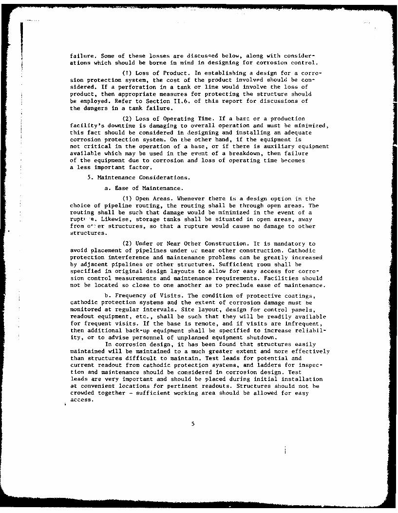
Ifailure. Some of these losses are discusged below, along with consider-ations which should be borne in mind in designing for corrosion control.
(I) Loss of Product. In establishing a design for a corro-sion protection system, the cost of the product involved should be con-sidered. If a perforation in a tank or line would involve the loss ofproduct, then appropriate measures for protecting the structure shouldbe employed. Refer to Section 11.6. of this report for discussions ofthe dangers in a tank failure.
(2) Loss of Operating Time. If a basc or a productionfacility's downtime is damaging to overall operation and must be minimized,this fact should be considered in designing and installing an adequatecorrosion protection system. On the other hand, if the equipment isnot critical in the operation of a base, or if there is auxiliary equipment
available which may be used in the event of a breakdown, then failureof the equipment due to corrosion and loss of operating time becomesa less important factor.
5. Maintenance Considerations.
a. Ease of Maintenance.
(1) Open Areas. Whenever there is a design option in thechoice of pipeline routing, the routing shall be through open areas. Therouting shall be such that damage would be minimized in the event of arupt, -e Likewise, storage tanks shall be situated in open areas, awayfrom o 'er structures, so that a rupture would cause no damage to otherstructures.
(2) Under or Near Other Construction. It is mandatory toavoid placement of pipelines under uL: near other construction. Cathodicprotection interference and maintenance problems can be greatly increasedby adjacent pipelines or other structures. Sufficient room shall bespecified in original design layouts to allow for easy access for corro-sion control measurements and maintenance requirements. Facilities shouldnot be located so close to one another as to preclude ease of maintenance.
b. Frequency of Visits. The condition of protective coatings,cathodic protection systems and the extent of corrosion damage must bemonitored at regular intervals. Site layout, design for control panels,readout equipment, etc., shall be such that they will be readily availablefor frequent visits. If the base is remote, and if visits are infrequent,then additional back-up equipment shall be specified to increase reliabil-ity, or to advise personnel of unplanned equipment shutdown.
In corrosion design, it has been found that structures easilymaintained will be maintained to a much greater extent and more effectivelythan structures difficult to maintain. Test leads for potential andcurrent readout from cathodic protection systems, and ladders for inspec-tion and maintenance should be considered in corrosion design. Testleads are very important and should be placed during initial installationat convenient locations for pertinent readouts. Structures should not becrowded together - sufficient working area should be allowed for easyaccess.
5

6. Safety Considerations.
a. Department of ' iansportation Regulations, Title 49, Chapter1. The book, 'Part 195 - Transportation of Liquids by Pipeline,'' pub-lished by the Office of Pipeline Safety in 1973. is the authority forthe safe transportation of liquids by pipeline. This document givesrequirements for the design, construction, operation and maintenance ofpipelines which carry liquid petroleum products. Sections 195.242, 195.244,195.414 and 195.416 pertaining to cathodic protection; 195.236 on externalcoating and 195.418 on internal corrosion control are particularly appli-cable to corrosion control design for aviation fuel distribution systems.
b. Location Re1tive to Personnel Density. Any fuel storagetank or pipeline should be located when possible so that tupture orcatastrophic corrosion failure would not endanger personnel.
c. Nature of Product Being Transported and Safety Requirements.Fuels pose a fire hazard and adequate precautions should be taken toprotect personnel and structures should corrosion failures or blowoutsoccur.
d. Design Specifications. For the above reasons, the designof fuel systems shall take into account the possibility of corrosion;and sufficient allowance should be made to prevent catastrophic failureduring the anticipated life of the facilities. The original design willalso take into account ease of application of remedial measures requiredduring the life of the structure to minimize corrosion.
e. Property and Personal Liability. When designing corrosionprotection systems the liabilities involvei should a failure occur mustalso be taken into consideration. These liabilities include propertyand personal liabilities. The personal liabilities would have to do withany personnel injuries. Property liability would include equipment lossand could also include ecological damage, such as pollution of the soilor washout damage. The possibilities of such losses due to corrosionfailure should be considered in designing for corrosion control.
f. Ecological Damage and Cleanup Expenses. Much emphasis hasbeen placed upon ecological considerations within recent years. For thisreason, in any corrosion design, attention should be paid to the ecologicalfactors involved in corrosion failure resulting in spillage of product,either from leaky pipelines, failed tanks, or other defective structures.With respect to tankage the costs involved in repairing washouts shouldalso be considered in corrosion design. Washouts become particularlydangerous when large-volume tankage or high.pressure fuel lines aresituated on high ground. The nearby downslopes are susceptible to seriousand costly erosion and pollution should failure from corrocion occur.
g. Harmful Effects on Personnel. The concentration of gasolinevapors that can be tolerated by humans is far below that required toproduce combustible or explosive mixtures with air, one-tenth of thisamount being harmful if inhaled for more than a short time. Moderate
6

amounts will cause dizziness, nausea, and headache; while large amountsact as an anesthetic and cause unconsciousness. All gasolines and hydro-carbon fuels as well as meyl alcohol must be regarded as toxic. Lead
poisonin, from the inhalation of vapors of gasoline treated with tetra-ethyl lead, while not tc be feared from inhalation of vapors given offfrom open containers in open areas, will occur if these vapors are inhaledover a long period in an inadequately ventilated enclosure. Some jet-engine fuels such as JP-7 contain sufficient gasoline or naphtha to
cause this fuel to be regarded as toxic, but do not contain tetraethyllead. Gasoline will cause s.vere burns if allowed to remain in contactwith the skin, particularly when the contact is maintained und r soakedclothing or gloves. Lead in gasoline is not absorbed through the skinto any important extent. However, methyl alcohol may be absorbed through
the skin in sufficient quantities to cause the general effects of inhala-tion as a vapor. Methyl alcohol also causes irritation of the skin byremoving natural skin oils, causing cracking of the skin. This increasesthe possibilities of infection. The danger to personnel from inhalation
of the product's vapors or external contact with the liquid is anotherreason why design deficiencies of facilities for handling these products
that increa the possibilities of spillage or the accumulation of vapors
from these products in confined areas must be avoided.
SECTION III
Corrosion and Corrosion Control of External Surfaces
This section is concerned with all external metallic surfaces whichare subjected to the corrosive variables of the environment. This includespipes, tanks, supporting structures and any metals exposed to the atmo-sphere or buried in the soil. There are two ways of combating corrosion
of these external surfaces: use materials which are insensitive tocorrosion or use prctective systems which if properly maintained willpreserve the materials for the required service life.
1. Classification of Environment. In order to design the facility
at the selected site for the maximum maintenance-free performance thecorrosion-inducing characteristics must be known; that is, identifyingthe aggressive characteristics of the atmosphere and the soil at thesite.
a. Atmosphere. The chenical composition of the components ofthe atmosphere should be determined. Non-marine rural atmospheres arevery seldom polluted and as a general rule are not considered corrosive.The amount of corrosion normally expected from rain, air and sunshine
is minimal.In coastal environments the atmosphere may be laden with sea
salts, the degree depcnding upon the direction of the prevailing windsand the proximity to the ocean. In this case the protective measurements
employed should be resistant to sea-salt air.
7

In industrial atmospheres the type of concentrations of thepollutan)s shoild be known to combat their corrosive effects effectively.Some of the more prevalent pollutants are sulfur dioxide (SO2) gas,sulfide gases, chlorides, and nitrates. In coastal-industrial sites thesea salts in addition to any industrial pollutants contribute to thecorrosivity of the atmosphere. In industrial sites the protective mea-sures have to be tailored to combat the particular pollutants.
b. Soil. Soils vary widely in their physical and chemicalcharacteristics which in turn affect their corrosivity towards metals.Soils consist essentially of four types of substances: mineral matter,organic matter, water, and air.
(1) Effect of Moisture. The moisture content of a soilgreatly affects its corrosivity because of the decrease in the resistivitywith Lhe increase in the moisture content up to a point near saturation.It should be pointed out that it is the ion content of the electrolyte(water) that determines the resistance to the flow of an electric current,which plays a part in underground corrosion.
(2) Effect of Aeration. In well-aerated. usually red oryellow soils, the iron compounds have been oxidized to the ferric stateFe(O 1)3 or Fe203 nH20. In poorly aerated soils with their low oxygencontent the soils are generally gray in color, indicating the presenceof reduced forms of iron. Anaerobic soils, which are often black in color,can contain iron sulfide.
Size of soil particles has a definite relation to aerationand ability of soils to retain moisture. Differences in size of soilparticles may cause the formation of concentration cells. Metals in well-aerated soils (larger soil particles, e.g.- loam) will be cathodic tometals in the finer soil particles of poorly aerated soils (e.g.- clay).
Aeration factors are those that affect the access ofoxygen and moisture to the metal and thereby affect the corrosion. Oxygencan either be from atmospheric sources or from the reduction of saltsor compounds in the soil. This oxygen may tend to stimulate or retardthe corrosion process, the quantity available being the controllingfactor. Oxygen when present in large quantities will form insolublecompounds at the anodic areas on a structure and thus retard corrosion.Oxygen when present in ordinary quantities will stimulate the corrosionprocess by being reduced at cathodic areas on a structure to form wateror hydroxyl ions (4H+ + 02 + 4e- - 2H20 or 02 + 2H20 + 4e- + 40H-). Inordinary quantities, oxygen may also combine with metal ions which havemigrated away from anodic areas on the structure. This combination furtherincreases the rate of corrosion. Oxygen when present in small quantities,or absent, will not affect the corrosion process, and corrosion willproceed at a minimum rate.
Some specific examples will illustrate the effect of well-aerated soils and poorly aerated soils. On large-diameter pipelines,unless proper backfill materials or procedures are used, the upper portionof the pipe often is in soil that is well aerated, whereas the lower
8
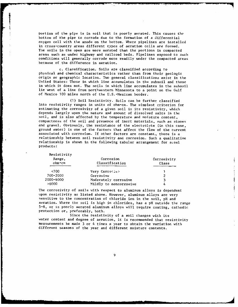
portion of the pipe is in soil that is poorly aerated. This causes thebottom of the pipe to corrode due to the formation of a differentialoxygen cell with the anode on the bottom. Where pipelines are installedin cross-country areas different types of aeration cells are formed.The soils in the open are more aerated than the portions in compactedareas such as under highway and railroad beds. Pipelines exposed to suchconditions will generally corrode more readily under the compacted areasbecause of the difference in aeration.
c. Classification. Soils are classified according tophysical and chemical characteristics rather than from their geologicorigin or geographic location. Two general classifications exist in theUnited States: Those in which lime accumulates in the subsoil and thosein which it does not. The soils in which lime accumulates in the subsoillie west of a line from northwestern Minnesota to a point on the Gulfof Mexico 100 miles north of the U.S.-Mexican border.
(1) Soil Resistivity. Soils can be further classifiedinto resistivity ranges in units of ohm-cm. The simplest criterion forestimating the corrosivity of a given soil is its resistivity, whichdepends largely upon the nature and amount of dissolved salts in thesoil, and is also affected by the temperature and moisture content,compactness of the soil and presence of inert materials, such as stonesand gravel. Obviously, the resistance of the electrolyte (in this case,ground water) is one of the factors that affect the flow of the currentassociated with corrosion. If other factors are constant, there is arelationship between soil resistivity and corrosion. Such a qualitativerelationship is shown in the following tabular arrangement for sLeelproducts:
ResistivityRange, Corrosion Corrosivityohm-cm Classification Class
<700 Very Corro-ii 1700-2000 Corrosive 22000-6000 Moderately corrosive 3>6000 Mildly to noncorrosive 4
The corrosivity of soils with respect to aluminum alloys is dependentupon resistivity as listed above. However, aluminum alloys are verysensitive to the concentration of chloride ion in the soil, pH andaeration. Where the soil is high in chlorides, has a pH outside the range5-8, or is poorly aerated aluminum alloys will require coating, cathodicprotection or, preferably, both.
Since the resistivity of a soil changes with itswater content and degree of aeration, it is recommended that resistivitymeasurements be made 3 or 4 times a year to obtain the variation withdifferent seasons of the year and different moisture contents.
9

d. Miscellaneous. There are several other factors orphenomena that are difficult to classify because they are a combinationof one or more of the previously mentioned causes of corrosion.
Bacterial action, another factor that influences undergroundcorrosion, is associated with aeration and the formation and presence ofsoluble salts. Bacteria are not only the simplest but also the mostnumerous forms of soil life. Certain forms, aerobes, thrive in the presenceof oxygen but other forms, anaerobes, function best in the absence ornear absence of oxygen. Each type of bacteria produces different chemicalproducts. For example, one type of bacterial action transforms sulfur-containing proteins and other organic combinations to hydrogen sulfideor elemental sulfur; and, if much air is available, these products aresubsequently oxidized to the sulfite and sulfate conditions (e.g.- sulfurousor sulfuric acid). However, the bacteria that have received the mostattention in studies of underground corrosion are the anaerobic bacteria,spirovibrio desulfuricans, which extract oxygen from the sulfate radicalto convert soluble sulfates to iron sulfide. It has been established thatsulfate-reducing bacteria occur in practically all soils throughoutthe world when moisture, sulfates, and assimilable organic and mineralmatter are present and oxygen is absent. Anaerobic bacterial action hasan effect on the corrosion of metals underground, principally becausesome of the products of bacterial action (H2 S and FeS) accelerate thenormal corrosion process.
2. Corrosion Control by Materials Selection. Generally, it is oftenmore economical to use materials which do not require protection ofany type. For example, a material possesses the necessary mechanicalproperties and also is uncorroded in the required environment, its useis preferred to that of a material which requires protection and canusually be justified if the required life is of sufficient length. Manytimes, the original cost of a corrodible material plus the cost of pro-tection and maintenance over the required life of the installation,will considerably exceed the original cost of a noncorrodible material.
a. Basis for Materials Selection. Materials selection shouldbe based upon the corrosiveness of the particular environment. Informationon the corrosiveness of this environment may be obtained in various ways.
(1) Similar Systems in the Area. At many sites or locationsinformation is available on the performance of materials being used insimilar applications. Usually the people in charge of such installationswill be glad to furnish performance data on the materials they are using,in addition to any satisfactory methods of protection. In these casesperformance data of materials and protective systems will be the mostreliable and should be used.
(2) Similar Systems in Similar Environments. Should infor-mation be unavailable such as that described above, then the availabilityof information from similar systems in similar environments should beinvestigated. In such situations the corrosive characteristics of the
10

atmosphere, soil, and ground water at the proposed site should be deter-mined. Then, with this basic information, the location of similar environ-ments with similar systems in operation should be investigated. Suchavailable and relatively reliable information should be used as a basisfor designing the system in question.
(3) Experimental Tests. If no reliable data are availableas described in paragraphs a(l) and (2) above, then the generation ofexperimental data may be necessary. If time permits, either field orlaboratory tests can be conducted to obtain approximate information. Iftime is not available, then the services of a consultant with wide exper-ience in the field in question should be engaged for guidance.
(a) Field Testing. Experimental data obtained byfield testing are often more reliable than laboratory testing becauseactual operating conditions can more readily be found there. However, itmust be emphasized that the actual environmental and operating conditionsmust be closely duplicated in experimental tests.
(b) Laboratory Testing. If laboratory testing mustbe done because of the time element, then the designer must be willingto accept the unreliability and disadvantages attendant on such tests.Laboratory tests are usually accelerated in some manner in order toobtain results within a shorter period of time. Some of the conditionswhich may be used to accelerate the test are elevated temperature,
increased humidity, increased velocity of flow, chemical solution tosimulate special environments, or increased chemical concentrations ofsolutions, or combinations of two or more of the above. These factorsusually increase the corrosion rates of materials and decrease the timerequired to obtain results. Also, in such laboratory tests, protectivecoatings may be caused to fail in shorter periods of time. Unfortunately,such tests very seldom duplicate the relative behavior obtained in servicefrom the same materials or protective coatings. Because of the lack ofcorrelation between laboratory tests with actual service performance,
such tests are seldom recommended as a source of reliable information.
They are, however, often useful as a ''screening process'' used toeliminate undesirable materials prior to field testing.
(4) Galvanic Corrosion and Its Prevention. Galvaniccorrosion is defined as ''corrosion associated with the current resulting
from the coupling of dissimilar metals together in an electrolyte.''When two dissimilar metals are metallically connected in an electrolyte,
current will flow (in the electrolyte) from one metal to the other. Themetal from which the current is flowing (the anode) will corrode, andthe metal to which the current is flowing (the cathode) will tend to beprotected from corrosion. In this case the anode will corrode at a fasterrate than its uncoupled rate in order to protect the more cathodic metal
from corroding.
11

Dissimilar metal couples exposed to the atiosphere presenta less serious galvanic corrosion problem than those exposed to wet soilor ground water because they are active only when wet by an electrolyte.In water or soils such couples will corrode, the severity being dependentupon the conductivity of the electrolyte, the temperature, the metalscomprising the couples and the area relationships of the two metals.Some metal combinations which commonly constitute galvanic couples are:cast iron-steel, cast iron-aluminum alloy, steel-aluminum alloy, castiron-s ainless steel, steel-stainless steel, steel-copper alloy, andaluminum alloy-copper alloy. The best way to prevent galvanic corrosionis to design a system which requires the use of only one material or,compatible materials. However, in many systems this is impossible sopreventive measures must be employed. In practically all cases, galvaniccorrosion can be preventeo by inserting a dielectric separator betweenthe two metals. For example, plastic bushings, connectors or unipns willelectrically isolate one section of threaded pipe for another; dielectricgaskets, sleeves and washers can be used to electrically isolate materialsat a flanged connection.
(5) Compatibility with Other System Requirements. In manyapplications, characteristics other than corrosion resistance to a par-ticular environment are important, sometimes more important than corrosionresistance. In any case the mechanical and physical properties of thematerial must be adequate to fulfill the requirements of the application.If the material with adequate corrosion resistance does not possess thenecessary mechanical and physical properties for the application, thena compromise must be made in such a way that all requirements are satis-factory or acceptable.
3. Corrosion Control by Alteration of the Environment. Usually noattempt is made to alter atmospheric conditions to control corrosionexcept in enclosures such as buildings where the contaminants can beremoved and the relative humidity can be controlled. Such measures arerarely applicable for fuel systems. Protective coatings might be consid-ered as an alteration of the environment because they present a barrierbetween the material surface and the atmosphere. Protective coatingsare discussed separately, in Section 3.4.
In many cases, particularly where cathodic protection is used,special backfill materials are used to encase the pipe prior to coveringit with the material removed to create the trench. Thus, the pipe isencased with a material of one type which provides a uniform environmentwith a constant electrical resistivity and degree of aeration. Thismethod of altering the environment is discussed more fully under ''CathodicProtection,'' Section 111.5.
4. Corrosion Control by Protective Coatings. A protective coating,either metallic or nonmetallic, prevents corrosion by forming a barrierbetween a material surface and the environment to which it is exposed.For exterior surfaces of fuel systems coatings will be the protectivecoatings of major concern.
12

II
a. Selection of Coatings. The coating selected for any instal-lation will depend upon the material to be protected and its environment.Different paint coatings have been formulated for different materialsfor use in different environments. For example, a paint coating formu-lated for use on steel in a mild environment such as a rural atmospherewould probably not protect satisfactorily or economically the same steelin a very corrosive atmosphere such as a heavy industrial or a chemicalenvironment. The best paints often prove to be the most economical forthe longest periods of time since labor costs usually constitute a largeportion of the total coating cost.
There are specifications applicable to practically all generaland specific applications of materials. For economy, steel is used formost applications in the liquid fuel industry; therefore, specificationsfor painting it are of major concern. The Steel Structures PaintingCouncil has formulated specifications and recommendations for steel inpractically any application. In addition, Air Force Manual AFM 85-3contains all government specifications for painting materials and shouldbe used if possible. Also, Section 5 of NACE Standard RP-01-69 is auseful source for coatings.
Different types of coatings are required for different atmo-spheres. In general, alkyds are very satisfactory for non-marine ruralatmospheres. For more corrosive atmospheres vinyls, vinyl-alkyds, silicone-alkyds, urethane, epoxy, chlorinated rubber and zinc-rich primer systemsare used. Still different types are best suited for application to materials6nderground. Bituminous and coal-tar-epoxy systems are used for suchapplication.
Actual field experience on the performance of a coating isthe most informative and reliable information that can be used for designand recommendation. When it is possible to obtain information on an actualfield application of a similar nature in a similar area and the specificswith regard to material, surfac- preparation and method of coating appli-:cation are available, performance information regarding such applicationsshould be seriously considered for design purposes.
b. Design Factors. The performance of a protective coating canbe enhanced or negated by consideration or lack of consideration ofvarious design factors. Some of these more important factors are discussedbelow.
(1) Accessibility. Every effort should be made duringdesigning that portion of the system to be protected be made as accessibleas possible. A poorly applied protective coating will not provide satis-factory protection. If portions of a system are not accessible for theproper application of the protective coating, satisfactory performancewill not be obtained.
(2) Sharp Corners. It is well known that protective coatingsfail at sharp corners and edges first because the thickness of cover isoften much less at these areas than elsewhere. For this reason all corners
13
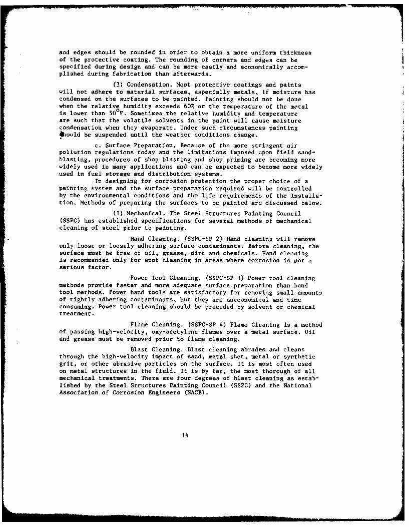
and edges should be rounded in order to obtain a more uniform thicknessof the protective coating. The rounding of corners and edges can bespecified during design and can be more easily and economically accom-plished during fabrication than afterwards.
(3) Condensation. Most protective coatings and paintswill not adhere to material surfaces, especially metals, if moisture hascondensed on the surfaces to be painted. Painting should not be donewhen the relative humidity exceeds 60% or the temperature of the metalis lower than 50 F. Sometimes the relative humidity and temperatureare such that the volatile solvents in the paint will cause moisturecondensation when they evaporate. Under such circumstances painting4hould be suspended until the weather conditions change.
c. Surface Preparation. Because of the more stringent airpollution regulations today and the limitations imposed upon field sand-blasting, procedures of shop blasting and shop priming are becoming morewidely used in many applications and can be expected to become more widelyused in fuel storage and distribution systems.
In designing for corrosion protection the proper choice of apainting system and the surface preparation required will be controlledby the environmental conditions and the life requirements of the installa-tion. Methods of preparing the surfaces to be painted are discussed below.
(1) Mechanical. The Steel Structures Painting Council(SSPC) has established specifications for several methods of mechanicalcleaning of steel prior to painting.
Hand Cleaning. (SSPC-SP 2) Hand cleaning will removeonly loose or loosely adhering surface contaminants. Before cleaning, thesurface must be free of oil, grease, dirt and chemicals. Hand cleaningis recommended only for spot cleaning in areas where corrosion is not aserious factor.
Power Tool Cleaning. (SSPC-SP 3) Power tool cleaningmethods provide faster and more adequate surface preparation than handtool methods. Power hand tools are satisfactory for removing small amountsof tightly adhering contaminants, but they are uneconomical and timeconsuming. Power tool cleaning should be preceded by solvent or chemicaltreatment.
Flame Cleaning. (SSPC-SP 4) Flame Cleaning is a methodof passing high-velocity, oxy-acetylene flames over a metal surface. Oiland grease must be removed prior to flame cleaning.
Blast Cleaning. Blast cleaning abrades and cleansthrough the high-velocity impact of sand, metal shot, metal or syntheticgrit, or other abrasive particles on the surface. It is most often usedon metal structures in the field. It is by far, the most thorough of allmechanical treatments. There are four degrees of blast cleaning as estab-lished by the Steel Structures Painting Council (SSPC) and the NationalAssociation of Corrosion Engineers (NACE).
14
. .. nL Mll n un.... -=-=- -... d
IWhite Metal Blast (SSPC-SP5 or NACE-1). Blast
cleaning to white metal is the ultimate in blast cleaning. It is usedfor coatings which must withstand exposure to very corrosive atmospheres(chemical, heavy industrial, or marine) where a high cost of surfacepreparation is considered to be warranted. This will contribute to maxi-mum performance of the paint system. This level of blast cleaning isrequired when zinc-rich coatings are used.
Near-White Metal Blast (SSPC-SP1O or NACE-2).In this procedure the blasted surface will show shadows, streaks and/ordiscolorations, but they will appear across the general surface areaand not be concentrated in spots. It has proven to be sufficiently ade-quate for many of the special coatings developed for long-term protectionin moderately severe environments.
Commercial Blast (SSPC-SP6 or NACE-3). Withthis blast all loose scale, rust and other surface contaminants areremoved. This method of surface preparation will result in a high degreeof cleaning and is generally considered adequate to the long life of themajority of paint systems under normal exposure conditions.
Brush-Off Blasting (SSPC-SP7 or NACE-4). Thisis a relatively low-cost method of cleaning to remove old finishes inpoor condition, loose rust and loose mill scale. Brush-off blasting isnot intended for use where severe corrosion is prevalent but is, instead,intended to supplant hand tool and power tool cleaning where blast clean-ing equipment is available. All blast cleaned surfaces require that primepainting be completed on the same day to prevent new corrosion productsfrom forming, since such blast cleaned surfaces are subject to rapidcorrosion if not coated.
Vacuum Blasting. Vacuum blasting is a relativelynew method, which minimizes the dust hazard and in which the blast abra-sive is reclaimed. This procedure, also known as dry honing, allowspractically no dust to escape and contaminate the atmosphere. It is veryefficient and economical for cleaning repetitive, small-scale surfacesin a shop.
Wet Blasting. This method reduces to a minimum thedust associated with blasting, but is not suitable for ail typas ofwork. Wet sand and other blast residues become trapped on upturned anglesand horizontal girders creating difficult clean-up work. These residuesmust be removed by rinsing, brushing or using compressed air; and thewet blasted surfaces will rust if not dried and primed immediately.
Centrifugal Blasting. This is a shop blasting methodin which the abrasive grit is dropped into a spinning vaned wheel ata controlled rate. The grit is thus impinged against the material movingbeneath it at a predetermined rate. This results in a controlled, uniformlycleaned surface. This type of surface preparation can be performed ata minimum cost, the abrasive can be reused and dust is virtually elimi-nated.
15

(2) Chemical Treatment. (SSPC-SP1). Chemical and solventcleaning methods are seldom if ever used in the field. They are usuallyrestricted to shop and tank immersion operations. They consist of solventwiping, alkali cleaning, steam cleaning, and acid cleaning.
Chemical methods of surface cleaning are usually moresuited to paint shop application, while mechanical methods are generallymore practical in field work. On the basis of overall effectivenessand efficiency, chemical cleaning is superior to mechanical methods, withthe exception of blast cleaning. The paint or paint system sejocted forany given surface and environment is of primary importance. The coatingand environment, then, determine the degree of surface cleaning required.The existing surface conditions, job location, equipment availabilityand economic factors will serve as a guide to the cleaning method required.
d. Methods of Application. The most common methods of applyingpaint are by brush, roller and spraying. Dip and flow coat methods arealso used but the mechanics of operation limit their use to shop work.Of the three for field use, brushing is the slowest, rolling is muchfaster and spraying is usually the fastest of all. The choice of methodis based on many additional factors such as environment, type of substrate,type of coating to be applied, appearance of finish desired and skillof personnel involved in the operation.
Environment. General surroundings may prohibitthe use of spray application because of fire hazards or potential damagefrom overspray. Adjacent areas not to be coated must be masked duringspraying. This results in loss of time and, if extensive, may offset theadvantage of the rapidity of spraying.
Type of Surface. Roller coating is the mostefficient on large flat surfaces. Corners, edges, and odd shapes, however,must be brushed. Spraying is also most suitable for large surfaces,except that it can also be used for round or irregular shapes. Brushingis ideal for small surfaces or for cutting in corners and edges.
Type of Coating. Rapid drying, lacquer-typeproducts, e.g., vinyls, should be sprayed. Application of such productsby brush or roller may be extremely difficult especially in warm weatheror outdoors on breezy days.
Appearance of Finish. Coatings applied by brushmay leave brush marks in the dried film; rolling leaves a stippled effectwhile spraying yields the smoothest finish, if done properly.
e. Basic Application Procedures. To obtain optimum per-formance from a coating, there are certain basic application procedureswhich must be followed, regardless of the type of equipment selected forapplying the paint. Cleaned, pretreated surfaces must be first-coatedwithin specific time limits established in order to minimize re-contamination.It is essential that surface and ambient temperatures are between 50°F
16
and 90°F for water-thinned coatings and 45°F to 950F for other coatings,unless the manufacturer specifies otherwise. The paint material shouldbe maintained at a temperature of 650 F to P50 F at all times. Paint shouldnot be applied when the temperature is expected to drop to freezingbefore the paint has dried. Wind velocity should be below 15 miles perhour and relative humidity below 80 percent. Masonry surfaces that aredamp (not wet) may be painted with latex or cementitious paints; otherwise,the surface must be completely dry before painting. When successive coatsof the same paint are used, each coat should be tinted differently toaid in determining proper application and to assure complete coverage.
Brush. Rapid drying, lacquer-type products (e.g., vinyls)are very difficult to apply with brushes. Most other types of paintscan be applied with brushes but if not done properly brush marks canbe left in the dried film. Brush application is the slowest method ofapplication but for trim, corners, door and window frames and areasdifficult of access no other method is satisfactory. Brush applicationis the only method of applying high viscosity coatings.
Roller. Roller application of paint is rapid and largesurfaces areas can be covered in a short period of time.
There are recent advances in rollers by which paint isfed to the inside of a roller by pressure so that it is not necessaryto keep reloading the roller periodically. By this method the speedof application is considerably increased.
Spray. Spray equipment is available in three generaltypes.
Conventional Spray. The coating material is placedin a closed container. Pressurized air from a compressor forces thematerial through a hose to the spray gun. The gun is also connectedto a separate air hose. At the gun, the material is atomized by the airsupplied through the central openings in the air cap. This is the mostinexpensive and most common spray technique but it tends to create exces-sive overspray because of the high ratio of air to paint used.
Airless Spray. In this method, coatings are sprayedby the use of hydraulic pressure alone. The equipment is similar toconventional spray except that the compressor operates a hydraulic pump.The material is atomized by forcing the material through a speciallyshaped orifice at a pressure of between 1,500 and 3,000 pounds per squareinch. Airless spraying usually permits the use of products with a higherviscosity. Considerable caution must be exercised because of the highpressures required.
Hot Spray. The hot spray technique can be adaptedto either conventional or airless spray painting. The paint temperatureis raised to 130 to 180°F to lower the viscosity and reduce the quantityof solvent needed. The resultant coating has higher solids and willproduce greater film thickness per coat. Considerable caution must beexercised because of the personnel and fire hazards due to the high tem-peratures required.
17

Paint Mitt. The paint mitt is a mitten made of lambskinwith the wool exposed and lined to prevent paint leaking through to theuser's hand. It is excellent for applying paint to small pipes, railingsand similar surfaces.
b. Wrappings and Other Types of Coatings. In many undergroundinstallations impregnated wrapping materials are used to increase thethickness of the coating in order to better resist mechanical damage fromrocks, etc., in the soil. Some of the wrapping materials are discussedbelow.
Mill-coated Pipe. In recent years the use of mill-coatedpipe has been steadily increasing. Wrapping materials are applied overhot applied enamels under the most favorable conditions and, hence,the coatings are freer of defects.
Plastic Tapes. Pressure-sensitive plastic tapes for wrap-ping underground pipe or other structures such as tanks are essentiallyplastic protective wraps with an adhesive on one side to cause it toadhere to the pipe when applied to it under pressure. Polyvinyl chloridetapes are supplied in thicknesses of 10 and 20 mils. Polyethylene tapesare supplied in 12- , 14- , and 20-mil thicknesses.
Laminated Tapes With Primers. The major tape of thistype available today consists of uncured butyl rubber laminated to poly-vinyl chloride. Although it has no adhesive qualities it is applied toan adhesive primer while still wet.
Coal-Tar Tapes. Coal-tar tapes may be either hot-appliedor cold-applied. They generally consist of a layer of specified thicknessof coal-tar pitch applied to a coal-tar-saturated fabric, plus a thinnercoal-tar coating on top, with a separator (paper or plastic film) on topof the outer layer.
Extruded Plastic Coatings. One of the most recent methodsof pipe protection underground is the extruded polyethylene coating.This coating is applied at the mill to small-diameter pipe.
Asbestos Wrappers. The asbestos felt wrapper is saturatedwith either asphalt or coal-tar enamel before application. This wrapperis applied directly over hot enamel as it is flooded or sprayed on thepipe.
Glass Outer Wrap. Glass outer wrap is a thick film ofglass fibers held together with a binder. This wrap may or may not befurnished saturated with tar or asphalt cutback before application.It is also applied directly over the hot enamel as it is flooded orsprayed on the pipe.
Glass Inner Wrap. Glass in the form of single filamentslaid down in random form and bonded together with a tough, flexiblebinder, is formed into a wrapper that is used with hot enamel applications.
18

g. Coating Maintenance. Paint systems deteriorate and willlose their protective ability unless the film remains intact.
Inspection. All coated structures above ground shouldbe inspected at definite intervals. They should be inspected at 6-monthintervals in exterior or corrosive environments and at yearly intervalsin other environments. Buried structures should be inspected wheneverexposed for any reason, especially if exposed for the repair of leaks.The condition of the structures with reference to type and stage ofdeterioration should be determined and recommendations made for the typeof maintenance to be performed after each inspection.
Recoating. Recoating can be considered, roughly, in twocategories. Data from the Inspection Records will determine the necessityfor spot painting or complete painting.
Spot or Touch-up. Spot painting should be performedwhen there are only local areas of failure such as at sharp edges, seams,pinholes and holidays, with the greater portion of the coating in satis-factory condition. Spot painting prolongs the time required before completerepainting because it stops the spread of deterioration and decreasesthe cost of surface preparation.
Total Recoating. If a protective coating is permittedto deteriorate excessively, then it becomes necessary to completelyrecoat the structure. Complete recoating necessitates the complete removalof the old coating, a completely new surface preparation, and the applica-tion of a completely new coating system. Such extensive maintenanceprocedures are expensive, and relatively more frequent maintenance pro-cedures should be adopted to maintain structural integrity of the system.
5. Corrosion Control by Cathodic Protection. Cathodic protectionis very simply, the use of direct-current electricity from an externalsource to oppose the discharge of corrosion current from anodic areas.When a cathodic protection system is installed, for maximum effect allportions of the protected structure collect current from the surroundingelectrolyte and the entire exposed surface becomes a single cathodicarea - hence the name. In all cases of underground corrosion, anodicareas and cathodic areas are present on a metallic structure (e.g.,steel). At the anodic areas, where corrosion occurs, current flows fromthe anode into the surrounding electrolyte (soil or water). Likewise,where current flows from the electrolyte onto the structure, the surfaceof the structure is cathodic and does not corrode.
Hence, if every bit of exposed metal on the surface of a structurecould be made to collect current, it would not corrode because the entiresurface then would be cathodic. This is exactly what cathodic protectiondoes. Direct current is forced to flow from a source external to thestructure onto all surfaces of the structure. When the amount of thiscurrent flowing is adjusted properly, it will counteract corrosion currentdischarging from all anodic areas on the structure; and there will be
19

a net current flow onto the structure surface at these points. The entiresurface then will be cathodic and the protection complete. It should benoted that only the exposed metal surface requires or utilizes a signif-icant amount of current. Therefore the current required to protect a coatedstructure is less than that to protect an uncoated structure of the samesize in the same environment. Complete and detailed application anddesign data on cathodic protection is contained in Section 7, Chapter4, Air Force Manual AFM 88-9, Corrosion Control.
a. General Requirements. The two methods of applying cathodicprotection are the sacrificial anode method and the impressed currentmethod. Both types of systems have certain essential features: (a) asource of electrons, called an anode, (b) z metallic electrlal path tocarry the electrons from the anode to the structure and (c) a continuouselectrolyte such as water or moist soil between the structure anC. theanode to complete the electrical circuit.
Sacrificial Anode Systems. In the sacrificial anode methodthe structure to be placed under cathodic protection is metallicallycoupled to a metal less noble (more negative) than itself. For example,zinc is less noble than steel and can be usee to cathodically protectsteel structures. A galvanic cell is thereby established in which theprotected structure becomes the cathode and the less noble metal, thesacrificial anode. Current flows through the electrolyte from the anodeto the cathode. The system is designed so that sufficient current willflow from the anode to suppress all local act'on currents on the surfaceof the protected structure.
Impressed Current Systems. In the impressed current methodof cathodic protection, the consumption of the anode material is not usedto supply the required current. Any available source of direct current maybe used provided it is continuous. A.C. rectifiers are generally used forthis purpose. However, motor-generator sets, gasoline engine generators,and wind-driven generators have been used. The direct current enters theelectrolyte from the anodes, flows to the protected structure, and isdrained back to the current source through a metallic circuit.
Where Applicable. Cathodic protection can be used toprotect any metallic structure from corrosion whose surfaces are contactedby an electrolyte (a current conducting liquid) which may be eithersoil or water.
Field Surveys. Before a cathodic protection system isdesigned, it is necessary to conduct a field survey of the intendedsite to determine and obtain information on the characteristics of theenvironment.
Other Cathodic Systems. Tt is necessary to knowwhether any cathodic protection systems exist In the area. If so, itmust be determined whether there will be any interference between thetwo: whether either system will interfere with the other's operation.
20

M -p
Soil Survey. Soil characteristics, the most impor-tant of which are resistivity, pH, and degree of aeration, must be deter-mined. The characteristics of the soil which will be in contact withthe structure are very important to the design of the system.
b. Determination of Protective Requirements. Cathodic protec-tion is used almost universally in conjunction with a protective coatingsystem of some kind. The use of such combinations reduces the current
required to achieve complete protection. Protective coating systemsnever form a completely perfect or impervious barrier against intrusionof the environment to the metal surface. Also, such coatings tend todeteriorate with time. Cathodic protection furnishes protection against
such defects; thus, such a combinato,- affords complete protection againstcorrosion.
c. Cathodic Protection System Design. The information obtained
from the field surveys and from th, protective requirements should providea basis for the design of the cathodic protection system. One of the mostimportant things to be realized in designing a cathodic protection systemis that it should be over designed: usually, from two to three timesthe initial current requirements are designed into the system. The reasonsfor this is that: (a) the protective coating will deteriorate with age,necessitating an increase in required current; and (b) usually, sometimeduring the life of the system, additio1.; will be made to the system,thus increasing the requirement for additional current.
Impressed Current vs. Sacrificial Galvanic Anodes. The useof galvanic anodes for cathodic protection is limited to areas where thesoil conductivity is high enough to permit sufficient current to flow toachieve the desired protection with a reasonable number of anodes. Thisis due to the relatively low driving potential between the sacrificialanodes and the structure, usually less than one volt. If electricalpower is available locally, it is usually less expensive to use an impressedcurrent cathodic protection system, especially if it will be in operationfive or more years. If power will not be available or the system willbe needed only temporarily, it is usually more economical to use sacrificialgalvanic anodes such as zinc, magnesium, or aluminum. Galvanic anodeshave the advantage of providing only a given known potential, withoutfluctuations that may occur with an impressed current system.
Selection of Anodes.
Impressed Current Anodes. Impressed current anodesare made of graphite, high silicon cast iron (Duriron), steel, platinum,platinized titanium, scrap steel, old rails and pipe, and lead. Availability,
cost, life expectancy and type of environment (soil or water) determinewhich type of anode to use. Where large amounts of current are required,impressed current systems are usually more econemical.
21

Sacrificial Galvanic Anodes. Sacrificial galvanicanodes are made from special aluminum, magnesium or zinc alloys. Theselection of a specific sacrificial anode should be based upon the requireddriving po,:'ntial, soil characteristics, availability, cost, weight anddurability. L i soils application they are generally used where relativelysmall increments of current are required and where the soil resistivityis low enough to permit obtaining the desired current with a reasonable
number of anodes.
Anode Placement. The placement of either impressed orsacrificial anodes depends upon the geometry of the system, the currentrequired, the desired system lifetime, the environmental characteristics(such as type of electrolyte), and resistivity. The configuration ofthe system also dictates the place nt of anodes because it is important
that no portion of the structure be shielded from the currents travelingto it through the electrolyte.
Testing. When a cathodic protection system is installed,test points and alarm signals should be installed so that the conditionand operation can be checked periodically. Testing of cathodic protectionsystems is very well described in Air Force Manuals AFM-88-9, Chapter4, Section VIII, Corrosion Control, and in AFM-85-5, Maintenance andOperation of Cathodic Protection Systems.
Automatic Control and Alarm Systems. Where soilresistivity fluctuates or where periodic inspection is impractical,the installation of automatic controls on an impressed cathodic protectionsystem, available from a number of cathodic protection companies, shouldbe considered.
In remote areas or even critical portions of localsystems it might be advantageous to have alarm systems to alert personnelwhen a system or portion of one is damaged or rendered inoperative.Again, such systems are available from many commercial companies.
Nonautomatic Test Systems. Tests which are madeperiodically to monitor the operation of a cathodic protection systemare described below.
Potential Measurements. Structure-to-soil potentialsshould be measured to determine the effectiveness of the cathodic protec-tion being furnished.
Current Measurements. The measurement of currentoutput is used to determine the operating condition of anodes and/orrectifiers and to insure that sufficient current is being applied to theprotected structure.
Resistance (Resistivity) Measurements. Theability of soil or water to conduct electricity is closely related tothe rate at which buried or immersed structures will corrode: the lowerthe resistance to current flow the higher the rate of corrosion. Thepractical measure of the ability of a material to resist the flow ofelectricity is known as resistivity. The greater the soil resistivitythe lower its corrosivity.
22

SECTION IV
Corrosion and Corrosion Control of Internal Surfaces
In order to properly design aviation fuel storage and distributionsystems from the standpoint of corrosion control it is first necessaryto define the corrosive environment. Then, corrosion-control methodscan be selected to insure that the lifetime of the fuel system will becommensurate with the projected lifetime of the overall facility.
1. Classification of Environment. Materials in fuel distributionsystems are exposed to many different environmental conditions. Properdefinition of these conditions is essential in the design of effectivecorrosion control methods for these systems.
a. Total Immersion. Many portions of aviation fuel supplysystems such as pipelines and valves are normally completely filled withfuel at all times. This constitutes total immersion. Short periods ofatmospheric exposure due to equipment failure or periodic maintenancewill not significantly change the behavior of most materials from theirbehavior during constant total immersion. The behavior and protection ofmaterials in conditions of total immersion is dependent primarily uponthe fuel, contaminants, temperature, and velocity.
Fuel Classes. Aviation fuels are designated as classesaccording to their source.
Liquid Hydrocarbons. Liquid hydrocarbons are thefuels derived from petroleum.
Aviation Gasolines. Low flashpoint but a flammablemixture is always present in the vicinity of leaks or where spillagehas occurred.
Blended Gasoline, kerosene and light distillates(JP-4 Jet-Engine Fuel). High fire hazard because of extremely low flashpoint(-20 0F), and low volatility. Can be ignited by discharge of static elec-tricity generated by the flow of the fuel in pipes.
Kerosene and kerosene-type jet-engine fuels.
These are low-volatility, high flashpoint fuels.
JP-5 Fuel. Flashpoint is 1401F.
JP-7 Fuel. Flashpoint is 150 0 F. JP-7 fuelis highly refined, clear, colorless, thermally stable to withstand hightemperatures in jet-engine fuel systems at flight speed. Special materialssuch as aluminum alloys, stainless steel and non-metallics are requiredfor handling JP-7 fuel.
Methyl Alcohols. Methyl alcohol-water mixtures areused for power augmentation during take-off for certain piston-typeengines and gas-turbine jet aircraft.
23
... ... mtoiI mm mr mm-.,--- j -

Contaminants. The successful performance of aircraftengines depends upon the availability of high-quality fuel. The introductionLf any form of contaminant will lower the quality of the fuel and seriouslyi.'pair its efficiency or make it entirely unsuitable for use. The use ofconLaminated fuels can be the cause of serious damage to the engine and,in many cases, results in complete engine failure. Aircraft engine fuelscan be contaminated by the intermixing of petroleum products, by the
introducLion of foreign matter such as water or solids, or by chemicalreaction of the fuel with some component of the fuel handling system.
Intermixing of Products. For example a very smallamount of jet-engine fuel or diesel oil will contaminate a high-antiknockgasoline to such an extent that the gasoline loses its ability to resistknocking and loss of power results. Also, mixing can effect deteriorationof the fuel handling systems, e.g. a system designed to handle JP-5 willbe severely deteriorated if methyl alcohol-water mixture is introduced.
Water. Liquid hydrocarbon fuels are all lighterin weight than water and will separate sharply from entrained water instationary containers (storage tanks), after sufficient time has elapsedfor the water to settle to the bottom. The solubility of water in liquidhydrocarbons is quite low and decreases with the temperature. Thus,lowering of the fuel's temperature tends to release small amounts ofdissolved water. This tendency of the fuel to release dissolved waterduring lowering temperatures, until the dissolved water is releasedin the form of ice crystals at extremely low temperatures, has complicatedthe handling of these fuels and caused clogging of line strainers, filtersand filter/separators when such temperatures are encountered. At temperaturesbelow that at which water will freeze, the passage of fuel to aircraftengines can be blocked by ice in the aircraft's fuel-system. For thisreason, it is of critical importance to prevent delivery of fuel containing
free water to any aircraft.
Foreign Solids. Solid contaminants such as foreigndebris, or normal rust particles from steel tanks and piping systems,must be prevented from entering the fuel systems of all types of aircraft,as they will cause clogging of the filters on the engine-fuel feed linesand scoring of close Drecision-fit moving engine parts is passed throughthe filter. Also, metal ions such as Fe+ t, Zn++ , Cu++ can degrade thethermal stability of JP-7 fuel.
Contaminants Picked Up From Contact With Componentsof the F'uel-Handling System. Two of the minor components that may bepresent in aircraft engine fuels are mercaptans and naphthenic acids.Mercaptans are sulfur compounds which are limited by current specifications
for jet-engine fuels to a maximum concentration of 0.005 percent. Mer-captan sulfur will cause corrosion of cadmium, and zinc if present in the
system, and the corrosion is greater if water is present. Napthenic acidsare organic acids which can be present in high-boiling jet-engine fuels.However, their concentration is not limited in present aviation fuel
specifications. Zinc is rapidly attacked by the naphthenic acids to
24
produce zinc naphthenates, which are soluble in the fuel. Minute amountsof zinc have been found to be highly detrimental to hot parts of aircraftengines; zinc penetrates along the grain boundaries causing embrittlementof the parts. For this reason, zinc-containing coatings, zinc coatedand galvanized materials will not be permitted in storage tanks or anyother parts of the fuel handling system that come in contact with thefuel. In addition, cadmium-plated steel, copper and copper alloys, becauseof their susceptibility to corrosion attack by the fuels, shall notbe used for components of the aircraft/engine fuel handling system.Steel, black iron stainless steels and some aluminum alloys are lesssusceptible to corrosion by the fuels, hence their use is permitted.Methyl alcohol is corrosive to aluminum alloys, therefore its use insuch a system is prohibited but the use of carbon steel and nonferrousalloys other than aluminum are permitted.
Harmful Effects on Materials. One characteristic ofall gasolines, and to some degree their vapors, is their ability todissolve petroleum oils and portions of grease. This must be taken intoconsideration in the specifications for lubricants for pump shafts andvalves for gasoline service. Some pipe-thread joint pastes that are immuneto solution in lower grades of gasoline are partially dissolved by thehigh-antiknock-value aviation gasoline containing aromatic hydrocarbons,and form a tacky mass, that will plug strainers and filters. High-antiknock-value aromatic aviation gasolines have the ability to soften and deterioratenatural rubber and some types of synthetic rubbers, and these cannot
be used in hoses, gaskets, packings, or other seals that come in contactwith the gasoline. Jet-aircraft engine fuels contain sufficient gasolineand aromatics to be capable of these same actions. In addition, the char-acteristics of a penetrating oil develop in jet-engine fuels and causepossibilities for leaks to occur where gasoline will not get through.
These characteristics also cause these fuels to loosen rust and scalethat have adhered to pipe and tank interiors of systems previously usedfor aviation gasoline. Methyl alcohol, and to some degree its vapors,will dissolve shellac, gums, dyes, and certain oils, but is not harmful
to rubber, asbestos, cork, and most valve packing. The alcohol will dis-solve or leach the asphalt in a pavement if allowed to drip or to spillwithout prompt removal by washing with a hose stream, or by absorbingit with sand, earth, or other inert material. Because of its lower rateof evaporation, jet-engine fuel is particularly harmful to such pavement.For this reason, rigid concrete pavement will be provided for the parking
of truck tanks at unloading positions or at truck-fill stands. Allpavement-joint sealers will be a jet-fuel-resistant type.
Microorganisms. With the advent of jet aircraft using
kerosene-type fuel, the presence of microorganisms in the fuel tanks,especially at the fuel/water interface became a serious problem. Largedeposits of sludge and bacterial growth in tanks caused widespread corro-sion, fouling of fuel filters and screens. General good housekeepingpractices are necessary to clean out accumulating sludge from time to
25

time. Elimination or removal of residual water, protective coatings andchemical additives are the usual methods employed for combating thebacterial growth problem.
Temperature. Because of the volatilization characteristicsof all aviation fuels, temperature is an important factor. As temperatureincreases the volatilization rate increases which can cause an increasein pressure in an unvented system. Therefore, the system must be eitheradequately vented or constructed of alloys capable of withstanding increasesin pressure resulting from increases in temperature.
b. Partial Immersion. Portions of aviation fuel systems suchas tank walls, particularly at the tops of the tanks and roofs usuallyare not in contact with the fuels. Condensation occurring on these portionscan cause corrosion; therefore, corrosion-control methods must be consideredfor these conditions.
c. Alternate Immersion. Portions of aviation-fuel systems suchas storage tanks, tank trucks, etc., usually are subject to alternateimmersion as the result of emptying and refilling. The conditions ofalternate immersion (alternate exposure to the fuel and the air) must beconsidered in the selection of corrosion-control methods for such appli-cations.
2. Corrosion Control by Materials Selection. The selection of materialswhich are compatible with the fuel to which they will be exposed is oneof the most effective methods of corrosion control. This selection shouldbe based upon the behavior of similar systems, previous performance,results of experimental tests, and the application of basic corrosionbehavior. The materials selected must also be compatible with other systemrequirements such as strength, weight, etc.
a. Basis for Materials Selection.
Behavior of Similar Systems (Previous Performance). Ifthere are aviation-fuel systems in use in which the materials have shownacceptable levels of corrosion resistance these same materials will nor-mally behave in a similar manner in a new system. The longer the timeof performance of the existing system the more reliable is the basis forthe materials selection.
Results of Experimental Tests. When the information requiredto select materials on the basis given in Section IV.1 is not available,other selection criteria must be used. Experimental tests, especiallylong-term tests, are often used as a basis for materials selection foraviation fuel systems. However, such test results must be applied judiciouslybecause seldom, if ever, do such tests duplicate all the variables encoun-tered in an actual installation.
Field Testing. In field testing, specimens of materialsare included in actual operating systems. With proper monitoring of oper-ating environments and application of accepted material exposure techniques,
26
m~mmmmmmm, .. a.m---. , -

Ithe results of these tests are useful in the design of systems usingthe same or similar fuels. These tests are, however, expensive and time-consuming. Such testing is justified only when the information used forthe selection criteria given above is not available. Field testing isuseful, however, in predicting actual system lifetimes and in establishingrealistic inspection and maintenance schedules for existing fuel systems.
Laboratory Testing. Corrosion testing under laboratoryconditions is useful in understanding the basic mechanisms of corrosionand determining the effect of environmental variables on metal behavior.They are normally, however, of rather short duration and usually do notsimulate actual operating conditions. Laboratory corrosion testing isnot, therefore, normally recommended as a basis for materials selectionfor fuel systems.
Galvanic Corrosion and Its Prevention. Galvanic corrosionof internal surfaces is attributable to the mechanism described earlierin this report. The basic methods of control of galvanic corrosion ofinternal surfaces are the same as outlined in that section: use samematerial throughout the system, use compatible materials throughout thesystem, or electrically isolate dissimilar materials. The compatibilityof dissimilar metals with one another is usually based upon a galvanicseries which is experimentally derived for a given environment.
Compatibility With Other System Requirements. As statedin Section 111.2 of this report the selection of materials for use inaviation-fuel systems must be based on many factors other than corrosion.Compatibility of the material with the fuel which it must contain ortransport is only one factor in materials selection. The selection criteriaare for materials which are commonly used in fuel systems and, therefore,meet many of the other selection criteria.
3. Corrosion Control by Protective Coatings. Protective coatingsare widely used to protect the interior surfaces of aviation-fuel systems.Their use is often limited by inaccessibility to interior surfaces; however,when protective coatings are properly selected and applied they can givelow-cost alternatives to the use of expensive construction materials.
a. Limitations of Coatings for Protection of Interior Surfaces.The major limitation in the use of protective coatings on interior surfacesis the inaccessibility to the surfaces. The interior surfaces of largefuel tanks are readily accessible. The relative accessibility of thesurfaces affects the initial application of the coating as well as theinspection and maintenance of the coated surfaces.
Initial Application. The methods used for surface prepara-tion and coating of internal surfaces prior to the application of protectivecoatings are the same as those stated elsewhere in this report. Tankslarger than 5000 gallons capacity are normally coated on site afterfabrication. Smaller tanks are normally shop-coated during manufacture.Many of the surface preparation and coating application methods described
27

in this report have been adapted to the shop coating of internal surfacesof small tanks. This equipment is normally automated. Sandblasting isthe normally used surface preparation method. Coatings are usually appliedby spraying.
Inspection and Maintenance. When the internal surfacesare accessible, such as in large storage tanks, the inspection and mainte-nance of the internal coating are readily accomplished when the tank isempty. Inspections should be made at each opportunity, especially whenthe tanks are being cleaned.
b. Selection of Coatings. Coatings for internal surfaces ofaviation-fuel systems, in addition to providing protection to the underlyingmaterial, must be compatible with the end use of the fuel. They must notcontaminate the fuel with material which adversely affects its quality.The selection of coatings for internal surfaces is based primarily uponaccepted industrial standards, although in many applications successfulfield experience is used.
Based on Specifications for Specific Applications. TheTechnical Manual on "'Interior Coating Systems for Surfaces in Contactwith Petroleum Fuels'' is an excellent guide to the selection of coatingsfor such applications. Coating systems for specific applications aregiven in Section V of this report under the appropriate system subheading.
Based on Field Experience. If standard coating systemsspecified for internal surface coatings have been unsatisfactory in fuelsupply systems or are unavailable in the -area and nonstandard coatingshave been used with satisfactory results then such nonstandard coatingsystems can be used. However, the use of such nonstandard coatings isrecommended only when it has been proven that the coating does notadversely affect the fuel quality, does not produce toxic effects andis approved by the cognizant AF office.
Surface Preparation. The applicability of any commonly usedsurface preparation methods to the preparation of internal surfaces forcoating may be limited by accessibility. However, most of the surfacepreparations are adaptable to the preparation of all but the most inacces-sible areas. The internal surface of large tanks can be cleaned usingmany of the mechanical methods outlined in Section 111.4 of this report.Since air pollution can be controlled in the cleaning of the internalportions of such tanks it is normally the preferred method of on-sitesurface preparation.
d. Methods of Application. When the surfaces are readily access-ible, such as in large tanks, any method of application described inSection 111.4 of this report can be used. Spraying is normally the mostcost-effective method of applying many coatings, although heavy coatingsare often applied using dauber techniques.
28
e. Coating Maintenance. Coating maintenance is normally notapplicable to inaccessible portions of fuel systems. When the surfacesare accessible then the maintenance of the coatings should be accomplishedaccording to the guidelines given in Section 111.4 of this report.
4. Corrosion Control by Cathodic Protection. The corrosion controlof internal surfaces of aviation fuel storage and distribution systemsis considered to be impractical at this time. However, under certainexceptional circumstances it might be considered although the presenceof such potential ignition sources in a fuel storage tank will limit theirapplication.
SECTION V
Specific Applications
1. Fuel Storage Facilities. Storage tanks for aviation fuels atinstallations within the continental limits of the United States shouldbe above ground to reduce the problems of external corrosion, inspectionand maintenance unless undergrouna tanks are specifically authorized.Storage of methyl alcohol and water-alcohol blends, and operating storageof aircraft-engine fuels at Air Force bases will normally be in under-ground horizontal tanks. Each fuel storage tank will be used for onlyone product and will be so marked. The bottoms of all tanks must have a5-degree slope to the drainage sump to facilitate the removal of anywater and sludge.
a. Materials Selection. Materials for construction of aviationfuel storage tanks must be compatible with the fuel to be stored or theymust be protected from corrosion. Steel is the normal material of construc-tion, but aluminum alloy, stainless steel or fiberglass-reinforced plasticstorage canks are used for special fuels. Since fuel storage tanks areusually large, material costs are an important part of the material-select:on process.
Steel Storage Tanks. Due to its high strength, toughness,and relatively low cost, steel is usually the material of choice forlarge fuel storage tanks. Steel tanks are used for storage of all aviationfuels except methyl alcohol, water-methyl alcohol blends and thermallystable (JP-7) aviation fuel. However, tanks used to hold JP-7 fuel mustbe internally coated to prevent fuel contamination.
Corrosion Resistance. Steel does not resist corrosionby either the atmosphere or the aviation fuels when moisture if present;and for these reasons, protective measures must be employed to preventcorrosion. Bare steel tanks shall not be used.
Methods of Protection. The most commonly acceptedmethods for protection of steel aviation fuel tanks are coatings andcathodic protection.
29
Exterior Protection, Above Ground. Protectionof undersides of flat-bottomed tanks is seldom critical. If the tankis placed on a well-drained sand pad it will be practically free fromcorrosion. However, if because of other special considerations additionalcorrosion protection is desired, the bottom may be painted, or oiled.The paint usually used is an asphalt varnish applied in one coat in accor-dance with Federal Specification TT-V-51A. Additionally, weld seams areusually protected L. 6-inch wide, 1/8-inch-thick asbestos strips whichhave been saturated with a high-melting-point, corrosion-inhibitive wax.Proper surface preparation and coating procedures as described in SectionIII of this report should be followed to insure desired coating performance.
For exposed surfaces of steel aviation fuelstorage their surfaces should be prepared and coatings applied accordingto the procedures given in this report. Alkyds are the most widely usedpaint systems but should only be used in non-marine rural or other mildlycorrosive environments. Alkyds may be applied over a commercially blastedsteel surface with good results. Two- or three-coat systems of six toeight mils total dry film thickness are recommended. The first coat shouldbe a primer and must be a minimum of two mils thick. If a high-build,two-coat system is being used, the primer may be three mils thick (dryfilm thickness). Topcoats are available in widely varying colors butare usually chosen to match the surrounding environmental coloration.Greens, browns, tans and white are used most frequently. For applicationof the exterior paint system the weather should be warm and dry. Theminimum temperature usually acceptable for painting is 50°F and the max-imum relative humidity is 60%. During painting there must be no tendencyfor condensation to occur on the steel surface from solvent evaporation.For exterior systems exposed in areas along the coast, or under marineatmospheric conditions which are generally aggressive, or for storagetanks which are exposed in highly corrosive industrial areas, additionalcorrosion protection is recommended. This may be obtained from a thickeralkyd system, for example an 8- to 10-mil alkyd system, or by going toother paint systems. Some of the other paint systems which have beenused are vinyl alkyds, vinyl acrylics, vinyls, PVA latex or an acryliclatex, silicone alkyds, and zinc-rich primer systems. A zinc-rich primedcoating system has a number of distinct advantages. Zinc produces a whitecorrosion product rather than the usual zed or reddish-brown steel corrosionproduct. For this reason rust stains are not produced on zinc-rich primedtanks. The zinc has excellent resistance against abrasion from rocks,etc., and generally protects the steel from abrasive damage of this type.Further, if a rupture occurs in the zinc-rich primer, it affords a degreeof cathodic protection in the area adjacent to the break. Both organicand inorganic zinc-rich primers are used with success for exterior primingof fuel tanks. If appearance is not a factor, the zinc-rich primer maybe used by itself as a coating system. It has excellent resistance againstatmospheric corrosion. However, it is subject to attack in industrialenvironments if they are either highly acidic or alkaline in nature.Under such corrosive industrial conditions it must be top-coated with
30

a suitably resistant topcoat system; vinyls or vinyl acrylics are frequently
used for this purpose. If appearance is a factor, some of the betterweathering topcoats include the acrylics, silicone alkyds, and vinylacrylics.
Exterior Protection, Below Ground. Steel storagetanks and other steel facilities underground are usually protected bya combination of a coating system and a cathodic protection system. Suchcombinations reduce the current required to achieve complete protection.Protective coating systems alone never form a completely perfect or imper-vious barrier against intrusion of the environment to the metal surface.Also, such coatings tend to deteriorate with time. Cathodic protectionfurnishes protection at such defects; thus, a combination affords completeprotection against corrosion. Coatings as described in AFM 85-3 shouldbe used in conjunction with a cathodic protection system installed inaccordance with AFM 88-9, chapter 4, section VII, August 1962.
Interior Protection. The entire interior surfacesof all steel fuel storage tanks must be coated; this includes the interiorsurfaces of roofs as well as both surfaces of floating roofs. Tanks willbe coated with an epoxy or urethane coating system as described in Depart-ment of Defense Manual AD 666969 'Interior Coating Systems for Surfacesin Contact with Petroleum Fuels.'' The tank surfaces shall be preparedfor coating in accordance with the requirements of paragraph 3-50g, AFM88-15, 11 Feb 1969.
Stainless Steel Storage Tanks. Stainless steel storagetanks shall be of welded construction of AISI Type 316L stainless steel.This type of tank shall be used for storing methyl alcohol, water-alcoholblends, or thermally stable (JP-7) supersonic aircraft fuels.
Corrosion Resistance. Type 316L stainless steel normallyis resistant to corrosion in most atmospheres. However, in heavy industrialor severe marine atmospheres light pitting can occur after a considerableperiod of exposure. Type 316L stainless steel is completely resistantto any chemical attack by the fuels listed above.
Methods of Protection.
Exterior Protection. Usually, no exterior pro-tection is required except for an occasional washing. It is a good practiceto wash such tanks occasionally to remove accumulated dirt, especially insevere marine and heavy industrial atmospheres, to prevent the possibilityof pitting or crevice corrosion.
Interior Protection. Type 316L stainless steelis used because it is immune to attack by the fuels stored in it; therefore,no interior protection is required. However, any water or sludge whichmight accumulate in the bottom should be removed during the regular inspec-tions.
31
Aluminum Alloy Storage Tanks. Aluminum-alloy storage tanksshall be of welded construction using alloys such as 5052, 5454, 5456,5083, 5086, 6061, 6063, 214 or 356. This type of tank shall be used onlyfor storing thermally stable (JP-7), supersonic aircraft fuels.
Corrosion Resistance. Aluminum alloys, such as thoselisted above are completely resistant to any chemical action of thermallystable aircraft fuels (JP-7).
Methods of Protection.
Exterior Protection. Except in severely corrosiveatmospheres (heavy industrial and severe marine atmospheres), aluminumalloys require no protective coatings unless coatings are desired fordecorative or camouflage purposes. Such coatings are specified in AFM85-3, Jan 1969. Protective coatings for heavy industrial and severe marineatmospheres are also specified in AFM 85-3, Jan 1969.
Interior Protection. To prevent contaminationof the JP-7 fuel a coating should be used to coat the interior surfacesof the aluminum alloy storage tanks.
Fiberglass-Reinforced Plastic Storage Tanks. Fiberglassreinforced plastic storage tanks should conform to specification MIL-P-22245. This type of tank is used for storage of methyl alcohol, alcohol-water blends, and thermally stable (JP-7) aircraft fuel.
Corrosion Resistance. These tanks must be completelyresistant to attack from any of the fuels intended for storage therein.
Methods of Protection.
Exterior Protection. This type of plastic issufficiently resistant to degradation in the atmosphere that no protectivecoatings are required.
Interior Protection. The type cf plastic forthis application is chosen because it is completely immune to degradationby the aviation fuels given in this report. Therefore, interior protectionis neither needed nor permitted.
2. Distribution Systems. Distribution systems are the means by whichthe aviation fuels are transported from the storage tanks to the pointof delivery to the aircraft. This system may he either above ground orburied or both. Corrosion control for such systems is important becauseof their high replacement cost, the potential for property damage, thepossible fire hazard from leakage, and the dependence of the consumeron an uninterrupted fuel supply. This corrosion control is accomplishedby proper material selection, system design, protective coatings andcathodic protection.
a. Material Selection. Material selection for distributionsystems should be based upon the criteria stated in this report. Distri-bution system components are exposed to the aviation fuel on the inside
32

and to either soil or atmosphere on the outside. The materials selectedmust be resistant to both environments or must be protected. The appli-cation of several commonly used distribution system materials is givenbelow.
Of the materials discussed below (steel, stainless steel,aluminum alloys, and fiberglass-reinforced plastic), only two can be usedunrestrictedly for all fuels downstream of the final filter-separator inthe distribution system: stainless steel and fiberglass-reinforced plastic.Steel may not be used at all, and aluminum alloys may not be used withmethyl alcohol or water-methyl alcohol blends.
Steel. Steel piping has excellent strength and ductility,is easily fabricated and has a low overall cost. Steel is satisfactorilyresistant to internal corrosion by aviation fuels and is used for allfuel distribution systems except methyl alcohol, water-alcohol blendsaad thermally stable (JP-7) fuel systems. The use of steel, as notedabove, is not permitted downstream of the final filter-separator in thedistribution system.
The external protection of steel piping above ground isachieved by coating. Coating systems should be selected and the basis ofcriteria given in Section I.4. Zinc rich coatings are normally recom-mended for this application and may be topcoated for cosmetic purposes.Other coating systems such as normal alkyd, bitumastic, and tar are alsocommonly applied to above ground piping.
The external protection of steel piping underground isachieved by coating, and, if required, by coating and cathodic protection.If the soil is aggressive or it a long system life is desired, cathodicprotection is recommended in addition to coating. The selection and designof such cathodic protection systems is discussed in Section 111.5.
Stainless Steel. AISI Type 316L stainless steel is usedfor distribution systems for methyl alcohol, water-methyl alcohol blends,and thermally stable (JP-7) aviation fuel because it is immune to corrosionby these fuels. It is one of the required materials for all aviation-fuelsystems downstream of the final filter-separator.
Stainless steel requires no internal protection and usuallyrequires no external protection in the atmosphere.
External protection underground may be required underparticularly aggressive conditions. In such cases the most satisfactoryprotective measures would be cathodic protection outlined above.
Aluminum Alloys. Aluminum alloys such as 5052, 5454, 5456,5083, 5086, 6061 or 6063 are used for the distribution systems for thermallystable (JP-7) aviation fuels. They may be used for all aviation fuelsystems except methyl alcohol and water-methyl alcohol blends downstreamof the final filter-separator.
Aluminum alloys require no internal protection and usuallyrequire no external protection in the atmosphere.
33

External protection underground may be required undercertain circumstances as described in Section III of this report. Ifprotection is required, it can be achieved by coating or cathodic pro-tection or both.
Fiberglass-Reinforced Plastic. Fiberglass-reinforced plasticconforming to specification MIL-P-2245 is suitable for distribution systemsfor methyl alcohol, water-methyl alcohol blends, and thermally stable(JP-7) aviations fuels. It is one of the materials to be used for allaviation-fuel systems downstream of the final filter-separator. Beforesuch reinforced plastic is specified, its compatibility with the particularfuel in question should be checked.
In general plastics require no protection, neither internalnor external.
b. Design. In order to insure the maximum reliability of aviationfuel distribution systems good design practices must be followed. Designcriteria and standards as specified in Chapter 14, AFM 88-15 and Chapter2, AFM 88-12 should be followed. To ensure maximum corrosion resist~aceother design factors are also important.
Couplings and Fittings. In order to minimize galvaaiccorrosion as described above in this report, galvanically compatiblematerials should be used for couplings and fittings used on metallicaviation-fuel distribution systems. If the piping materials are not suit-able for the fabrication of couplings or fittings then materials morenoble than the pipe should be used. This will prevent rapid corrosionof the couplings and fittings due to an unfavorable anode-to-cathode arearelationship. If more noble couplings and fittings cannot be used, elec-trical isolation from the pipe must be achieved. Insulating couplingsand bushings are available for such isolation. The materials of constructionmust be immune from attack by the aviation fuel. Also, smooth-faced couplingsare suggested. If the couplings do not present a smooth face toward theinternal flow, then severe turbulence can be generated and protectingcorrosion products can be removed by this turbulence. If the protectivecorrosion products are removed, extensive corrosion can result, usuallyjust downstream from the rough-faced couplings. This corrosion is a com-bination of cavitation corrosion and erosion corrosion.
Working Pressure. Normal working pressures of aviation-fuel distribution systems have little or no effect on corrosion. However,deterioration of the system must be taken into account in the determinationof safe working pressures. If significant deterioration is expected ordiscovered, working pressures should be reduced accordingly to avoidcatastrophic failures.
Stray Currents. Aviation-fuel distribution systems aresusceptible to corrosion by stray currents (electrical currents whichflow through paths other than the intended circuit). Direct currentssources are of primary importance. Alternating currents have little
34

effect on aviation-fuel distribution system materials. Stray currentsources are commonly grounded direct current powei supplies, electricwelding equipment, cathodic protection systems, and electroplating plants,etc. Any grounded direct current source can cause stray current corrosion.Stray-current corrosion occurs where the current leaves the structure andcan cause rapid failure. Stray-current corrosion can be minimized byconnecting the current source directly to the distribution system at thepoint where current would leave the structure. Stray-current corrosioncan also be minimized by the application of cathodic protection or theplacement of an intentional anode of scrap iron which is connected to thedistribution system at the point where current leaves the distributionsystem. In many cases the installation of insulating couplings in thesystem can make it a less favorable path for stray currents; however,if large potential gradients are present this practice may cause accel-erated attack at the insulating joint. Stray-current corrosion can usuallybe detected by measuring the pipe-to-soil potential over a long periodof time (24 hours). Since the direct current source usually fluctuatesin power level while other sources (galvanic or cathodic protectioncurrents) remain steady, fluctuations in pipe-to-soil potential willreveal the presence of stray currents. A potential direct current sourcewith a similar power fluctuation pattern can be located, and thus thestray-current source can often be determined.
Long-Line Currents. Long-line currents are similar tostray currents in effect but are caused by variations in soil type alonga pipeline. Long-line currents are, therefore, a type of concentrationcell-caused current. Passage of distribution systems through soils withdissimilar characteristics (salinity, resistivity, pH, etc.) should beavoided. If such routing is not possible, insulating couplings shouldbe installed in the system near the discontinuity between different soilconditions. Externally coated piping is less susceptible to long-linecurrent attack than is uncoatei piping. Also, since these currents areusually low, cathodic protection can usually eliminate attack from long-line currents and should be utilized whenever long-line currents are apotential problem.
c. Piping.
Steel. Bare carbon-steel pipe conforming to ASTM specifi-cations, except cross-country or other pipelines over a mile in length,shall conform to API standards for line pipe. Steel pipe shall be usedfor aviation fuel systems except downstream of the final filter/separatorand for special fuels (methyl alcohol, water-methyl alcohol blends andthermally stable (JP-7) aviation fuel).
Stainless Steel. Stainless steel (type 316L) piping shall1,e used downstream of the final filter/separator of all aviation-fuelsystems and for the complete distribution systems for methyl alcohol,water-methyl alcohol blends, and thermally stable (JP-7) aviation fuels.
35

Aluminum Alloys. Aluminum alloys piping shall be useddownstream of tie final filter/separator for all aviation-fuel systemsexcept the methyl alcohol and water-alcohol blend systems. It shall beused for the entire distribution system for thermally stable (JP-7)aviation fuel.
Fiberglass-Reinforced Plastic. Fiberglass-reinforced plasticpiping shall be used downstream of the final filter/separator of allaviation fuel systems and 'or the complete distribution systems for methylalcohol, water-alcohol blends and thermally stable (JP-7) aviation fuelsystems.
d. Fittings. Fittings for all piping should be fabricated fromthe same material as the pipe wherever possible; the use of dissimilarmaterials will result in galvanic corrosion. This attack can be minimizedby the resistivity of the electrolyte (water when present), small differ-ences in galvanic potential, favorable anode-to-cathode area relationships,large distances between anodes and cathodes, and high resistivity in themetallic current paths. Should the use of dissimilar metals be necessary,galvanic corrosion should be minimized by application of these measures.Complete electrical isolation between dissimilar components is oftenaccomplished by utilization of insulating couplings or flanges; theyshould be included in the design of the aviation-fuel distribution systemwhere galvanic corrosion is a potential problem. Fittings should bedesigned to present a smooth surface to the internal flow to reducefriction losses in the system and to reduce turbulence which can causecavitation corrosion, erosion corrosion or impingement attack.
e. Tank Trucks. Tanks for trucks used for transporting aviationfuels from any point downstream of the final filter/separator to planesshall be AISI type 316L stainless steel or an aluminum alloy such asspecified above in this section. However, aluminum alloy tanks shall notbe used for transporting methyl alcohol or vater-methyl alcohol blends.
36

SOR W "
SECTION VI
APPENDIX - GLOSSARY OF TERMS
Abrasive -- The agent used for abrasive blast cleaning; for example,sand, grit, steel shot, etc.
ABS plastic -- Acrilonitrile-butadiene-styrene plastic.
Absorption -- Process of soaking up, or assimilation of one substanceby another.
Active -- Referring to the negative direction of electrode potential,Antonym; noble.
Adhesion -- Bonding strength, the attraction of a coating to the surfaceto which it is applied.
Adhesive -- A substance capable of holding materials together by surfaceattachment.
Air drying -- Drying by oxidation or evaporation by simple exposure toair.
Airless spraying -- Spraying using hydraulic pressure to atomize thepaint.
Air volume -- Quantity of air in cubic feet (usually per minute) atatmospheric pressure.
Alcohol -- a flammable solvent; alcohols commonly used in painting areethyl alcohol (ethanol) and methyl alcohol (Methanol, woodalcohol).
Alkali -- Caustic, such as sodium hydroxide, lye, etc.
Alkyd plastics -- Plastics based on resins composed principally ofpolymeric esters, in which the recurring ester groups are anintegral part of the main polymer chain, and in which estergroups occur in most cross-links that may be present betweenchains.
Alligatoring -- Surface imperfections of paint having the appearance of
alligator hide.
Amide -- Curing agent -ombined with epoxy resins.
37

Amine -- Curing agent combined with epoxy resins.
Anaerobic -- Free of air or uncombined oxygen.
Anode -- An electrode of an electrolytic cell at which a net oxidationreaction occurs. In corrosion processes, the anode is theelectrode that has the greater tendency to go into solution.Antonym: Cathode. Synonym: See inert anodes, sacrificial anodes,and auxiliary electrodes.
Anodic protection -- A technique to reduce corrosion of a metal surfaceunder some conditions by passing sufficient anodic currentto it to cause its electrode potential to enter and remain inthe passive region.
Asphalt -- Residue from petroleum refining; also a natural complexhydrocarbon.
Auxiliary electrode -- An electrode commonly used in polarizationstudies to pass current to or from a test electrode. It isusually made out of a noncorroding material.
Barrier coating -- Shielding or blocking coating or film.
Bell end -- An enlarged portion of a pipe that resembles the socketportion of a fitting and that is intended to be used to makea joint by inserting a piece of pipe into it. Joining may beaccomplished by solvent cements, adhesives, or mechanicaltechniques.
Binder -- In a reinforced plastic, the continuous phase which holdstogether the reinforcement.
Bituminous coating -- Coal tar or asphalt based coating.
Blast cleaning -- Cleaning with propelled abrasives.
Blisters -- Bubbles in dry or partially dry paint film.
Bright blast -- White blast.
Brush-off blast -- Lowest blast cleaning standard, a light blast.
Caking -- Hard settling of pigment from paint.
Catalyst -- Accelerator; curing agent; promoter.
38
Cathode -- The electrode of an electrolytic cell at which net reductionoccurs. In corrosion processes, usually the area which is notattacked. Typical cathodic processes are cations taking upelectrons and being discharged, (e.g., 2H" H2 ) oxygen beingreduced, and the reduction from a higher to a lower valencestate.
Cathodic protection -- A technique to reduce corrosion of a metalsurface by passing sufficient cathodic current to it to causeits anodic dissolution rate to become negligible.
Caustic embrittlement -- That form of stress corrosion cracking occurringin steel exposed to alkaline solutions. (See stress corrosioncracking.)
Cavitation -- Damage of a material associated with collapse of cavitiesin the liquid at a solid-liquid interface.
Cell -- A system consisting of an anode and a cathode immersed in anelectrolyte. The anode and a cathode may be separate metalsor dissimilar areas on the same metal. When the electrodes arein electrical contact with each other, their difference inpotential causes current to flow and produces corrosion atthe anode.
Chalking -- The development of loose removable powder at or just beneathan organic-coating surface.
Checking -- The development of slight breaks in an organic coating whichdo not penetrate to the underlying surface. Checking may bedescribed as visible (as seen by the naked eye) or asmicroscopic (as seen under magnification of 10 diameters).
Chemical conversion coating -- A thin integral protective or decorativefilm produced in situ by chemical reaction of a metal with achosen environment.
Chlorinated rubber -- A particular film former used as a binder, madeby chlorinating natural rubber.
Coal tar-epoxy paint -- Paint in which binder or vehl le is a combinationof coal tar with epoxy resin.
Coatings -- Surface coverings; paints; barriers.
Coat of paint -- Layer of dry paint resulting from a single wetapplication.
39

Cohesion -- Property of holding self together as in a paint film.
Composition -- Analysis; make-up.
Cooling water -- Any water that removes heat from a point or area ofhigher temperature and delivers it to a point or area of lowertemperature.
Corrosion -- Oxidation; deterioration due to interaction with environment.
Corrosion fatigue limit -- The maximum stress endured by a metal withoutfailure in a stated number of stress applications under definedconditions of corrosion and stressing.
Corrosion potential (E ) -- The potential of a corroding surface inan electrolyterrelative to a reterence electrode. Synonym:rest potential, open circuit potential, freely corrodingpotential.
Couple -- See galvanic corrosion.
Cracking -- Splitting, disintegration of paint by breaks through a filmto substrate.
Crazing -- A network of checks or cracks appearing on a paint or plasticsurface.
Cross-spray -- Spraying first in one direction and then at right angles.
Cure -- To change the properties of a polymeric system into a final,more stable, usable condition by heat, radiation, or reactionwith chemical additives.
Curing agent -- A catalytic or reactive material which is required forcuring.
Decomposition potential (or voltage) -- The potential of a metal surfacenecessary to decompose the electrolyte of a cell or a substancethereof.
Degreaser -- Chemical solution (compound) for grease removal.
Depolarization -- The removal of factors resisting the flow of currentin a cell.
Deposit -- A foreign substance, which comes from the environment,adhering to a surface of a material.
40
1Descaling -- Removing scale.
Detergent -- Cleaning agent.
Dew point -- Temperature at which moisture condenses.
Dezincification -- A corrosion phenomenon resulting in the parting ofzinc from copper-zinc alloys (see parting).
Diffubio' -- The movement of material, such as a gas or liquid, inmaterial. If the gas or liquid is absorbed on one side of apiece of material and given off on the other side, the phe-nomenon is called permeability. Diffusion and permeabilityare not due to holes or pores but are caused and controlledby chemical mechanisms.
Dilutents -- See thinners.
Dispersion -- Suspension of one substance in another.
Dry spray -- Overspray or bounce back; sand finish due to spray particlesbeing partially dried before reaching the surface.
Drying time -- Time interval between application and a specifiedcondition of dryness.
Dry to touch -- Time interval between application and ability to betouched lightly (tack-free time).
Electrochemical cell -- See cell.
Electrochemical equivalent -- The weight of an element or group ofelements oxidized or reduced at 100% efficiency by the passageof a unit quantity of electricity.
Electrolysis -- The chemical change in an electrolyte resulting fromthe passage of electricity.
Electrolyte -- A chemical substance or mixture, usually liquid, containingions which migrate in an electric field.
Embrittlement -- Severe loss of ductility of metal or alloy.
Emulsion paint -- Water-thinned paint with an emulsified oil and/orresin or latex vehicle.
Enamel -- A paint which is characterized by an ability to forn anespecially smooth film, often an alkyd.
41

I
Environment -- The surroundings or conditions (physical, chemical,mechanical) in which a material exists.
Epoxy plas ±'q -- Ther-oplastic or thermosetting plastics containingether or hydroxy alkyl repeating units, or both, resultingfrom the ring-opening reactions of lower molecular weightpolyfunctional oxirane resins, or compounds, with catalystsor with various polyfunctional acidic or basic coreactants.
Erosion corrosion -- A corrosion reaction accelerated by abrasionby solid particles carried by a liquid or gas.
Extrusion -- A process whereby heated or unheated plastic forced througha shaping orifkce become one continuously formed piece.
Ferrous -- Iron containing.
Filiform corrosion -- Corrosion which occurs under films in the formof randomly distributed hairlines.
Filler -- A relatively inert material added to a plastic to modify itsstrength, permanence, working properties, or other qualities,or to lower costs. (See also reinforced plastic.)
Fluorocarbon plastics -- Plastics based on resins made by the polymeri-zation of monomers composed of fluorine and carbon only.
Film thickness -- Depth of applied coating, expressed in mils (1/1000 in.).
Fretting corrosion -- Deterioration at the interface between twocontacting surfaces accelerated by relative motion betweenthem.
Galvanic corrosion -- Corrosion associated with the current resultingfrom the coupling of dissimilar electrodes in an electrolyte.Also known as couple action.
Galvanic series -- A list of metals and alloys arranged according totheir relative corrosion potentials in a given environment.
Galvanized steel -- Steel coated with a thin layer of metallic zincapplied by a hot dip or electrolytic process.
Gel -- A jelly-like substance.
Gelling (gelation) -- Conversion of a liquid to a gel state.
General corrosion -- A form of deterioration that is distributed moreor less uniformly over a surface.
42

Gloss -- Shininess; lustre; ability to reilect in mirror direction.
Graphitic corrosion -- Deterioration of gray cast iron in which themetallic constituents are selectively leached or convertedto corrosion products leaving the graphite intact. (Seeparting.)
High build -- Producing thick dry films per coat.
Holiday -- Pinhole, skip, discontinuity, void in a paint film.
Holiday detector -- Device for detection of pinholes or holidays of anon-conductive film over a conductive substrate.
Humidity -- Measure of moisture content; relative humidity is the ratioof the quantity of water vapor in the air compared to thegreatest amount possible at the given temperature. Saturatedair is said to have a relative humidity of 100 percent.
Hydrogen embrittlement -- Embrittlement caused by entrance of hydrogeninto the metal. (As for example, through pickling or cathodicpolarization.)
Hydrogen overvoltage -- Overvoltage associated with the liberation ofhydrogen gas. (See overvoltage.)
Hydrostatic design stress -- The estimated maximum tensile stress inthe wall of the pipe in -he circumferential orientation dueto internal hydrostatic pressure that can be applied continu-ously with a high degree of certainty that failure of thepipe will not occur.
Immunity -- A state of resistance to corrosion or anodic dissolutioncaused by the fact that the electrode potential of thesurface in question is below the equilibrium potential foranodic dissolution.
Incompatibility -- Inability to mix with or adhere to another material.
Inert anode or electrode -- An electrode which does not corrode or reactunder an impressed anodic potential.
Inert pigment -- A non-reactive pigment.
Inhibitive pigment -- One which retards the corrosion process.
Inhibitor -- A chemical substance or combination of substances, whichwhen present in the proper concentration in the environment,prevents or reduces corrosion by a physical, physico-chemicalor chemical action.
43

Intercrystalline corrosion -- See intergranular corrosion.
Intergranular corrosion -- Preferential corrosion at grain boundariesof a metal or alloy. Also called intercrystalline corrosion.
Ion -- An electrically charged atom or group of atoms.
Iron rot -- Deterioration of wood in contact with iron.
Langlier index -- A calculated saturation index for calcium carbonatethat is useful in predicting scaling behavior of naturalwater.
Latex -- Rubber like; a common binder for emulsion (water) paints; thereare natural and synthetic latexes.
Leveling -- Flowing out to films of uniform thickness; tendency of brushmarks to disappear.
Lifting -- Softening and raising of an undercoat by application of a topcoat.
Long-line current -- Current flowing through the earth from an anodicto a cathodic area which returns along an underground metallicstructure (generally applied only where the areas are separatedby considerable distance and where current results fromconcentration cell action).
Mastic -- A heavy bodied high build coating.
(MEK) methyl ethyl ketone -- A strong flammable organic solvent.
(MIBK) methyl isobutyl ketone -- A strong flammable organic solvent.
Micron ' -- 1 x 10⁻⁶ meters.
Mil -- One one-thousandth of an inch.
Mill scale -- The heavy oxide layer formed during hot fabrication orheat treatment of metals and alloys.
Mixed potential -- A potential resulting from two or more electrochemicalreactions occurring simultaneously on one metal surface.
MVT (moisture vapor transmission) -- Moisture vapor transmission ratethrough a known membrane.
Noble -- Referring to positive direction of electrode potential, thusresembling noble metals such as gold and platinum. Antonym:active.
44

Noble potential -- A potential more cathodic (positive) than the standardhydrogen potential.
Non-ferrous -- Containing no iron.
Nylon plastics -- Plastics based on resins composed principally of along-chain synthetic polymeric amide which has recurringamide groups as an integral part of the main polymer chain.
Olefin plastics -- Plastics based on resins made by the polymerization
of olefins or copolymerization of olefins with other unsatu-rated compounds, the olefins being in greatest amount byweight. Polyethylene, polypropylene and polybutylene are themost common olefin plastics encountered in pipe.
Open circuit potential -- See corrosion potential.
Orange peel -- Dimpled appearance of dry film; resembling an orange peel.
Overcoat -- Second coat; top coat.
Overspray -- Sprayed paint which did not hit target; waste.
Overvoltage -- The change of an electrode potential from its reversibleequilibrium value due to polarization. (See hydrogen overvoltage
and polarization.)
Oxidation -- Loss of electrons by a constituent of a chemical reaction.
Oxygen concentration cell -- A galvanic cell resulting front differencein oxygen concentration between two locations.
Paint system -- The complete number and type of coats comprising a paintjob. In a broader sen.se, surface preparation, pre-treatments,dry film thickness, and manner of application are included inthe definition of a paint system.
Parting -- The selective attack of one or more components of a solidsolution alloy.
Pass (spray) -- Motion of the spray gun in one direction only.
Passivation -- A reduction of the anodic reaction rate of an electrodeinvolved in electrochemical acticn such as corrosion.
Passive-active cell -- A cell, the emf of which is due to the potentialdifference between a metal in an active state and the samemetal in a passive state.
45

Patina -- The green coating which forms on the surface of copper and
copper alloys exposed to the atmosphere.
Permeability -- See diffusion.
pH value -- Measure of acidity or alkalinity; pH 7 is neutral; the pHvalues of acids are less than 7, and of alkalis (bases) greaterthan 7.
Phenolic plastics -- Plastics based on resins made by the condensationof phenols, such as phenol and cresol, with aldehydes.
Pin-holing -- Formation of small hules through the coating.
Pits -- Corrosion of a metal surface, confined to a point or small areawhich takes the form of cavities.
Pitting Factor -- The ratio of the depth of the deepest pit resultingfrom corrosion divided by the average penetration as calculatedfrom weight loss.
Plasticizer -- A paint ingredient which imparts flexibility.
-- A material incorporated in a plastic to increase itsworkability and its flexibility or distensibility.
Polarization -- The deviation from the open circuit potential of anelectrode resulting from the passage of current, as for exampleachieving a protected potential of -0.9V with respect toCu/CuSO 4 electrode for a steel structure.
Polyester plastics -- Synonymous with alkyd plastics.
Polyethylene plastics -- Plastics based on polymers made with ethyleneas essentially the sole monomer.
Pol~merization -- A chemical reaction in which the molecules of a monomerare linked together to form large molecules whose molecularweight is a multiple of that of the original substance. Whentwo or more monomers are involved, the process is calledcopolymerization or heteropolymerization.
Polypropylene plastics -- Plastics based on polymers made with propyleneas essentially the sole monomer.
Poly(vinyl chloride) -- A resin prepared by the polymerization of vinylchloride alone.
Poroqity -- Degree of integrity or continuity of a paint film.
46

Pot-life -- Time interval after mixing of reactive components of a paintduring which liquid material can be properly applied.
Pre-treatment -- Treatment given a surface prior to applying a primer orfirst coat of paint. For example an acidified wash.
Profile -- Surface contour of a blast-cleaned surface as viewed fromthe eege; cross section of the surface.
Protective !ife -- Interval of time during which a paint system protectssubstrate from deterioration.
Reinforced plastic -- A plastic with some strength properties greatlysuperior to those of the base resin, resulting from the pre-sence of high strength filiers imbedded in the composition(see also filler).
Resin -- A material, natural or synthetic, contained in varnishes,lacquers and paints; the film former.
-- A solid, semisolid, or pseudosolid organic material which has
an indefinite and often high molecular weight, exhibits atendency to flow when subjected to stress, usually has asoftening or melting range, and usually fractures conchoidally.
Rest potential -- See corrosion potential.
Rigid plastic -- For purposes of general classification, a plastic thathas a modulus of elasticity either in flexure or in tensiongreater than 7000 kgf/cm 2 (100,000 psi) at 230C and 50% rela-tive humidity when tested in accordance with ASTM MethodsD747, Test for Stiffness of Plastics by Means of a CantileverBeam, ASTM Method D790, Test for Flexural Properties of Plastics,ASTM Method D638, Test for Tensile Properties of Plastics, orASTM Methods D882, Test for Tensile Properties of Thin PlasticSheeting.
Runs -- Curtains or sags in a paint film.
Rust -- Corroded iron; red iron-oxide deposited on metal; also othermetal oxides formed by corrosion of iron or steel.
Sacrificial anode -- An anode which corrodes and sacrifices itself,providing protection to an adjoining metallic component.
Sacrificial protection -- Reduction or prevention of corrosion of ametal in an electrolyte by galvanically coupling it to amore anodic metal.
47

Sandblast -- Blast cleaning using sand as an abrasive.
Saran plastics -- Plastics based on resins made by the polymerization of
vinylidene chloride or copolymerization of vinylidene chloridewith other unsaturated, compounds, the vinylidene chloride being
in greatest amount by weight.
Scale -- Rust or other deposits adhering or occurring in thin layers.
Scaling - Process of removing scale. (See descaling).
Season cracking -- A term usually applied to stress corrosion cracking
of brass.
Semirigid plastic -- For purposes of general classification, a plasticthat has a modulus of elasticity either in flexure or in ten-
sion of between 700 and 7000 kgf/cm2 (10,000 and 100,000 psi)
at 230 C and 50% relative humidity when tested in accordancewith ASTM Method D747, Test for Stiffness of Plastics by Means
of a Cantilever Beam, ASTM Method D790, Test for FlexuralProperties of Plastics, ASTM Method D638, Test for Tensile
Properties of Plastics, or ASTM Method D882, Test for Ten-sile Properties of Thin Plastic Sheeting.
Shelf-life -- Maximum interval in which a material may be stored and
still be in usable condition.
Shot blasting -- Blast cleaning using steel shot as the abrasive.
Silicone plastics -- Plastics based on resins in which the main polymer
chain consists of alternating silicone and oxygen atoms, with
carbon-containing side groups.
Solids -- Non-volatile portion of paint.
Solvent -- A liquid in which another substance may be dissolved.
Spalling -- The chipping, fragmentation, or separation of a surface or
surface coating.
Spark tester -- A high voltage holiday detector which sparks at holidays.
(See holiday detector.)
Standard electrode potential -- The reversible potential for an electrodeprocess when all products and reactions are at _1ii aCLIFityon a scale in which the potential for the standard hydrogen
half cell is zero.
48
Standard thermoplastic pipe materials designation code -- A means foreasily identifying a thermoplastic pipe material by means ofthree elements. The first element is the abbreviation for the
chemical type of the plastic in accordance with ASTM D1600.
The second is the type and grade (based on properties in accor-dance with the ASTM materials specification); in the case ofASTM specifications which have no types and grades or those in
the cell structure system, two digit numbers are assigned by
the PPI that are used in place of the larger numbers. Thethird is the recommended hydrostatic design stress (RHDS) forwater at 230 C (730 F) in pounds per square inch divided by 100
and with decimals dropped; e.g., PVC 1120 indicates that theplastic is poly-(vinyl chloride), Type I Grade 1 according toASTM D1784 with a RHDS of 2000 psi for water at 730 F. PE 3306
indicates that the plastic is polyethylene, Type III Grade 3
according to ASTM D1248 with a RHDS of 630 psi for water at730 F. PP 1208 is polypropylene, Class 1-19509 in accordance
with ASTM D2146 with a RHDS of 800 psi for water at 730 F; thedesignation of PP12 for polypropylene Class 1-19509 will becovered in the ASTM and Product Standards for polypropylene
pipe when they are issued.
Stray current corrosion -- Corrosion resulting from direct current flow
through paths other than the intended circuit. For example,by any extraneous current in the earth.
Stress accelerated corrosion -- The increased corrosion caused by applied
tensile stresses.
Stress corrosion cracking -- Premature cracking of metals produced by
the combined action of corrosion and surface tensile stress
(residual or applied).
Styrene-rubber plastics -- Compositions based on rubbers and styrene
plastics, the styrene plastics being in greatest amount by
weight.
Surface preparation -- All operations necessary to prepare a surface
to receive a coating of paint.
Tarnish -- Surface discoloration of a metal resulting from the formation
of a thin film of corrosion product.
Thermogalvanic corrosion -- rorrosion resulting from a galvanic cell
caused by a thermal gradient.
The -moplastic -- Capable of being repeitedly softened by heating and
hardened by cooling through a temperature range characteristicof the plastic, and that in the softened state can be s4hpedby flow into articles by molding or extrusion. i
49

Thermoset -- A plastic which, when cured by application of heat orchemical means, changes into a substantially infusible andinsoluble product.
Thinners o- Volatile organic liquids for reducing viscosity; solvents.
Tie coat - Intermediate coat used to bond different types of paintcoats.
Tooth -- Profile; mechanical anchorage; surface roughness.
Toxic -- Poisonous.
Toxicity -- Degree of poisonousness or harmfulness.
Throwing power -- The relationship between the current density at apoint on the specimen and its distance from the counterelectrode. The greater the ratio of the surface resistivityshown by the electrode reaction to the volume of resistivityof the electrolyte the better is the throwing power of theprocess.
Tuberculation -- The formation of localized corrosion products scatteredover the surface in the form of knoblike mounds.
Urethane plastics -- Plastics based on resins made by the condensationof organic isocyanates with compounds or resins that containhydroxol groups.
Vinyl plastics -- Plastics based on resins made from monomers containingthe vinyl group CH2 CH -.
Vinylidene chloride plastics -- See saran plastics.
Viscosity -- A measure of fluidity.
Viscosity cup -- A device for measuring viscosity.
Voids -- A term generally applied to paints to describe holidays, holes,and skips in the film.
Volatiles -- fluids which evaporate rapidly from a paint film.
Wash primer -- A thin inhibiting paint usually chromate pigmented witha polyvinyl butyral binder.
Weld decay -- Localized corrosion of weld metal.
White blast -- Blast cleaning to white metal.
50

SECTION VII
BIBLIOGRAPHY
Air Force Design Manual, Criteria and Standards for Air Force Construction,AFM 88-15, 11 Feb 1969.
Air Force Design Manual, Design Policy and Procedures, AFM88-29, 12 Feb
1970, Dept. of the Air Force.
Air Force, Permanently Installed Storage and Dispensing Systems forPetroleum and Unconventional Fuels, Air Force Regulation 91-13,13 Jan 1971.
Bell, Harold Sill, Petroleum Transportation Handbook, New York, N.Y.:McGraw-Hill Co., Inc., 1963, 484 pp.
Bigos, J., Greene, H. H., Hoover, G. R., ''Five Year Test Results-AISIResearch Project on Paintability of Galvanized Steel,'' Journal ofPaint Technology, Vol. 39 (no. 508), 1967, pp. 316-27.
Brown, P., ''Combating Metal Corrosion With Paints and Cathodic Protection,''Metal Finishing, Vol. 66, May 1968, p. 66.
Corrosion Control, AFM 88-9, Chapter 4., U.S. Dept. Air Force, Aug 1962.
Corrosion Control by Cathodic Protection, NAVDOCKS MO-307, 1964.
''Corrosion Control Methods,'' Pipeline Engineer, Mar 1964.
Corrosion Handbook, H. H. Uhlig, editor, New York, N.Y.: John Wiley andSons, Inc., 1948.
Department of Transportation Hazardous Materials Regulation Board, Title49, Transportation, Chapter 1, Part A5, ''Transportation of Liquids
by Pipeline.''
Design Manual-Liquid Fueling and Dispensing Facilities, NAVFAC DM-22,Washington, D. C.: Naval Facilities Engineering Command, 1968.
Freyling, E. N., Jr., and Menzler, George W., ''Adding Automatic Controlto Corrosion Protection,'' Chemical Engineer, New York, 1971, pp.78-79, 130, 132-133.
Harris, G. M., ''Plastic Tapes.'' Materials Protection and Performance,Vol. 9, No. 7, Jul 1970, pp. 26-28.
51

Hill, H. W., Jr., ''Properties of Polyethylene Sulfide Coatings,''American Chemical Society, Division of I and EC, Abstract of paperspresented at 163rd meeting, Boston, Mass, 1972.
Husock, B., ''Use of Pipe-to-Soil Potential in Analyzing UndergroundCorrosion Problems,'' Corrosion, Vol. 17, No. 8, Aug 1961, pp. 391t-395t.
Husock, B., ''Pipe-to-Soil Potential Measurements and Cathodic Protectionof Underground Structures,'' Materials Performance, Vol. 10, No. 5,May 1971.
Interior Coating Systems for Surfaces in Contact With Petroleum Fuels,Technical Manual AD-666 969, Washington, D.C: Office of Director
of Defense Research and Engineering, Mar 1968.
Jamar, L. G., ''The Forgotten Phenomenon,'' Air Force Civil Engineer,August 1972.
Maintenance and Operation of Cathodic Protection Systems, AFM 85-5, 1965.
McGregor, James M., ''Microorganisms Fail to Grow in Furane Lined JetFuel Storage Tanks,'' Materials Protection, Jun 1963, p. 24.
Military Standardization Handbook, Corrosion and Corrosion Protection ofMetals, MIL-HDBK-721(MRO, 1 Nov 1965).
Murphy, C. E., ''Quick Way to Determine Life Span of Sacrificial Anodes,''Pipe Line Industry, Vol. 20, Mar 1964, p. 44.
Myers, Dr. James R., Interior Corrosion of Fuel Storage Systems: Causesand Cures, Air Force Civil Engineer, Vol. 14, No. 3, 17-19 (1973)August.
Operation and Maintenance Guide Specifications, AFM 85-22, Chapter 9,Department of Air Force, Civil Engineering, General.
Paints and Protective Coatings, ARMY TM 5-618, NAVDOCKS MO-110, AirForce AFM 85-3.
Palmer, P. V., ''Galvanic Anodes,'' Corrosion Technology, Vol. 9, Sep 1962,p. 227.
Peabody, A. W., Control of Pipeline Corrosion, Houston, Texas: NationalAssociation of Corrosion Engineer, 1967.
''Plastics Pipe for Corrosive Petrochemicals,'' Corrosion Technology,Vol. 10, No. 4, 1963, pp. 85-88.
52

Reznek, Louis, Some Corrosion Problems of Tank Trucks and Their Solution,Corrosion, Vol. 14, No. 9, 1958, pp. 105-06, 110-12.
''Road Tankers - Some Design Factors,'' Petroleum, Vol. 19, No. 3, Mar1956, pp. 91-95.
Roberts, A. G., Organic Coatings-Properties, Selection and Use, NBS BSS7,Washington, D. C., 1968.
Romanoff, Melvin, Underground Corrosion, Bureau of Standards Circular 579,Apr 1957, 227 pp.
Schweitzer, P. A., 'Handbook of Corrosion Resistant Piping'', IndustrialPress, Inc., New York, N.Y., 1969.
Specifications for Preparing and Painting Steel, Steel Structures PaintingCouncil, Pittsburgh, PA.
Storage, Distribution and Dispensing of Aircraft and Automotive Fuels,Army TM5-848-2, AFM88-12, Chapt. 2, 1970.
Stringer, P. L., Long-Term Storage of Hydrocarbon Fuels in Coated Drums.Part III: Examination of Fuels After Five Years of Storage, ReportNo. DME-MP-30, National Research Council of Canada, Ottawa, Ontario,Division of Mechanical Engineers, 13 Mar 1964, CFSTI, AD-678-478.
Sudrabin, L. P., 'Cathodic Protection,'' Water and Waste Engineering,
Oct 1966, pp. 60-63.
''Tanks for Desert.'' Modern Plastics, Vol. 29, No. 10, Jun 1952, pp.76-78; and World Petroleum, Vol. 23, no. 9, Aug 1952, pp. 40-41.
''Title 49, Subpart I, Requirements for Corrosion Control,'' ASME Guide-lines for Gas Transmission and Distribution Piping Systems, 2nd ed.,New York, N.Y.: American Society of Mechanical Engineers, 1973, pp.85-89.
Uhlig, H. H., Corrosion and Corrosion Control, New York, N.Y.: John Wileyand Sons, Inc., 2nd ed., 1971, 419 pp.
Viable, J. B., 'Modified Cathodic Protection Method for ControllingCorrosion of Underground Steel Storage Tanks,'' Materials Protection,Vol. 6, No. 8 (1967), p. 31.
Via0le, J. B., ''Some O(servations on the Relationship of Cathode CurrentDensity to Area on Cathodically Protected Pipelines,'' HaterialsProtection, Vol. 6, No. 9, 1967, p. 47.
53

Wanderer, Edward T., Aluminum Alloys for Offshore Pipe Lines, National
Association of Corrosion Engineers, Corrosion, 1962.
West, L. H., ''Cathodic Protection of Buried Pipelines in Congested Areas,''
Materials Protection, Vol. 2, No. 11, Feb 1963, p. 14.
Whitney, J. F., and Wright, T. E., General Corrosion Considerations in
Laying Aluminum Pipe, National Association of Corrosion Engineers,18th Annual Conference, Kansas City, Mo., Mar 1962.
54