distance and communicdtion technologies for ledrning
TRANSCRIPT

Appendix A
History of Antiseep Collars
The purpose of this appendix is to explain:
• How antiseep (cutoff) collars were historically used in an attempt to prevent failures from uncontrolled seepage of water along the outside of conduits
• How research and improved understanding of failure mechanisms caused antiseep collars to be abandoned as a standard design element in embankment dams
• How filters provide improved protection against failures caused by water flowing along the outside of conduits installed in earthen embankment dams
Designers have always been concerned with seepage along conduits extending through earthfill or earth and rockfill embankment dams. Many observed failures of embankment dams have occurred near conduits, which accentuated this concern. Until about the mid-1980s, antiseep collars and careful compaction of backfill around conduits were the traditional methods for attempting to prevent problems caused by water flowing along the outside of conduits. As additional failures occurred, research was instituted to determine the basic mechanisms causing these problems. Once failure mechanisms were understood more completely, filters replaced antiseep collars as the preferred design tool to control seepage along conduits.
A.1 Concrete gravity dam experience
Concrete gravity dams were a popular type of water control structure early in the 1900s. Several failures of these structures caused a reexamination of design procedures. One approach to preventing failures of these dams from uncontrolled seepage under them was to increase the length of the flow path under the structures by using cutoff walls at the upstream and downstream edges of the dam. Studies of concrete gravity dam failures showed that some foundation soil types were much more likely to fail from water flowing under the dams than others were. Tables were developed that showed typical values of hydraulic gradients that were considered safe for different soil types. If a preliminary design showed that a hydraulic gradient was excessive, the structure was lengthened, or the dimensions of the cutoff walls were increased to reduce the gradient at the toe of the dam.
A-1

Conduits through Embankment Dams
An example of a table formerly used in designing concrete gravity dams is reproduced in table A-1 from Reclamation’s Design of Small Dams, First Edition (1960). The table shows twelve soil types and the “critical creep ratio” for each soil type. The term creep ratio basically represents the inverse of the hydraulic gradient in a structure design. Early designs without downstream drainage considered a structure to be safe against seepage forces if the computed creep ratio was larger than the values listed for the foundation soil type in the table. If the preliminary design was inadequate by this criterion, the length of the structure was increased, or the dimensions of the cutoff walls were lengthened. Later, more reliance was placed on drainage and filters downstream of the structures.
Table A-1.—Critical creep ratios for various soil types
Soil type Critical creep ratio*
Very fine sand or silt 8.5
Fine sand 7.0
Medium sand 6.0
Coarse sand 5.0
Fine gravel 4.0
Medium gravel 3.5
Coarse gravel including cobbles 3.0
Boulders with some cobbles and gravel 2.5
Soft clay 3.0
Medium clay 2.0
Hard clay 1.8
Very hard clay or hardpan 1.6
* A structure is considered safe only if the computed creep ratio is larger than the listed value for the foundation soil type. Higher creep ratios result from longer seepage distances and lower head differences. To increase the creep ratio of a design, cutoff walls were lengthened.
A-2

Appendix A—History of Antiseep Collars
A.2 Creep ratio tables
In the table in the previous section, the term creep ratio is defined as the weighted seepage path length divided by the difference in head between the upstream pool and the downstream discharge elevation.
Several important points are illustrated with this listing:
• Soils with the highest susceptibility to backward erosion piping are very fine sands or silts and fine sands, and soils with the lowest susceptibility are boulders with some cobbles and gravel, and clays.
• Clay soils have a high resistance to backward erosion piping, even whensubjected to large hydraulic gradients.
• Although a soil may not be susceptible to backward erosion piping, internal erosion of cracks may pose serious problems for these soils. The table does not address the resistance to internal erosion of various soil types, only the resistance to piping. The resistance to internal erosion primarily depends on the plasticity of the soil fines, the dispersivity of clay in the soil, and whether the soil is very broadly graded.
A.3 Antiseep collar design in earthen and earth-rock dams
Designers of earthen and earth-rock dams adopted the philosophy of increasing the length of the seepage path used for concrete gravity dams. Concrete collars termed antiseep collars were constructed at regular intervals along conduits through the dams to increase the length of the flow path of water along the outside of the conduit. The theory was that forcing water to take a longer seepage path would dissipate hydraulic forces and reduce the likelihood of piping at the downstream embankment toe. The collars usually extended outward from the conduit by a dimension equal to the diameter of the conduit, or more.
Antiseep collars were often constructed using the same materials used for the conduits. Probably the most common material was formed concrete. Steel, corrugated metal, and plastic collars have been used for conduits made of similar materials. Collars were spaced at regular intervals along the conduit within the predicted zone of saturation of the earthfill zone. In the case of central core fills with rockfill shell zones, the collars were usually installed only within the compacted core of the embankment.
The Soil Conservation Service, now the Natural Resources Conservation Service, constructed thousands of small, earthen embankment dams, many of them between
A-3

Conduits through Embankment Dams
1950-1970. Most of these sites had concrete conduits that would slowly release the temporarily impounded floodwaters. The design criterion used for most of those embankment dams arbitrarily required that the seepage path through the saturated portion of the embankment be increased by 15 percent by adding antiseep collars. This requirement did not vary with the soil type in the embankment dam. Usually, collars were spaced along the conduit every 20 to 25 feet through the earth core of zoned embankment dams or through the central portion of homogeneous dams.
Figure A-1 shows a conduit with antiseep collars with hand compacting of earthfill next to the conduit. Figure A-2 shows a failure of a conduit with antiseep collars constructed around the conduit.
A.4 Changes in philosophy
From 1960 to 1980, a number of small embankment dam failures occurred, even though antiseep collars were carefully installed in well constructed earthen embankments. Several of the failures were at structures designed by the Natural Resources Conservation Service. Sherard (1972) reported on a study of those failures. The study showed that intergranular seepage and associated backward erosion piping was not the mode of failure for these embankment dams. The failures usually occurred almost exclusively when the completed embankments were first subjected to a pool, long before a phreatic surface had time to develop through the compacted earthfill. Other studies by Sherard (1973) on larger earthen embankment dams attributed failures and near-failures to internal erosion of clay cores through hydraulic fractures in the embankment zones.
The reasons why antiseep collars were ineffective in preventing failures near conduits may be summarized as follows:
• The antiseep collars only influenced water flowing in the immediate vicinity of the conduit. The collars did not significantly affect the remainder of the surrounding earthfill. Most of the failures were found to have occurred not immediately along the conduit, but in compacted fill outside the zone of the antiseep collars.
• The antiseep collars were designed to increase head loss in intergranular seepage, but most failures occurred long before steady seepage conditions occurred. Studies showed the failures occurred from water flowing along cracks within the earthfill, and not through the soil immediately next to the conduit.
Sherard, Decker, and Ryker (1972) discuss the mechanisms by which failures can occur in the following quote from the reference. In the quote, the term piping is
A-4

Appendix A—History of Antiseep Collars
Figure A-1.—Hand tamping embankment material next to an antiseep collar.
Figure A-2.—Internal erosion failure along a conduit with antiseep collars.
A-5

Conduits through Embankment Dams
generically used to describe two distinctly different mechanisms of failure, backward erosion piping and internal erosion, as defined in this document. The glossary defines the terminology used in this document to describe these mechanisms in more detail. As quoted from the reference:
One main source of the commonly held idea that piping is most likely to damage dam structures in cohesionless soil is the experience which led to the establishment of the Bligh “creep ratio”, and, later the Lane “weighted creep ratio” theory. This theory was developed from studies of failures of concrete dams on soil foundations. Under the theory, cohesionless silts and very fine sands are the materials which require the longest seepage path to avoid piping: a weighted creep ratio of 8.5 or more is needed for dams underlain by very fine sand or silt, whereas a weighted creep ratio of 2.0 is adequate for foundations of medium clay.
It would appear, therefore, that the experience underlying the creep ratio theory indicates that piping of a given leak along a given seepage path is many times more likely to occur in fine sand than in clay. It is also apparent, however, that the conditions which are needed to cause piping of a leak passing through a soil foundation directly under a concrete dam are wholly different than those which are most likely to cause piping inside an earth embankment, because the concrete dam provides a roof for the leakage channel which cannot collapse. Hence, the conclusion that piping failures in homogeneous earth (embankment) dams may be statistically more likely in embankments of clay than in embankments of cohesionless soils does not conflict with the weighted creep ratio theory. Completely different mechanisms are involved in the two cases.
Because seepage was determined not to be the cause of most of the observed failures and because many of the failures occurred near conduits with properly designed and installed antiseep collars, designers reconsidered how best to prevent similar failures. Research by Sherard and others resulted in numerous seminal papers on the effectiveness of properly designed filters to collect flow through cracks in embankment dams. Other papers on causative mechanisms of cracks in embankment dams also were authored. Hydraulic fracture associated with differential movements in compacted fills was the primary mechanism identified as creating cracks through which scour could occur.
Based on this history, the major design organizations constructing embankment dams abandoned the use of antiseep collars in the mid-1980s. Seepage collars were seen to be ineffective in preventing many failures associated with conduits, and even thought possibly to have contributed to failures. By inducing additional differential settlement and impeding proper compaction around the conduits, cracking of the surrounding earthfill could more easily occur. The major design agencies adopted an alternative design measure to intercept water potentially passing through the earthfill surrounding conduits. The design includes a zone of designed granular filter surrounding the penetrating conduit. This filter zone is termed a filter diaphragm or collar.
A-6
Appendix A—History of Antiseep Collars
Since this type of design has come into common usage, very few failures have occurred. The filter is thought to intercept water that can flow through cracks in embankment dams. The filter has a designed gradation that blocks eroding soil particles and prevents subsequent enlargement of the flow path by sealing the avenue for erosion. Philosophically, the filter diaphragm is more of a crack interceptor and sealer than it is a collector of seepage. If seepage in the embankment dam is a concern, more substantial zones including chimney drains are required. The design and construction of filters is discussed in more detail in the body of the document.
References
Bureau of Reclamation, Design of Small Dams, First Edition, U.S. Government Printing Office, Washington, D.C. (contains summary of weighted creep ratio theory, p. 242.), 1960.
Sherard, James L., Study of Piping Failures and Erosion Damage from Rain in Clay Dams in Oklahoma and Mississippi, Report prepared for the Soil Conservation Service, USDA, 1972.
Sherard, James L., “Embankment Dam Cracking,” Embankment Dam Engineering, “Casagrande Volume,” John Wiley and Sons, New York, 1973, pp. 271-353, republished by American Society of Civil Engineers in Geotechnical Special Publication No. 32, 1992, pp. 132-215.
Sherard, James L., Rey S. Decker, and Norman L. Ryker, Hydraulic Fracturing in Low Dams of Dispersive Clays, Proceedings of ASCE Specialty Conference, Performance of Earth and Earth-Supported Structures, Volume 1, Part 1, Purdue University, June, 1972, pp. 653-689.
A-7

Conduits through Embankment Dams
A-8

Dam Location Topic Page
Anita Dam Montana Failure of an embankment dam by internal erosion along the outside of the outlet works conduit
1
Annapolis Maryland Forensic investigation of a spillway 5 Mall Dam conduit failure
Arkabutla Mississippi Construction error leads to defective 12 Dam joints in an outlet works conduit
Balman Colorado Reservoir evacuation by pumping and 18 Reservoir controlled breaching techniques Dam
Beltzville Pennsylvania Conduit crack survey 22 Dam
Bohemia Maryland Undermining and failure of a new 26 Mill Dam spillway conduit constructed on piles
Clair Peak Maryland Grouting from the embankment dam 30 Dam surface to fill voids along the outside of a
spillway conduit
Como Dam Montana Sliplining of an existing outlet works conduit using a steel pipe slipliner
34
Crossgate North Problems encountered during the 37 Dam Carolina construction of a new siphon spillway
Dalewood Mississippi Man-entry inspection of a deteriorated 39 Shores Dam corrugated metal outlet works conduit
Empire Colorado Reservoir evacuation using controlled 41 Dam breaching techniques
Hernandez California Conduit constructed over a cutoff trench 45 Dam
Appendix B
Case Histories
Index

Dam Location Topic Page
Lake North Dakota Grouting voids existing outside an outlet 50 Darling works conduit Dam
Lawn Lake Colorado Failure of an embankment dam by a 54 Dam combination of internal erosion and
backward erosion piping caused by pressurized leakage from the outlet works conduit
Little Ohio Separation of spillway conduit joints due 57 Chippewa to foundation movement Creek Dam
Loveton Maryland Failure of an embankment dam by 60 Farms Dam internal erosion along the spillway
conduit
McDonald Montana Steel lining of an existing outlet works 64 Dam conduit
Medford Maryland Failure of an embankment dam due to 67 Quarry internal erosion along the conduit Wash Water Lake Dam
Olufson Washington Outlet works conduit failure 69 Dam
Pablo Dam Montana Removal and replacement of an outlet works
72
Pasture Arizona Closed circuit television inspection of an 77 Canyon outlet works conduit Dam
Piketberg South Africa Failure of and embankment dam by 81 Dam internal erosion resulting from hydraulic
fracture of earthfill adjacent to the outlet conduit
Ridgway Colorado Grouting of cracks in an existing outlet 84 Dam works conduit
Conduits through Embankment Dams
B-ii

Dam Location Topic Page
Rolling Maryland Sliplining of an existing spillway conduit 87 Green using Snap-Tite HDPE Community Lake Dam
Round Rock Arizona Sliplining of an existing outlet works 89 Dam conduit using HDPE
St. Louis Missouri Conduit abandonment by grout injection 91 Recreation Lake Dam
Salmon Washington Man-entry and underwater inspections of 94 Lake Dam an outlet works conduit
Sardis Dam Mississippi A sinkhole developed over an outlet works conduit due to material being eroded through a joint
98
Sugar Mill Georgia Siphon spillway failure 101 Dam
Turtle Montana Sliplining of an existing outlet works 103 (Twin) Lake conduit using HDPE Dam
Upper Red Oklahoma Failure of an embankment dam by 105 Rock Site 20 internal erosion resulting from hydraulic Dam fracture of earthfill adjacent to the flood
control conduit
Waterbury Vermont Design and construction of a filter 108 Dam diaphragm around an existing outlet
works conduit
Willow Montana Lining of an existing outlet works conduit 112 Creek Dam using CIPP
Wister Dam Oklahoma Near failure of an embankment dam due 117 to internal erosion
Appendix B—Case Histories
B-iii

Conduits through Embankment Dams
Case Histories Grouped by Similar Topic
B-iv
Dam Location Topic Page
Failures and near failures of embankment dams
Anita Dam Montana Failure of an embankment dam by internal erosion along the outside of the outlet works conduit
1
Lawn Lake Colorado Failure of an embankment dam by a 54 Dam combination of internal erosion and
backward erosion piping caused by pressurized leakage from the outlet works conduit
Loveton Maryland Failure of an embankment dam by 60 Farms Dam internal erosion along the spillway
conduit
Medford Maryland Failure of an embankment dam due to 67 Quarry internal erosion along the conduit Wash Water Lake Dam
Piketberg South Africa Failure of an embankment dam by 81 Dam internal erosion resulting from hydraulic
fracture of earthfill adjacent to the outlet conduit
Upper Red Oklahoma Failure of an embankment dam by 105 Rock Site 20 internal erosion resulting from hydraulic Dam fracture of earthfill adjacent to the flood
control conduit
Wister Dam Oklahoma Near failure of an embankment dam due 117 to internal erosion
Design- and construction-related problems
Arkabutla Mississippi Construction error leads to defective 12 Dam joints in an outlet works conduit
Bohemia Maryland Undermining and failure of a new 26 Mill Dam spillway conduit constructed on piles

Appendix B—Case Histories
Dam Location Topic Page
Hernandez Dam
California Conduit constructed over a cutoff trench 45
Little Chippewa Creek Dam
Ohio Separation of spillway conduit joints due to foundation movement
57
Olufson Dam
Washington Outlet works conduit failure 69
Sardis Dam Mississippi A sinkhole developed over an outlet works conduit due to material being eroded through a joint
98
Inspection and evaluation
Annapolis Mall Dam
Maryland Forensic investigation of a spillway conduit failure
5
Beltzville Dam
Pennsylvania Conduit crack survey 22
Dalewood Shores Dam
Mississippi Man-entry inspection of a deteriorated corrugated metal outlet works conduit
39
Pasture Canyon Dam
Arizona Closed circuit television inspection of an outlet works conduit
77
Salmon Lake Dam
Washington Man-entry and underwater inspections of an outlet works conduit
94
Alternative reservoir evacuation
Balman Reservoir Dam
Colorado Reservoir evacuation by pumping and controlled breaching techniques
18
Crossgate Dam
North Carolina
Problems encountered during the construction of a new siphon spillway
37
Empire Dam
Colorado Reservoir evacuation using controlled breaching techniques
41
Sugar Mill Dam
Georgia Siphon spillway failure 101
B-v

Conduits through Embankment Dams
Dam Location Topic Page
Filter diaphragm construction
Waterbury Vermont Design and construction of a filter 108 Dam diaphragm around an existing outlet
works conduit
Conduit renovation
Como Dam Montana Sliplining of an existing outlet works 34 conduit using a steel pipe slipliner
McDonald Montana Steel lining of an existing outlet works 64 Dam conduit
Rolling Maryland Sliplining of an existing spillway conduit 87 Green using Snap-Tite HDPE Community Lake Dam
Round Rock Arizona Sliplining of an existing outlet works 89 Dam conduit using HDPE
Turtle Montana Sliplining of an existing outlet works 103 (Twin) Lake conduit using HDPE Dam
Willow Montana Lining of an existing outlet works conduit 112 Creek Dam using CIPP
Removal and replacement of conduit
Pablo Dam Montana Removal and replacement of an outlet 72 works
Conduit repair and abandonment
Clair Peak Maryland Grouting from the embankment dam 30 Dam surface to fill voids along the outside of a
spillway conduit
Lake North Dakota Grouting voids existing outside an outlet 50 Darling works conduit Dam
Ridgway Colorado Grouting of cracks in an existing outlet 84 Dam works conduit
B-vi

Appendix B—Case Histories
Dam Location Topic Page
St. Louis Recreation Lake Dam
Missouri Conduit abandonment by grout injection 91
B-vii

Conduits through Embankment Dams
B-viii

Appendix B—Case Histories
Project name: Anita Dam
Location: Montana
Summary: Failure of an embankment dam by internal erosion along the outside of the outlet works conduit
This case history illustrates an embankment failure likely caused by internal erosion despite the inclusion of antiseep collars. Dispersive clays also contributed to the failure.
Anita Dam is located about 22 miles north of Chinook, Montana, about 5 miles south of the Canadian border. The drainage, which normally flows only in response to snowmelt or heavy rain, is an unnamed tributary of the East Fork of Battle Creek, which flows southward into the Milk River.
Construction of Anita Dam was completed in November 1996. The embankment dam has a height of 36 feet, a crest length of about 1,012 feet, and a crest width of 14 feet. The reservoir impounds 794 acre-feet. The embankment was constructed with an overflow 36-inch diameter steel outlet conduit as the principal spillway. Two additional natural spillways were located on the reservoir rim to safely pass the probable maximum flood. The embankment was constructed as a homogeneous fill with a layer of upstream riprap. After the incident, it was determined that the fill material was a lean clay (CL) with dispersive properties.
The spillway conduit for Anita Dam utilized a series of concrete antiseep collars surrounding the conduit, but without a continuous cradle. During construction “flowable” backfill (essentially a high slump soil cement) was placed under the conduit to provide support between the antiseep collars. Rock-filled gabions were used at the downstream end of the conduit.
During the spring runoff of 1997, unusually heavy snowpack caused the reservoir to fill in the 4 days immediately prior to the failure. On the morning of March 26, a large leak beside the outlet conduit was noticed (figure B-1). Emergency response teams were dispatched to the site.
Upon arrival, the teams verified the large amount of leakage around the conduit, along with multiple vortexes in the reservoir water surface about 150 feet upstream of the embankment dam. Outflow from the outlet conduit and leakage was estimated to be about 400 ft3/s; this greatly exceeded the capacity of the outlet conduit alone. Around-the-clock surveillance was instituted. Nineteen families downstream of the embankment dam were notified of the potential for evacuation
B-1

Conduits through Embankment Dams
Figure B-1.—Outflow of water at downstream end of outlet conduit during failure. Note flow from conduit itself and from the area adjacent to the conduit.
and four families chose to evacuate. During the next day, a local National Guard Unit and Type II Incident Command Team were dispatched to the site. A helicopter was utilized to assess surrounding conditions, including flow into the reservoir.
The reservoir completely drained through the outlet conduit and caverns in the earthfill adjacent to the conduit, concluding on March 27, 36 hours after initiation of the incident. Complete embankment dam collapse did not occur. Following drainage of the reservoir, inspections indicated that the embankment material had been completely eroded from around the outside of the conduit (figure B-2). The open tunnels immediately adjacent to the outlet conduit extended from the upstream embankment toe completely through the embankment dam to the downstream toe.
Figure B-2.—A view of upstream end of outlet conduit following failure. Note formation of caverns immediately adjacent to seepage cutoff collars. These caverns extend to the downstream embankment toe.
B-2

Appendix B—Case Histories
Figure B-3.—Initial construction of embankment dam and outlet conduit (upstream is to left). Note presence of antiseep collars surrounding conduit.
Figure B-4.—Initial construction. Note hand tampers being used to compact earthfill adjacent to outlet conduit.
The cause of the failure was likely the combination of the dispersive clay embankment material, hydraulic fracture, antiseep collars (figure B-3) around the conduit that required the use of hand tampers (figure B-4), “flowable” backfill for conduit support in lieu of a continuous concrete conduit support, and lack of a filter and drain around the outlet conduit in the downstream portion of the embankment dam. Cold air flowed through the conduit during the winter preceding the failure. This caused lenses of frozen material in the conduit’s backfill. These lenses may have provided a path for concentrated leakage when they were thawed by the initial flow of water in the conduit during the runoff.
Lessons learned
Even though antiseep collars were utilized, a major leak occurred along the conduit, causing rapid erosion of the dispersive clays used to construct the embankment dam.
B-3

Conduits through Embankment Dams
Key changes to the design that would likely have prevented embankment failure include:
• Elimination of the antiseep collars
• Utilizing a concrete encasement around the outlet conduit that allowed for better compaction of the earthfill against the conduit and to provide insulation during cold weather
• Lime treatment to stabilize the dispersive soils around the conduit
• Utilizing a filter diaphragm with drainage provisions to the downstream toe
• Provisions to stop the flow of cold air through the conduit during the winter
• Provisions for slow first filling of the reservoir
Reference
Bureau of Land Management, Anita Reservoir (Blaine County, Montana) Dam Failure, Report by Board of Inquiry, August 20, 1997.
B-4

Appendix B—Case Histories
Project name: Annapolis Mall Dam
Location: Maryland
Summary: Forensic investigation of a spillway conduit failure
In March 1993, a newly constructed embankment dam near Annapolis, Maryland, rapidly filled with water during a storm and failed, causing extensive environmental damage, but no loss of life or damage to downstream roadways. Figure B-5 shows the upstream section of the 54-inch diameter CMP spillway conduit, having completely collapsed when the water level reached the elevation of the weirs on the inlet structure.
The 25-foot high embankment dam, built in 1992 to manage stormwater runoff from expansion of a nearby shopping mall, collapsed less than 1 year after it was constructed. Based on the original design drawings, the spillway inlet structure (riser) was a reinforced cast-in-place concrete box about 15 feet high and 10 feet square. The spillway conduit was 54-inch diameter CMP. The overall length of the conduit was about 75 feet, and was to be constructed on a relatively steep slope of about 10 percent. The first conduit joint was to be made within 2 feet of the riser. Four corrugated metal antiseep collars were to be installed on the conduit at distances of
Figure B-5.—The upstream section of the 54-inch diameter CMP spillway conduit completely collapsed when the water level reached the elevation of the weirs on the inlet structure. Site personnel reported a “vortex” in the pool adjacent to the structure shortly before collapse.
B-5

Conduits through Embankment Dams
10, 15, 20, and 25 feet from the riser. The conduit joints were to consist of 13-inch wide “hugger bands” with o-ring gaskets installed in “re-rolled” corrugations at the ends of each conduit section.
A review of a videotape of the site during construction (which was made for training purposes, not for documentation of construction, and only incidentally contained footage of the dam construction) indicated that a substantial portion of the dam embankment had been placed prior to delivery and installation of the spillway CMP. The spillway conduit was then apparently installed into a narrow trench with vertical sides, excavated through the partially completed embankment dam and into the foundation soils. The design engineer was not required to be onsite during construction, and construction inspection was at the discretion of the contractor.
Site personnel noted that just before failure, the pool level was at the upper weir elevation, and a vortex (whirlpool) was observed in the pond adjacent to the spillway. Failure occurred at about midday on March 4, 1993. After the failure, about 26 feet of the upstream section of the CMP was observed to have completely collapsed. The bottom of the collapsed portion of the conduit exhibited an inverted “V” shape. A large amount of upstream portion of the embankment had washed out through the downstream portion of the CMP, which remained partially intact. Deep, vertical troughs were visible on the downstream slope directly above the sides of the CMP. The sediment level in the channel below the dam obscured the bottom half of the CMP. Figure B-6 shows the downstream section of the CMP spillway remained partially intact, but deep troughs were visible directly above each side of the conduit.
An unauthorized grating with small openings (i.e., chain link fence), which had been bolted to the downstream end of the conduit by the owner to prevent vandalism, was observed to be nearly plugged over its entire area with debris, indicating that the CMP probably was full of water at the time of the failure. The grating was detached from the end of the CMP during the failure, and an o-ring joint gasket was observed entwined in the grating and debris. Grass growing on the dam embankment at the downstream toe near the spillway outlet was bent downstream, indicating that water had flowed along the outside of the conduit during the failure.
About 2 weeks after the failure, a team of geotechnical engineers, state and local officials, surveyors, lawyers, and the local pipe manufacturer observed excavation of the failed spillway conduit in order to determine the cause of failure and who was responsible. Engineers from at least three companies were present, representing the embankment dam owner, the contractor, and the original designer.
Two large excavators carefully removed soil from above the conduit. The sides of the excavation were sloped as required for stability. A surveyor documented the
B-6

Appendix B—Case Histories
Figure B-6.—The downstream section of the CMP spillway remained partially intact, but deep troughs were visible directly above each side of the conduit.
location of items of interest (elevation of top of conduit, conduit invert, locations of joints and antiseep collars, etc.) as directed by the engineers.
The conduit included three joints. When the hugger band at the downstream joint was removed, one of the o-ring gaskets was observed to have been displaced into the conduit, and there was debris from the pool under the band. This indicates that water from the pool may have flowed along the outside of the conduit, despite the antiseep collars, and into the joint. Figure B-7 shows the spillway conduit and portions of the soils that were carefully removed and documented during a forensic investigation about 2 weeks after the failure. Figure B-8 shows the two large excavators that removed the majority of the embankment dam. Figure B-9 shows the o-ring gasket that was found to have been displaced.
The forensic investigation confirmed that the CMP was installed in a trench with near vertical sides. In addition, it appeared that the trench may have been overexcavated and backfilled with poorly compacted fill material, which was quickly eroded away by flow along the outside of the conduit and/or into open joints. Loss of soil support would have caused additional conduit deformation, further opening the joints, resulting in an ever-increasing cycle of leakage and loss of earthfill by internal erosion. Figure B-10 shows the presence of undisturbed foundation soils
B-7

Conduits through Embankment Dams
Figure B-7.—The spillway conduit and portions of the embankment soils were carefully removed and documented during a forensic investigation about 2 weeks after the failure.
Figure B-8.—Starting at the downstream end of the conduit, two large excavators removed the majority of the earthfill under the watchful eyes of State and local officials, geotechnical engineers, surveyors, lawyers and the pipe manufacture.
B-8
Appendix B—Case Histories
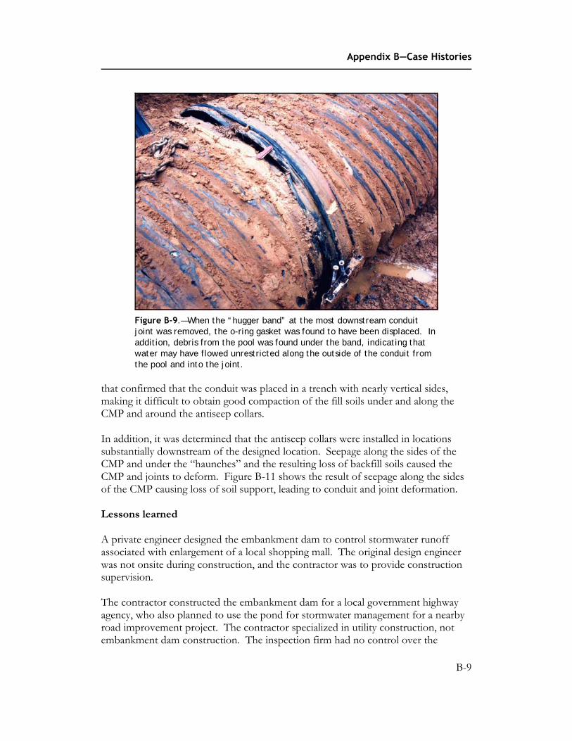
Figure B-9.—When the “hugger band” at the most downstream conduit joint was removed, the o-ring gasket was found to have been displaced. In addition, debris from the pool was found under the band, indicating that water may have flowed unrestricted along the outside of the conduit from the pool and into the joint.
that confirmed that the conduit was placed in a trench with nearly vertical sides, making it difficult to obtain good compaction of the fill soils under and along the CMP and around the antiseep collars.
In addition, it was determined that the antiseep collars were installed in locations substantially downstream of the designed location. Seepage along the sides of the CMP and under the “haunches” and the resulting loss of backfill soils caused the CMP and joints to deform. Figure B-11 shows the result of seepage along the sides of the CMP causing loss of soil support, leading to conduit and joint deformation.
Lessons learned
A private engineer designed the embankment dam to control stormwater runoff associated with enlargement of a local shopping mall. The original design engineer was not onsite during construction, and the contractor was to provide construction supervision.
The contractor constructed the embankment dam for a local government highway agency, who also planned to use the pond for stormwater management for a nearby road improvement project. The contractor specialized in utility construction, not embankment dam construction. The inspection firm had no control over the
B-9

Conduits through Embankment Dams
Figure B-10.—The presence of undisturbed foundation soils confirmed that the conduit was placed in a trench with nearly vertical sides, making it difficult to obtain good compaction of the fill soils under and along the CMP and around the antiseep collars.
Figure B-11.—Seepage along the sides of the CMP resulted in loss of soil support, causing conduit and joint deformation.
B-10

Appendix B—Case Histories
project, and served only to document the placement of earthfill and compaction. The local government agency overseeing the project was a highway department, which had little dam construction experience.
The embankment dam was completely removed, and a new embankment dam and concrete spillway conduit were constructed 2 years later in the same location. When the foundation for the new dam was being prepared, the State inspector observed roots and other debris, under the original embankment fill. Since such material should have been removed, this reinforces the notion that supervision of embankment dam construction by qualified engineers is essential. After reconstructing the embankment dam, the owner eventually decided not to pursue legal action to determine fault. The original contractor went bankrupt just before the failure occurred, the local government may have incurred some liability for overseeing the construction, and the design was apparently completed in accordance with the approved standards in place at the time the design was started. (Although more restrictive standards requiring different conduit joints had been developed before the original embankment dam was constructed, the design approval was apparently “grandfathered” under the older standard.)
The failure resulted in new requirements that spillway conduits not be installed into near-vertical trenches excavated into the foundation or partially completed embankment dam. This trench installation technique is common procedure for highway culverts, because the sides of the trench facilitate “arching” of the backfill, reducing the load on the culvert. However, this results in areas of low soil pressure along the conduit, facilitating seepage along the conduit. Filters are now routinely constructed around the downstream portion of the conduit to intercept this type of flow and prevent internal erosion. In addition, the use of large diameter flexible conduits for embankment dam spillways has been substantially reduced in the last 10 years because of this and other failures related to large deformations, difficulty in obtaining watertight joints, and difficulty placing earthfill under the sides of the conduits (Van Aller, 1993).
References
State of Maryland, Dam Safety Division, unpublished investigation notes and file photographs (MD Dam No. 372). The reports of the forensic investigation were not submitted to the State and are not public information.
Van Aller, Recent Failures of Large Corrugated Metal Pipe Spillways, ASDSO 1993 Annual Conference, 1993.
B-11

Conduits through Embankment Dams
Project name: Arkabutla Dam
Location: Mississippi
Summary: Construction error leads to defective joints in an outlet works conduit
Arkabutla Dam is an embankment dam located in northwest Mississippi on the Coldwater River (figure B-12).
The USACE designed the embankment dam for the purpose of flood control. The embankment dam was completed in 1943 and is 83 feet high, 10,000 feet long, and controls a drainage area of approximately 1,000 square miles. Runoff from the drainage area is stored in the lake created by the embankment dam, and the water is released at a controlled rate through a gated intake structure located in the lake. Water passing through the control structure is released to the downstream river channel through an egg-shaped reinforced concrete conduit. The conduit is 325 feet long, 18.25 feet high, and 16 feet wide, and the sides of the conduit are 42 inches thick. At spillway crest, the embankment dam has a storage capacity of 525,000 acre-feet.
Arkabutla Dam is constructed across a broad alluvial valley. The intake structure is located in the reservoir in the alluvial valley, not in the abutment. The clay top stratum was removed and the intake structure, conduit, and stilling basin are founded on alluvial sands. Since the conduit is founded on sand, it was imperative that the
Figure B-12.—Arial view of Arkabutla Dam, Mississippi.
B-12

Appendix B—Case Histories
waterstops in the joints of the conduit be designed and installed properly. Unfortunately, this did not happen. There is no written record why this error was not discovered sooner. A cross section of the outlet works conduit is shown in figure B-13. The designers intended that the lower one-third of the conduit be constructed as one continuous monolith. Above the field joint shown in figure B-13, the conduit was designed to be cast in 25-foot long monoliths.
At each monolith joint, a rubber waterstop was placed in the top two-thirds of the conduit. The waterstop was placed in the center of the conduit walls and extended from 2 feet below the field joint on one side of the conduit to 2 feet below the field joint on the other side. No waterstop was installed along the lower one-third of the conduit, but the contractor also constructed the lower one-third of the conduit monolithically. This was not the design intent. With no waterstop along the bottom of the conduit, the very fine sand in the foundation was eroded through each joint and was continually being flushed downstream during operation of the outlet works.
Problems with the joints were discovered soon after the project went into operation. Lead wool was used for several years to control the erosion of fine sand into the conduit, but problems were experienced in keeping the lead wool in the joints. The designers estimated that the maximum settlement of the conduit would eventually be 0.25 feet. However, by 1950, the conduit had settled as much as 0.75 feet. Much of this unexpected settlement was attributed to the loss of sand through the joints of the conduit. The first attempt to grout the joints was undertaken in 1950. Grout “takes” were not significant in 1950, except at joints 5-6 and 6-7, where 47 and 98 cubic feet of grout, respectively, were pumped. There are 13 monoliths, with monolith 1-2 being at the upstream transition and monolith 12-13 being at the downstream end of the conduit. Monolith 6-7 is about 60 feet downstream of the centerline of the embankment dam. Monolith 4-5 is about 10 feet downstream of centerline of dam. Additional settlements since 1950 have been less than 1 inch; however, in 1970 an attempt to grout the joints again was made due to sand being eroded into the conduit through joints. Water and trace amounts of sand were again noted coming from some joints in 1977, but attempts to grout the joints resulted in only insignificant amounts of grout “take.” Since 1977, at least three attempts have been made to stop water coming from the joints using chemical grout. Grout takes were significant only at joints 3-4, 5-6, and 6-7, where 410, 33, and 68 cubic feet of grout, respectively, were placed. Joints 3-4, 5-6, and 6-7 have caused the most trouble, but essentially all joints have had to be grouted at least once with either chemical grout or neat cement grout.
The above background provides an introduction to the problem experienced in the fall of 2003. While in the conduit to replace the filler in the outer dove-tail portion of the joints, joint 6-7 broke lose and started to make sand at a significant rate (2/3
cubic yard in 1 hour). Even though it has been known since construction that there were no waterstops in the lower portion of the conduit, it was thought that the joints
B-13

1" dia. bars, 2'0" c.c. 1" dia. bars, 10" c.c.
5/8" dia. stirrups, legs 1'-4" c.c.
Field joint
1" dia. bars, 8" c.c
longitudinally, hook at bottom
1 1/8" dia. bars, 8" c.c.
1'8" 1'6"
4'3"
Conduits through Embankment Dams
Figure B-13.—Cross section of the outlet works conduit.
had been satisfactorily sealed with grout and that periodic grouting with chemical grout would keep the conduit watertight. However, since joint 6-7 broke lose suddenly and flowed sand at a significant rate, the conduit could no longer be considered safe for static loading and definitely could not be considered safe for earthquake loadings. Therefore, a team was formed to determine what should or could be done to ensure the continued safety of the conduit. The team solicited advice from personnel throughout the USACE. The consensus felt that the obvious solution was to line the conduit with a steel liner. However, the team recognized that this would be very expensive and would require bypassing outflow. Also, going through the design process, review process, and budgeting process would take several years. Therefore, the team elected to experiment with an interim measure that may or may not be the final solution. The team felt that if a plate were bolted across the joint with gasket material beneath it to prevent sand from exiting from the joint, then this would solve the problem. However, no one had any experience in doing this, and there was no assurance that the plate would stay in place. Therefore, the USACE elected to experiment with two joints during the time that the structure was unwatered for the 5-year formal inspection. A metal plate was bolted across joints 5-6 and 6-7 during a shutdown of the outlet works (figure B-14).
The following gives a brief outline of what was done:
• Cement mortar.—Cement mortar was used to smooth the surface across the joint. This mortar was from 1.8 inches thick to 1 inch thick (had this much differential settlement at one joint).
• Steel plate.—Twenty-two feet of stainless steel plate was installed along the bottom of the joint. At a distance of about 10.5 feet from the centerline of the conduit, a 1.25-inch diameter hole was drilled in the side of the conduit to the existing waterstop (about 21 inches).
B-14

Appendix B—Case Histories
Figure B-14.—Metal plate bolted across the joint.
• Waterstop.—A waterstop was formed in this hole using backer rod saturated with chemical grout.
• Chemical grout.—After chemical grout in the backer rod had hardened, chemical grout was pumped through a tube that had been installed to the bottom of the hole. Grout was pumped under pressure to fill any voids and try to get a good contact with the rubber waterstop.
• Anchors.—The metal plate was designed to have metal straps hold it down. The metal straps were anchored to the conduit with stainless steel anchors installed 4 inches deep. Anchor straps were installed on 1-foot centers. Therefore, 46 holes had to be drilled at each installation. A two-part epoxy was used to hold the anchors in place.
• Fabric.—Two layers on engineering fabric were installed at each joint.
• Compressible rubber.—A 1.25-inch thick layer of compressible rubber was installed about 2 inches from the joint on each side of the joint.
• Additional steel plates.—A 1/8-inch stainless steel plate 36 inches wide was installed on top of everything. Several holes had been previously drilled in this plate along its centerline to let any water that seeped up along the joint pass
B-15

Conduits through Embankment Dams
through the filter fabric and out through the holes without building up pressure under the plate.
• Metal straps.—The metal straps 3/8 inch thick and 3 inches wide were then bolted across the plate, compressing the material and producing a slight bow in the plate.
• Outer edges.—The outer edges of the plate were then sealed to temporarily hold the cement grout in place. This grout was placed between the steel plate and the engineering fabric. No grout was placed between the two rubber seals, so that any seepage along the joint could pass through the fabric and not build up pressure. This was done to give the plate solid support to help minimize vibrations.
After installation, the project released 1,500 ft3/s for 2 weeks and then inspected the joint. The inspection team found the plate at one of the two repair joints displaced, bent, and torn (figure B-15).
As of September 2004, the USACE had yet to determine why the patch did not stay in place and can only speculate that a log may have hit it. Currently, the USACE is evaluating installation of a steel liner as the only reliable solution for the defective joints.
Figure B-15.—Damaged metal plate.
B-16

Appendix B—Case Histories
Lessons learned
Close construction oversight is required for constructing conduits through embankment dams. Repair efforts are not always successful, and complete renovation may be required.
Reference
USACE project files and periodic inspection reports.
B-17

Conduits through Embankment Dams
Project name: Balman Reservoir Dam
Location: Colorado
Summary: Reservoir evacuation by pumping and controlled breaching techniques
Balman Reservoir Dam is an earthfill embankment dam located in San Isabel National Forest in south central Colorado near Cotopaxi and is owned by the U.S. Forest Service. The embankment dam has a maximum height of 31 feet with a crest length of 75 feet and impounds approximately 51 acre-feet of water. The embankment dam was constructed at approximately elevation 9,400 feet and is located in a remote area. The embankment dam has a small earthcut, 12-foot wide spillway and no gated outlet works. The embankment dam was built in 1965.
On November 4, 1996, a large sinkhole was discovered on the upstream slope and crest of the embankment dam. The sinkhole was measured to be approximately 8 to 10 feet in diameter and approximately 6 to 8 feet deep. A small whirlpool was observed in the reservoir near the sinkhole, indicating the presence of continual flow into the cavity and apparent sediment transport into the sinkhole. Cracks were developing in the embankment dam crest above the sinkhole (figure B-16) and sloughing of the embankment materials into the sinkhole was observed. Extensive water flow was occurring all along the downstream toe of the embankment dam and along the right abutment groin up to approximately mid-height of the dam. Water exiting the slope was also occurring on the downstream face above an 18-inch diameter drainpipe for the chimney drain.
After reviewing the original construction plans for the embankment dam and taking into account its past poor operational performance and the worsening condition of the sinkhole and dam, it was apparent that the dam was experiencing an internal erosion failure, which could eventually result in a sudden and catastrophic breach of the dam and a release of the reservoir. The downstream hazard consists of a church camp, a hiking trail, a campground, and a county road. Based on this, it was decided that the reservoir needed to be lowered to a safe storage level and to a level where no more seepage was exiting on the downstream face of the dam and along the downstream toe. Since the embankment dam lacked an outlet works, it was decided to try lowering the reservoir by an alternative means.
The first attempt to lower the reservoir water surface to a safe level was made by diverting the reservoir inflow away from the reservoir. The diversion structure above Rainbow Lake, located upstream of Balman Reservoir, was adjusted on November 8, 1996 to direct all flows from the drainage basin into Rainbow Lake and away from Balman Reservoir in the hope that this would help lower the water
B-18

Appendix B—Case Histories
Figure B-16.—Cracking at the embankment dam crest above the sinkhole on the upstream slope of the embankment dam. Note the simple staking of the area to monitor movement of the crack.
surface level of Balman Reservoir. After five days of diverting the water, the water surface level in Balman Reservoir was lowered only approximately 1 to 2 inches, and the reservoir level remained just below the spillway crest. At this rate, the reservoir could not be drawn down in a reasonable period of time and be maintained at a safe level. Therefore, it was decided to partially breach the embankment dam.
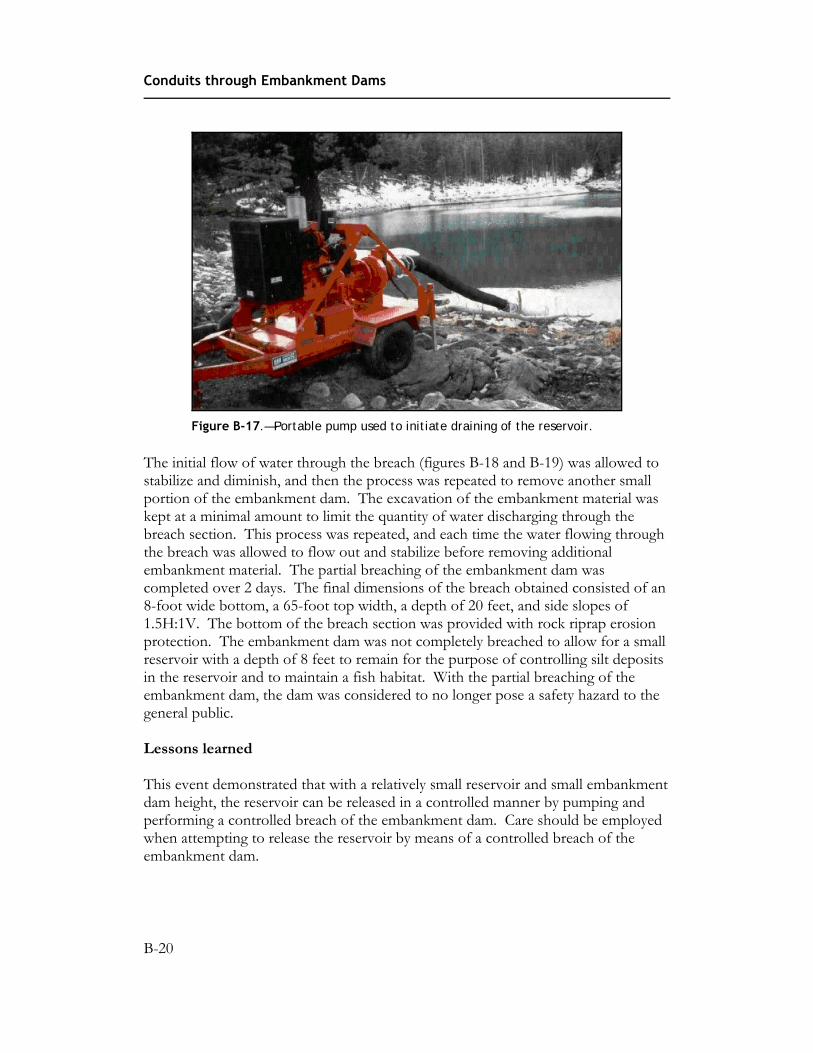
On November 15, 1996, a portable 3,000 gal/min pump (figure B-17) was delivered to the site. The pump was set up adjacent to the spillway and placed into operation. The pump was operated continuously for 3 days, and the water surface level of the reservoir was lowered to approximately 8 feet below the spillway crest. At this point, the excavation to breach the embankment dam was commenced. A Caterpillar 330 track-mounted excavator was used to perform the excavation. The area of the sinkhole and the upstream slope were first excavated as far into the reservoir as the excavator could reach, and then the embankment dam crest was benched down approximately 4 feet on either side of the breach. The breach was excavated on both sides at a slope of 1.5H:1V down to the water surface level. Rocks of varying sizes were placed in the bottom of the excavation and down the downstream slope of the embankment dam to help control erosion. Then, a small amount of the embankment dam was removed from the breach entrance, and water was allowed to flow through the breached section. Some minor slope erosion occurred, but no backcutting of the channel into the embankment dam was observed.
B-19
Conduits through Embankment Dams
Figure B-17.—Portable pump used to initiate draining of the reservoir.
The initial flow of water through the breach (figures B-18 and B-19) was allowed to stabilize and diminish, and then the process was repeated to remove another small portion of the embankment dam. The excavation of the embankment material was kept at a minimal amount to limit the quantity of water discharging through the breach section. This process was repeated, and each time the water flowing through the breach was allowed to flow out and stabilize before removing additional embankment material. The partial breaching of the embankment dam was completed over 2 days. The final dimensions of the breach obtained consisted of an 8-foot wide bottom, a 65-foot top width, a depth of 20 feet, and side slopes of 1.5H:1V. The bottom of the breach section was provided with rock riprap erosion protection. The embankment dam was not completely breached to allow for a small reservoir with a depth of 8 feet to remain for the purpose of controlling silt deposits in the reservoir and to maintain a fish habitat. With the partial breaching of the embankment dam, the dam was considered to no longer pose a safety hazard to the general public.
Lessons learned
This event demonstrated that with a relatively small reservoir and small embankment dam height, the reservoir can be released in a controlled manner by pumping and performing a controlled breach of the embankment dam. Care should be employed when attempting to release the reservoir by means of a controlled breach of the embankment dam.
B-20

Appendix B—Case Histories
Figure B-18.—Initialization of the breach in the embankment dam near the left abutment.
Figure B-19.—Discharge of water through partially breached section and down the downstream slope of the embankment dam.
Reference
Colorado Division of Water Resources, Dam Safety Engineers Inspection Report Files—Incident Report for Balman Reservoir Dam, State Engineers Office, Dam Safety Branch, 1996.
B-21

Conduits through Embankment Dams
Project name: Beltzville Dam
Location: Pennsylvania
Summary: Conduit crack survey
Beltzville Dam is located in northeastern Pennsylvania. The embankment dam has a structural height of 170 feet, a crest length of 4,560 feet, and a crest width of 30 feet. Appurtenant features include a spillway and an outlet works. The outlet works is used for flood control. The outlet works consists of a gated intake structure, a 7-foot diameter concrete conduit approximately 1,165 feet in length, and a stilling basin. The USACE with assistance from the Beltzville Lake operations personnel performed a condition survey (also called a crack survey) of the outlet works conduit in July 2003. Previous formal surveys had taken place in 1971, 1988, 1992, and 1999. Although not specifically meeting all of the parameters defining a confined space, the outlet conduit was treated as such for man-entry. Personnel were trained in confined space operations and air monitoring equipment, and a hard-wire communications tool was used during the survey. Drawings showing that the results of the previous surveys were used as a baseline for performing the current mapping. Stationing within the conduit is marked periodically on the conduit walls, although some markings have lessened in intensity. Digital photographs were taken of some of the more prominent features.
Spalling had occurred at joints and other localized spots. Minor cracking, spalling, surface abrasion, and calcitic efflorescence were observed and mapped. Figures B-20 through B-23 are typical of these features. No major leakage was evident; however, minor seepage of water was observed in two locations but with no material being carried.
The 2003 survey noted changes in the sizes of some of the spalls and seven additional (or not-previously-mapped) spalls. Two new (or not-previously-mapped) occurrences of cracking and three new (or not-previously-mapped) occurrences of calcitic efflorescence were observed. Conversely, calcitic efflorescence no longer existed in six locations where it had been previously mapped. Flow through the conduit during high releases appeared to have removed these materials. In general, the condition of the conduit had changed little from the 1999 survey. A comparison of photos taken in 1999 and 2003 also indicated little change in the more prominent features. Drawings showing the features are developed after each survey is completed using different colors to denote the different surveys in order to follow changes in condition of the conduit.
B-22

Appendix B—Case Histories
Figure B-20.—Large spall at the construction joint located at station 12+13.
Figure B-21.—Exposed aggregate located at station 11+28.
B-23

Conduits through Embankment Dams
Figure B-22.—Popout located at station 10+79.
Figure B-23.—Spall at the construction joint located at station 4+93.
B-24

Appendix B—Case Histories
The conduit is considered to be in a continued serviceable condition. Some new or increased instances of spalling, cracking, and efflorescence are apparent. Several instances of efflorescence were no longer apparent. No material is being carried with the existing minor seeping flows observed. The next conduit condition survey is scheduled for 2008 in conjunction with the next periodic inspection of the project.
Lessons learned
• Periodic conduit condition surveys and walkthroughs are essential for thorough dam safety monitoring.
• Use of different colors for different surveys in the drawings enhances interpretation of the condition of the conduit and allows for comparison with the results of previous inspections.
Reference
U.S. Army Corps of Engineers, Engineering Regulation 1110-2-100, Periodic Inspection and Continuing Evaluation of Completed Civil Works Structures, 1995.
B-25

Conduits through Embankment Dams
Project name: Bohemia Mill Dam
Location: Maryland
Summary: Undermining and failure of a new spillway conduit constructed on piles
The Bohemia Mill Dam is a very old structure, constructed in the early 1900s with a timber spillway structure supported on piles. The embankment dam is about 15 feet high with a two-lane county road on the crest. In the 1990s, deterioration of the timber bridge over the spillway led the county to enact weight restrictions and restrict traffic to a single lane until a new structure could be designed and built.
Geotechnical investigations of the embankment dam and foundation revealed that the underlying soils are very soft, and a decision was made to replace the spillway with a reinforced cast-in-place box culvert supported on 60-foot long steel piles. Seepage control along the culvert was to be provided by a bentonite slurry wall near the center of the embankment dam and by a filter drain at the downstream end.
Construction of the new spillway, slurry cutoff wall, filters, and new lake drain was completed in 2002 (figures B-24 and B-25).
In early 2004, an engineer inspecting the bridge notified the owner that he observed clear seepage from under the downstream end of the spillway conduit, but there was no indication of internal erosion or backward erosion piping of the embankment or foundation soils.
However, within a few months, a sinkhole was noted in the pavement on the embankment dam crest (figure B-26). The seepage flow had significantly increased, and soil particles were observed moving downstream. The condition rapidly worsened, and the size of the sinkhole increased (figure B-27). Particles of the bentonite slurry cutoff wall were observed to be washing downstream from an area that appeared to be boiling (figure B-28). Attempts to create a sandbag weir around the boil to reduce leakage under the spillway conduit were unsuccessful, and the lake was drained.
Currently, the structure has not been repaired. Repair options under consideration include construction of a jet grout slurry wall along the upstream side of the embankment dam and spillway or installation of sheetpile cutoff wall along the upstream side of the dam and culvert.
B-26

Appendix B—Case Histories
Figure B-24.—Because of soft foundation soils, numerous 60-foot long pipe piles were installed in winter 2001 to support a new reinforced cast-in-place concrete spillway structure.
Figure B-25.—This the downstream end of the spillway at the end of construction in 2002.
B-27

Conduits through Embankment Dams
Figure B-26.—Less than 2 years later, an engineer inspecting the bridge over the spillway reported that seepage flow was visible from under the downstream end of the spillway. The seepage flow was clear, and no migration of soils was evident. A few months later, the roadway on the dam crest collapsed, and large quantities of sediment were observed in the pool below the dam.
Figure B-27.—The road was closed immediately, and lake level was lowered. However, the sinkhole rapidly enlarged.
B-28

Appendix B—Case Histories
Figure B-28.—Seepage flow at the downstream end of the spillway appeared to be boiling. Attempts to create a sandbag weir around the boil to reduce leakage under the spillway were unsuccessful.
Lessons learned
Avoid constructing conduits on piles, because the conduit may become undermined, allowing uncontrolled seepage to occur under it.
Reference
Maryland Dam Safety Division, dam file No. 158
B-29
Conduits through Embankment Dams
Project name: Clair Peak Dam
Location: Maryland
Summary: Grouting from the embankment dam surface to fill voids along the outside of a spillway conduit
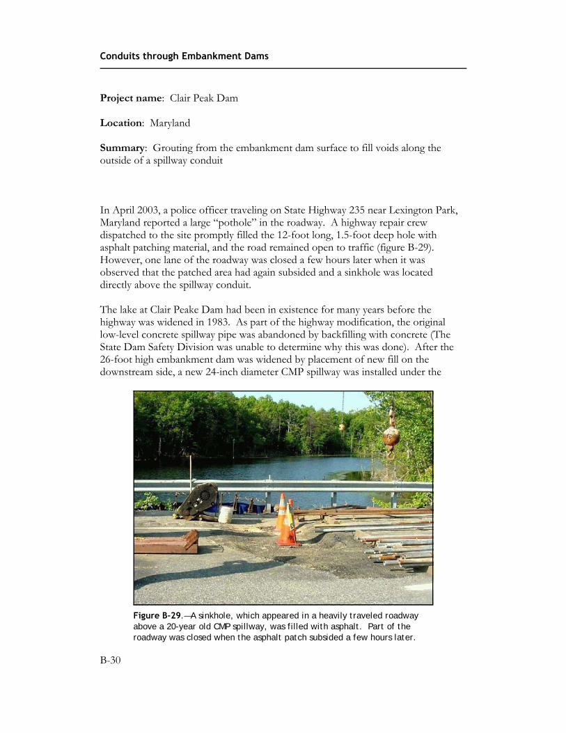
In April 2003, a police officer traveling on State Highway 235 near Lexington Park, Maryland reported a large “pothole” in the roadway. A highway repair crew dispatched to the site promptly filled the 12-foot long, 1.5-foot deep hole with asphalt patching material, and the road remained open to traffic (figure B-29). However, one lane of the roadway was closed a few hours later when it was observed that the patched area had again subsided and a sinkhole was located directly above the spillway conduit.
The lake at Clair Peake Dam had been in existence for many years before the highway was widened in 1983. As part of the highway modification, the original low-level concrete spillway pipe was abandoned by backfilling with concrete (The State Dam Safety Division was unable to determine why this was done). After the 26-foot high embankment dam was widened by placement of new fill on the downstream side, a new 24-inch diameter CMP spillway was installed under the
Figure B-29.—A sinkhole, which appeared in a heavily traveled roadway above a 20-year old CMP spillway, was filled with asphalt. Part of the roadway was closed when the asphalt patch subsided a few hours later.
B-30

Appendix B—Case Histories
roadway. The new pipe was installed on a steep slope completely through the new and old embankment zones, with the upstream end of the pipe set at the normal pool elevation and the downstream end at the toe of the new earthfill.
An inspection of the embankment dam in 1996 noted some “sinkholes” in the downstream slope of the embankment near the location of the pipe, but no repairs were made. Another inspection of the embankment dam and pipe exterior the following year noted substantial deposits of sediment in the stream channel just below the downstream end of the pipe. An interior evaluation of the pipe could not be made, because the sediment deposits at the downstream end obscured the pipe, and debris placed at the upstream end by a local beaver precluded inspection at the upstream end.
After the roadway collapsed in 2003, an inspection revealed extensive deterioration of the CMP and that substantial loss of embankment material had occurred. Ground penetrating radar (GPR) detected large voids in the embankment along the pipe, and a decision was made to construct a new spillway at a different location (figures B-30 and B-31). The failed CMP spillway and adjacent voids were filled with a stiff cement and flyash-based “compaction grout” (figure B-32). A specialty contractor performed the grouting and pumped the grout into the 24-inch diameter CMP using a trailer mounted, diesel powered, piston type concrete pump, specially mounted for grout injection work. The pipe fill mixture was a flowable, nonshrink, moderate strength (500-700 lb/in2) grout with the following specifications:
• 600 pounds type I Portland cement
• 500 pounds flyash
• 500 pounds pea gravel
• 1800 pounds concrete sand
• 40 to 45 gallons of water
• 40 ounces of superplastizer
The compaction grouting to fill the voids in the embankment dam was performed from the roadway and median along the abandoned pipe alignment, with each grout pipe extending to approximately the pipe invert elevation. The grout-hole layout plan consisted of 128 compaction grout locations based on a 5-foot offset square grid throughout the anticipated treatment zone. The compaction grouting was performed utilizing a diesel powered track drill to install the grout casing through the pavement and fill soils to the invert elevation of the pipe. The grout was a blend of
B-31

Conduits through Embankment Dams
Figure B-30.—Ground penetrating radar investigations were performed from the embankment dam crest.
Figure B-31.—Ground penetrating radar identified the location of voids along the CMP.
concrete sand, type I Portland cement, flyash, and water proportional to provide a pumpable mix with about 500 lb/in2 strength in 28 days. The compaction grout mixture specifications are as follows:
• 200 pounds of Type I Portland cement
• 850 pounds of flyash
B-32

Appendix B—Case Histories
Figure B-32.—The failed CMP and voids were filled with a stiff compaction grout.
• 2300 pounds of concrete sand
• 35 gallons of water per cubic yard
During compaction grouting, vertical ground movements were monitored and recorded. A surveyor’s level was being utilized to monitor the vertical ground movements. The system used was capable of detecting 1/8-inch movements. The slump of the grout was required to be maintained at 2 inches or less.
A filter diaphragm surrounding both the CMP spillway and the abandoned concrete pipe was constructed near the downstream toe of the embankment dam to intercept and control any seepage along the outside of the conduits.
Lessons learned
Compaction grouting may be satisfactorily used to fill voids existing along a spillway conduit, when conventional excavation cannot remove the conduit.
Reference
Maryland Dam Safety Division, dam file No. 275.
B-33
Conduits through Embankment Dams
Project name: Como Dam
Location: Montana
Summary: Sliplining of an existing outlet works conduit using a steel pipe slipliner
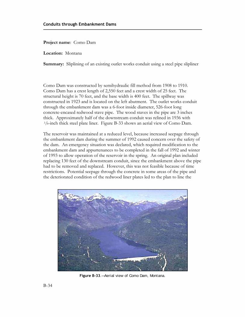
Como Dam was constructed by semihydraulic fill method from 1908 to 1910. Como Dam has a crest length of 2,550 feet and a crest width of 25 feet. The structural height is 70 feet, and the base width is 400 feet. The spillway was constructed in 1923 and is located on the left abutment. The outlet works conduit through the embankment dam was a 6-foot inside diameter, 526-foot long concrete-encased redwood stave pipe. The wood staves in the pipe are 3 inches thick. Approximately half of the downstream conduit was relined in 1936 with 3/8-inch thick steel plate liner. Figure B-33 shows an aerial view of Como Dam.
The reservoir was maintained at a reduced level, because increased seepage through the embankment dam during the summer of 1992 caused concern over the safety of the dam. An emergency situation was declared, which required modification to the embankment dam and appurtenances to be completed in the fall of 1992 and winter of 1993 to allow operation of the reservoir in the spring. An original plan included replacing 130 feet of the downstream conduit, since the embankment above the pipe had to be removed and replaced. However, this was not feasible because of time restrictions. Potential seepage through the concrete in some areas of the pipe and the deteriorated condition of the redwood liner plates led to the plan to line the
Figure B-33.—Aerial view of Como Dam, Montana.
B-34

Appendix B—Case Histories
entire conduit with a steel pipe slipliner. This steel pipe slipliner would provide additional structural stability and a good flow surface, prevent seepage through the concrete, and could be placed in an expeditious manner to allow reservoir operation in the spring of 1993.
The existing redwood liner was removed from the inside of the concrete conduit, upstream and downstream of the gate chamber. A 66-inch diameter steel pipe slipliner (figure B-34) was placed inside the existing concrete conduit, upstream and downstream of the gate chamber. The steel pipe slipliner was placed in 20-foot sections. These sections were pulled into place, and the ends were butt strapped and welded. The voids between the steel pipe slipliner and the concrete conduit were then grouted through grout plugs in the steel pipe slipliner. This work (about 300 feet of pipe) was completed in about 1 month. A new transition structure was placed between the conduit and the terminal structure. Also, the exit channel was modified by placing grouted riprap for about 150 feet downstream of the terminal structure.
Lessons learned
Rapid installation of a steel pipe slipliner can be done to facilitate reservoir operations.
Figure B-34.—Installing the steel pipe slipliner within the existing outlet works conduit.
B-35

Conduits through Embankment Dams
Reference
Bureau of Reclamation project files.
B-36

Appendix B—Case Histories
Project name: Crossgate Dam
Location: North Carolina
Summary: Problems encountered during the construction of a new siphon spillway
Crossgate Dam was constructed in 1955 in a rural area outside of Raleigh, North Carolina. The site was eventually incorporated into the Raleigh city limits, and development in the area downstream of the 25-foot high embankment dam resulted in a high hazard classification. Very little maintenance was performed on the embankment dam after it was constructed, and 40 years of neglect took its toll on the dam and the CMP spillway conduits.
In 1996, a developer agreed to upgrade the embankment dam in order to build new homes around the reservoir. A new 12-inch diameter siphon spillway was designed to be installed in a trench excavated through the embankment dam crest (see figure B-35). Leumas (1998, p. 710) discussed the design of the siphon:
The design for the siphon was somewhat unique in that it served not only as a normal pool regulating device which discharged water from the surface of the reservoir, but also as a “bottom drain” structure which could drain the reservoir by discharging flow from near the bottom of the reservoir. Also, the siphon was designed to be self-priming, so that it would not need to be filled initially to start the siphon in order to drain the reservoir.
Unfortunately, a hurricane arrived during construction of the siphon and proved disastrous. The CMPs, which served as the only spillway, had already been abandoned with grout, and the only outflow was by means of a small, temporary siphon installed by the contractor. The flood overtopped the embankment dam, and
Figure B-35.—A well designed siphon was to be installed through the dam crest (from Leumas, 1998).
B-37

Conduits through Embankment Dams
erosion severely damaged the partially constructed siphon. Temporary repairs were under way a few days later, but not yet completed, when another storm caused the embankment dam to again be overtopped. Erosion of the embankment dam, at the location of the siphon, by the second storm event caused the embankment dam to breach.
A decision was made to abandon the siphon spillway and instead construct a concrete riser and barrel structure. However, the siphon was later repaired and was successfully used to drain the reservoir (although several large pumps were also required).
Lessons learned (after Leumas, 1998)
• A siphon may be an attractive option for providing an existing embankment dam with a permanent means to drain a reservoir in lieu of excavation of the embankment to install a traditional bottom drain. However, many design elements should be considered in deciding whether to install a siphon, a low level outlet works, or sliplining the existing deteriorated conduit. Each method has its own advantages and disadvantages. The long term performance of the final selection and public safety considerations, rather than cost, should be the basis for the selected design.
• Diversion during construction is a vital element to be considered in the design process. An acceptable level of risk for diversion requirements, which balances economics for the project and an owner’s liability, must not compromise the safety of the downstream public.
• Bad weather can occur during any project. Contingency planning should be made during the design process, which addresses what to do in the event that the capacity of diversion measures is exceeded. Such planning should have a readily available notification list of State dam safety program staff, emergency management officials, and other State and local representatives, who can assist in the event of an emergency.
Reference
Leumas, James, To Siphon or Not To Siphon: That is the Question (Among Others)—A Repair History of the Crossgate Dam, 1998 ASDSO Annual Conference, Las Vegas, 1998.
B-38

Appendix B—Case Histories
Project name: Dalewood Shores Dam
Location: Mississippi
Summary: Man-entry inspection of a deteriorated corrugated metal outlet works conduit
Dalewood Shores Dam was constructed in 1960 near Lauderdale, Mississippi without benefit of a qualified professional engineer. The 34-foot high embankment dam has a crest length of 3,800 feet and impounds a surface area of roughly 1,000 acres at normal pool elevation. Normal outflow occurs by way of a concrete chute spillway. Due to downstream development, the embankment dam is now classified as a high hazard structure.
During construction, a 60-inch CMP conduit with an upstream flap gate was installed through the embankment dam as a means to lower the reservoir level. The flap gate failed the first time it was operated, and the owner abandoned the outlet
works by covering the intake and gate with soil and rock to prevent loss of the reservoir.
Subsequent sloughing of the upstream slope damaged the upstream end of the CMP. An man-entry inspection of the pipe in 1993 noted that the pipe had ruptured, and seepage into the conduit was observed at two locations. At that time, the seepage flow was clear, and no soil loss was evident. However, by 1995 the seepage flow had increased, and soil deposits in the pipe indicated that internal erosion or backward erosion piping of embankment material was occurring, and failure of the embankment dam was a distinct possibility. Figure B-36 shows the man-entry inspection being performed. Due to the potential for loss of life if the embankment dam were to fail, the State dam safety agency directed the owner to hire a professional engineer to develop remedial plans to immediately repair the dam.
Figure B-36.—A man-entry inspection of this 60-inch CMP noted seepage and extensive loss of embankment soil at two locations.
B-39
Conduits through Embankment Dams
Although all previous man-entry inspections had noted that the seepage into the CMP was clear, the accumulation of soil in the conduit indicated that material was being transported into the conduit. Until remedial repairs could be made, the engineer made frequent man-entry inspections of the conduit in order to take emergency action, if dam failure was imminent. A decision was made to slipline the existing CMP with a 48-inch outside-diameter HDPE pipe and then grout the annulus between the pipes. The HDPE pipe joints were fusion welded in the field. A filter diaphragm was constructed downstream around the downstream end of the existing conduit to control seepage along the outside of the conduit. The work was completed in 1996 at a total cost of about $140,000.
Lessons learned
• Internal erosion or backward erosion piping of embankment material may occur in an embankment dam, even if seepage appears clear during infrequent inspections.
• CMP is a poor choice for use in outlet works conduits through an embankment dam.
• Sliplining a 60-inch CMP with 48-inch outside-diameter HDPE was costeffective.
References
Newhouse, Scott, and Dan McGill, This Old Dam: Must It Have Outlet Works?, 1997 ASDSO Annual Conference Proceedings, Pittsburgh, Pennsylvania, 1997.
Clevenger, Charles, Dalewood Shores Dam Conduit Repair, FEMA/ICODS Dam Safety Seminar No. 6, Piping Associated with Conduits through Embankment Dams, 1999.
B-40
Appendix B—Case Histories
Project name: Empire Dam
Location: Colorado
Summary: Reservoir evacuation using controlled breaching techniques
Empire Dam is an earthfill embankment dam located in San Isabel National Forest in central Colorado near Leadville and is privately owned. The embankment dam has a maximum height of approximately 10 feet with a crest length of 100 feet and impounds approximately 80 acre-feet of water above the natural ground surface. The embankment dam was constructed at approximately elevation 11,000 feet and is located in a remote area with limited access consisting of a very rough 4-wheel drive access road. The embankment dam was provided with a small earthcut spillway and a gated outlet works. The outlet works, however, was found to be inoperable. Records showed the embankment dam to be fairly old and was constructed to enlarge the storage of a natural high altitude lake.
On June 27, 1997, a backpacker reported that the embankment dam was being overtopped, and a considerable amount of erosion damage was occurring on the downstream slope of the dam. The backpacker was concerned that the dam may fail and indicated that a 2-hour hike is required to reach the site.
An investigation of the damsite revealed that the embankment dam had been overtopped, but was not being overtopped at the time of the inspection. On the day of the inspection, the reservoir was at a level of approximately 2.5 feet below the dam crest. A large scarp and eroded area was noted on the downstream slope and dam crest, where the embankment dam had been overtopped (figure B-37). The scarp was eroded approximately 3 feet into the dam crest. Approximately 0.5 ft3/s of seepage was exiting from the bottom of the scarp area, and the discharge was clear. The flow into the reservoir was estimated to be approximately equal to the seepage through the erosional scarp. The embankment dam did not appear to be in imminent danger of failure, but the erosion of materials through the scarp and the reduced section of the embankment dam would eventually lead to a failure of the dam.
The downstream hazard consisted of one residence located approximately 2 miles downstream of the embankment dam at an elevation approximately 1,500 feet lower than the dam. A failure of the embankment dam would release approximately 80 acre-feet of water into a very narrow and steep natural channel for approximately 0.5 mile downstream of the dam, at which point the channel grade lessens and the
B-41

Conduits through Embankment Dams
Figure B-37.—Erosion scarp on downstream slope of the embankment dam at the location of the overtopping of the dam crest.
channel widens significantly. The dam break flood would attenuate rapidly at this point; however, the flood would still pose a threat to the one home and anyone fishing and hiking in or along the stream channel. With the long Independence Day weekend approaching, it was anticipated that heavy recreational use in the area could be expected, and the embankment dam in its present condition posed a real threat to the safety of the general public.
Several futile attempts were made to operate the outlet works. Since the outlet works was inoperable, it was decided to perform a controlled breach of the embankment dam down to a safe level. After some discussion concerning the relative difficulty in getting heavy equipment to the damsite, and the significant environmental damage that would ensue, it was suggested that it would not take all that much effort to perform a controlled breach using manual labor. Prison inmates had been used previously to perform routine maintenance on embankment dams, such as tree and brush removal. A phone call late in the afternoon to the Buena Vista Correctional Facility found them willing to provide eight young men, equipped with picks and shovels the following morning.
After the inmates and a guard were transported to near the damsite via four-wheel drive vehicles, a plan was devised and explained to the inmates. Breach excavation would start at the downstream toe, and slope gently upward to within 1 foot of the upstream slope. The excavated breach would be lined with rock, which had to be
B-42

Appendix B—Case Histories
hauled in by hand. The final cut would be made through the embankment dam, allowing the reservoir to be drained in a controlled manner. The bottom and sides of the breach were excavated and lined with a graded rock riprap (figure B-38).
The excavation was accomplished by a few well aimed pick swings, and the embankment dam was breached, and the water began flowing (figures B-39 and
Figure B-38.—Excavation of the controlled breach in the embankment dam.
Figure B-39.—Completion of the initialization of the breach in the embankment dam.
B-43

Conduits through Embankment Dams
Figure B-40.—Deepening of the initial breach channel.
B-40). However, the control section, where the flow transitions from subcritical to supercritical flow, was located in the breach channel, where backcutting could occur and cause a large uncontrolled release. The reservoir basin upstream of the breach would have to be excavated in order to move the control section back into the reservoir. The inmates donned hip-waders and began the arduous task of excavating underwater, and after an hour’s effort, the control section was safely located several feet back into the reservoir. Empire Dam was completely breached by July 2, and the reservoir drained in a very efficient and cost-effective manner.
Lessons learned
This event demonstrated that with a relatively small reservoir and small embankment dam height, the reservoir can be released in a controlled manner by performing a controlled breach of the embankment dam. The event also demonstrated that heavy equipment is not always needed to perform such a task. Care should be employed when attempting to release water from the reservoir by means of a controlled breach of the embankment dam.
Reference
Colorado Division of Water Resources, Dam Safety Engineers Inspection Report Files—Incident Report for Empire Dam, State Engineers Office, Dam Safety Branch, 1997.
B-44

Appendix B—Case Histories
Project name: Hernandez Dam
Location: California
Summary: Conduit constructed over a cutoff trench
Hernandez Dam is a 124-foot high embankment dam located in San Benito County, 50 miles southeast of the town of Hollister, on the San Benito River. The embankment dam was built in 1961. Hernandez Dam is a zoned earthfill with ballast berms on both slopes. Slopes are about 3.5H:1V on the upstream side and 3H:1V on the downstream side. The embankment dam has a large central clay core with outside slopes of 3/4 H:1V. The upstream shell is composed of a pit run sand and gravel zone. The downstream shell zone is clay to sandy clay from the spillway excavation. An 18-inch thick layer of river run sand and gravel filter was installed to two-thirds of the embankment dam height in the abutments, and a blanket drain was used in the center part of the fill. There is no chimney drain. An idealized cross section is shown in figure B-41.
The outlet conduit of Hernandez Dam is a 48-inch diameter steel pipe encased in reinforced concrete. The pipe is 3/16 inch thick, and the concrete is 12 inches thick. There are six concrete antiseep collars along the outlet conduit in the clay core section. The discharge is controlled on the upstream end of the outlet conduit by two hydraulically operated 30-inch butterfly valves. There is no downstream valve. The maximum discharge capacity is 400 ft3/s with the reservoir water level at the spillway crest. The conduit crosses the cutoff trench in the core section of the embankment dam as shown on figure B-41. The antiseep collars are separated from the concrete encasement by 3/4-inch asphaltic expansion filler material. Steel reinforcement in the reinforced concrete encasement varies with the loading conditions. The longitudinal rebar is continuous across the construction joints. The joints have 1 5/8-inch shear keys and 6-inch dumbbell-type rubber waterstops.
The outlet conduit was installed on variable thicknesses of compressible material. The first 50 feet of the outlet conduit at the upstream toe of the embankment dam is chert bedrock. From this point to the upstream edge of the core trench, a layer of gravel backfill above chert bedrock serves as foundation for the outlet conduit. The gravel thickness varies from 1 foot at its upstream end to 3 feet at the edge of the core trench. In the core section, the outlet conduit bridges above 20 feet of compacted clay backfill, which is in the underlying cutoff trench. Downstream from the core, the bedrock dips steeply, and the outlet conduit is founded on streambed gravels in the upper zones, grading to gravelly clays in the lower levels above bedrock. The depth of the alluvium to bedrock was 24 feet prior to the embankment dam foundation excavation. The outlet conduit was constructed in the
B-45

X Axis
Conduits through Embankment Dams
Figure B-41.—Idealized cross section of Hernandez Dam.
trench condition under the upstream shell and the first half of the downstream shell; it was constructed in the positive projecting condition in the sections under the core and second half of the downstream shell. The impervious core backfill in the key trench was brought up to ½ foot above grade; the earthfill was then excavated down to grade prior to the installation of the outlet conduit.
In February 1997, San Benito County Water District (District) staff attempted to operate the valves to reduce the water release and found that the right valve was inoperable in the open position. Later inspection revealed that the flexible ¾-inch hydraulic hose connector to the hydraulic cylinder was severed by the operation of the left butterfly valve. The reservoir emptied through the outlet conduit because the open gate was the only control for the conduit. Once the reservoir was emptied, staff from the California State Division of Safety of Dams, the District, and a consultant hired by the District inspected the valves and the outlet conduit. Observations of water flowing through the conduit, showed it to have a sag in its profile. This was confirmed in a subsequent survey of the outlet conduit.
The outlet conduit was found to have settled more at locations over the cutoff trench than it had at locations upstream and downstream. The sharp differential in the thickness of compressible materials at that point is depicted in figure B-41. The difference in settlement was attributed to the condition where the center portion of the outlet conduit was underlain by up to 24 feet of compacted fill in the cutoff trench while the adjacent sections under the embankment shells had rock or gravel foundations that were much less compressible. In addition to the problems with the sag in the outlet conduit, some welded joints had cracked open and others were in various stages of corrosion. The cracked joints had corroded through the ruptured
B-46

Appendix B—Case Histories
coal tar coating and were rimmed with calcium deposits. A small amount of water was dripping at these joints.
The 1961 design of the outlet conduit recognized the need to camber the pipe, and the initial design included a camber of up to 1.3 feet, waterstops across construction joints, and planned access to the conduit. The steel pipe is accessible along its entire length for visual inspection and in case repair is needed. For unknown reasons, a decision was made during construction to reduce the camber from the planned 1.3 feet to what the as-built drawings show as a finally constructed camber of half, about 0.61 foot. This was the camber prior to any fill placement. By the end of construction in early 1962, 0.31 foot of settlement had been measured in the foundation under the pipe at the cutoff trench location, leaving a remaining camber of about 0.3 foot. Measurements have shown continued settlement of the outlet conduit after completion of construction. In June 1997, 35 years later, the pipe invert at station 6+00 was 0.86 foot below the as-built elevation. This reflects about a 0.3-foot sag in the conduit at the worst section.
Settlement along the outlet conduit is not uniform, and the largest settlement is concentrated in the section that spans the cutoff trench. Figure B-42 shows the measured settlement along the conduit. Settlement is least under the upstream sections of the outlet conduit that has a rock foundation, and highest in the portion of the conduit overlying the cutoff trench backfill, as would be expected. Because the outlet conduit rested on a gravelly clay foundation in the part of the embankment dam downstream of the cutoff trench, that part of the conduit had also settled to some extent, although less than that at the cutoff trench location.
The sharp differential settlement of the outlet conduit at the upstream end of the trench is attributed as the cause of the cracking of the joints in the steel pipe liner in this area. The concrete encasement has cracked as well. Exposed longitudinal steel across the cracks are subject to corrosion. At the downstream end of the trench, the settlement decreased gradually because the transition in compressible materials under the outlet conduit was more gradual. No cracks in the pipe joints were found in this area.
In October 1997, the District overhauled the valves, hydraulic operators, hydraulic piping, air vent piping, and hydraulic control equipment at the control house on the embankment dam crest. The valves are now operating satisfactorily. In the same time frame, the steel pipe was repaired by welding 3/16-inch thick steel plate butt straps along the 5 most badly cracked joints. The repairs used 3/16-inch fillet field welds in accordance with AWWA Standard C206-82. Included in the five repaired joints were the two joints cracked by the settlement of the line. Heavy corrosion of the original welds damaged the other three joints. All repaired joints were coated with two coats of coal tar emulsion. The repairs to the joints are expected to be lasting, excluding other factors, because the rate of settlement has decreased. The
B-47

Conduits through Embankment Dams
Figure B-42.—Settlement of the outlet conduit at Hernandez Dam.
outlet conduit remains accessible for inspections and maintenance work. Grouting of the cracked joints in the concrete encasement outside the steel pipe will be considered, if problems persist.
If additional problems develop, a recommendation to install a downstream valve on a new and smaller pipe placed inside the conduit, grouting the annulus, and preserving access to the inside of the new pipe have been proposed.
Lessons learned
This case history illustrated the need to install a outlet conduit on a uniform foundation. Sharp differences in thicknesses of compressible material beneath sections of a conduit that are near one another can lead to differential settlement that can damage rigid conduits. Cutoff trenches that are spanned by a outlet conduit should be designed to be compacted to a degree necessary to achieve similar strain characteristics in the cutoff trench backfill compared to the foundation materials on either side of the cutoff trench. Another approach to improve this situation is to flatten the side slopes of the cutoff trench to reduce differential strain. This case
B-48

Appendix B—Case Histories
history also illustrates how important it is to have operating control on gates that are easily operated and maintained. Complicated mechanisms may be prone to malfunction and excessive maintenance.
References
Enzler, Y-Nhi and Anna Kolakowski, Experiences with Outlets Constructed Across Cut-Off Trenches in Earthfill Dams, USCOLD Nineteenth Annual Lecture Series, 1999.
B-49

Conduits through Embankment Dams
Project name: Lake Darling Dam
Location: North Dakota
Summary: Grouting voids existing outside an outlet works conduit
Lake Darling Dam is a zoned embankment dam built in 1935 on the Upper Souris River for the purpose of providing water supply for fish and wildlife habitat and production. The embankment dam has a structural height of about 40 feet, a hydraulic height of about 32 feet. The embankment dam holds 112,000 acre-feet of water at the maximum normal water surface elevation. The catchment basin above the embankment dam is over 9,000 square miles. The original outlet works consisted of twin (side-by-side) 10-foot by 14-foot cast-in-place, reinforced concrete conduits placed on alluvial foundation soils in the central embankment area. Two antiseep collars were constructed around the exterior of the conduits at locations that roughly align with the upstream and downstream edges of the embankment dam crest. Figure B-43 shows the outlet works discharge at the downstream embankment toe. The discharge from the outlet filled a tailwater pool used for fish and wildlife purposes. A small control structure on the downstream end of the tailwater pool provided limited water surface elevation control capabilities. A cross section with a profile of the outlet works and design cross section of the embankment dam is shown on figure B-44. Roller gates controlling releases from the reservoir are located immediately downstream of the intake structure near the upstream toe of the
Figure B-43.— Lake Darling Dam outlet works discharge, circa 1990.
B-50

Appendix B—Case Histories
Figure B-44.—A cross section with a profile of the outlet works and design cross section of Lake Darling Dam.
embankment dam. The original design and construction did not include any control joints with waterstops in the conduits. The alluvial foundation materials beneath the conduits consist of up to 80 feet of sands, silts, and clays, some of which have moderate compressibility.
The U.S. Fish and Wildlife Service undertook a comprehensive safety assessment of Lake Darling Dam beginning in about 1988. The comprehensive safety assessment included borehole investigations and instrumentation of the embankment and foundation at representative locations, including the area around the existing outlet works conduit. During the investigations in the vicinity of the outlet conduit, a large amount of grout being used to backfill an instrumented boring at the downstream edge of the embankment dam crest was lost into an internal erosion or backward erosion feature. The grout loss occurred at the estimated contact between the embankment and foundation materials (see figure B-44) at the top of a bentonite seal installed at the top of the foundation piezometer influence zone.
B-51

Conduits through Embankment Dams
Because of water demands and minimum flow needs downstream of the embankment dam, and other concerns, the original investigation program did not include dewatering and inspection of the outlet works conduits. Based on the results of the observed grout loss, however, it was determined that the outlet works conduits must be dewatered and inspected to further evaluate seepage and safety concerns, including the possible cause of the grout loss. Following dewatering, the condition of the conduits was thoroughly assessed in a two-phase program. During the first phase, a nonintrusive investigation was performed using geophysical impulse response to evaluate support conditions, impact echo to evaluate the condition of the concrete, and structural condition surveys (mapping of cracks and locations of seepage discharging from the cracks, inspecting the general condition of the concrete, and surveying the conduit invert along four upstream-to-downstream profiles). During the second phase, information from the nonintrusive investigation was used to design a program of intrusive investigations, including (1) drilling through the concrete to inspect the condition of the subgrade and backfill around the conduits including the presence of voids around the conduits, and (2) installation of vibrating wire piezometers to measure water pressures and estimate seepage gradients along the bottom and side walls of the conduits at different locations along the conduit profile.
Small voids were found beneath the conduit at a number of locations near observed cracks with seepage discharge. The lost grout was not found. Based on the additional information, final design and construction of corrective actions were initiated. The USACE was going to remove and replace the outlet works within 5 to 10 years as part of a comprehensive flood control project. The design of corrective actions took into consideration the limited planned life expectancy of the outlet. Corrective actions included in the rehabilitation design included both primary and secondary “lines of defense.” Primary lines of defense included (1) installation of six relief wells into the foundation soils to collect and safely discharge foundation seepage—these wells were installed about 15 feet downstream of the roller gates and discharged up through the floor of the conduit through a flap valve; and (2) sealing of all cracks in the conduit floors and walls with an elastic filler that would adhere to the concrete and expand and contract during seasonal changes in the width of the crack. The secondary lines of defense included (3) grouting around the base and exterior of the outlet conduits to seal existing voids and increase the effectiveness of the relief well system (see figure B-45); and (4) construction of a new floor with a filtered underdrain system.
While the investigation program found voids around the conduits and unfiltered seepage water discharging through cracks in the conduit floor, instrumentation also showed locations within the embankment and foundation with relatively high water pressures and seepage gradients, particularly near the discharge end. Corrective actions would not be performed on the basin downstream of the discharge. To address concerns related to potential high discharge gradients in the downstream toe
B-52

Appendix B—Case Histories
Figure B-45.—Grouting operations within the conduit.
area, a key part of the remediation program would be continued monitoring of instruments installed during the investigation/assessment phase of the project. Target “safe” gradients were identified. Based on estimated gradients from instrument measurements, the water in the tailwater pool would be increased if necessary to reduce the exit gradients to “safe” levels.
Lessons learned
• The location and extent of internal erosionor backward erosion piping featuresdeveloping within a embankment dam ordam foundation is difficult to find evenwhen direct evidence is available on theapproximate location of such features. Conservative judgment is required in theassessment of piping and erosion problemsand development of appropriate correctiveactions. In many instances, “multiple linesof defense” will be required to adequatelyresolve the deficiency and provideappropriate risk reduction.
• Periodic inspection of an outlet works conduit is required to make a complete assessment of its current condition and safety. While inspections can sometimes be difficult and expensive to perform, they are the only way to observe certain conditions. Likewise, explorations and instrumentation around the exterior of a conduit may also be the only way to detect developing conditions that warrant further investigations or corrective actions and to monitor the effect of corrective actions, once completed, on the overall safety of the embankment dam and its foundation.
References
Ferguson, K.A., “Rehabilitation of the Lake Darling Dam Outlet Works, North Dakota,” Proceedings of the Fourteenth Annual USCOLD Lecture Series, Phoenix, Arizona, June 1994.
Ferguson, K.A., J.R. Talbot, S.J. Poulos, and A. Arzua, Advanced Seepage Short Course, prepared for the Association of State Dam Safety Officials and presented at MIT (July 2003), University of Colorado at Boulder (October 2003), University of California at Davis (July 2004), and Georgia Tech (November 2004).
B-53

Conduits through Embankment Dams
Project name: Lawn Lake Dam
Location: Colorado
Summary: Failure of an embankment dam by a combination of internal erosion and backward erosion piping caused by pressurized leakage from the outlet works conduit
Lawn Lake Dam was located on the Roaring Fork River in Rocky Mountain National Park approximately 10 miles upstream from Estes Park, Colorado. The embankment dam was constructed in 1903 by the Farmers Irrigation Ditch and Reservoir Company to impound additional water in an existing natural mountain lake for the purpose of irrigation storage. The original Lawn Lake was created by a natural glacial moraine and had a reservoir surface area of approximately 16.4 acres. An earthen dam was constructed with a maximum height of approximately 26 feet, which created a reservoir with a surface area of approximately 47.1 acres and a storage volume of 817 acre-feet. The reservoir was at an elevation of approximately 11,000 feet. The outlet works for the embankment dam consisted of a 36-inch diameter steel pipe with a gate valve to control releases from the reservoir situated at approximately the center of the embankment dam.
At approximately 5:30 in the morning of July 15, 1982, Lawn Lake Dam failed. Estimates indicate that the breach of the embankment dam released 674 acre-feet of water, and the resulting dambreak flood had an estimated peak discharge of 18,000 ft3/s (USGS, 1982). The final breach dimensions through the embankment dam were surveyed to have a maximum depth of 28 feet, a top width of 97 feet, and a bottom width of 55 feet. The embankment dam materials exposed at the face of the breach showed the dam to have been constructed mainly of a silty and poorly graded sand with varying amounts of fine gravels and considerable amounts of organic materials. Figures B-46, B-47, and B-48 show the breached embankment dam. The embankment dam was not observed as it was failing.
The embankment dam failure occurred when a large leak developed in a pressurized outlet conduit. Flow from the leak quickly eroded the surrounding low plasticity embankment soils. The probable cause of the defect in the outlet conduit system that led to the embankment dam failure was deterioration of the lead caulking at the joint between the steel outlet conduit and the gate valve used to control releases through the conduit. The opening at this juncture in the conduit allowed pressurized water to escape the conduit, because the gate valve was closed, and the reservoir was full.
B-54

Appendix B—Case Histories
Figure B-46.—Aerial view of the breached Lawn Lake Dam and downstream floodplain.
Figure B-47.—Right side of the breached Lawn Lake Dam.
Figure B-48.—Left side of the breached Lawn Lake Dam.
B-55

Conduits through Embankment Dams
The embankment dam was constructed of low plasticity soils susceptible to backward erosion piping, and the failure could have occurred from this mechanism. The high seepage pressures caused by the conduit leak would have been sufficient to initiate backward erosion piping, and the exit face for the seepage was not protected by an adequate filter. Another possibility is that the pressurized leakage hydraulically fractured the earthfill surrounding the conduit and the failure occurred from the mechanism of internal erosion. Probably, a combination of these mechanisms was responsible for the earthfill erosion. Regardless of the mechanism, the failure demonstrated the dangers of a pressurized conduit that develops a defect allowing full reservoir head to be imposed on soil that is not protected by filters.
The embankment dam failure resulted in the loss of three lives and approximately $35 million in property damage in the town of Estes Park. The resulting dam break flood also overtopped and failed the Cascade Lake Dam located 6.7 miles downstream of Lawn Lake Dam. Cascade Lake Dam was a 12-foot high concrete gravity dam with a reservoir with a storage volume of 12.1 acre-feet. The concrete dam was overtopped by an estimated 4.2 feet. Extensive erosional damage also occurred along the Roaring and Fall Rivers downstream of Lawn Lake Dam. The river channels were widened by several tens of feet in some locations, and scour depths varied from 5 to 50 feet. A large alluvial fan was also created at the confluence of the Roaring and Fall Rivers. The alluvial fan covered an area of approximately 42 acres and had an estimated maximum thickness of 44 feet. The fan also dammed the Fall River, creating a reservoir with a surface area of 17 acres. The largest boulder believed to have been moved by the floodwaters was estimated to have a weight of 450 tons.
Lesson learned
If possible, construction of fully pressurized conduits beneath embankment dams should be avoided. When pressurized conduits are constructed within embankment dams, the joints in the conduit should be properly designed to assure watertightness under all loading conditions.
Reference
U.S. Geological Survey, Hydrology, Geomorphology, and Dam-Break Modeling of the July 15, 1982, Lawn Lake Dam and Cascade Lake Dam Failures, Larimer County, Colorado, Open-File Report 84-612, 1982.
B-56