discover other titles by mandy concepcion84.22.143.158/files/Руководства...p0797...
TRANSCRIPT

Acura-Honda Automotive Transmission Troubleshooter and Reference
A reference and pictorial guide for automotive transmissions
(Including all major Acura and Honda Model Transmissions)
By MANDY CONCEPCION
Published by Mandy Concepcion at Smashwords
Copyright © 2006, 2011 By Mandy Concepcion.
This book is copyrighted under Federal Law to prevent the unauthorized use or copying of its contents. Under copyright
law, no part of this work can be reproduced, copied or transmitted in any way or form without the written permission
of its author, Mandy Concepcion.
Discover other titles by Mandy Concepcion
Acura/Honda Automotive Transmission Troubleshooter and Reference
A reference and pictorial guide for automotive transmissions
By Mandy Concepcion
All charts, photos, and signal waveform captures were taken from the author’s file library. This book was written without the sponsoring of any one particular company or organization. No endorsements are made or implied. Any reference to a company or organization is made purely for sake of information.
Copyright © 2006, 2011 By Mandy Concepcion.
This book is copyrighted under Federal Law to prevent the unauthorized use or copying of its contents. Under copyright law, no part of this work can be reproduced, copied or transmitted in any way or form without the written permission of its author, Mandy Concepcion. The information, schematics diagrams, documentation, and other material in this book are provided “as is”, without warranty of any kind. No warranty can be made to the testing procedures contained in this book for accuracy or completeness. In no event shall the publisher or author be liable for direct, indirect, incidental, or
consequential damages in connection with, or arising out of the performance or other use of the information or materials contained in this book. The acceptance of this manual is conditional on the acceptance of this disclaimer.
This book is based on the "Automotive Transmission Troubleshooter" software by the same author. All similarities to this software package are intended. Both of these products are copyrighted by the author, Mandy Concepcion.
Made in the USA

Preface
This book is based on the "Automotive Transmission Troubleshooter" software by the same author. All similarities to this software package are intended. Both of these products are copyrighted by the author, Mandy Concepcion.
The beginnings of this book came about after the development of the "Transmission Troubleshooter" software package, which eventually became part of the "TransDoctor" PC based diagnostic equipment. Both of these related products, although meant for the professional side of the industry, left behind a huge arsenal of data that matched perfectly with the needs of the average consumer, DIY and mechanic aficionado. We assumed that his information, so far as the general public was concerned, did not necessitated to be part of a broad software package and therefore could be offered at a lower cost to the people. This book covers automotive Transmission diagnostics and electronic repair for Honda vehicles. The information was amassed during years of field work and research in the automotive industry. For this reason, the information is presented in a direct, hands on approach and skips the basic operation of automotive transmissions. If you're trying to discern the basics of automotive automatic transmissions, then there are other works that could help you do that. This book is meant to be used during real-life repair situations and it exposes you to exactly what you need to know to solve or get an in-depth knowledge of a specific problem. Various concepts are covered such as Transmission DTCs or trouble codes, Transmission ID, shift solenoid locations, component locations, electrical and wiring diagrams and finally measurement values for voltage and resistance. We hope you enjoy reading this work to gain knowledge and solve specific problem. So, without further ado, enjoy…
About the author:
Mandy Concepcion has worked in the automotive field for over 21 years. He holds an Associates Degree in Applied Electronics Engineering as well as an ASE L1 certification. For the past 12 years he has been exclusively involved in the diagnosis of all the different electronic systems found in today’s vehicles. It is here where he draws extensive practical knowledge from his experience and hopes to convey it in this book.

Section: Table of Contents
OBD-2 (Generic OBD-2 Transmission DTCs)
Acura/Honda Manufacturer Specific DTCs (codes)
Transmission Application for transmissions: 4L30E, B7TA/B7YA, BAXA, BGRA, BMXA/SLXA, BYBA/BVGA, BZKA/MZKA, M5HA/M5DA, M6HA, M7WA/MGFA, MCVA/MRVA, MDKA/BDKA, MGHA, MKYA, MP1A)
Transmissions Component Operation for transmissions: 4L30E, B7TA/B7YA, BAXA, BGRA, BMXA/SLXA, BYBA/BVGA, BZKA/MZKA, M5HA/M5DA, M6HA, M7WA/MGFA, MCVA/MRVA, MDKA/BDKA, MGHA, MKYA, MP1A)
Transmission Oil Pan (ID) Identification for transmissions: 4L30E, B7TA/B7YA, BAXA, BGRA, BMXA/SLXA, BYBA/BVGA, BZKA/MZKA, M5HA/M5DA, M6HA, M7WA/MGFA, MCVA/MRVA, MDKA/BDKA, MGHA, MKYA, MP1A)
Shift Solenoids and Electrical Component Testing - Shift Solenoids, TCC Solenoid, Pressure Control Solenoid (EPC), TPS, TCM Test, Pressure Switches for transmissions: 4L30E, B7TA/B7YA, BAXA, BGRA, BMXA/SLXA, BYBA/BVGA, BZKA/MZKA, M5HA/M5DA, M6HA, M7WA/MGFA, MCVA/MRVA, MDKA/BDKA, MGHA, MKYA, MP1A)
Component Location, Valve Body and Check-Ball Positioning - (component location/diagram, valve body photo, check-ball diagram) for transmissions: 4L30E, B7TA/B7YA, BAXA, BGRA, BMXA/SLXA, BYBA/BVGA, BZKA/MZKA, M5HA/M5DA, M6HA, M7WA/MGFA, MCVA/MRVA, MDKA/BDKA, MGHA, MKYA, MP1A)
Shifting Truth-Tables (shifting truth tables or shifting combination) for transmissions: 4L30E, B7TA/B7YA, BAXA, BGRA, BMXA/SLXA, BYBA/BVGA, BZKA/MZKA, M5HA/M5DA, M6HA, M7WA/MGFA, MCVA/MRVA, MDKA/BDKA, MGHA, MKYA, MP1A)
Wiring Diagrams for transmissions: 4L30E, B7TA/B7YA, BAXA, BGRA, BMXA/SLXA, BYBA/BVGA, BZKA/MZKA, M5HA/M5DA, M6HA, M7WA/MGFA, MCVA/MRVA, MDKA/BDKA, MGHA, MKYA, MP1A)

Section: Generic OBD-2 Transmission DTC (code) Listing
The Generic OBD-2 system has a wealth of information when it comes to diagnosing modern transmission. OBD-2 was implemented on 1996 and newer vehicles. In most cases, the OBD-2 DTC will shed specific information about the problem that you won't find even if you posses a factory scan tool. Certain code descriptions, such as - circuit malfunction, circuit high or circuit low is a direct response to the issue from the ECM. This means that the ECM came up with these codes after extensive testing and in no way point to a mechanical problem. When presented with these DTCs, your issue is not mechanical and efforts should be deferred elsewhere.
P0700 Transmission control system malfunction
P0701 Transmission control system, range/performance problem
P0702 Transmission control system, electrical
P0703 Torque converter/brake switch B, circuit malfunction
P0704 Clutch pedal position (CPP) switch, circuit malfunction
P0705 Transmission range (TR) sensor/switch, PRNDL input, circuit malfunction
P0706 Transmission range (TR) sensor/switch, range, performance problem
P0707 Transmission range (TR) sensor/switch, low input
P0708 Transmission range (TR) sensor/switch, high input
P0709 Transmission range (TR) sensor/switch, circuit intermittent
P0710 Transmission fluid temperature (TFT) sensor, circuit malfunction
P0711 Transmission fluid temperature (TFT) sensor, range/performance problem
P0712 Transmission fluid temperature (TFT) sensor, low input
P0713 Transmission fluid temperature (TFT) sensor, high input
P0714 Transmission fluid temperature (TFT) sensor, circuit intermittent

P0715 Turbine shaft speed (TSS) sensor, circuit malfunction
P0716 Turbine shaft speed (TSS) sensor, range performance problem
P0717 Turbine shaft speed (ISS) sensor, no signal
P0718 Turbine shaft speed (TSS) sensor, circuit intermittent
P0719 Torque converter/brake switch B, circuit low
P0720 Output shaft speed (OSS) sensor, circuit malfunction
P0721 Output shaft speed (OSS) sensor, range/performance problem
P0722 Output shaft speed (OSS) sensor, no signal
P0723 Output shaft speed (OSS) sensor, circuit intermittent
P0724 Torque converter/brake switch B, circuit high
P0725 Engine RPM input, circuit malfunction
P0726 Engine RPM input, range/performance problem
P0727 Engine RPM input, no signal
P0728 Engine RPM input, circuit intermittent
P0730 Incorrect gear ratio
P0731 Gear 1, incorrect ratio
P0732 Gear 2, incorrect ratio
P0733 Gear 3, incorrect ratio
P0734 Gear 4, incorrect ratio
P0735 Gear 5, incorrect ratio
P0736 Reverse incorrect ratio
P0737 1CM engine speed output, circuit
P0738 TCM engine speed output, circuit low
P0739 TCM engine speed output, circuit high

P0740 Torque converter clutch (TCC) solenoid, circuit malfunction
P0741 Torque converter clutch (TCC) solenoid, performance or stuck off
P0742 Torque converter clutch (TCC) solenoid, stuck on
P0743 Torque converter clutch (TCC) solenoid, electrical
P0744 Torque converter clutch (TCC) solenoid, circuit intermittent
P0745 Transmission fluid pressure (TFP) solenoid, circuit malfunction
P0746 Transmission fluid pressure (TFP) solenoid, performance or stuck off
P0747 Transmission fluid pressure (TFP) solenoid, stuck on
P0748 Transmission fluid pressure (TFP) solenoid, electrical
P0749 Transmission fluid pressure (TFP) solenoid, circuit intermittent
P0750 Shift solenoid (SS) A, circuit malfunction
P0751 Shift solenoid (SS) A, performance or stuck off
P0752 Shift solenoid (SS) A, stuck on
P0753 Shift solenoid (SS) A, electrical
P0754 Shift solenoid (55) A, circuit intermittent
P0755 Shift solenoid (SS) B, circuit malfunction
P0756 Shift solenoid (SS) B, performance or stuck off
P0757 Shift solenoid (55) B, stuck on
P0758 Shift solenoid (SS) B, electrical
P0759 Shift solenoid (SS) B, circuit intermittent
P0760 Shift solenoid (SS) C, circuit malfunction
P0761 Shift solenoid (SS) C, performance or stuck off
P0762 Shift solenoid (SS) C, stuck on

P0763 Shift solenoid (SS) C, electrical
P0764 Shift solenoid (SS) C, circuit intermittent
P0765 Shift solenoid (SS) D, circuit malfunction
P0766 Shift solenoid (S5) D, performance or stuck off
P0767 Shift solenoid (SS) I, stuck on
P0768 Shift solenoid (SS) D, electrical
P0769 Shift solenoid (SS) 0, circuit intermittent
P0770 Shill solenoid (SS) E, circuit malfunction
P0771 Shift solenoid (SS) E, performance or stuck off
P0772 Shift solenoid (SS) E, stuck on
P0773 Shift solenoid (SS) E, electrical
P0774 Shill solenoid (SS) E, circuit intermittent
P0775 Pressure control solenoid B, malfunction
P0776 Pressure control solenoid B, performance or stuck off
P0777 Pressure control solenoid B, stuck on
P0778 Pressure control solenoid B, electrical malfunction
P0779 Pressure control solenoid B, Intermittent
P0780 Gear selection, shift malfunction
P0781 Gear selection, 1-2, shift malfunction
P0782 Gear selection, 2-3, shift malfunction
P0783 Gear selection, 3-4, shift malfunction
P0784 Gear selection, 4-5, shift malfunction
P0785 Shift/timing solenoid, circuit malfunction
P0786 Shift/timing solenoid, range/performance problem

P0787 Shift/timing solenoid, low
P0788 Shift/timing solenoid, high
P0789 Shift timing solenoid, intermittent
P0790 Transmission mode selection switch, circuit malfunction
P0791 Intermediate shaft speed sensor— circuit malfunction
P0792 Intermediate shaft speed sensor, range/performance problem
P0793 Intermediate shaft speed sensor, no signal
P0794 Intermediate shaft speed sensor, intermittent circuit malfunction
P0795 Transmission fluid pressure (TFP) solenoid C, circuit malfunction
P0796 Transmission fluid pressure (TFP) solenoid C, performance or stuck off
P0797 Transmission fluid pressure (TFP) solenoid C, stuck on
P0798 Transmission fluid pressure (TFP) solenoid C, electrical malfunction
P0799 Transmission fluid pressure (TFP) solenoid C, intermittent circuit malfunction
P0800 Transfer case control system, MIL request, malfunction
P0801 Reverse inhibits circuit, malfunction
P0802 Transmission control system, MIL request, circuit open
P0803 1-4 Up shift (Skip shift) solenoid, circuit malfunction
P0804 1-4 Up shift (Skip shift) waning lamp, circuit malfunction
P0805 Clutch position sensor, circuit malfunction
P0806 Clutch position sensor, range/performance problem
P0807 Clutch position sensor, low input
P0808 Clutch position sensor, high input
P0809 Clutch position sensor, intermittent circuit malfunction
P0810 Clutch position control error
P0811 Excessive clutch slip
P0812 Reverse gear, input circuit malfunction
P0813 Reverse gear, output circuit malfunction
P0814 Transmission range (TR) display, circuit malfunction
P0815 Up shift switch, circuit malfunction
P0816 Downshift switch, circuit malfunction
P0817 Starter disable circuit, malfunction
P0818 Driveline disconnect switch, circuit malfunction
P0819 Up and down shift switch to Transmission range, correlation
P0820 Gear lever X-Y position sensor, circuit malfunction
P0821 Gear lever X position sensor, circuit malfunction
P0822 Gear lever V position sensor, circuit malfunction
P0823 Gear lever X position sensor, circuit intermittent
P0824 Gear lever V position sensor, circuit intermittent
P0825 Gear lever push-pull switch, circuit malfunction
P0826 Up and down switch, input circuit
P0827 Up and down switch, input circuit low
P0828 Up and down switch, input circuit high
P0829 5-6 Shift Mechanical fault
P0830 Clutch pedal position (CPP) switch A, circuit malfunction
P0831 Clutch pedal position (CPP) switch A, low input
P0832 Clutch pedal position (CPP) switch A, high input
P0833 Clutch pedal position (CPP) switch B, circuit malfunction
P0634 Clutch pedal position (CPP) switch B, low input
P0835 Clutch pedal position (CPP) switch B, high input
P0836 Four wheel drive switch, circuit malfunction
P0837 Four wheel drive switch, range/performance problem
P0838 Four wheel drive switch, low input
P0839 Four wheel drive switch, high input
P0840 Transmission fluid pressure (TFP) sensor A, circuit malfunction
P0840 Transmission fluid pressure (TFP) switch A, circuit malfunction
P0841 Transmission fluid pressure (TFP) sensor A, range/performance problem
Transmission fluid pressure (TFP) switch A, range/performance problem
P0842 Transmission fluid pressure (TFP) sensor A, low input
Transmission fluid pressure (TFP) switch A, low input
P0843 Transmission fluid pressure (TFP) sensor A, high input
Transmission fluid pressure (TFP) switch A, high input
P0844 Transmission fluid pressure (TFP) sensor A, intermittent circuit malfunction
Transmission fluid pressure (TFP) switch A, intermittent circuit malfunction
P0845 Transmission fluid pressure (TIP) sensor B, circuit malfunction
Transmission fluid pressure (TIP) switch B, circuit malfunction
P0846 Transmission fluid pressure (TFP) sensor B, range/performance problem
Transmission fluid pressure (TFP) switch B, range/performance problem
P0847 Transmission fluid pressure (TFP) sensor B, low input
Transmission fluid pressure (TIP) switch B, low input
P0848 Transmission fluid pressure (TFP) sensor B, high input
Transmission fluid pressure (TFP) switch B, high input
P0849 Transmission fluid pressure (TFP) sensor B, intermittent circuit malfunction
Transmission fluid pressure (TFP) switch B, intermittent circuit malfunction
P0850 Park/neutral position (PNP) switch, input circuit malfunction
P0851 Park/neutral position (PNP) switch, input circuit low
P0852 Park/neutral position (PNP) switch, input circuit high
P0853 Drive switch, input circuit malfunction
P0854 Drive switch, input circuit low
P0855 Drive switch, input circuit high
P0856 Traction control input signal, malfunction
P0857 Traction control input signal, range/performance problem
P0858 Traction control input signal, low
P0859 Traction control input signal, high
P0860 Gear shift module communication circuit, malfunction
P0861 Gear shift module communication circuit, low input
P0862 Gear shift module communication circuit, high input
P0863 Transmission control module (TCM) communication circuit, malfunction
P0864 Transmission control module (TCM) communication circuit, range/performance problem
P0865 Transmission control module (TCM) communication circuit, low Input

P0866 Transmission control module (TCM) communication circuit, high input
P0867 Transmission fluid pressure (TFP) sensor
P0868 Transmission fluid pressure (TFP) sensor low
P0869 Transmission fluid pressure (TFP) sensor high
P0870 Transmission fluid pressure (TFP) sensor C, circuit malfunction
Transmission fluid pressure (TFP) switch C, circuit malfunction
P0871 Transmission fluid pressure (TFP) sensor C, range/performance
Transmission fluid pressure (TFP) switch C, range/performance
P0872 Transmission fluid pressure (TFP) sensor C, circuit low
Transmission fluid pressure (TFP) switch C, circuit low
P0873 Transmission fluid pressure (TFP) sensor C, circuit high
Transmission fluid pressure (TFP) switch C, circuit high
P0874 Transmission fluid pressure (TFP) sensor C, intermittent circuit malfunction
Transmission fluid pressure (TFP) switch C, intermittent circuit malfunction
P0875 Transmission fluid pressure (TIP) sensor D, circuit malfunction
Transmission fluid pressure (TFP) switch D, circuit malfunction
P0876 Transmission fluid pressure (TFP) sensor D, range/performance
Transmission fluid pressure (TFP) switch D, range/performance
P0877 Transmission fluid pressure (TFP) sensor D, circuit low
Transmission fluid pressure (TFP) switch D, circuit low
P0878 Transmission fluid pressure (TFP) sensor D, circuit high
Transmission fluid pressure (TFP) switch D, circuit high
P0879 Transmission fluid pressure (TFP) sensor D, Intermittent circuit malfunction
Transmission fluid pressure (TFP) switch D, intermittent circuit malfunction
P0880 Transmission control module (TCM), power input signal malfunction
P0881 Transmission control module (TCM), power input signal range/performance
P0882 Transmission control module (TCM), power input signal low
P0883 Transmission control module (TCM), power input signal high
P0884 Transmission control module (TCM), power input signal intermittent malfunction
P0885 Transmission control module (TCM) power relay, control circuit open
P0886 Transmission control module (TCM) power relay, control circuit low
P0887 Transmission control module (TCM) power relay, control circuit high
P0888 Transmission control module (TCM) power relay, sense circuit malfunction
P0889 Transmission control module (TCM) power relay, sense circuit range/performance
P0890 Transmission control module (TCM) power relay, sense circuit low
P0891 Transmission control module (TCM) power relay, sense circuit high
P0892 Transmission control module (TCM) power relay, sense circuit intermittent malfunction
P0893 Multiple gears engaged Mechanical fault
P0894 Transmission component slipping Mechanical fault
P0895 Shift time too short. Possible Mechanical fault
P0896 Shift time too long. Possible Mechanical fault
P0897 Transmission fluid deteriorated or Mechanical fault
P0898 Transmission control system, MIL request, circuit low
P0899 Transmission control system, MIL request, circuit high
P0900 Clutch actuator, circuit open
P0901 Clutch actuator— circuit range/performance
P0902 Clutch actuator, circuit low
P0903 Clutch actuator, circuit high
P0904 Transmission gate select position circuit, malfunction
P0905 Transmission gate select position circuit, range/performance
P0906 Transmission gate select position circuit, low
P0907 Transmission gate select position circuit, high
P0908 Transmission gate select position circuit, intermittent circuit malfunction
P0909 Transmission gate select control error OR Mechanical fault
P0910 Transmission gate select actuator, circuit open
P0911 Transmission gate select actuator, circuit range/performance
P0912 Transmission gate select actuator, circuit low
P0913 Transmission gate select actuator, circuit high
P0914 Gear shift position circuit, malfunction
P0915 Gear shift position circuit, range/performance
P0916 Gear shift position circuit, low
P0917 Gear shift position circuit, high
P0918 Gear shift position circuit, intermittent malfunction
P0919 Gear shift position control, error
P0920 Gear shift forward actuator, circuit open
P0921 Gear shift forward actuator, circuit range/performance
P0922 Gear shift forward actuator, circuit low
P0923 Gear shift forward actuator, circuit high
P0924 Gear shift reverse actuator, circuit open
P0925 Gear shift reverse actuator, circuit range/performance
P0926 Gear shift reverse actuator, circuit low
P0927 Gear shift reverse actuator, circuit high
P0928 Gear shift lock solenoid, circuit open
P0929 Gear shift lock solenoid, circuit range/performance
P0930 Gear shift lock solenoid, circuit low
P0931 Gear shift lock solenoid, circuit high
P0932 Hydraulic pressure sensor, circuit malfunction
P0933 Hydraulic pressure sensor, range/performance
P0934 Hydraulic pressure sensor, circuit low Input
P0935 Hydraulic pressure sensor, circuit high input
P0936 Hydraulic pressure sensor, circuit intermittent
P0937 Hydraulic oil temperature sensor, circuit malfunction
P0938 Hydraulic oil temperature sensor, range/performance
P0939 Hydraulic oil temperature sensor, circuit low Input
P0940 Hydraulic oil temperature sensor, circuit high input
P0941 Hydraulic oil temperature sensor, circuit intermittent
P0942 Hydraulic pressure unit Mechanical fault
P0943 Hydraulic pressure unit, cycling period too short. Possible Mechanical fault
P0944 Hydraulic pressure unit, loss of pressure. Possible Mechanical fault
P0945 Hydraulic pump relay, circuit open
P0946 Hydraulic pump relay, circuit range/performance
P0947 Hydraulic pump relay, circuit low
P0948 Hydraulic pump relay, circuit high
P0949 ASM adaptive teaming not done ECM)TCM
P0950 ASM control circuit
P0951 ASM control circuit, range/performance
P0952 ASM control circuit, low
P0953 ASM control circuit, high
P0954 ASM intermittent circuit malfunction
P0955 ASM mode circuit, malfunction
P0956 ASM mode circuit, range/performance
P0957 ASM mode circuit, low
P0958 ASM mode circuit, high
P0959 ASM mode circuit, intermittent circuit malfunction
P0960 Pressure control (PC) solenoid A, control circuit open
P0961 Pressure control (PC) solenoid A, control circuit range/performance
P0962 Pressure control (PC) solenoid A, control circuit low
P0963 Pressure control (PC) solenoid A, control circuit high
P0964 Pressure control (PC) solenoid B, control circuit open

P0965 Pressure control (PC) solenoid B, control circuit range/performance
P0966 Pressure control (PC) solenoid B, control circuit low
P0967 Pressure control (PC) solenoid B, control circuit high
P0968 Pressure control (PC) solenoid C, control circuit open
P0969 Pressure control (PC) solenoid C, control circuit range/performance
P0970 Pressure control (PC) solenoid C, control circuit low
P0971 Pressure control (PC) solenoid C, control circuit high
P0972 Shift solenoid (SS) A, control circuit range, performance
P0973 Shift solenoid (SS) A, control circuit low
P0974 Shift solenoid (55) A, control circuit high
P0975 Shift solenoid (SS) B, control circuit range, performance
P0976 Shift solenoid (SS) B, control circuit low
P0977 Shift solenoid (SS) B, control circuit high
P0978 Shift solenoid (5S) C, control circuit rang, performance
P0979 Shift solenoid (S5) C, control circuit low
P0980 Shift solenoid (SS) C, control circuit high
P0981 Shift solenoid (SS) 0, control circuit range, performance
P0982 Shift solenoid (SS) D, control circuit low
P0983 Shift solenoid (S5) 0— control circuit high
P0984 Shift solenoid (5S) E, control circuit range, performance
P0985 Shift solenoid (SS) E, control circuit low
P0986 Shift solenoid (SS) E, control circuit high
P0987 Transmission fluid pressure (TFP) sensor E, circuit malfunction, Transmission fluid pressure (TFP) switch E, circuit malfunction
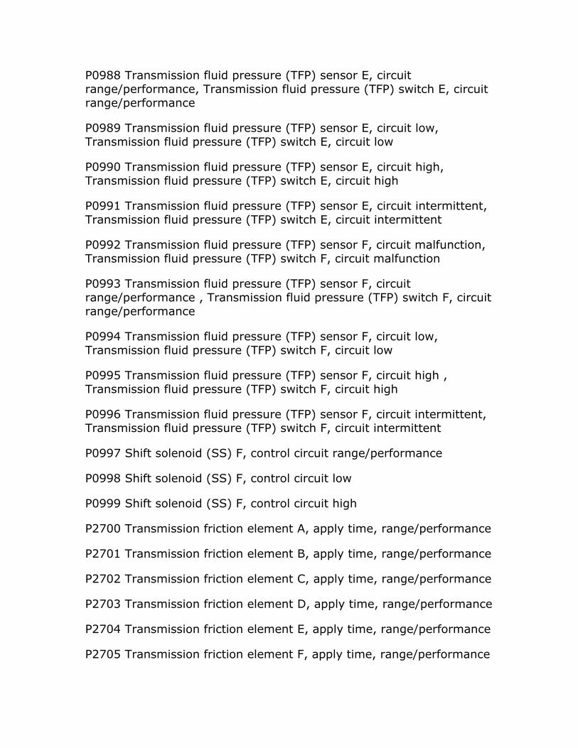
P0988 Transmission fluid pressure (TFP) sensor E, circuit range/performance, Transmission fluid pressure (TFP) switch E, circuit range/performance
P0989 Transmission fluid pressure (TFP) sensor E, circuit low, Transmission fluid pressure (TFP) switch E, circuit low
P0990 Transmission fluid pressure (TFP) sensor E, circuit high, Transmission fluid pressure (TFP) switch E, circuit high
P0991 Transmission fluid pressure (TFP) sensor E, circuit intermittent, Transmission fluid pressure (TFP) switch E, circuit intermittent
P0992 Transmission fluid pressure (TFP) sensor F, circuit malfunction, Transmission fluid pressure (TFP) switch F, circuit malfunction
P0993 Transmission fluid pressure (TFP) sensor F, circuit range/performance , Transmission fluid pressure (TFP) switch F, circuit range/performance
P0994 Transmission fluid pressure (TFP) sensor F, circuit low, Transmission fluid pressure (TFP) switch F, circuit low
P0995 Transmission fluid pressure (TFP) sensor F, circuit high , Transmission fluid pressure (TFP) switch F, circuit high
P0996 Transmission fluid pressure (TFP) sensor F, circuit intermittent, Transmission fluid pressure (TFP) switch F, circuit intermittent
P0997 Shift solenoid (SS) F, control circuit range/performance
P0998 Shift solenoid (SS) F, control circuit low
P0999 Shift solenoid (SS) F, control circuit high
P2700 Transmission friction element A, apply time, range/performance
P2701 Transmission friction element B, apply time, range/performance
P2702 Transmission friction element C, apply time, range/performance
P2703 Transmission friction element D, apply time, range/performance
P2704 Transmission friction element E, apply time, range/performance
P2705 Transmission friction element F, apply time, range/performance

P2706 Shift solenoid (SS) F, circuit malfunction
P2707 Shift solenoid (SS) F, performance problem or solenoid stuck off
P2708 Shift solenoid (SS) F, solenoid stuck on
P2709 Shift solenoid (SS) F, electrical
P2710 Shift solenoid (SS) F, intermittent
P2711 Unexpected mechanical gear disengagement
P2712 Hydraulic power unit leakage
P2713 Transmission fluid pressure (TFP) solenoid D, circuit malfunction
P2714 Transmission fluid pressure (TFP) solenoid D, performance problem or solenoid stuck off
P2715 Transmission fluid pressure (TFP) solenoid D, solenoid stuck on
P2716 Transmission fluid pressure (TFP) solenoid D, electrical
P2717 Transmission fluid pressure (TFP) solenoid D, circuit intermittent
P2718 Transmission fluid pressure (TFP) solenoid D, open circuit
P2719 Transmission fluid pressure (TFP) solenoid D, range/performance
P2720 Transmission fluid pressure (TFP) solenoid D, circuit low
P2721 Transmission fluid pressure (TFP) solenoid D, circuit high
P2722 Transmission fluid pressure (TFP) solenoid E, circuit malfunction
P2723 Transmission fluid pressure (TFP) solenoid E, performance problem or solenoid stuck off
P2724 Transmission fluid pressure (TFP) solenoid E, solenoid stuck on
P2725 Transmission fluid pressure (TFP) solenoid E, electrical
P2726 Transmission fluid pressure (TFP) solenoid E, circuit intermittent
P2727 Transmission fluid pressure (TFP) solenoid F, open circuit
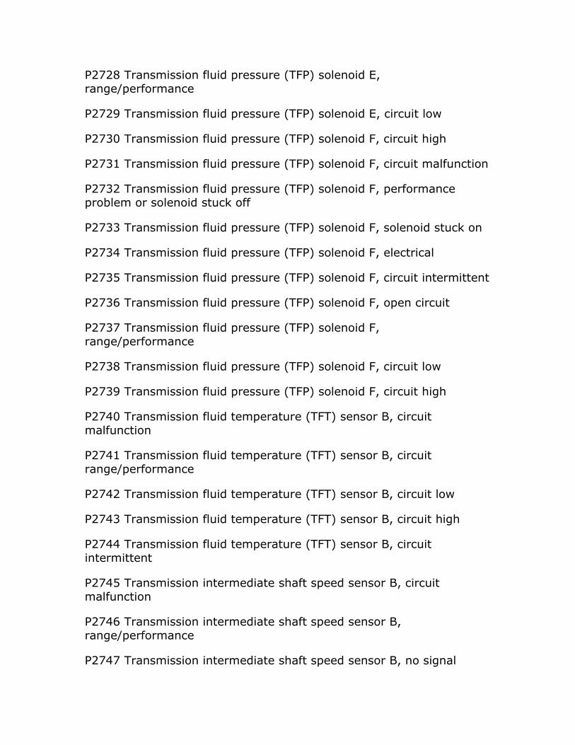
P2728 Transmission fluid pressure (TFP) solenoid E, range/performance
P2729 Transmission fluid pressure (TFP) solenoid E, circuit low
P2730 Transmission fluid pressure (TFP) solenoid F, circuit high
P2731 Transmission fluid pressure (TFP) solenoid F, circuit malfunction
P2732 Transmission fluid pressure (TFP) solenoid F, performance problem or solenoid stuck off
P2733 Transmission fluid pressure (TFP) solenoid F, solenoid stuck on
P2734 Transmission fluid pressure (TFP) solenoid F, electrical
P2735 Transmission fluid pressure (TFP) solenoid F, circuit intermittent
P2736 Transmission fluid pressure (TFP) solenoid F, open circuit
P2737 Transmission fluid pressure (TFP) solenoid F, range/performance
P2738 Transmission fluid pressure (TFP) solenoid F, circuit low
P2739 Transmission fluid pressure (TFP) solenoid F, circuit high
P2740 Transmission fluid temperature (TFT) sensor B, circuit malfunction
P2741 Transmission fluid temperature (TFT) sensor B, circuit range/performance
P2742 Transmission fluid temperature (TFT) sensor B, circuit low
P2743 Transmission fluid temperature (TFT) sensor B, circuit high
P2744 Transmission fluid temperature (TFT) sensor B, circuit intermittent
P2745 Transmission intermediate shaft speed sensor B, circuit malfunction
P2746 Transmission intermediate shaft speed sensor B, range/performance
P2747 Transmission intermediate shaft speed sensor B, no signal

P2748 Transmission intermediate shaft speed sensor B, circuit intermittent
P2749 Transmission intermediate shaft speed sensor C, circuit malfunction
P2750 Transmission intermediate shaft speed sensor C, range/performance
P2751 Transmission intermediate shaft speed sensor C, no signal
P2752 Transmission intermediate shaft speed sensor C, circuit intermittent
P2753 Transmission fluid cooler, open circuit
P2754 Transmission fluid cooler, circuit low
P2755 Transmission fluid cooler, circuit high
P2756 Torque converter clutch (TCC) pressure control solenoid, circuit malfunction
P2757 Torque converter clutch (TCC) pressure control solenoid, performance problem or solenoid stuck off
P2758 Torque converter clutch (TCC) pressure control solenoid, solenoid stuck on
P2759 Torque converter clutch (TCC) pressure control solenoid, electrical fault
P2760 Torque converter clutch (TCC) pressure control solenoid, circuit intermittent
P2761 Torque converter clutch (TCC) pressure control solenoid, open circuit
P2762 Torque converter clutch (TCC) pressure control solenoid, range/performance
P2763 Torque converter clutch (TCC) pressure control solenoid, circuit high
P2764 Torque converter clutch (TCC) pressure control solenoid, circuit low

P2765 Transmission input shaft speed sensor/turbine shaft speed (TSS) sensor B, circuit malfunction
P2766 Transmission input shaft speed sensor/turbine shaft speed (TSS) sensor B, range/performance
P2767 Transmission input shaft speed sensor/turbine shaft speed (TSS) sensor B, no signal
P2768 Transmission input shaft speed sensor/turbine shaft speed (TSS) sensor B, circuit intermittent
P2769 Torque converter clutch (TCC), circuit low
P2770 Torque converter clutch (TCC), circuit high
P2771 Four wheel drive, low gear ratio switch, circuit malfunction
P2772 Four wheel drive, low gear ratio switch, range/performance
P2773 Four wheel drive, low gear ratio switch, circuit low
P2114 Four wheel drive, tow gear ratio switch, circuit high
P2175 Transmission gear selection switch, up shift, range/performance
P2776 Transmission gear selection switch, up shift, circuit low
P2777 Transmission gear selection switch, up shift, circuit high
P2778 Transmission gear selection switch, up shift, circuit intermittent/erratic
P2779 Transmission gear selection switch, downshift, range/performance
P2780 Transmission gear selection switch, downshift, circuit low
P2781 Transmission gear selection switch, downshift, circuit high
P2782 Transmission gear selection switch, downshift, circuit intermittent/erratic
P2783 Torque converter, temperature too high
P2784 Transmission input shaft speed sensor/turbine shaft speed (TSS) sensor A/B, correlation
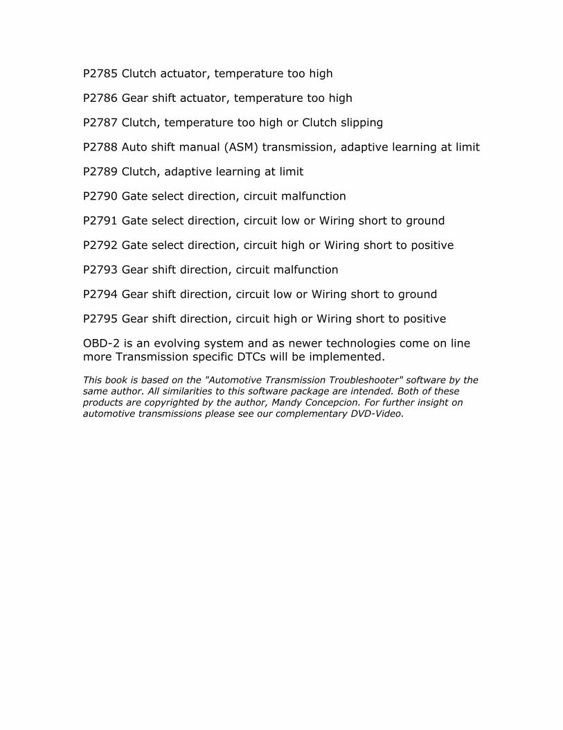
P2785 Clutch actuator, temperature too high
P2786 Gear shift actuator, temperature too high
P2787 Clutch, temperature too high or Clutch slipping
P2788 Auto shift manual (ASM) transmission, adaptive learning at limit
P2789 Clutch, adaptive learning at limit
P2790 Gate select direction, circuit malfunction
P2791 Gate select direction, circuit low or Wiring short to ground
P2792 Gate select direction, circuit high or Wiring short to positive
P2793 Gear shift direction, circuit malfunction
P2794 Gear shift direction, circuit low or Wiring short to ground
P2795 Gear shift direction, circuit high or Wiring short to positive
OBD-2 is an evolving system and as newer technologies come on line more Transmission specific DTCs will be implemented.
This book is based on the "Automotive Transmission Troubleshooter" software by the same author. All similarities to this software package are intended. Both of these products are copyrighted by the author, Mandy Concepcion. For further insight on automotive transmissions please see our complementary DVD-Video.
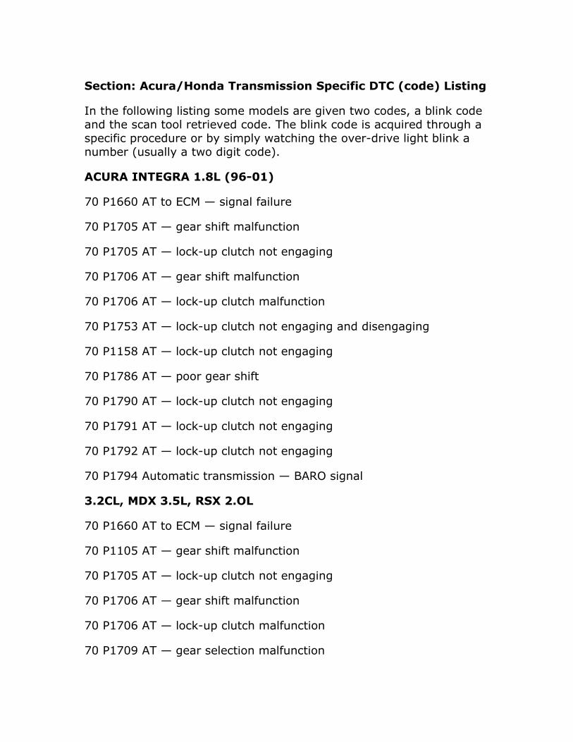
Section: Acura/Honda Transmission Specific DTC (code) Listing
In the following listing some models are given two codes, a blink code and the scan tool retrieved code. The blink code is acquired through a specific procedure or by simply watching the over-drive light blink a number (usually a two digit code).
ACURA INTEGRA 1.8L (96-01)
70 P1660 AT to ECM — signal failure
70 P1705 AT — gear shift malfunction
70 P1705 AT — lock-up clutch not engaging
70 P1706 AT — gear shift malfunction
70 P1706 AT — lock-up clutch malfunction
70 P1753 AT — lock-up clutch not engaging and disengaging
70 P1158 AT — lock-up clutch not engaging
70 P1786 AT — poor gear shift
70 P1790 AT — lock-up clutch not engaging
70 P1791 AT — lock-up clutch not engaging
70 P1792 AT — lock-up clutch not engaging
70 P1794 Automatic transmission — BARO signal
3.2CL, MDX 3.5L, RSX 2.OL
70 P1660 AT to ECM — signal failure
70 P1105 AT — gear shift malfunction
70 P1705 AT — lock-up clutch not engaging
70 P1706 AT — gear shift malfunction
70 P1706 AT — lock-up clutch malfunction
70 P1709 AT — gear selection malfunction
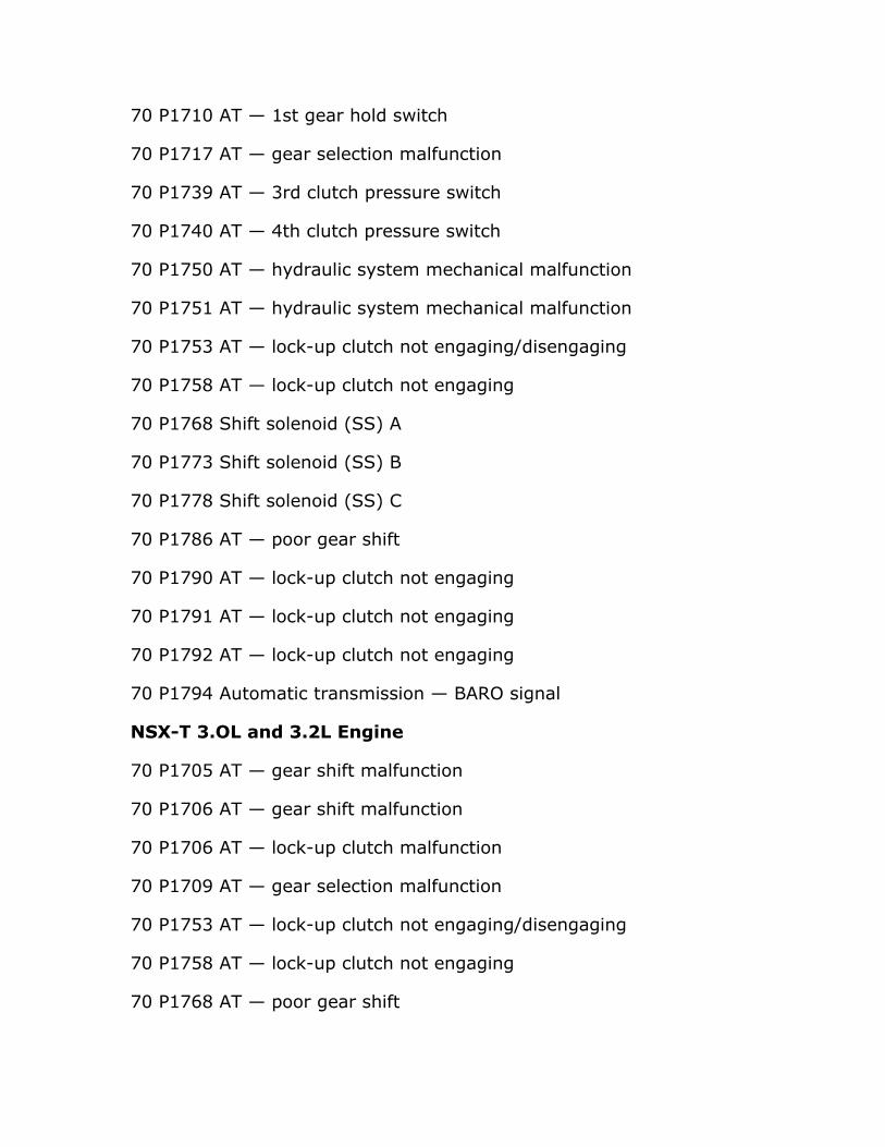
70 P1710 AT — 1st gear hold switch
70 P1717 AT — gear selection malfunction
70 P1739 AT — 3rd clutch pressure switch
70 P1740 AT — 4th clutch pressure switch
70 P1750 AT — hydraulic system mechanical malfunction
70 P1751 AT — hydraulic system mechanical malfunction
70 P1753 AT — lock-up clutch not engaging/disengaging
70 P1758 AT — lock-up clutch not engaging
70 P1768 Shift solenoid (SS) A
70 P1773 Shift solenoid (SS) B
70 P1778 Shift solenoid (SS) C
70 P1786 AT — poor gear shift
70 P1790 AT — lock-up clutch not engaging
70 P1791 AT — lock-up clutch not engaging
70 P1792 AT — lock-up clutch not engaging
70 P1794 Automatic transmission — BARO signal
NSX-T 3.OL and 3.2L Engine
70 P1705 AT — gear shift malfunction
70 P1706 AT — gear shift malfunction
70 P1706 AT — lock-up clutch malfunction
70 P1709 AT — gear selection malfunction
70 P1753 AT — lock-up clutch not engaging/disengaging
70 P1758 AT — lock-up clutch not engaging
70 P1768 AT — poor gear shift
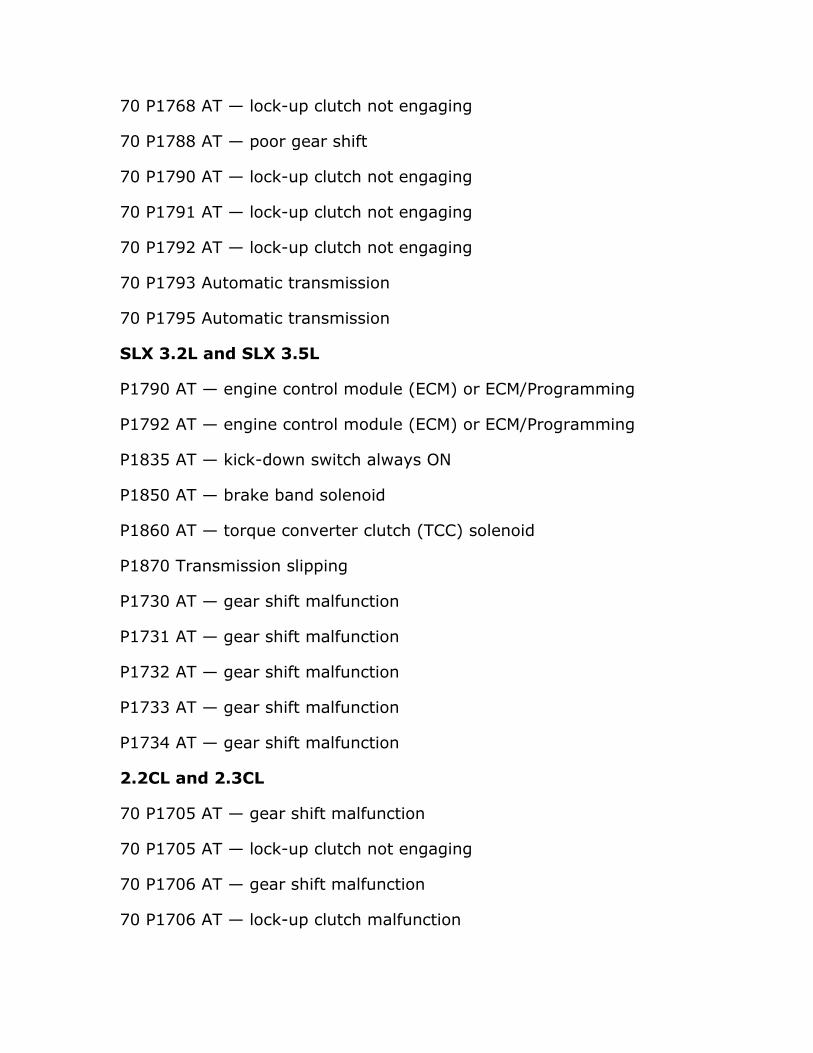
70 P1768 AT — lock-up clutch not engaging
70 P1788 AT — poor gear shift
70 P1790 AT — lock-up clutch not engaging
70 P1791 AT — lock-up clutch not engaging
70 P1792 AT — lock-up clutch not engaging
70 P1793 Automatic transmission
70 P1795 Automatic transmission
SLX 3.2L and SLX 3.5L
P1790 AT — engine control module (ECM) or ECM/Programming
P1792 AT — engine control module (ECM) or ECM/Programming
P1835 AT — kick-down switch always ON
P1850 AT — brake band solenoid
P1860 AT — torque converter clutch (TCC) solenoid
P1870 Transmission slipping
P1730 AT — gear shift malfunction
P1731 AT — gear shift malfunction
P1732 AT — gear shift malfunction
P1733 AT — gear shift malfunction
P1734 AT — gear shift malfunction
2.2CL and 2.3CL
70 P1705 AT — gear shift malfunction
70 P1705 AT — lock-up clutch not engaging
70 P1706 AT — gear shift malfunction
70 P1706 AT — lock-up clutch malfunction

70 P1738 Automatic transmission
70 P1739 Automatic transmission
70 P1753 AT — lock-up clutch not engaging/disengaging
70 P1753 AT — no gear shift
70 P1758 AT — no gear shift
70 P1768 AT — no gear shift
70 P1773 AT — poor gear shift
70 P1773 AT — lock-up clutch not engaging
70 P1791 AT — lock-up clutch not engaging
2.5TL
70 P1660 AT to 1CM — data line failure
70 P1705 AT — gear shift malfunction
70 P1705 AT — lock-up clutch not engaging
70 P1706 AT — gear shift malfunction
10 P1706 AT — lock-up clutch malfunction
70 P1753 AT — lock-up clutch not engaging/disengaging
70 P1758 AT — no gear shift
70 P1768 AT — no gear shift
70 P1768 AT — lock-up clutch not engaging
70 P1786 AT — poor gear shift
70 P1787 AT — lock-up clutch malfunction
70 P1790 AT — lock-up clutch not engaging
70 P1791 AT — lock-up clutch not engaging
70 P1192 AT — lock-up clutch not engaging
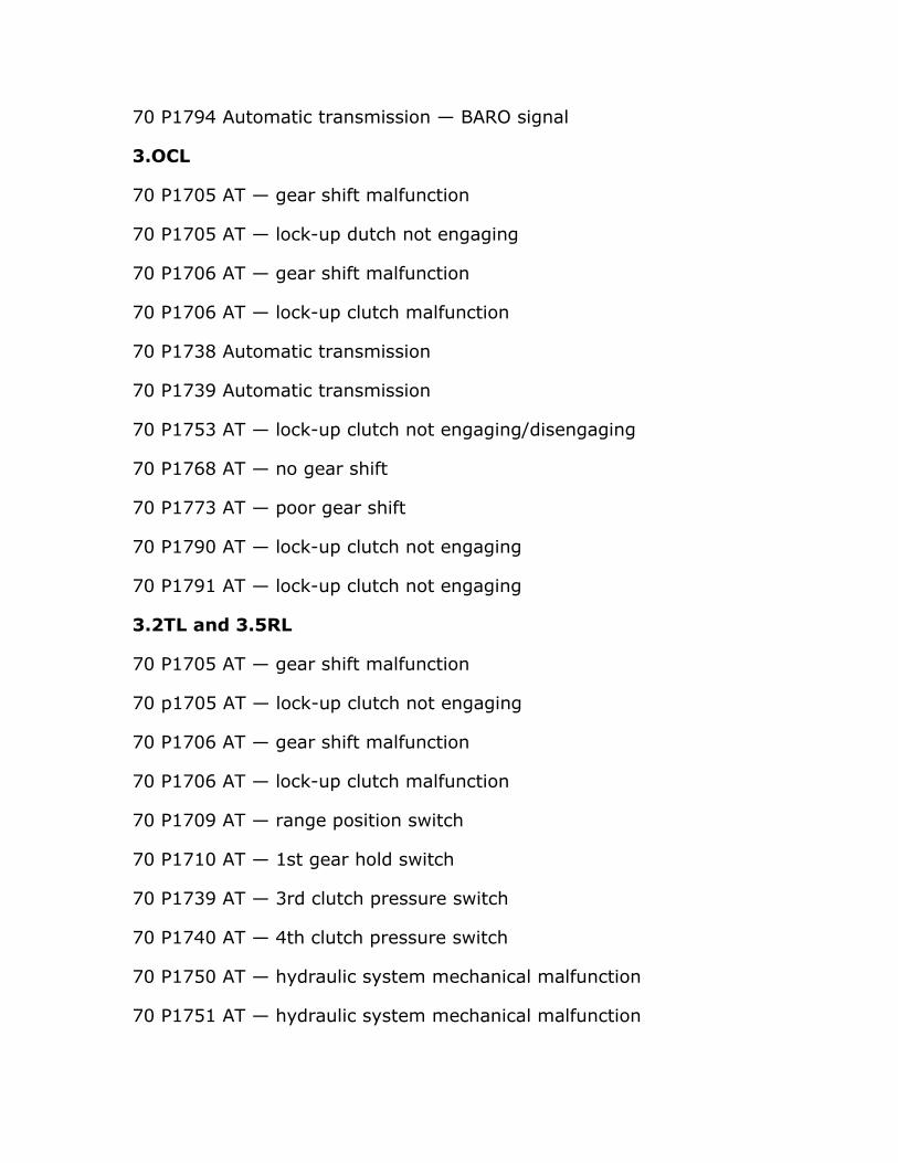
70 P1794 Automatic transmission — BARO signal
3.OCL
70 P1705 AT — gear shift malfunction
70 P1705 AT — lock-up dutch not engaging
70 P1706 AT — gear shift malfunction
70 P1706 AT — lock-up clutch malfunction
70 P1738 Automatic transmission
70 P1739 Automatic transmission
70 P1753 AT — lock-up clutch not engaging/disengaging
70 P1768 AT — no gear shift
70 P1773 AT — poor gear shift
70 P1790 AT — lock-up clutch not engaging
70 P1791 AT — lock-up clutch not engaging
3.2TL and 3.5RL
70 P1705 AT — gear shift malfunction
70 p1705 AT — lock-up clutch not engaging
70 P1706 AT — gear shift malfunction
70 P1706 AT — lock-up clutch malfunction
70 P1709 AT — range position switch
70 P1710 AT — 1st gear hold switch
70 P1739 AT — 3rd clutch pressure switch
70 P1740 AT — 4th clutch pressure switch
70 P1750 AT — hydraulic system mechanical malfunction
70 P1751 AT — hydraulic system mechanical malfunction
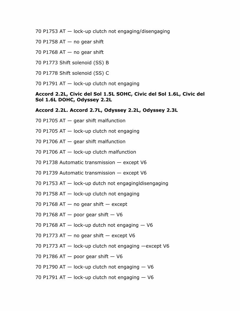
70 P1753 AT — lock-up clutch not engaging/disengaging
70 P1758 AT — no gear shift
70 P1768 AT — no gear shift
70 P1773 Shift solenoid (SS) B
70 P1778 Shift solenoid (SS) C
70 P1791 AT — lock-up clutch not engaging
Accord 2.2L, Civic del Sol 1.5L SOHC, Civic del Sol 1.6L, Civic del Sol 1.6L DOHC, Odyssey 2.2L
Accord 2.2L. Accord 2.7L, Odyssey 2.2L, Odyssey 2.3L
70 P1705 AT — gear shift malfunction
70 P1705 AT — lock-up clutch not engaging
70 P1706 AT — gear shift malfunction
70 P1706 AT — lock-up clutch malfunction
70 P1738 Automatic transmission — except V6
70 P1739 Automatic transmission — except V6
70 P1753 AT — lock-up dutch not engagingldisengaging
70 P1758 AT — lock-up clutch not engaging
70 P1768 AT — no gear shift — except
70 P1768 AT — poor gear shift — V6
70 P1768 AT — lock-up dutch not engaging — V6
70 P1773 AT — no gear shift — except V6
70 P1773 AT — lock-up clutch not engaging —except V6
70 P1786 AT — poor gear shift — V6
70 P1790 AT — lock-up clutch not engaging — V6
70 P1791 AT — lock-up clutch not engaging — V6

70 P1792 AT — lock-up clutch not engaging — V6
70 P1794 Automatic transmission — BARO signal
Accord 2.3L, Accord 2.4L, Accord 3.OL, civic l.7L, Civic 2.OL, CR-v 2.4L, Odyssey 3.5L, S2000 2.OL
70 P1705 AT — gear shift malfunction
70 P1705 CVT — gear shift malfunction
70 P1706 Automatic transmission
70 P1706 CVT — gear shift malfunction
70 P1717 AT — gear selection malfunction
70 P1730 AT — gear shift malfunction
70 P1731 AT — gear shift malfunction
70 AT — gear shift malfunction
Accord 2.3L Accord 2.4L, Accord 3.OL, Civic IlL, Civic 2.OL, CR-V 2.41, Odyssey 3.51, S2000 2.01, S2000 2.2L
70 P1733 AT — gear shift malfunction
70 P1734 AT — gear shift malfunction
70 P1738 Automatic transmission
70 P1739 Automatic transmission
70 P1740 AT — 4th clutch pressure switch
70 P1750 AT — hydraulic system mechanical malfunction
70 P1751 AT — hydraulic system mechanical malfunction
70 P1753 AT — lock-up clutch not engaging/disengaging
70 P1753 AT — no gear shift
70 P1768 AT — no gear shift
70 P1768 AT — lock-up clutch not engaging
70 P1773 AT — no gear shift
70 P1773 AT — lock-up clutch not engaging
70 P1790 AT — lock-up clutch not engaging
70 P1792 AT — lock-up clutch not engaging
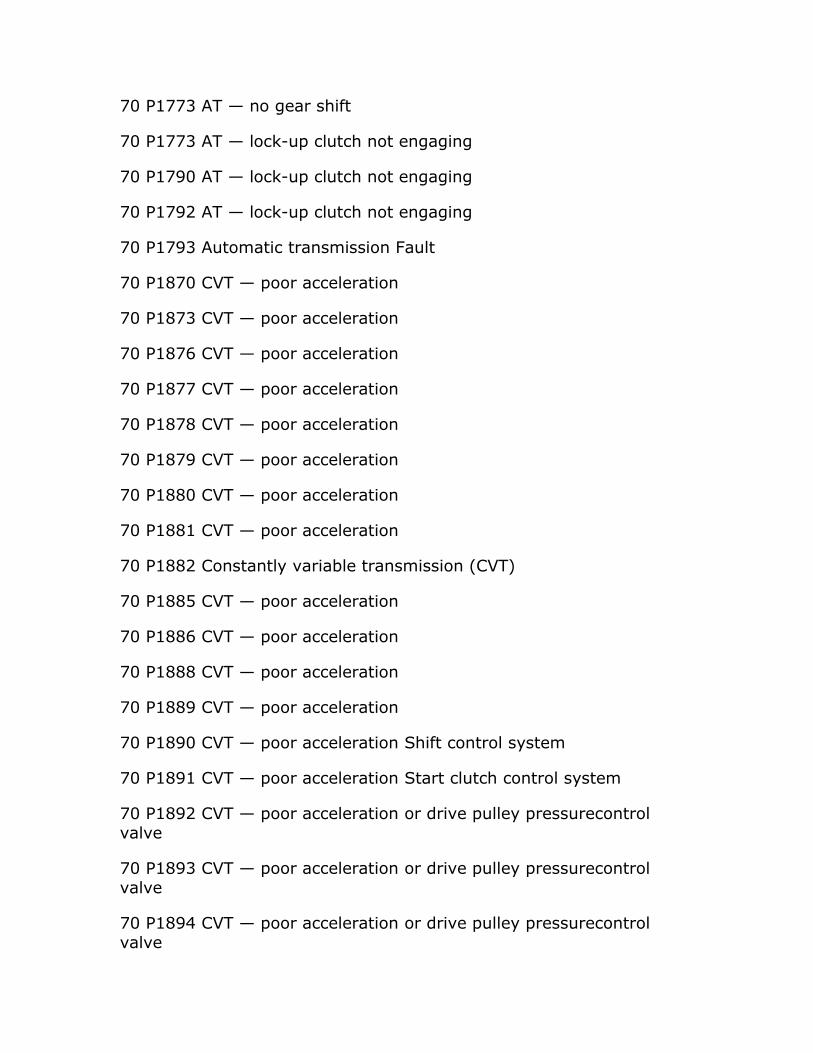
70 P1793 Automatic transmission Fault
70 P1870 CVT — poor acceleration
70 P1873 CVT — poor acceleration
70 P1876 CVT — poor acceleration
70 P1877 CVT — poor acceleration
70 P1878 CVT — poor acceleration
70 P1879 CVT — poor acceleration
70 P1880 CVT — poor acceleration
70 P1881 CVT — poor acceleration
70 P1882 Constantly variable transmission (CVT)
70 P1885 CVT — poor acceleration
70 P1886 CVT — poor acceleration
70 P1888 CVT — poor acceleration
70 P1889 CVT — poor acceleration
70 P1890 CVT — poor acceleration Shift control system
70 P1891 CVT — poor acceleration Start clutch control system
70 P1892 CVT — poor acceleration or drive pulley pressurecontrol valve
70 P1893 CVT — poor acceleration or drive pulley pressurecontrol valve
70 P1894 CVT — poor acceleration or drive pulley pressurecontrol valve
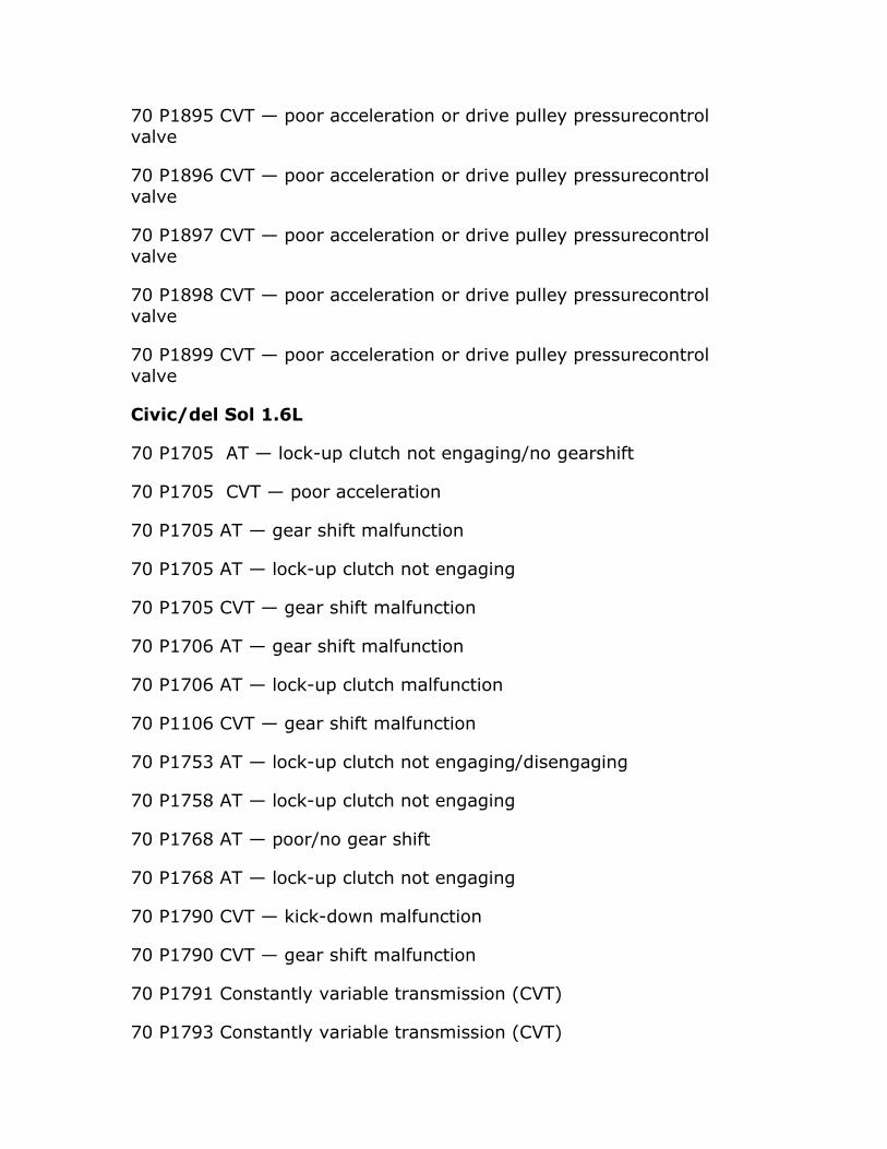
70 P1895 CVT — poor acceleration or drive pulley pressurecontrol valve
70 P1896 CVT — poor acceleration or drive pulley pressurecontrol valve
70 P1897 CVT — poor acceleration or drive pulley pressurecontrol valve
70 P1898 CVT — poor acceleration or drive pulley pressurecontrol valve
70 P1899 CVT — poor acceleration or drive pulley pressurecontrol valve
Civic/del Sol 1.6L
70 P1705 AT — lock-up clutch not engaging/no gearshift
70 P1705 CVT — poor acceleration
70 P1705 AT — gear shift malfunction
70 P1705 AT — lock-up clutch not engaging
70 P1705 CVT — gear shift malfunction
70 P1706 AT — gear shift malfunction
70 P1706 AT — lock-up clutch malfunction
70 P1106 CVT — gear shift malfunction
70 P1753 AT — lock-up clutch not engaging/disengaging
70 P1758 AT — lock-up clutch not engaging
70 P1768 AT — poor/no gear shift
70 P1768 AT — lock-up clutch not engaging
70 P1790 CVT — kick-down malfunction
70 P1790 CVT — gear shift malfunction
70 P1791 Constantly variable transmission (CVT)
70 P1793 Constantly variable transmission (CVT)

70 P1870 CVT — poor acceleration
70 P1873 CVT — poor acceleration
70 P1879 CVT — poor acceleration
70 P1882 Constantly variable transmission (CVT)
70 P1885 CVT — poor acceleration
70 P1886 CVT — poor acceleration
70 P1888 CVT — poor acceleration
70 P1890/P1891 CVT — poor acceleration
CR-V
70 P1705 AT — gear shift malfunction
70 P1705 AT — lock-up clutch not engaging
70 P1706 AT — gear shift malfunction
70 P1706 AT — lock-up clutch malfunction
70 P1753 AT — lock-up clutch not engaging/disengaging
70 P1758 AT — lock-up clutch not engaging
70 P1768 AT — poor gear shift
70 P1768 AT — lock-up clutch not engaging
Element 2.4L
P1731 AT — gear shift malfunction
P1732 AT — gear shift malfunction
P1735 AT — gear shift malfunction
P1736 AT — gear shift malfunction
Passport 2.6L, 3.2L (Isuzu)
P1790 Engine control module (ECM) — AT ROM checksum error
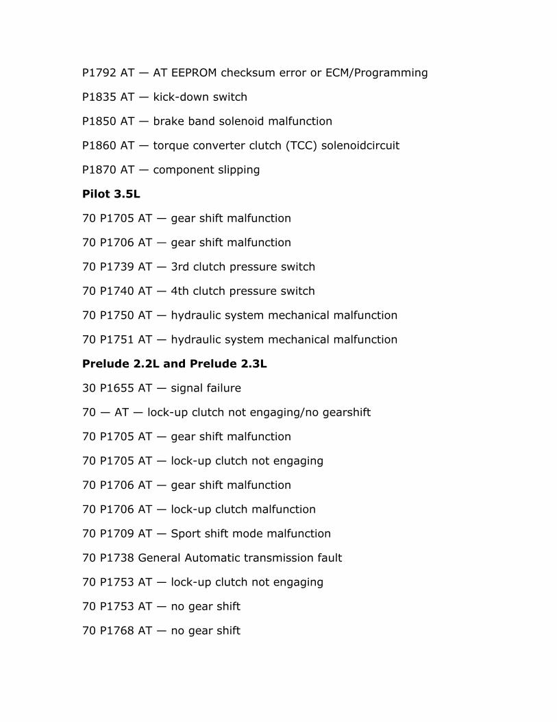
P1792 AT — AT EEPROM checksum error or ECM/Programming
P1835 AT — kick-down switch
P1850 AT — brake band solenoid malfunction
P1860 AT — torque converter clutch (TCC) solenoidcircuit
P1870 AT — component slipping
Pilot 3.5L
70 P1705 AT — gear shift malfunction
70 P1706 AT — gear shift malfunction
70 P1739 AT — 3rd clutch pressure switch
70 P1740 AT — 4th clutch pressure switch
70 P1750 AT — hydraulic system mechanical malfunction
70 P1751 AT — hydraulic system mechanical malfunction
Prelude 2.2L and Prelude 2.3L
30 P1655 AT — signal failure
70 — AT — lock-up clutch not engaging/no gearshift
70 P1705 AT — gear shift malfunction
70 P1705 AT — lock-up clutch not engaging
70 P1706 AT — gear shift malfunction
70 P1706 AT — lock-up clutch malfunction
70 P1709 AT — Sport shift mode malfunction
70 P1738 General Automatic transmission fault
70 P1753 AT — lock-up clutch not engaging
70 P1753 AT — no gear shift
70 P1768 AT — no gear shift

70 P1773 AT — no gear shift
70 P1790 AT — lock-up clutch not engaging
70 P1791 AT — lock-up clutch not engaging
This book is based on the "Automotive Transmission Troubleshooter" software by the same author. All similarities to this software package are intended. Both of these products are copyrighted by the author, Mandy Concepcion. For further insight on automotive transmissions please see our complementary DVD-Video.

Section: Acura/Honda Transmission Application
M5HA/M5DA - (1995-2005) 3.2TL, 3.5RL
M7WA/MGFA/ - (2000-06) 3.2TL, CL
MGHA - (2000-02) MDX-SUV
MDKA/BDKA - (2003-up) MDX-SUV
BAXA - (97-2002) Accord, Odyssey
MP1A - (1991-02) Prelude, Civic
M6HA - (1997-2004) Prelude, Civic
BMXA/SLXA - (2000-05) Civic
B7TA/B7YA - (1999-2000) Odyssey, Accord V-6
BYBA/BVGA - (2000-04) Odyssey, Pilot, Ridgeline
BGRA - (2005-up) Odyssey, Pilot, Ridgeline
BZKA/MZKA - (2003-up) Element
MCVA/MRVA - (2001-2004) CRV
MKYA/GPLA/MKZA/GPPA - (2004-up) CRV
4L30-E - (1996-2002) Honda-Passport, SLX
This book is based on the "Automotive Transmission Troubleshooter" software by the same author. All similarities to this software package are intended. Both of these products are copyrighted by the author, Mandy Concepcion. For further insight on automotive transmissions please see our complementary DVD-Video.
Section: Acura/Honda Transmissions Component Operation
IMPORTANT FACTS ABOUT ACURA AND HONDA TRANSMISSIONS
All HONDA/ACURA transmissions have a natural gear position. This is the normal hydraulic fluid path when the transmission solenoids are all OFF or without power. This is also the Limp-in Mode gear or the shift gear that the vehicle stays in whenever there's a major fault present. This fact automatically tells you that in the event that the trans is stuck in limp-in mode, usually 2nd or 3rd gear, then most likely culprit is a blown main feed fuse. Then you have to find out what caused the fuse to burn originally. A clue to this type of fault in when the TCM or PCM has issued a faulty code for all solenoids. This usually points to the main fuse and a possible short circuit that caused the fuse to go out.
So always remember that all transmissions have a natural gear when all power is off or the main connector is disconnected. There are other reasons why the transmission TCM is stuck in limp-in mode. This could also be due to a faulty TPS, open solenoid, faulty TCM, or any other electrical fault. On newer systems, the TCM is also using the WSS or wheel speed sensor to decide when to shift the transmission.
GENERAL OPERATION and DESCRIPTION
Honda's automatic transmissions are unusual in that they do not use planetary gears like nearly all other makers. Instead, the Hondamatic and its successors use traditional sliding gears in parallel like a manual transmission. Honda was forced to invent their new system due to the vast array of patents on automatic transmission technology held by Borg-Warner and others.
Honda initially chose to integrate the transmission and engine block for its first application (in the N360) as in the Mini. The Hondamatic incorporated a lockup function, which Honda called a third ratio, and had manual gear selection. The company's early transmissions also used a patented torque converter which used stator force rather than hydraulic controls for shifting.
The company's naming scheme is also confusing, as it is specific to a single model of vehicle and some identifiers are reused.
DESCRIPTION
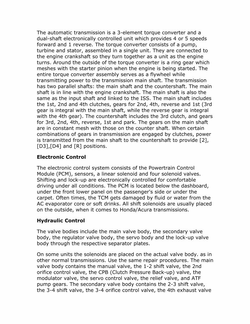
The automatic transmission is a 3-element torque converter and a dual-shaft electronically controlled unit which provides 4 or 5 speeds forward and 1 reverse. The torque converter consists of a pump, turbine and stator, assembled in a single unit. They are connected to the engine crankshaft so they turn together as a unit as the engine turns. Around the outside of the torque converter is a ring gear which meshes with the starter pinion when the engine is being started. The entire torque converter assembly serves as a flywheel while transmitting power to the transmission main shaft. The transmission has two parallel shafts: the main shaft and the countershaft. The main shaft is in line with the engine crankshaft. The main shaft is also the same as the input shaft and linked to the ISS. The main shaft includes the 1st, 2nd and 4th clutches, gears for 2nd, 4th, reverse and 1st (3rd gear is integral with the main shaft, while the reverse gear is integral with the 4th gear). The countershaft includes the 3rd clutch, and gears for 3rd, 2nd, 4th, reverse, 1st and park. The gears on the main shaft are in constant mesh with those on the counter shaft. When certain combinations of gears in transmission are engaged by clutches, power is transmitted from the main shaft to the countershaft to provide [2],[D3],[D4] and [R] positions.
Electronic Control
The electronic control system consists of the Powertrain Control Module (PCM), sensors, a linear solenoid and four solenoid valves. Shifting and lock-up are electronically controlled for comfortable driving under all conditions. The PCM is located below the dashboard, under the front lower panel on the passenger's side or under the carpet. Often times, the TCM gets damaged by fluid or water from the AC evaporator core or soft drinks. All shift solenoids are usually placed on the outside, when it comes to Honda/Acura transmissions.
Hydraulic Control
The valve bodies include the main valve body, the secondary valve body, the regulator valve body, the servo body and the lock-up valve body through the respective separator plates.
On some units the solenoids are placed on the actual valve body. as in other normal transmissions. Use the same repair procedures. The main valve body contains the manual valve, the 1-2 shift valve, the 2nd orifice control valve, the CPB (Clutch Pressure Back-up) valve, the modulator valve, the servo control valve, the relief valve, and ATF pump gears. The secondary valve body contains the 2-3 shift valve, the 3-4 shift valve, the 3-4 orifice control valve, the 4th exhaust valve

and the Clutch Pressure Control (CPC) valve. The regulator valve body contains the pressure regulator valve, the torque converter check valve, the cooler relief valve, and the lock-up control valve. The servo body contains the servo valve which is integrated with the reverse shift fork, and the accumulators. The lock-up valve body contains the lock-up shift valve and the lock-up timing valve. The linear solenoid and the shift control solenoid valve A/B are bolted on the outside of the transmission housing, and the lock-up control solenoid valve A/B is bolted on the outside of the torque converter housing. Fluid from regulator passes through the manual valve to the various control valves. The clutches receive fluid from their respective feed pipes or internal hydraulic circuit.
Shift Control Mechanism
Input from various sensors located throughout the car determines which shift control solenoid valve the Powertrain Control Module (PCM) will activate. Activating a shift control solenoid valve changes modulator pressure, causing a shift valve to move. This pressurizes a line to one of the clutches, engaging that clutch and its corresponding gear. The shift control solenoid valves A and B are controlled by the PCM.
Lock-up Mechanism
In [D4] position, in 3rd and 4th, and in [D3] position in 3rd, pressurized fluid is drained from the back of the torque converter through a fluid passage, causing the lock-up piston to be held against the torque converter cover. As this takes place, the mainshaft rotates at the same as the engine crankshaft. Together with hydraulic control, the PCM optimizes the timing of the lock-up mechanism. The lock-up valves control the range of lock-up according to lock-up control solenoid valves A and B, and linear solenoid. When lock-up control solenoid valves A and B activate, the modulator pressure changes. The lockup control solenoid valves A and B and the linear solenoid are controlled by the Powertrain Control Module (PCM) .
DESCRIPTION AND OPERATION
The electronic control system consists of a Powertrain Control Module (PCM), sensors, a linear solenoid and four solenoid valves. Shifting and lock-up are electronically controlled for comfortable driving under all conditions. The PCM is located below the dashboard, under the front lower panel on the passenger's side.
Shift Control
The PCM instantaneously determines which gear should be selected by various signals sent from sensors, and actuates the shift control solenoid valves A and B to control shifting. Also, a Grade Logic Control System has been adopted to control shifting in D4 position while the vehicle is ascending or descending a slope, or reducing speed.
Lock-up Control
From sensor input signals, the PCM determines whether to turn the lock-up ON or OFF, and activates lock-up control solenoid valve A and/or B accordingly. The combination of driving signals to lock-up control solenoid valves A and B and the linear solenoid pressure is shown in the table below.
GRADE LOGIC CONTROL SYSTEM
The PCM compares actual driving conditions with driving conditions memorized in the PCM, based on the input from the vehicle speed sensor, the throttle position sensor, the barometric pressure sensor, the engine coolant temperature sensor, the brake switch signal and the shift lever position signal, to control shifting while a vehicle is ascending or descending a slope, or reducing speed. Ascending Control:
When the PCM determines that the vehicle is climbing a hill in position, the system extends the engagement area of 2nd gear and 3rd gear to prevent the transmission from frequently shifting between 2nd and 3rd gears, and between 3rd and 4th gears, so the vehicle can run smooth and have more power when needed. There are two ascending modes with different 3rd gear driving areas according to the magnitude of a gradient stored in the PCM.
The PCM memory contains shift schedules between 2nd and 3rd gears, and between 3rd and 4th gears that enable the PCM's fuzzy logic to automatically select the most suitable gear according to the magnitude of a gradient.
Fuzzy logic is a form of artificial intelligence that lets computers respond to changing conditions much like a human mind would.
When the PCM determines that the vehicle is going down a hill in position, the shift-up speed from 3rd to 4th gear when the throttle is closed becomes faster than the set speed for flat road driving to widen
the 3rd gear driving area. This, in combination with engine braking from the deceleration lock-up, achieves smooth driving when the vehicle is descending. There are two descending modes with different downshift (4 - 3) schedules according to the magnitude of a gradient stored in the PCM. When the vehicle is in 4th gear, and you are decelerating on a gradual hill, or when you are applying the brakes on a steep hill, the transmission will downshift to 3rd gear. When you accelerate, the transmission will then return to 4th gear.
When the vehicle goes around a corner, and needs to first decelerate and then accelerate, the PCM sets the data for deceleration control to reduce the number of times the transmission shifts. When the vehicle is decelerating from speeds above 26 mph (41 km/h), the PCM shifts the transmission from 4th to 2nd earlier than normal to cope with upcoming acceleration.
This book is based on the "Automotive Transmission Troubleshooter" software by the same author. All similarities to this software package are intended. Both of these products are copyrighted by the author, Mandy Concepcion. For further insight on automotive transmissions please see our complementary DVD-Video.

Section: Acura/Honda Transmission Oil Pan (ID) Identification
Honda/Acura transmissions don't have a transmission oil pan. They mostly carry the shift solenoids on the outside of the transmission. For this reason an oil pan is not needed. To get to the valve body the transmission has to be opened or halved completely. To help you identify the transmission here you can reference the different diagrams that have been extracted from actual photographs from the author's photo library.
4L30E
B7TA/B7YA
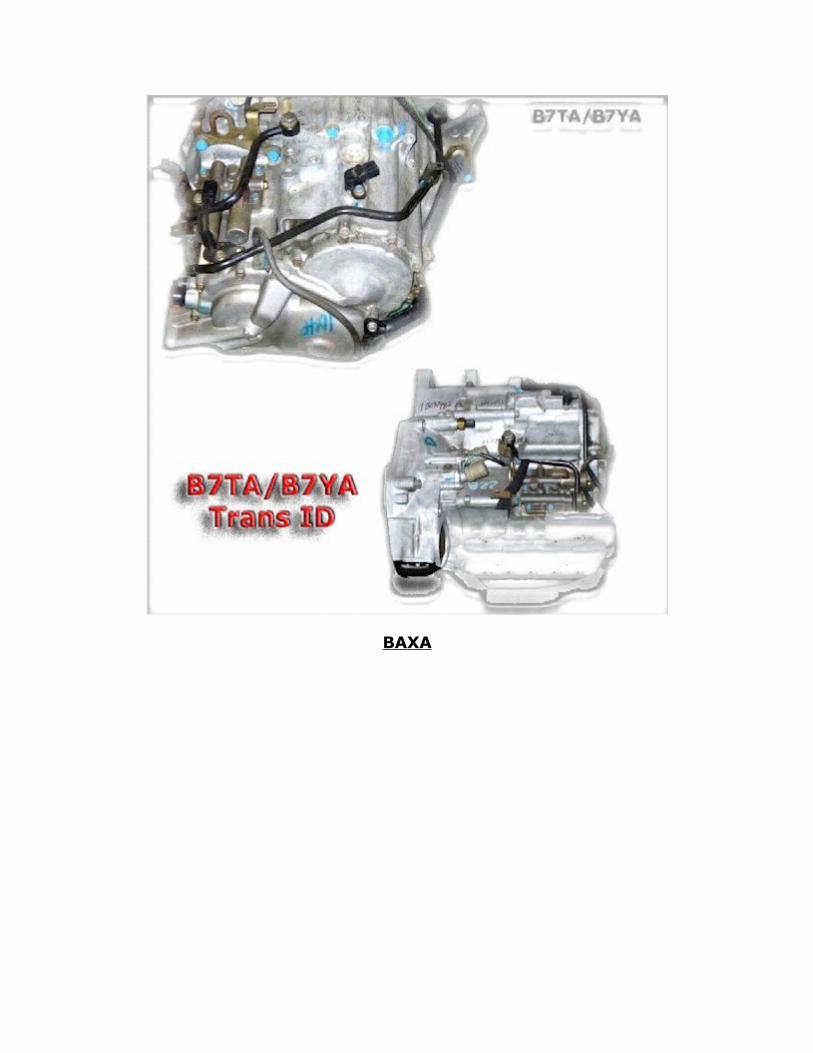
BAXA

BGRA
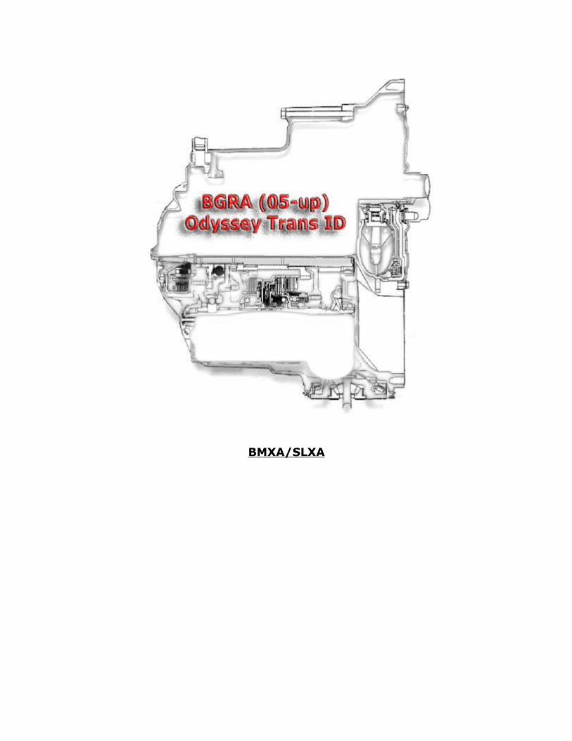
BMXA/SLXA
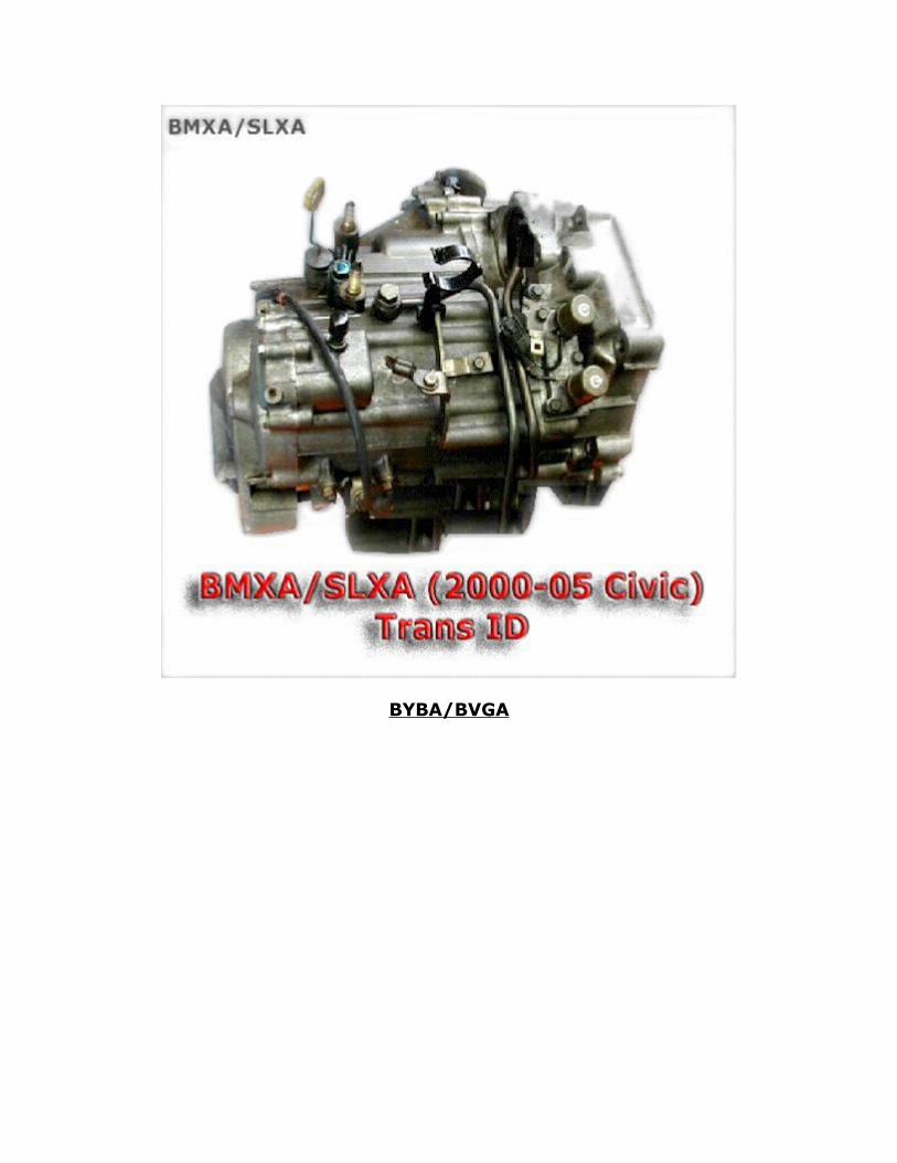
BYBA/BVGA
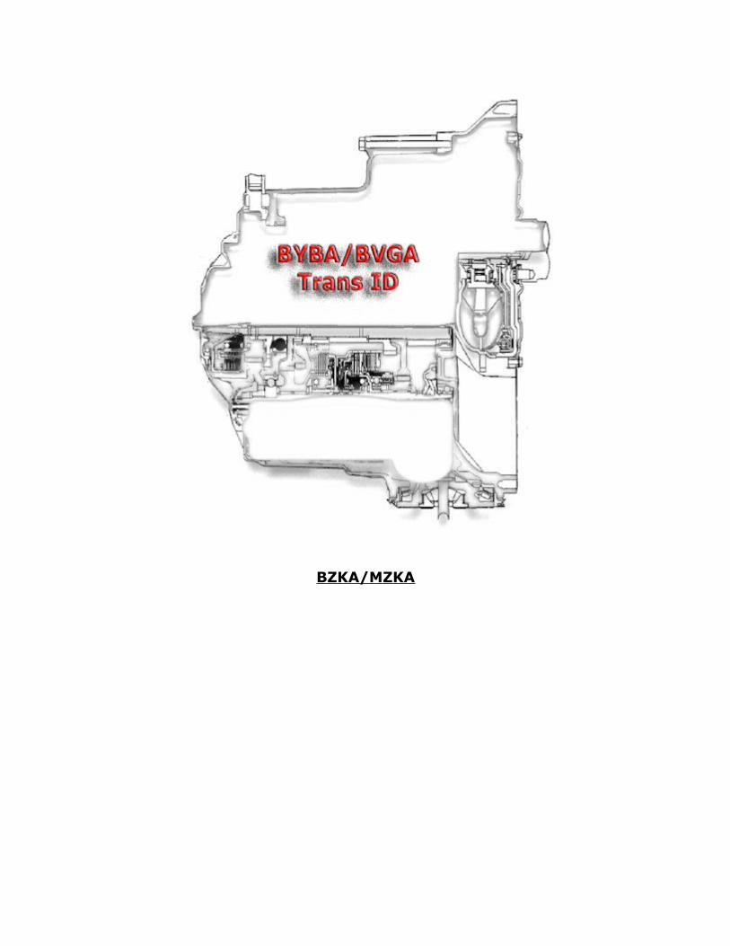
BZKA/MZKA

M5HA/M5DA
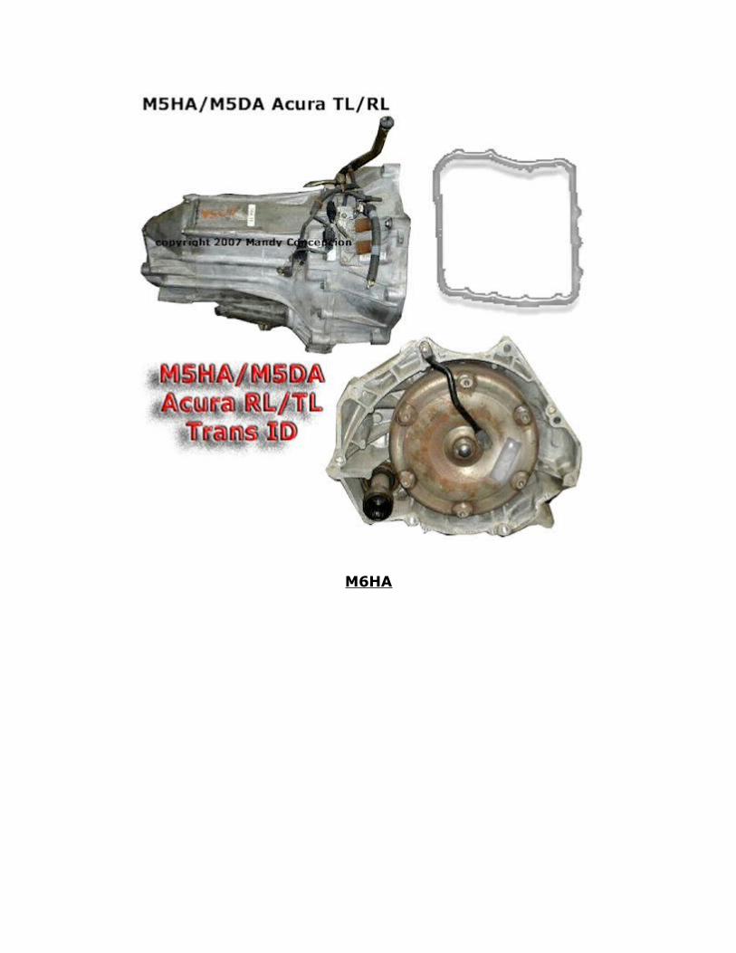
M6HA

M7WA/MGFA
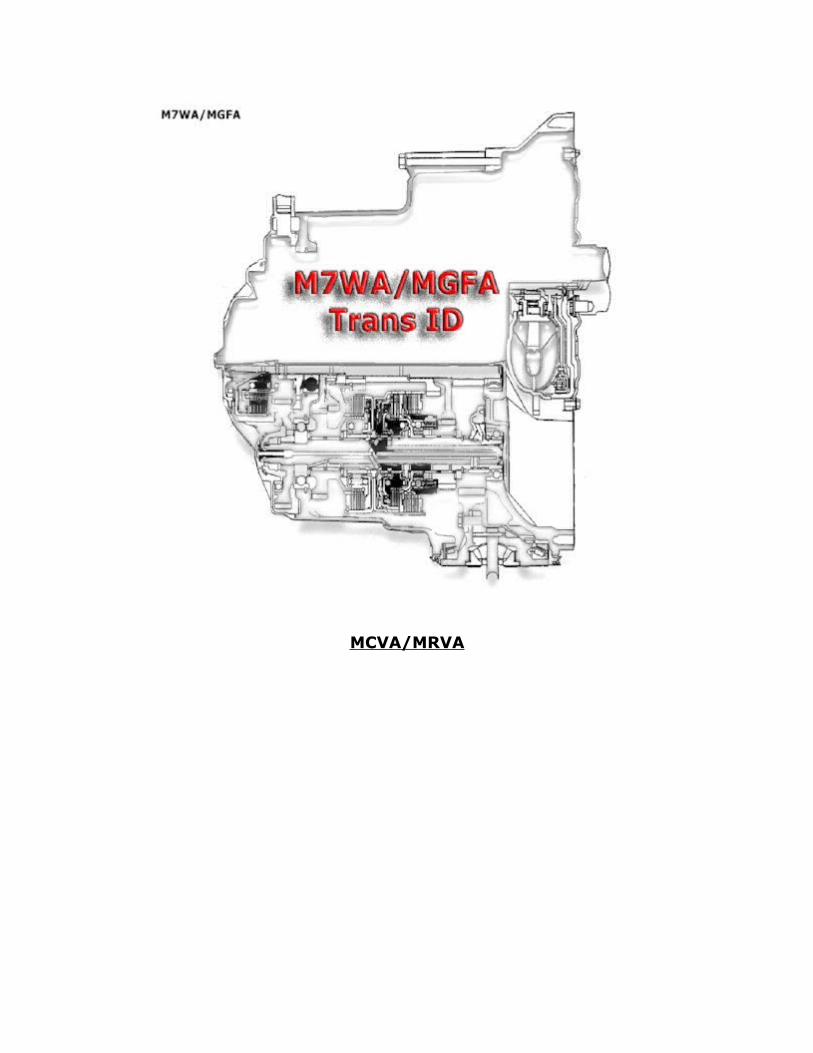
MCVA/MRVA

MDKA/BDKA
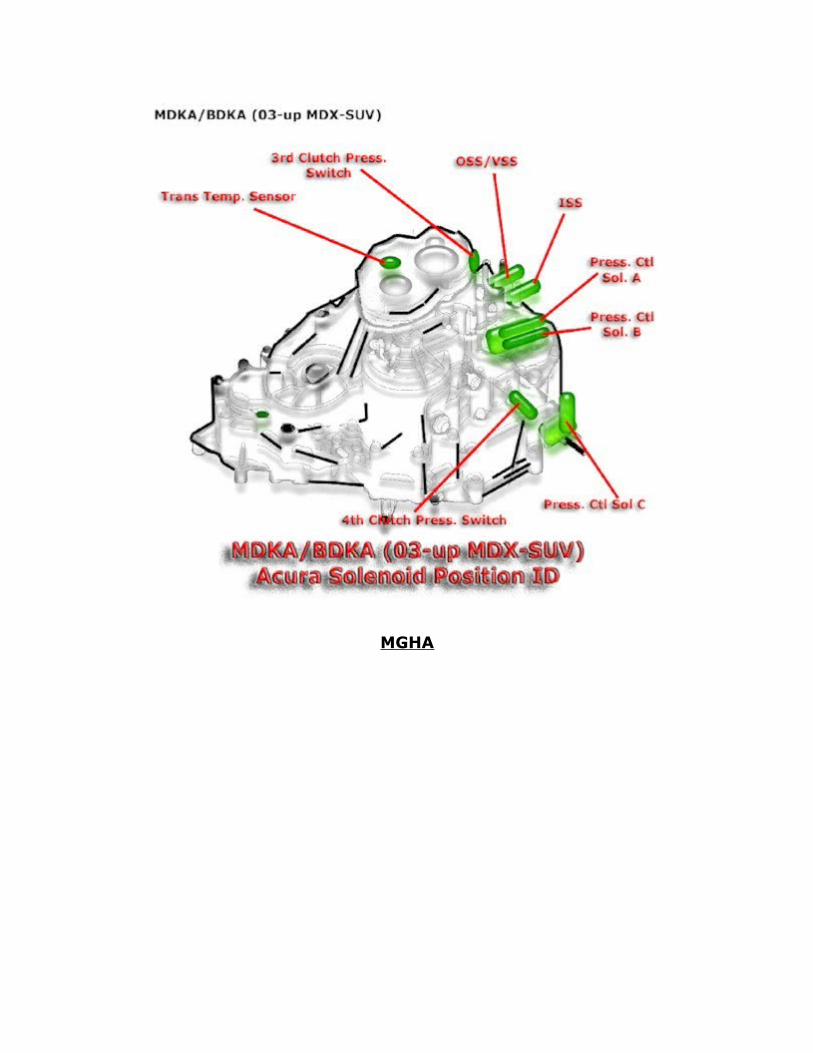
MGHA
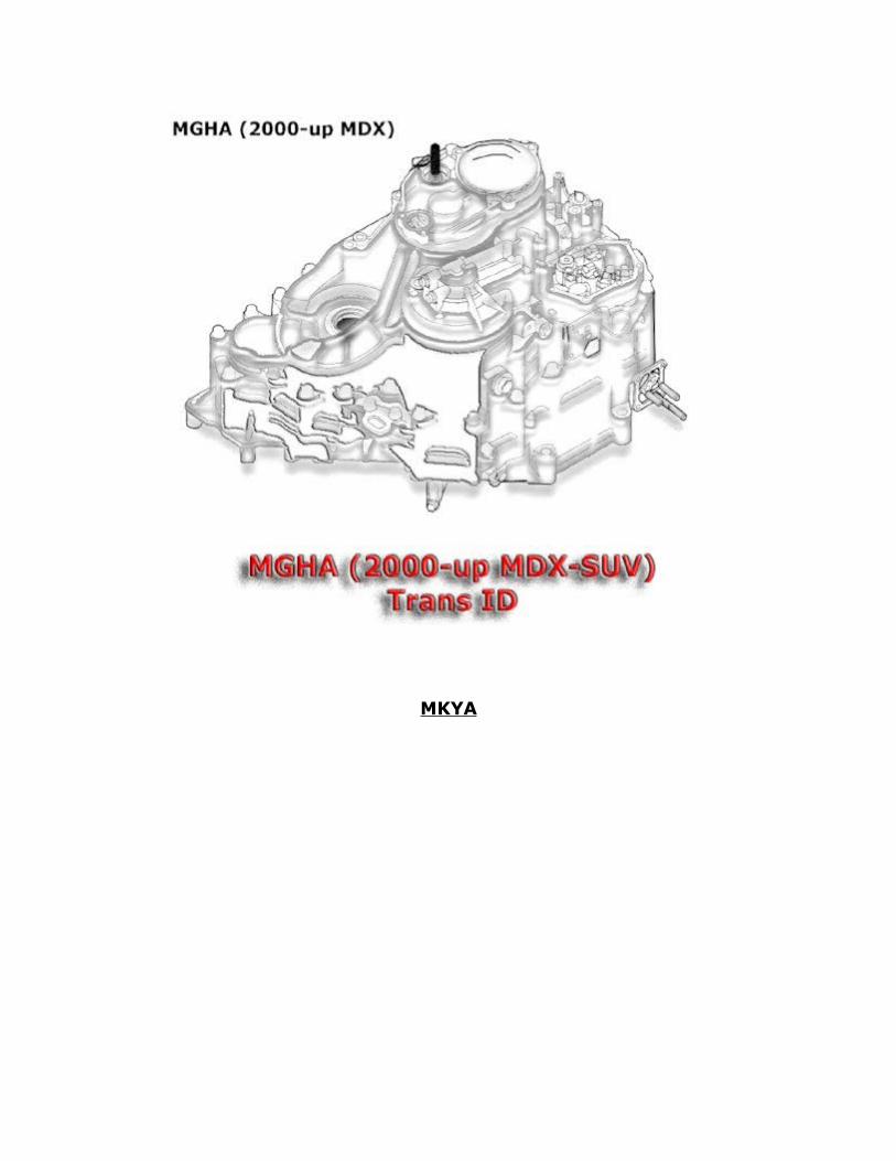
MKYA

MP1A

This book is based on the "Automotive Transmission Troubleshooter" software by the same author. All similarities to this software package are intended. Both of these products are copyrighted by the author, Mandy Concepcion. For further insight on automotive transmissions please see our complementary DVD-Video.

Section: Acura/Honda Shift Solenoids and Electrical Component Testing (Shift Solenoids, TCC Solenoid, Pressure Control Solenoid (EPC), TPS, TCM Test, Pressure Switches)
4L30E
Shift Solenoids
The Honda 4L30-E 1-2/3-4 shift solenoids are normally closed. The 2-3 solenoid is normally open. 2-3 Solenoid is ground controlled through pin A at trans connector. 1-2/3-4 solenoids are GROUND controlled through pin C at the trans connector. The solenoids are fed POWER at pin D. Solenoid resistance should be between 16 and 22 Ohms. Meassure voltage between pins A or B and Ground. You should see 12 volts when solenoid is not actuated and almost 0.00 volts when the TCM actuates the solenoid. If no voltage is seen at pulsed side, then solenoid coil is open or wire is broken.
SHIFT-SOLENOID Resistance = 16 - 22 Ohms
MAXIMUM CURRENT at room temperature = 0.75 Amps or 750mA
POWER FEED Test between Batt + and Solenoid Power-Feed = 100 to 300 mVolts w/KOER
TCC On/Off solenoid
The Honda 4L30-E TCC On/Off solenoid is used to control the application of the torque converter wet clutches. This is just an Allow or Not-allow device. Once the TCC On/Off solenoids allows fluid passage, the TCC PWM solenoid then controls the engagement and makes actuation harsher or softer. The TCC On/Off solenoid is very similar electrically and often the same as the normal shift solenoids. Ignition power feed is supplied to the solenoid by the TCM at pin D. The TCM/PCM uses ground to actuate the TCC sol through pins A.
TCC On/Off Resistance = 16 - 22 Ohms
MAXIMUM CURRENT at room temperature = 0.75 Amps or 750 mA
POWER FEED Test between Batt + and Solenoid Power-Feed = 100 to 300 mVolts w/KOER
TCC On/Off Solenoid
The Honda 4L30-E uses a TCC On/Off sol. only.
Pressure Control Solenoid (PCS)
The Pressure Control Solenoid (PCS) for the Honda 4L30-E transmission is a PWM or Pulse Width Modulated unit. PWM is a ratio of On to OFF. A 90% Duty-Cycle means that the unit is ON 90% of the time, therefore, there will be high trans-fluid pressure. This unit is GROUND controlled by the TCM or PCM. The TCM or PCM applies a pulsed ground to pin C. Power is taken at pin B. Do not apply steady power to this solenoid or damage will result. This is a low resistance unit. Use a turn-signal flasher in series with the unit when testing. This will pulse and restrict power, preventing damage.
PCS RESISTANCE: 3 to 9 Ohms
MAX CURRENT: Do not apply steady power. Current depends on duty-cycle.
B7TA/B7YA
Shift Solenoids
The B7TA/B7YA 3 shift solenoids are normally closed. These solenoids are POWER controlled through independent sol. connectors pin 2 each. The solenoid wires are GROUNDED at the transmission body itself. Solenoid resistance should be between 11 and 26 Ohms. TO meassure voltage, inject power at sol. pins. You should see 12 volts at sol. body when solenoid is removed from trans-body and hear a click. If no voltage is seen at solenoid body side, then solenoid coil is open or broken.
SHIFT-SOLENOID Resistance = 11 - 26 Ohms
MAXIMUM CURRENT at room temperature = 1.10 Amps or 1100 mA
POWER FEED Test between Batt + and Solenoid Power-Feed = 100 to 300 mVolts w/KOER
TCC On/Off solenoid
The B7TA/B7YA TCC On/Off solenoid (Sol-A) is used to control the application of the torque converter wet clutches. This is just an Allow or Not-allow device. Once the TCC On/Off solenoids allows fluid passage, the TCC PWM solenoid then controls the engagement and makes actuation harsher or softer. The TCC On/Off solenoid is very similar electrically and often the same as the normal shift solenoids. This solenoid is POWER controlled by the TCM at pin 1 (yel). The TCC solenoid is grounded at the body or dedicated ground wire. A TCC PWM may also be employed (Sol B). If power is applied, you'll hear a click. Also remove the solenoid and see if when injecting power the solenoid body also goes to 12 volt potential, indicating good solenoid-coil integrity.
TCC On/Off Resistance = 12 - 24 Ohms
MAXIMUM CURRENT at room temperature = 1.00 Amps or 1000 mA
POWER FEED Test between Batt + and Solenoid Power-Feed = 100 to 300 mVolts w/KOER
TCC PWM Solenoid
The Honda/Acura TCC Solenoid for the B7TA/B7YA can be either an ON/OFF or Pulse-Width Modulated unit. The unit is pulsed steadily (Fixed Frequency) at 65 to 200 Hz. Then the positive or negative side of the wave is widened or narrowed to control the TCC pressure. The Pulse-Width has a duty-cycle in percentage. 90% DC = full operation 10% = almost OFF. Use a duty-cycle meter to test signal. DO NOT apply steady power to this unit. This is a low resistance unit and will get damaged by steady power application. Use a turn-signal flasher in series with the solenoid to test. This will reduce current allowing you to test the unit. This unit is POWER controlled by the TCM or PCM at pin 2. The GROUND is taken from the solenoid body itself.
TCC PWM Resistance = 15 to 28 Ohms
MAX CURRENT = Do not apply steady power. Low resistance unit.
Electronic Pressure Control Solenoid
The Electronic Pressure Control Solenoid (Solenoid A) for the B7TA/B7YA transmission is a PWM or Pulse Width Modulated unit. PWM is a ratio of On to OFF. A 90% Duty-Cycle means that the unit is ON 90% of the time, therefore, there will be high trans-fluid pressure. The TCM provides both POWER and GROUND to control the unit. The TCM varies the duty-cycle to the solenoid at a steady frequency. Do not apply steady power to this solenoid or damage will result. This is a low resistance unit. Use a turn-signal flasher in series with the unit when testing. This will pulse and restrict power, preventing damage.
EPC RESISTANCE: 4 to 6 Ohms
MAX CURRENT: Do not apply steady power. Current depends on duty-cycle.
BAXA
Shift Solenoids
The BAXA 3 shift solenoids are normally closed. These solenoids are POWER controlled through independent sol. connectors pin 2 each. The solenoid wires are GROUNDED at the transmission body itself. Solenoid resistance should be between 11 and 26 Ohms. TO meassure voltage, inject power at sol. pins. You should see 12 volts at sol. body when solenoid is removed from trans-body and hear a click. If no voltage is seen at solenoid body side, then solenoid coil is open or broken.
SHIFT-SOLENOID Resistance = 11 - 26 Ohms
MAXIMUM CURRENT at room temperature = 1.10 Amps or 1100 mA
POWER FEED Test between Batt + and Solenoid Power-Feed = 100 to 300 mVolts w/KOER
TCC On/Off solenoid
The BAXA TCC On/Off solenoid is used to control the application of the torque converter wet clutches. This is just an Allow or Not-allow device. Once the TCC On/Off solenoids allows fluid passage, the TCC PWM solenoid then controls the engagement and makes actuation harsher or softer. The TCC On/Off solenoid is very similar electrically and often the same as the normal shift solenoids. This solenoid is POWER controlled by the TCM at pin 1 (yel). The TCC solenoid is grounded at the body or dedicated ground wire. A TCC PWM may also be employed called Sol-B. If power is applied, you'll hear a click. Also remove the solenoid and see if when injecting power the solenoid body also goes to 12 volt potential, indicating good solenoid-coil integrity.
TCC On/Off Resistance = 12 - 24 Ohms
MAXIMUM CURRENT at room temperature = 1.00 Amps or 1000 mA
POWER FEED Test between Batt + and Solenoid Power-Feed = 100 to 300 mVolts w/KOER
TCC PWM Solenoid
The Honda/Acura TCC Solenoid for the BAXA can be either an ON/OFF or Pulse-Width Modulated unit. The unit is pulsed steadily (Fixed Frequency) at 65 to 200 Hz. Then the positive or negative side of the
wave is widened or narrowed to control the TCC pressure. The Pulse-Width has a duty-cycle in percentage. 90% DC = full operation 10% = almost OFF. Use a duty-cycle meter to test signal. DO NOT apply steady power to this unit. This is a low resistance unit and will get damaged by steady power application. Use a turn-signal flasher in series with the solenoid to test. This will reduce current allowing you to test the unit. This unit is POWER controlled by the TCM or PCM at pin 2. The GROUND is taken from the solenoid body itself.
TCC PWM Resistance = 15 to 28 Ohms
MAX CURRENT = Do not apply steady power. Low resistance unit.
Electronic Pressure Control Solenoid (Solenoid A)
The Electronic Pressure Control Solenoid (Solenoid A) for the BAXA transmission is a PWM or Pulse Width Modulated unit. PWM is a ratio of On to OFF. A 90% Duty-Cycle means that the unit is ON 90% of the time, therefore, there will be high trans-fluid pressure. The TCM provides both POWER and GROUND to control the unit. The TCM varies the duty-cycle to the solenoid at a steady frequency. Do not apply steady power to this solenoid or damage will result. This is a low resistance unit. Use a turn-signal flasher in series with the unit when testing. This will pulse and restrict power, preventing damage.
EPC RESISTANCE: 4 to 6 Ohms
MAX CURRENT: Do not apply steady power. Current depends on duty-cycle.
BGRA
Shift Solenoids
The BGRA 4 shift solenoids are normally closed. These solenoids are POWER controlled at trans conn. pins 5(SS-A [Blu/Blk]), 2(SS-B [Grn/Wht]), 1(SS-C [Grn]) and 3(SS-D [Yel]). The solenoid wires are GROUNDED at the transmission body itself. Solenoid resistance should be between 11 and 26 Ohms. TO meassure voltage, inject power at sol. pins. You should see 12 volts at sol. body when solenoid is removed from trans-body and hear a click. If no voltage is seen at solenoid body side, then solenoid coil is open or broken.
SHIFT-SOLENOID Resistance = 11 - 26 Ohms
MAXIMUM CURRENT at room temperature = 1.10 Amps or 1100 mA
POWER FEED Test between Batt + and Solenoid Power-Feed = 100 to 300 mVolts w/KOER
TCC On/Off solenoid
The BGRA TCC On/Off solenoid (Sol-A) is used to control the application of the torque converter wet clutches. This is just an Allow or Not-allow device. Once the TCC On/Off solenoids allows fluid passage, the TCC PWM solenoid then controls the engagement and makes actuation harsher or softer. The TCC On/Off solenoid is very similar electrically and often the same as the normal shift solenoids. This solenoid is POWER controlled by the TCM at pin 1 (yel). The TCC solenoid is grounded at the body or dedicated ground wire. A TCC PWM may also be employed (Sol B). If power is applied, you'll hear a click. Also remove the solenoid and see if when injecting power the solenoid body also goes to 12 volt potential, indicating good solenoid-coil integrity.
TCC On/Off Resistance = 12 - 24 Ohms
MAXIMUM CURRENT at room temperature = 1.00 Amps or 1000 mA
POWER FEED Test between Batt + and Solenoid Power-Feed = 100 to 300 mVolts w/KOER
TCC PWM Solenoid
The Honda/Acura TCC Solenoid for the BGRA can be either an ON/OFF or Pulse-Width Modulated unit. The unit is pulsed steadily (Fixed Frequency) at 65 to 200 Hz. Then the positive or negative side of the wave is widened or narrowed to control the TCC pressure. The Pulse-Width has a duty-cycle in percentage. 90% DC = full operation 10% = almost OFF. Use a duty-cycle meter to test signal. DO NOT apply steady power to this unit. This is a low resistance unit and will get damaged by steady power application. Use a turn-signal flasher in series with the solenoid to test. This will reduce current allowing you to test the unit. This unit is POWER controlled by the TCM or PCM at pin 2. The GROUND is taken from the solenoid body itself.
TCC PWM Resistance = 15 to 28 Ohms
MAX CURRENT = Do not apply steady power. Low resistance unit.
Electronic Pressure Control Solenoid
The Electronic Pressure Control Solenoid (Solenoid A) for the BGRA transmission is a PWM or Pulse Width Modulated unit. PWM is a ratio of On to OFF. A 90% Duty-Cycle means that the unit is ON 90% of the time, therefore, there will be high trans-fluid pressure. The TCM provides both POWER and GROUND to control the unit. The TCM varies the duty-cycle to the solenoid at a steady frequency. Do not apply steady power to this solenoid or damage will result. This is a low resistance unit. Use a turn-signal flasher in series with the unit when testing. This will pulse and restrict power, preventing damage.
EPC RESISTANCE: 5 to 6 Ohms
MAX CURRENT: Do not apply steady power. Current depends on duty-cycle.
BMXA/SLXA
Shift Solenoid
The BMXA/SLXA 2 shift solenoids are normally closed. These solenoids are POWER controlled through independent sol. connectors pin 2 each. The solenoid wires are GROUNDED at the transmission body itself. Solenoid resistance should be between 11 and 26 Ohms. TO meassure voltage, inject power at sol. pins. You should see 12 volts at sol. body when solenoid is removed from trans-body and hear a click. If no voltage is seen at solenoid body side, then solenoid coil is open or broken.
SHIFT-SOLENOID Resistance = 11 - 26 Ohms
MAXIMUM CURRENT at room temperature = 1.10 Amps or 1100 mA
POWER FEED Test between Batt + and Solenoid Power-Feed = 100 to 300 mVolts w/KOER
TCC On/Off solenoid
The BMXA/SLXA TCC On/Off solenoid (Sol-A) is used to control the application of the torque converter wet clutches. This is just an Allow or Not-allow device. Once the TCC On/Off solenoids allows fluid passage, the TCC PWM solenoid then controls the engagement and makes actuation harsher or softer. The TCC On/Off solenoid is very similar electrically and often the same as the normal shift solenoids. This solenoid is POWER controlled by the TCM at pin 1 (yel/Blu). The TCC solenoid is grounded at the body or dedicated ground wire. If power is applied, you'll hear a click. Also remove the solenoid and see if when injecting power the solenoid body also goes to 12 volt potential, indicating good solenoid-coil integrity.
TCC On/Off Resistance = 12 - 24 Ohms
MAXIMUM CURRENT at room temperature = 1.00 Amps or 1000 mA
POWER FEED Test between Batt + and Solenoid Power-Feed = 100 to 300 mVolts w/KOER
TCC PWM Solenoid
The Honda/Acura TCC Solenoid for the BMXA/SLXA can be either an ON/OFF or Pulse-Width Modulated unit. The unit is pulsed steadily
(Fixed Frequency) at 65 to 200 Hz. Then the positive or negative side of the wave is widened or narrowed to control the TCC pressure. The Pulse-Width has a duty-cycle in percentage. 90% DC = full operation 10% = almost OFF. Use a duty-cycle meter to test signal. DO NOT apply steady power to this unit. This is a low resistance unit and will get damaged by steady power application. Use a turn-signal flasher in series with the solenoid to test. This will reduce current allowing you to test the unit. This unit is POWER controlled by the TCM or PCM at pin 2. The GROUND is taken from the solenoid body itself.
TCC PWM Resistance = 15 to 28 Ohms
MAX CURRENT = Do not apply steady power. Low resistance unit.
Electronic Pressure Control Solenoid
The Electronic Pressure Control Solenoid (Solenoid A) for the BMXA/SLXA transmission is a PWM or Pulse Width Modulated unit. PWM is a ratio of On to OFF. A 90% Duty-Cycle means that the unit is ON 90% of the time, therefore, there will be high trans-fluid pressure. The TCM provides both POWER and GROUND to control the unit. The TCM varies the duty-cycle to the solenoid at a steady frequency. Do not apply steady power to this solenoid or damage will result. This is a low resistance unit. Use a turn-signal flasher in series with the unit when testing. This will pulse and restrict power, preventing damage.
EPC RESISTANCE: 4 to 6 Ohms
MAX CURRENT: Do not apply steady power. Current depends on duty-cycle.

BYBA/BVGA
Shift Solenoid
The BYBA/BVGA 4 shift solenoids are normally closed. These solenoids are POWER controlled at trans conn. pins 5(SS-A [Blu/Blk]), 2(SS-B [Grn/Wht]), 1(SS-C [Grn]) and 3(SS-D [Yel]). The solenoid wires are GROUNDED at the transmission body itself. Solenoid resistance should be between 11 and 26 Ohms. TO meassure voltage, inject power at sol. pins. You should see 12 volts at sol. body when solenoid is removed from trans-body and hear a click. If no voltage is seen at solenoid body side, then solenoid coil is open or broken.
SHIFT-SOLENOID Resistance = 11 - 26 Ohms
MAXIMUM CURRENT at room temperature = 1.10 Amps or 1100 mA
POWER FEED Test between Batt + and Solenoid Power-Feed = 100 to 300 mVolts w/KOER
TCC On/Off solenoid
The BYBA/BVGA TCC On/Off solenoid (Sol-A) is used to control the application of the torque converter wet clutches. This is just an Allow or Not-allow device. Once the TCC On/Off solenoids allows fluid passage, the TCC PWM solenoid then controls the engagement and makes actuation harsher or softer. The TCC On/Off solenoid is very similar electrically and often the same as the normal shift solenoids. This solenoid is POWER controlled by the TCM at pin 1 (yel). The TCC solenoid is grounded at the body or dedicated ground wire. A TCC PWM may also be employed (Sol B). If power is applied, you'll hear a click. Also remove the solenoid and see if when injecting power the solenoid body also goes to 12 volt potential, indicating good solenoid-coil integrity.
TCC On/Off Resistance = 12 - 24 Ohms
MAXIMUM CURRENT at room temperature = 1.00 Amps or 1000 mA
POWER FEED Test between Batt + and Solenoid Power-Feed = 100 to 300 mVolts w/KOER
TCC PWM Solenoid

The Honda/Acura TCC Solenoid for the BYBA/BVGA can be either an ON/OFF or Pulse-Width Modulated unit. The unit is pulsed steadily (Fixed Frequency) at 65 to 200 Hz. Then the positive or negative side of the wave is widened or narrowed to control the TCC pressure. The Pulse-Width has a duty-cycle in percentage. 90% DC = full operation 10% = almost OFF. Use a duty-cycle meter to test signal. DO NOT apply steady power to this unit. This is a low resistance unit and will get damaged by steady power application. Use a turn-signal flasher in series with the solenoid to test. This will reduce current allowing you to test the unit. This unit is POWER controlled by the TCM or PCM at pin 2. The GROUND is taken from the solenoid body itself.
TCC PWM Resistance = 15 to 28 Ohms
MAX CURRENT = Do not apply steady power. Low resistance unit.
Electronic Pressure Control Solenoid
The Electronic Pressure Control Solenoid (Solenoid A) for the BYBA/BVGA transmission is a PWM or Pulse Width Modulated unit. PWM is a ratio of On to OFF. A 90% Duty-Cycle means that the unit is ON 90% of the time, therefore, there will be high trans-fluid pressure. The TCM provides both POWER and GROUND to control the unit. The TCM varies the duty-cycle to the solenoid at a steady frequency. Do not apply steady power to this solenoid or damage will result. This is a low resistance unit. Use a turn-signal flasher in series with the unit when testing. This will pulse and restrict power, preventing damage.
EPC RESISTANCE: 4 to 6 Ohms
MAX CURRENT: Do not apply steady power. Current depends on duty-cycle.
BZKA/MZKA
Shift Solenoids
The BZKA/MZKA 4 shift solenoids are normally closed. These solenoids are POWER controlled at trans conn. pins 5(SS-A [Blu/Blk]), 2(SS-B [Grn/Wht]), 1(SS-C [Grn]) and 3(SS-D [Yel]). The solenoid wires are GROUNDED at the transmission body itself. Solenoid resistance should be between 11 and 26 Ohms. TO meassure voltage, inject power at sol. pins. You should see 12 volts at sol. body when solenoid is removed from trans-body and hear a click. If no voltage is seen at solenoid body side, then solenoid coil is open or broken.
SHIFT-SOLENOID Resistance = 11 - 26 Ohms
MAXIMUM CURRENT at room temperature = 1.10 Amps or 1100 mA
POWER FEED Test between Batt + and Solenoid Power-Feed = 100 to 300 mVolts w/KOER
TCC Solenoids
The BZKA/MZKA uses 3 clutch control solenoids. These are PWM controlled. Go to the TCC PWM section for further information.
TCC PWM Solenoid
The Honda/Acura TCC Solenoid for the BZKA/MZKA can be either an ON/OFF or Pulse-Width Modulated unit. The unit is pulsed steadily (Fixed Frequency) at 65 to 200 Hz. Then the positive or negative side of the wave is widened or narrowed to control the TCC pressure. The Pulse-Width has a duty-cycle in percentage. 90% DC = full operation 10% = almost OFF. Use a duty-cycle meter to test signal. DO NOT apply steady power to this unit. This is a low resistance unit and will get damaged by steady power application. Use a turn-signal flasher in series with the solenoid to test. This will reduce current allowing you to test the unit. This unit is POWER controlled by the TCM or PCM at pin 2. The GROUND is taken from the solenoid body itself.
TCC PWM Resistance = 16 to 30 Ohms
MAX CURRENT = Do not apply steady power. Low resistance unit.
Pressure Control Solenoids

The BZKA/MZKA uses 3 separate pressure control solenoids. Pressure is controlled according to the 3 PCS combination engagement.
RESISTANCE AT EACH SOLENOID: 6 Ohms

M5HA/M5DA
Shift Solenoids
The M5HA/M5DA 2 shift solenoids are normally closed. These solenoids are POWER controlled through independent sol. connectors pin 2 each. The solenoid wires are GROUNDED at the transmission body itself. Solenoid resistance should be between 15 and 26 Ohms. TO meassure voltage, inject power at sol. pins. You should see 12 volts at sol. body when solenoid is removed from trans-body and hear a click. If no voltage is seen at solenoid body side, then solenoid coil is open or broken.
SHIFT-SOLENOID Resistance = 15 - 26 Ohms
MAXIMUM CURRENT at room temperature = 80 Amps or 800 mA
POWER FEED Test between Batt + and Solenoid Power-Feed = 100 to 300 mVolts w/KOER
TCC On/Off solenoid
The M5HA/M5DA TCC On/Off solenoid is used to control the application of the torque converter wet clutches. This is just an Allow or Not-allow device. Once the TCC On/Off solenoids allows fluid passage, the TCC PWM solenoid then controls the engagement and makes actuation harsher or softer. The TCC On/Off solenoid is very similar electrically and often the same as the normal shift solenoids. This solenoid is POWER controlled by the TCM at pin 1. The TCC solenoid is grounded at the body or dedicated ground wire. A TCC PWM may also be employed. If power is applied, you'll hear a click. Also remove the solenoid and see if when injecting power the solenoid body also goes to 12 volt potential, indicating good sol-coil integrity.
TCC On/Off Resistance = 12 - 24 Ohms
MAXIMUM CURRENT at room temperature = 1.00 Amps or 1000 mA
POWER FEED Test between Batt + and Solenoid Power-Feed = 100 to 300 mVolts w/KOER
TCC PWM Solenoid
The Honda/Acura TCC Solenoid for the M5HA/M5DA can be either an ON/OFF or Pulse-Width Modulated unit. The unit is pulsed steadily

(Fixed Frequency) (Fixed Frequency) at 65 to 200 Hz. Then the positive or negative side of the wave is widened or narrowed to control the TCC pressure. The Pulse-Width has a duty-cycle in percentage. 90% DC = full operation 10% = almost OFF. Use a duty-cycle meter to test signal. DO NOT apply steady power to this unit. This is a low resistance unit and will get damaged by steady power application. Use a turn-signal flasher in series with the solenoid to test. This will reduce current allowing you to test the unit. This unit is POWER controlled by the TCM or PCM at pin 2. The GROUND is taken from the solenoid body itself.
TCC PWM Resistance = 15 to 28 Ohms
MAX CURRENT = Do not apply steady power. Low resistance unit.
Electronic Pressure Control Solenoid (LPS) or Linear Throttle Pressure Control Solenoid
The Electronic Pressure Control Solenoid (LPS) also called the Linear Throttle Pressure Control Solenoid (Honda and Acura) for the M5HA/M5DA transmission is a PWM or Pulse Width Modulated unit. PWM is a ratio of On to OFF. A 90% Duty-Cycle means that the unit is ON 90% of the time, therefore, there will be high trans-fluid pressure. The TCM provides both POWER and GROUND to control the unit. The TCM varies the duty-cycle to the solenoid at a steady frequency. Do not apply steady power to this solenoid or damage will result. This is a low resistance unit. Use a turn-signal flasher in series with the unit when testing. This will pulse and restrict power, preventing damage.
EPC RESISTANCE: 3 to 6 Ohms
MAX CURRENT: Do not apply steady power. Current depends on duty-cycle.
M6HA
Shift Solenoids
The M6HA 3 shift solenoids are normally closed. These solenoids are POWER controlled through independent sol. connectors pin 2 each. The solenoid wires are GROUNDED at the transmission body itself. Solenoid resistance should be between 11 and 26 Ohms. TO meassure voltage, inject power at sol. pins. You should see 12 volts at sol. body when solenoid is removed from trans-body and hear a click. If no voltage is seen at solenoid body side, then solenoid coil is open or broken.
SHIFT-SOLENOID Resistance = 11 - 26 Ohms
MAXIMUM CURRENT at room temperature = 1.10 Amps or 1100 mA
POWER FEED Test between Batt + and Solenoid Power-Feed = 100 to 300 mVolts w/KOER
TCC On/Off solenoid
The M6HA TCC On/Off solenoid (Sol-A) is used to control the application of the torque converter wet clutches. This is just an Allow or Not-allow device. Once the TCC On/Off solenoids allows fluid passage, the TCC PWM solenoid then controls the engagement and makes actuation harsher or softer. The TCC On/Off solenoid is very similar electrically and often the same as the normal shift solenoids. This solenoid is POWER controlled by the TCM at pin 1 (yel). The TCC solenoid is grounded at the body or dedicated ground wire. A TCC PWM may also be employed (Sol B). If power is applied, you'll hear a click. Also remove the solenoid and see if when injecting power the solenoid body also goes to 12 volt potential, indicating good solenoid-coil integrity.
TCC On/Off Resistance = 12 - 24 Ohms
MAXIMUM CURRENT at room temperature = 1.00 Amps or 1000 mA
POWER FEED Test between Batt + and Solenoid Power-Feed = 100 to 300 mVolts w/KOER
TCC PWM Solenoid
The Honda/Acura TCC Solenoid for the M6HA can be either an ON/OFF or Pulse-Width Modulated unit. The unit is pulsed steadily (Fixed

Frequency) at 65 to 200 Hz. Then the positive or negative side of the wave is widened or narrowed to control the TCC pressure. The Pulse-Width has a duty-cycle in percentage. 90% DC = full operation 10% = almost OFF. Use a duty-cycle meter to test signal. DO NOT apply steady power to this unit. This is a low resistance unit and will get damaged by steady power application. Use a turn-signal flasher in series with the solenoid to test. This will reduce current allowing you to test the unit. This unit is POWER controlled by the TCM or PCM at pin 2. The GROUND is taken from the solenoid body itself.
TCC PWM Resistance = 15 to 28 Ohms
MAX CURRENT = Do not apply steady power. Low resistance unit.
Electronic Pressure Control Solenoid (Solenoid A)
The Electronic Pressure Control Solenoid (Solenoid A) for the M6HA transmission is a PWM or Pulse Width Modulated unit. PWM is a ratio of On to OFF. A 90% Duty-Cycle means that the unit is ON 90% of the time, therefore, there will be high trans-fluid pressure. The TCM provides both POWER and GROUND to control the unit. The TCM varies the duty-cycle to the solenoid at a steady frequency. Do not apply steady power to this solenoid or damage will result. This is a low resistance unit. Use a turn-signal flasher in series with the unit when testing. This will pulse and restrict power, preventing damage.
EPC RESISTANCE: 5 to 6 Ohms
MAX CURRENT: Do not apply steady power. Current depends on duty-cycle.
M7WA/MGFA
Shift Solenoids Testing
The M7WA/MGFA 3 shift solenoids are normally closed. These solenoids are POWER controlled through independent sol. connectors pin 2 each. The solenoid wires are GROUNDED at the transmission body itself. Solenoid resistance should be between 11 and 26 Ohms. TO meassure voltage, inject power at sol. pins. You should see 12 volts at sol. body when solenoid is removed from trans-body and hear a click. If no voltage is seen at solenoid body side, then solenoid coil is open or broken.
SHIFT-SOLENOID Resistance = 11 - 26 Ohms
MAXIMUM CURRENT at room temperature = 1.10 Amps or 1100 mA
POWER FEED Test between Batt + and Solenoid Power-Feed = 100 to 300 mVolts w/KOER
TCC On/Off solenoid
The M7WA/MGFA TCC On/Off solenoid is used to control the application of the torque converter wet clutches. This is just an Allow or Not-allow device. Once the TCC On/Off solenoids allows fluid passage, the TCC PWM solenoid then controls the engagement and makes actuation harsher or softer. The TCC On/Off solenoid is very similar electrically and often the same as the normal shift solenoids. This solenoid is POWER controlled by the TCM at pin 1 (yel). The TCC solenoid is grounded at the body or dedicated ground wire. A TCC PWM may also be employed. If power is applied, you'll hear a click. Also remove the solenoid and see if when injecting power the solenoid body also goes to 12 volt potential, indicating good solenoid-coil integrity.
TCC On/Off Resistance = 12 - 24 Ohms
MAXIMUM CURRENT at room temperature = 1.00 Amps or 1000 mA
POWER FEED Test between Batt + and Solenoid Power-Feed = 100 to 300 mVolts w/KOER
TCC PWM Solenoid
The Honda/Acura TCC Solenoid for the M7WA/MGFA can be either an ON/OFF or Pulse-Width Modulated unit. The unit is pulsed steadily (Fixed Frequency) (Fixed Frequency) at 65 to 200 Hz. Then the positive or negative side of the wave is widened or narrowed to control the TCC pressure. The Pulse-Width has a duty-cycle in percentage. 90% DC = full operation 10% = almost OFF. Use a duty-cycle meter to test signal. DO NOT apply steady power to this unit. This is a low resistance unit and will get damaged by steady power application. Use a turn-signal flasher in series with the solenoid to test. This will reduce current allowing you to test the unit. This unit is POWER controlled by the TCM or PCM at pin 2. The GROUND is taken from the solenoid body itself.
TCC PWM Resistance = 15 to 28 Ohms
MAX CURRENT = Do not apply steady power. Low resistance unit.
Electronic Pressure Control Solenoid (LPS)
The Electronic Pressure Control Solenoid (LPS) also called the Linear Throttle Pressure Control Solenoid (Honda and Acura) for the M7WA/MGFA transmission is a PWM or Pulse Width Modulated unit. PWM is a ratio of On to OFF. A 90% Duty-Cycle means that the unit is ON 90% of the time, therefore, there will be high trans-fluid pressure. The TCM provides both POWER and GROUND to control the unit. The TCM varies the duty-cycle to the solenoid at a steady frequency. Do not apply steady power to this solenoid or damage will result. This is a low resistance unit. Use a turn-signal flasher in series with the unit when testing. This will pulse and restrict power, preventing damage.
EPC RESISTANCE: 3 to 6 Ohms
MAX CURRENT: Do not apply steady power. Current depends on duty-cycle.
MCVA/MRVA
Shift Solenoids
The MCVA/MRVA 4 shift solenoids are normally closed. These solenoids are POWER controlled at trans conn. pins 5(SS-A [Blu/Blk]), 2(SS-B [Grn/Wht]), 1(SS-C [Grn]) and 3(SS-D [Yel]). The solenoid wires are GROUNDED at the transmission body itself. Solenoid resistance should be between 11 and 26 Ohms. TO meassure voltage, inject power at sol. pins. You should see 12 volts at sol. body when solenoid is removed from trans-body and hear a click. If no voltage is seen at solenoid body side, then solenoid coil is open or broken.
SHIFT-SOLENOID Resistance = 11 - 26 Ohms
MAXIMUM CURRENT at room temperature = 1.10 Amps or 1100 mA
POWER FEED Test between Batt + and Solenoid Power-Feed = 100 to 300 mVolts w/KOER
TCC ON/OFF Solenoid
The MCVA/MRVA uses 3 clutch control solenoids. These are PWM controlled. Go to the TCC PWM section for further information.
TCC PWM Solenoid
The Honda/Acura TCC Solenoid for the MCVA/MRVA can be either an ON/OFF or Pulse-Width Modulated unit. The unit is pulsed steadily (Fixed Frequency) at 65 to 200 Hz. Then the positive or negative side of the wave is widened or narrowed to control the TCC pressure. The Pulse-Width has a duty-cycle in percentage. 90% DC = full operation 10% = almost OFF. Use a duty-cycle meter to test signal. DO NOT apply steady power to this unit. This is a low resistance unit and will get damaged by steady power application. Use a turn-signal flasher in series with the solenoid to test. This will reduce current allowing you to test the unit. This unit is POWER controlled by the TCM or PCM at pin 2. The GROUND is taken from the solenoid body itself.
TCC PWM Resistance = 16 to 30 Ohms
MAX CURRENT = Do not apply steady power. Low resistance unit.
Pressure control solenoids

The MCVA/MRVA uses 3 separate pressure control solenoids. Pressure is controlled according to the 3 PCS combination engagement.
RESISTANCE AT EACH SOLENOID: 6 Ohms

MDKA/BDKA
Shift Solenoids
The MDKA/BDKA 3 shift solenoids are normally closed. These solenoids are POWER controlled through independent sol. connectors pin 2 each. The solenoid wires are GROUNDED at the transmission body itself. Solenoid resistance should be between 11 and 26 Ohms. TO meassure voltage, inject power at sol. pins. You should see 12 volts at sol. body when solenoid is removed from trans-body and hear a click. If no voltage is seen at solenoid body side, then solenoid coil is open or broken.
SHIFT-SOLENOID Resistance = 11 - 26 Ohms
MAXIMUM CURRENT at room temperature = 1.10 Amps or 1100 mA
POWER FEED Test between Batt + and Solenoid Power-Feed = 100 to 300 mVolts w/KOER
TCC On/Off solenoid
The MDKA/BDKA TCC On/Off solenoid is used to control the application of the torque converter wet clutches. This is just an Allow or Not-allow device. Once the TCC On/Off solenoids allows fluid passage, the TCC PWM solenoid then controls the engagement and makes actuation harsher or softer. The TCC On/Off solenoid is very similar electrically and often the same as the normal shift solenoids. This solenoid is POWER controlled by the TCM at pin 1 (yel). The TCC solenoid is grounded at the body or dedicated ground wire. A TCC PWM may also be employed called Sol-B. If power is applied, you'll hear a click. Also remove the solenoid and see if when injecting power the solenoid body also goes to 12 volt potential, indicating good solenoid-coil integrity.
TCC On/Off Resistance = 12 - 24 Ohms
MAXIMUM CURRENT at room temperature = 1.00 Amps or 1000 mA
POWER FEED Test between Batt + and Solenoid Power-Feed = 100 to 300 mVolts w/KOER
TCC PWM Solenoid
The Honda/Acura TCC Solenoid for the MDKA/BDKA can be either an ON/OFF or Pulse-Width Modulated unit. The unit is pulsed steadily

(Fixed Frequency) at 65 to 200 Hz. Then the positive or negative side of the wave is widened or narrowed to control the TCC pressure. The Pulse-Width has a duty-cycle in percentage. 90% DC = full operation 10% = almost OFF. Use a duty-cycle meter to test signal. DO NOT apply steady power to this unit. This is a low resistance unit and will get damaged by steady power application. Use a turn-signal flasher in series with the solenoid to test. This will reduce current allowing you to test the unit. This unit is POWER controlled by the TCM or PCM at pin 2. The GROUND is taken from the solenoid body itself.
TCC PWM Resistance = 15 to 28 Ohms
MAX CURRENT = Do not apply steady power. Low resistance unit.
MGHA
Shift Solenoids
The MGHA 3 shift solenoids are normally closed. These solenoids are POWER controlled through independent sol. connectors pin 2 each. The solenoid wires are GROUNDED at the transmission body itself. Solenoid resistance should be between 11 and 26 Ohms. TO meassure voltage, inject power at sol. pins. You should see 12 volts at sol. body when solenoid is removed from trans-body and hear a click. If no voltage is seen at solenoid body side, then solenoid coil is open or broken.
SHIFT-SOLENOID Resistance = 11 - 26 Ohms
MAXIMUM CURRENT at room temperature = 1.10 Amps or 1100 mA
POWER FEED Test between Batt + and Solenoid Power-Feed = 100 to 300 mVolts w/KOER
TCC On/Off solenoid
The MGHA TCC On/Off solenoid is used to control the application of the torque converter wet clutches. This is just an Allow or Not-allow device. Once the TCC On/Off solenoids allows fluid passage, the TCC PWM solenoid then controls the engagement and makes actuation harsher or softer. The TCC On/Off solenoid is very similar electrically and often the same as the normal shift solenoids. This solenoid is POWER controlled by the TCM at pin 1 (yel). The TCC solenoid is grounded at the body or dedicated ground wire. A TCC PWM may also be employed. If power is applied, you'll hear a click. Also remove the solenoid and see if when injecting power the solenoid body also goes to 12 volt potential, indicating good solenoid-coil integrity.
TCC On/Off Resistance = 12 - 24 Ohms
MAXIMUM CURRENT at room temperature = 1.00 Amps or 1000 mA
POWER FEED Test between Batt + and Solenoid Power-Feed = 100 to 300 mVolts w/KOER
TCC PWM Solenoids
The Honda/Acura TCC Solenoid for the MGHA can be either an ON/OFF or Pulse-Width Modulated unit. The unit is pulsed steadily (Fixed Frequency) (Fixed Frequency) at 65 to 200 Hz. Then the positive or
negative side of the wave is widened or narrowed to control the TCC pressure. The Pulse-Width has a duty-cycle in percentage. 90% DC = full operation 10% = almost OFF. Use a duty-cycle meter to test signal. DO NOT apply steady power to this unit. This is a low resistance unit and will get damaged by steady power application. Use a turn-signal flasher in series with the solenoid to test. This will reduce current allowing you to test the unit. This unit is POWER controlled by the TCM or PCM at pin 2. The GROUND is taken from the solenoid body itself.
TCC PWM Resistance = 15 to 28 Ohms
MAX CURRENT = Do not apply steady power. Low resistance unit.
Pressure Control Solenoid
The MGHA uses 3 separate pressure control solenoids. Pressure is controlled according to the 3 PCS combination engagement.
RESISTANCE AT EACH SOLENOID: 6 Ohms

MKYA/GPLA/MKZA/GPPA
Shift Solenoids
The MKYA/GPLA/MKZA/GPPA 4 shift solenoids are normally closed. These solenoids are POWER controlled at trans conn. pins 5(SS-A [Blu/Blk]), 2(SS-B [Grn/Wht]), 1(SS-C [Grn]) and 3(SS-D [Yel]). The solenoid wires are GROUNDED at the transmission body itself. Solenoid resistance should be between 11 and 26 Ohms. TO meassure voltage, inject power at sol. pins. You should see 12 volts at sol. body when solenoid is removed from trans-body and hear a click. If no voltage is seen at solenoid body side, then solenoid coil is open or broken.
SHIFT-SOLENOID Resistance = 11 - 26 Ohms
MAXIMUM CURRENT at room temperature = 1.10 Amps or 1100 mA
POWER FEED Test between Batt + and Solenoid Power-Feed = 100 to 300 mVolts w/KOER
TCC On/Off Solenoid
The MKYA/GPLA/MKZA/GPPA uses 3 clutch control solenoids. These are PWM controlled. Go to the TCC PWM section for further information.
TCC PWM solenoid
The Honda/Acura TCC Solenoid for the MKYA/GPLA/MKZA/GPPA can be either an ON/OFF or Pulse-Width Modulated unit. The unit is pulsed steadily (Fixed Frequency) at 65 to 200 Hz. Then the positive or negative side of the wave is widened or narrowed to control the TCC pressure. The Pulse-Width has a duty-cycle in percentage. 90% DC = full operation 10% = almost OFF. Use a duty-cycle meter to test signal. DO NOT apply steady power to this unit. This is a low resistance unit and will get damaged by steady power application. Use a turn-signal flasher in series with the solenoid to test. This will reduce current allowing you to test the unit. This unit is POWER controlled by the TCM or PCM at pin 2. The GROUND is taken from the solenoid body itself.
TCC PWM Resistance = 16 to 30 Ohms
MAX CURRENT = Do not apply steady power. Low resistance unit.
Pressure Control Solenoids

The MKYA/GPLA/MKZA/GPPA uses 3 separate pressure control solenoids. Pressure is controlled according to the 3 PCS combination engagement.
RESISTANCE AT EACH SOLENOID: 6 Ohms
MP1A
Shift Solenoid
The MP1A 2 shift solenoids are normally closed. These solenoids are POWER controlled through independent sol. connectors pin 2 each. The solenoid wires are GROUNDED at the transmission body itself. Solenoid resistance should be between 11 and 26 Ohms. TO meassure voltage, inject power at sol. pins. You should see 12 volts at sol. body when solenoid is removed from trans-body and hear a click. If no voltage is seen at solenoid body side, then solenoid coil is open or broken.
SHIFT-SOLENOID Resistance = 11 - 26 Ohms
MAXIMUM CURRENT at room temperature = 1.10 Amps or 1100 mA
POWER FEED Test between Batt + and Solenoid Power-Feed = 100 to 300 mVolts w/KOER
On/Off solenoid
The MP1A TCC On/Off solenoid (Sol-A) is used to control the application of the torque converter wet clutches. This is just an Allow or Not-allow device. Once the TCC On/Off solenoids allows fluid passage, the TCC PWM solenoid then controls the engagement and makes actuation harsher or softer. The TCC On/Off solenoid is very similar electrically and often the same as the normal shift solenoids. This solenoid is POWER controlled by the TCM at pin 1 (yel). The TCC solenoid is grounded at the body or dedicated ground wire. A TCC PWM may also be employed (Sol B). If power is applied, you'll hear a click. Also remove the solenoid and see if when injecting power the solenoid body also goes to 12 volt potential, indicating good solenoid-coil integrity.
TCC On/Off Resistance = 12 - 24 Ohms
MAXIMUM CURRENT at room temperature = 1.00 Amps or 1000 mA
POWER FEED Test between Batt + and Solenoid Power-Feed = 100 to 300 mVolts w/KOER
TCC PWM Solenoid
The Honda/Acura TCC Solenoid for the MP1A can be either an ON/OFF or Pulse-Width Modulated unit. The unit is pulsed steadily (Fixed

Frequency) at 65 to 200 Hz. Then the positive or negative side of the wave is widened or narrowed to control the TCC pressure. The Pulse-Width has a duty-cycle in percentage. 90% DC = full operation 10% = almost OFF. Use a duty-cycle meter to test signal. DO NOT apply steady power to this unit. This is a low resistance unit and will get damaged by steady power application. Use a turn-signal flasher in series with the solenoid to test. This will reduce current allowing you to test the unit. This unit is POWER controlled by the TCM or PCM at pin 2. The GROUND is taken from the solenoid body itself.
TCC PWM Resistance = 15 to 30 Ohms
MAX CURRENT = Do not apply steady power. Low resistance unit.
Pressure Control Solenoid (LPS)
The Electronic Pressure Control Solenoid (LPS) also called the Linear Throttle Pressure Control Solenoid (Honda and Acura) for the MP1A transmission is a PWM or Pulse Width Modulated unit. PWM is a ratio of On to OFF. A 90% Duty-Cycle means that the unit is ON 90% of the time, therefore, there will be high trans-fluid pressure. The TCM provides both POWER and GROUND to control the unit. The TCM varies the duty-cycle to the solenoid at a steady frequency. Do not apply steady power to this solenoid or damage will result. This is a low resistance unit. Use a turn-signal flasher in series with the unit when testing. This will pulse and restrict power, preventing damage.
EPC RESISTANCE: 3 to 6 Ohms
MAX CURRENT: Do not apply steady power. Current depends on duty-cycle.

Section: Miscellaneous Components
Pressure Sensor Test
The Pressure Sensor Test for most modern transmission is a simple ON and OFF procedure. These pressure switches or sensors are inside the transmission and detect the actual pressure at the different points in the trans valve body. This is a transmission gear feedback to the TCM module. The TCM compares the transmission range switch (neutral switch) and pressure sensor combination to determine if there's a discrepancy. If so, then a faulty code is issued for either the range or pressure switches. The ISS and OSS are also sampled during the test for a discrepancy check.
TPS or Throttle Position Sensor
The TPS is a main input to the TCM and is used to determine the transmission shift points. The TCM needs a throttle aperture and rate of change signal at all times. Then uses the ISS and OSS to fine tune transmission shifting. All TPS are 5.00 volt referenced. using a 3 wire arrangement, one wire is GROUND and provided by the TCM/PCM, Voltage Reference at 5.00 volts provided by the TCM/PCM and the actual SIGNAL wire.
With the TPS check for proper 5 volt and module GROUND. Then jump the 5 volt Ref. or GROUND to the Signal wire and observe the scan tool. Otherwise check that the voltage injected is reaching the TCM/PCM connector. Sometimes its OK to disconnect the TPS and let the vehicle go into Limp-In mode so that the TCM then starts shifting the transmission in a delayed mode. All you're looking for is that the unit goes though all the shift points, proving the hydraulics are fine.
TCM or ECM Testing
The best way to test the TCM is by disconnecting the TPS or the ISS. This will cause the TCM to go into Limp-in mode and either shift the transmission is a delayed mode, but goes through all the shifts or just stays stuck in one gear. If the transmission is stuck in 2nd or 3rd gear (Limp-in Mode) then the TCM may be seeing a fault and does not know when to effect the shifting. The other reason is that the transmission solenoids have lost POWER FEED completely. This is why it'll do you some good to learn how the solenoids are commended (by POWER or GROUND). In most Asian units, the solenoids are grounded at the body and the TCM provides power. These units never loose the common
feed, be it power or ground. If a main relay is used and the trans is stuck in 2nd or 3rd gear, then this circuit is the first place to look.
(Input Speed Sensor) or OSS (Output Speed Sensor)
The ISS (Input Speed Sensor), OSS (Output Speed Sensor) and the VSS (Vehicle Speed Sensor) for the M5HA/M5DA can be either a 2 or a 3 wire unit. The 2 wire unit are magneting sensors. These can be tested with an Ohm meter. Normal resistances for this sensor range between 200 to 600 Ohms. The resistance value is not as important as the signal amplitude produced. The amplitude can be affected by corrossion around the sensor mounting, creating excessive air gap between sensor and relluctor wheel. If a 3 wire unit is used, then a square wave is always produced. These units signal the TCM with an ON and OFF signal (square wave). The 3 wire ISS/OSS/WSS also called a Hall-Effect or Magneto-Resistive sensor is not affected by speed probems. These units should always have POWER (6 to 12 volts), GROUND and SIGNAL (5 to 12 volts). The sensor simply toggles the signal voltage to ground as the relluctor wheel speeds up. The TCM compares input shaft speed to final output speed. It then compares the speed differential to a series of look-up table to determine if the trans is slipping (code issued).
Transmission Temperature Sensor
The Transmission Temperature Sensor for the M5HA/M5DA is a negative temp. coefficient. This means that as transmission fluid temperature goes up, then the voltage output goes down. The TCM provides a 5.00 volt reference on one wire and a ground on the other (always 2 wires). Double check and make sure that there's ground and 5 volts with KOEO and the trans-temp sensor DISCONNECTED. A test light can be used to look for ground. A multimeter has to be used to look for the 5 volt reference.
This book is based on the "Automotive Transmission Troubleshooter" software by the same author. All similarities to this software package are intended. Both of these products are copyrighted by the author, Mandy Concepcion. For further insight on automotive transmissions please see our complementary DVD-Video.
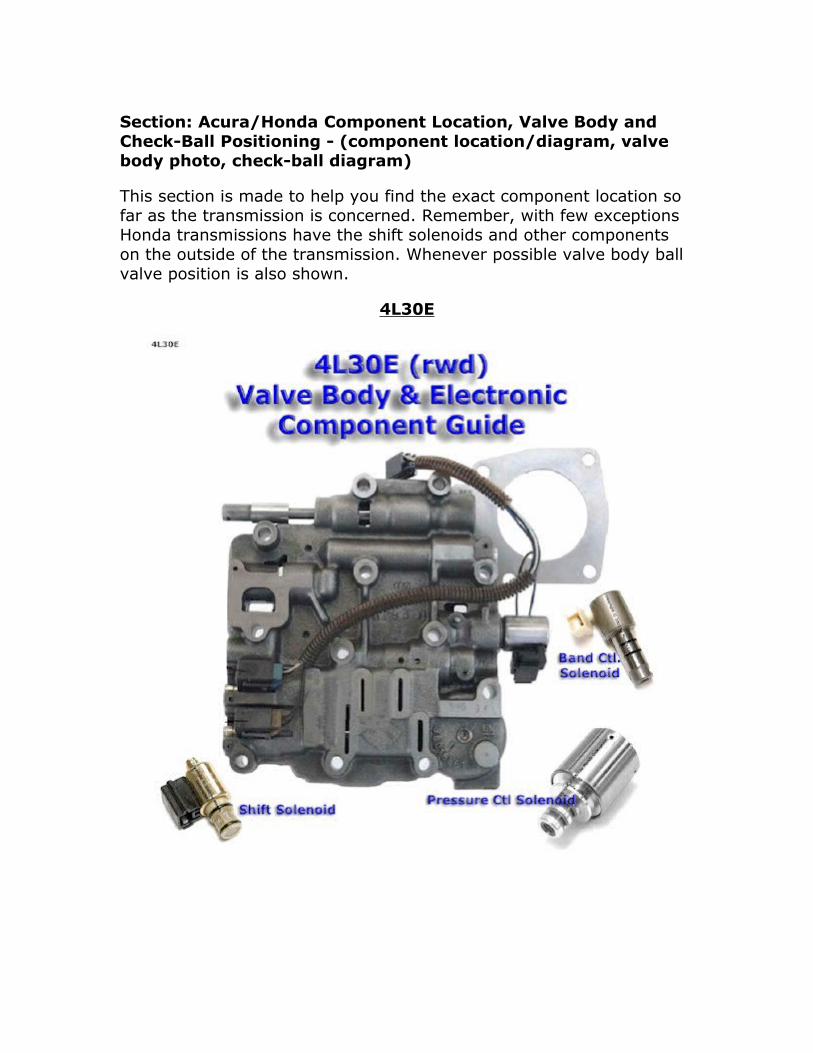
Section: Acura/Honda Component Location, Valve Body and Check-Ball Positioning - (component location/diagram, valve body photo, check-ball diagram)
This section is made to help you find the exact component location so far as the transmission is concerned. Remember, with few exceptions Honda transmissions have the shift solenoids and other components on the outside of the transmission. Whenever possible valve body ball valve position is also shown.
4L30E


B7TA/B7YA
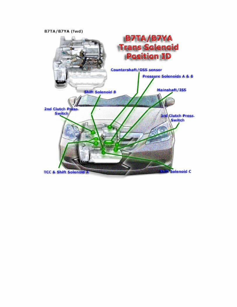
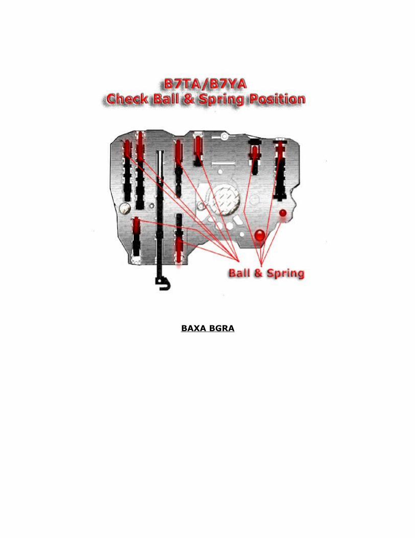
BAXA BGRA
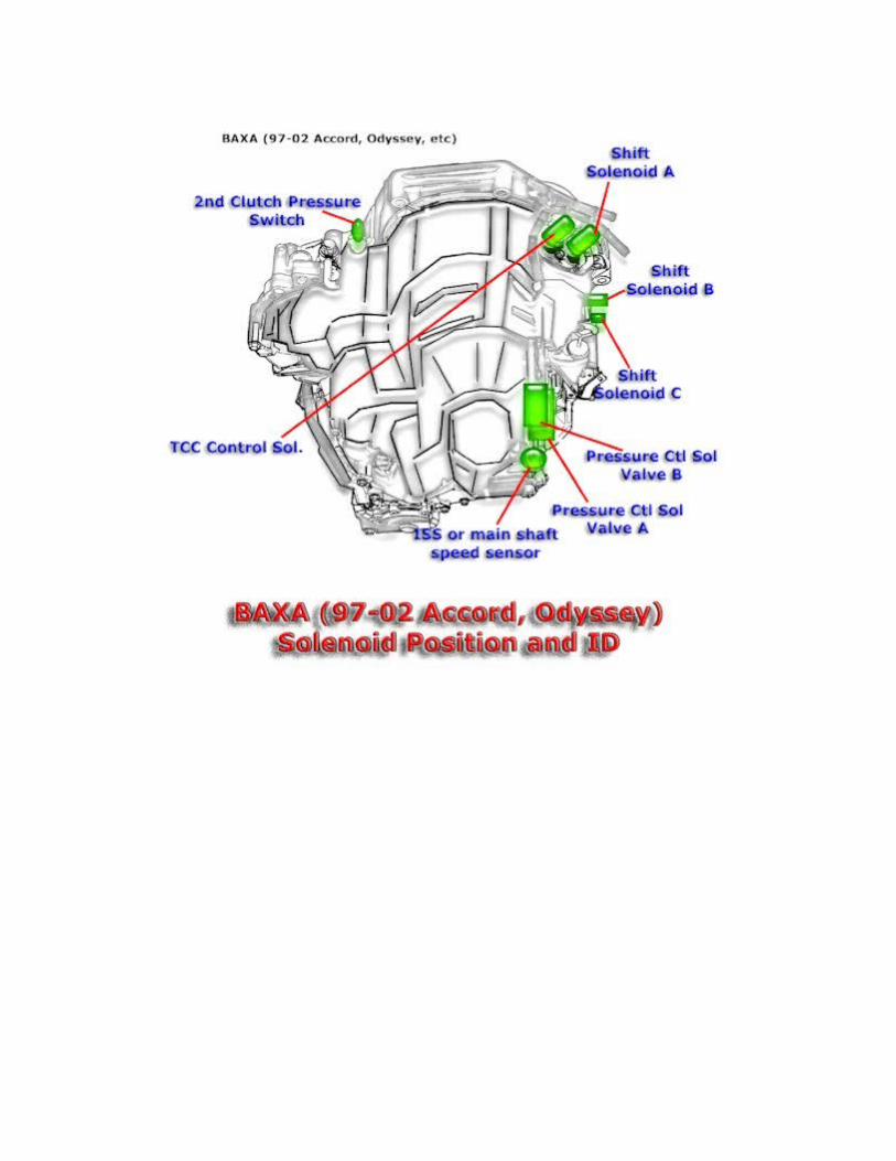
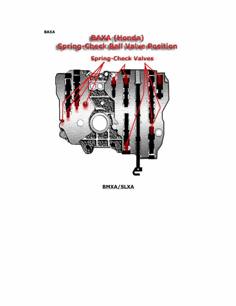
BMXA/SLXA

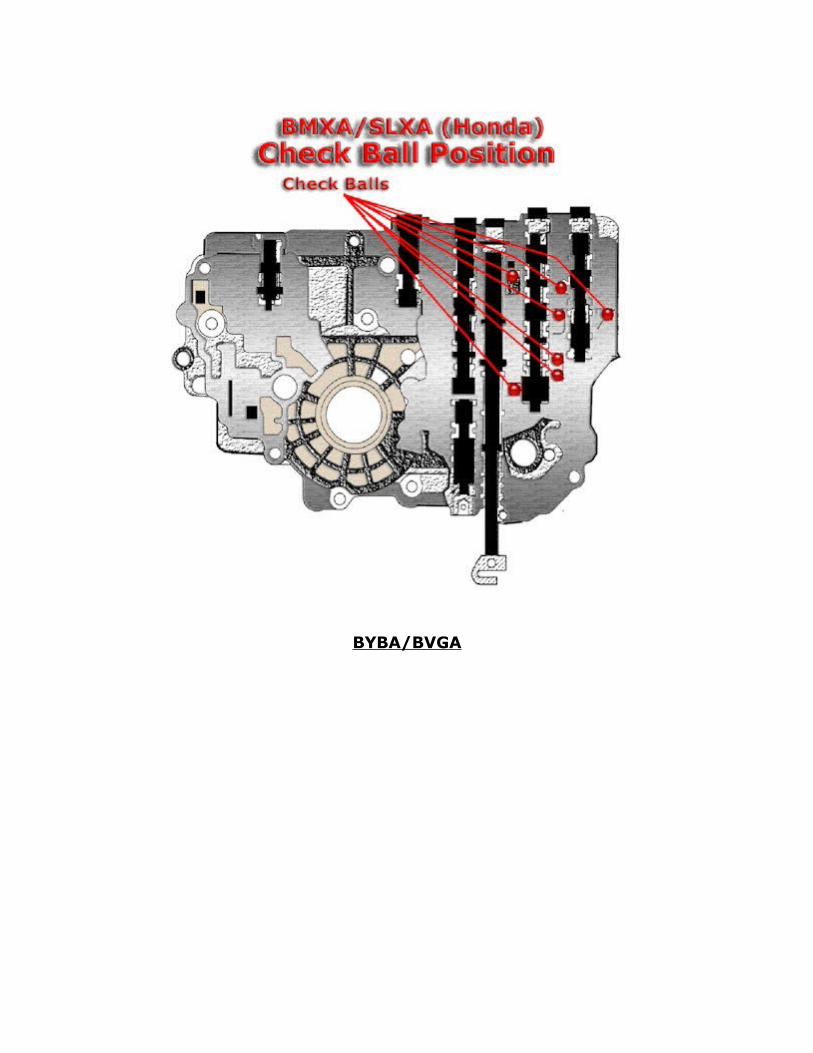
BYBA/BVGA
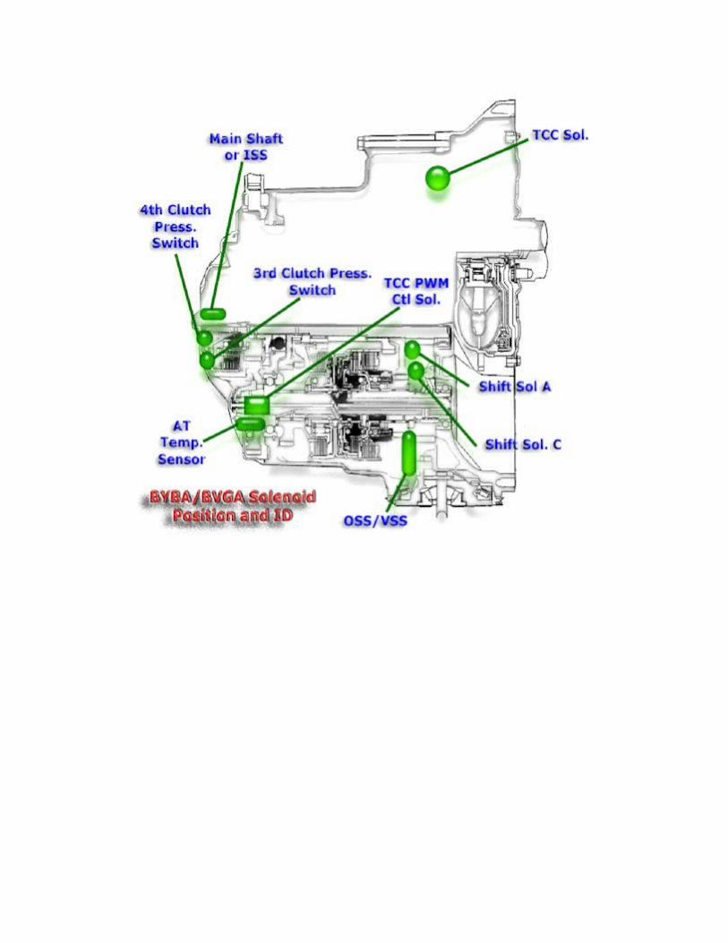
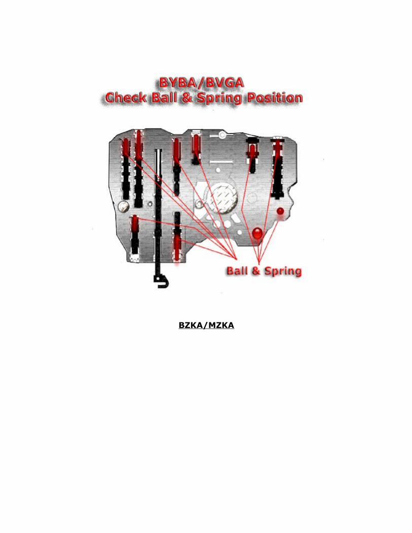
BZKA/MZKA

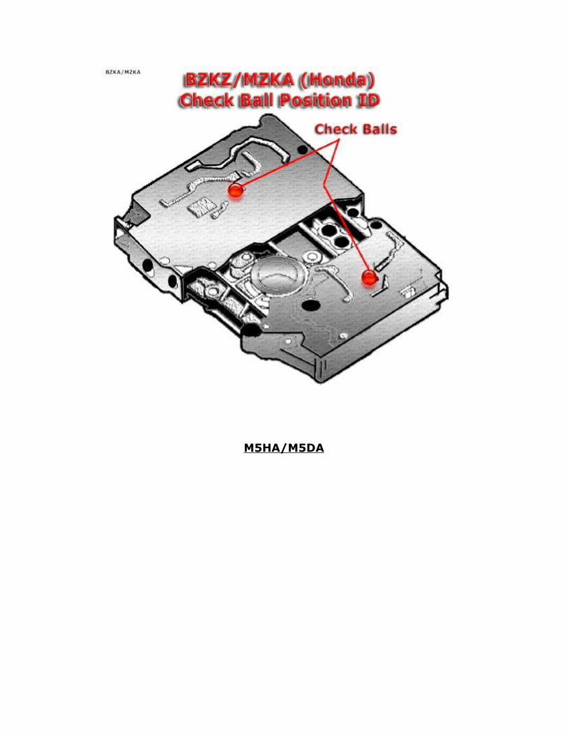
M5HA/M5DA
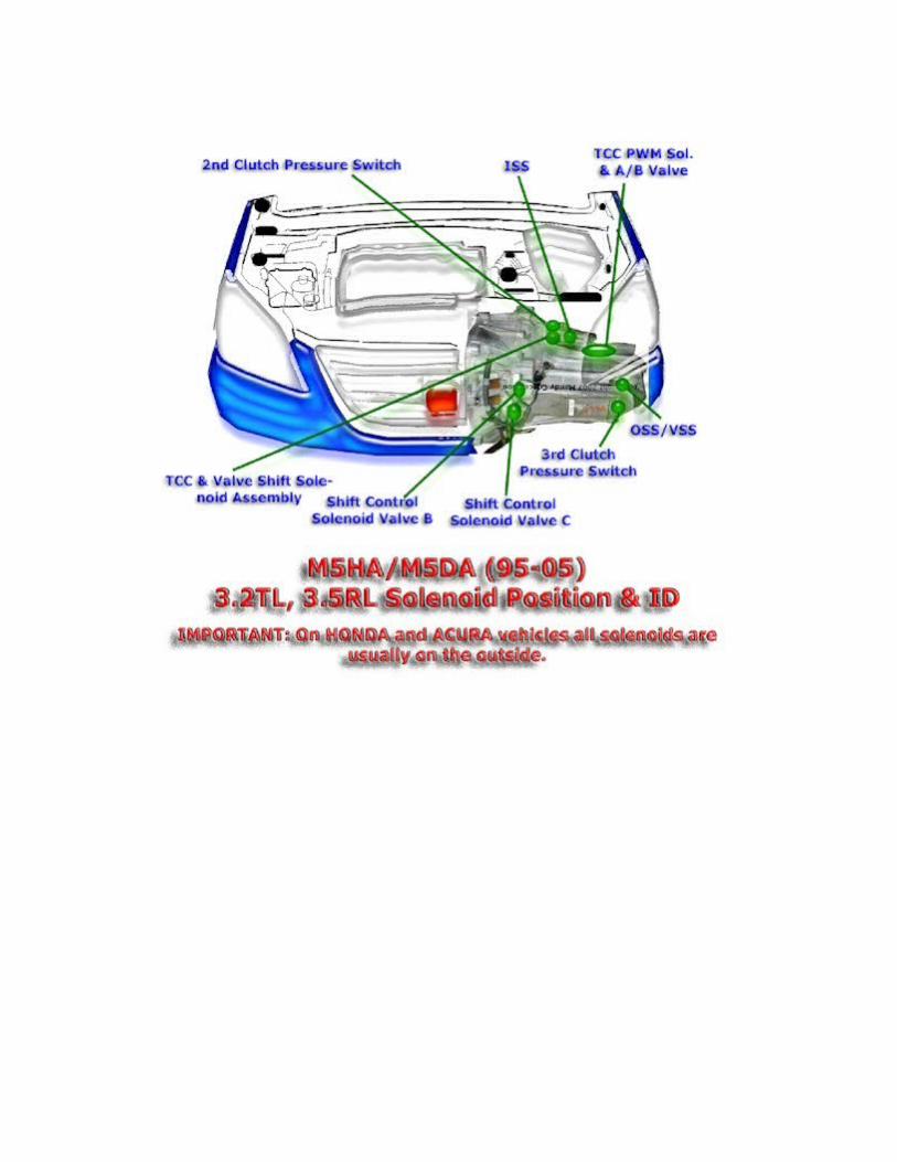

M6HA
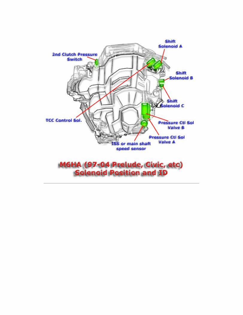

M7WA/MGFA

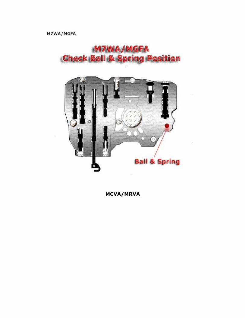
MCVA/MRVA

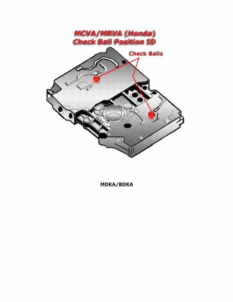
MDKA/BDKA
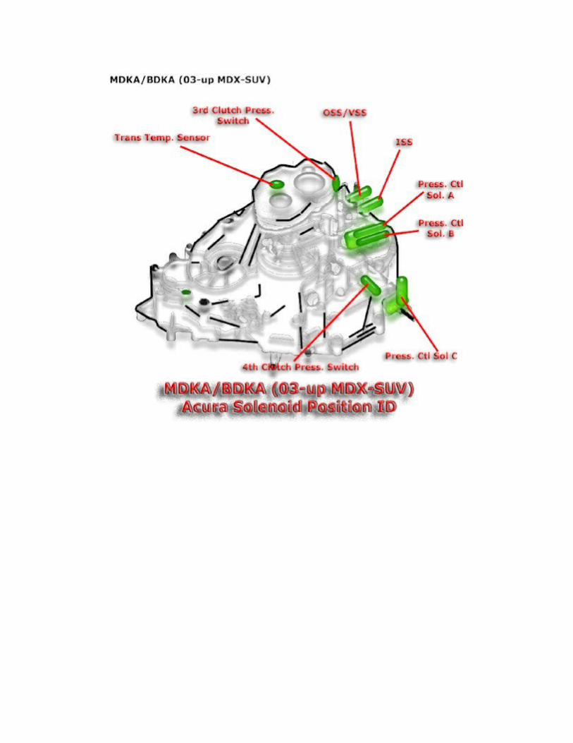
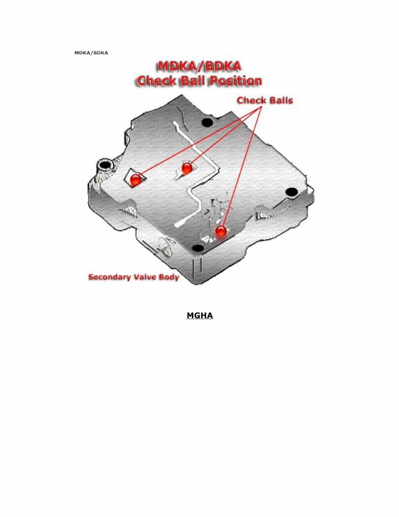
MGHA
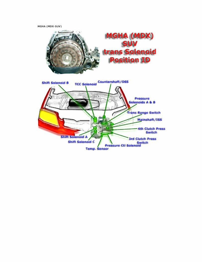

MKYA


MP1A
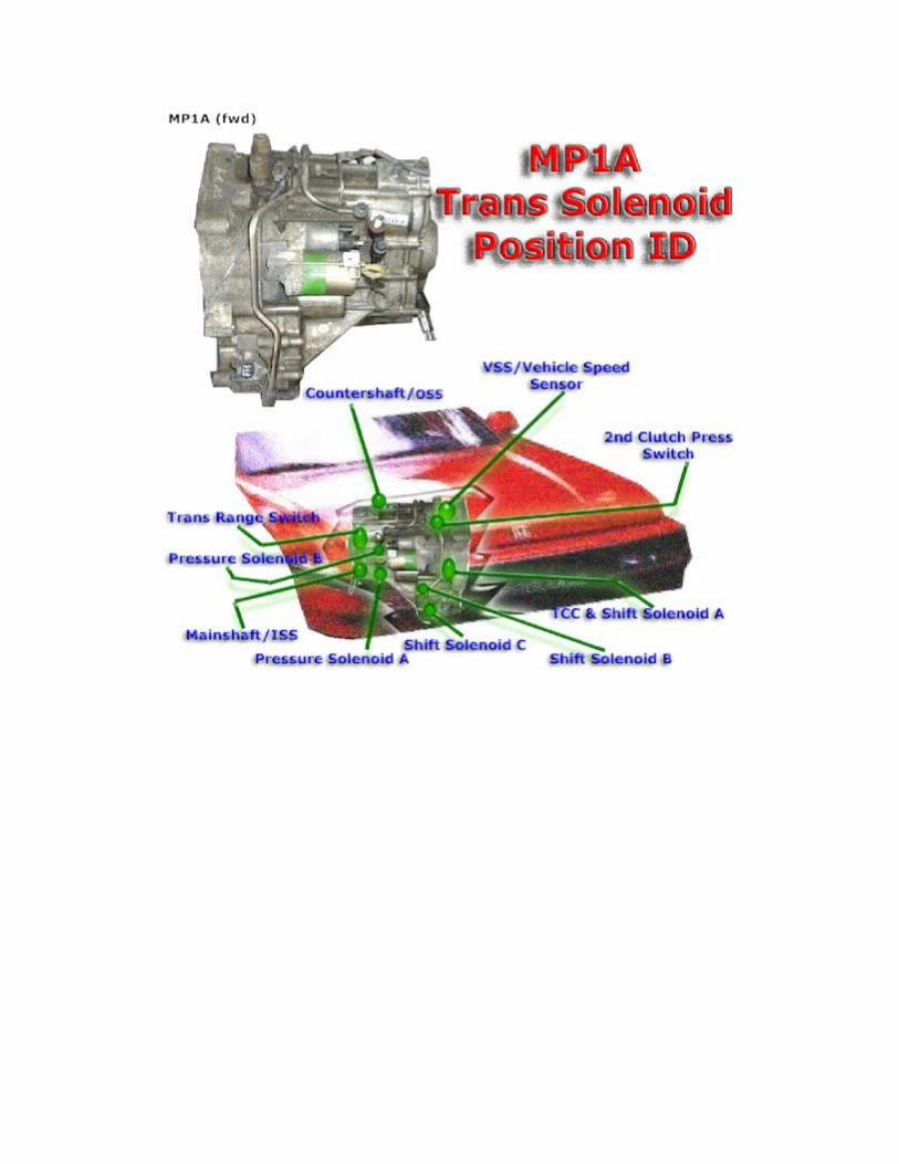

This book is based on the "Automotive Transmission Troubleshooter" software by the same author. All similarities to this software package are intended. Both of these products are copyrighted by the author, Mandy Concepcion. For further insight on automotive transmissions please see our complementary DVD-Video.
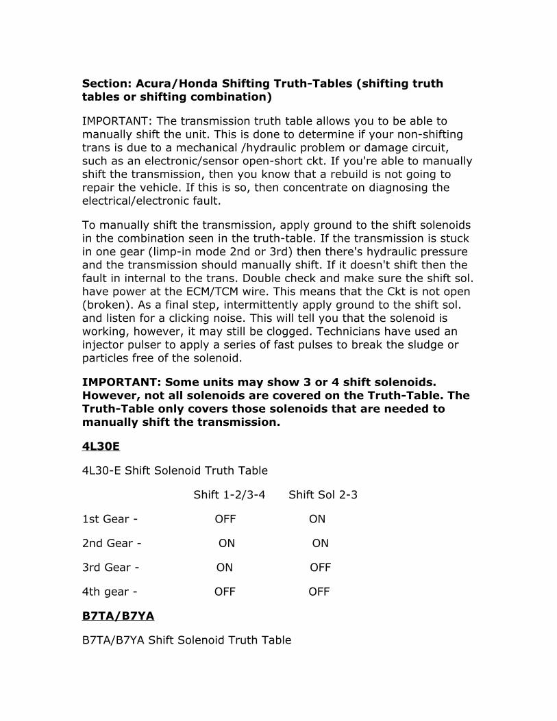
Section: Acura/Honda Shifting Truth-Tables (shifting truth tables or shifting combination)
IMPORTANT: The transmission truth table allows you to be able to manually shift the unit. This is done to determine if your non-shifting trans is due to a mechanical /hydraulic problem or damage circuit, such as an electronic/sensor open-short ckt. If you're able to manually shift the transmission, then you know that a rebuild is not going to repair the vehicle. If this is so, then concentrate on diagnosing the electrical/electronic fault.
To manually shift the transmission, apply ground to the shift solenoids in the combination seen in the truth-table. If the transmission is stuck in one gear (limp-in mode 2nd or 3rd) then there's hydraulic pressure and the transmission should manually shift. If it doesn't shift then the fault in internal to the trans. Double check and make sure the shift sol. have power at the ECM/TCM wire. This means that the Ckt is not open (broken). As a final step, intermittently apply ground to the shift sol. and listen for a clicking noise. This will tell you that the solenoid is working, however, it may still be clogged. Technicians have used an injector pulser to apply a series of fast pulses to break the sludge or particles free of the solenoid.
IMPORTANT: Some units may show 3 or 4 shift solenoids. However, not all solenoids are covered on the Truth-Table. The Truth-Table only covers those solenoids that are needed to manually shift the transmission.
4L30E
4L30-E Shift Solenoid Truth Table
Shift 1-2/3-4 Shift Sol 2-3
1st Gear - OFF ON
2nd Gear - ON ON
3rd Gear - ON OFF
4th gear - OFF OFF
B7TA/B7YA
B7TA/B7YA Shift Solenoid Truth Table
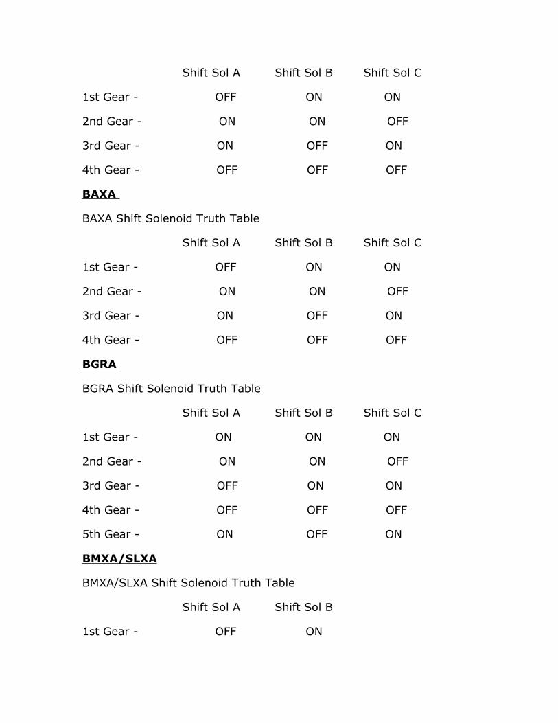
Shift Sol A Shift Sol B Shift Sol C
1st Gear - OFF ON ON
2nd Gear - ON ON OFF
3rd Gear - ON OFF ON
4th Gear - OFF OFF OFF
BAXA
BAXA Shift Solenoid Truth Table
Shift Sol A Shift Sol B Shift Sol C
1st Gear - OFF ON ON
2nd Gear - ON ON OFF
3rd Gear - ON OFF ON
4th Gear - OFF OFF OFF
BGRA
BGRA Shift Solenoid Truth Table
Shift Sol A Shift Sol B Shift Sol C
1st Gear - ON ON ON
2nd Gear - ON ON OFF
3rd Gear - OFF ON ON
4th Gear - OFF OFF OFF
5th Gear - ON OFF ON
BMXA/SLXA
BMXA/SLXA Shift Solenoid Truth Table
Shift Sol A Shift Sol B
1st Gear - OFF ON
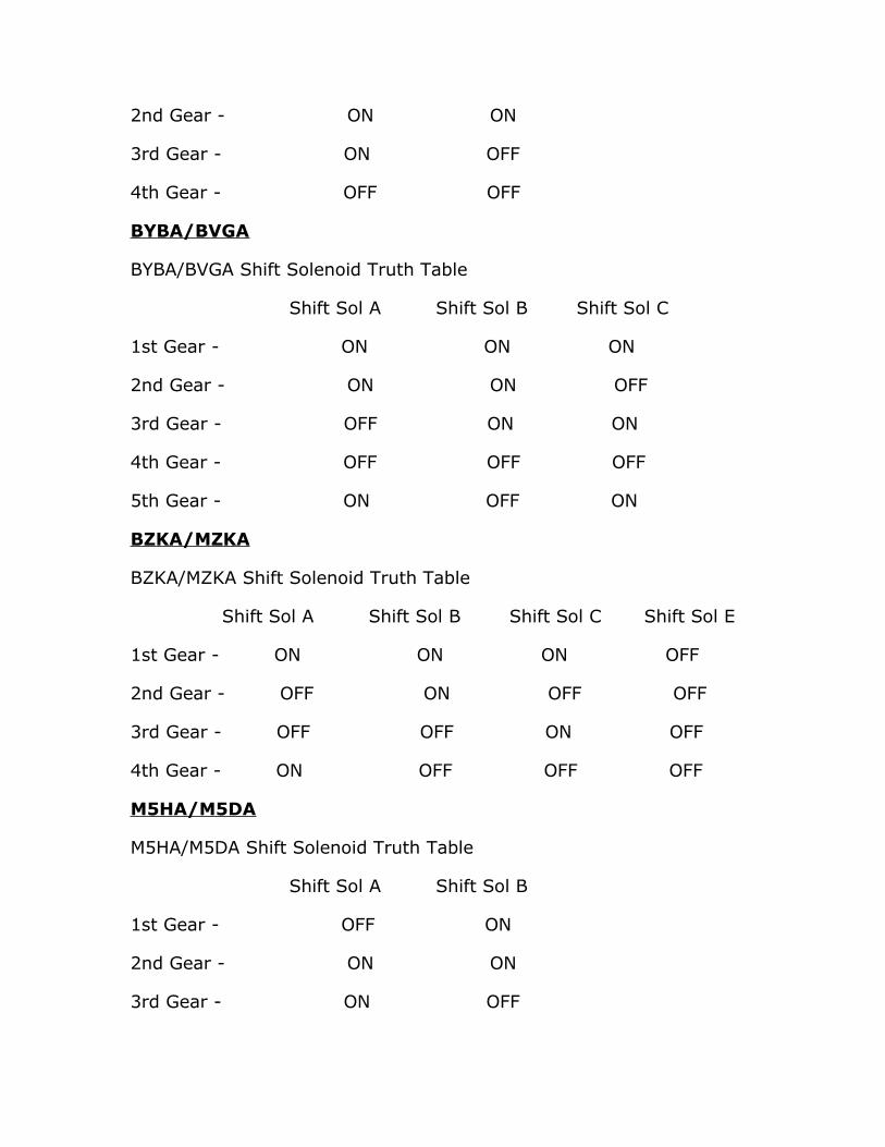
2nd Gear - ON ON
3rd Gear - ON OFF
4th Gear - OFF OFF
BYBA/BVGA
BYBA/BVGA Shift Solenoid Truth Table
Shift Sol A Shift Sol B Shift Sol C
1st Gear - ON ON ON
2nd Gear - ON ON OFF
3rd Gear - OFF ON ON
4th Gear - OFF OFF OFF
5th Gear - ON OFF ON
BZKA/MZKA
BZKA/MZKA Shift Solenoid Truth Table
Shift Sol A Shift Sol B Shift Sol C Shift Sol E
1st Gear - ON ON ON OFF
2nd Gear - OFF ON OFF OFF
3rd Gear - OFF OFF ON OFF
4th Gear - ON OFF OFF OFF
M5HA/M5DA
M5HA/M5DA Shift Solenoid Truth Table
Shift Sol A Shift Sol B
1st Gear - OFF ON
2nd Gear - ON ON
3rd Gear - ON OFF
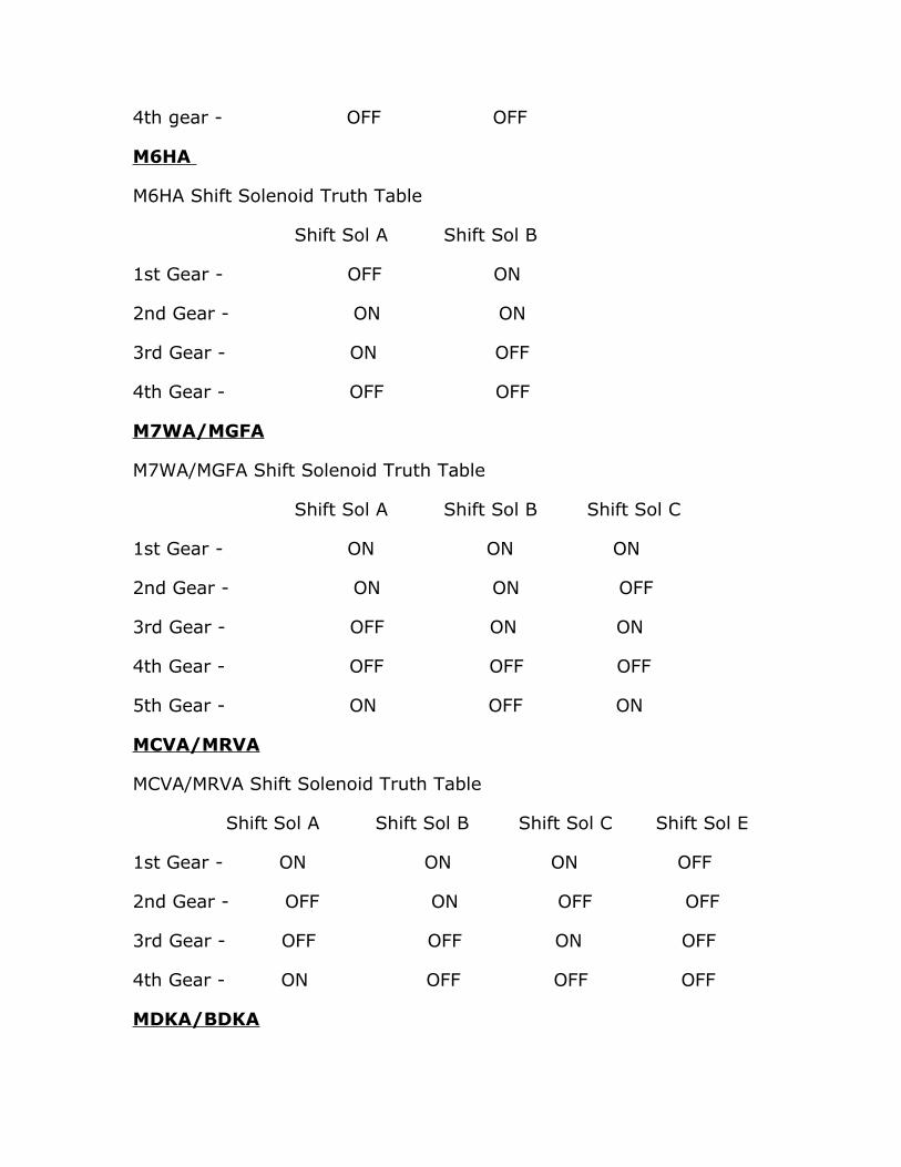
4th gear - OFF OFF
M6HA
M6HA Shift Solenoid Truth Table
Shift Sol A Shift Sol B
1st Gear - OFF ON
2nd Gear - ON ON
3rd Gear - ON OFF
4th Gear - OFF OFF
M7WA/MGFA
M7WA/MGFA Shift Solenoid Truth Table
Shift Sol A Shift Sol B Shift Sol C
1st Gear - ON ON ON
2nd Gear - ON ON OFF
3rd Gear - OFF ON ON
4th Gear - OFF OFF OFF
5th Gear - ON OFF ON
MCVA/MRVA
MCVA/MRVA Shift Solenoid Truth Table
Shift Sol A Shift Sol B Shift Sol C Shift Sol E
1st Gear - ON ON ON OFF
2nd Gear - OFF ON OFF OFF
3rd Gear - OFF OFF ON OFF
4th Gear - ON OFF OFF OFF
MDKA/BDKA
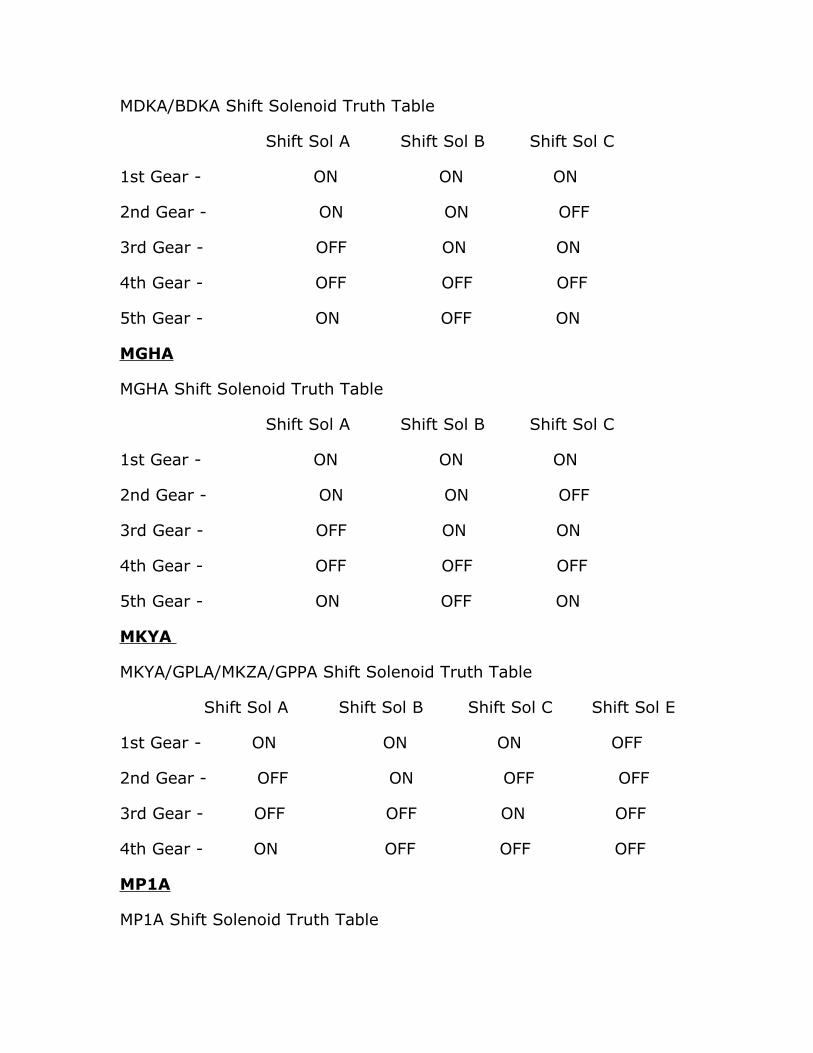
MDKA/BDKA Shift Solenoid Truth Table
Shift Sol A Shift Sol B Shift Sol C
1st Gear - ON ON ON
2nd Gear - ON ON OFF
3rd Gear - OFF ON ON
4th Gear - OFF OFF OFF
5th Gear - ON OFF ON
MGHA
MGHA Shift Solenoid Truth Table
Shift Sol A Shift Sol B Shift Sol C
1st Gear - ON ON ON
2nd Gear - ON ON OFF
3rd Gear - OFF ON ON
4th Gear - OFF OFF OFF
5th Gear - ON OFF ON
MKYA
MKYA/GPLA/MKZA/GPPA Shift Solenoid Truth Table
Shift Sol A Shift Sol B Shift Sol C Shift Sol E
1st Gear - ON ON ON OFF
2nd Gear - OFF ON OFF OFF
3rd Gear - OFF OFF ON OFF
4th Gear - ON OFF OFF OFF
MP1A
MP1A Shift Solenoid Truth Table

Shift Sol A Shift Sol B
1st Gear - OFF ON
2nd Gear - ON ON
3rd Gear - ON OFF
4th Gear - OFF OFF
This book is based on the "Automotive Transmission Troubleshooter" software by the same author. All similarities to this software package are intended. Both of these products are copyrighted by the author, Mandy Concepcion .For further insight on automotive transmissions please see our complementary DVD-Video.
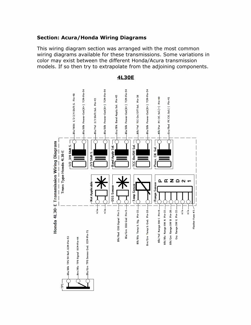
Section: Acura/Honda Wiring Diagrams
This wiring diagram section was arranged with the most common wiring diagrams available for these transmissions. Some variations in color may exist between the different Honda/Acura transmission models. If so then try to extrapolate from the adjoining components.
4L30E
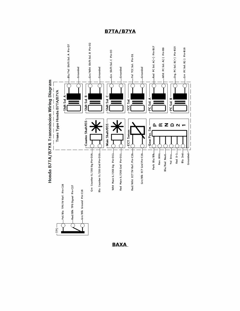
B7TA/B7YA
BAXA

BGRA
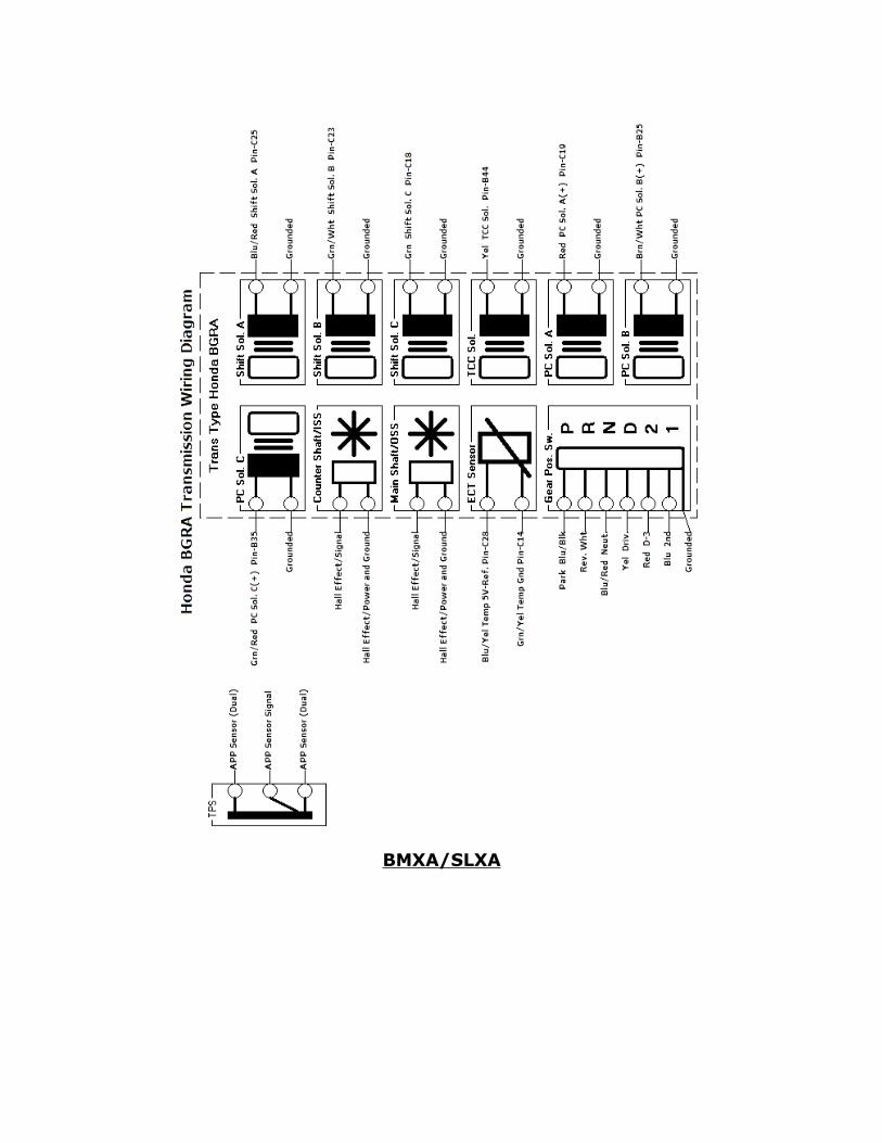
BMXA/SLXA

BYBA/BVGA
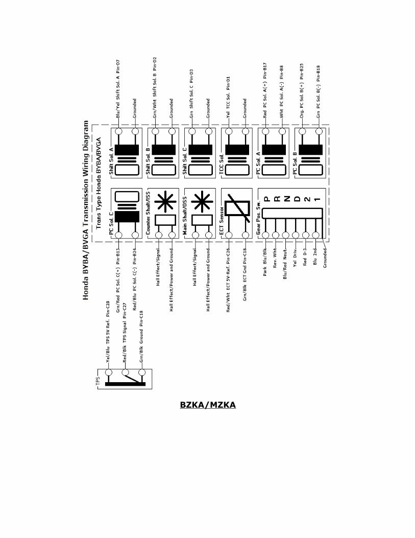
BZKA/MZKA

M5HA/M5DA

M6HA
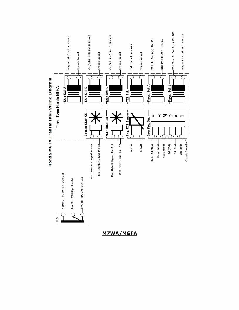
M7WA/MGFA
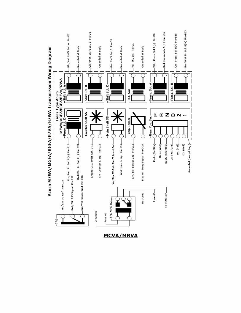
MCVA/MRVA

MDKA/BDKA
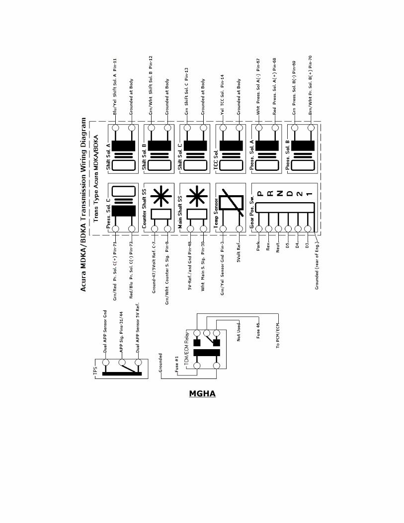
MGHA

MKYA

MP1A
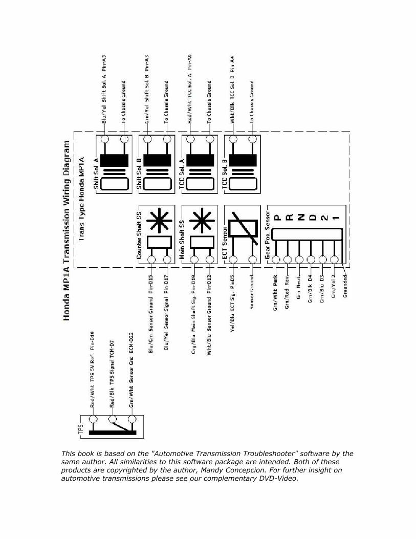
This book is based on the "Automotive Transmission Troubleshooter" software by the same author. All similarities to this software package are intended. Both of these products are copyrighted by the author, Mandy Concepcion. For further insight on automotive transmissions please see our complementary DVD-Video.
Discover other titles by Mandy Concepcion
Section: About the Author:
Mandy Concepcion has worked in the automotive field for over 21 years. He holds an Associates Degree in Applied Electronics Engineering as well as an ASE L1 certification. For the past 12 years he has been exclusively involved in the diagnosis of all the different electronic systems found in today’s vehicles. It is here where he draws extensive practical knowledge from his experience and hopes to convey it in this book.
This book is based on the "Automotive Transmission Troubleshooter" software by the same author. All similarities to this software package are intended. Both of these products are copyrighted by the author, Mandy Concepcion. For further insight on automotive transmissions please see our complementary DVD-Video.