disclosure clinical use of respiratory correlated ct imaging · clinical use of respiratory...
TRANSCRIPT

Clinical Use of Respiratory Correlated CT Imaging
Sasa Mutic
Department of Radiation OncologyMallinckrodt Institute of Radiology
Siteman Cancer Center Washington University School of Medicine
St. Louis, Missouri 63110
Disclosure
• Other faculty at the Washington University School of Medicine Department of Radiation Oncology have research grants from Philips Medical Systems
• The presenter is not directly supported by these grants
Learning Objectives
• To demonstrate the need for commissioning and understanding of respiratory correlated CT imaging systems and processes
• Respiratory correlated imaging and treatment delivery can significantly improve accuracy and conformality of dose distributions delivered to moving targets
• While this presentation will mainly demonstrate pitfalls and artifacts associated with respiratory correlated imaging, it is in no way intended to discourage clinical use of this technology
• An purpose of the presentation is to promote safe and accurate use of this technology
The Need to Gate
Static Dynamic Dynamic
Dynamic

Terms
CT Imaging• Axial & Spiral CT• Single-slice & Multi-
slice CT• Collimation• Coverage (detector
width)• Pitch• Temporal resolution
Dynamic CT Imaging• Waveform• Tag• Phase• Amplitude• MIP• MinIP• AvgIP• Sub-phase (MIP, MinIP)• Prospective• Retrospective
Commissioning and QA
• Three stages of QA/Commissioning–CT Scanner Commissioning–Treatment Delivery Commissioning–Patient Specific QA
»During Imaging»Treatment Planning»Daily Treatments
Scanner QA
Gating QA procedure
• Qualitative gating QA (do things look right?)–Is motion compensated for?–Are inhale and exhale really inhale
and exhale?–Identify patient breathing
characteristics that will cause system failure
• Quantitative gating QA –Phases accurate–Verify MIP generation
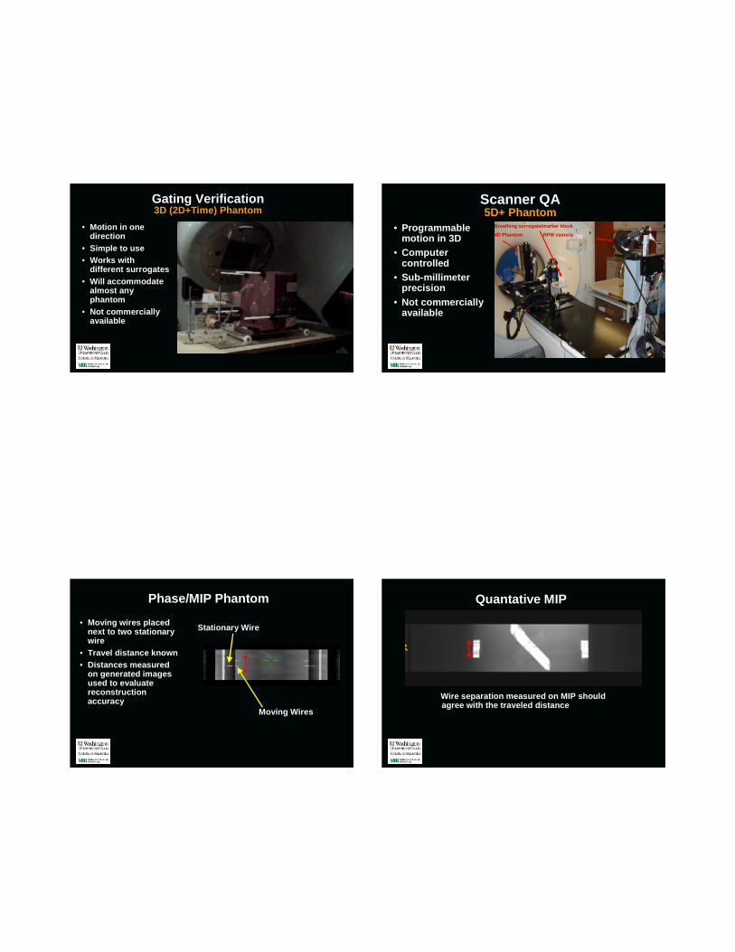
Gating Verification3D (2D+Time) Phantom
• Motion in one direction
• Simple to use• Works with
different surrogates• Will accommodate
almost any phantom
• Not commercially available
Scanner QA5D+ Phantom
• Programmable motion in 3D
• Computer controlled
• Sub-millimeter precision
• Not commercially available
Breathing surrogate/marker block
4D Phantom RPM camera
Phase/MIP Phantom
• Moving wires placed next to two stationary wire
• Travel distance known• Distances measured
on generated images used to evaluate reconstruction accuracy
Stationary Wire
Moving Wires
Quantative MIP
Wire separation measured on MIP should agree with the traveled distance

Phase Verification
50%
60%
70%
90%
50%
60%
70%
90%
Patient Specific QA - Imaging
Pitch

0.0650.07510
0.070.0811
0.080.0912
0.0850.0913
0.090.10514
0.10.1115
0.120.1520
For 0.44 sec Rotation Time, use a pitch no higher than:
For 0.5 sec Rotation Time, use a pitch no higher than:
Breath Rate (in breaths per minute)
Rotation Time(secs) x Breath Rate(breaths/min)
60 ( seconds/min)
Choosing optimal pitch based on breathing rate
Image review and artifacts Wrong PitchWrong Pitch
Mid-Scan Breathing Rate Slows
Breathing rate slows during scan acquisition
Image review and artifacts Big Pause

Mid-Scan Amplitude Change Mid-Scan Amplitude Change
Mid-Scan Amplitude Change Image review and artifacts Heart

Intensity-Projection-over-phases
8
MIP MinIP
Avg
Image review and artifacts Dangers of MIP
Image review and artifacts Dangers of MIP Data Set Registration
Patient movement – between scans
Free Breathing Fused MIP

Image Reconstruction – Subset-MIP
• RPM gating on linac is performed during portion of breathing cycle
• Reconstruct ITV (MIP) that best represents portion of breathing cycle when beam is on
Beam ON
40% 60%
Breathing Traces
100 200 300 400 500 600 700 800-100
0
100
200
300
400
500
600
700
800
Time (s)
Tid
al V
olum
e (m
l)
Breathing Trace - Curve Fit Demonstration
100 200 300 400 500 600 700 800 900-200
0
200
400
600
800
1000
Time (s)
Tid
al V
olum
e (m
l)
Breathing Trace - Curve Fit Demonstration
Courtesy D.A. Low
Breathing Rate Difference (Coaching Effects)
14 bpm9 bpm
Breathing Rate Difference (Coaching Effects)
14 bpm9 bpm MIP
9 mm difference

Conclusions
• Respiration correlated imaging and delivery hardware and software relatively robust
• Inadequate processes and understanding main source of concerns
• Individual patient data sets review imperative
• Respiration correlated delivery only with daily validation of gating window
• We only gate patients who have targets, stents, or fiducial markers visible on fluoroscopic imaging
Special Thanks To:
• Camille Noel• James Hubenschmidt• Daniel A. Low• S. Murty Goddu• Lakshmi Santanam• Parag Parikh