disclaimer - site readiness - ge healthcare
TRANSCRIPT
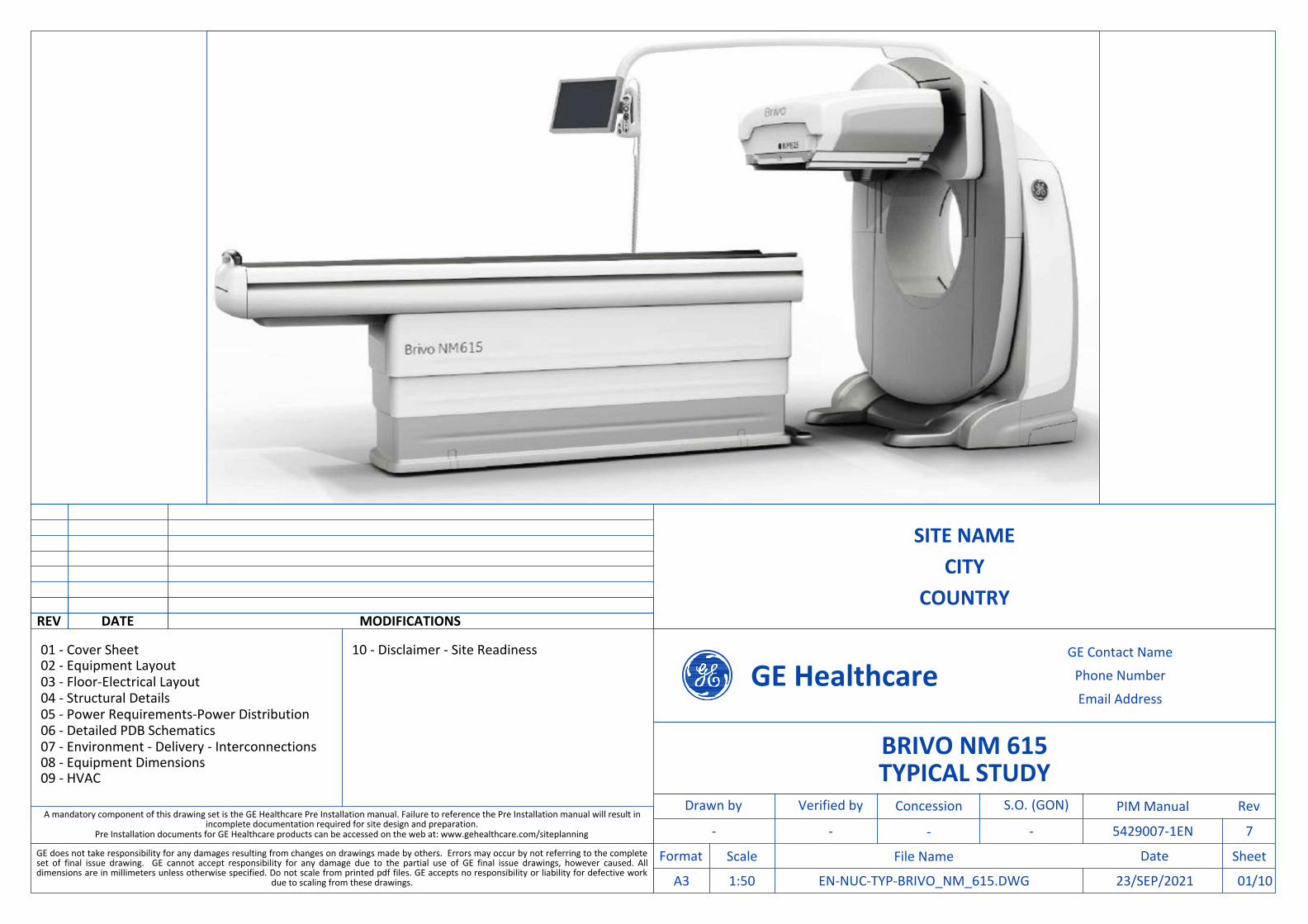
01 - Cover Sheet 02 - Equipment Layout 03 - Floor-Electrical Layout 04 - Structural Details 05 - Power Requirements-Power Distribution 06 - Detailed PDB Schematics 07 - Environment - Delivery - Interconnections 08 - Equipment Dimensions 09 - HVAC
CITY
GE Contact Name
BRIVO NM 615
-
GE Healthcare
GE does not take responsibility for any damages resulting from changes on drawings made by others. Errors may occur by not referring to the completeset of final issue drawing. GE cannot accept responsibility for any damage due to the partial use of GE final issue drawings, however caused. Alldimensions are in millimeters unless otherwise specified. Do not scale from printed pdf files. GE accepts no responsibility or liability for defective work
due to scaling from these drawings. /10EN-NUC-TYP-BRIVO_NM_615.DWG
Phone Number
Email Address
- 5429007-1EN
COUNTRY
1:50
-
23/SEP/2021
SITE NAME
REV DATE MODIFICATIONS
A mandatory component of this drawing set is the GE Healthcare Pre Installation manual. Failure to reference the Pre Installation manual will result inincomplete documentation required for site design and preparation.
Pre Installation documents for GE Healthcare products can be accessed on the web at: www.gehealthcare.com/siteplanning -
Drawn by Verified by PIM Manual
SheetFormat
Concession
Scale DateFile Name
RevS.O. (GON)
A3
7
TYPICAL STUDY
01
10 - Disclaimer - Site Readiness

LEHR COLLIMATOR (1 PER SYSTEM/CART) - 62 kg
LEGP COLLIMATOR (1 PER SYSTEM/CART) - 55 kg
MEGP COLLIMATOR (1 PER SYSTEM/CART) - 103 kg
HEGP COLLIMATOR (1 PER SYSTEM/CART) - 131 kg
ELEGP COLLIMATOR (1 PER SYSTEM/CART) - 62 kg
COLLIMATOR OPTIONS
ITEM DESCRIPTION DIMENSIONSLxWxH (mm)
WEIGHT(kg)
1 GANTRY 2070x1530x2110 1595
2 PATIENT TABLE 2809x528x1000 360
3 COLLIMATOR CART (WITHOUT COLLIMATORS) 500x970x1458 68
4 MAIN DISCONNECT PANEL (MDP) 146x406x610 23
5 INJECTOR CONTROL - -
6 ECG MONITOR - 3
7 INJECTOR ON PEDESTAL - -
8 XELERIS WORKSTATION (WITH TWO LCD MONITORS) - 30
9 NM AQUISITION STATION 445x169x386 11.3
WALL - ACCORDING TO RECEIVED DRAWING
EXAM ROOM HEIGHT
FINISHED FLOOR TO SLAB HEIGHT
FALSE CEILING HEIGHT
-
min. 2.25 m
EQUIPMENT LAYOUT
DateRev /10EN-NUC-TYP-BRIVO_NM_615.DWG A 23/SEP/2021BRIVO NM 615SITE NAME Equipment Layout 021:50
55001500
5000
1400900
20302115
CONTROL AREAEXAM ROOM
27.50 m²
12
4
6
7
3
8
9
5
67.5°
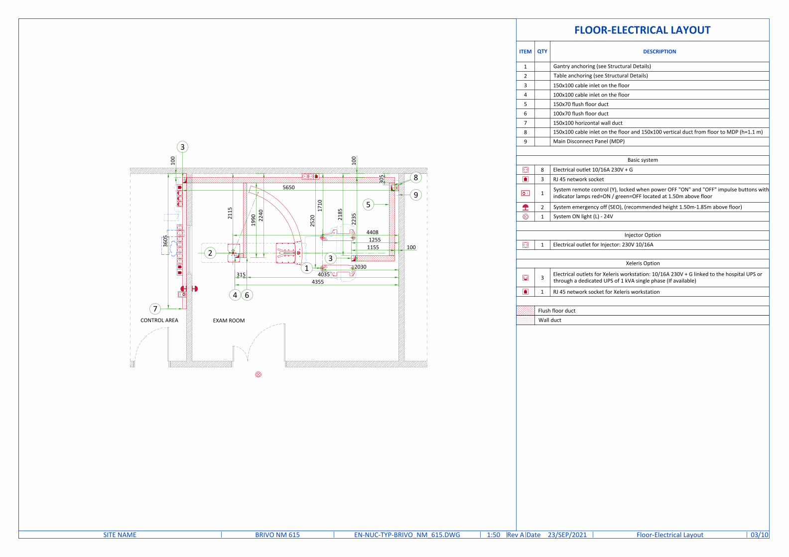
Flush floor duct
Wall duct
Injector Option
Electrical outlet for Injector: 230V 10/16A1
Xeleris Option
3 Electrical outlets for Xeleris workstation: 10/16A 230V + G linked to the hospital UPS orthrough a dedicated UPS of 1 kVA single phase (If available)
1 RJ 45 network socket for Xeleris workstation
Basic system
Electrical outlet 10/16A 230V + G
RJ 45 network socket
System remote control (Y), locked when power OFF "ON" and "OFF" impulse buttons withindicator lamps red=ON / green=OFF located at 1.50m above floor
System emergency off (SEO), (recommended height 1.50m-1.85m above floor)
System ON light (L) - 24V
8
3
1
2
1
ITEM QTY DESCRIPTION
1 Gantry anchoring (see Structural Details)
2 Table anchoring (see Structural Details)
3 150x100 cable inlet on the floor4 100x100 cable inlet on the floor5 150x70 flush floor duct6 100x70 flush floor duct7 150x100 horizontal wall duct8 150x100 cable inlet on the floor and 150x100 vertical duct from floor to MDP (h=1.1 m)
9 Main Disconnect Panel (MDP)
FLOOR-ELECTRICAL LAYOUT
DateRev /10EN-NUC-TYP-BRIVO_NM_615.DWG A 23/SEP/2021BRIVO NM 615SITE NAME Floor-Electrical Layout 031:50
2030
2520
1710
1155 1001255
2185
2235
100
5650
3605
100
2115
4408
40353154355
1990 22
401
2
4 6
3
5
3
7CONTROL AREA EXAM ROOM
305
9
8

LOADING DISTRIBUTION TO THE FLOOR
Gantry weight: 1595 kg [3517 lb](with HEGPcollimators mounted)Table weight: 360 kg [794 lb]
Center of gravity
Load 360 kg [794 lb]distributed on 2wheels +pivot
Gantry rear pads283.5 kg [625 lb]load per padØ83 [Ø3.3 in]
SCALE 1:25
Gantry front pads514 kg [1133 lb] loadper Ø83 [Ø3.3 in] pad
810[32in]
405
[16
in]
405
[16
in]
288[11 in]
1656[65in]
Gantry weight: 1595 kg [3517 lb](with HEGPcollimators mounted)
TYPICAL CABLE MANAGEMENT
FLUSH FLOOR DUCT
Waterproof joint removable coverDividers as requiredper local code
NOT TO SCALE
Removable coverplate
WALL DUCT
Dividers as requiredper local code
ANCHORING TO THE FLOOR
MAIN ANCHORING POINT
ALTERNATIVE ANCHORING POINT
2224[88in]
100[4in]
1135[45in]
405
[16i
n]36
5[1
4in]
80 [3in]
810[32in]
530
[21i
n]
32 [1in]
405
[16i
n]36
5[1
4in]
405
[16i
n]53
0 [2
1in]
NM gantryanchor points4 x HILTI-HSL-3M10/40 anchors
Cable inletarea
Cable inlet area
405
[16i
n]
104 [4in]
73 [3in
]
SCALE 1:25
Table anchor plate6 x Hex Head SleeveBolt 0.25" x 1.75"
Ø15 [Ø0.6 in] depth 35 mm [1.4 in]pocket for collimator cart pin
2789 [110in]
105
[4in
]
Alternativecable inlet area
FLOOR SPECIFICATIONS
NOT TO SCALE
Min
140
mm
[Min
5.5
in]
88 m
m[3
.5 in
]
78 m
m[3
in]
HILTI-HSL-3 M10/40 anchorTorque: 35 Nm
GANTRY ANCHORING
Leveling pad
Gantrystationary base
Leveling screw
Anchor washerNut
Anchor bolt · Floor leveling area: 512 cm [201.6 in] x 374cm [147.2 in] (covering the entire plannedarea of table and gantry surface).
· Slope less than 13 mm [0.5 in] over 4300mm [160 in], if slope is between 13 mm [0.5in] and 30 mm [1.18 in] refer to PIM foradditional requirements.
· Flatness: the surface must be smooth, withdeviations of no more than 5 mm [0.195 in]between depressions and high spots in any1500 mm [59 in] throughout the room orsystem installation area.
· Floor surface: a single poured surface.· Floor strength: in order to enable mounting
of the system floor anchors, concrete floorsmust have a minimum cube strength off'c=4350 psi. (30 MPa) at 28 days (curingtime) for 25/30 concrete
· Floor thickness: the system's floor anchorsare designed for use only on concrete floorsthat meet the minimal 140 mm [5.5 in]concrete floor requirements
· The selected anchoring method must have apulling tensile force of 19.7 kN on each ofthe anchors bolting the NM gantry to thefloor.
DateRev /10EN-NUC-TYP-BRIVO_NM_615.DWG A 23/SEP/2021BRIVO NM 615SITE NAME Floor Structural Details 04

POWER DISTRIBUTION
Notes :(1) 3 x 10 mm² [8 AWG] cable with a usable length of
10 m [32.8 ft] is delivered with the system.If needed, a 19 m [62.3 ft] cable is available as a spare part.
(2) GE gantry contains transformer with multiple taps that canaccommodate listed voltages.
L1 L2G
{Incoming power supply(173-250 VAC)1 Phase + GND
Remote EPO(optional)
30A Main DisconnectPanel (MDP/A1)
Available from GE, see table 1.
NM GANTRY(see note 2)
L1 L2G
See note 1
6 mm² [10 AWG]min. 6 mm²[10 AWG]
4 mm²[12 AWG]
4 mm²[12 AWG]
Table 1: GE Supplied MDP(A1) optionsSystem Region Ecat
Brivo NM615,Discovery NM630,
NM830
EU/EAGM E45011CR/CL
USCANLATAM E4502SV (30A)
Discovery NM630,NM830 UK
E46001TE-PD(Type 5 40A)
Brivo NM615 UKE46001TN-PD(Type 11 40A)
Minimum recommended circuit protection ratings
Volt Amp
173, 190, 200 40A208, 220, 230, 240,250 30A
280 25AY7 x 1.5mm²
[16 AWG]
Remote ControlON/OFF
(Control room, only if neededper local requirements)
Cable SUPPLIED BY CUSTOMER
Equipment SUPPLIED BY GE
Equipment SUPPLIED BYCUSTOMER
Cable SUPPLIED BY GE
POWER REQUIREMENTS
· Line supply should come into a Main Disconnect Panel (MDP) containing the protective units and controls. Thesection of the supply cable should be calculated in accordance with its length and the maximum permissiblevoltage drops, equal to 2.9% max. of regulation for feeder size.
· There must be discrimination between supply cable protective material at the beginning of the installation(main low-voltage transformer side) and the protective devices in the MDP.
SUPPLY CHARACTERISTICS· Power input must be separate from any others which may generate transients (elevators, air conditioning,
radiology rooms equipped with high speed film changers ...)· All equipment (lighting, power outlets, etc...) installed with GE system components must be powered
separately.· Phase imbalance 2% maximum.· Maximum voltage regulation at full load= 6% (including line impedance)· Transients must be less than 1500 V peak (on a 230 V line). A record of power input disturbances over a
continuous one-week period (prior to delivery) enables determination of the frequency and degree of thesedisturbances and can be used to ascertain the need to provide line conditioning equipment.
· Inrush current can withstand up to 10 times the recommended circuit breaker rating that could be reachedduring system power up, due to the system main transformer.
GROUND SYSTEM· Equipotential: The equipotential link will be by means of an equipotential bar. This equipotential bar should
be connected to the protective earth conductors in the ducts of the non GE cableways and to additionalequipotential connections linking up all the conducting units in the rooms where GE system units are located.
CABLES· Power and cable installation must comply with the distribution diagram below.· All cables must be isolated and flexible, cable color codes must comply with standardsfor electrical
installation.· The cables from signaling and remote control (Y, SEO, L ...) will go to MDP with a pigtail length of 1.5 m, and
will be connected during installation. Each conductor will be identified and isolated (screw connector).
CABLEWAYSThe general rules for laying cableways should meet the conditions laid down in current standards and regulations,with regard to :· Protecting cables against water (cableways should be waterproof)· Protecting cables against abnormal temperatures (proximity to heating pipes or ducts)· Protecting cables against temperature shocks· Replacing cables (cableways should be large enough for cables to be replaced)· Metal cableways should be grounded
POWER SUPPLY SINGLE PHASE + N 208-240 VAC ±10%FREQUENCIES 50/60 Hz ± 3 HzMAXIMUM POWER DEMAND 6 kVACONTINUOUS (AVERAGE) POWER DEMAND 2.5 kVA
DateRev /10EN-NUC-TYP-BRIVO_NM_615.DWG A 23/SEP/2021BRIVO NM 615SITE NAME Power Requirements-Power Distribution 05

DETAILED SCHEMATICS OF POWER DISTRIBUTION BOX
PE L N
EARTH BAR
CAMERAGAMMA
Supplied by GE
L N
4 4
TR1250VA230/24V
230V
24V
0 24
2300
MBD1
Type D300mA
C1
IGINTERRUPTER
B12x3AType D
B210A+NType C
SIGNALLINGCONTROL
EMERGENCY OFFBUTTON
IN EXAM ROOM
SEO1
SEO2
OFF
ON
YSYSTEM REMOTE
CONTROLIN CONTROL ROOM
R1 C1
R1
Y
R1 R1
R1
24VAC
H1White24VAC
OFFRed24VAC
ONGreen24VAC
2x50A
2x32A
2x32A
3xAWG8 (8.3mm²)
If length < 12m
GANTRY
3 x 400V3 PHASE MAIN SUPPLY FROM
GENERAL ELECTRIC BOARDMBD1: D type magnetic breakerC1: 24 VAC 50 Hz contactorB1/B2: Circuit breakerR1: 24 VAC 50 Hz relay
EMERGENCY OFFBUTTON
IN CONTROL ROOM
PDB SCHEMATICS AND DETAILS THAT APPEAR ON THIS PAGEARE THE PROPERTY OF "GE MEDICAL SYSTEMS FRANCE"
ON PDBDOOR
DateRev /10EN-NUC-TYP-BRIVO_NM_615.DWG A 23/SEP/2021BRIVO NM 615SITE NAME Detailed PDB Schematics 06
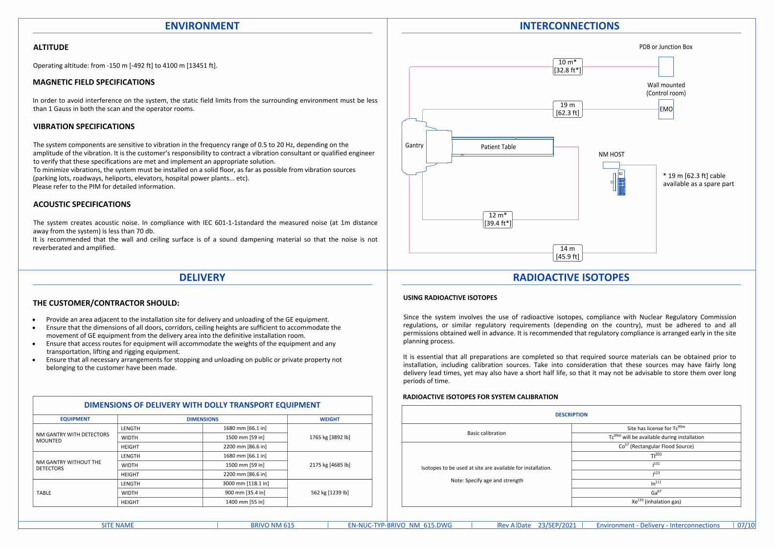
DELIVERY
THE CUSTOMER/CONTRACTOR SHOULD:
· Provide an area adjacent to the installation site for delivery and unloading of the GE equipment.· Ensure that the dimensions of all doors, corridors, ceiling heights are sufficient to accommodate the
movement of GE equipment from the delivery area into the definitive installation room.· Ensure that access routes for equipment will accommodate the weights of the equipment and any
transportation, lifting and rigging equipment.· Ensure that all necessary arrangements for stopping and unloading on public or private property not
belonging to the customer have been made.
DIMENSIONS OF DELIVERY WITH DOLLY TRANSPORT EQUIPMENTEQUIPMENT DIMENSIONS WEIGHT
NM GANTRY WITH DETECTORSMOUNTED
LENGTH 1680 mm [66.1 in]1765 kg [3892 lb]WIDTH 1500 mm [59 in]
HEIGHT 2200 mm [86.6 in]
NM GANTRY WITHOUT THEDETECTORS
LENGTH 1680 mm [66.1 in]2175 kg [4685 lb]WIDTH 1500 mm [59 in]
HEIGHT 2200 mm [86.6 in]
TABLE
LENGTH 3000 mm [118.1 in]
562 kg [1239 lb]WIDTH 900 mm [35.4 in]
HEIGHT 1400 mm [55 in]
INTERCONNECTIONS
10 m*[32.8 ft*]
NM HOST
Wall mounted(Control room)
EMO
PDB or Junction Box
* 19 m [62.3 ft] cableavailable as a spare part
19 m[62.3 ft]
12 m*[39.4 ft*]
14 m[45.9 ft]
Patient TableGantry
RADIOACTIVE ISOTOPES
Since the system involves the use of radioactive isotopes, compliance with Nuclear Regulatory Commissionregulations, or similar regulatory requirements (depending on the country), must be adhered to and allpermissions obtained well in advance. It is recommended that regulatory compliance is arranged early in the siteplanning process.
It is essential that all preparations are completed so that required source materials can be obtained prior toinstallation, including calibration sources. Take into consideration that these sources may have fairly longdelivery lead times, yet may also have a short half life, so that it may not be advisable to store them over longperiods of time.
USING RADIOACTIVE ISOTOPES
RADIOACTIVE ISOTOPES FOR SYSTEM CALIBRATION
DESCRIPTION
Basic calibrationSite has license for Tc99m
Tc99m will be available during installation
Isotopes to be used at site are available for installation.
Note: Specify age and strength
Co57 (Rectangular Flood Source)
TI201
I131
I123
In111
Ga67
Xe133 (inhalation gas)
ENVIRONMENT
ALTITUDE
Operating altitude: from -150 m [-492 ft] to 4100 m [13451 ft].
MAGNETIC FIELD SPECIFICATIONS
In order to avoid interference on the system, the static field limits from the surrounding environment must be lessthan 1 Gauss in both the scan and the operator rooms.
VIBRATION SPECIFICATIONS
The system components are sensitive to vibration in the frequency range of 0.5 to 20 Hz, depending on theamplitude of the vibration. It is the customer’s responsibility to contract a vibration consultant or qualified engineerto verify that these specifications are met and implement an appropriate solution.To minimize vibrations, the system must be installed on a solid floor, as far as possible from vibration sources(parking lots, roadways, heliports, elevators, hospital power plants... etc).Please refer to the PIM for detailed information.
ACOUSTIC SPECIFICATIONS
The system creates acoustic noise. In compliance with IEC 601-1-1standard the measured noise (at 1m distanceaway from the system) is less than 70 db.It is recommended that the wall and ceiling surface is of a sound dampening material so that the noise is notreverberated and amplified.
DateRev /10EN-NUC-TYP-BRIVO_NM_615.DWG A 23/SEP/2021BRIVO NM 615SITE NAME Environment - Delivery - Interconnections 07

PATIENT TABLE
NOT TO SCALE
TOP VIEW
FRONT VIEWSIDE VIEW
Optional headextender
Optional headextender
350[14 in]
2809[111 in]
1000
[39
in]
528[21 in]
GANTRY AND PATIENT TABLE
NOT TO SCALE
2809[110.6 in]
1000
[39.
4 in
]
4890[192.5 in]
SIDE VIEW
2110
[83.
1 in
]
2090[82.3 in]
COLLIMATOR CARTS
SCALE 1:20
TOP VIEWFRONT VIEWSIDE VIEW
1458
[57
in]
970[38 in]
500[20 in]
500[20 in]
970
[38
in]
DateRev /10EN-NUC-TYP-BRIVO_NM_615.DWG A 23/SEP/2021BRIVO NM 615SITE NAME Equipment Dimensions 08

ROOM DESCRIPTIONHEAT DISSIPATION (kW) HEAT DISSIPATION (BTU/hr)
MAX MAX
Exam Room
Gantry 1.00 3412
Patient table 0.20 682
TOTAL 1.20 4094
Exam/Control Room
NM acquisition station 0.08 256
Xeleris Workstation 0.08 256
TOTAL 0.15 512
HEAT DISSIPATION
AIR RENEWALAccording to local standards.
EXAM /CONTROL ROOM
TemperatureMin Recommended Max
18 °C[64 °F]
22 °C[72 °F]
26 °C[79 °F]
Temperature gradient ≤ 3 °C/h [≤ 5 °F/h]Relative humidity (1) 30% to 60%Humidity gradient ≤ 5%/h
NOTEIn case of using air conditioning systems that have a risk of water leakage it is recommended not to install it above electric equipment or totake measures to protect the equipment from dropping water.
TEMPERATURE AND HUMIDITY SPECIFICATIONS
STORAGE CONDITIONS
IN-USE CONDITIONS
Temperature +4 °C to +27 °C [+40 °F to +80 °F]Temperature gradient ≤ 3 °C/h [≤ 5 °F/h]Relative humidity (1) 20% to 60%Humidity gradient ≤ 5%/hAir pressure 700 hPA to 1060 hPa
(1) non condensing
DateRev /10EN-NUC-TYP-BRIVO_NM_615.DWG A 23/SEP/2021BRIVO NM 615SITE NAME HVAC 09

GLOBAL SITE READINESS CHECKLIST (DI)DOC1809666 Rev. 7
Site Ready Checks at Installation
EHS Site Requirements
Overall access route to the scan room free from obstruction / high hazards.Enough space to store tools, equipment, parts, install waste and the general area free from obstruction and trip hazards.
Enough necessary facilities for the GE employees available.
No 3rd parties working in the area that may affect the safety of the installation activity.
Area free from any chemical, gas, dust, welding fume exposure and has painting been completed and dry.
All emergency routes identified, signed and clear from obstruction.
Accessible single source lockable panel that LOTO can be applied to for GE equipment installation (MDP and/or PDU).There are no other conditions or hazards that you have observed or have been made aware of by the customer or contractors on site.
Required for Mechanical Install start
Room dimensions, including ceiling height, for all Exam, Equipment/Technical & Control rooms meets GE specifications.
Ceiling support structure, if indicated on the GE drawing, is in the correct location and at the correct height according to the OriginalEquipment Manufacturer specifications.
Levelness and spacing has been measured, and is ready for the installation of any GE supplied components.
Overhead support Structure (unistrut) has been confirmed with customer/contractor to meet required GE provided criteria.Finished ceiling is installed. If applicable ceiling tiles installed per PMI discretion.
Floor levelness/flatness is measured and within tolerance, and there are no visible defects per GEHC specifications.Entry door threshold meets PIM requirement
Floor Strength and thickness have been discussed with customer/contractor and they have confirmed GE requirements are met.
Rooms that will contain equipment, including staging areas if applicable, are construction debris free. Precautions must be taken to preventdebris from entering rooms containing equipment.
Cable ways (floor/wall/ceiling/Access Flooring) are available for installation of GE cables are of correct length and diameter.
Cable ways routes per GE Final drawings and cable access openings areas installed at a time determined by GEHC PM. Surface floor duct canbe installed at time of system installation.
Adequate room illumination installed and working.
Customer supplied countertops where GE equipment will be installed are in place.
Nuclear Medicine systems levelness measurement survey must be provided to GE prior the delivery.
Required for Calibration start
HVAC systems Installed, and the site meets minimum environmental operational system requirements.
System power & grounding (PDB/MDP) is available as per GE specifications.
System power & grounding (PDB/MDP) is installed at point of final connection and ready to use. Lock Out Tag Out is available.PMI to confirm all feeder wires and breaker are size appropriately. EPO installed if needed.
PMI to confirm with electrician all power and signal cables are well terminated ensuring there are no loose connections.
Network outlets installed.Computer network available and working.
Site has license for using/importing radioactive sources and a Hot Lab is available. Radioactive Sources should be available for systemcalibration during installation.
Lead doors and windows complete or scheduled to be installed. If applicable, radiation protection (shielding) finished & radioprotectionregulatory approval for installation obtained.
Note: The details shown here are only an extract from DOC1809666. For the complete document please contact your PMI.
GENERAL SPECIFICATIONS
· GE is not responsible for the installation of developers and associated equipment, lighting, cassette trays andprotective screens or derivatives not mentioned in the order.
· The final study contains recommendations for the location of GE equipment and associated devices, electricalwiring and room arrangements. When preparing the study, every effort has been made to consider everyaspect of the actual equipment expected to be installed.
· The layout of the equipment offered by GE, the dimensions given for the premises, the details provided forthe pre-installation work and electrical power supply are given according to the information noted duringon-site study and the wishes expressed by the customer.
· The room dimensions used to create the equipment layout may originate from a previous layout and may notbe accurate as they may not have been verified on site. GE cannot take any responsibility for errors due tolack of information.
· Dimensions apply to finished surfaces of the room.· Actual configuration may differ from options presented in some typical views or tables.· If this set of final drawings has been approved by the customer, any subsequent modification of the site must
be subject to further investigation by GE about the feasibility of installing the equipment. Any reservationsmust be noted.
· The equipment layout indicates the placement and interconnection of the indicated equipment components. There may be local requirements that could impact the placement of these components. It remains thecustomer's responsibility to ensure that the site and final equipment placement complies with all applicablelocal requirements.
· All work required to install GE equipment must be carried out in compliance with the building regulations andthe safety standards of legal force in the country concerned.
· These drawings are not to be used for actual construction purposes. The company cannot take responsibilityfor any damage resulting therefrom.
CUSTOMER RESPONSIBILITIES
· It is the responsibility of the customer to prepare the site in accordance with the specifications stated in thefinal study. A detailed site readiness checklist is provided by GE. It is the responsibility of the customer toensure all requirements are fulfilled and that the site conforms to all specifications defined in the checklist and final study. The GE Project Manager of Installation (PMI) will work in cooperation with the customer to followup and ensure that actions in the checklist are complete, and if necessary, will aid in the rescheduling of thedelivery and installation date.
· Prior to installation, a structrual engineer of record must ensure that the floor and ceiling is designed in such away that the loads of the installed system can be securely borne and transferred. The layout of additionalstructural elements, dimensioning and the selection of appropriate installation methods are the soleresponsibility of the structural engineer. Execution of load bearing structures supporting equipment on theceiling, floor or walls are the customer's responsibility.
RADIO-PROTECTION
· Suitable radiological protection must be determined by a qualified radiological physicist in conformation withlocal regulations. GE does not take responsibility for the specification or provision of radio-protection.
DISCLAIMER
THE UNDERSIGNED, HEREBY CERTIFIES THAT I HAVE READ AND APPROVED THE PLANS IN THIS DOCUMENT.
DATE NAME SIGNATURE
DateRev /10EN-NUC-TYP-BRIVO_NM_615.DWG A 23/SEP/2021BRIVO NM 615SITE NAME Disclaimer - Site Readiness 10