digital object identifier 10.1109/access.2017.2750318 a ... · antenna array is realized by a 2 2...
TRANSCRIPT

Received August 10, 2017, accepted September 4, 2017, date of publication September 8, 2017,date of current version September 27, 2017.
Digital Object Identifier 10.1109/ACCESS.2017.2750318
A Low Profile, Ultra-Lightweight, High EfficientCircularly-Polarized Antenna Array forKu Band Satellite ApplicationsJIANQUAN HUANG1, WEI LIN2, (Member, IEEE), FENG QIU1, CHUNZHI JIANG1, DAJUN LEI1,AND Y. JAY GUO2, (Fellow, IEEE)1School of Electronics Information and Electrical engineering, Xiangnan University, Chenzhou 423000, China2Global Big Data Technologies Centre, University of Technology Sydney, Ultimo, NSW 2007, Australia
Corresponding author: Wei Lin ([email protected])
This work was supported in part by the Natural Science Foundation of Hunan Province of China under Grant 2016JJ4083, in part by theAid Program for Science and Technology Innovative Research Team in Higher Educational Institutions of Hunan Province, and in part bythe Project Supported by Scientific Research Fund of Hunan Provincial Education Department under Grant 15CY009 and Grant 16A199,and in part by the Australian Research Council under Grant DP160102219.
ABSTRACT A novel low-profile, ultra-lightweight, high-efficient circularly polarized (CP) planar patchantenna array is reported for Ku-band satellite TV reception applications. The basic radiating element of theantenna array is realized by a 2 × 2 corner-removed patch subarray. This 2 × 2 patch subarray is center-fed by a rectangular coupling aperture etched on the top surface of a substrate-integrated-waveguide cavity.A novel compact sequential rotation feeding technique is adopted to broaden the operating bandwidthwithoutoccupying additional area. The 2×2 CP subarray can be easily scaled up for large size antenna arrays due toits single layer feeding network and compact radiating elements. In addition, the patch radiators are printedon a thin layer of Polyimide film backed by a piece of supporting foam to minimize the entire weight.To verify the design concept, a 96-element (16 × 6) CP patch array was fabricated and tested. Measuredresults show that the operating bandwidth is 700 MHz from 11.55 to 12.25 GHz. The gain is stable acrossthe operating bandwidth with a realized peak gain of 26.4 dBic. The height of the antenna is 0.05 λ0 and thetotal weight is only 66.5 g. It serves as an excellent candidate for Ku-band satellite applications.
INDEX TERMS CP antenna array, low profile, lightweight, Ku band satellite applications, SIW feedingnetwork, sequentially rotating excitation method, patch antennas.
I. INTRODUCTION
Satellite communications undergoing rapid developmentrecently, which provide many services such as navigation,weather forecasting, geo-imaging, data distribution, satellitephone and satellite TV broadcasting, etc. [1]–[4]. In particu-lar, Ku band satellite TV applications are popular worldwideas they are robust for mobile platforms such as land vehi-cles, airplanes and ocean ships [5]–[7]. Traditional Ku bandsatellite antennas are commonly parabolic reflector antennasas shown in Fig. 1 which tend to be bulky and heavy. Forinstance, a commercial Ku band dish antenna from FortecStar Inc. has a diameter of 65 cm and weight of 7 kg [8].They are not desirable to be mounted on moving vehicles forsatellite TV applications. Low profile and light weight pla-nar antenna arrays are much preferred for such applications.In addition, circular polarization is more suited to satellitesystems due to its polarization purity and the ability to avoidpolarization mismatching [9]–[11].
FIGURE 1. Illustration of Ku band high-directivity antennas with satellitetracking systems mounted on moving vehicles for satellite TV reception.(Left: The proposed low-profile and light weight CP planar array;Right: Traditional satellite dish antenna.)
To date, many efforts have been made on the designsof CP antenna arrays [12]–[25]. Various radiators such ashelical antennas [12], spiral antennas [12], magneto-electric
183562169-3536 2017 IEEE. Translations and content mining are permitted for academic research only.
Personal use is also permitted, but republication/redistribution requires IEEE permission.See http://www.ieee.org/publications_standards/publications/rights/index.html for more information.
VOLUME 5, 2017

J. Huang et al.: Low Profile, Ultra-Lightweight, High Efficient CP Antenna Array for Ku Band Satellite Applications
dipoles [14], microstrip patches [15]–[21] and slot radia-tors [22]–[25] can all be employed as the basic radiatingelement to construct a CP antenna array. Existing feedingnetworks for CP arrays are mainly based on microstirp lines,striplines andwaveguides including coplanar waveguides andsubstrate-integrated-waveguides (SIW). The profile and over-all weight of the CP antenna array are dependent on boththe types of the radiating elements and the feeding networkstructures. For example, 4×4 helical radiators with a striplinefeeding network were realized by LTCC technology in [12].Due to the 3D structure of the helical radiator, the profile ofthis CP array is about 0.36 λ0 (λ0 refers to the wavelengthof the lowest operating frequency) and the fabrication costis potentially high. Another design in [13] adopts two-armspiral radiators as the basic radiating element that is fed bytwo layers of SIW networks. As the original bi-directionalradiating spiral radiator needs to be placed above a reflectorwith approximately a quarter wavelength distance to achievebroadside radiation, the total profile of this design is 0.45 λ0.Similarly in [14], an 8 × 8 ME dipole CP antenna array wasfed by two layers of SIW networks. The profile is 0.44 λ0.To realize a low profile CP array, planar microstrip patchradiators are good candidates due to their low profile nature.For instance, 2 × 2 cavity-backed modified circular patchradiators fed by SIW network is proposed in [14]. The profileachieved is 0.18 λ0 with three PCB substrates. In addition,the design in [16] adopted 4×4 aperture-fed corner-removedsquare patch radiators with a microstrip line feeding network.The overall profile was further reduced to 0.16 λ0. But thestructure is complicated that requires assembling four piecesof PCB substrates. In addition to patch radiators, slot radiatorsetched on the surface of cavities like the SIW cavities arealso good candidates for realizing low profile CP arrays.Specifically, the design in [22] realized an 8× 8 SIW cavity-backed slot CP array. The profile of this design is 0.12 λ0 withtwo PCB substrates. All above designs discussed and thosein [17]–[21] require at least two pieces of PCB substrates.In order to further reduce the profile, and the weight and lossintroduced by the substrate, CP antenna array constructedby a single PCB substrate is preferred. One antenna designin [25] utilized the series SIW feeding network with 4×4 slotradiators etched on the top of a SIW cavity. Although ithas a single PCB substrate with a low profile of 0.03 λ0,the operating bandwidth is only 1% and the configuration isnot particularly suited for larger scale arrays.
In this paper, we propose a compact, low profile (0.05 λ0),ultra-lightweight (66.5 gram), high-efficient (65%), 96 ele-ments (16×6) CP antenna array constructed with a PCB sub-strate, a piece of supporting foam and a layer of Polyimidefilm with metallic patterns. To realize these superior char-acteristics, we designed a novel and compact SQR feedingstructure to excite the microstrip subarray patches. Comparedwith the traditional 1 to 4 SQR feeding network that requireslonger arms and larger area, the proposed SQR network has anatural out-of-phase SIW to microstrip transition which min-imizes the overall area of the feeding structure. In addition,
the patch radiators are printed on a thin layer of Polyimidefilm backed by a piece of supporting foam to minimizethe entire weight. The obtained operating bandwidth of theCP antenna array is 700 MHz from 11.55 to 12.25 GHz. Therealized peak gain is 26.4 dBic.
The paper is organized as follows. Following thisIntroduction, Section II presents the initial design of theaperture-coupled 2 × 2 CP patch subarray. To increase theoperating bandwidth of the original design, the sequentiallyrotating (SQR) feeding technique is introduced to the 2×2 CPpatch subarray in Section III. The operating bandwidth isincreased by more than three times than the initial design.Finally, the design of a 96 elements (16 × 6) array and theexperimental results are discussed in Section IV. Section Vpresents the conclusions.
FIGURE 2. Configuration of the original 2× 2 CP subarray.(Top): Perspective view by different layers; and (Bottom): Sideview of the low profile subarray entity.
II. INITIAL DESIGN OF APERTURE-COUPLED2 × 2 CP PATCH SUBARRAYThe initial designed aperture-coupled CP 2 × 2 subarray isshown in Fig. 2, which consists of three parts from top tobottom. The 2 × 2 radiating patches are etched on a pieceof Polyimide film that is on the top layer. The thicknessof the Polyimide film is 0.1 mm and the dielectric con-stant is about 3. The four radiating patches are formed froma square patch by removing different corners and fed bymicrostrip lines from the side. All the four radiators arecircularly polarized. The side length of the square patch isLpatch and the length of the corner-removed side is L1. Belowthe Polyimide film is a piece of supporting foam with thethickness of 0.8 mm. The regions of the foam beneath theradiating patches are removed for two purposes. First,the total weight of a large scale array can be further reduced.Second, dielectric losses are minimized. The bottom part of
VOLUME 5, 2017 18357

J. Huang et al.: Low Profile, Ultra-Lightweight, High Efficient CP Antenna Array for Ku Band Satellite Applications
TABLE 1. Original CP subarray parameters.
FIGURE 3. Top view of the coupled current directions and phases on theradiating patches of the 2× 2 CP subarray.
this CP array is the coupling aperture feeding based on a SIWwith width of WSIW . The SIW is fabricated on a block ofRogersTM 5880 copper-cladded substrate with the thicknessof 0.508 mm. Its relative permittivity and permeability are2.2 and 1.0 respectively; its loss tangent is 0.0009. As shownin Fig. 3, four short vias are arranged inside the SIW toconstruct a cavity with the length of Lcavity and the open-ing of Wopenning. A rectangular aperture with the length ofLAperture and width of WAperture is created on the top surfaceof the SIW cavity. The total thickness of this subarray is only1.408 mm (0.05λ0), where λ0 refers to the lowest operatingfrequency of the antenna. The detailed parameters are listedin Table 1.
The aperture coupling feeding technique in this 2 × 2 CPsubarray design is the key to realizing the compact radiatingarray structure. This feeding technique was previously intro-duced in [26] but that antenna array was linearly-polarized.In this design, we adopt the corner-removed radiating patchto obtain the CP radiation for satellite applications. As seenin Fig. 3, the rectangular aperture provides the differentialexcitations for the patches. As a result, the current distribu-tions on the four patches are in the same direction at anygiven time. If the corners are removed at the diagonal positionbetween the upper and below patches, a 2 × 2 CP antennaarray is constructed.
FIGURE 4. Current distribution on the patches of the CP subarray in aperiod of time at 12 GHz. (a) t = 0. (b) t = 1/4 T . (c) t = 2/4 T .(d) t = 3/4 T .
FIGURE 5. Simulated results of the original aperture-coupled CP subarray.a) |S11| and axial ratio values as functions of the source frequency,and (b) Realized gain patterns at 12 GHz.
Figure 4 shows the currents distributions on the CP subar-ray in a period of time. It is clearly seen that the currents onall the four patches are rotating simultaneously in the clock-wise manner. Consequently, the LHCP broadside radiation isrealized as the current movement follows the left-handed rule.
Simulated |S11|, axial ratio values and radiation patternsare presented in Fig. 5. It is observed that the 3-dB ARbandwidth falls into the −10-dB impedance bandwidth. Theoverlapped AR and impedance bandwidth is 220 MHz from11.92 to 12.14 GHz. Good uni-directional CP radiation pat-terns at the two vertical planes are also realized with a peakrealized gain of 14.4 dBic. However, the achieved operatingbandwidth of this CP subarray design is only 1.8%. Owingto the demand of larger channel capacity, CP antenna arrayswith larger bandwidth are desired for satellite communi-cations. Based on this initial subarray, a modified designis further developed with a novel and compact sequentialrotation (SQR) feeding technique that largely increases the
18358 VOLUME 5, 2017

J. Huang et al.: Low Profile, Ultra-Lightweight, High Efficient CP Antenna Array for Ku Band Satellite Applications
FIGURE 6. Configuration of the 2× 2 CP subarray with the sequentialrotation (SQR) excitations. (Top): Top view of the antenna; and(Bottom): Side view of the low profile subarray.
operating bandwidth by more than three times. In the fol-lowing Sections, we will first discuss the modified 2× 2 CPsubarray with SQR feeding as the basic radiating element andthen present the expanded array design and measured resultsof the final 6× 16 large scale CP array.
III. APERTURE-FED 2 × 2 CP PATCH ARRAY WITHCOMPACT SEQUENTIAL ROTATION (SQR) EXCITATIONSA. ANTENNA CONFIGURATION AND PERFORMANCEIt is well known that circular polarization is realized by thetwo degeneratedmodes on the corner-removed patch antenna.As seen in Fig, 6, the solid and dashed arrows representthe two desegregated modes (marked as ‘‘a’’ and ‘‘b’’) onthe patch. The essential 90◦ phase difference between thetwo modes is determined by the offset between the resonantfrequencies of the two modes. This phase difference is verysensitive to the operating frequency of the antenna. As aresult, the AR bandwidth is narrow. This method to realizeCP radiation is also called ‘‘self-phase shifting’’ method asused in previous CP patches [27], helical antennas [4] andCP orthogonal dipoles [28].
To increase the AR bandwidth of CP antennas, one methodis to adopt the sequential rotation (SQR) excitations asin [29]–[31]. The fundamental reason for the AR bandwidthenhancement by SQR excitation technique is the stable ampli-tude and phase difference among the four excitations withina wide frequency range.
In this paper, we successfully applied the SQR feedingconcept to largely increase the AR bandwidth by morethan three times than the initial design. The novel antenna
FIGURE 7. Current distributions on the patches of the CP subarray withSQR excitations in a period of time at 12 GHz. (a) t = 0. (b) t = 1/4 T .(c) t = 2/4 T . (d) t = 3/4 T .
configuration of the 2× 2 CP subarray with the SQR excita-tions is shown in Fig. 6. Thewhole antenna structure is similarto the initial design except for the top microstrip feeding linesand the orientation of the patches. This SQR feeding structureis much more compact compared with the traditional 1 to 4SQR microstrip feeding network that requires longer armsbecause a natural out-of-phase SIW to microstrip transitionis employed in this design. Unlike the united feeding line ofthe original design, the feeding line of the modified designis split into two parts in the center. In addition, the feedinglines for Patch#2 and Patch#4 are quarter wavelength longerthan the feeding lines of Patch#1 and Patch#3. Consequently,the phases of the excitations for the four patches (Patch#1 toPatch#4) are 0◦, 90◦, 180◦ and 270◦, respectively. It is notedthat the removed corners of the four patches are also sequen-tially rotated. In this manner, both the two degenerated modeswill rotate clockwise to generate the CP radiation. As theamplitude and phase of the SQR feeding are stable enoughto cover a wide frequency spectrum, wider AR bandwidth isrealized. Figure 7 presents the current distributions on thepatches in a period of time at 12GHz. It is observed thatthe currents on each patch are rotating clockwise so that theLHCP broadside radiation is generated.
Figure 8 exhibits the simulated performance of theCP subarray with SQR feeding. The overlapped 3-dB ARand −10 dB impedance bandwidth is 780 MHz from11.77 to 12.55 GHz, which is more than three times widerthan the operating bandwidth 220MHz of the initial design.The realized gain is very stable across the entire operatingbandwidth with the peak value of 14.9 dBic. Good radiationpatterns at two vertical planes (ϕ = 0◦ and ϕ = 90◦)at 12 GHz are also obtained with the side lobe lower than−15 dB. Wide AR beamwidth of 53◦ is achieved. Theabove simulated results clearly demonstrated that wide oper-ating bandwidth is realized by the SQR feeding techniques.
VOLUME 5, 2017 18359
J. Huang et al.: Low Profile, Ultra-Lightweight, High Efficient CP Antenna Array for Ku Band Satellite Applications
FIGURE 8. Simulated results of the aperture-coupled CP subarray withSQR feeding. a) |S11|, axial ratio values and realized gain as functions ofthe source frequency, and (b) Realized gain patterns at 12 GHz.
FIGURE 9. Study of the resonant cavity beneath the radiating patch.a) |S11| as functions of the source frequency when the length of thecavity is 12.6 mm, 13.6 mm and 14.6 mm, and (b) |S11| as functionsof the source frequency when the width of the cavity openingis 6.1 mm, 6.5 mm and 6.9 mm.
TABLE 2. SQR CP subarray parameters.
The entire structure is compact and low profile, which isvery suitable to be used as the basic radiating element forconstructing large scale antenna arrays. The unique antennaparameters in this design are listed in Table 2 and all otherparameters are as same as the original design in Table 1.
B. KEY PARAMETRICS STUDY AND DESIGN GUIDELINEIn this part, we will discuss three critical design considera-tions in this 2× 2 CP subarray with SQR feeding technique,such as the dimension of the SIW resonating cavity beneaththe patch radiators; the position and length of the couplingaperture; the size and profile of the radiation patches. Theabove analysis provides the guideline for the general designof similar antennas at different frequencies.
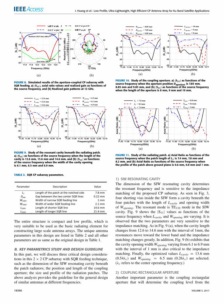
FIGURE 10. Study of the coupling aperture. a) |S11| as functions of thesource frequency when the aperture position Daperture is 7.85 mm,8.85 mm and 9.85 mm, and (b) |S11| as functions of the source frequencywhen the length of the aperture is 8 mm, 9 mm and 10 mm.
FIGURE 11. Study of the radiating patch. a) Axial Ratio as functions of thesource frequency when the patch length of L1 is 7.4 mm, 7.8 mm and8.2 mm, and (b) Axial Ratio as functions of the source frequency whenthe profile of the patch above ground plane is 0.6 mm, 0.8 mm and 1 mm.
1) SIW RESONATING CAVITYThe dimension of the SIW resonating cavity determinesthe resonant frequency and is sensitive to the impedancematching of the proposed CP subarray. As seen in Fig. 3,four shorting vias inside the SIW form a cavity beneath thefour patches with the length of Lcavity and opening widthof Wopening. The resonant mode is TE110 mode in the SIWcavity. Fig. 9 shows the |S11| values as functions of thesource frequency when Lcavity and Wopening are varying. It isobserved that the two parameters are very sensitive to theimpedance matching. As in Fig. 9 (a), when the cavity lengthchanges from 12.6 to 14.6 mm with the interval of 1mm, theresonances move toward the lower band and the impedancematching changes greatly. In addition, Fig. 9 (b) exhibits thatthe cavity opening widthWopening varying from 6.1 to 6.9 mmwith the interval of 1 mm is also critical to the impedancematching. Finally, the optimized values Lcavity = 13.6 mm(0.54λc) and Wopening = 6.5 mm (0.26λc) are selected.(λc refers to the center operating frequency.)
2) COUPLING RECTANGULAR APERTUREAnother important parameter is the coupling rectangularaperture that will determine the coupling level from the
18360 VOLUME 5, 2017

J. Huang et al.: Low Profile, Ultra-Lightweight, High Efficient CP Antenna Array for Ku Band Satellite Applications
FIGURE 12. Configuration of the compact, light weight and low profile 16× 6 CP patch array with SIW feedingnetwork. (a): Top view; and (b): Side view.
SIW cavity to the patch radiators. Both the position Dapertureand the length Laperture of the aperture will affect the couplinglevel as well as the impedance matching. Fig. 10 presentsthe returns loss values as Daperture and Laperture are vary-ing. It is seen that both parameters are sensitive to theimpedance matching. The optimized values Daperture =8.85 mm (0.35λc) and Laperture = 10 mm (0.4λc) are chosenfor the final design. Moreover, it is noted that the width of theaperture should be design as 1/50 of the length of the aperture.
3) RADIATING PATCHESThe dimension and profile of the radiating patches will deter-mine the axial ratio bandwidth of the CP subarray. It is well-known that the operating frequency of a square patch radiatoris determined by the length Lpatch and the CP performance isdependent on the length L1 on the side with the notch. In thefinal prototype, Lpatch is design as 0.45 λc. In addition,the profile Tfoam of the patches also affects the AR bandwidth.Fig. 11 presents the AR values as functions of the sourcefrequency when Lpatch and Tfoam are varying. Both the param-eters are sensitive to the AR bandwidth. The optimized valueL1 = 7.8 mm (0.7Lpatch) and Tfoam = 0.8 mm are selectedfor the final design.
4) DESIGN GUIDELINEThe design guideline for arbitrary frequency operation isconcluded as below:
The first step is to design the SIW feeding structure, whichwas thoroughly analyzed in [32] and [33]. The width of theSIWWSIW is set to 0.4λc in the initial design if the dielectricconstant of the substrate is 2.2 as the RogersTM 5880.
The second step is to determine the dimension of the cavitywith the coupling aperture. The length of the SIW cavityLcavity and the openingwidthWopening can be set to 0.54λc and0.26 λc, respectively in the initial design. Later, a rectangularaperture is etched on the top surface of the SIW with thedistance Laperture = 0.35 λc towards the end. The length ofthe aperture Laperture is set to the same as the width of theSIW WSIW .
The third step is to design the SQR feeding line andthe associated radiating patches. To match the impedanceof the coupling aperture, the characteristic impedance ofthe microstrip line section above the aperture is set to110 ohm (width is 1 mm). The microstrip line section to feedthe patch is set to 75 ohm (width is 2.1 mm), which matchesthe radiation impedance of the corner-notched patch. To pro-vide the 90◦ phase difference, the SQR line_2 is quarterwavelength longer than the SQR line_1 as seen in Fig. 6. SQRline_3 is identical to SQR line_1 and SQR line_4 is identicalto SQR line_2. Finally, the initial size of the patch Lpatch andL1 are set to 0.45 λc and 0.7Lpatch, respectively.
IV. IMPLEMENTATION AND MEASURED RESULTS OF THE96-ELEMENT (16 × 6) CP PATCH ARRAYBased on above CP subarray design, we successfullyexpanded it into a 96-element 16 × 6 array as shownin Fig. 12. 24 CP subarrays are arranged into three rows,which are fed by a 1 to 24 SIW feeding network. To pro-vide the balanced excitation for each subarray, both 1:1 and1:2 SIW power dividers are adopted. In addition, to providethe correct phase for the neighboring subarrays, out-of-phaseSIW power dividers are also used. The entire SIW feeding
VOLUME 5, 2017 18361

J. Huang et al.: Low Profile, Ultra-Lightweight, High Efficient CP Antenna Array for Ku Band Satellite Applications
TABLE 3. Design comparisons of the cp antenna arrays reported in the literature to date.
FIGURE 13. Fabricated antenna array model. a) Top view, and(b) Bottom view.
structure is very compact. The array components were fabri-cated and assembled as in Fig. 13. The radiating patches wereetched on a piece of Polyimide film. The 1 to 24 SIW feedingnetwork is fabricated on a block of RogersTM 5880 copper-cladded substrate by standard PCB manufacturing technol-ogy. A piece of sticky supporting foam was placed betweenthe film and the SIW substrate to provide the correct gapbetween the patches and the SIW surface. The rectangularareas of the foam beneath the patches were removed forfurther decreasing the total weight and loss of the array. Thefinal prototype achieved very low profile of 0.05λ0 and thetotal weight is only 66.5 gram. The overall size of the array is340 mm (13λ0) × 137 mm (5.3λ0). The |S11| of the antenna
FIGURE 14. Measured and simulated |S11| and directivity of fabricatedantenna array.
FIGURE 15. Measured and simulated Axial Ratio, gain and radiationefficiency.
was measured with a Keysight N5230C vector network ana-lyzer and the radiation patternwasmeasured by theNear-fieldantenna measurement system. All the simulated results wereobtained with the Ansoft HFSS EM solver version 17.
Measured and simulated |S11| and directivity are shownin Fig. 14, which are in reasonable agreement. The mea-sured −10 dB impedance bandwidth is 750 MHz from11.55 to 12.3 GHz. It slightly shifts to the lower band than the
18362 VOLUME 5, 2017

J. Huang et al.: Low Profile, Ultra-Lightweight, High Efficient CP Antenna Array for Ku Band Satellite Applications
FIGURE 16. Measured and simulated radiation patterns at 12 GHz.(a) ϕ = 0◦ plane. (b) ϕ = 90◦ plane.
simulation. Measured directivity is stable across theimpedance bandwidth with the peak value of 28.6 dBic.
Figure 15 presents the measured and simulated AR band-width, gain and radiation efficiency. In consistent with theimpedance bandwidth, the AR bandwidth slightly shifts tothe lower band that covers 850MHz from 11.4 to 12.25 GHz.Consequently, the overlapped impedance & AR bandwidth is700 MHz from 11.55 to 12.25 GHz. The measured realizedgain is stable cross the entire operating bandwidth with thepeak value of 26.4 dBic. The peak measured radiation effi-ciency is 65% which is decent for such large scale array. Thelosses are mainly due to the insertion loss of the 1 to 24 SIWpower divider and the copper loss of the radiating patches.The simulated and measured radiation patterns at 12 GHz arecompared in Fig. 16, both agree with each other very well.
The above measured results exhibit the excellent radiationperformance of the proposed CP antenna array. Importantly,it is very low profile (0.05 λ0), ultra-lightweight (66.5 gram),high efficient (65%) and low-cost & simple fabrica-tion. Table 3 compares various characteristics between thereported CP antenna arrays and our design. It is concludedthat our design achieves the lowest profile and very lightweight. The fabrication process is simple and low-cost. Therealized gain and efficiency are decent. It is an ideal candidatefor ku band mobile satellite applications.
V. CONCLUSIONA low-profile, ultra-lightweight and high efficient CP antennaarray is presented in the paper. Two designs of aperture-fed 2 × 2 patch subarrays were presented at the beginning.Based on the initial subarray with out of phase excitations,we designed a novel and compact sequential rotation (SQR)feeding technique to broaden the operating bandwidth formore than three times than the original design. Based onthe subarray as the basic radiating element, we expanded itinto a 96-element 16× 6 patch array. Measured results showexcellent CP radiation performance with decent bandwidth,realized gain and radiation pattern. Meanwhile, it is very low-profile, ultra-lightweight and high efficient. It is a good can-didate for wireless systems preferring high gain CP antennas,in particular, Ku band satellite communication applications.
REFERENCES[1] S.-I. Jeon, Y.-W. Kim, and D.-G. Oh, ‘‘A new active phased array
antenna for mobile direct broadcasting satellite reception,’’ IEEE Trans.Broadcast., vol. 46, no. 1, pp. 34–40, Mar. 2000.
[2] A. R. Weily and Y. J. Guo, ‘‘Circularly polarized ellipse-loaded circularslot array formillimeter-waveWPAN applications,’’ IEEE Trans. AntennasPropag., vol. 57, no. 10, pp. 2862–2870, Oct. 2009.
[3] W. Lin and H. Wong, ‘‘Circularly polarized conical-beam antenna withwide bandwidth and low profile,’’ IEEE Trans. Antennas Propag., vol. 62,no. 12, pp. 5974–5982, Dec. 2014.
[4] Q.-X. Chu, W. Lin, W.-X. Lin, and Z.-K. Pan, ‘‘Assembled dual-bandbroadband quadrifilar helix antennas with compact power divider networksfor CNSS application,’’ IEEE Trans. Antennas Propag., vol. 61, no. 2,pp. 516–523, Feb. 2013.
[5] M. T. Zhang et al., ‘‘Design of novel reconfigurable reflectarrays withsingle-bit phase resolution for Ku-band satellite antenna applications,’’IEEE Trans. Antennas Propag., vol. 64, no. 5, pp. 1634–1641, May 2016.
[6] S. Ye et al., ‘‘High-gain planar antenna arrays for mobile satellite commu-nications [antenna applications corner],’’ IEEE Antennas Propag. Mag.,vol. 54, no. 6, pp. 256–268, Dec. 2012.
[7] J. Huang et al., ‘‘A new compact and high gain circularly-polarized slotantenna array for Ku-band mobile satellite TV reception,’’ IEEE Access,vol. 5, pp. 6707–6714, May 2017.
[8] ‘‘Data sheet of the 65 cm Ku band offset dish antenna,’’ Fortec Star Inc.,Appl. Note. [Online]. Available: http://www.viasatelital.com
[9] H. Wong, W. Lin, L. Huitema, and E. Arnaud, ‘‘Multi-polarization recon-figurable antenna for wireless biomedical system,’’ IEEE Trans. Biomed.Circuits Syst., vol. 11, no. 3, pp. 652–660, Jun. 2017.
[10] W. Lin and H. Wong, ‘‘Wideband circular-polarization reconfigurableantenna with L-shaped feeding probes,’’ IEEE Antenna Wireless Propag.Lett., vol. 16, pp. 2114–2117, Apr. 2017, doi: 10.1109/LAWP.2017.2699289.
[11] W. Lin and H. Wong, ‘‘Multipolarization-reconfigurable circular patchantenna with L-shaped probes,’’ IEEE Antenna Wireless Propag. Lett.,vol. 16, pp. 1549–1552, 2017.
[12] C. Liu, Y.-X. Guo, X. Bao, and S.-Q. Xiao, ‘‘60-GHz LTCC integratedcircularly polarized helical antenna array,’’ IEEE Trans. Antennas Propag.,vol. 60, no. 3, pp. 1329–1335, Mar. 2012.
[13] Q. Zhu, K.-B. Ng, and C. H. Chan, ‘‘Printed circularly polarized spiralantenna array for millimeter-wave applications,’’ IEEE Trans. AntennasPropag., vol. 65, no. 2, pp. 636–643, Feb. 2017.
[14] Y. Li and K.-M. Luk, ‘‘A 60-GHz wideband circularly polarized aperture-coupled magneto-electric dipole antenna array,’’ IEEE Trans. AntennasPropag., vol. 64, no. 4, pp. 1325–1333, Apr. 2016.
[15] A. B. Guntupalli and K. Wu, ‘‘60-GHz circularly polarized antenna arraymade in low-cost fabrication process,’’ IEEE Antennas Wireless Propag.Lett., vol. 13, pp. 864–867, 2014.
[16] W. Zhang, Y. P. Zhang, M. Sun, C. Luxey, D. Titz, and F. Ferrero,‘‘A 60-GHz circularly-polarized array antenna-in-package in LTCC tech-nology,’’ IEEE Trans. Antennas Propag., vol. 61, no. 12, pp. 6228–6232,Dec. 2013.
VOLUME 5, 2017 18363

J. Huang et al.: Low Profile, Ultra-Lightweight, High Efficient CP Antenna Array for Ku Band Satellite Applications
[17] Y. Li, Z. N. Chen, X. Qing, Z. Zhang, J. Xu, and Z. Feng, ‘‘Axial ratiobandwidth enhancement of 60-GHz substrate integrated waveguide-fedcircularly polarized LTCC antenna array,’’ IEEE Trans. Antennas Propag.,vol. 60, no. 10, pp. 4619–4626, Oct. 2012.
[18] H. Sun, Y.-X. Guo, and Z. Wang, ‘‘60-GHz circularly polarized U-slotpatch antenna array on LTCC,’’ IEEE Trans. Antennas Propag., vol. 61,no. 1, pp. 430–435, Jan. 2013.
[19] J. Wu, Y. J. Cheng, and Y. Fan, ‘‘Millimeter-wave wideband high-efficiency circularly polarized planar array antenna,’’ IEEE Trans.Antennas Propag., vol. 64, no. 2, pp. 535–542, Feb. 2016.
[20] H. W. Lai, D. Xue, H. Wong, K. K. So, and X. Y. Zhang, ‘‘Broadbandcircularly polarized patch antenna arrays with multiple-layers structure,’’IEEE Antennas Wireless Propag. Lett., vol. 16, pp. 525–528, 2017.
[21] M. Li and K.-M. Luk, ‘‘Low-cost wideband microstrip antenna array for60-GHz applications,’’ IEEE Trans. Antennas Propag., vol. 62, no. 6,pp. 3012–3018, Jun. 2014.
[22] D.-F. Guan, C. Ding, Z.-P. Qian, Y.-S. Zhang, Y. J. Guo, andK. Gong, ‘‘Broadband high-gain SIW cavity-backed circular-polarizedarray antenna,’’ IEEE Trans. Antennas Propag., vol. 64, no. 4,pp. 1493–1497, Apr. 2016.
[23] Y. Lang, S.-W. Qu, and J.-X. Chen, ‘‘Wideband circularly polarized sub-strate integrated cavity-backed antenna array,’’ IEEE Antennas WirelessPropag. Lett., vol. 13, pp. 1513–1516, 2014.
[24] J. M. F. González, P. Padilla, G. Expósito-Domínguez, andM. Sierra-Castañer, ‘‘Lightweight portable planar slot array antennafor satellite communications in X-band,’’ IEEE Antennas WirelessPropag. Lett., vol. 10, pp. 1409–1412, 2011.
[25] Z. C. Hao, X. Liu, X. Huo, and K. K. Fan, ‘‘Planar high-gain circularlypolarized element antenna for array applications,’’ IEEE Trans. AntennasPropag., vol. 63, no. 5, pp. 1937–1948, May 2015.
[26] Y. J. Cheng, Y. X. Guo, and Z. G. Liu, ‘‘W-band large-scale high-gainplanar integrated antenna array,’’ IEEE Trans. Antennas Propag., vol. 62,no. 6, pp. 3370–3373, Jun. 2014.
[27] H. Wong, K.-M. Luk, C. H. Chan, Q. Xue, K. K. So, and H. W. Lai,‘‘Small antennas in wireless communications,’’Proc. IEEE, vol. 100, no. 7,pp. 2109–2121, Jul. 2012.
[28] A. Nešić, V. Branković, and I. Radnović, ‘‘Circularly polarisedprinted antenna with conical beam,’’ Electron. Lett., vol. 34, no. 12,pp. 1165–1167, Jun. 1998.
[29] B. Lee and Y. Yoon, ‘‘Low-profile, low-cost, broadband millimeter-waveantenna array for high-data-rateWPAN systems,’’ IEEE AntennasWirelessPropag. Lett., vol. 16, pp. 1957–1960, Apr. 2017, doi: 10.1109/LAWP.2017.2690440.
[30] W. Lin and H. Wong, ‘‘Wideband circular polarization reconfigurableantenna,’’ IEEE Trans. Antennas Propag., vol. 63, no. 12, pp. 5938–5944,Dec. 2015.
[31] Q. Wu, H. Wang, C. Yu, and W. Hong, ‘‘Low-profile circularly polarizedcavity-backed antennas using SIW techniques,’’ IEEE Trans. AntennasPropag., vol. 64, no. 7, pp. 2832–2839, Jul. 2016.
[32] L. Yan, W. Hong, G. Hua, J. Chen, K. Wu, and T. J. Cui, ‘‘Simulation andexperiment on SIW slot array antennas,’’ IEEE Microw. Wireless Compon.Lett., vol. 14, no. 9, pp. 446–448, Sep. 2004.
[33] D. Deslandes and K. Wu, ‘‘Accurate modeling, wave mechanisms, anddesign considerations of a substrate integrated waveguide,’’ IEEE Trans.Microw. Theory Techn., vol. 54, no. 6, pp. 2516–2526, Jun. 2006.
JIANQUAN HUANG received the M.S. degreefrom Hunan Normal University, Changsha,Hunan, and the Ph.D. degree from the South ChinaUniversity of Technology, Guangzhou, China.Since 2012, he has been an Associate Profes-sor with Xiangnan University, Chenzhou, China,where he is also currently charging the MicrowaveCommunication Joint Laboratory. He is alsocharging Gospell. He is currently visiting theGlobal Big Data Technologies Centre, University
of Technology Sydney, Australia.His research interests are mainly in the fields of circularly polarized planar
antenna and array and reconfigurable planar antenna.
WEI LIN (M’16) received the bachelor’s andmaster’s degrees in electronic engineering fromthe South China University of Technology,Guangzhou, China, in 2009 and 2012, respec-tively, and the Ph.D. degree in electronic engi-neering from the City University of Hong Kong,Hong Kong, in 2016. He was a Research Asso-ciate with Nanyang Technological University,Singapore, from 2012 to 2013.
He is currently a Post-Doctoral Research Fellowwith the Global Big Data Technologies Centre, University of TechnologySydney, Sydney, Australia. He received the Outstanding Master ThesisAward from the South China University of Technology in 2013, the YoungScientist Award at the IEEE Region 10 Conference in 2015, and the TalentDevelopment Scholarship from the Hong Kong SAR Government in 2016.His research interests include designs of reconfigurable antennas, HF anten-nas, satellite antennas, millimeter wave antennas, and terahertz devices andapplications.
FENG QIU received the B.S and M.S degreesin electrical and information engineering fromXidian University, Xi’an, in 2012 and 2015,respectively. Since 2015, he has been a Lecturerwith Xiangnan University, Chenzhou, China. Hisresearch interests are predominantly in the fieldof microwave components using dielectric res-onators and circularly polarized planar antennasand antenna arrays.
CHUNZHI JIANG received the M.S. degreefrom the National University of Defense Tech-nology, Changsha, China. She has been a Pro-fessor with the School of Electronic Informationand Electrical Engineering, Xiangnan University,Chenzhou, since 2014. Her research interests aremainly in the fields of electromagnetic field theoryand applications.
18364 VOLUME 5, 2017

J. Huang et al.: Low Profile, Ultra-Lightweight, High Efficient CP Antenna Array for Ku Band Satellite Applications
DAJUN LEI received the B.S. degree fromHunan Normal University in 1996 and the Ph.D.degree from Hunan University, Changsha, China,in 2011.
He is currently a Professor with the School ofElectronic Information and Electrical Engineer-ing, Xiangnan University, Chenzhou. His researchinterests are mainly in the fields of dielectric res-onator microwave components and planar anten-nas and arrays.
Y. JAY GUO (F’14) received the bachelor’s andmaster’s degrees from Xidian University, China,in 1982 and 1984, respectively, and the Ph.D.degree from Xian Jiaotong University, China,in 1987. He has authored over 300 research papers,and he holds 22 patents in antennas and wirelesssystems. His research interest includes antennas,mm-wave and THz communications, sensing sys-tems, as well as big data. He is a fellow of theAustralian Academy of Engineering and Technol-
ogy and the IET, and a member of the College of Experts of AustralianResearch Council. He has received a number of most prestigious Australiannational awards, and was named one of the most influential engineers inAustralia in 2014 and 2015.
In 2014, he served as a Director of CSIRO for over nine years, directinga number of ICT research portfolios. Before joining CSIRO, he held varioussenior leadership positions at Fujitsu, U.K., Siemens, U.K., and NEC, U.K.He is currently a Distinguished Professor and the founding Director of theGlobal Big Data Technologies Centre, University of Technology Sydney,Australia.
Prof Guo has chaired numerous international conferences. He was theInternational Advisory Committee Chair of the IEEE VTC2017, the GeneralChair of ISAP2015, iWAT2014, and WPMC’2014, and the TPC Chairof 2010 IEEE WCNC, and 2012 and 2007 IEEE ISCIT. He served asthe Guest Editor of special issues on Antennas for Satellite Commu-nications and Antennas and Propagation Aspects of 60–90 GHz Wire-less Communications, both in the IEEE TRANSACTIONS ON ANTENNAS AND
PROPAGATION, special issue on Communications Challenges and Dynamicsfor Unmanned Autonomous Vehicles, the IEEE JOURNAL ON SELECTED AREAS
IN COMMUNICATIONS, and Special Issue on 5G for Mission Critical MachineCommunications, the IEEE Network Magazine.
VOLUME 5, 2017 18365