digital multimeter voac752xh instruction manual · digital multimeter voac7520h voac7521h ......
TRANSCRIPT

Instruction Manual
Digital Multimeter
VOAC7520H VOAC7521H VOAC7522H VOAC7523H

2010_2013 IWATSU TEST INSTRUMENTS CORPORATION.All rights reserved.
I
Introduction Thank you for purchasing this product. We appreciate your continued patronage of IWATSU
measuring instruments. Please read this manual carefully before using the instrument, and keep it handy for future
reference. This operation manual describes handling precautions, operating procedures, operating
examples, performance, and remote control by RS-232, GP-IB and Ethernet. This manual targets the product of VOAC7520H / VOAC7521H / VOAC7522H /
VOAC7523H. Please refer to the manual of the product for VOAC7520/VOAC7521A/
VOAC7522/VOAC7523.
Safety Precautions To ensure safe operation of this instrument and to prevent personal injury or damage to property, read and carefully observe the warnings and cautions in the following section and associated symbols marked on the panels.
Definitions of warnings and cautions used in this manual
WARNING Incorrect operation or failure to observe warnings may result in death or serious injury.
CAUTION Incorrect operation or failure to observe cautions may result in injury or damage to the instrument.
Definitions of panel symbols
General warning To protect the body and to prevent damage to this instrument, refer to the items described in this manual prior to operation.
Electric shock This symbol calls attention to protecting the body from high voltages, and indicates that voltages over 1 kV are supplied to the terminals from the inside or outside of the device.
Precautions Parts of the contents of this manual may be changed without notice following improvements in
performance and function. Reproduction or reprinting of the contents of this manual without prior permission from Iwatsu
is prohibited. Since the display panel of this product contains a fluorescent tube, when discarding it, be sure
to comply with the appropriate dumping regulations. Microsoft & MS-DOS are trademarks of Microsoft Corporation in the U.S. Windows is registered trademark of Microsoft Corporation in the U.S. and/or other countries. The names of actual companies and products mentioned herein may be the trademarks of their
respective owners. For questions about this product, contact IWATSU TEST INSTRUMENTS CORPORATION
listed at the end of this manual or our sales distributors.
Revision History February 2010 : 1st edition January 2011 : 2nd edition May 2011 : 3rd edition October 2013 : 4th edition
KML070541 A3747-521250(N)

II
Read the following pages to ensure safety. Read the next page also.
Warnings
Do not use in a location with explosive gases in the vicinity. This may result in an explosion.
In the event of smoke, abnormal odors or abnormal sounds, immediately turn the power off and unplug the power cord. Continued use under these circumstances may result in electric shock or fire. Turn off the power, disconnect the plug and contact an Iwatsu service location (see “Service Network listed at the end of this manual or our sales distributors”) for repairs. Repairing the product yourself is dangerous, so do not attempt to do so under any circumstances.
Ensure that water does not get on or inside the product. Do not use the product if this happens. Failure to observe this precaution may result in electric shock or fire. If water gets on or inside the unit, immediately turn off the power, unplug the power cord and contact an Iwatsu service location (see “Service Network listed at the end of this manual or our sales distributors”) for repairs.
Do not touch the power cord plug with wet hands This may result in an electric shock.
Do not place this instrument in an unstable location such as on an unsteady stand or an inclined place. If the instrument is placed in an unstable location, it may fall or topple over, resulting in electric shock, fire or injury. If this instrument falls or its cover is damaged, turn off the power, unplug the power cord and contact an Iwatsu service location (see “Service Network listed at the end of this manual or our sales distributors”) for repairs.
Do not remove the cover or panels. The product contains high-voltage components, which if touched, may result in electric shock. Contact an Iwatsu service location (see “Service Network listed at the end of this manual or our sales distributors”) when carrying out inspections, calibrations or repairs.
Be careful when taking high-voltage measurements. Coming into contact with high voltages during measurements may result in electric shock.
Always use a 3-prong power cord
Failing to use a 3-prong power cord may result in electric shock or malfunction. ・When supplying power via a two-wire power outlet using a 3-prong to 2-prong conversion adapter, be sure to ground the adapter’s earth terminal. ・When supplying power via a three-wire power outlet using the 3-prong power cord accessory, ground the cord using the ground wire.
III
Read the following pages to ensure safety. Read the next page also.
Warnings (Continued)
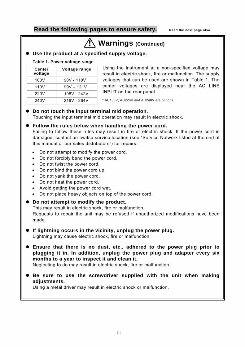
Use the product at a specified supply voltage.
Using the instrument at a non-specified voltage may result in electric shock, fire or malfunction. The supply voltages that can be used are shown in Table 1. The center voltages are displayed near the AC LINE INPUT on the rear panel.
* AC100V, AC220V and AC240V are options.
Do not touch the input terminal mid operation. Touching the input terminal mid operation may result in electric shock.
Follow the rules below when handling the power cord. Failing to follow these rules may result in fire or electric shock. If the power cord is
damaged, contact an Iwatsu service location (see “Service Network listed at the end of this manual or our sales distributors”) for repairs.
• Do not attempt to modify the power cord. • Do not forcibly bend the power cord. • Do not twist the power cord. • Do not bind the power cord up. • Do not yank the power cord. • Do not heat the power cord. • Avoid getting the power cord wet. • Do not place heavy objects on top of the power cord.
Do not attempt to modify the product. This may result in electric shock, fire or malfunction.
Requests to repair the unit may be refused if unauthorized modifications have been made.
If lightning occurs in the vicinity, unplug the power plug. Lightning may cause electric shock, fire or malfunction.
Ensure that there is no dust, etc., adhered to the power plug prior to plugging it in. In addition, unplug the power plug and adapter every six months to a year to inspect it and clean it.
Neglecting to do may result in electric shock, fire or malfunction.
Be sure to use the screwdriver supplied with the unit when making adjustments.
Using a metal driver may result in electric shock or malfunction.
Table 1. Power voltage range
Center voltage
Voltage range
100V 90V - 110V 110V 99V – 121V 220V 198V - 242V 240V 216V - 264V
IV
Read the following pages to ensure safety. Read the next page also.
Cautions Always use a 3-core power cord compatible with the power voltage.
Using a power cord that is incompatible with the power voltage may result in fire. Additionally, using a 2-prong power cord may result in electric shock.
Unless otherwise specified at purchase, a 100V* power cord is supplied with the product. If operating the instrument at 200V**, always use the 3-prong power cord (optional) for 200V systems (rating: 250V) specified by Iwatsu.
*Center voltage of 100V or 110V (see Table 1 on page III) **Center voltage of 220V or 240V (see Table 1 on page III)
When voltage is being applied to the LO terminal, do not connect it to the ground terminal of another measuring device. The LO terminal is not grounded, and is just floating. If voltage is being applied to the LO terminal, connecting it to the ground terminal of another measuring device may result in fire or damage.
Do not apply a voltage between the LO terminal and the ground exceeding the specified voltage. The specified voltage is ±500V DC. Applying voltages exceeding this may cause fire or damage.
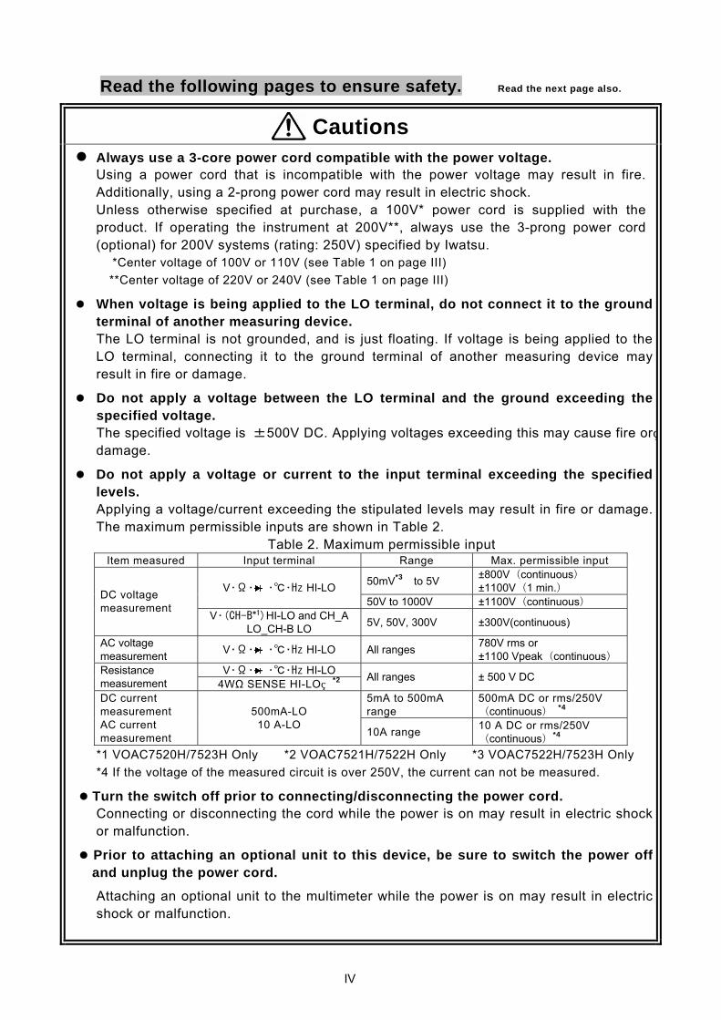
Do not apply a voltage or current to the input terminal exceeding the specified levels. Applying a voltage/current exceeding the stipulated levels may result in fire or damage. The maximum permissible inputs are shown in Table 2.
Table 2. Maximum permissible input Item measured Input terminal Range Max. permissible input
50mV*3 to 5V ±800V(continuous) ±1100V(1 min.) V・Ω・ ・・Hz HI-LO
50V to 1000V ±1100V(continuous) DC voltage measurement
V・(CH-B*1)HI-LO and CH_A LO_CH-B LO 5V, 50V, 300V ±300V(continuous)
AC voltage measurement V・Ω・ ・・Hz HI-LO All ranges 780V rms or
±1100 Vpeak(continuous)V・Ω・ ・・Hz HI-LO Resistance
measurement 4WΩ SENSE HI-LO *2 All ranges ± 500 V DC
5mA to 500mA range
500mA DC or rms/250V (continuous)
*4 DC current measurement AC current measurement
500mA-LO 10 A-LO
10A range 10 A DC or rms/250V (continuous)*4
*1 VOAC7520H/7523H Only *2 VOAC7521H/7522H Only *3 VOAC7522H/7523H Only *4 If the voltage of the measured circuit is over 250V, the current can not be measured.
Turn the switch off prior to connecting/disconnecting the power cord. Connecting or disconnecting the cord while the power is on may result in electric shockor malfunction.
Prior to attaching an optional unit to this device, be sure to switch the power off and unplug the power cord.
Attaching an optional unit to the multimeter while the power is on may result in electric shock or malfunction.
V
Read the following pages to ensure safety.
Cautions (Continued)
When unplugging the power cord, pull on the plug itself. Pulling the power cord may result in damage, electric shock or fire.
When connecting cables to the multimeter, pull them carefully so as to avoid toppling the multimeter. Toppling the multimeter may result in electric shock, injury or fire.
Do not use damaged cables or adapter. Using damaged cables or adapter may result in electric shock or fire.
The tip of the measuring lead is sharp to facilitate measurements. Be careful not to inadvertently prick your finger, etc.
Do not use the multimeter if it is damaged. Using the multimeter when damaged may result in electric shock or fire. If damaged, contact an Iwatsu service location (see “Service Network listed at the end of this manual or our sales distributors”) for repairs.
Do not place the multimeter in a location with excessive humidity or dust. Doing so may result in electric shock, fire or malfunction.
Do not stack anything on top of the multimeter. Doing so will cause the cover to come into contact with the internal circuitry, which may result in electric shock, fire or malfunction.
Use the multimeter only within the specified operating ranges. Using the multimeter outside of the operating ranges may cause malfunction. The permissible humidity and temperature ranges are as follows. Temperature: 0°C to +50°C Humidity: Max. 80% RH (0°C to +40°C) Max. 70% RH(+40°C to+50°C)
If the multimeter remains unused for a long period, unplug the power cord for safety’s sake.
When transporting the multimeter, use the original packing materials or comparable materials. Excessive vibration or shock applied to the multimeter during transportation may cause it to malfunction, resulting in fire. If you do not have appropriate packing materials or padding, contact an Iwatsu service location (see “Service Network listed at the end of this manual or our sales distributors”) for advice. When having the unit transported by a shipping company, write "Precision Instrument - Handle With Care" on each side of the packing box.
VI
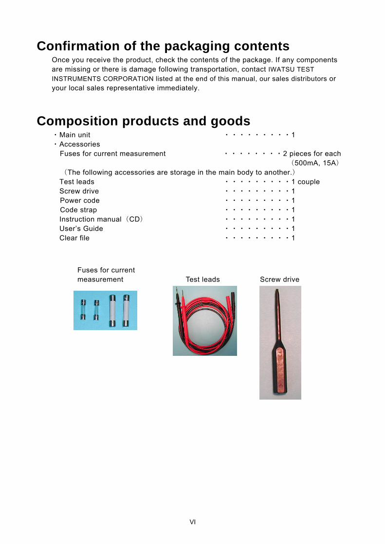
Confirmation of the packaging contents Once you receive the product, check the contents of the package. If any components are missing or there is damage following transportation, contact IWATSU TEST INSTRUMENTS CORPORATION listed at the end of this manual, our sales distributors or your local sales representative immediately.
Composition products and goods ・Main unit ・・・・・・・・・1 ・Accessories
Fuses for current measurement ・・・・・・・・2 pieces for each
(500mA, 15A) (The following accessories are storage in the main body to another.) Test leads ・・・・・・・・・1 couple Screw drive ・・・・・・・・・1
Power code ・・・・・・・・・1 Code strap ・・・・・・・・・1
Instruction manual(CD) ・・・・・・・・・1 User’s Guide ・・・・・・・・・1 Clear file ・・・・・・・・・1
Test leads Screw drive Fuses for current measurement
VII
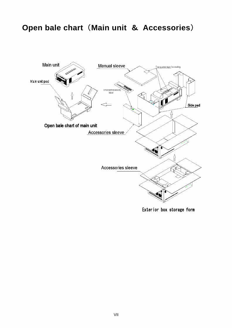
Open bale chart(Main unit & Accessories)

VIII
Management of products When this product is abandoned, it is necessary to recycle or to abandon it appropriately according to the law in the region and the rule.
Repair and return of repair goods Please send it back to our service handling place when the breakdown occurs by any chance. Sorry to trouble you, but please describe the name, belonging, and the telephone number etc. of the product name, the serial number (The label is pasted to the back of this product), and a defective content and the person in charge clearly before sending back the repair goods.
IX
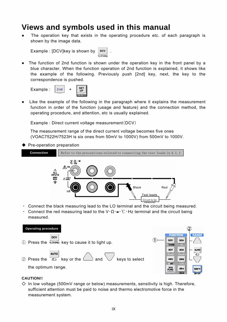
Views and symbols used in this manual The operation key that exists in the operating procedure etc. of each paragraph is
shown by the image data.
Example : [DCV]key is shown by .
The function of 2nd function is shown under the operation key in the front panel by a blue character. When the function operation of 2nd function is explained, it shows like the example of the following. Previously push [2nd] key, next, the key to the correspondence is pushed.
Example : +
Like the example of the following in the paragraph where it explains the measurement function in order of the function (usage and feature) and the connection method, the operating procedure, and attention, etc is usually explained.
Example : Direct current voltage measurement(DCV)
The measurement range of the direct current voltage becomes five ones (VOAC7522H/7523H is six ones from 50mV to 1000V) from 500mV to 1000V.
Pre-operation preparation
・ Connect the black measuring lead to the LO terminal and the circuit being measured. ・ Connect the red measuring lead to the V・Ω・ ・・Hz terminal and the circuit being
measured.
① Press the key to cause it to light up.
② Press the key or the and keys to select
the optimum range. CAUTION!! In low voltage (500mV range or below) measurements, sensitivity is high. Therefore,
sufficient attention must be paid to noise and thermo electromotive force in the measurement system.
Operating procedure
Refer to the precautions related to connecting the test leads in 4.1.1 Connection h d
Test leadsCircuit to be
measured
Black Red

X
Memo
Instruction Manual

0-1
Contents
Introduction.............................................................................................................................................Ⅰ Safety Precautions .................................................................................................................................Ⅰ Warnings.................................................................................................................................................Ⅱ Cautions..................................................................................................................................................Ⅳ
Confirmation of the packaging contents .................................................................................................Ⅵ Composition products and goods...........................................................................................................Ⅵ Open bale chart(Main unit & Accessories) .......................................................................................Ⅶ Management of products........................................................................................................................Ⅷ Repair and return of repair goods ..........................................................................................................Ⅷ Views and symbols used in this manual.................................................................................................Ⅸ
Chapter 1 Overview
1.1 Features ...................................................................................................................................... 1-2
1.2 Comparison of functions between series .................................................................................... 1-2
1.3 Options and accessories ............................................................................................................. 1-3
Chapter 2 Basic Operation
2.1 Operating precautions ................................................................................................................. 2-2
2.1.1 Prior to use......................................................................................................................... 2-2
2.2 Turning the power on and completing measurements................................................................ 2-3
2.3 Panel description and key operations ......................................................................................... 2-4
2.3.1 Front panel (VOAC7521H/7522H) ..................................................................................... 2-4
2.3.2 Front panel (VOAC7520H/7523H) ..................................................................................... 2-9
2.3.3 Rear panel (VOAC7520H/VOAC7521H/VOAC7522H/VOAC7523H) ............................. 2-10
2.3.4 Operating modes and key operations .............................................................................. 2-11
2.4 Display....................................................................................................................................... 2-13
2.4.1 SINGLE/DUAL display ..................................................................................................... 2-13
2.4.2 Display selection .............................................................................................................. 2-13
Chapter 3 Operating Principles
3.1 Input signal converter .................................................................................................................. 3-2
3.2 Principles of A/D conversion ....................................................................................................... 3-3
Chapter 4 Measurement Methods 4.1 Prior to taking measurements ..................................................................................................... 4-2
4.1.1 Precautions when connecting test leads............................................................................ 4-2
4.2 Measurement functions (FUNCTION)......................................................................................... 4-3
4.2.1 DC voltage measurement (DCV) ....................................................................................... 4-3
0-2
4.2.2 AC Voltage measurements (ACV) and (DC+AC) Voltage measurements (DC+AC)V...... 4-5
4.2.3 DC current measurements (DCA)...................................................................................... 4-7
4.2.4 AC current measurements (ACA) and (DC+AC) current measurements ((DC+AC)A) ..... 4-8
4.2.5 Resistance measurements............................................................................................... 4-10
4.2.6 Temperature measurements (°C) & thermocouple type configuration (TYPE) ............... 4-14
4.2.7 Frequency measurements (Hz) ....................................................................................... 4-16
4.2.8 Selecting a diode measurement and measurement current (If) ...................................... 4-17
4.2.9 dB measurements ............................................................................................................ 4-19
4.2.10 DC voltage measurement (CH-B DCV, VOAC7520H/7523H only) ................................. 4-21
4.3 Dual FUNCTION ....................................................................................................................... 4-22
4.3.1 Dual FUNCTION operation.............................................................................................. 4-23
4.3.2 Dual FUNCTION combinations ....................................................................................... 4-24
4.3.3 Dual function selection menu .......................................................................................... 4-27
4.3.4 Performing calculations using the main and sub Dual FUNCTION................................. 4-28
4.4 Displayed Information................................................................................................................ 4-29
4.4.1 Information displayed during Single FUNCTION measurement....................................... 4-30
4.4.2 Attribute information displayed during Single FUNCTION measurement ........................ 4-31
4.4.3 Information displayed during Dual FUNCTION measurement ......................................... 4-32
4.4.4 Exceptions displayed for measured values ...................................................................... 4-33
4.5 Setting and changing sampling (SAMPLE) ............................................................................... 4-34
4.5.1 Setting the sample rate (RATE)........................................................................................ 4-34
4.5.2 Setting the measurement interval (INT)............................................................................ 4-34
4.5.3 Switching between free run and hold (HOLD/TRIG and RES) ......................................... 4-35
4.6 Calculation functions (UTILITY) ................................................................................................ 4-36
4.6.1 Processing flow................................................................................................................. 4-36
4.6.2 Table of utility parameters................................................................................................. 4-37
4.6.3 Continuity tests ................................................................................................................. 4-40
4.6.4 Moving average calculation (AVG) ................................................................................... 4-42
4.6.5 Scaling calculation (SCLE) ............................................................................................... 4-44
4.6.6 Decibel calculations .......................................................................................................... 4-46
4.6.7 Relative value calculation (REL)....................................................................................... 4-48
4.6.8 Comparator calculation (COMP)....................................................................................... 4-50
4.6.9 Statistical calculations (MAX/MIN).................................................................................... 4-53
4.7 Saving and recalling setup (SETUP)......................................................................................... 4-56
4.8 Saving and recalling measurement data (SAVE/RECALL)....................................................... 4-59
4.8.1 Saving measurement data (SAVE)................................................................................... 4-59
4.8.2 Save formats for measurement data ................................................................................ 4-61
4.8.3 Recalling measurement data (RECALL)........................................................................... 4-61
0-3
4.9 Time stamp................................................................................................................................ 4-76
4.10 System setup (SYSTEM menu) ............................................................................................... 4-77
4.10.1 Setup at power on............................................................................................................. 4-78
4.10.2 Setting up energy saving mode ........................................................................................ 4-78
4.10.3 Setting up remote control interface................................................................................... 4-78
4.10.4 Setting up RS-232 communication ................................................................................... 4-78
4.10.5 Setting up GPIB communication....................................................................................... 4-79
4.10.6 Setting up Ethernet communication.................................................................................. 4-79
4.10.7 Setting up beep activation conditions ............................................................................... 4-79
4.10.8 Setting up output conditions for comparator calculations ................................................. 4-80
4.10.9 Setting up the data SAVE function ................................................................................... 4-80
4.10.10 Function for protecting resistance measuring circuit and AUTO range settings.......... 4-81
4.10.11 Setting AUTO range in voltage measurements ............................................................... 4-82
4.10.12 Setting the frequency of AC filter ..................................................................................... 4-83
4.10.13 Initializing the time stamp................................................................................................ 4-83
4.10.14 Setting up external triggers ............................................................................................. 4-83
4.11 Application measurements ........................................................................................................ 4-84
4.11.1 True RMS (root mean square) measurements ................................................................. 4-84
4.11.2 Examples of (DC +AC) signal measurements .................................................................. 4-85
Chapter 5 Performance Examination and Calibration 5.1 Overview...................................................................................................................................... 5-2
5.1.1 Period for examination and calibration............................................................................... 5-2
5.1.2 Reminders before carrying out examination and calibration.............................................. 5-2
5.1.3 Equipment required for calibration ..................................................................................... 5-3
5.1.4 Calibration items and basic calibration procedures ........................................................... 5-4
5.2 Adjustment .................................................................................................................................. 5-5
5.2.1 Heat run ............................................................................................................................. 5-5
5.2.2 Transition to adjustment mode........................................................................................... 5-5
5.2.3 DC voltage measurement (DCV) ....................................................................................... 5-8
5.2.4 CH-B DC voltage measurement (VOAC7520H/7523H only)........................................... 5-10
5.2.5 AC voltage measurement (ACV)...................................................................................... 5-12
5.2.6 Resistance measurement (Ohms) ................................................................................... 5-18
5.2.7 Direct current measurement (DCA) ................................................................................. 5-22
5.2.8 AC current measurement (ACA) ...................................................................................... 5-24
5.2.9 Temperature measurement (TEMP) ................................................................................ 5-26
5.2.10 Frequency measurement (Hz) ......................................................................................... 5-28
5.3 Changing fuses ......................................................................................................................... 5-29
0-4
Chapter 6 Specifications 6.1 Common specifications ............................................................................................................... 6-2
6.2 Basic measurement functions ..................................................................................................... 6-2
6.2.1 DC voltage DCV ................................................................................................................. 6-2
6.2.2 DC voltage CH-B DCV (equipped with only VOAC7520H/7523H) .................................... 6-3
6.2.3 AC voltage ACV, (DC+AC)V .............................................................................................. 6-3
6.2.4 DC current DCA ................................................................................................................. 6-4
6.2.5 AC current ACA, (DC+AC)A .............................................................................................. 6-5
6.2.6 Resistance 2WΩ/4WΩ (Resistance 4WΩ is only available on the VOAC7521H/7522H) . 6-6
6.2.7 Resistance Low-power 2WΩ .............................................................................................. 6-6
6.2.8 Diode test ........................................................................................................................ 6-7
6.2.9 Temperature °C .................................................................................................................. 6-7
6.2.10 Frequency measurement FREQ ........................................................................................ 6-8
6.3 General functions ........................................................................................................................ 6-8
6.4 Common functions ...................................................................................................................... 6-8
6.5 Optional interface ........................................................................................................................ 6-8
6.6 Optional accessories(Refer to section 7.4 for details) ................................................................ 6-9
6.7 Environmental conditions ............................................................................................................ 6-9
6.8 Accessories ................................................................................................................................. 6-9
6.9 Expected operating life ................................................................................................................ 6-9
6.10 Exterior/construction .................................................................................................................. 6-10
Chapter 7 Options and Accessories
7.1 Options ........................................................................................................................................ 7-2
7.1.1 Connection ......................................................................................................................... 7-2
7.1.2 Operation ........................................................................................................................... 7-2
7.2 Control using digital I/O (SC-352) ............................................................................................... 7-3
7.2.1 Functions ............................................................................................................................ 7-3
7.2.2 Attaching and removing option units .................................................................................. 7-3
7.2.3 Connection ......................................................................................................................... 7-4
7.2.4 Specifications of input and output terminals ...................................................................... 7-4
7.2.5 Main unit trigger configuration ............................................................................................ 7-4
7.2.6 Timing operation ................................................................................................................ 7-5
7.2.7 Output of results of compare calculations (/Hi, /Go, /Lo) ................................................... 7-5
7.3 D/A converter SC-354 (Optional) ................................................................................................ 7-8
7.3.1 Overview ............................................................................................................................ 7-8
7.3.2 Attaching/Detaching the option unit ................................................................................... 7-8
7.3.3 Specifications ..................................................................................................................... 7-9
7.3.4 Operation procedure .......................................................................................................... 7-9
0-5
7.3.5 Details of D/A converter output ........................................................................................ 7-10
7.3.6 LED Indicators.................................................................................................................. 7-13
7.4 Accessories ............................................................................................................................... 7-14

0-6
Memo
Overview
1-1
1234567
Chapter 1 Overview
Overview
1-2
1.1 Features
Simple operation The VOAC7520 / VOAC7521A / VOAC7522H / VOAC7523H are 5-1/2 digit multimeters.
Frequently used operations can easily be performed by one-touch operation.
Logging function The long interval measuring function and timestamp function make monitoring over a long interval possible.
Measurement data is stored internally, and can be read by the multimeter itself or an external PC.
Various calculation functions Solutions such as standard deviation, screening and monitoring of data following unit conversion (V to A etc.)
by scaling, statistics and comparator calculation functions can only be rendered by the main unit.
An external alarm (LED or lamp) can be driven by the comparator results by attaching a DIO board.
Ethernet interface An Ethernet environment enables a long-range distributed system to be created – something not possible with
GP-IB. GP-IB SC-303A compatible mode The multimeter has an SC-303A compatible mode that makes use of the GP-IB program used in previous
models, making them easily replaceable.
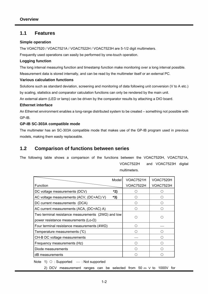
1.2 Comparison of functions between series
The following table shows a comparison of the functions between the VOAC7520H, VOAC7521A,
VOAC7522H and VOAC7523H digital
multimeters.
ModelFunction
VOAC7521H
VOAC7522H
VOAC7520HVOAC7523H
DC voltage measurements (DCV) *2)
AC voltage measurements (ACV, (DC+AC) V) *3)
DC current measurements (DCA)
AC current measurements (ACA, (DC+AC) A)
Two terminal resistance measurements (2WΩ) and low power resistance measurements (Lo-Ω)
Four terminal resistance measurements (4WΩ) ⎯
Temperature measurements ()
CH-B DC voltage measurements ⎯
Frequency measurements (Hz)
Diode measurements
dB measurements
Note 1) : Supported ⎯ : Not supported
2) DCV measurement ranges can be selected from 50 m V to 1000V for

Overview
1-3
VOAC7522H/7523H and from 500mVto 1000 V for VOAC7520H/7521H.
3) ACV measurement is ensured under the limits of 300 kHz for VOAC7522H/7523H,
and under the limits of 100 kHz for VOAC7520H/7521H.
1.3 Options and accessories (Details will be explained in Chapter 7)
Options Ethernet unit SC-351 (mountable in SLOT A)
Digital I/O unit SC-352 (mountable in SLOT B)
GP-IB unit SC-353 (mountable in SLOT A)
D/A converter unit SC-354 (mountable in SLOT B)
Accessories SC-004 Shielded cable for high-resistances of 100MΩ or less
SC-0107 Sheathed thermocouple (Type-K)
SC-0116 Static surface thermocouple (Type-K)
SC-020 Test leads (replacement for standard accessory, 1 red and 1black
lead per set)
SC-023 Alligator clips (H) for use with SC-020
SC-026 Arrow-shaped clips (SC-020 exclusive use)
SC-028 DC180A, AC130A, Current clamp probe
SC-525 USB-RS convertor
Instruction manual (CD)
User’s Guide (Printed matter)

Overview
1-4
Memo

Basic Operation
2-1
1234567
Chapter 2 Basic Operation
Basic Operation
2-2
2.1 Operating precautions
2.1.1 Prior to use Prior to using this product, confirm the following items:
Operate the multimeter within the specified operating range. Operating the multimeter outside the specified range may cause it to malfunction. The permissible temperature and humidity ranges are as follows. Indoor use only: Temperature:0°C to +50°C (condensation not permitted) Humidity: Max. 80% RH (0°C to +40°C); max. 70% RH in 40°C to 50°C range
Do not place the multimeter in a location with excessive humidity or dust. Doing so may result in electric shock, fire or malfunction.
Do not stack anything on top of the multimeter. Doing so may cause the cover to come into contact with the internal circuitry, which may result in electric shock, fire or malfunction.
Do not place objects near the vents. Doing so will trap heat inside the multimeter, which may result in fire or malfunction.
Maintain space around the rear and sides of the multimeter. When placing the multimeter in a rack mount or on top of other measuring devices, be careful of a rise in temperature. This may adversely affect operability and function. For further information, contact IWATSU TEST INSTRUMENTS CORPORATION listed at the end of this manual or our sales distributors.
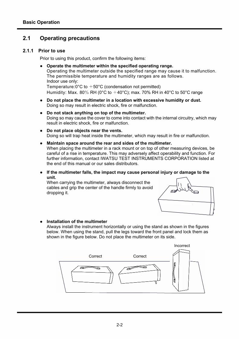
If the multimeter falls, the impact may cause personal injury or damage to the unit. When carrying the multimeter, always disconnect the cables and grip the center of the handle firmly to avoid dropping it.
Installation of the multimeter
Always install the instrument horizontally or using the stand as shown in the figures below. When using the stand, pull the legs toward the front panel and lock them as shown in the figure below. Do not place the multimeter on its side.
Correct Correct
Incorrect
Basic Operation
2-3
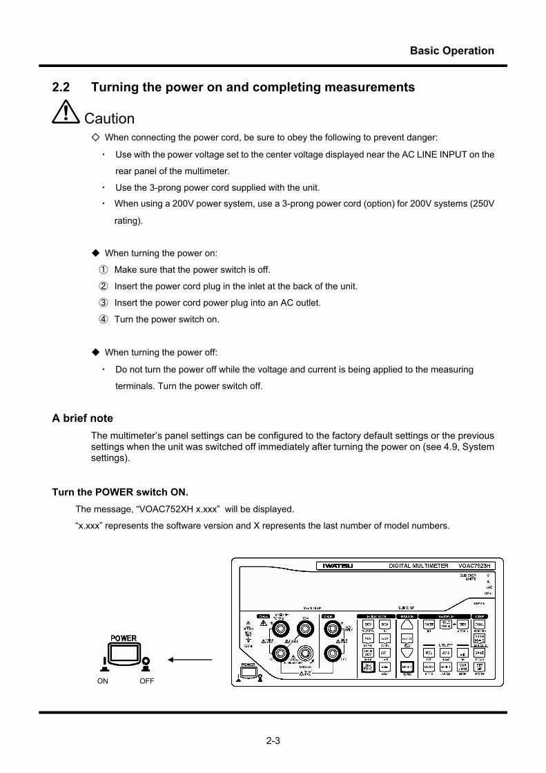
2.2 Turning the power on and completing measurements
Caution When connecting the power cord, be sure to obey the following to prevent danger:
・ Use with the power voltage set to the center voltage displayed near the AC LINE INPUT on the
rear panel of the multimeter.
・ Use the 3-prong power cord supplied with the unit.
・ When using a 200V power system, use a 3-prong power cord (option) for 200V systems (250V
rating).
When turning the power on:
① Make sure that the power switch is off.
② Insert the power cord plug in the inlet at the back of the unit.
③ Insert the power cord power plug into an AC outlet.
④ Turn the power switch on.
When turning the power off:
・ Do not turn the power off while the voltage and current is being applied to the measuring
terminals. Turn the power switch off.
A brief note The multimeter’s panel settings can be configured to the factory default settings or the previous settings when the unit was switched off immediately after turning the power on (see 4.9, System settings).
Turn the POWER switch ON. The message, “VOAC752XH x.xxx” will be displayed.
“x.xxx” represents the software version and X represents the last number of model numbers.
ON OFF
Basic Operation
2-4
2.3 Panel description and key operations
This section describes the multimeter’s panel and key operations. Below, we describe the labels, operations
and functions on the front and rear panels.
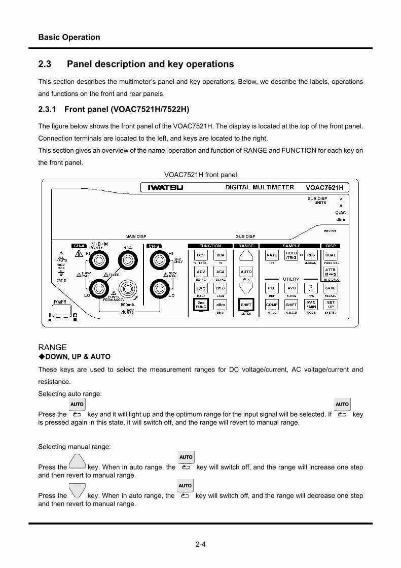
2.3.1 Front panel (VOAC7521H/7522H)
The figure below shows the front panel of the VOAC7521H. The display is located at the top of the front panel.
Connection terminals are located to the left, and keys are located to the right.
This section gives an overview of the name, operation and function of RANGE and FUNCTION for each key on
the front panel.
VOAC7521H front panel
RANGE DOWN, UP & AUTO
These keys are used to select the measurement ranges for DC voltage/current, AC voltage/current and
resistance.
Selecting auto range:
Press the key and it will light up and the optimum range for the input signal will be selected. If key is pressed again in this state, it will switch off, and the range will revert to manual range.
Selecting manual range:
Press the key. When in auto range, the key will switch off, and the range will increase one step and then revert to manual range.
Press the key. When in auto range, the key will switch off, and the range will decrease one step and then revert to manual range.
Basic Operation
2-5
*For temperature and diode measurements, the range is fixed. For frequency measurements, the range is fixed by auto range.
・ When manually configuring an unknown value, press the key several times until it reaches the
maximum range and then press the key successively to select the optimum range.
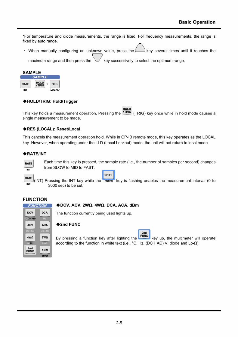
SAMPLE
HOLD/TRIG: Hold/Trigger
This key holds a measurement operation. Pressing the (TRIG) key once while in hold mode causes a single measurement to be made. RES (LOCAL): Reset/Local
This cancels the measurement operation hold. While in GP-IB remote mode, this key operates as the LOCAL key. However, when operating under the LLD (Local Lockout) mode, the unit will not return to local mode. RATE/INT
Each time this key is pressed, the sample rate (i.e., the number of samples per second) changes from SLOW to MID to FAST.
(INT) Pressing the INT key while the key is flashing enables the measurement interval (0 to 3000 sec) to be set.
FUNCTION DCV, ACV, 2WΩ, 4WΩ, DCA, ACA, dBm
The function currently being used lights up. 2nd FUNC
By pressing a function key after lighting the key up, the multimeter will operate according to the function in white text (i.e., °C, Hz, (DC+AC) V, diode and Lo-Ω).

Basic Operation
2-6
UTILITY
There is a rugged item from which the UTILITY menu has been described to be described to each key to the above figure under the item and the key by a blue character.
SHIFT
The key is used to change to shift mode (UTILITY menu). The content of the UTILITY menu set in the shift mode has the one in a right picture. The function can be selected by pushing the key that
corresponds with key has blinked.
By pressing the (ENTER) key, the multimeter will revert to normal mode from shift mode. REL/REF
The REL (relative value) calculation outputs data for the measurement value and reference value differential. REF sets the reference value. AVG/N-AVG
AVG switches the AVG calculation on and off. N-AVG: It sets the average frequency. Ω buzzer sound/Rth
This key is used to carry out a continuity test when using the 2WΩ/4WΩ function for a resistance measurement. . Rth sets the reference resistance value at which the buzzer sounds. SAVE/RECALL
SAVE saves the measurement data. The light shuts off when the data has been saved. RECALL recalls saved data. COMP/HI/LO
COMP compares the setting range or allowable setting range previously set by the user with the measurement value X. HI/LO sets the setting range or allowable setting range of a comparator calculation.
Basic Operation
2-7
SCLE/A, B, C, D
SCLE carries out calculations of ((X-A)*B /C or D/X) between the constants A, B, C and D previously set by the user and the measurement value X. A, B, C, D configures the constants A, B, C and D.
MAX/MIN/MODE
MAX/MIN obtains the maximum, minimum, average and standard deviation for the measurement results of the specified number or the calculation results. MODE specifies the number of data samples and the measurement mode (single, repeat, continuous and OFF). SETUP/SYSTEM
SETUP implements save/recall and initialize in the setup menu SYSTEM enables the multimeter’s panel settings and output conditions to be configured via the SYSTEM menu immediately after turning the power on. dBref
• Panel settings immediately after the power is switched on
• The interval setting until the unit switches to power-saving mode
• Remote control I/F setting
• Beep sound setting
• Optional I/F setting
• Auto range settings of Voltage and Resistance measurements
• Voltage check settings of the resistance circuit measurements
This enables dBm/dBV calculations by DCV, ACV, DC+ACV. The reference value at this time can be changed according to the application. (IF)
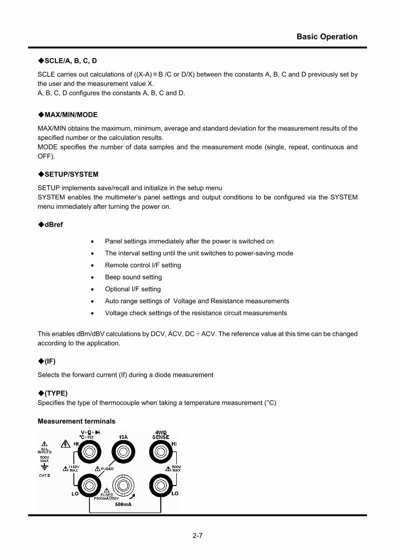
Selects the forward current (If) during a diode measurement (TYPE) Specifies the type of thermocouple when taking a temperature measurement (°C) Measurement terminals
Basic Operation
2-8
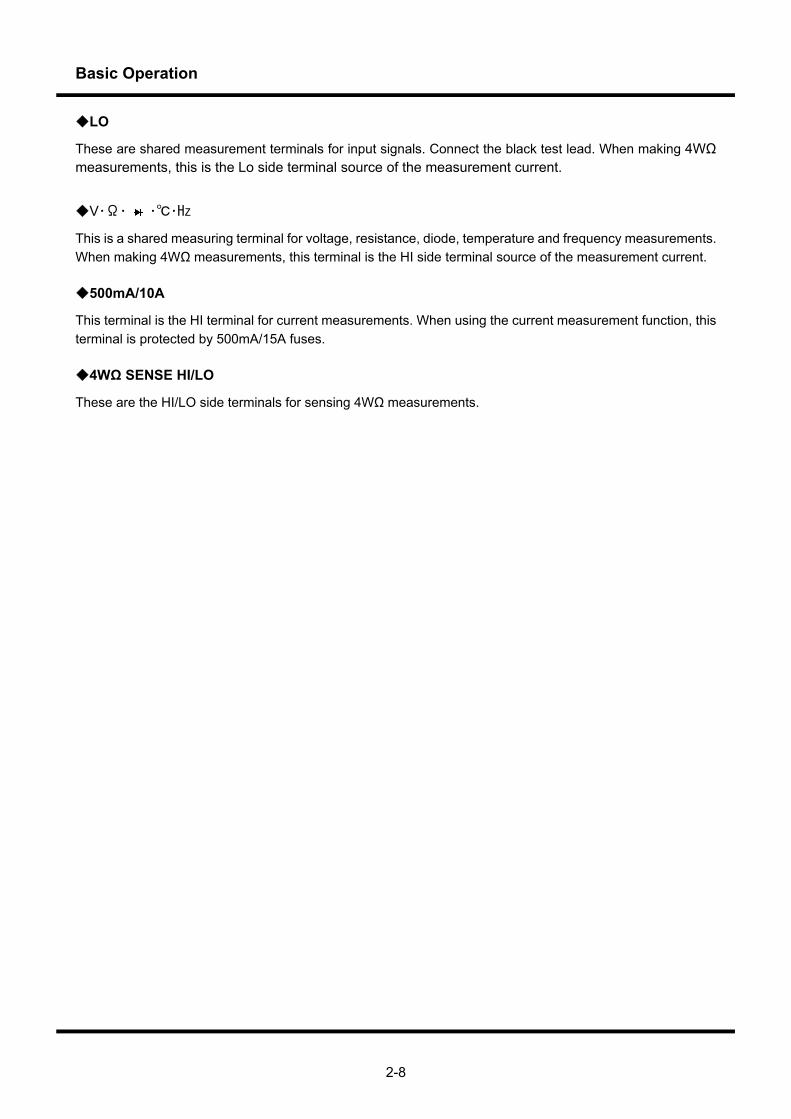
LO
These are shared measurement terminals for input signals. Connect the black test lead. When making 4WΩ measurements, this is the Lo side terminal source of the measurement current.
V・Ω・ ・・Hz
This is a shared measuring terminal for voltage, resistance, diode, temperature and frequency measurements. When making 4WΩ measurements, this terminal is the HI side terminal source of the measurement current. 500mA/10A
This terminal is the HI terminal for current measurements. When using the current measurement function, this terminal is protected by 500mA/15A fuses. 4WΩ SENSE HI/LO
These are the HI/LO side terminals for sensing 4WΩ measurements.
Basic Operation
2-9
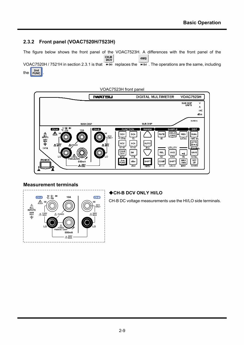
2.3.2 Front panel (VOAC7520H/7523H)
The figure below shows the front panel of the VOAC7523H. A differences with the front panel of the
VOAC7520H / 7521H in section 2.3.1 is that replaces the . The operations are the same, including
the .
VOAC7523H front panel
Measurement terminals
CH-B DCV ONLY HI/LO CH-B DC voltage measurements use the HI/LO side terminals.
Basic Operation
2-10
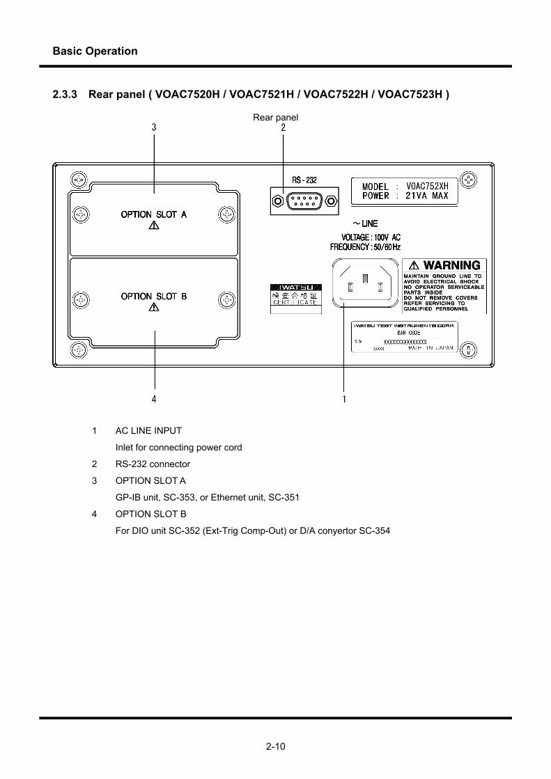
2.3.3 Rear panel ( VOAC7520H / VOAC7521H / VOAC7522H / VOAC7523H )
Rear panel
1 AC LINE INPUT
Inlet for connecting power cord
2 RS-232 connector
3 OPTION SLOT A
GP-IB unit, SC-353, or Ethernet unit, SC-351
4 OPTION SLOT B
For DIO unit SC-352 (Ext-Trig Comp-Out) or D/A conyertor SC-354
Basic Operation
2-10
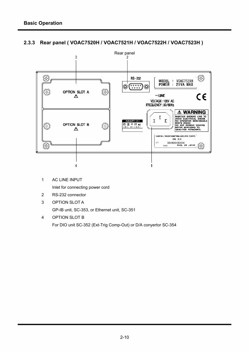
2.3.3 Rear panel ( VOAC7520H / VOAC7521H / VOAC7522H / VOAC7523H )
Rear panel
1 AC LINE INPUT
Inlet for connecting power cord
2 RS-232 connector
3 OPTION SLOT A
GP-IB unit, SC-353, or Ethernet unit, SC-351
4 OPTION SLOT B
For DIO unit SC-352 (Ext-Trig Comp-Out) or D/A conyertor SC-354
Basic Operation
2-11
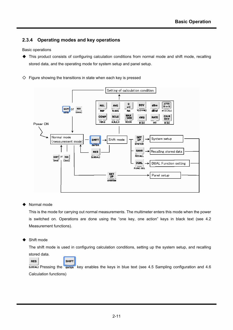
2.3.4 Operating modes and key operations
Basic operations
This product consists of configuring calculation conditions from normal mode and shift mode, recalling
stored data, and the operating mode for system setup and panel setup.
Figure showing the transitions in state when each key is pressed
Normal mode
This is the mode for carrying out normal measurements. The multimeter enters this mode when the power
is switched on. Operations are done using the “one key, one action” keys in black text (see 4.2
Measurement functions).
Shift mode
The shift mode is used in configuring calculation conditions, setting up the system setup, and recalling
stored data.
Pressing the key enables the keys in blue text (see 4.5 Sampling configuration and 4.6
Calculation functions)
Basic Operation
2-12
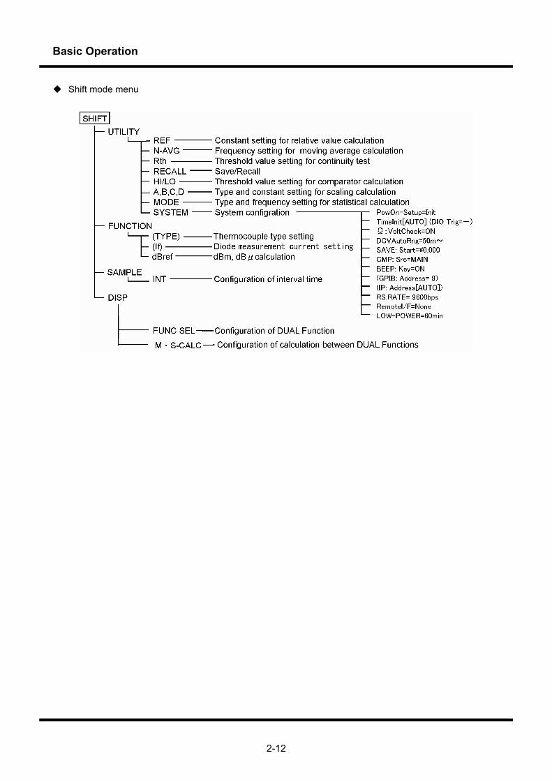
Shift mode menu
Basic Operation
2-13
2.4 Display
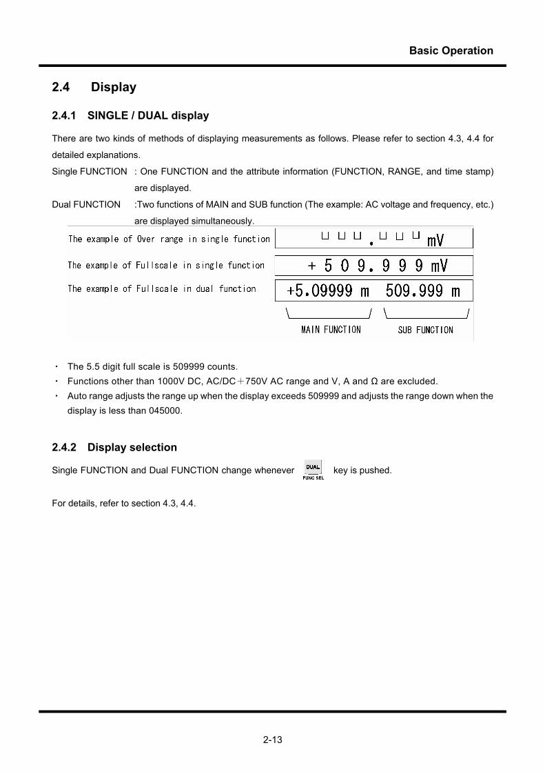
2.4.1 SINGLE / DUAL display
There are two kinds of methods of displaying measurements as follows. Please refer to section 4.3, 4.4 for
detailed explanations.
Single FUNCTION : One FUNCTION and the attribute information (FUNCTION, RANGE, and time stamp)
are displayed.
Dual FUNCTION :Two functions of MAIN and SUB function (The example: AC voltage and frequency, etc.)
are displayed simultaneously.
・ The 5.5 digit full scale is 509999 counts. ・ Functions other than 1000V DC, AC/DC+750V AC range and V, A and Ω are excluded. ・ Auto range adjusts the range up when the display exceeds 509999 and adjusts the range down when the
display is less than 045000.
2.4.2 Display selection
Single FUNCTION and Dual FUNCTION change whenever key is pushed.
For details, refer to section 4.3, 4.4.
Basic Operation
2-14
Memo
Operating Principles
1234567
Chapter 3 Operating Principles
Operating Principles
3-2
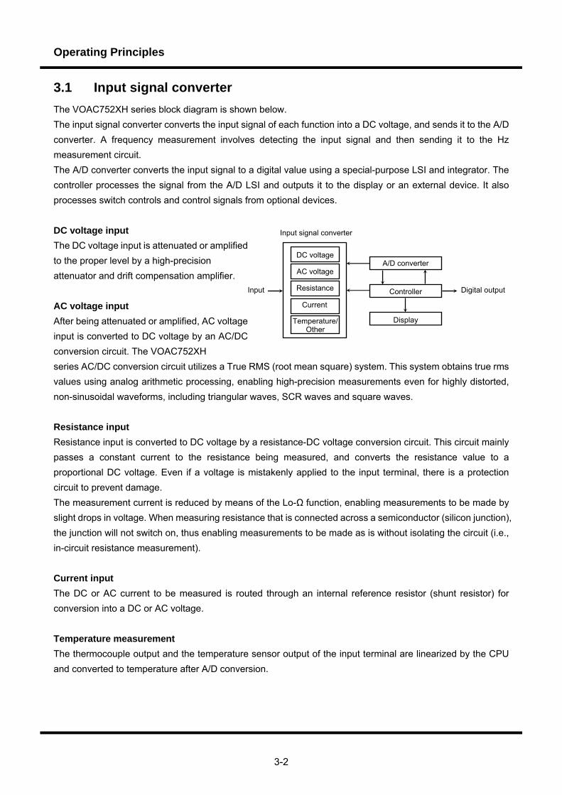
3.1 Input signal converter The VOAC752XH series block diagram is shown below. The input signal converter converts the input signal of each function into a DC voltage, and sends it to the A/D converter. A frequency measurement involves detecting the input signal and then sending it to the Hz measurement circuit. The A/D converter converts the input signal to a digital value using a special-purpose LSI and integrator. The controller processes the signal from the A/D LSI and outputs it to the display or an external device. It also processes switch controls and control signals from optional devices. DC voltage input The DC voltage input is attenuated or amplified to the proper level by a high-precision attenuator and drift compensation amplifier. AC voltage input After being attenuated or amplified, AC voltage input is converted to DC voltage by an AC/DC conversion circuit. The VOAC752XH series AC/DC conversion circuit utilizes a True RMS (root mean square) system. This system obtains true rms values using analog arithmetic processing, enabling high-precision measurements even for highly distorted, non-sinusoidal waveforms, including triangular waves, SCR waves and square waves. Resistance input Resistance input is converted to DC voltage by a resistance-DC voltage conversion circuit. This circuit mainly passes a constant current to the resistance being measured, and converts the resistance value to a proportional DC voltage. Even if a voltage is mistakenly applied to the input terminal, there is a protection circuit to prevent damage. The measurement current is reduced by means of the Lo-Ω function, enabling measurements to be made by slight drops in voltage. When measuring resistance that is connected across a semiconductor (silicon junction), the junction will not switch on, thus enabling measurements to be made as is without isolating the circuit (i.e., in-circuit resistance measurement). Current input The DC or AC current to be measured is routed through an internal reference resistor (shunt resistor) for conversion into a DC or AC voltage. Temperature measurement The thermocouple output and the temperature sensor output of the input terminal are linearized by the CPU and converted to temperature after A/D conversion.
Input signal converter
DC voltage
AC voltage
Resistance
Current
Temperature/Other
A/D converter
Controller
Display
Digital output Input
Operating Principles
3-3
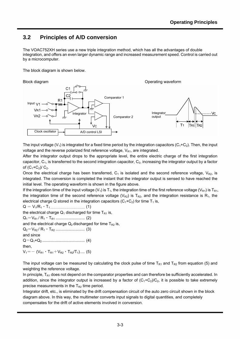
3.2 Principles of A/D conversion The VOAC752XH series use a new triple integration method, which has all the advantages of double integration, and offers an even larger dynamic range and increased measurement speed. Control is carried out by a microcomputer. The block diagram is shown below. Block diagram Operating waveform
The input voltage (V1) is integrated for a fixed time period by the integration capacitors (C1+C2). Then, the input voltage and the reverse polarized first reference voltage, VR1, are integrated. After the integrator output drops to the appropriate level, the entire electric charge of the first integration capacitor, C1, is transferred to the second integration capacitor, C2, increasing the integrator output by a factor of (C1+C2)/ C2. Once the electrical charge has been transferred, C1 is isolated and the second reference voltage, VR2, is integrated. The conversion is completed the instant that the integrator output is sensed to have reached the initial level. The operating waveform is shown in the figure above. If the integration time of the input voltage (V1) is T1, the integration time of the first reference voltage (VR1) is TR1, the integration time of the second reference voltage (VR2) is TR2, and the integration resistance is R1, the electrical charge Q stored in the integration capacitors (C1+C2) for time T1 is, Q = V1/R1・T1................................................ (1) the electrical charge Q1 discharged for time TR1 is, Q1=VR1 / R1・TR1 .......................... (2) and the electrical charge Q2 discharged for time TR2 is, Q2=VR2 / R1・TR2 .......................... (3) and since Q=Q1+Q2 ...................................... (4) then, V1=- (VR1・TR1+VR2・TR2/T1) .... (5) The input voltage can be measured by calculating the clock pulse of time TR1 and TR2 from equation (5) and weighting the reference voltage. In principle, TR1 does not depend on the comparator properties and can therefore be sufficiently accelerated. In addition, since the integrator output is increased by a factor of (C1+C2)/C2, it is possible to take extremely precise measurements in the TR2 time period. Integrator drift, etc., is eliminated by the drift compensation circuit of the auto zero circuit shown in the block diagram above. In this way, the multimeter converts input signals to digital quantities, and completely compensates for the drift of active elements involved in conversion.
Input
Integrator
Comparator 1
Comparator 2
Clock oscillator A/D control LSI
Integrator output

Operating Principles
3-4
Memo
Measurement Methods
1234567
Chapter 4 Measurement Methods Summary This chapter describes functions and operations.
Measurement Methods
4-2
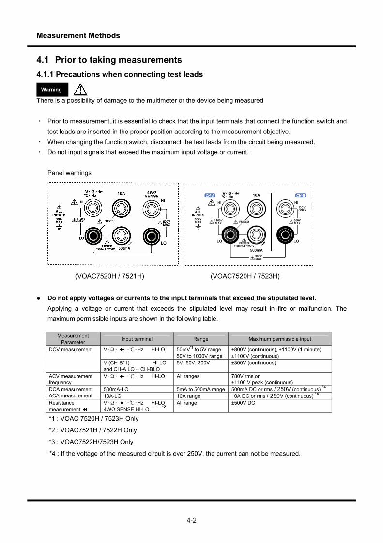
4.1 Prior to taking measurements 4.1.1 Precautions when connecting test leads
There is a possibility of damage to the multimeter or the device being measured ・ Prior to measurement, it is essential to check that the input terminals that connect the function switch and
test leads are inserted in the proper position according to the measurement objective. ・ When changing the function switch, disconnect the test leads from the circuit being measured. ・ Do not input signals that exceed the maximum input voltage or current.
Panel warnings
(VOAC7520H / 7521H) (VOAC7520H / 7523H)
Do not apply voltages or currents to the input terminals that exceed the stipulated level. Applying a voltage or current that exceeds the stipulated level may result in fire or malfunction. The
maximum permissible inputs are shown in the following table.
Measurement Parameter Input terminal Range Maximum permissible input
V・Ω・ ・・Hz HI-LO 50mV*3 to 5V range 50V to 1000V range
±800V (continuous), ±1100V (1 minute) ±1100V (continuous)
DCV measurement
V (CH-B*1) HI-LO and CH-A LO ~ CH-BLO
5V, 50V, 300V ±300V (continuous)
ACV measurement frequency
V・Ω・ ・・Hz HI-LO All ranges 780V rms or ±1100 V peak (continuous)
500mA-LO 5mA to 500mA range 500mA DC or rms / 250V (continuous) *4 DCA measurement ACA measurement 10A-LO 10A range 10A DC or rms / 250V (continuous) *4 Resistance measurement
V・Ω・ ・・Hz HI-LO 4WΩ SENSE HI-LO *2
All range ±500V DC
*1 : VOAC 7520H / 7523H Only
*2 : VOAC7521H / 7522H Only
*3 : VOAC7522H/7523H Only
*4 : If the voltage of the measured circuit is over 250V, the current can not be measured.
Warning
Measurement Methods
4-3
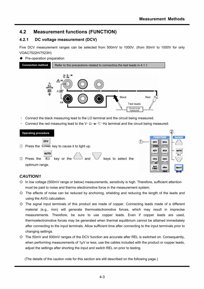
4.2 Measurement functions (FUNCTION) 4.2.1 DC voltage measurement (DCV)
Five DCV measurement ranges can be selected from 500mV to 1000V. (from 50mV to 1000V for only VOAC7522H/7523H) Pre-operation preparation
・ Connect the black measuring lead to the LO terminal and the circuit being measured. ・ Connect the red measuring lead to the V・Ω・ ・・Hz terminal and the circuit being measured.
① Press the key to cause it to light up.
② Press the key or the and keys to select the
optimum range.
CAUTION!! In low voltage (500mV range or below) measurements, sensitivity is high. Therefore, sufficient attention
must be paid to noise and thermo electromotive force in the measurement system. The effects of noise can be reduced by anchoring, shielding and reducing the length of the leads and
using the AVG calculation. The signal input terminals of this product are made of copper. Connecting leads made of a different
material (e.g., iron) will generate thermoelectromotive forces, which may result in imprecise measurements. Therefore, be sure to use copper leads. Even if copper leads are used, thermoelectromotive forces may be generated when thermal equilibrium cannot be attained immediately after connecting to the input terminals. Allow sufficient time after connecting to the input terminals prior to changing settings.
The 50mV and 500mV ranges of the DCV function are accurate after REL is switched on. Consequently, when performing measurements of 1μV or less, use the cables included with the product or copper leads, adjust the settings after shorting the input and switch REL on prior to testing.
(The details of the caution note for this section are still described on the following page.)
Operating procedure
Refer to the precautions related to connecting the test leads in 4.1.1 Connection method
Test leadsCircuit to be measured
Black Red
Measurement Methods
4-4
When switching to DC measurements after testing currents of 2A or above, adjust the settings after leaving the product on standby until stable at the minimum input (i.e., shorted). Caution is particularly necessary when performing high-sensitivity measurements.
In contrast to the response time of about 0.25 seconds/sample for SLOW samples in the 500mV-1000V DC range, the 2 seconds/sample response in the 50mV DC range for the VOAC7522H/7523H is slow. When the 50mV range is unnecessary and a high-speed AUTO range response is necessary, the DC 50mV range can be omitted from the AUTO range. See section 4.10.11 for details.
Measurement Methods
4-5
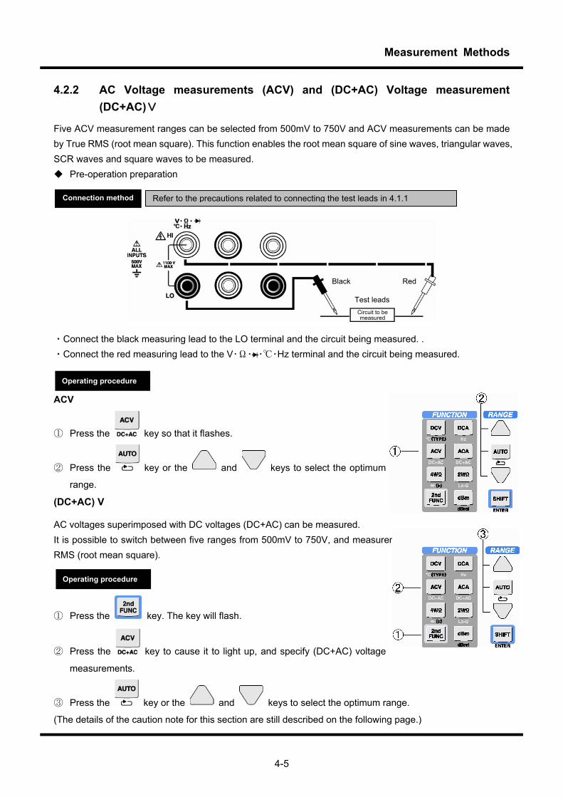
4.2.2 AC Voltage measurements (ACV) and (DC+AC) Voltage measurement
(DC+AC)V
Five ACV measurement ranges can be selected from 500mV to 750V and ACV measurements can be made by True RMS (root mean square). This function enables the root mean square of sine waves, triangular waves, SCR waves and square waves to be measured. Pre-operation preparation
・Connect the black measuring lead to the LO terminal and the circuit being measured. . ・Connect the red measuring lead to the V・Ω・ ・・Hz terminal and the circuit being measured. ACV
① Press the key so that it flashes.
② Press the key or the and keys to select the optimum
range.
(DC+AC) V
AC voltages superimposed with DC voltages (DC+AC) can be measured. It is possible to switch between five ranges from 500mV to 750V, and measurements can be made by True RMS (root mean square).
① Press the
key. The key will flash.
② Press the key to cause it to light up, and specify (DC+AC) voltage
measurements.
③ Press the key or the and keys to select the optimum range.
(The details of the caution note for this section are still described on the following page.)
Refer to the precautions related to connecting the test leads in 4.1.1 Connection method
Test leadsCircuit to be measured
Black Red
Operating procedure
Operating procedure
Measurement Methods
4-6
CAUTION!! Procedure for measuring low-frequency voltages and currents When the sample rate is SLOW, the time (Settling time) to wait for the stabilization of the internal circuit
can be shortened by selecting the appropriate AC filter according to the frequency of the measurement signal. If the AC filter is set to "200Hz-" when the frequency of the measurement signal is 200Hz or more, the change of the range and Function becomes high-speed. Please refer to section 4.10.12 for details. Still, when the sample rate is MID/FAST, the AC filter is fixed to "200Hz-".
The display might be uneven according to the input signal though it is enough in regulated accuracy in the measurement of a low frequency (about 15Hz-40Hz). In this case, a steady measurement can be done by averaging the uneveness in using the AVG calculation. Please set the AVG frequency as required.
When switching to DC measurements after testing currents of 2A or above, adjust the settings after leaving the product on standby until stable at the minimum input (i.e., shorted). Adequate caution is particularly necessary when taking high-sensitivity measurements.
Measurement Methods
4-7
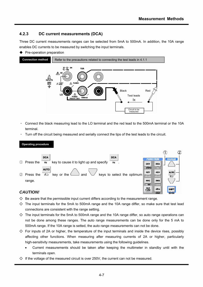
4.2.3 DC current measurements (DCA)
Three DC current measurements ranges can be selected from 5mA to 500mA. In addition, the 10A range enables DC currents to be measured by switching the input terminals. Pre-operation preparation
・ Connect the black measuring lead to the LO terminal and the red lead to the 500mA terminal or the 10A
terminal. ・ Turn off the circuit being measured and serially connect the tips of the test leads to the circuit.
① Press the key to cause it to light up and specify .
② Press the key or the and keys to select the optimum
range.
CAUTION! Be aware that the permissible input current differs according to the measurement range. The input terminals for the 5mA to 500mA range and the 10A range differ, so make sure that test lead
connections are consistent with the range setting. The input terminals for the 5mA to 500mA range and the 10A range differ, so auto range operations can
not be done among these ranges. The auto range measurements can be done only for the 5 mA to 500mA range. If the 10A range is setted, the auto range measurements can not be done.
For inputs of 2A or higher, the temperature of the input terminals and inside the device rises, possibly affecting other functions. When measuring after measuring currents of 2A or higher, particularly high-sensitivity measurements, take measurements using the following guidelines. • Current measurements should be taken after keeping the multimeter in standby until with the
terminals open. If the voltage of the measured circuit is over 250V, the current can not be measured.
Refer to the precautions related to connecting the test leads in 4.1.1 Connection method
Operating procedure
Test leads
Circuit to be measured
Black Red

Measurement Methods
4-8
4.2.4 AC current measurements (ACA) and (DC+AC) current measurements ((DC+AC)A)
Three ACA measurement ranges can be selected from 5mA to 500mA. In addition, the 10A range enables AC currents to be measured by switching the input terminals and using True RMS (root mean square) in the analog calculation mode. This function enables the root mean square of sine waves, triangular waves, SCR waves and square waves to be measured.
・ Connect the black measuring lead to the LO terminal and the red lead to the 500 mA terminal. ・ Turn off the circuit being measured, and serially connect the tips of the test leads to the circuit. AC A
① Press the key to cause it to light up, and specify .
② Press the key or the and keys to select the optimum
range.
(DC+AC) A
① Press the key. The key will flash.
② Press the (DC+AC) key so that the and keys
light up and specify (DC+AC) current measurements.
③ Press the key or the and keys to select
the optimum range.
Refer to the precautions related to connecting the test leads in 4.1.1 Connection method
Operating procedure
Test leads
Black Red
Circuit to be measured
Measurement Methods
4-9
(The details of the caution note for this section are still described on the following page.) CAUTION!! Be aware that the permissible input current differs according to the measurement range. The input terminals for the 5mA to 500mA range and the 10A range differ, so make sure that connection
of the test leads is consistent with the range setting. The input terminals for the 5mA to 500mA range and the 10A range differ, so auto range operations can
not be done among these ranges. The auto range measurements can be done only for the 5 mA to 500mA range. If the 10A range is setted, the auto range measurements can not be done.
For inputs of 2A or higher, the temperature of the input terminals and inside the device rises, and may affect other functions. When measuring after measuring currents of 2A or higher, particularly high-sensitivity measurements, take measurements after the temperature inside the multimeter has stabilized. Current measurements should be taken after keeping the multimeter in standby until with the terminals open.
If the voltage of the measured circuit is over 250V, the current can not be measured. Procedure for measuring low-frequency voltages and currents
When the sample rate is SLOW, the time (Settling time) to wait for the stabilization of the internal circuit can be shortened by selecting the appropriate AC filter according to the frequency of the measurement signal. If the AC filter is set to "200Hz-" when the frequency of the measurement signal is 200Hz or more, the change of the range and Function becomes high-speed. Please refer to section 4.10.12 for details. Still, when the sample rate is MID/FAST, the AC filter is fixed to "200Hz-".
The display might be uneven according to the input signal though it is enough in regulated accuracy in the measurement of a low frequency (about 15Hz-40Hz). In this case, a steady measurement can be done by averaging the uneveness in using the AVG calculation. Please set the AVG frequency as required.
Measurement Methods
4-10
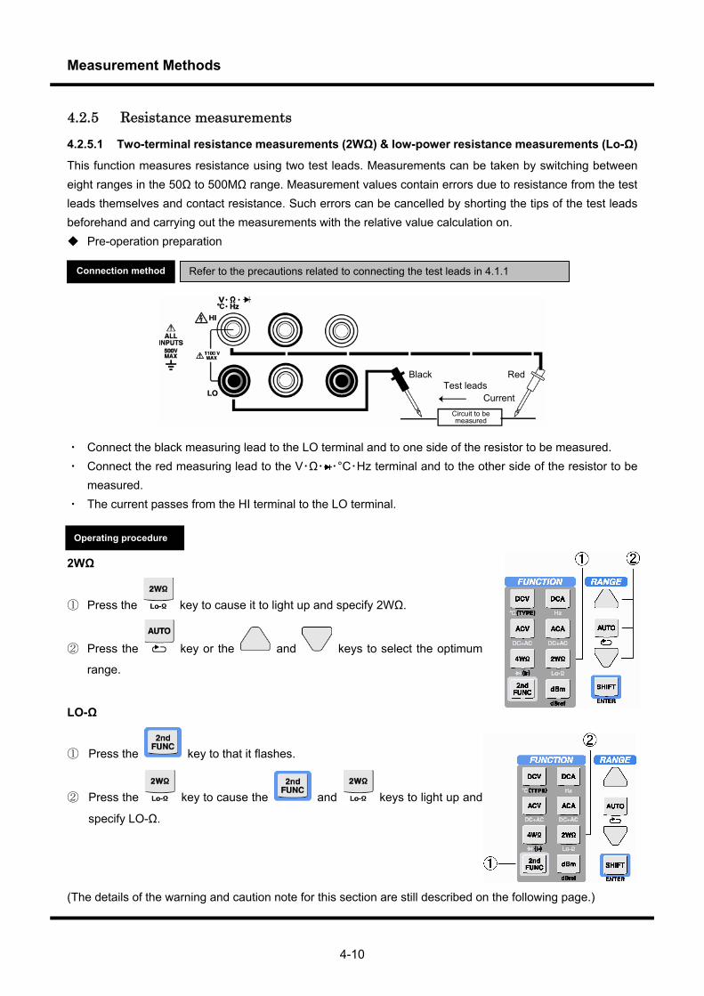
4.2.5 Resistance measurements
4.2.5.1 Two-terminal resistance measurements (2WΩ) & low-power resistance measurements (Lo-Ω)
This function measures resistance using two test leads. Measurements can be taken by switching between eight ranges in the 50Ω to 500MΩ range. Measurement values contain errors due to resistance from the test leads themselves and contact resistance. Such errors can be cancelled by shorting the tips of the test leads beforehand and carrying out the measurements with the relative value calculation on. Pre-operation preparation
・ Connect the black measuring lead to the LO terminal and to one side of the resistor to be measured. ・ Connect the red measuring lead to the V・Ω・ ・°C・Hz terminal and to the other side of the resistor to be
measured. ・ The current passes from the HI terminal to the LO terminal.
2WΩ
① Press the key to cause it to light up and specify 2WΩ.
② Press the key or the and keys to select the optimum
range.
LO-Ω
① Press the key to that it flashes.
② Press the key to cause the and keys to light up and
specify LO-Ω.
(The details of the warning and caution note for this section are still described on the following page.)
Refer to the precautions related to connecting the test leads in 4.1.1 Connection method
Test leads
Circuit to be measured
Black Red
Current
Operating procedure
Measurement Methods
4-11
Applying voltage to the resistance measurement terminal immediately after switching to the resistance
measurement function from another function may result in damage. Therefore, use adequate caution.
To prevent damage, this product has a protective function that automatically measures the voltage under (DC+AC)V and displays a message if it detects a high voltage. The default setting for this voltage check function is ON. To switch this function off, change the VoltCheck system setting to OFF. Refer to section 4.10.10 for details and the procedure for switching the function off.
If a voltage exceeding approximately 100V is detected by the (DC+AC)V function, “!Voltage_Detect” will be displayed and the product will forcefully return to the original function. However, this protective operation is not guaranteed for voltages with high frequencies or large peaks that are not guaranteed by (DC+AC)V. In addition, measurements cannot be taken correctly under conditions in which voltage is applied to the resistance being tested. Therefore, when measuring resistance within a circuit, make sure that voltage is not being applied to the resistance being tested.
CAUTION!! Anchor the test leads when measuring high resistances. The AVG calculation and the shortening and
shorting of the cables are effective in minimizing the effects of humming noise. The product is subject to the effects of contact resistance from the test leads and thermoelectromotive
forces from the input terminals in low-resistance measurements. Therefore, use the product after the measurement readout has stabilized following connection.
When switching to a resistance measurement after measuring a current of 2A or above, do so after leaving the product on standby until stable at the minimum input (i.e., shorted). Caution is particularly necessary when taking high-sensitivity measurements.
In contrast to a response time of about one second for SLOW samples of 50Ω-50MΩ for 2WΩ, the 5 seconds response in the 500MΩ range is slow. When the 500MΩ range is unnecessary and a high-speed AUTO range response is necessary, the 500MΩ range can be omitted from the AUTO range. See section 4.10.10 for details.
Warning
Measurement Methods
4-12
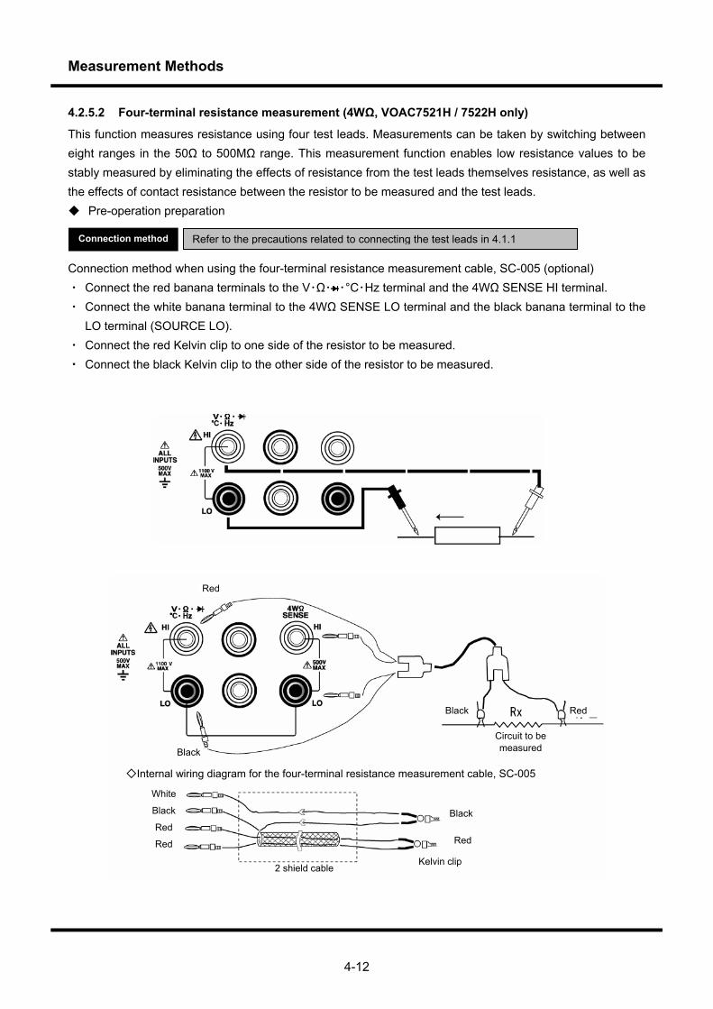
4.2.5.2 Four-terminal resistance measurement (4WΩ, VOAC7521H / 7522H only)
This function measures resistance using four test leads. Measurements can be taken by switching between eight ranges in the 50Ω to 500MΩ range. This measurement function enables low resistance values to be stably measured by eliminating the effects of resistance from the test leads themselves resistance, as well as the effects of contact resistance between the resistor to be measured and the test leads. Pre-operation preparation Connection method when using the four-terminal resistance measurement cable, SC-005 (optional) ・ Connect the red banana terminals to the V・Ω・ ・°C・Hz terminal and the 4WΩ SENSE HI terminal. ・ Connect the white banana terminal to the 4WΩ SENSE LO terminal and the black banana terminal to the
LO terminal (SOURCE LO). ・ Connect the red Kelvin clip to one side of the resistor to be measured. ・ Connect the black Kelvin clip to the other side of the resistor to be measured.
Refer to the precautions related to connecting the test leads in 4.1.1 Connection method
Internal wiring diagram for the four-terminal resistance measurement cable, SC-005
Circuit to be measured
Red Black
Black
Red
Kelvin clip 2 shield cable
Red
Black
White
Black
Red
Red
Measurement Methods
4-13
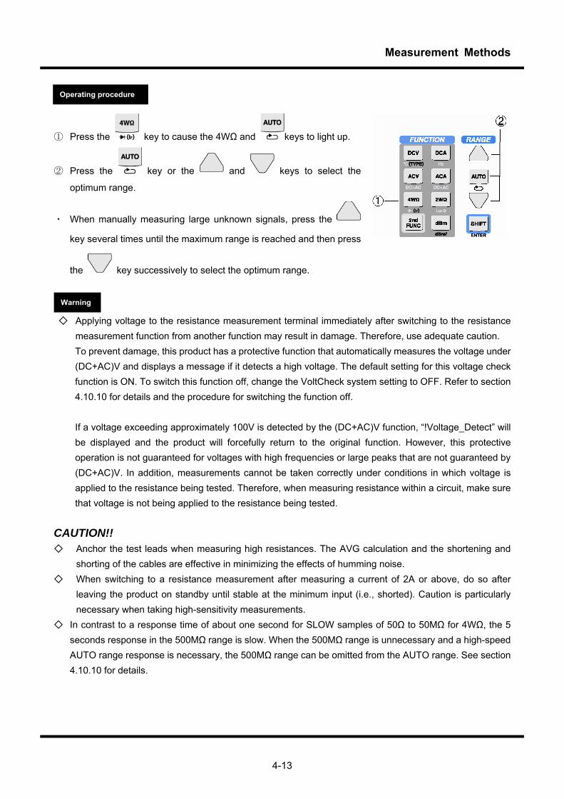
① Press the key to cause the 4WΩ and keys to light up.
② Press the key or the and keys to select the
optimum range.
・ When manually measuring large unknown signals, press the
key several times until the maximum range is reached and then press
the key successively to select the optimum range.
Applying voltage to the resistance measurement terminal immediately after switching to the resistance
measurement function from another function may result in damage. Therefore, use adequate caution. To prevent damage, this product has a protective function that automatically measures the voltage under (DC+AC)V and displays a message if it detects a high voltage. The default setting for this voltage check function is ON. To switch this function off, change the VoltCheck system setting to OFF. Refer to section 4.10.10 for details and the procedure for switching the function off.
If a voltage exceeding approximately 100V is detected by the (DC+AC)V function, “!Voltage_Detect” will be displayed and the product will forcefully return to the original function. However, this protective operation is not guaranteed for voltages with high frequencies or large peaks that are not guaranteed by (DC+AC)V. In addition, measurements cannot be taken correctly under conditions in which voltage is applied to the resistance being tested. Therefore, when measuring resistance within a circuit, make sure that voltage is not being applied to the resistance being tested.
CAUTION!! Anchor the test leads when measuring high resistances. The AVG calculation and the shortening and
shorting of the cables are effective in minimizing the effects of humming noise. When switching to a resistance measurement after measuring a current of 2A or above, do so after
leaving the product on standby until stable at the minimum input (i.e., shorted). Caution is particularly necessary when taking high-sensitivity measurements.
In contrast to a response time of about one second for SLOW samples of 50Ω to 50MΩ for 4WΩ, the 5 seconds response in the 500MΩ range is slow. When the 500MΩ range is unnecessary and a high-speed AUTO range response is necessary, the 500MΩ range can be omitted from the AUTO range. See section 4.10.10 for details.
Operating procedure
Warning
Measurement Methods
4-14
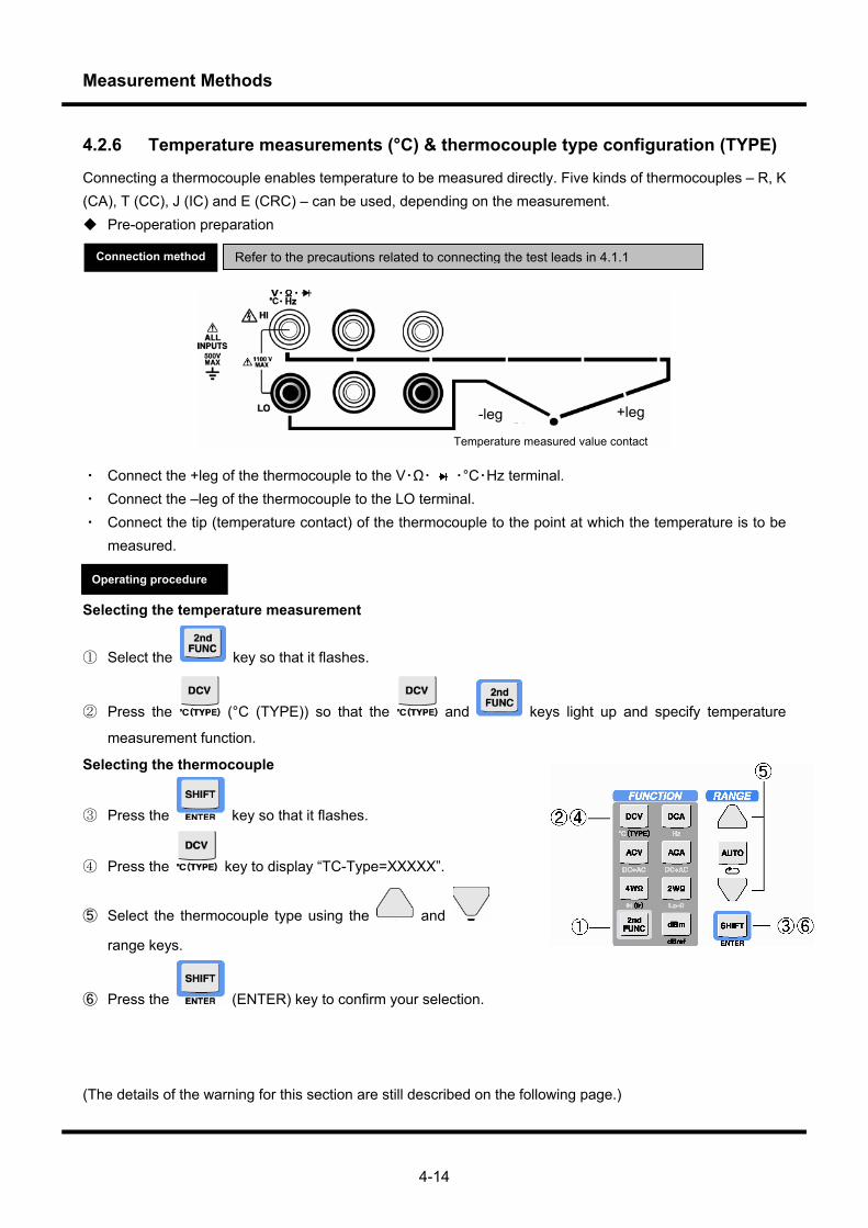
4.2.6 Temperature measurements (°C) & thermocouple type configuration (TYPE)
Connecting a thermocouple enables temperature to be measured directly. Five kinds of thermocouples – R, K (CA), T (CC), J (IC) and E (CRC) – can be used, depending on the measurement. Pre-operation preparation
・ Connect the +leg of the thermocouple to the V・Ω・ ・°C・Hz terminal. ・ Connect the –leg of the thermocouple to the LO terminal. ・ Connect the tip (temperature contact) of the thermocouple to the point at which the temperature is to be
measured. Selecting the temperature measurement
① Select the key so that it flashes.
② Press the (°C (TYPE)) so that the and keys light up and specify temperature
measurement function.
Selecting the thermocouple
③ Press the key so that it flashes.
④ Press the key to display “TC-Type=XXXXX”.
⑤ Select the thermocouple type using the and
range keys.
⑥ Press the (ENTER) key to confirm your selection.
(The details of the warning for this section are still described on the following page.)
Refer to the precautions related to connecting the test leads in 4.1.1 Connection method
Operating procedure
Temperature measured value contact
-leg +leg
Measurement Methods
4-15
When precisely measuring the temperature, pay attention to the following Parameters: ・ Ensure that the point you wish to measure the temperature of and the tip of the thermocouple are in
sufficient contact with each other. ・ When measuring the temperature, the temperature of the input terminal HI-LO must be stable. The
temperature may become unstable immediately after attaching the thermocouple. Also, ensure that the input terminals are not exposed to drafts during measurement.
・ When measuring a liquid, take the measurement after mixing the liquid well to ensure a uniform temperature.
Warning
Measurement Methods
4-16
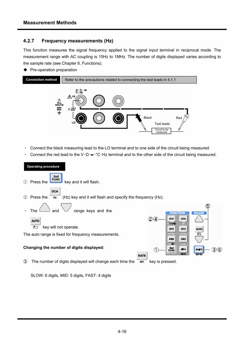
4.2.7 Frequency measurements (Hz)
This function measures the signal frequency applied to the signal input terminal in reciprocal mode. The measurement range with AC coupling is 15Hz to 1MHz. The number of digits displayed varies according to the sample rate (see Chapter 6, Functions). Pre-operation preparation
・ Connect the black measuring lead to the LO terminal and to one side of the circuit being measured. ・ Connect the red lead to the V・Ω・ ・°C・Hz terminal and to the other side of the circuit being measured.
① Press the key and it will flash.
② Press the (Hz) key and it will flash and specify the frequency (Hz).
・ The and range keys and the
key will not operate.
The auto range is fixed for frequency measurements. Changing the number of digits displayed:
③ The number of digits displayed will change each time the key is pressed.
SLOW: 6 digits, MID: 5 digits, FAST: 4 digits
Refer to the precautions related to connecting the test leads in 4.1.1 Connection method
Operating procedure
Test leads
Circuit to be measured
Black Red
Measurement Methods
4-17
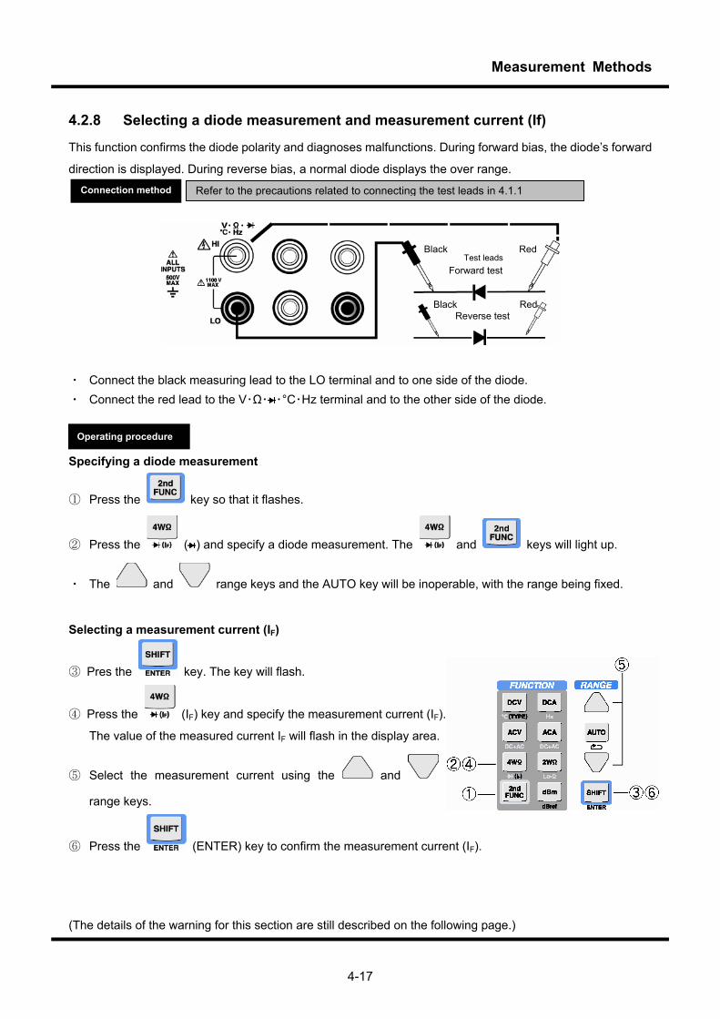
4.2.8 Selecting a diode measurement and measurement current (If)
This function confirms the diode polarity and diagnoses malfunctions. During forward bias, the diode’s forward
direction is displayed. During reverse bias, a normal diode displays the over range.
・ Connect the black measuring lead to the LO terminal and to one side of the diode. ・ Connect the red lead to the V・Ω・ ・°C・Hz terminal and to the other side of the diode.
Specifying a diode measurement
① Press the key so that it flashes.
② Press the ( ) and specify a diode measurement. The and keys will light up.
・ The and range keys and the AUTO key will be inoperable, with the range being fixed.
Selecting a measurement current (IF)
③ Pres the key. The key will flash.
④ Press the (IF) key and specify the measurement current (IF).
The value of the measured current IF will flash in the display area.
⑤ Select the measurement current using the and
range keys.
⑥ Press the (ENTER) key to confirm the measurement current (IF).
(The details of the warning for this section are still described on the following page.)
Refer to the precautions related to connecting the test leads in 4.1.1 Connection method
Operating procedure
Test leads Black Red
Forward test
Black Red Reverse test
Measurement Methods
4-18
Applying voltage to the resistance measurement terminal immediately after switching to the resistance
measurement function from another function may result in damage. Therefore, use adequate caution. To prevent damage, this product has a protective function that automatically measures the voltage under (DC+AC)V and displays a message if it detects a high voltage.The default setting for this voltage check function is ON. To switch this function off, change the VoltCheck system setting to OFF. See section 4.10.10 for details and for the procedure for switching the function off. If a voltage exceeding approximately 100V is detected by the (DC+AC) V function, “!Voltage_Detect” will be displayed and the product will forcefully return to the original function. However, this protective operation is not guaranteed for voltages with high frequencies or large peaks that are not guaranteed by (DC+AC)V. In addition, measurements cannot be taken correctly under conditions in which voltage is applied to the diode being tested. Therefore, when testing a diode within a circuit, make sure that voltage is not being applied to the diode being tested.
Warning
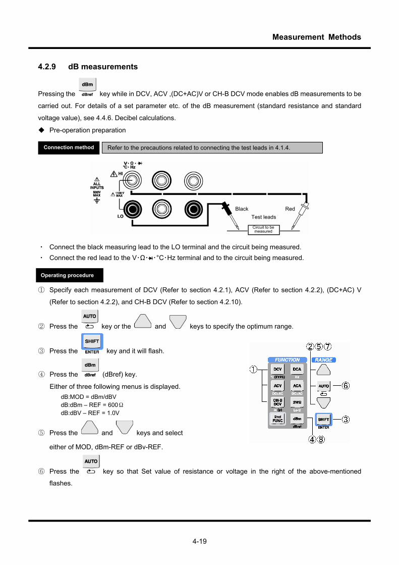
Measurement Methods
4-19
4.2.9 dB measurements
Pressing the key while in DCV, ACV ,(DC+AC)V or CH-B DCV mode enables dB measurements to be
carried out. For details of a set parameter etc. of the dB measurement (standard resistance and standard
voltage value), see 4.4.6. Decibel calculations.
Pre-operation preparation
・ Connect the black measuring lead to the LO terminal and the circuit being measured. ・ Connect the red lead to the V・Ω・ ・°C・Hz terminal and to the circuit being measured. ① Specify each measurement of DCV (Refer to section 4.2.1), ACV (Refer to section 4.2.2), (DC+AC) V
(Refer to section 4.2.2), and CH-B DCV (Refer to section 4.2.10).
② Press the key or the and keys to specify the optimum range.
③ Press the key and it will flash.
④ Press the (dBref) key.
Either of three following menus is displayed. dB:MOD = dBm/dBV dB:dBm – REF = 600Ω dB:dBV – REF = 1.0V
⑤ Press the and keys and select
either of MOD, dBm-REF or dBv-REF.
⑥ Press the key so that Set value of resistance or voltage in the right of the above-mentioned
flashes.
Refer to the precautions related to connecting the test leads in 4.1.4. Connection method
Operating procedure
Test leads
Circuit to be measured
Black Red

Measurement Methods
4-20
⑦ Use the and range keys to select the reference resistance value or the reference voltage
value .
⑧ Press the key to implement the dBm calculation.
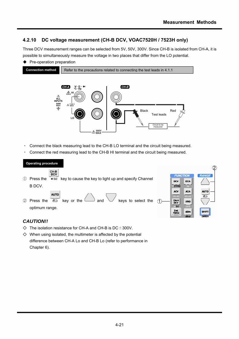
Measurement Methods
4-21
4.2.10 DC voltage measurement (CH-B DCV, VOAC7520H / 7523H only)
Three DCV measurement ranges can be selected from 5V, 50V, 300V. Since CH-B is isolated from CH-A, it is possible to simultaneously measure the voltage in two places that differ from the LO potential. Pre-operation preparation
黒 赤テストリード
・ Connect the black measuring lead to the CH-B LO terminal and the circuit being measured. ・ Connect the red measuring lead to the CH-B HI terminal and the circuit being measured.
① Press the key to cause the key to light up and specify Channel
B DCV.
② Press the key or the and keys to select the
optimum range.
CAUTION!! The isolation resistance for CH-A and CH-B is DC±300V. When using isolated, the multimeter is affected by the potential
difference between CH-A Lo and CH-B Lo (refer to performance in Chapter 6).
Operating procedure
Refer to the precautions related to connecting the test leads in 4.1.1 Connection method
Test leads
Circuit to be measured
Black Red

Measurement Methods
4-22
4.3 Dual FUNCTION During Dual FUNCTION operation, the system alternately switches between two measurement functions to perform measurement, while simultaneously displaying the measurement results. This function can be used, for example, to simultaneously measure voltage and current or voltage and frequency. Especially for models (VOAC7520H, VOAC7523H) that have an isolated direct current voltage measurement channel (CH-B DCV), this function can be used to compare the voltages of different circuits or easily measure the potentials of different components in the same circuit.
Below, in addition to the Dual FUNCTION, the term Single FUNCTION is used to refer to using one function to
perform normal measurement.
Switching between single and Dual FUNCTION operation
Each time the key is pressed, the operation switches between single and Dual FUNCTION
operation. While Dual FUNCTIONs are
used to perform measurement, the key lights up. In addition,
the display is split into a left and right area, and the two measurement results are
simultaneously displayed.
The measurement function for which results are displayed on the left side is called the main function, and the
function for which results are displayed on the right is called the sub function. When operation is switched
from single to Dual FUNCTION operation, the function that performs measurement during Single FUNCTION
operation is assigned to the main-function side of Dual FUNCTIONs. Similarly, when operation is switched
from dual to Single FUNCTION operation, the function assigned to the main-function side is used for Single
FUNCTION measurement.
Single
FUNCTION ±5.09999 mV__
Dual
FUNCTION ±509999 m±509999k
Measurement result on the main-function side Measurement result on the sub-function side
CAUTION!!
Unlike Single FUNCTION operation, the following restrictions apply during Dual FUNCTION operation:
・ The sampling rate slows down without any relation to the rate setting of SLOW/MID/FAST because it is
Operating procedure
Measurement Methods
4-23
necessary to wait for the internal circuit to stabilize when the function is switched.
・ Comparator calculation results, types of statistical data, functions, ranges, and timestamp attribute
information are not displayed.
・ No measurement units are displayed on the main-function side. The measurement units for the
sub-function area are indicated by the SUB DISP UNITS LEDs.
4.3.1 Dual FUNCTION operation
During Dual FUNCTION operation, when settings such as those for the measurement function, range, or
calculation utility are changed, whether the changes are to be applied to the main function or sub function
must be selected in advance. You can check which function is currently selected based on whether the MAIN
DISP LED or SUBDISP LED is lit (as described in section 4.4.3). The procedure for changing settings is the
same as that used during Single FUNCTION operation, but the changes are only applied to the function for
which the LED is lit.
Note that the Dual FUNCTION selection menu can also be used to select the measurement function during
Dual FUNCTION operation. (For details, see section 4.3.3.)
To switch the current function, press the key. Each time the key is pressed, the
current function switches between the main function and sub function.
Here, whether the keys that indicate whether the measurement function or calculation utility is on or off are lit
is determined by the settings for the currently selected function.
CAUTION!!
The following restrictions apply to the settings for the measurement function and calculation utility during Dual
FUNCTION operation:
・ Certain function combinations cannot be specified. (For details, see section 4.3.2.)
・ Depending on the function combination, there might be measurement limitations. (For details, see section
4.3.2.)
・ The main-function settings for the statistical calculation mode and number of samples apply to both the
main and sub functions.
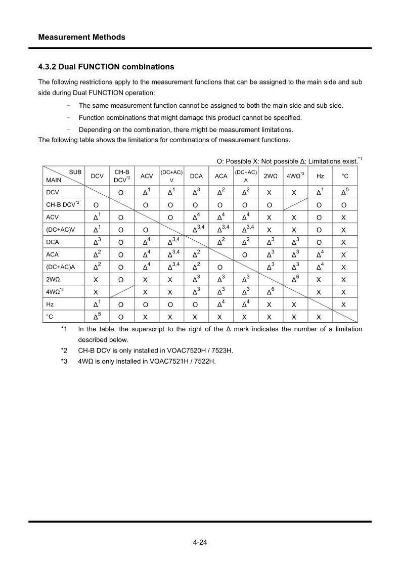
Measurement Methods
4-24
4.3.2 Dual FUNCTION combinations
The following restrictions apply to the measurement functions that can be assigned to the main side and sub side during Dual FUNCTION operation:
- The same measurement function cannot be assigned to both the main side and sub side.
- Function combinations that might damage this product cannot be specified.
- Depending on the combination, there might be measurement limitations. The following table shows the limitations for combinations of measurement functions.
O: Possible X: Not possible Δ: Limitations exist.*1 SUB
MAIN DCV
CH-B DCV*2
ACV (DC+AC)
V DCA ACA
(DC+AC)A
2WΩ 4WΩ*3 Hz °C
DCV O Δ1 Δ1 Δ3 Δ2 Δ2 X X Δ1 Δ5
CH-B DCV*2 O O O O O O O O O
ACV Δ1 O O Δ4 Δ4 Δ4 X X O X
(DC+AC)V Δ1 O O Δ3,4 Δ3,4 Δ3,4 X X O X
DCA Δ3 O Δ4 Δ3,4 Δ2 Δ2 Δ3 Δ3 O X
ACA Δ2 O Δ4 Δ3,4 Δ2 O Δ3 Δ3 Δ4 X
(DC+AC)A Δ2 O Δ4 Δ3,4 Δ2 O Δ3 Δ3 Δ4 X
2WΩ X O X X Δ3 Δ3 Δ3 Δ6 X X
4WΩ*3 X X X Δ3 Δ3 Δ3 Δ6 X X
Hz Δ1 O O O O Δ4 Δ4 X X X
°C Δ5 O X X X X X X X X
*1 In the table, the superscript to the right of the Δ mark indicates the number of a limitation described below.
*2 CH-B DCV is only installed in VOAC7520H / 7523H. *3 4WΩ is only installed in VOAC7521H / 7522H.

Measurement Methods
4-25
CAUTION!! Limitations on the Dual FUNCTION 1) The sampling rate slows down without any relation to the rate setting of SLOW/MID/FAST because it is
necessary to wait for the internal circuit to stabilize when the function is switched. 2) When performing measurement by using the Dual FUNCTION combination DCV and ACV (or (DC+AC)V)
and using the V pin and LO pin as shared input pins, the DCV accuracy is affected by the rejection performance (NMRR) for the ACV included in the measured signal. Therefore, for a FAST sample that does not have rejection or a measured signal other than that of the power supply frequency, measurement is not stable and the accuracy is not guaranteed.
Using the Dual FUNCTION combination ACV and (DC+AC)V is effective for measuring such signals or performing measurement when the AC component is dominant.
3) When performing measurement by using the Dual FUNCTION combination DCA and ACA (or (DC+AC)A) and using the mA pin or 10A pin and LO pin as shared input pins, the DCA accuracy is determined by the rejection performance (NMRR) for the ACA included in the measured signal. Therefore, for a FAST sample that does not have rejection or a measured signal other than that of the power supply frequency, measurement is not stable and the accuracy is not guaranteed.
Using the Dual FUNCTION combination ACA and (DC+AC)A is effective for measuring such signals or performing measurement when the AC component is dominant.
4) When using Dual FUNCTION to measure the voltage (or two-wire resistance) and current by using the V (or Ω) pin, mA or 10A pin, and LO pin as input pins, the voltage drop due to the measured current flowing through the LO wire affects the accuracy of the voltage (or resistance) measurement.
The (measured current) (Rt + r) (V) is added to the voltage measurement error, where Rt is the resistance of the test lead connected to the LO pin, and r is the resistance of the device-internal wiring for the LO pin (up to 30 mΩ).
For two-wire resistance measurement, (measured current) (Rt + r)/1 μV (count) is added to the resistance measurement error in only the 50 Ω range for 2WΩ, and (measured current) (Rt + r)/10 μV (count) is added in other ranges that include Lo-Ω. Here, count is the minimum resolution in the resistance range. In addition, for measurement using the Dual FUNCTION combination 4WΩ and DCA, there is no error addition if the measured current is stable, but, if DCA constantly changes, the measured value changes within the specified error range.
Note that the polarity of the voltage (or resistance) measurement error is reversed if the measured current is DCA.
If there is little change in the measured current, the REL calculation for the voltage (or resistance) function is effective.
If the measured current is ACA, the error is determined by the rejection performance (NMRR). Therefore, for a FAST sample that does not have rejection or a measured signal other than that of the
power supply frequency, measurement is not stable and the accuracy is not guaranteed.
Measurement Methods
4-26
5) When using Dual FUNCTION to measure the alternating voltage and current by using the V (or Ω) pin, mA or 10A pin, and LO pin as input pins, interference affects the accuracy of alternating current and direct current measurements.
Assuming that ACV (or (DC+AC)V) is a sine wave, Hz is the frequency, and V is the effective voltage value:
① For ACA (or (DC+AC)V), an error of Hz x V/100 + 500 (count) is added. Here, count is the minimum resolution in the ACA range. Note that, if there is only a connection and no
Dual FUNCTION operation, the error is Hz V/100 (count). ② For DCA, an error of ±20 (count) is added for frequencies up to 1 kHz. The effects of ACV
measurement on DCA at frequencies over 1 kHz are not guaranteed. 6) For the Dual FUNCTION combination DCV and °C, the thermocouple electromotive force measured by
DCV and the temperature measured by °C are simultaneously displayed, and the measured target is the same for both.
For the VOAC7520H/7523H combination CH-B DCV and °C, it is possible to simultaneously measure the DCV and temperature for different locations.
7) If using the Dual FUNCTION combination 2WΩ and 4WΩ for the VOAC7521H/7522H, the measured resistance is the same for both. It is possible to compare the effects of test lead wiring and contact resistance.
8) The internal relay switches during Dual FUNCTION operation. If using Dual FUNCTION for a long time, be careful not to shorten the interval more than necessary. Note that the relay is a consumable and that replacing it must be paid for. The approximate life of the relay is as follows.
If the relay has an expected life of 10 million switches when used in the ideal range and the interval is one second:
・If the product is used eight hours a day, 20 days a month: Approximately 17 months
・If the product is used continuously: Approximately four months However, the relay does not operate for the following combinations: DCV and DCA, DCV and ACA, CH-B DCV and DCV, CH-B DCV and DCA, CH-B DCV and ACA, or CH-B
DCV and °C (CH-B DCV is only installed in the VOAC7520H/7523H.)
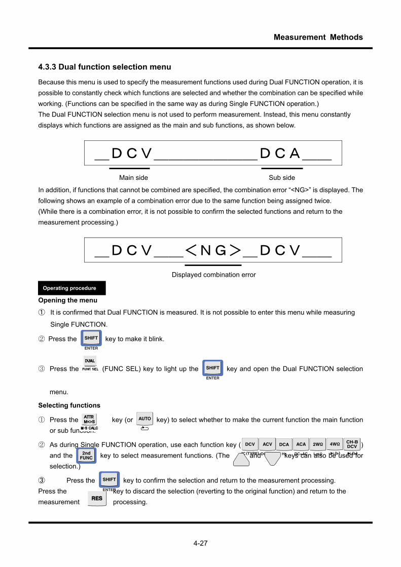
Measurement Methods
4-27
4.3.3 Dual function selection menu
Because this menu is used to specify the measurement functions used during Dual FUNCTION operation, it is possible to constantly check which functions are selected and whether the combination can be specified while working. (Functions can be specified in the same way as during Single FUNCTION operation.) The Dual FUNCTION selection menu is not used to perform measurement. Instead, this menu constantly displays which functions are assigned as the main and sub functions, as shown below.
_DCV_______DCA__ Main side Sub side
In addition, if functions that cannot be combined are specified, the combination error “<NG>” is displayed. The following shows an example of a combination error due to the same function being assigned twice. (While there is a combination error, it is not possible to confirm the selected functions and return to the measurement processing.)
_DCV__<NG>_DCV__ Displayed combination error
Opening the menu
① It is confirmed that Dual FUNCTION is measured. It is not possible to enter this menu while measuring
Single FUNCTION.
② Press the key to make it blink.
③ Press the (FUNC SEL) key to light up the key and open the Dual FUNCTION selection
menu.
Selecting functions
① Press the key (or key) to select whether to make the current function the main function or sub function.
② As during Single FUNCTION operation, use each function key ( ) and the
key to select measurement functions. (The and keys can also be used for
selection.)
③ Press the key to confirm the selection and return to the measurement processing. Press the key to discard the selection (reverting to the original function) and return to the measurement processing.
Operating procedure

Measurement Methods
4-28
4.3.4 Performing calculations using the main and sub Dual FUNCTION
During Dual FUNCTION operation, it is possible to perform arithmetic calculations on the values displayed on
the main-function and sub-function sides and then display the result on the sub-function side.
① Press the key to make it blink.
② Press the key. ChCALC=OFF is displayed.
③ Press the or key to select Main*Sub,
Main/Sub, Main+Sub, or Main-Sub.
④ Press the (ENTER) key to confirm the
setting.
CAUTION!! The results of Dual FUNCTION calculations can only be displayed. These results cannot be saved or output
to a remote location. (However, the normal measurement results obtained using the sub function can be
saved or output to a remote location.)
Dual FUNCTION calculations use the results of scaling, decibel, and relative value calculations performed for
each function.
If the main or sub function has any of the following statuses, the result of performing a Dual FUNCTION
calculation has the same status:
・ Measurement value overload
・ The number of samples for moving average calculations has not been reached.
・ Scaling calculation overflow
・ Log (0) error In a decibel calculation
Operating procedure
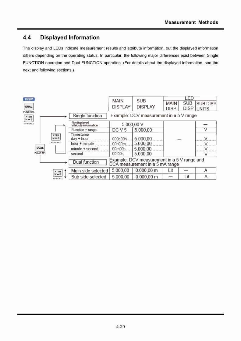
Measurement Methods
4-29
4.4 Displayed Information
The display and LEDs indicate measurement results and attribute information, but the displayed information
differs depending on the operating status. In particular, the following major differences exist between Single
FUNCTION operation and Dual FUNCTION operation. (For details about the displayed information, see the
next and following sections.)
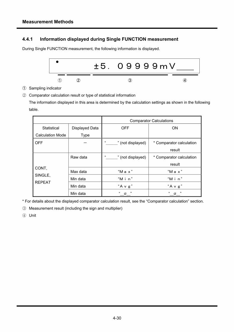
Measurement Methods
4-30
4.4.1 Information displayed during Single FUNCTION measurement
During Single FUNCTION measurement, the following information is displayed.
±5.09999mV__ ① ② ③ ④
① Sampling indicator
② Comparator calculation result or type of statistical information
The information displayed in this area is determined by the calculation settings as shown in the following
table.
Comparator Calculations
Statistical
Calculation Mode
Displayed Data
Type
OFF ON
OFF - “___” (not displayed) * Comparator calculation
result
Raw data “___” (not displayed) * Comparator calculation
result
Max data “Max” “Max”
Min data “Min” “Min”
Min data “Avg” “Avg”
CONT,
SINGLE,
REPEAT
Min data “_σ_” “_σ_”
* For details about the displayed comparator calculation result, see the “Comparator calculation” section.
③ Measurement result (including the sign and multiplier)
④ Unit
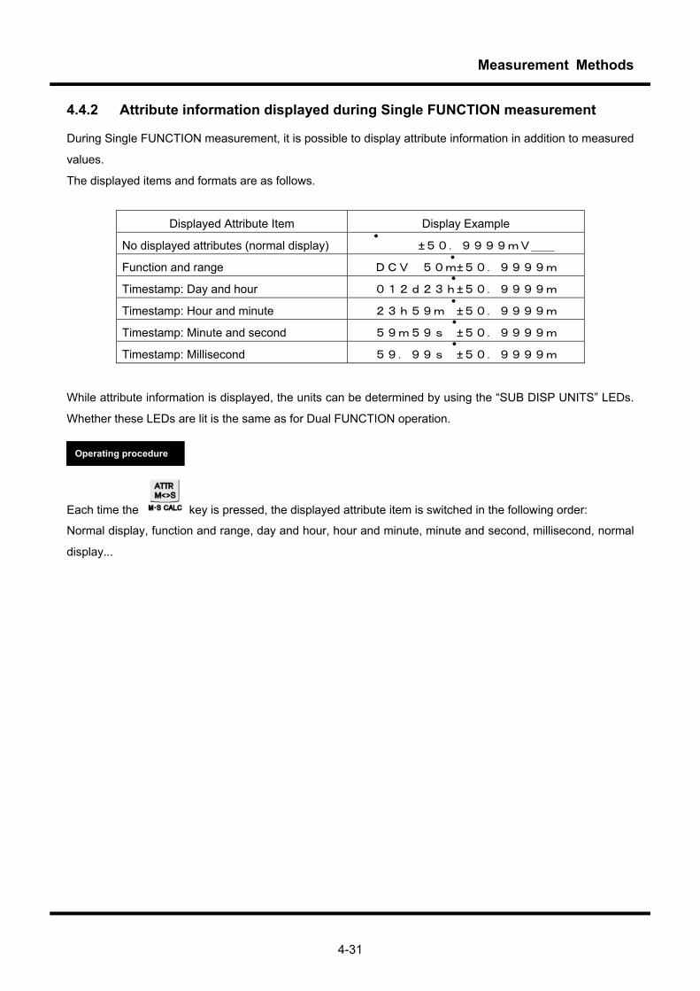
Measurement Methods
4-31
4.4.2 Attribute information displayed during Single FUNCTION measurement
During Single FUNCTION measurement, it is possible to display attribute information in addition to measured
values.
The displayed items and formats are as follows.
Displayed Attribute Item Display Example
No displayed attributes (normal display) ±50.9999mV__
Function and range DCV 50m±50.9999m
Timestamp: Day and hour 012d23h±50.9999m
Timestamp: Hour and minute 23h59m ±50.9999m
Timestamp: Minute and second 59m59s ±50.9999m
Timestamp: Millisecond 59.99s ±50.9999m
While attribute information is displayed, the units can be determined by using the “SUB DISP UNITS” LEDs.
Whether these LEDs are lit is the same as for Dual FUNCTION operation.
Each time the key is pressed, the displayed attribute item is switched in the following order:
Normal display, function and range, day and hour, hour and minute, minute and second, millisecond, normal
display...
Operating procedure
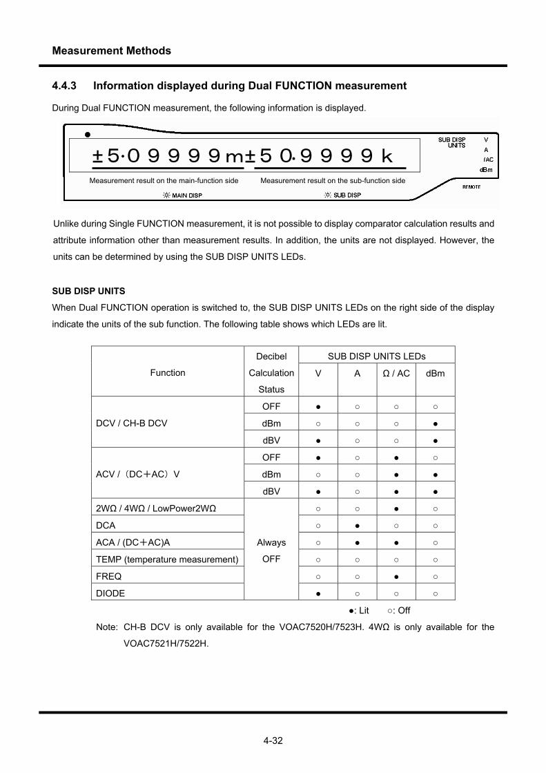
Measurement Methods
4-32
4.4.3 Information displayed during Dual FUNCTION measurement
During Dual FUNCTION measurement, the following information is displayed.
Unlike during Single FUNCTION measurement, it is not possible to display comparator calculation results and
attribute information other than measurement results. In addition, the units are not displayed. However, the
units can be determined by using the SUB DISP UNITS LEDs.
SUB DISP UNITS
When Dual FUNCTION operation is switched to, the SUB DISP UNITS LEDs on the right side of the display
indicate the units of the sub function. The following table shows which LEDs are lit.
SUB DISP UNITS LEDs
Function
Decibel
Calculation
Status
V A Ω / AC dBm
OFF
dBm DCV / CH-B DCV
dBV
OFF
dBm ACV /(DC+AC)V
dBV
2WΩ / 4WΩ / LowPower2WΩ
DCA
ACA / (DC+AC)A
TEMP (temperature measurement)
FREQ
DIODE
Always
OFF
: Lit : Off
Note: CH-B DCV is only available for the VOAC7520H/7523H. 4WΩ is only available for the
VOAC7521H/7522H.
±509999m±509999k Measurement result on the main-function side Measurement result on the sub-function side
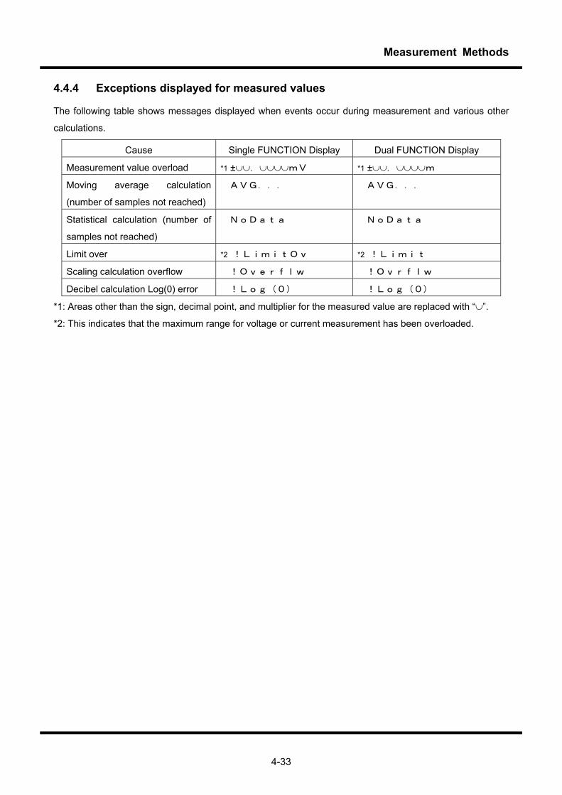
Measurement Methods
4-33
4.4.4 Exceptions displayed for measured values
The following table shows messages displayed when events occur during measurement and various other
calculations.
*1: Areas other than the sign, decimal point, and multiplier for the measured value are replaced with “∪”.
*2: This indicates that the maximum range for voltage or current measurement has been overloaded.
Cause Single FUNCTION Display Dual FUNCTION Display
Measurement value overload *1 ±∪∪.∪∪∪∪mV *1 ±∪∪.∪∪∪∪m
Moving average calculation
(number of samples not reached)
AVG... AVG...
Statistical calculation (number of
samples not reached)
NoData NoData
Limit over *2 !LimitOv *2 !Limit
Scaling calculation overflow !Overflw !Ovrflw
Decibel calculation Log(0) error !Log(0) !Log(0)

Measurement Methods
4-34
INTERVAL=3,600sec
4.5 Setting and changing sampling (SAMPLE) 4.5.1 Setting the sample rate (RATE)
The sample rate is the measurement cycle. Three levels can be selected: SLOW, MID and FAST. Stipulation of the sample rate differs according to the function. In addition, the measurement resolution may vary according to the sample rate. The sample rate setting is shared by all functions. Setting the sample rate
① By pressing the key during a measurement, the sample rate changes from SLOW to MID to
FAST (then back to SLOW).
When changing the sample rate, the sample rate setting is temporarily displayed.
4.5.2 Setting the measurement interval (INT)
Measurement intervals can be measured over long cycles of one second or longer. INT is used when saving lengthy logging data to the multimeter. Setting the measurement interval
① Press the key so that it flashes.
② Press the (INT) key.
③ Use the , and range keys to specify the measurement interval.
CAUTION! The measurement resolution is not related to the setting of the interval time. It depends on the sample rate setting. When the standard measurement cycle for Dual FUNCTION operations and slow frequency measurements, etc., is longer than the cycle specified by the interval time, the interval time will disregarded.
Operating procedure
Operating procedure
Digit shifts with each press
Measure numeric value

Measurement Methods
4-35
4.5.3 Switching between free run and hold (HOLD/TRIG and RES)
A free run operation is an operation in which measurements are repeatedly performed at cycles set according to the sampling rate and interval time. On the other hand, a hold operation is an operation in which the multimeter initiates a measurement when it receives a trigger. Changes in the free run/hold status during a measurement
Free run Hold
HOLD
RES
Completion of calculation in SINGLE measured value statistics mode
HOLD
One time measurement
*When the AVG calculation is on, n measurements will be taken. The HOLD key will turn off during the measurements. Trigger A trigger is an event that initiates a measurement during a hold operation. There are three causes of triggers, as shown below.
Trigger cause Operation
Manual trigger (TRIG) key is pressed during a hold operation
Remote trigger In remote mode, the address command is GET (GPIB only), while the remote command is *TRG or :MEAS?
External trigger A signal is applied from the TRIG terminal of the DIO unit (optional)
All triggers are disregarded during a free run operation. Triggers are also disregarded during a hold operation
until the previously triggered measurement has been completed. A trigger can be accepted when the
(TRIG) key is on.
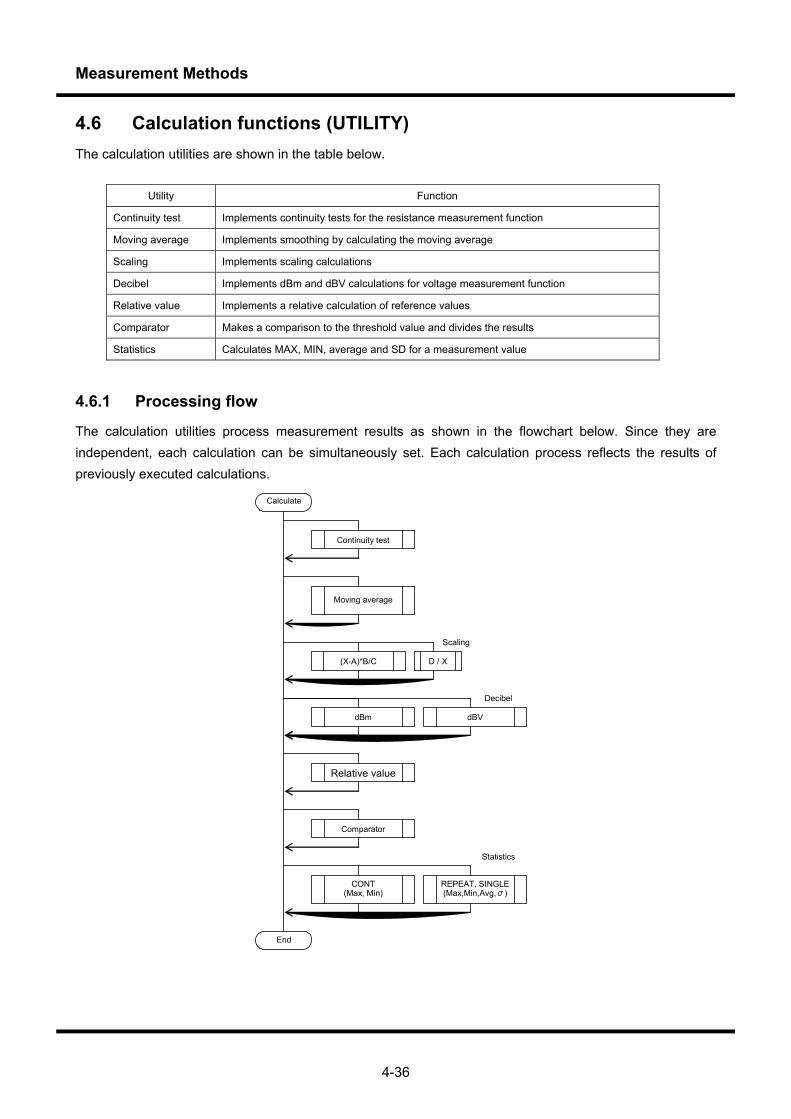
Measurement Methods
4-36
4.6 Calculation functions (UTILITY) The calculation utilities are shown in the table below.
Utility Function
Continuity test Implements continuity tests for the resistance measurement function
Moving average Implements smoothing by calculating the moving average
Scaling Implements scaling calculations
Decibel Implements dBm and dBV calculations for voltage measurement function
Relative value Implements a relative calculation of reference values
Comparator Makes a comparison to the threshold value and divides the results
Statistics Calculates MAX, MIN, average and SD for a measurement value
4.6.1 Processing flow
The calculation utilities process measurement results as shown in the flowchart below. Since they are independent, each calculation can be simultaneously set. Each calculation process reflects the results of previously executed calculations.
Calculate
Moving average
Relative value
(X-A)*B/C D / X
dBm
Comparator
End
REPEAT, SINGLE(Max,Min,Avg,σ)
CONT (Max, Min)
Scaling
Decibel
Statistics
Continuity test
dBV
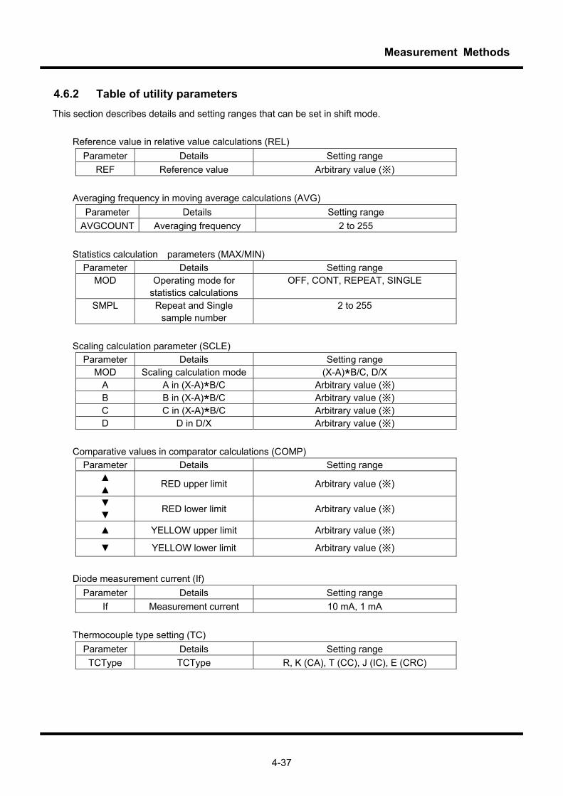
Measurement Methods
4-37
4.6.2 Table of utility parameters This section describes details and setting ranges that can be set in shift mode.
Reference value in relative value calculations (REL) Parameter Details Setting range
REF Reference value Arbitrary value (※)
Averaging frequency in moving average calculations (AVG) Parameter Details Setting range
AVGCOUNT Averaging frequency 2 to 255
Statistics calculation parameters (MAX/MIN) Parameter Details Setting range
MOD Operating mode for statistics calculations
OFF, CONT, REPEAT, SINGLE
SMPL Repeat and Single sample number
2 to 255
Scaling calculation parameter (SCLE)
Parameter Details Setting range MOD Scaling calculation mode (X-A)*B/C, D/X
A A in (X-A)*B/C Arbitrary value (※) B B in (X-A)*B/C Arbitrary value (※) C C in (X-A)*B/C Arbitrary value (※) D D in D/X Arbitrary value (※)
Comparative values in comparator calculations (COMP)
Parameter Details Setting range RED upper limit Arbitrary value (※)
RED lower limit Arbitrary value (※)
YELLOW upper limit Arbitrary value (※)
YELLOW lower limit Arbitrary value (※)
Diode measurement current (If)
Parameter Details Setting range If Measurement current 10 mA, 1 mA
Thermocouple type setting (TC)
Parameter Details Setting range TCType TCType R, K (CA), T (CC), J (IC), E (CRC)

Measurement Methods
4-38
Decibel calculation parameters (dBV, dBm) Parameter Details Setting range
MOD Decibel calculation mode dBm, dBV
dBm-Ref Reference resistance value in dBm calculations
4, 8, 16, 32, 50, 75, 93, 110, 125, 135, 150, 200, 250, 300, 500, 600, 800, 900, 1000,
1200, 8000
dBV-Ref Reference voltage in dBV calculations
1.0μV, 1.0mV, 1.0V
Interval time (INT)
Parameter details Setting range INT Interval time 0 to 3, 600sec (However, 0 sec is free run)
Continuity test threshold resistance (Rth)
Parameter Details Setting range R-THRSLD Threshold resistance 1.0 to 5, 000.0Ω (0.1Ω increments)
Calculation configuration between Dual FUNCTION (STYLE)
Parameter Details Setting range
ChCALC Calculation mode between Dual FUNCTION
OFF, “Main*Sub”, “Main/Sub”, “Main+Sub”, “Main-Sub”
※Configuring arbitrary value parameters The arbitrary values used in parameters for relative value calculations, scaling calculations and comparator calculation are as follows. ・ Display format
±999.999k
Sign Mantissa Exponent
Sign: positive or negative Mantissa: Numeric value consisting of 6
valid digits Exponent: exponent displayed according to
multiplier and position of decimal point
・ Sign
The sign can either be + or -. Align the cursor with the sign using the key and use the and
keys to change the sign. Note that when the mantissa is 0, the sign is fixed to +.
・ Mantissa The valid number of digits in the mantissa is six. Exponents of 10 are displayed as K (103) and M (106). Place
the cursor next to the digit you want to change using the key and then press the and
keys to increase/decrease the value of the digit by one. Digits can be increased or decreased as needed.
However, if the permissible range (excluding the decimal point), 000000 to 999999, is exceeded as a result of
increasing/decreasing the numeric value, the key operation will be disregarded.
Exponent of 10 (determined by the multiplier and decimal place position)
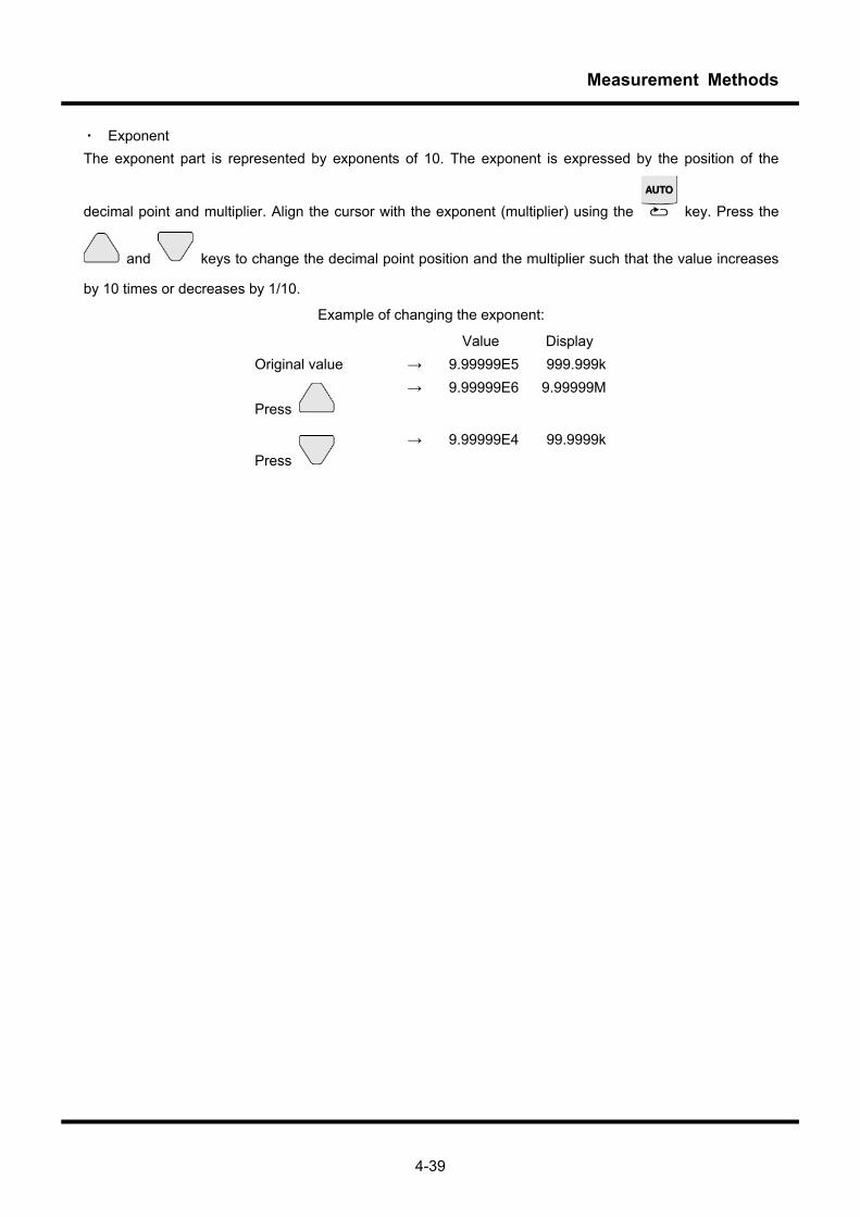
Measurement Methods
4-39
・ Exponent The exponent part is represented by exponents of 10. The exponent is expressed by the position of the
decimal point and multiplier. Align the cursor with the exponent (multiplier) using the key. Press the
and keys to change the decimal point position and the multiplier such that the value increases
by 10 times or decreases by 1/10.
Example of changing the exponent:
Value Display Original value → 9.99999E5 999.999k
Press → 9.99999E6 9.99999M
Press → 9.99999E4 99.9999k
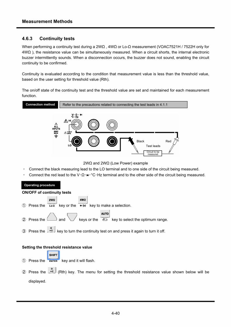
Measurement Methods
4-40
4.6.3 Continuity tests When performing a continuity test during a 2WΩ , 4WΩ or Lo-Ω measurement (VOAC7521H / 7522H only for 4WΩ ), the resistance value can be simultaneously measured. When a circuit shorts, the internal electronic buzzer intermittently sounds. When a disconnection occurs, the buzzer does not sound, enabling the circuit continuity to be confirmed. Continuity is evaluated according to the condition that measurement value is less than the threshold value, based on the user setting for threshold value (Rth). The on/off state of the continuity test and the threshold value are set and maintained for each measurement function.
2WΩ and 2WΩ (Low Power) example ・ Connect the black measuring lead to the LO terminal and to one side of the circuit being measured. ・ Connect the red lead to the V・Ω・ ・°C・Hz terminal and to the other side of the circuit being measured. ON/OFF of continuity tests
① Press the key or the key to make a selection.
② Press the and keys or the key to select the optimum range.
③ Press the key to turn the continuity test on and press it again to turn it off.
Setting the threshold resistance value
① Press the key and it will flash.
② Press the (Rth) key. The menu for setting the threshold resistance value shown below will be
displayed.
Refer to the precautions related to connecting the test leads in 4.1.1 Connection method
Operating procedure
Test leads
Circuit to be measured
Black Red
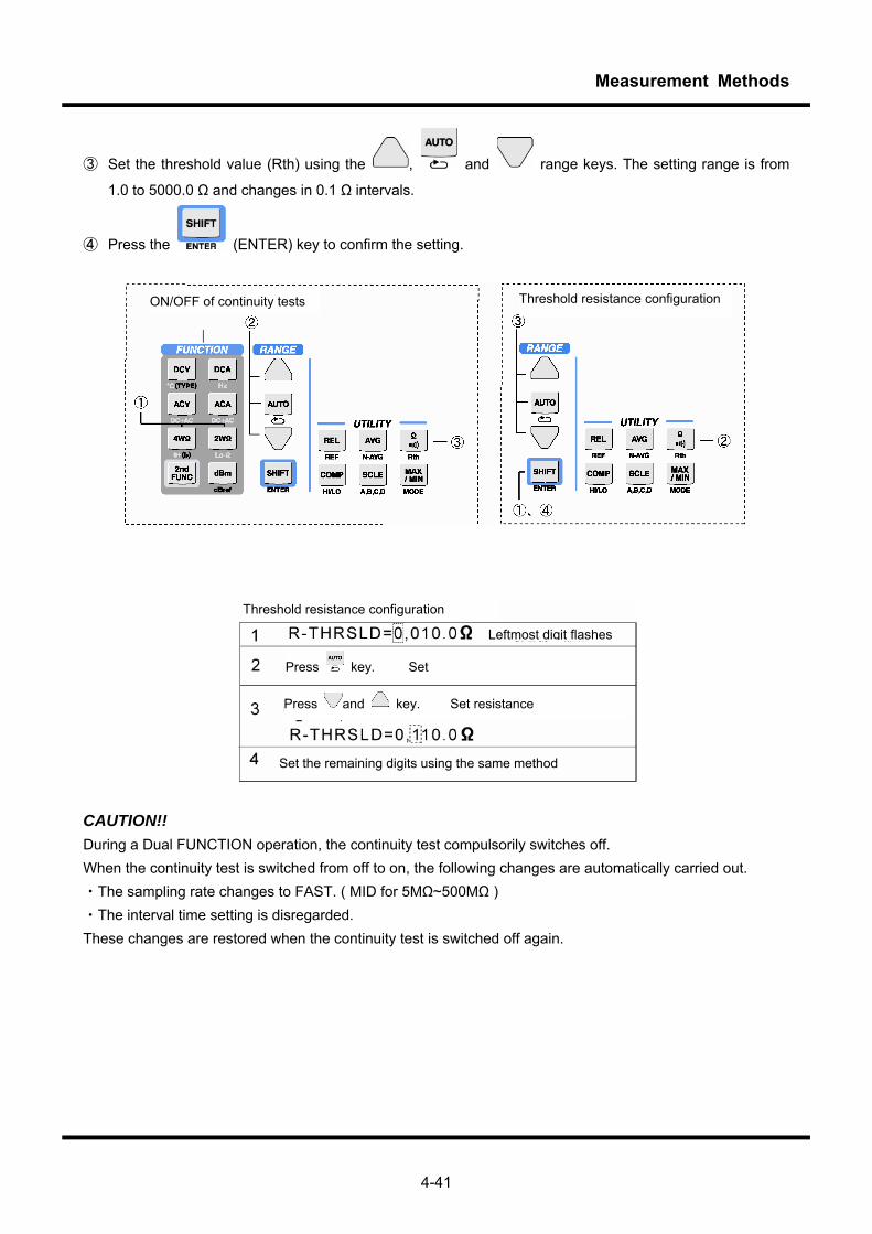
Measurement Methods
4-41
③ Set the threshold value (Rth) using the , and range keys. The setting range is from
1.0 to 5000.0 Ω and changes in 0.1 Ω intervals.
④ Press the (ENTER) key to confirm the setting.
CAUTION!! During a Dual FUNCTION operation, the continuity test compulsorily switches off. When the continuity test is switched from off to on, the following changes are automatically carried out. ・The sampling rate changes to FAST. ( MID for 5MΩ~500MΩ ) ・The interval time setting is disregarded. These changes are restored when the continuity test is switched off again.
ON/OFF of continuity tests Threshold resistance configuration
Threshold resistance configuration
Leftmost digit flashes
Press and key. Set resistance
Set the remaining digits using the same method
Press key. Set
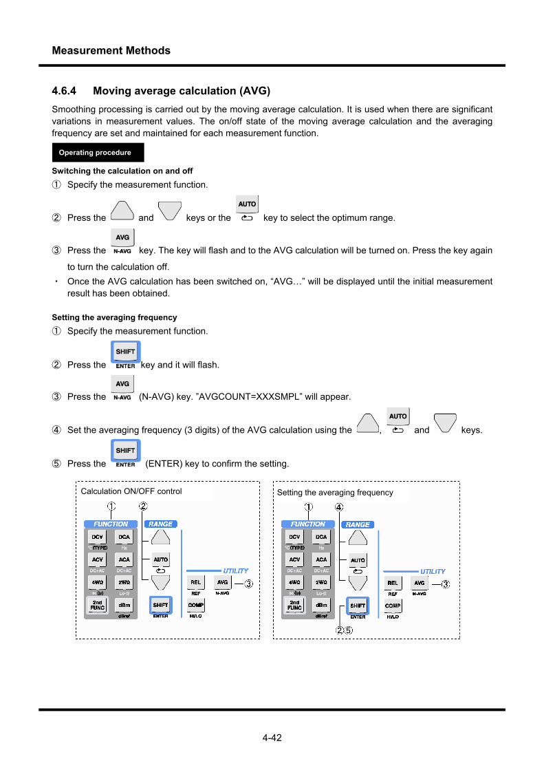
Measurement Methods
4-42
4.6.4 Moving average calculation (AVG) Smoothing processing is carried out by the moving average calculation. It is used when there are significant variations in measurement values. The on/off state of the moving average calculation and the averaging frequency are set and maintained for each measurement function. Switching the calculation on and off ① Specify the measurement function.
② Press the and keys or the key to select the optimum range.
③ Press the key. The key will flash and to the AVG calculation will be turned on. Press the key again
to turn the calculation off. ・ Once the AVG calculation has been switched on, “AVG…” will be displayed until the initial measurement
result has been obtained. Setting the averaging frequency ① Specify the measurement function.
② Press the key and it will flash.
③ Press the (N-AVG) key. ”AVGCOUNT=XXXSMPL” will appear.
④ Set the averaging frequency (3 digits) of the AVG calculation using the , and keys.
⑤ Press the (ENTER) key to confirm the setting.
Operating procedure
Setting the averaging frequency Calculation ON/OFF control
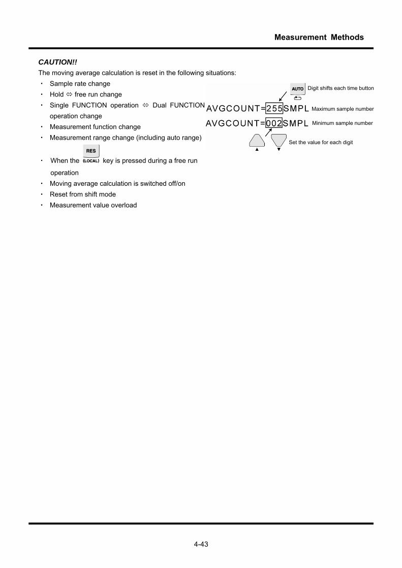
Measurement Methods
4-43
CAUTION!! The moving average calculation is reset in the following situations: ・ Sample rate change ・ Hold free run change ・ Single FUNCTION operation Dual FUNCTION
operation change ・ Measurement function change ・ Measurement range change (including auto range)
・ When the key is pressed during a free run
operation ・ Moving average calculation is switched off/on ・ Reset from shift mode ・ Measurement value overload
Digit shifts each time button
Maximum sample number
Minimum sample number
Set the value for each digit
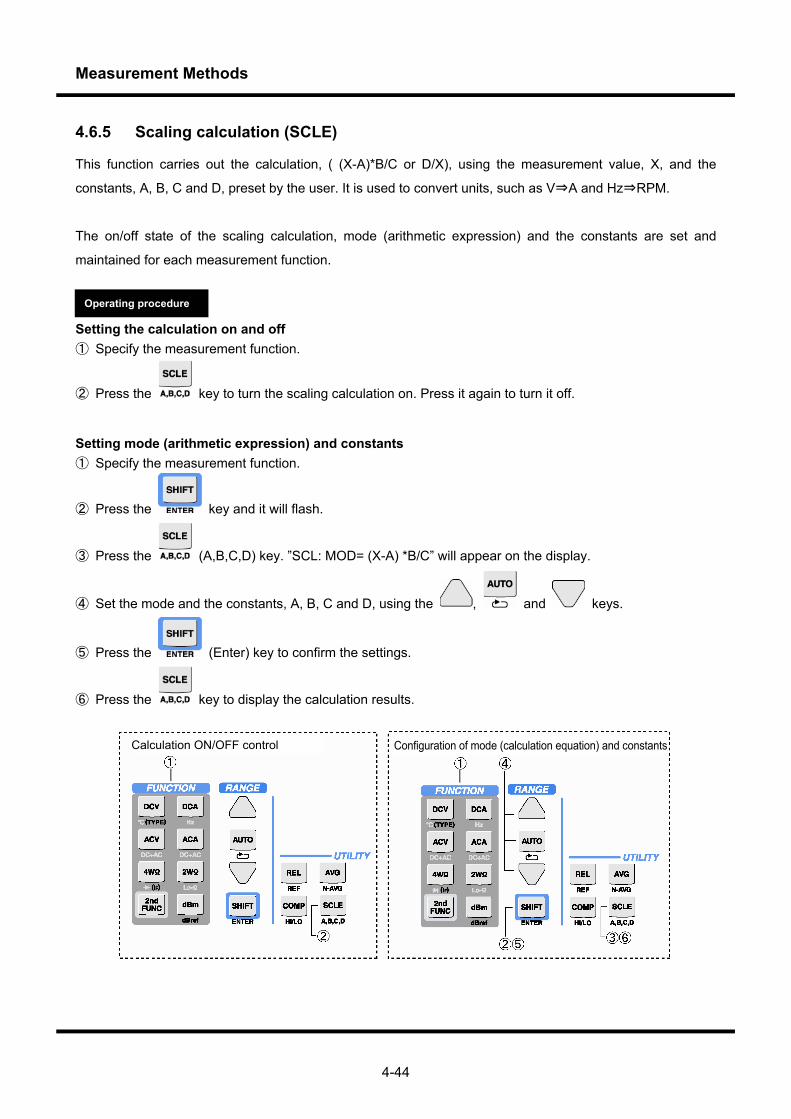
Measurement Methods
4-44
4.6.5 Scaling calculation (SCLE)
This function carries out the calculation, ( (X-A)*B/C or D/X), using the measurement value, X, and the
constants, A, B, C and D, preset by the user. It is used to convert units, such as V⇒A and Hz⇒RPM.
The on/off state of the scaling calculation, mode (arithmetic expression) and the constants are set and
maintained for each measurement function.
Setting the calculation on and off ① Specify the measurement function.
② Press the key to turn the scaling calculation on. Press it again to turn it off.
Setting mode (arithmetic expression) and constants ① Specify the measurement function.
② Press the key and it will flash.
③ Press the (A,B,C,D) key. ”SCL: MOD= (X-A) *B/C” will appear on the display.
④ Set the mode and the constants, A, B, C and D, using the , and keys.
⑤ Press the (Enter) key to confirm the settings.
⑥ Press the key to display the calculation results.
Calculation ON/OFF control Configuration of mode (calculation equation) and constants
Operating procedure
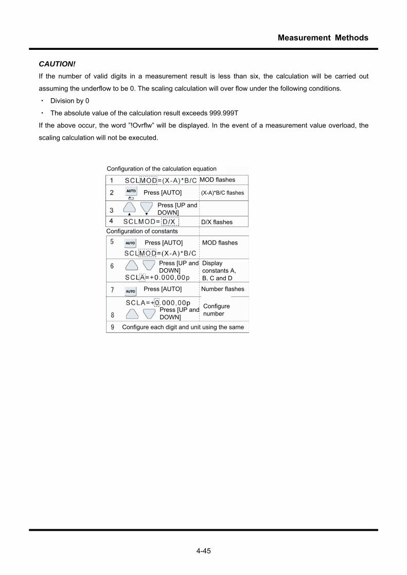
Measurement Methods
4-45
CAUTION! If the number of valid digits in a measurement result is less than six, the calculation will be carried out
assuming the underflow to be 0. The scaling calculation will over flow under the following conditions.
・ Division by 0
・ The absolute value of the calculation result exceeds 999.999T
If the above occur, the word ”!Ovrflw” will be displayed. In the event of a measurement value overload, the
scaling calculation will not be executed.
Configuration of the calculation equation
MOD flashes
Press [AUTO] (X-A)*B/C flashes
Press [UP and DOWN]
Configuration of constants D/X flashes
Press [AUTO] MOD flashes
Press [UP and DOWN]
Display constants A, B, C and D
Press [UP and DOWN]
Press [AUTO] Number flashes
Configure number
Configure each digit and unit using the same

Measurement Methods
4-46
4.6.6 Decibel calculations
The decibel calculation performs decibel conversion of measurement values for the DCV, ACV, (DC+AC) V and CH-B DCV measurement functions. The dBm calculation performs a decibel calculation of the power consumption of resistance referenced to 1 mW from the measured voltage. The dBV calculation performs a decibel calculation of the ratio between the measurement voltage and the reference voltage. The on/off state of the decibel calculation, and the calculation mode (dBm/dBV) and reference resistance/voltage are set and maintained for each measurement function. Equations:
⎟⎟⎟⎟
⎠
⎞
⎜⎜⎜⎜
⎝
⎛
××=
− ][100.1resistanceR
valueMeasured
log103
2
10W
eferencedBm
][voltageRvalueMeasured
log20V 10 VeferencedB ×=
Relative value dB By combining the decibel calculation with a relative value calculation, the decibels of the ratio to the reference value can be calculated as follows. (Also refer to the explanation on relative value calculations.)
valueREFvalueMesured
log20
voltageRvalueREF
log20voltageRvalueMesured
log20
valueREF - valueMeasured&
10
1010
×=
×−×=
=
eferenceeference
dBVdBVdBVREL )()(
Switching the calculation on and off ① Set the measurement function to voltage measurement.
② Press the key to turn the decibel calculation on and press it again to turn the calculation off.
Setting the mode (dBm/dBV) and reference value
③ Press the key and it will flash.
④ Press the (dBref) key.
Refer to operating procedures in 4.2.9, dB measurements.
Here, the following values can be selected as the reference resistance: 4, 8, 16, 32, 50, 75, 93, 110, 125, 135, 150, 200, 250, 300, 500, 600, 800, 900, 1000, 1200 and 8000 Ω
Here, the following values can be selected as the reference voltage: 1.0μV, 1.0mV and 1.0V
Operating procedure
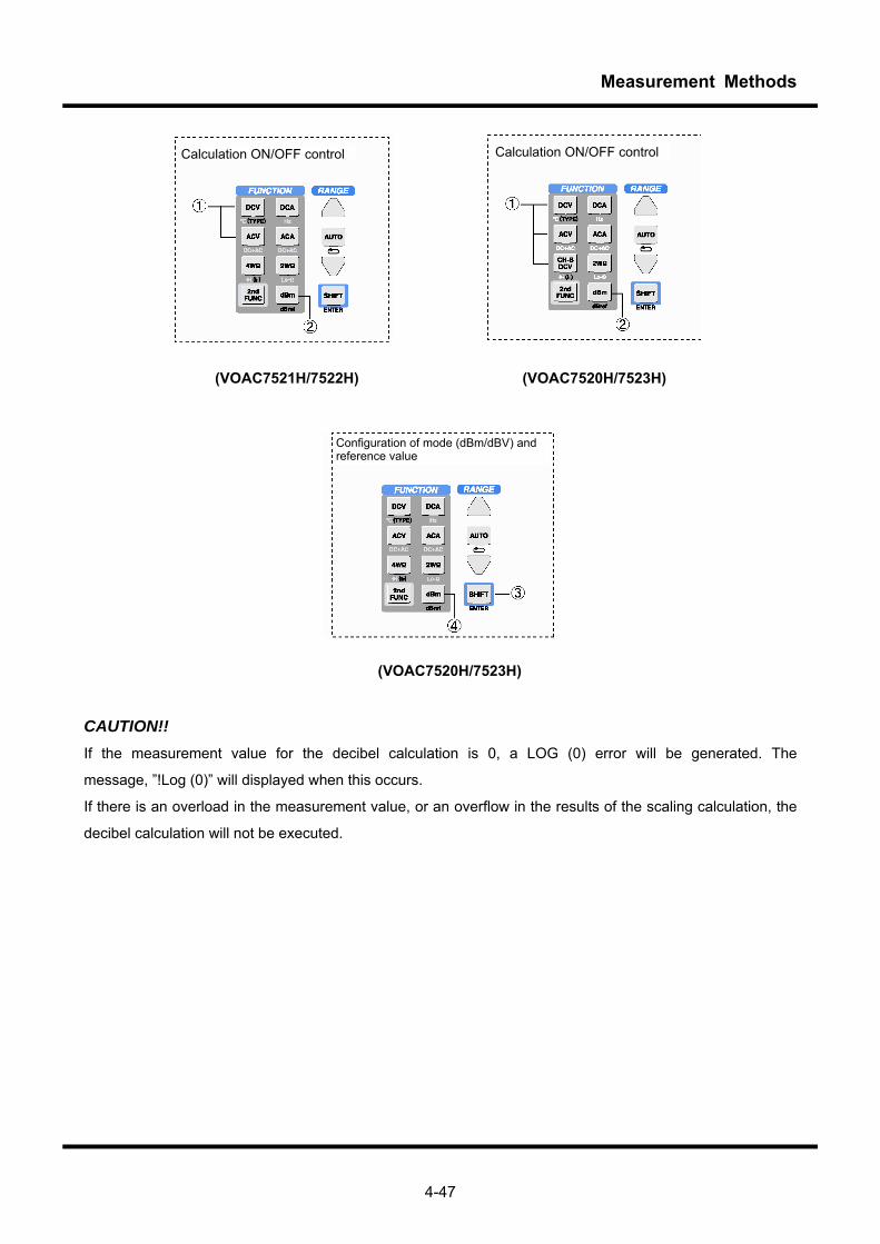
Measurement Methods
4-47
(VOAC7521H/7522H) (VOAC7520H/7523H)
(VOAC7520H/7523H)
CAUTION!! If the measurement value for the decibel calculation is 0, a LOG (0) error will be generated. The
message, ”!Log (0)” will displayed when this occurs.
If there is an overload in the measurement value, or an overflow in the results of the scaling calculation, the
decibel calculation will not be executed.
Calculation ON/OFF control
Configuration of mode (dBm/dBV) and reference value
Calculation ON/OFF control
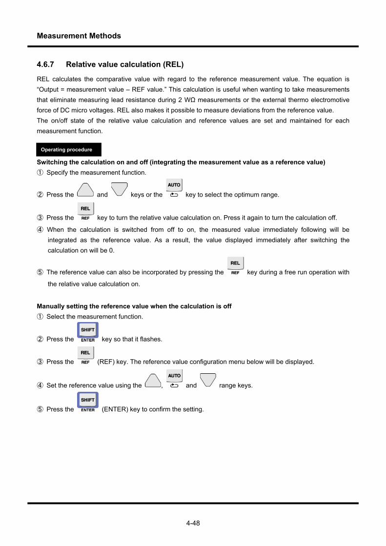
Measurement Methods
4-48
4.6.7 Relative value calculation (REL)
REL calculates the comparative value with regard to the reference measurement value. The equation is “Output = measurement value – REF value.” This calculation is useful when wanting to take measurements that eliminate measuring lead resistance during 2 WΩ measurements or the external thermo electromotive force of DC micro voltages. REL also makes it possible to measure deviations from the reference value. The on/off state of the relative value calculation and reference values are set and maintained for each measurement function. Switching the calculation on and off (integrating the measurement value as a reference value) ① Specify the measurement function.
② Press the and keys or the key to select the optimum range.
③ Press the key to turn the relative value calculation on. Press it again to turn the calculation off.
④ When the calculation is switched from off to on, the measured value immediately following will be integrated as the reference value. As a result, the value displayed immediately after switching the calculation on will be 0.
⑤ The reference value can also be incorporated by pressing the key during a free run operation with
the relative value calculation on.
Manually setting the reference value when the calculation is off ① Select the measurement function.
② Press the key so that it flashes.
③ Press the (REF) key. The reference value configuration menu below will be displayed.
④ Set the reference value using the , and range keys.
⑤ Press the (ENTER) key to confirm the setting.
Operating procedure

Measurement Methods
4-49
Y: displayed value (differential) X: measured value REF: reference value
Shift digit or unit with each key press
Set reference value or unit
CAUTION!! Even if the reference value is manually set when the relative value calculation is off, it will automatically be cleared when the relative value calculation is switched on. Erroneous data is handled as shown in the table below.
Measurement value Scaling calculation Decibel calculation Relative value
calculation output Normal Normal Normal Output the relative value
calculation result Normal Normal Log (0) error Log (0) error Normal Overflow All conditions Overflow
Overload All conditions All conditions Overload
Calculation ON/OFF control (use measured value as reference value)
Manual configuration of reference value when calculation is off.
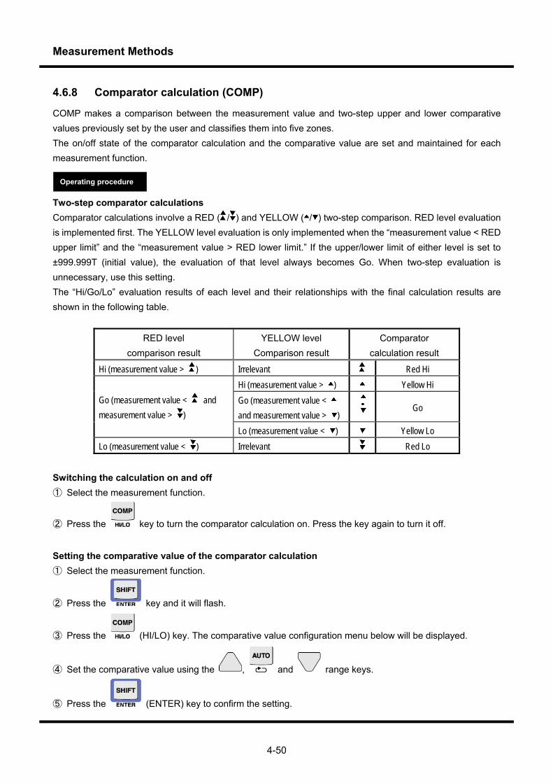
Measurement Methods
4-50
4.6.8 Comparator calculation (COMP)
COMP makes a comparison between the measurement value and two-step upper and lower comparative values previously set by the user and classifies them into five zones. The on/off state of the comparator calculation and the comparative value are set and maintained for each measurement function. Two-step comparator calculations Comparator calculations involve a RED ( / ) and YELLOW ( / ) two-step comparison. RED level evaluation is implemented first. The YELLOW level evaluation is only implemented when the “measurement value < RED upper limit” and the “measurement value > RED lower limit.” If the upper/lower limit of either level is set to ±999.999T (initial value), the evaluation of that level always becomes Go. When two-step evaluation is unnecessary, use this setting. The “Hi/Go/Lo” evaluation results of each level and their relationships with the final calculation results are shown in the following table.
RED level comparison result
YELLOW level Comparison result
Comparator calculation result
Hi (measurement value > ) Irrelevant Red Hi Hi (measurement value > ) Yellow Hi Go (measurement value < and measurement value > )
Go
Go (measurement value < and measurement value > )
Lo (measurement value < ) Yellow Lo Lo (measurement value < ) Irrelevant Red Lo
Switching the calculation on and off ① Select the measurement function.
② Press the key to turn the comparator calculation on. Press the key again to turn it off.
Setting the comparative value of the comparator calculation ① Select the measurement function.
② Press the key and it will flash.
③ Press the (HI/LO) key. The comparative value configuration menu below will be displayed.
④ Set the comparative value using the , and range keys.
⑤ Press the (ENTER) key to confirm the setting.
Operating procedure
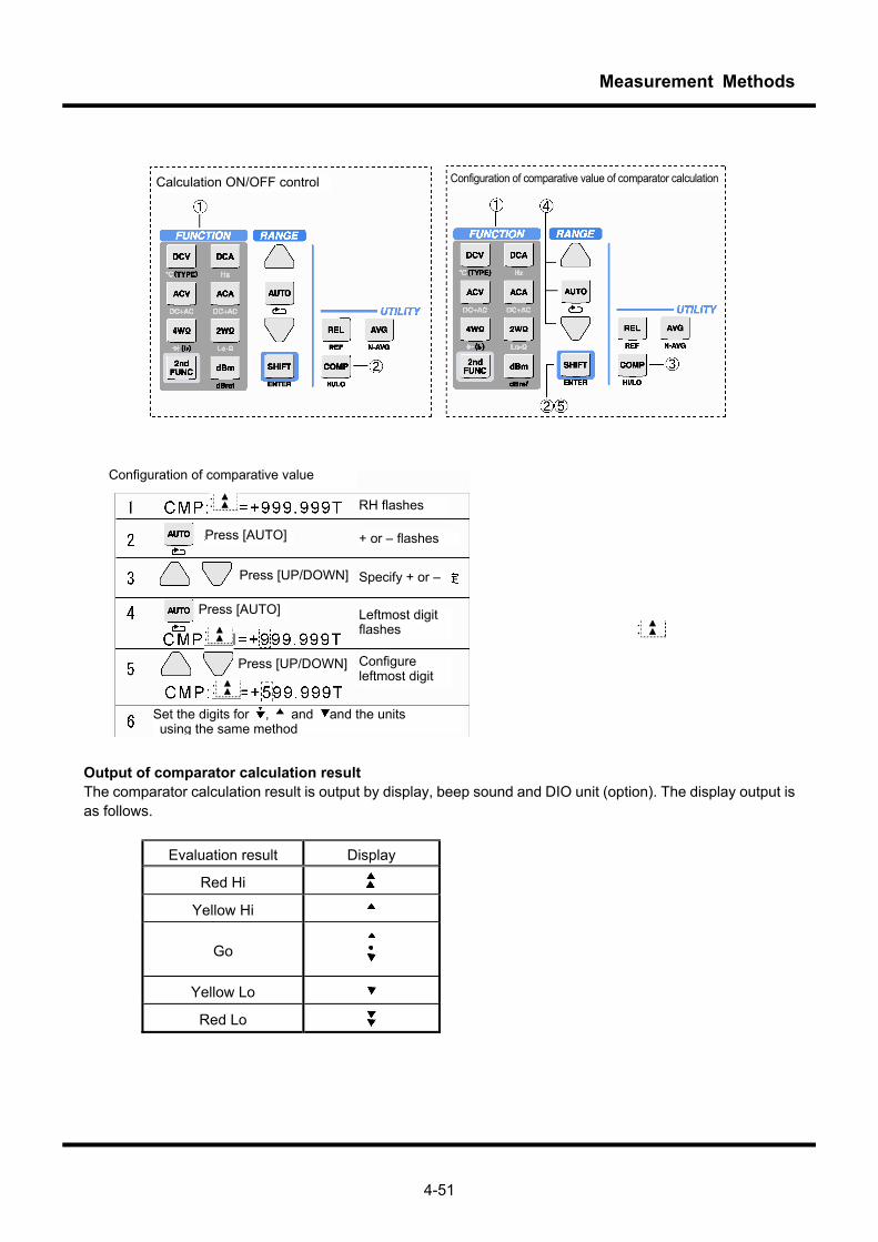
Measurement Methods
4-51
Output of comparator calculation result The comparator calculation result is output by display, beep sound and DIO unit (option). The display output is as follows.
Evaluation result Display
Red Hi
Yellow Hi
Go
Yellow Lo
Red Lo
Calculation ON/OFF control Configuration of comparative value of comparator calculation
Configuration of comparative value
Set the digits for , and and the units using the same method
RH flashes
Press [AUTO] + or – flashes
Press [UP/DOWN]
Press [AUTO]
Specify + or –
Leftmost digit flashes
Configure leftmost digit
Press [UP/DOWN]
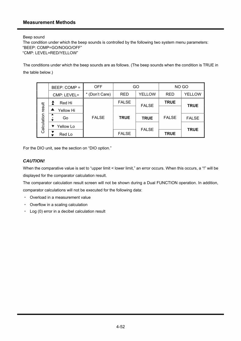
Measurement Methods
4-52
Beep sound The condition under which the beep sounds is controlled by the following two system menu parameters: “BEEP: COMP=GO/NOGO/OFF” “CMP: LEVEL=RED/YELLOW”
The conditions under which the beep sounds are as follows. (The beep sounds when the condition is TRUE in
the table below.)
BEEP: COMP = OFF GO NO GO
CMP: LEVEL= * (Don’t Care) RED YELLOW RED YELLOW
Red Hi FALSE TRUE
Yellow Hi FALSE TRUE
・ Go TRUE FALSE
Yellow Lo
TRUE FALSE
Cal
cula
tion
resu
lt
Red Lo
FALSE
FALSE FALSE
TRUE TRUE
For the DIO unit, see the section on “DIO option.” CAUTION! When the comparative value is set to “upper limit < lower limit,” an error occurs. When this occurs, a “!” will be
displayed for the comparator calculation result.
The comparator calculation result screen will not be shown during a Dual FUNCTION operation. In addition,
comparator calculations will not be executed for the following data:
・ Overload in a measurement value
・ Overflow in a scaling calculation ・ Log (0) error in a decibel calculation result
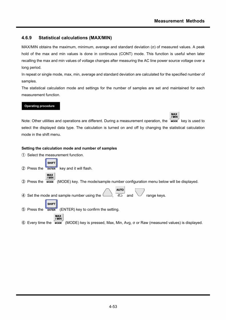
Measurement Methods
4-53
4.6.9 Statistical calculations (MAX/MIN)
MAX/MIN obtains the maximum, minimum, average and standard deviation (σ) of measured values. A peak
hold of the max and min values is done in continuous (CONT) mode. This function is useful when later
recalling the max and min values of voltage changes after measuring the AC line power source voltage over a
long period.
In repeat or single mode, max, min, average and standard deviation are calculated for the specified number of
samples.
The statistical calculation mode and settings for the number of samples are set and maintained for each
measurement function.
Note: Other utilities and operations are different. During a measurement operation, the key is used to
select the displayed data type. The calculation is turned on and off by changing the statistical calculation
mode in the shift menu.
Setting the calculation mode and number of samples
① Select the measurement function.
② Press the key and it will flash.
③ Press the (MODE) key. The mode/sample number configuration menu below will be displayed.
④ Set the mode and sample number using the , and range keys.
⑤ Press the (ENTER) key to confirm the setting.
⑥ Every time the (MODE) key is pressed, Max, Min, Avg, σ or Raw (measured values) is displayed.
Operating procedure
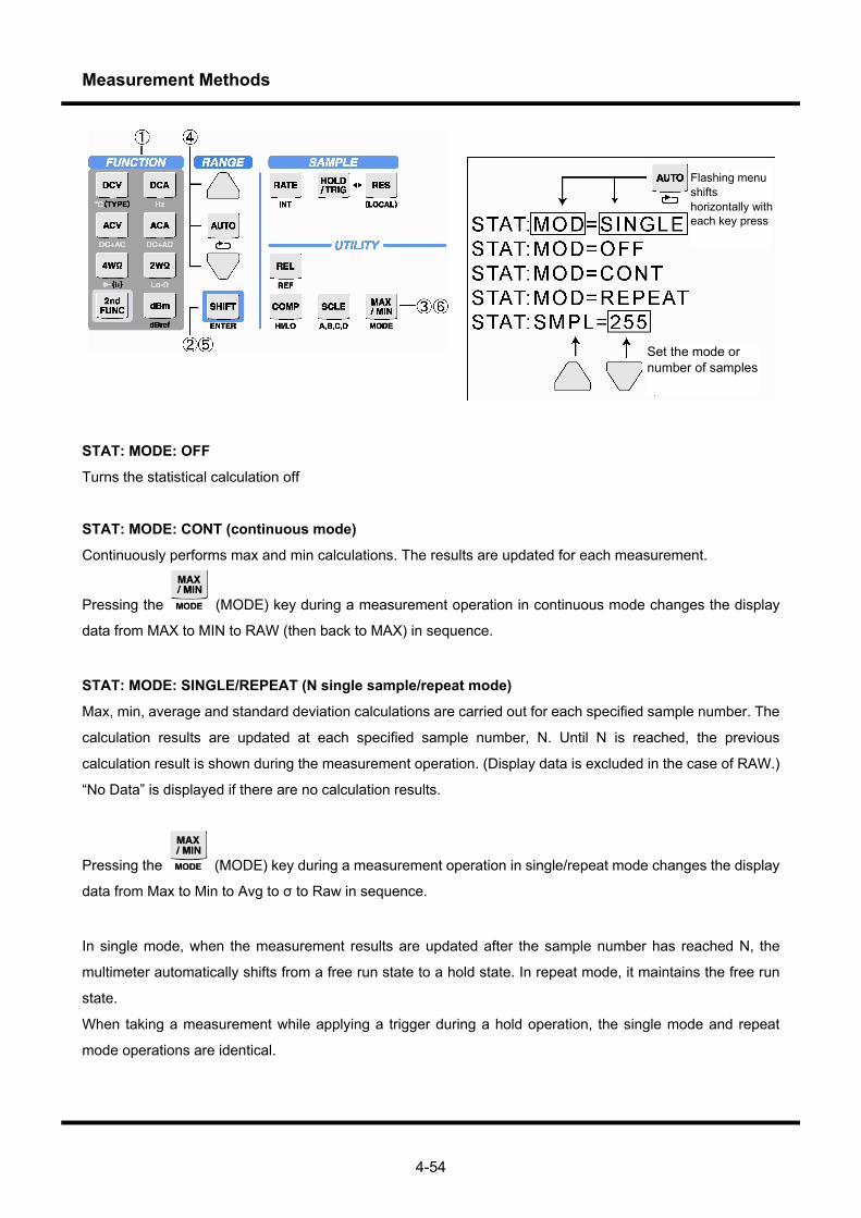
Measurement Methods
4-54
Flashing menu shifts horizontally with each key press
Set the mode or number of samples
STAT: MODE: OFF
Turns the statistical calculation off
STAT: MODE: CONT (continuous mode)
Continuously performs max and min calculations. The results are updated for each measurement.
Pressing the (MODE) key during a measurement operation in continuous mode changes the display
data from MAX to MIN to RAW (then back to MAX) in sequence.
STAT: MODE: SINGLE/REPEAT (N single sample/repeat mode)
Max, min, average and standard deviation calculations are carried out for each specified sample number. The
calculation results are updated at each specified sample number, N. Until N is reached, the previous
calculation result is shown during the measurement operation. (Display data is excluded in the case of RAW.)
“No Data” is displayed if there are no calculation results.
Pressing the (MODE) key during a measurement operation in single/repeat mode changes the display
data from Max to Min to Avg to σ to Raw in sequence.
In single mode, when the measurement results are updated after the sample number has reached N, the
multimeter automatically shifts from a free run state to a hold state. In repeat mode, it maintains the free run
state.
When taking a measurement while applying a trigger during a hold operation, the single mode and repeat
mode operations are identical.
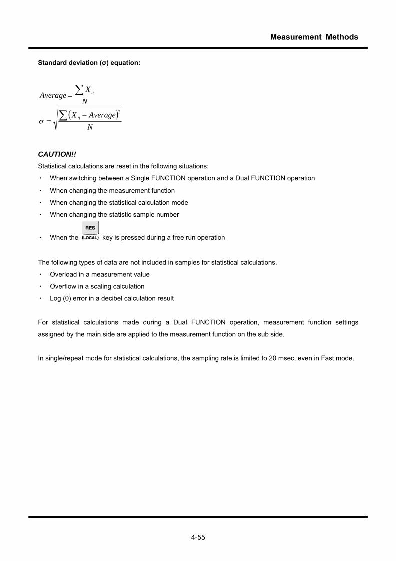
Measurement Methods
4-55
Standard deviation (σ) equation:
( )NAverageX
NX
Average
n
n
∑
∑
−=
=
2
σ
CAUTION!! Statistical calculations are reset in the following situations:
・ When switching between a Single FUNCTION operation and a Dual FUNCTION operation
・ When changing the measurement function
・ When changing the statistical calculation mode
・ When changing the statistic sample number
・ When the key is pressed during a free run operation
The following types of data are not included in samples for statistical calculations.
・ Overload in a measurement value
・ Overflow in a scaling calculation
・ Log (0) error in a decibel calculation result
For statistical calculations made during a Dual FUNCTION operation, measurement function settings
assigned by the main side are applied to the measurement function on the sub side.
In single/repeat mode for statistical calculations, the sampling rate is limited to 20 msec, even in Fast mode.

Measurement Methods
4-56
4.7 Saving and recalling setup (SETUP) SETUP saves and recalls the panel setup. It also returns the panel setup to the factory settings by resetting them. Saving the setup Saving the current panel setup to internal memory.
① Press the key and it will flash and the key will light up.
② Press the key and select Save: # n [Shft].
③ Set the save memory number using the , and range keys. (The setup can be saved
in the range #1 to #10.)
④ Press the (ENTER) key. Save? Y: ↓ N: ↑ will be displayed.
⑤ Press the key to save the current setup in the specified memory. Press the key to return to
the original screen without saving the setup.
Recalling the setup
Recall is used to recall the current panel setup. The operating procedure is the same for the save operation.
Initializing the setup
This is used to reset the current panel setup to the factory settings. The operating procedure is the same for the save operation.
The details of changes that occur due to save, recall and reset operations for the setup are shown below.
Operating procedure
Shift to setup or memory number with each key press
Specify save, recall, initialize or memory number

Measurement Methods
4-57
System-related setup information (SYSTEM menu) Factory settings Remote recall Remarks LOW-POWER= 60 min - RemoteI/F= None × - RS: RATE= 9600 bps × - RS: Parity= None × - RS: Stop-Bit= 1 bit × - RS: Data-Lng= 8 bit × - RS: Delim= CR+LF × - GPIB: Address= 9 × Enabled when optional equipment attachedGPIB: Delim= CR+LF × Enabled when optional equipment attachedGPIB: OlDComd= OFF × Enabled when optional equipment attachedIP: Address= 192.168.1.100 × Enables when optional equipment attached IP: Subnet= 255.255.255.0 × Enabled when optional equipment attachedIP: Gateway= 192.168.1.1 × Enabled when optional equipment attachedIP: Port= 02000 × - IP: Delim= CR+LF × - BEEP: Key= ON - BEEP: Caution= ON - BEEP: Max/Min= ON - BEEP: COMP= NOGO - CMP: Src= MAIN - CMP: Level= RED - SAVE: Start= #0000 - SAVE: Count= 3000 - SAVE: AdrInit= ON - SAVE: TimInit= OFF - Ω:VoltCheck= ON Exclusive measurement function for
2WΩ/4WΩ/LO-Ω/diode Ω:AutoRang= ~500M Exclusive measurement function for
2WΩ/4WΩ DCVAutoRng= 50m~ Exclusive measurement function for DCV
(VOAC7522H/VOAC7523H only) AC(Slow)= 15Hz~ - DIOTrig= “-“ Enabled when optional equipment attached
Note: Items with an x in the “Remote recall” column are unaffected by the remote *RCL command.
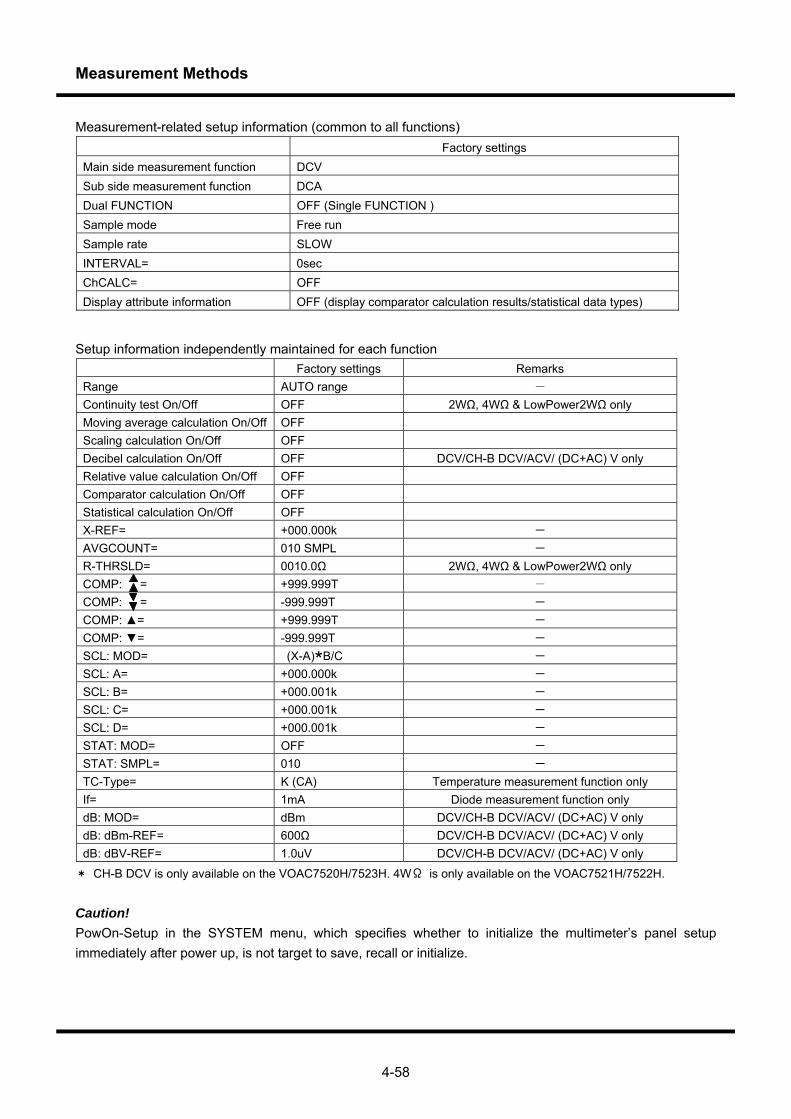
Measurement Methods
4-58
Measurement-related setup information (common to all functions) Factory settings Main side measurement function DCV Sub side measurement function DCA Dual FUNCTION OFF (Single FUNCTION ) Sample mode Free run Sample rate SLOW INTERVAL= 0sec ChCALC= OFF Display attribute information OFF (display comparator calculation results/statistical data types)
Setup information independently maintained for each function Factory settings Remarks Range AUTO range - Continuity test On/Off OFF 2WΩ, 4WΩ & LowPower2WΩ only Moving average calculation On/Off OFF Scaling calculation On/Off OFF Decibel calculation On/Off OFF DCV/CH-B DCV/ACV/ (DC+AC) V only Relative value calculation On/Off OFF Comparator calculation On/Off OFF Statistical calculation On/Off OFF X-REF= +000.000k - AVGCOUNT= 010 SMPL - R-THRSLD= 0010.0Ω 2WΩ, 4WΩ & LowPower2WΩ only COMP: = +999.999T - COMP: = -999.999T - COMP: = +999.999T - COMP: = -999.999T - SCL: MOD= (X-A)*B/C - SCL: A= +000.000k - SCL: B= +000.001k - SCL: C= +000.001k - SCL: D= +000.001k - STAT: MOD= OFF - STAT: SMPL= 010 - TC-Type= K (CA) Temperature measurement function only If= 1mA Diode measurement function only dB: MOD= dBm DCV/CH-B DCV/ACV/ (DC+AC) V only dB: dBm-REF= 600Ω DCV/CH-B DCV/ACV/ (DC+AC) V only dB: dBV-REF= 1.0uV DCV/CH-B DCV/ACV/ (DC+AC) V only
* CH-B DCV is only available on the VOAC7520H/7523H. 4WΩ is only available on the VOAC7521H/7522H.
Caution! PowOn-Setup in the SYSTEM menu, which specifies whether to initialize the multimeter’s panel setup immediately after power up, is not target to save, recall or initialize.
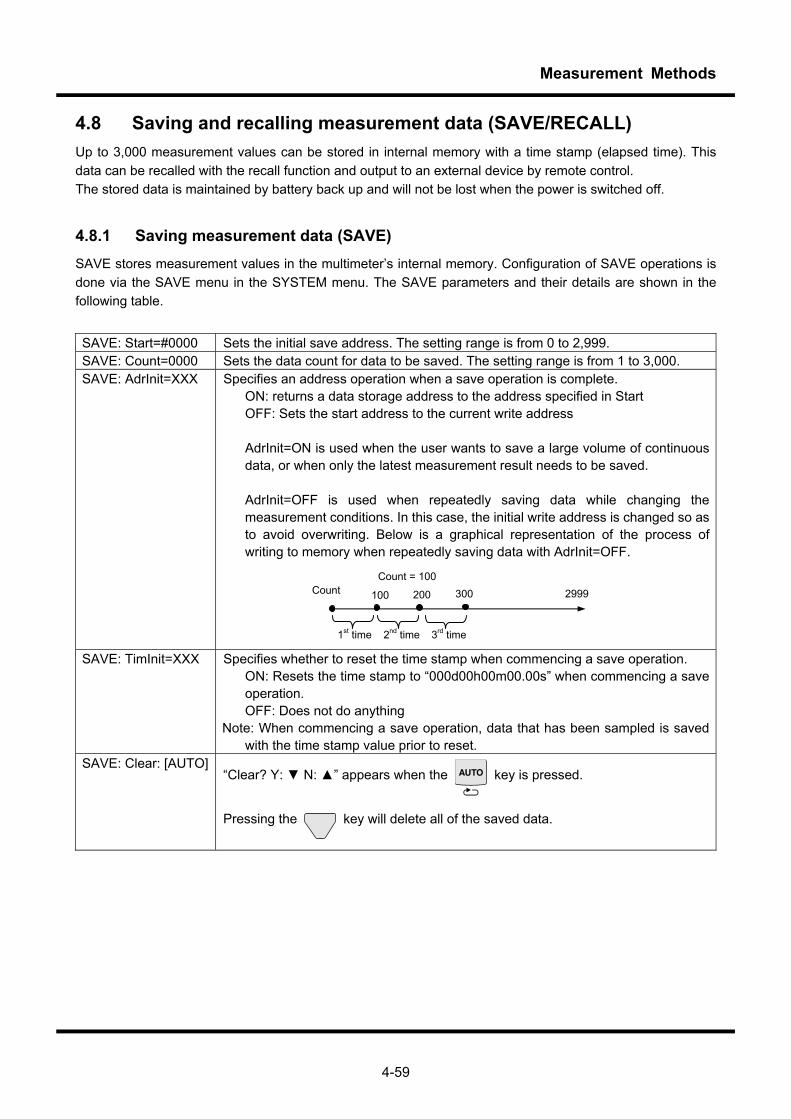
Measurement Methods
4-59
4.8 Saving and recalling measurement data (SAVE/RECALL) Up to 3,000 measurement values can be stored in internal memory with a time stamp (elapsed time). This data can be recalled with the recall function and output to an external device by remote control. The stored data is maintained by battery back up and will not be lost when the power is switched off.
4.8.1 Saving measurement data (SAVE) SAVE stores measurement values in the multimeter’s internal memory. Configuration of SAVE operations is done via the SAVE menu in the SYSTEM menu. The SAVE parameters and their details are shown in the following table.
SAVE: Start=#0000 Sets the initial save address. The setting range is from 0 to 2,999. SAVE: Count=0000 Sets the data count for data to be saved. The setting range is from 1 to 3,000. SAVE: AdrInit=XXX Specifies an address operation when a save operation is complete.
ON: returns a data storage address to the address specified in Start OFF: Sets the start address to the current write address AdrInit=ON is used when the user wants to save a large volume of continuous data, or when only the latest measurement result needs to be saved. AdrInit=OFF is used when repeatedly saving data while changing the measurement conditions. In this case, the initial write address is changed so as to avoid overwriting. Below is a graphical representation of the process of writing to memory when repeatedly saving data with AdrInit=OFF.
SAVE: TimInit=XXX Specifies whether to reset the time stamp when commencing a save operation. ON: Resets the time stamp to “000d00h00m00.00s” when commencing a save operation. OFF: Does not do anything
Note: When commencing a save operation, data that has been sampled is saved with the time stamp value prior to reset.
SAVE: Clear: [AUTO] “Clear? Y: N: ” appears when the key is pressed.
Pressing the key will delete all of the saved data.
Count = 100
1st time 2nd time 3rd time
Count 100 200 300 2999
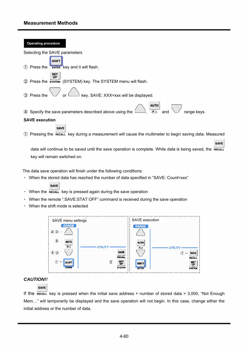
Measurement Methods
4-60
Selecting the SAVE parameters
① Press the key and it will flash.
② Press the (SYSTEM) key. The SYSTEM menu will flash.
③ Press the or key. SAVE: XXX=xxx will be displayed.
④ Specify the save parameters described above using the , and range keys.
SAVE execution
① Pressing the key during a measurement will cause the multimeter to begin saving data. Measured
data will continue to be saved until the save operation is complete. While data is being saved, the
key will remain switched on.
The data save operation will finish under the following conditions: ・ When the stored data has reached the number of data specified in “SAVE: Count=xxx”
・ When the key is pressed again during the save operation
・ When the remote “:SAVE:STAT OFF” command is received during the save operation ・ When the shift mode is selected
CAUTION!!
If the key is pressed when the initial save address + number of stored data > 3,000, “Not Enough
Mem…” will temporarily be displayed and the save operation will not begin. In this case, change either the
initial address or the number of data.
SAVE menu settings SAVE execution
Operating procedure

Measurement Methods
4-61
4.8.2 Save formats for measurement data
Data saved by the SAVE function is saved in different formats according to the statistical calculation settings or the difference between Single FUNCTION and Dual FUNCTION. 1,500 pairs of data or less can be saved at Dual FUNCTION. 1) Single FUNCTION + statistical calculation mode = OFF or CONT This format saves a single raw datum at each sampling. 2) Single FUNCTION operation + statistical calculation mode = REPEAT or SINGLE Every time the statistical calculation sample number, N, is reached, the four data for the statistical
calculation results (Max, Min, Avg and σ) are saved as a set. Raw data is not saved. All four of the statistical calculation results have the same time stamp.
The save sequence is Max, Min, Avg and σ. 3) Dual FUNCTION + statistical calculation mode = OFF or CONT This format saves the two data for Main side measurement results and Sub side measurement results as
a set. These two data both have the same time stamp. The save sequence is Main and Sub. 4) Dual FUNCTION + statistical calculation mode = REPEAT or SINGLE Every time the statistical calculation sample number, N, is reached, the four data for the statistical
calculation results on the Main side and the Sub side are saved as a combined set of eight data. Raw data is not saved. All eight of the statistical calculation results have the same time stamp.
The save sequence is Max, Min, Avg and σ on the Main side, and then Max, Min, Avg and σ on the Sub side.
4.8.3 Recalling measurement data (RECALL)
Switching between normal mode (measurement mode) and recall mode
① Press the key and it will flash.
② Press the (RECALL) key to enter the recall mode. The recall address will always be #0000.
③ Press the key to exit from the recall mode.
Recall mode screen In recall mode, specify the address (recall address) to display the measured value saved at that address. Specifying this address can simply be done by increasing/decreasing the current recall address by one, or by narrowing down the measurement conditions and jumping to the address. These two methods are used according to the following screens.
Operating procedure
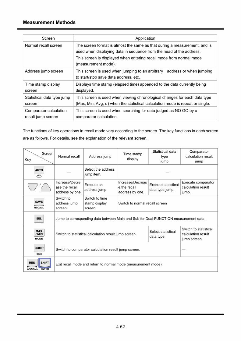
Measurement Methods
4-62
Screen Application
Normal recall screen The screen format is almost the same as that during a measurement, and is used when displaying data in sequence from the head of the address. This screen is displayed when entering recall mode from normal mode (measurement mode).
Address jump screen This screen is used when jumping to an arbitrary address or when jumping to start/stop save data address, etc.
Time stamp display screen
Displays time stamp (elapsed time) appended to the data currently being displayed.
Statistical data type jump screen
This screen is used when viewing chronological changes for each data type (Max, Min, Avg, σ) when the statistical calculation mode is repeat or single.
Comparator calculation result jump screen
This screen is used when searching for data judged as NO GO by a comparator calculation.
The functions of key operations in recall mode vary according to the screen. The key functions in each screen
are as follows. For details, see the explanation of the relevant screen.
Screen
Key Normal recall Address jump
Time stamp display
Statistical data type jump
Comparator calculation result
jump
―
Select the address jump item. ―
/ Increase/Decrease the recall address by one.
Execute an address jump.
Increase/Decrease the recall address by one.
Execute statistical data type jump.
Execute comparator calculation result jump.
Switch to address jump screen.
Switch to time stamp display screen.
Switch to normal recall screen
Jump to corresponding data between Main and Sub for Dual FUNCTION measurement data.
Switch to statistical calculation result jump screen.
Select statistical data type.
Switch to statistical calculation result jump screen.
Switch to comparator calculation result jump screen. ―
/ Exit recall mode and return to normal mode (measurement mode).
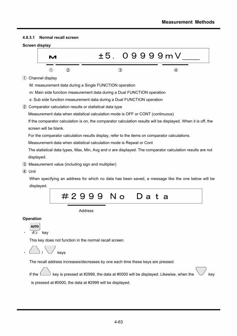
Measurement Methods
4-63
4.8.3.1 Normal recall screen
Screen display
M ±5.09999mV__ ① ② ③ ④
① Channel display
M: measurement data during a Single FUNCTION operation
m: Main side function measurement data during a Dual FUNCTION operation
s: Sub side function measurement data during a Dual FUNCTION operation
② Comparator calculation results or statistical data type
Measurement data when statistical calculation mode is OFF or CONT (continuous)
If the comparator calculation is on, the comparator calculation results will be displayed. When it is off, the
screen will be blank.
For the comparator calculation results display, refer to the items on comparator calculations.
Measurement data when statistical calculation mode is Repeat or Cont
The statistical data types, Max, Min, Avg and σ are displayed. The comparator calculation results are not
displayed.
③ Measurement value (including sign and multiplier)
④ Unit
When specifying an address for which no data has been saved, a message like the one below will be
displayed.
#2999 No Data Address
Operation
・ key
This key does not function in the normal recall screen.
・ / keys
The recall address increases/decreases by one each time these keys are pressed.
If the key is pressed at #2999, the data at #0000 will be displayed. Likewise, when the key
is pressed at #0000, the data at #2999 will be displayed.
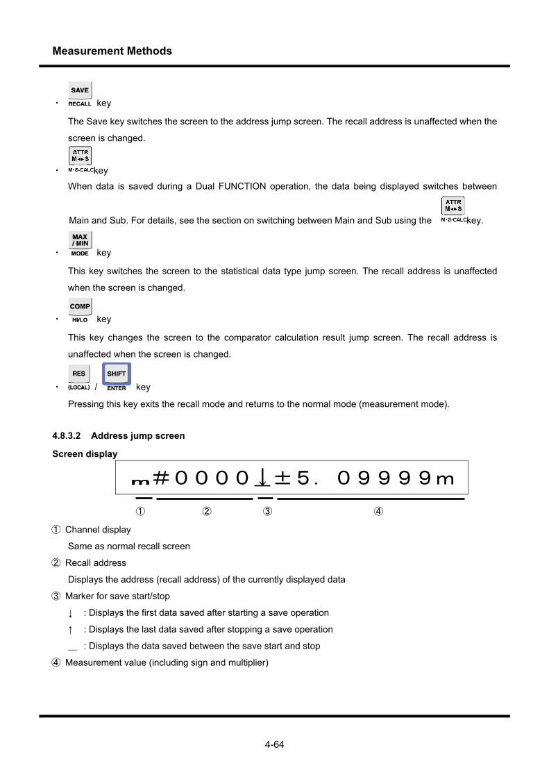
Measurement Methods
4-64
・ key
The Save key switches the screen to the address jump screen. The recall address is unaffected when the
screen is changed.
・ key
When data is saved during a Dual FUNCTION operation, the data being displayed switches between
Main and Sub. For details, see the section on switching between Main and Sub using the key.
・ key
This key switches the screen to the statistical data type jump screen. The recall address is unaffected
when the screen is changed.
・ key
This key changes the screen to the comparator calculation result jump screen. The recall address is
unaffected when the screen is changed.
・ / key
Pressing this key exits the recall mode and returns to the normal mode (measurement mode).
4.8.3.2 Address jump screen
Screen display
m#0000↓±5.09999m
① ② ③ ④
① Channel display
Same as normal recall screen
② Recall address
Displays the address (recall address) of the currently displayed data
③ Marker for save start/stop
↓ : Displays the first data saved after starting a save operation
↑ : Displays the last data saved after stopping a save operation
_ : Displays the data saved between the save start and stop
④ Measurement value (including sign and multiplier)
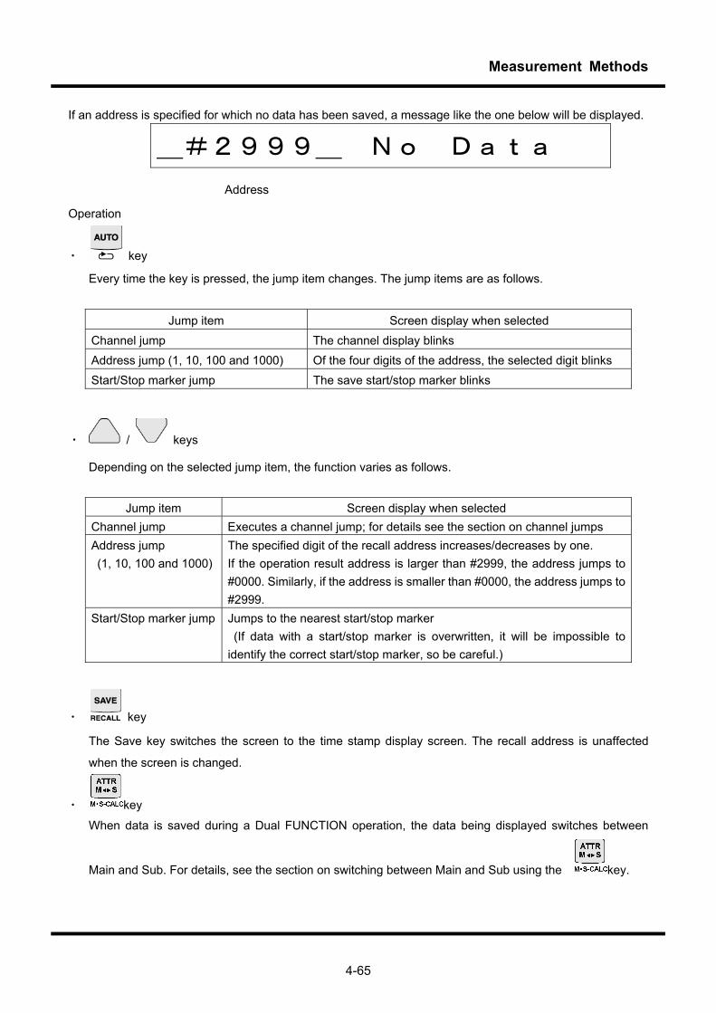
Measurement Methods
4-65
If an address is specified for which no data has been saved, a message like the one below will be displayed.
_#2999_ No Data Address
Operation
・ key
Every time the key is pressed, the jump item changes. The jump items are as follows.
Jump item Screen display when selected Channel jump The channel display blinks Address jump (1, 10, 100 and 1000) Of the four digits of the address, the selected digit blinks Start/Stop marker jump The save start/stop marker blinks
・ / keys
Depending on the selected jump item, the function varies as follows.
Jump item Screen display when selected
Channel jump Executes a channel jump; for details see the section on channel jumps Address jump (1, 10, 100 and 1000)
The specified digit of the recall address increases/decreases by one. If the operation result address is larger than #2999, the address jumps to #0000. Similarly, if the address is smaller than #0000, the address jumps to #2999.
Start/Stop marker jump Jumps to the nearest start/stop marker (If data with a start/stop marker is overwritten, it will be impossible to identify the correct start/stop marker, so be careful.)
・ key
The Save key switches the screen to the time stamp display screen. The recall address is unaffected
when the screen is changed.
・ key
When data is saved during a Dual FUNCTION operation, the data being displayed switches between
Main and Sub. For details, see the section on switching between Main and Sub using the key.
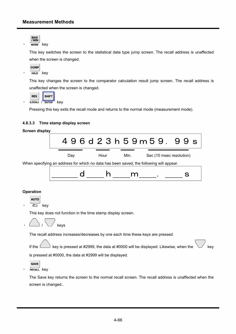
Measurement Methods
4-66
・ key
This key switches the screen to the statistical data type jump screen. The recall address is unaffected
when the screen is changed.
・ key
This key changes the screen to the comparator calculation result jump screen. The recall address is
unaffected when the screen is changed.
・ / key
Pressing this key exits the recall mode and returns to the normal mode (measurement mode).
4.8.3.3 Time stamp display screen
Screen display
496d23h59m59.99s
Day Hour Min. Sec (10 msec resolution)
When specifying an address for which no data has been saved, the following will appear.
___d__h__m__.__s
Operation
・ key
This key does not function in the time stamp display screen.
・ / keys
The recall address increases/decreases by one each time these keys are pressed.
If the key is pressed at #2999, the data at #0000 will be displayed. Likewise, when the key
is pressed at #0000, the data at #2999 will be displayed.
・ key
The Save key returns the screen to the normal recall screen. The recall address is unaffected when the
screen is changed..
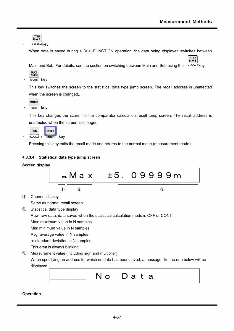
Measurement Methods
4-67
・ key
When data is saved during a Dual FUNCTION operation, the data being displayed switches between
Main and Sub. For details, see the section on switching between Main and Sub using the key.
・ key
This key switches the screen to the statistical data type jump screen. The recall address is unaffected
when the screen is changed..
・ key
This key changes the screen to the comparator calculation result jump screen. The recall address is
unaffected when the screen is changed.
・ / key
Pressing this key exits the recall mode and returns to the normal mode (measurement mode).
4.8.3.4 Statistical data type jump screen
Screen display
sMax ±5.09999m ① ② ③
① Channel display Same as normal recall screen ② Statistical data type display Raw: raw data; data saved when the statistical calculation mode is OFF or CONT Max: maximum value in N samples Min: minimum value in N samples Avg: average value in N samples σ: standard deviation in N samples This area is always blinking. ③ Measurement value (including sign and multiplier) When specifying an address for which no data has been saved, a message like the one below will be
displayed.
____ No Data
Operation
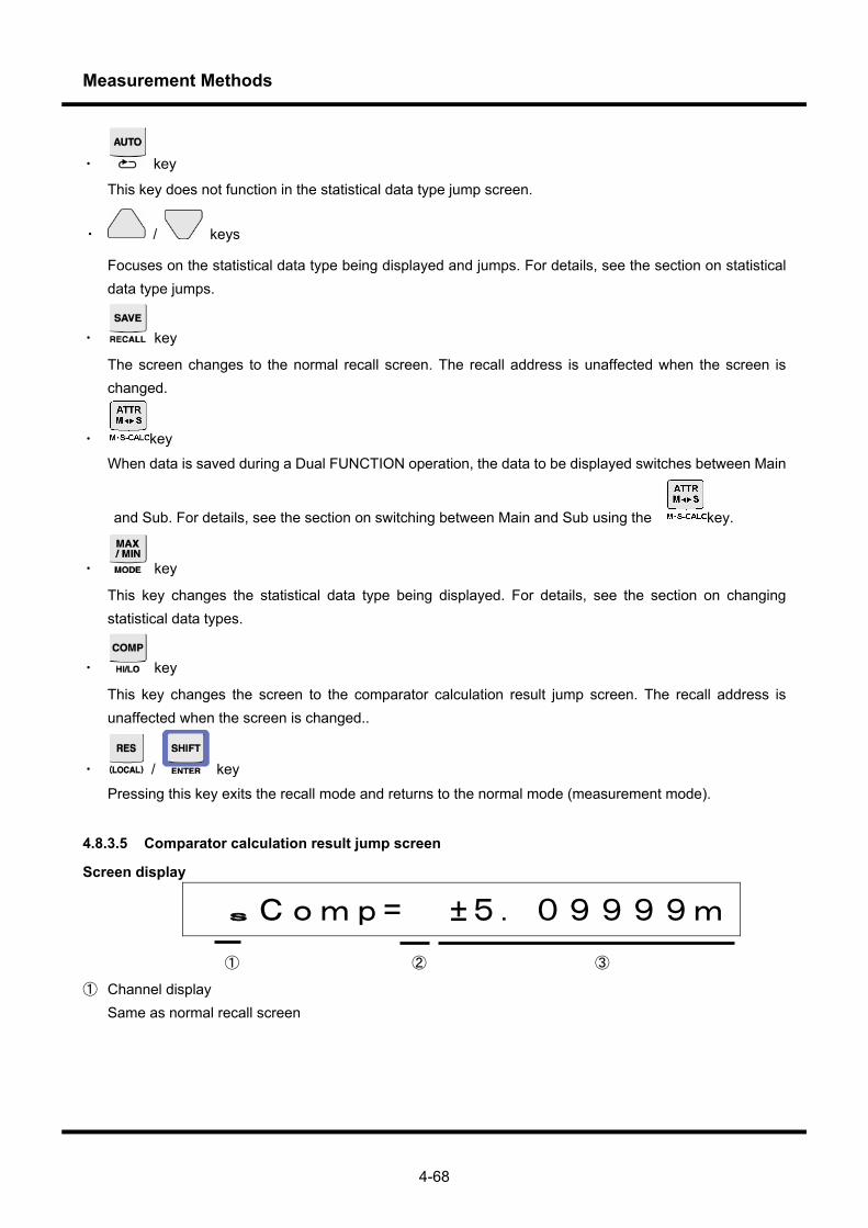
Measurement Methods
4-68
・ key
This key does not function in the statistical data type jump screen.
・ / keys
Focuses on the statistical data type being displayed and jumps. For details, see the section on statistical data type jumps.
・ key
The screen changes to the normal recall screen. The recall address is unaffected when the screen is changed.
・ key
When data is saved during a Dual FUNCTION operation, the data to be displayed switches between Main
and Sub. For details, see the section on switching between Main and Sub using the key.
・ key
This key changes the statistical data type being displayed. For details, see the section on changing statistical data types.
・ key
This key changes the screen to the comparator calculation result jump screen. The recall address is unaffected when the screen is changed..
・ / key
Pressing this key exits the recall mode and returns to the normal mode (measurement mode).
4.8.3.5 Comparator calculation result jump screen
Screen display
sComp= ±5.09999m ① ② ③
① Channel display Same as normal recall screen

Measurement Methods
4-69
② Comparator calculation result display _ : data when comparator calculation is off : RED level High : YELLOW level High : GO : YELLOW level Low : RED level Low This area is always blinking. ③ Measurement value (including sign and multiplier) When specifying an address for which no data has been saved, a message like the one below will be
displayed.
_Comp=_ No Data
Operation
・ key
This key does not function in the comparator calculation result jump screen.
・ / keys
These keys are used to jump to the address for comparator calculation results that have changed. For details, see the section on comparator calculation results jump.
・ key
Changes the screen to the normal recall screen. The recall address is unaffected when the screen is changed.
・ key
When data is saved during a Dual FUNCTION operation, the data to be displayed switches between Main
and Sub. For details, see the section on switching between Main and Sub using the key.
• key
Changes the screen to the statistical data type jump screen. The recall address is unaffected when the screen is changed.
・ key
This key does not function in the comparator calculation result jump screen.
・ / key

Measurement Methods
4-70
Pressing this key exits the recall mode and returns to the normal mode (measurement mode).
4.8.3.6 Switching between Main and Sub with the selection key
When data is saved during a Dual FUNCTION operation, the respective function measurement values on the
Main side and Sub side are alternatively saved as a set. Every time the key is pressed, the screen
changes to the corresponding Main side and Sub side data.
Switching between Main and Sub when the statistical calculation mode is OFF or CONT
Address Screen image (for normal recall screen)
#0000 m 5.09999mA#0001 s -3.0999 V
#0002 m 4.09999mA
#0003 s 3.0999 V
・ ・
・ ・
Changes with each key press
Changes with each key press
Switching between Main and Sub when the statistical calculation mode is REPEAT or SINGLE
Address Screen image (for statistical data type jump screen)
#0000 mMax___+5.09999m
#0001 mMin___+3.09999m
#0002 mAvg___+4.09999m
#0003 m σ ___+0.00005m
#0004 sMax___ +3.0999
#0005 sMin___ -3.0999
#0006 sAvg___ +0.0000
#0007 s σ ___ +0.1000
・ ・ ・
・ ・ ・
Changes with each key press
4.8.3.7 Channel jump
Channel jump is a function that recalls data saved during a Dual FUNCTION operation centered on either the
Main side function or the Sub side function. For example, if the function is executed when displaying Main
side function data (“m”or “M”), it skips the Sub side function measurement data, and jumps to the next Main
side function data. Likewise, when displaying Sub side function data (“s”), it skips to the next Sub side
function data.
To change the channel that is being focused on, switch between Main and Sub using the key.
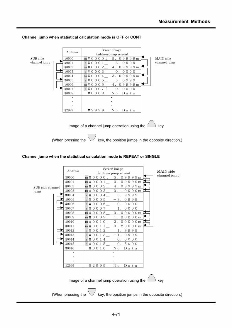
Measurement Methods
4-71
Channel jump when statistical calculation mode is OFF or CONT
Address Screen image (address jump screen)
#0000 m#0000↓ 5.09999m
#0001 s#0001_ 3.0999
#0002 m#0002_ 4.09999m
#0003 s#0003_ 0.0000
#0004 m#0004_ 3.09999m
#0005 s#0005_ -3.0999
#0006 m#0006_ 4.09999m
#0007 s#0007↑ 0.0000
#0008 _#0008_ No Data
・ ・ ・
・ ・ ・
#2999 _#2999_ No Data
MAIN side channel jump
SUB side channel jump
Image of a channel jump operation using the key
(When pressing the key, the position jumps in the opposite direction.)
Channel jump when the statistical calculation mode is REPEAT or SINGLE
Address Screen image (address jump screen)
#0000 m#0000↓ 5.09999m
#0001 m#0001_ 3.09999m
#0002 m#0002_ 4.09999m
#0003 m#0003_ 0.10000m
#0004 s#0004_ 3.9999
#0005 s#0005_ -3.0999
#0006 s#0006_ 0.0000
#0007 s#0007_ 1.0000
#0008 m#0008_ 3.00000m
#0009 m#0009_ 1.00000m
#0010 m#0010_ 2.00000m
#0011 m#0011_ 0.20000m
#0012 s#0012_ 1.9999
#0013 s#0013_ -1.0999
#0014 s#0014_ 0.0000
#0015 s#0015_ 0.5000
#0016 _#0016_ No Data
・ ・ ・
・ ・ ・
#2999 _#2999_ No Data
SUB side channel jump
MAIN side channel jump
Image of a channel jump operation using the key
(When pressing the key, the position jumps in the opposite direction.)
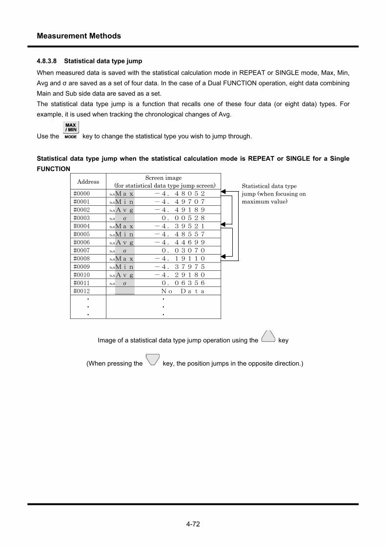
Measurement Methods
4-72
4.8.3.8 Statistical data type jump
When measured data is saved with the statistical calculation mode in REPEAT or SINGLE mode, Max, Min, Avg and σ are saved as a set of four data. In the case of a Dual FUNCTION operation, eight data combining Main and Sub side data are saved as a set. The statistical data type jump is a function that recalls one of these four data (or eight data) types. For example, it is used when tracking the chronological changes of Avg.
Use the key to change the statistical type you wish to jump through.
Statistical data type jump when the statistical calculation mode is REPEAT or SINGLE for a Single FUNCTION
Address Screen image (for statistical data type jump screen)
#0000 MMax -4.48052
#0001 MMin -4.49707
#0002 MAvg -4.49189
#0003 M σ 0.00528
#0004 MMax -4.39521
#0005 MMin -4.48557
#0006 MAvg -4.44699
#0007 M σ 0.03070
#0008 MMax -4.19110
#0009 MMin -4.37975
#0010 MAvg -4.29180
#0011 M σ 0.06356
#0012 ____ No Data
・ ・ ・
・ ・ ・
Statistical data type jump (when focusing on maximum value)
Image of a statistical data type jump operation using the key
(When pressing the key, the position jumps in the opposite direction.)
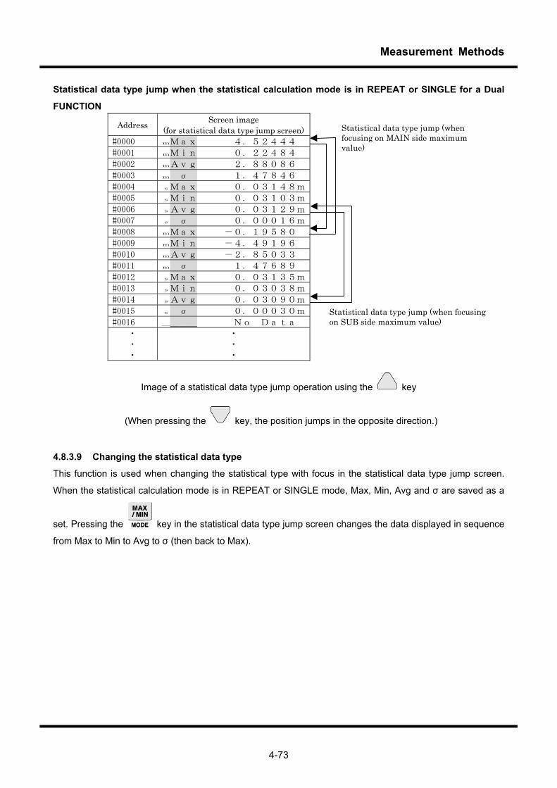
Measurement Methods
4-73
Statistical data type jump when the statistical calculation mode is in REPEAT or SINGLE for a Dual
FUNCTION
Address Screen image (for statistical data type jump screen)
#0000 mMax 4.52444
#0001 mMin 0.22484
#0002 mAvg 2.88086
#0003 m σ 1.47846
#0004 sMax 0.03148m
#0005 sMin 0.03103m
#0006 sAvg 0.03129m
#0007 s σ 0.00016m
#0008 mMax -0.19580
#0009 mMin -4.49196
#0010 mAvg -2.85033
#0011 m σ 1.47689
#0012 sMax 0.03135m
#0013 sMin 0.03038m
#0014 sAvg 0.03090m
#0015 s σ 0.00030m
#0016 ____ No Data
・ ・ ・
・ ・ ・
Statistical data type jump (when focusing on MAIN side maximum value)
Statistical data type jump (when focusing on SUB side maximum value)
Image of a statistical data type jump operation using the key
(When pressing the key, the position jumps in the opposite direction.)
4.8.3.9 Changing the statistical data type
This function is used when changing the statistical type with focus in the statistical data type jump screen.
When the statistical calculation mode is in REPEAT or SINGLE mode, Max, Min, Avg and σ are saved as a
set. Pressing the key in the statistical data type jump screen changes the data displayed in sequence
from Max to Min to Avg to σ (then back to Max).
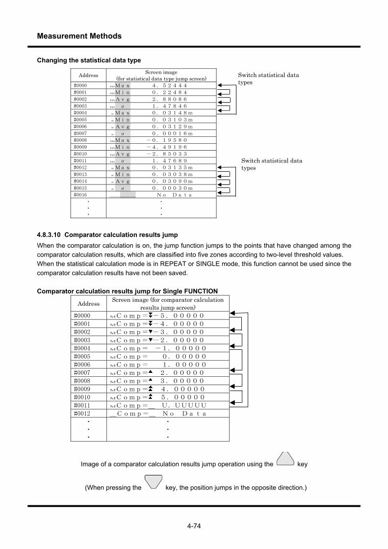
Measurement Methods
4-74
Changing the statistical data type
Address Screen image (for statistical data type jump screen)
#0000 mMax 4.52444
#0001 mMin 0.22484
#0002 mAvg 2.88086
#0003 m σ 1.47846
#0004 sMax 0.03148m
#0005 sMin 0.03103m
#0006 sAvg 0.03129m
#0007 s σ 0.00016m
#0008 mMax -0.19580
#0009 mMin -4.49196
#0010 mAvg -2.85033
#0011 m σ 1.47689
#0012 sMax 0.03135m
#0013 sMin 0.03038m
#0014 sAvg 0.03090m
#0015 s σ 0.00030m
#0016 ____ No Data
・
・ ・
・
・ ・
Switch statistical data types
Switch statistical data types
4.8.3.10 Comparator calculation results jump When the comparator calculation is on, the jump function jumps to the points that have changed among the comparator calculation results, which are classified into five zones according to two-level threshold values. When the statistical calculation mode is in REPEAT or SINGLE mode, this function cannot be used since the comparator calculation results have not been saved. Comparator calculation results jump for Single FUNCTION
Address Screen image (for comparator calculation results jump screen)
#0000 MComp= -5.00000
#0001 MComp= -4.00000
#0002 MComp= -3.00000
#0003 MComp= ―2.00000
#0004 MComp= -1.00000
#0005 MComp= 0.00000
#0006 MComp= 1.00000
#0007 MComp= 2.00000
#0008 MComp= 3.00000
#0009 MComp= 4.00000
#0010 MComp= 5.00000
#0011 MComp=_ U.UUUUU
#0012 _Comp=_ No Data
・ ・ ・
・ ・ ・
Image of a comparator calculation results jump operation using the key
(When pressing the key, the position jumps in the opposite direction.)
Measurement Methods
4-75
During a Dual FUNCTION operation, the currently displayed results and those on the same side can be searched, while the results on the other side are disregarded.
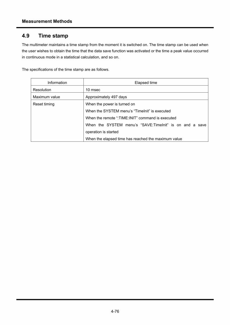
Measurement Methods
4-76
4.9 Time stamp The multimeter maintains a time stamp from the moment it is switched on. The time stamp can be used when the user wishes to obtain the time that the data save function was activated or the time a peak value occurred in continuous mode in a statistical calculation, and so on. The specifications of the time stamp are as follows.
Information Elapsed time
Resolution 10 msec
Maximum value Approximately 497 days
Reset timing When the power is turned on
When the SYSTEM menu’s “TimeInit” is executed
When the remote “:TIME:INIT” command is executed
When the SYSTEM menu’s “SAVE:TimeInit” is on and a save
operation is started
When the elapsed time has reached the maximum value
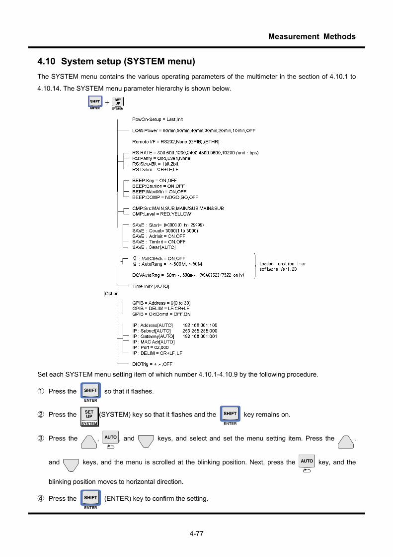
Measurement Methods
4-77
4.10 System setup (SYSTEM menu) The SYSTEM menu contains the various operating parameters of the multimeter in the section of 4.10.1 to
4.10.14. The SYSTEM menu parameter hierarchy is shown below.
Set each SYSTEM menu setting item of which number 4.10.1-4.10.9 by the following procedure.
① Press the so that it flashes.
② Press the (SYSTEM) key so that it flashes and the key remains on.
③ Press the , , and keys, and select and set the menu setting item. Press the ,
and keys, and the menu is scrolled at the blinking position. Next, press the key, and the
blinking position moves to horizontal direction.
④ Press the (ENTER) key to confirm the setting.
Measurement Methods
4-78
4.10.1 Setup at power on
In the PowOn-Setup menu, it is possible to specify whether or not to reset this product’s panel setup immediately after the power is switched on. Last: maintains the panel setup configured when the power was previously switched off Init: resets the setup to the factory settings each time the power is activated (Refer to section 4.7)
4.10.2 Setting up energy saving mode The time until the multimeter switches to the energy saving mode is specified in the LOW-POWER menu. In this mode, when there has been no input from the keys within the specified time, the display switches off and the multimeter enters the energy saving mode. When this mode is off, the multimeter will not switch to the energy saving mode. Pressing any key cancels the energy saving mode. Even when in remote state, the display returns when a key is operated. However, processing corresponding to the key operation will not be performed.
4.10.3 Setting up remote control interface
The multimeter can be controlled remotely by RS-232, GP-IB or Ethernet. (GP-IB and Ethernet are options). In the remote interface menu, the user specifies whether which interface to use to control the multimeter. RS232 : select RS-232 GPIB : select GP-IB ETHER : select Ethernet NONE : remote control is not performed The GPIB and ETHER choices are only displayed when the optional boards are installed.
CAUTIONS!!
Select the above-mentioned remote interface by operating the system menu of section 4.10 in the
instruction manual before controlling this instrument remotely.
For remote state When a remote command is received, the multimeter enters the remote state. To cancel the remote state,
press the (LOCAL) key. In remote state, input from keys other than the key is disregarded.
4.10.4 Setting up RS-232 communication
The communication parameters are set via the RS menu when controlling the multimeter remotely by RS-232.
For details of the communication system, refer to the Remote Manual.
RATE=XXX This command sets the communication rate to 300, 600, 1200, 2400, 4800, 9600 or
19,200 bps.
Parity=XXX This command sets the parity bit to None, Odd or Even.
Stop-Bit=XXX This command sets the length of the stop bit to 1 bit or 2 bits.
Data-Lng=XXX This command sets the data length to 7 bits or 8 bits.
Delim=XXX This command sets the delimiter of response messages for communicating with an
external device to CR+LF or LF.
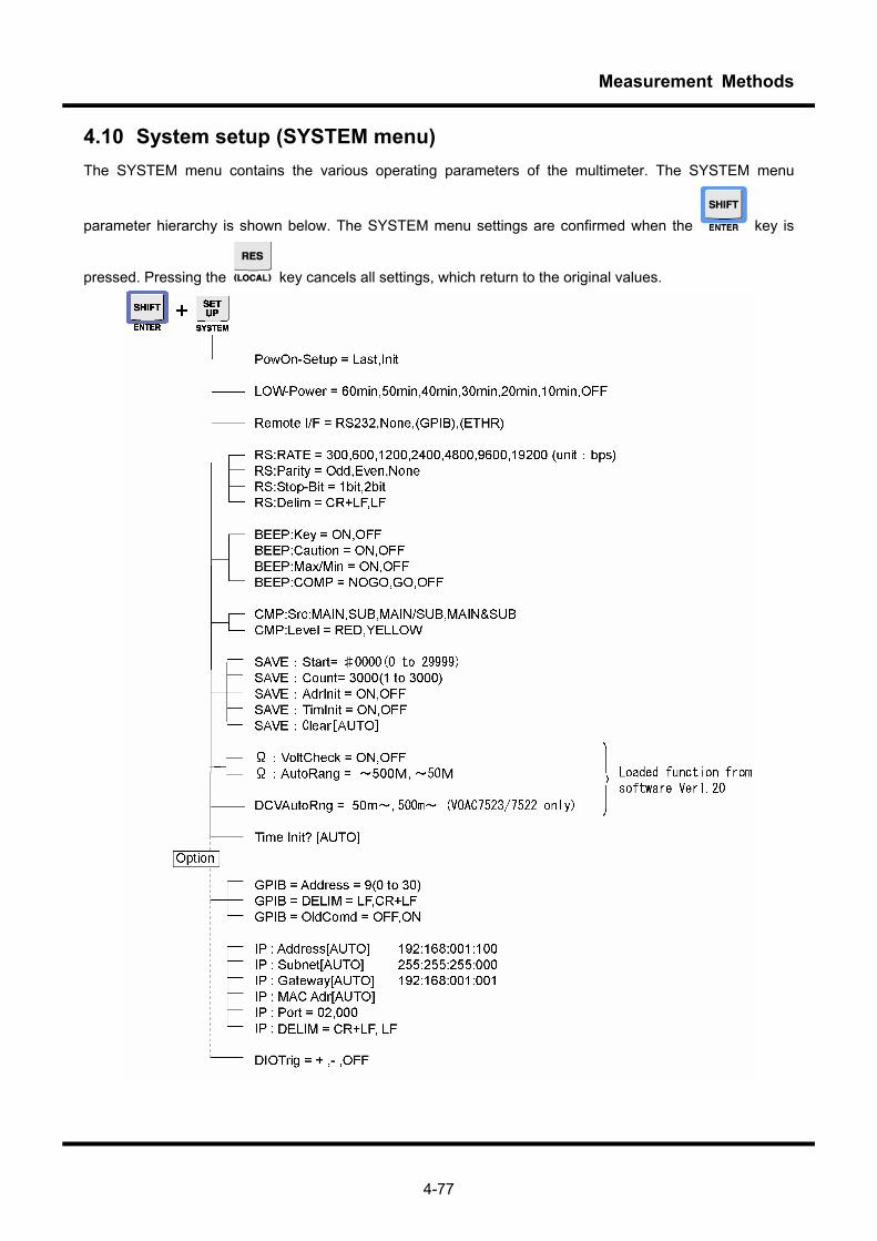
Measurement Methods
4-77
4.10 System setup (SYSTEM menu) The SYSTEM menu contains the various operating parameters of the multimeter. The SYSTEM menu
parameter hierarchy is shown below. The SYSTEM menu settings are confirmed when the key is
pressed. Pressing the key cancels all settings, which return to the original values.
Measurement Methods
4-78
4.10.1 Setup at power on
In the PowOn-Setup menu, it is possible to specify whether or not to reset this product’s panel setup immediately after the power is switched on. Last: maintains the panel setup configured when the power was previously switched off Init: resets the setup to the factory settings each time the power is activated (Refer to section 4.7)
4.10.2 Setting up energy saving mode
The time until the multimeter switches to the energy saving mode is specified in the LOW-POWER menu. In this mode, when there has been no input from the keys within the specified time, the display switches off and the multimeter enters the energy saving mode. When this mode is off, the multimeter will not switch to the energy saving mode. Pressing any key cancels the energy saving mode. Even when in remote state, the display returns when a key is operated. However, processing corresponding to the key operation will not be performed.
4.10.3 Setting up remote control interface
The multimeter can be controlled remotely by RS-232, GP-IB or Ethernet. (GP-IB and Ethernet are options). In the remote interface menu, the user specifies whether which interface to use to control the multimeter. RS232 : select RS-232 GPIB : select GP-IB ETHER : select Ethernet NONE : remote control is not performed The GPIB and ETHER choices are only displayed when the optional boards are installed.
CAUTIONS!! Remote state When a remote command is received, the multimeter enters the remote state. To cancel the remote state,
press the (LOCAL) key. In remote state, input from keys other than the key is disregarded.
4.10.4 Setting up RS-232 communication
The communication parameters are set via the RS menu when controlling the multimeter remotely by RS-232.
For details of the communication system, refer to the Remote Manual.
RATE=XXX This command sets the communication rate to 300, 600, 1200, 2400, 4800, 9600 or
19,200 bps.
Parity=XXX This command sets the parity bit to None, Odd or Even.
Stop-Bit=XXX This command sets the length of the stop bit to 1 bit or 2 bits.
Data-Lng=XXX This command sets the data length to 7 bits or 8 bits.
Delim=XXX This command sets the delimiter of response messages for communicating with an
external device to CR+LF or LF.
Measurement Methods
4-79
4.10.5 Setting up GPIB communication
The communication parameters are set via the GPIB menu when controlling the multimeter remotely by GPIB. This menu only appears when the GPIB unit (optional) is installed. For details of the communication system, refer to the Remote Manual. Address=XX This command sets the GPIB address from 0 to 30. Delim=XXX This command sets the delimiter of response messages for communicating with an
external device to CR+LF or LF. OldComd=XXX This command specifies whether to use the standard command system or a
compatible command system from previous models. The choices are OFF or ON. OFF : use the standard command system ON : use a compatible command system from a previous model
4.10.6 Setting up Ethernet communication
The communication parameters are set via the IP menu when controlling the multimeter remotely via a TCP/IP connection via Ethernet. This menu only appears when the Ethernet unit (optional) is installed. For details of the communication system, refer to the Remote Manual. Address [AUTO] This command specifies the IP address used to communicate with the multimeter. The
IP address setup screen appears when the key is pressed. If the key is
pressed when the cursor is at the end of the IP address, the cursor returns to the
beginning of the IP menu.
Subnet [AUTO] This command specifies the subnet mask of the network connected to the multimeter. Operation is the same as for setting up the IP address.
Gateway [AUTO] This command specifies the default gateway address. Operation is the same as for setting up the IP address.
MACAdr [AUTO] This command confirms the MAC address of the optional Ethernet board. The address cannot be altered.
Port=XXXXX This command specifies the number of the board used in communicating with the multimeter.
Delim=XXX This command sets the delimiter of response messages for communicating with an external device to CR+LF or LF.
4.10.7 Setting up beep activation conditions
The activation of a beep sound for certain events, such as when a key is pressed or when a measurement
error occurs, can be done via the BEEP menu.
Key=XXX This command specifies whether to activate a beep sound when a key is pressed. The
function parameter can be set to ON or OFF. Caution=XXX This command specifies whether a beep sound is activated when any of the following
errors occur. The function parameter can be set to ON or OFF. ・ Scaling calculation overflow
Measurement Methods
4-80
・ Log (0) error in decibel calculation ・ Contradiction in comparator calculation setting (i.e., upper limit < lower limit )
Max/Min=XXX This command specifies whether to activate a beep sound when max or min is updated when conducting a statistical calculation in CONT (continuous) mode. The function parameter can be set to ON or OFF.
COMP=XXX This command specifies whether to activate a beep sound according to calculation results when the comparator calculation is on. The function parameter can be set to NOGO, GO or OFF. For details, see the section on comparator calculations.
4.10.8 Setting up output conditions for comparator calculations
This function is used to set up the conditions for outputting comparator calculation results to a beep sound or to an optional DIO device. For details, see the sections on comparator calculations and the optional DIO device. CMP: SRC=XXX This command specifies whether to output the calculation result from Main or Sub
during a Dual FUNCTION operation. The parameter can be set to MAIN, SUB, MAIN/SUB or MAIN & SUB.
CMP: Level=XXX This command specifies which level to use as the basis for the output among the two-level comparative values. The parameter can be set to RED or YELLOW.
4.10.9 Setting up the data SAVE function
This function specifies the memory and operating settings of the data SAVE function. For details, refer to the section on saving data. SAVE: Start=#XXXX This command specifies the initial address at which data is saved. The parameter
ranges from 0 to 2999. SAVE: Count=XXXX This command specifies the number of data saved during a single measurement. The
parameter ranges from 1 to 3000. SAVE: AdrInit=XXX This command specifies whether to return the initial address to the beginning (Init) or
to move the address to the last saved address+1 when a data save operation is completed. The parameter can be set to ON or OFF. When ON, the initial address reverts to the beginning.
SAVE: TimInit=XXX This command specifies whether to reset (Init) the time stamp when a data save operation begins. The parameter can be set to ON or OFF. When ON, the time stamp is reset to “000day00h00m00.00s” when a save operation begins.
SAVE: Clear [AUTO] This command resets all saved data.
Measurement Methods
4-81
4.10.10 Function for protecting resistance measuring circuit and AUTO range settings
4.10.10.1 External voltage checking function, Ω:VoltCheck
This function is used to check the voltage applied in 2WΩ/4WΩ/Lo-Ω resistance measurements and diode measurements. When measuring resistance or the forward voltage of a diode, the correct measurements cannot be made if the voltage is applied externally. Furthermore, this product may be damaged if a voltage exceeding the specification is applied. Therefore, when switching from another function to resistance or diode measurement functions, the product automatically checks for the presence of voltages exceeding about 100V. When a voltage exceeding about 100V is detected, the product forcefully returns to the original function. If it is clear that there is no external voltage, the auto-checking function can be cancelled so that the measurement is promptly made. The following settings can be selected via the system menu: Ω:VoltCheck= ON: A voltage check is carried out when switching from another function to
resistance/diode testing (default settings) OFF: A voltage check is not carried out
The default setting is Ω:VoltCheck = ON. The procedure for changing the automatic check function is as
follows:
① Press the so that it flashes.
② Press the (SYSTEM) key so that it flashes and the key remains on.
③ Select Ω:VoltCheck using the , , and keys, and select ON or OFF.
④ Press the (ENTER) key to confirm the setting.
4.10.10.2 AUTO range settings, Ω:AutoRang
This function is used to adjust AUTO range settings for 2WΩ/4WΩ resistance measurements.
In contrast to the response time of about one second for SLOW samples of 50Ω-50MΩ for 2WΩ/4WΩ, the 5
seconds response in the 500MΩ range is slow. When the 500MΩ range is unnecessary and a high-speed
AUTO range response is necessary, the 500MΩ range can be omitted from the AUTO range.
Operating procedure

Measurement Methods
4-82
The following settings can be selected via the system menu:
Ω:AutoRang= Up to 500M: All ranges are in AUTO range (default setting) Up to 50M: 50MΩ and below are in AUTO range, excluding the 500MΩ range
The default setting is Ω:AutoRang = Up to 500M. The procedure for changing the AUTO range is as follows:
① Press the so that it flashes.
② Press the (SYSTEM) so that it flashes and the key remains on.
③ Select Ω:AutoRang using the , , and keys, and select Up to 500M or Up to 50M.
④ Press the key to confirm the setting.
4.10.11 Setting AUTO range in voltage measurements
This function is used to set the DCV AUTO range in VOAC7522H/7523H. In contrast to the response time of about 0.25 seconds/sample for SLOW samples in the 500mV-1000V DC range, the 2 seconds/sample response in the 50mV DC range for the VOAC7522H/7523H is slow. When the 50mV range is unnecessary and a high-speed AUTO range response is necessary, the DC50mV range can be omitted from the AUTO range. The following settings can be selected via the system menu: DCV AutoRng=
Up to 50m: All ranges are in AUTO range (default setting) Up to 500m: 500mV and below are in AUTO range, excluding the 50mV range
The default setting is DCV AutoRng = From 50m. The procedure for changing the AUTO range is as follows:
① Press the key so that it flashes.
② Press the (SYSTEM) key so that it flashes and the key remains on.
③ Select DCV:AutoRng using , , and keys, and select up to 50 m- or up to 500 m-.
④ Press the key to confirm the setting.
Operating procedure
Operating procedure
Measurement Methods
4-83
4.10.12 Setting the frequency of AC filter
When the sample rate is SLOW in ACV, (DC+AC) V, ACA, and (DC+AC) A measurement, the time (settling
time) to wait for the stability of the internal circuit can be sped up by setting the AC filter according to the
frequency of the measurement signal. The setting of the AC filter influences the lower bound frequency that
can be measured, and the setting time. The settling time is shortened when the AC filter frequency is set to
"200Hz-", and the response for the change of the range and the measurement function quickens. Still, this
setting is effective when the sample rate is only SLOW. This setting doesn't influence the operation at
MID/FAST.
The following settings can be selected in the system menu.
AC(Slow)=
15 Hz- : 15 Hz or more can be measured with Settling time 3 sec. (Factory settings)
200 Hz- : 200 Hz or more can be measured with Settling time 1 sec.
AC(Slow) = 15Hz- is set at the factory settings. The operating procedure of the setting the AC filter frequency
is shown.
① Press the key so that it flashes.
② Press the (SYSTEM) key so that it flashes and the key remains on.
③ Select AC (Slow) using , , and keys, and select up to 15 Hz -or up to 200 Hz-.
④ Press the key to confirm the setting.
4.10.13 Initializing the time stamp
Pressing the key when “TimeInit? [AUTO]” is displayed in the SYSTEM menu resets the time stamp to
“000day00h00m00.00s.”
4.10.14 Setting up external triggers
This menu I used to set up an external trigger operation for the DIO unit (optional). This menu only appears when the DIO unit (optional) is installed. For details, see the section on the DIO option. DIOTrig=XXX This command specifies an external trigger operation (trailing edge/leading
edge/trigger off). The parameter can be -, + or OFF.
Operating procedure
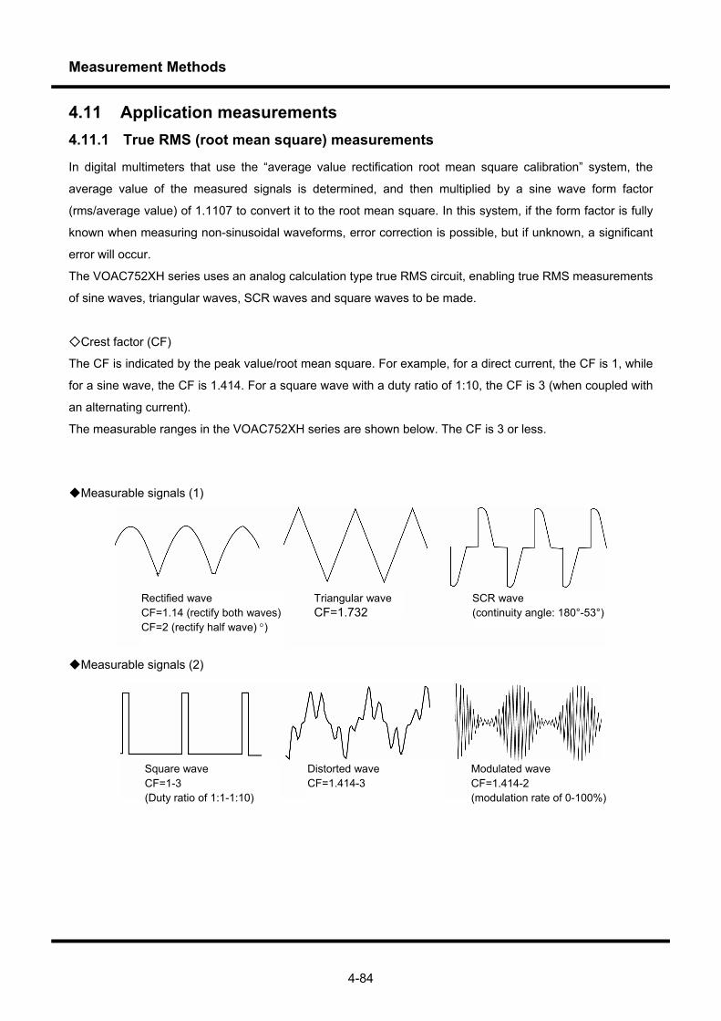
Measurement Methods
4-84
4.11 Application measurements 4.11.1 True RMS (root mean square) measurements
In digital multimeters that use the “average value rectification root mean square calibration” system, the
average value of the measured signals is determined, and then multiplied by a sine wave form factor
(rms/average value) of 1.1107 to convert it to the root mean square. In this system, if the form factor is fully
known when measuring non-sinusoidal waveforms, error correction is possible, but if unknown, a significant
error will occur.
The VOAC752XH series uses an analog calculation type true RMS circuit, enabling true RMS measurements
of sine waves, triangular waves, SCR waves and square waves to be made.
Crest factor (CF)
The CF is indicated by the peak value/root mean square. For example, for a direct current, the CF is 1, while
for a sine wave, the CF is 1.414. For a square wave with a duty ratio of 1:10, the CF is 3 (when coupled with
an alternating current).
The measurable ranges in the VOAC752XH series are shown below. The CF is 3 or less.
Measurable signals (1)
Measurable signals (2)
Triangular wave CF=1.732
Rectified wave CF=1.14 (rectify both waves) CF=2 (rectify half wave) °)
SCR wave (continuity angle: 180°-53°)
Square wave CF=1-3 (Duty ratio of 1:1-1:10)
Distorted wave CF=1.414-3
Modulated wave CF=1.414-2 (modulation rate of 0-100%)
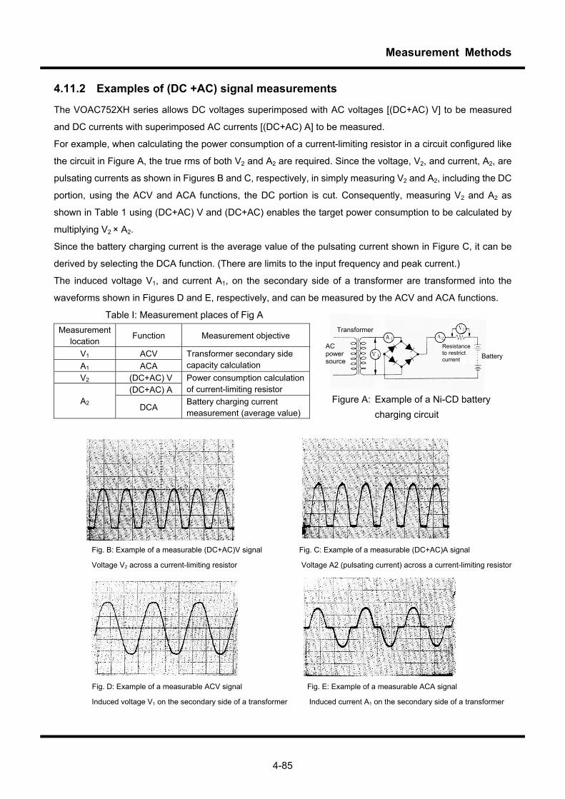
Measurement Methods
4-85
4.11.2 Examples of (DC +AC) signal measurements
The VOAC752XH series allows DC voltages superimposed with AC voltages [(DC+AC) V] to be measured
and DC currents with superimposed AC currents [(DC+AC) A] to be measured.
For example, when calculating the power consumption of a current-limiting resistor in a circuit configured like
the circuit in Figure A, the true rms of both V2 and A2 are required. Since the voltage, V2, and current, A2, are
pulsating currents as shown in Figures B and C, respectively, in simply measuring V2 and A2, including the DC
portion, using the ACV and ACA functions, the DC portion is cut. Consequently, measuring V2 and A2 as
shown in Table 1 using (DC+AC) V and (DC+AC) enables the target power consumption to be calculated by
multiplying V2 × A2.
Since the battery charging current is the average value of the pulsating current shown in Figure C, it can be
derived by selecting the DCA function. (There are limits to the input frequency and peak current.)
The induced voltage V1, and current A1, on the secondary side of a transformer are transformed into the
waveforms shown in Figures D and E, respectively, and can be measured by the ACV and ACA functions.
Table I: Measurement places of Fig A Measurement
location Function Measurement objective
V1 ACV A1 ACA
Transformer secondary side capacity calculation
V2 (DC+AC) V (DC+AC) A
Power consumption calculation of current-limiting resistor
A2 DCA Battery charging current measurement (average value)
Fig. B: Example of a measurable (DC+AC)V signal Fig. C: Example of a measurable (DC+AC)A signal Voltage V2 across a current-limiting resistor Voltage A2 (pulsating current) across a current-limiting resistor
Fig. D: Example of a measurable ACV signal Fig. E: Example of a measurable ACA signal Induced voltage V1 on the secondary side of a transformer Induced current A1 on the secondary side of a transformer
Battery
Transformer
AC power source
Resistance to restrict current
Figure A: Example of a Ni-CD battery charging circuit
Measurement Methods
4-86
Memo
Specifications Examination and Calibration
1234567
Chapter 5 Specifications Examination and Calibration
Specifications Examination and Calibration
5-2
5.1 Overview In order to carry out accurate measurement, it is necessary to maintain a high level of measurement accuracy for the device. Carrying out periodic examinations and calibrations of the multimeter means it is possible to ensure reliable measurements. This chapter explains these examination and calibration methods.
5.1.1 Period for examination and calibration
In order to carry out accurate measurement, it is necessary to implement periodic examination and calibration of the instrument. Once per year is a suitable frequency for the multimeter when under normal usage conditions. After calibration has been completed, it is convenient to specify on a card or a sticker the date this was carried out, and the time for the next correction. Furthermore, the expected lifespan of the backup battery is more than five years at normal temperatures. The battery can not be replaced by users. Please contact an Iwatsu service center.
5.1.2 Reminders before carrying out examination and calibration
・Carry out inspections or calibrations with the device properly set up. ・ Please confirm that the power supply voltage is within ±10% of the value written on the back panel, and
that the frequency of the power supply is either 50Hz or 60Hz. ・ Please carry out normal calibration in an environment which has a temperature of 23°C±5°C, and a
humidity level of under 80%RH. ・ Please carry out a warm up for at least one hour after turning the power supply on. ・ When carrying out correction, please use the included adjustment driver. ・ The multimeter uses copper input terminals. The use of leads that are made of different materials (e.g.
steel) will lead to a thermal electromotive source, therefore ensure you use copper wiring for standard output cabling (signal output). Failure to do so can lead to correction errors in the 500mV range.
・ With certain exceptions, the multimeter records correction data in internal memory, and employs a micro CPU calculation software correction system. Accordingly, if the internal correction data is destroyed as a result of incorrect operation, then accurate measurement will not be possible. Please take care when operating the device.
・ Equipment required for correction is displayed in Table 5-1. Additionally, ensure that you use either the devices displayed, or those with higher capabilities.
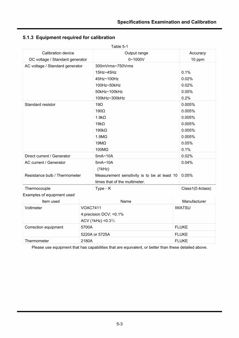
Specifications Examination and Calibration
5-3
5.1.3 Equipment required for calibration
Table 5-1 Calibration device Output range Accuracy
DC voltage / Standard generator 0~1000V 10 ppm AC voltage / Standard generator 300mVrms~750Vrms
15Hz~45Hz 45Hz~100Hz 100Hz~50kHz 50kHz~100kHz 100kHz~300kHz
0.1% 0.02% 0.02% 0.05% 0.2%
Standard resistor 19Ω 190Ω 1.9kΩ 19kΩ 190kΩ 1.9MΩ 19MΩ 100MΩ
0.005% 0.005% 0.005% 0.005% 0.005% 0.005% 0.05% 0.1%
Direct current / Generator 5mA~10A 0.02% AC current / Generator 5mA~10A
(1kHz) 0.04%
Resistance bulb / Thermometer Measurement sensitivity is to be at least 10 times that of the multimeter.
0.05%
Thermocouple Type-K Class1(0.4class) Examples of equipment used
Item used Name Manufacturer Voltmeter VOAC7411
4:precision DCV; <0.1% ACV (1kHz) <0.3%
IWATSU
5700A FLUKE Correction equipment
5220A or 5725A FLUKE Thermometer 2180A FLUKE
Please use equipment that has capabilities that are equivalent, or better than these detailed above.
Specifications Examination and Calibration
5-4
5.1.4 Calibration items and basic calibration procedures
5.1.4.1 DCV, CH-B DCV, DCA, 2WΩ, 4WΩ function 1. Zero calibration (Software calibration)
2. Full scale calibration (Software calibration) 3. Examination 4. Completion <Note 1> CH-B DCV is only available on the VOAC7520H/7523H. <Note 2> 4WΩ is only available on the VOAC7521/7522H.
5.1.4.2 ACV function 1. Minimum input calibration (software calibration) 2. Full scale calibration (Software calibration) 3. Calibration of frequency characteristics 4. Examination 5. Completion
5.1.4.3 ACA, function 1. Minimum input calibration (software calibration) 2. Full scale calibration (Software calibration) 3. Examination
4. Completion <Note> Please carry out full scale calibration for the ACA function after calibration of the ACV function has
been completed.
5.1.4.4 °C, Hz function 1. Corrected by the specified temperature or specified frequency (software calibration) 2. Examination
3. Completion
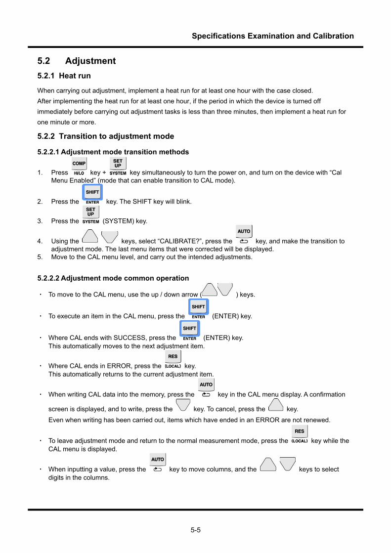
Specifications Examination and Calibration
5-5
5.2 Adjustment 5.2.1 Heat run
When carrying out adjustment, implement a heat run for at least one hour with the case closed. After implementing the heat run for at least one hour, if the period in which the device is turned off immediately before carrying out adjustment tasks is less than three minutes, then implement a heat run for one minute or more.
5.2.2 Transition to adjustment mode
5.2.2.1 Adjustment mode transition methods
1. Press key + key simultaneously to turn the power on, and turn on the device with “Cal Menu Enabled” (mode that can enable transition to CAL mode).
2. Press the key. The SHIFT key will blink.
3. Press the (SYSTEM) key.
4. Using the keys, select “CALIBRATE?”, press the key, and make the transition to adjustment mode. The last menu items that were corrected will be displayed.
5. Move to the CAL menu level, and carry out the intended adjustments.
5.2.2.2 Adjustment mode common operation
・ To move to the CAL menu, use the up / down arrow ( ) keys.
・ To execute an item in the CAL menu, press the (ENTER) key.
・ Where CAL ends with SUCCESS, press the (ENTER) key. This automatically moves to the next adjustment item.
・ Where CAL ends in ERROR, press the key. This automatically returns to the current adjustment item.
・ When writing CAL data into the memory, press the key in the CAL menu display. A confirmation
screen is displayed, and to write, press the key. To cancel, press the key.
Even when writing has been carried out, items which have ended in an ERROR are not renewed.
・ To leave adjustment mode and return to the normal measurement mode, press the key while the CAL menu is displayed.
・ When inputting a value, press the key to move columns, and the keys to select digits in the columns.
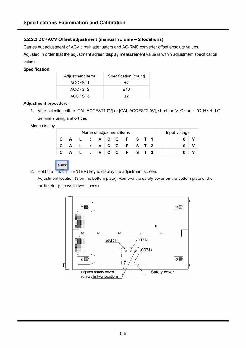
Specifications Examination and Calibration
5-6
5.2.2.3 DC+ACV Offset adjustment (manual volume – 2 locations) Carries out adjustment of ACV circuit attenuators and AC-RMS converter offset absolute values.
Adjusted in order that the adjustment screen display measurement value is within adjustment specification
values.
Specification Adjustment items Specification [count]
ACOFST1 ±2 ACOFST2 ±10 ACOFST3 ±2
Adjustment procedure
1. After selecting either [CAL:ACOFST1 0V] or [CAL:ACOFST2 0V], short the V・Ω・ ・ °C・Hz HI-LO
terminals using a short bar.
Menu display Name of adjustment items Input voltage
C A L : A C O F S T 1 0 V C A L : A C O F S T 2 0 V C A L : A C O F S T 3 0 V
2. Hold the (ENTER) key to display the adjustment screen. Adjustment location (3 on the bottom plate): Remove the safety cover on the bottom plate of the
multimeter (screws in two places).
Tighten safety cover screws in two locations
Safety cover
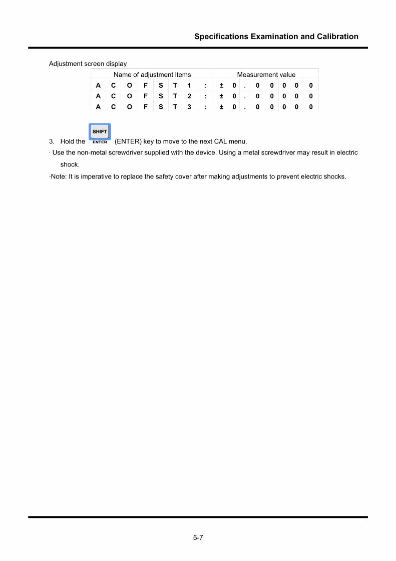
Specifications Examination and Calibration
5-7
Adjustment screen display Name of adjustment items Measurement value
A C O F S T 1 : ± 0 . 0 0 0 0 0 A C O F S T 2 : ± 0 . 0 0 0 0 0 A C O F S T 3 : ± 0 . 0 0 0 0 0
3. Hold the (ENTER) key to move to the next CAL menu. ·Use the non-metal screwdriver supplied with the device. Using a metal screwdriver may result in electric
shock.
·Note: It is imperative to replace the safety cover after making adjustments to prevent electric shocks.
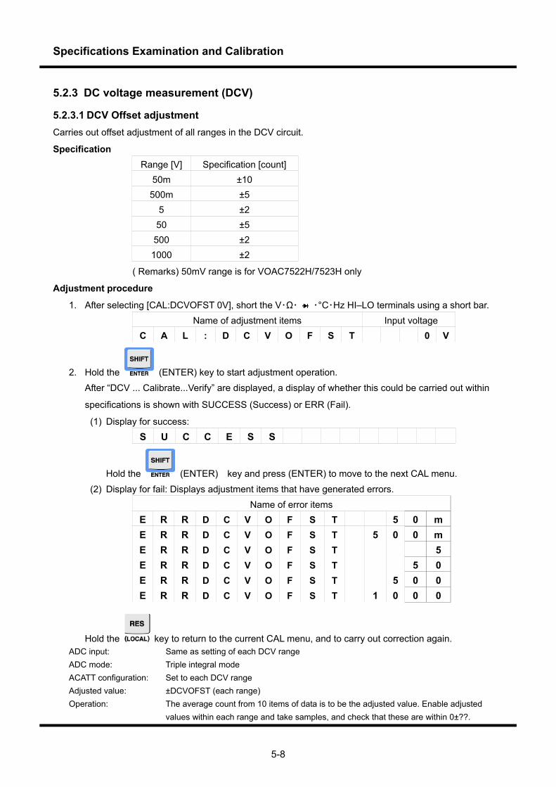
Specifications Examination and Calibration
5-8
5.2.3 DC voltage measurement (DCV)
5.2.3.1 DCV Offset adjustment Carries out offset adjustment of all ranges in the DCV circuit.
Specification Range [V] Specification [count]
50m ±10 500m ±5
5 ±2 50 ±5
500 ±2 1000 ±2
( Remarks) 50mV range is for VOAC7522H/7523H only
Adjustment procedure
1. After selecting [CAL:DCVOFST 0V], short the V・Ω・ ・°C・Hz HI–LO terminals using a short bar. Name of adjustment items Input voltage
C A L : D C V O F S T 0 V
2. Hold the (ENTER) key to start adjustment operation. After “DCV ... Calibrate...Verify” are displayed, a display of whether this could be carried out within
specifications is shown with SUCCESS (Success) or ERR (Fail).
(1) Display for success: S U C C E S S
Hold the (ENTER) key and press (ENTER) to move to the next CAL menu. (2) Display for fail: Displays adjustment items that have generated errors.
Name of error items E R R D C V O F S T 5 0 m E R R D C V O F S T 5 0 0 m E R R D C V O F S T 5 E R R D C V O F S T 5 0 E R R D C V O F S T 5 0 0 E R R D C V O F S T 1 0 0 0
Hold the key to return to the current CAL menu, and to carry out correction again. ADC input: Same as setting of each DCV range ADC mode: Triple integral mode ACATT configuration: Set to each DCV range Adjusted value: ±DCVOFST (each range) Operation: The average count from 10 items of data is to be the adjusted value. Enable adjusted
values within each range and take samples, and check that these are within 0±??.
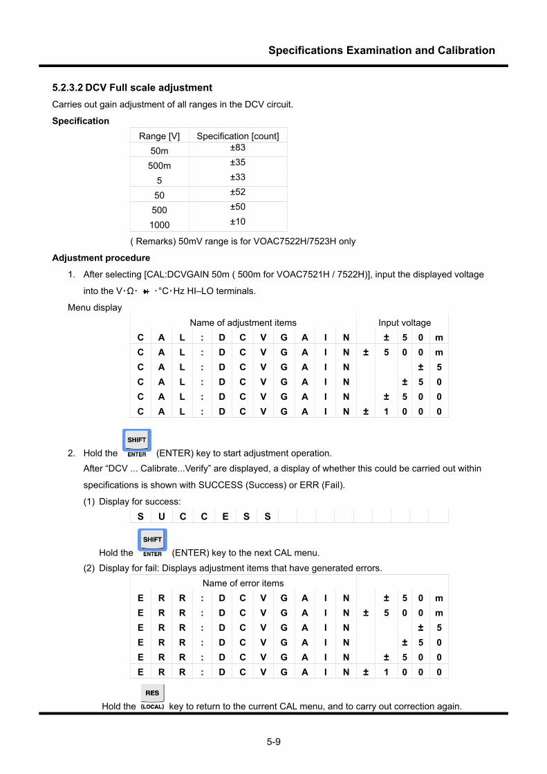
Specifications Examination and Calibration
5-9
5.2.3.2 DCV Full scale adjustment Carries out gain adjustment of all ranges in the DCV circuit.
Specification Range [V] Specification [count]
50m ±83
500m ±35
5 ±33
50 ±52
500 ±50
1000 ±10
( Remarks) 50mV range is for VOAC7522H/7523H only
Adjustment procedure
1. After selecting [CAL:DCVGAIN 50m ( 500m for VOAC7521H / 7522H)], input the displayed voltage
into the V・Ω・ ・°C・Hz HI–LO terminals.
Menu display Name of adjustment items Input voltage
C A L : D C V G A I N ± 5 0 m C A L : D C V G A I N ± 5 0 0 m C A L : D C V G A I N ± 5 C A L : D C V G A I N ± 5 0 C A L : D C V G A I N ± 5 0 0 C A L : D C V G A I N ± 1 0 0 0
2. Hold the (ENTER) key to start adjustment operation. After “DCV ... Calibrate...Verify” are displayed, a display of whether this could be carried out within
specifications is shown with SUCCESS (Success) or ERR (Fail).
(1) Display for success: S U C C E S S
Hold the (ENTER) key to the next CAL menu. (2) Display for fail: Displays adjustment items that have generated errors.
Name of error items E R R : D C V G A I N ± 5 0 m E R R : D C V G A I N ± 5 0 0 m E R R : D C V G A I N ± 5 E R R : D C V G A I N ± 5 0 E R R : D C V G A I N ± 5 0 0 E R R : D C V G A I N ± 1 0 0 0
Hold the key to return to the current CAL menu, and to carry out correction again.
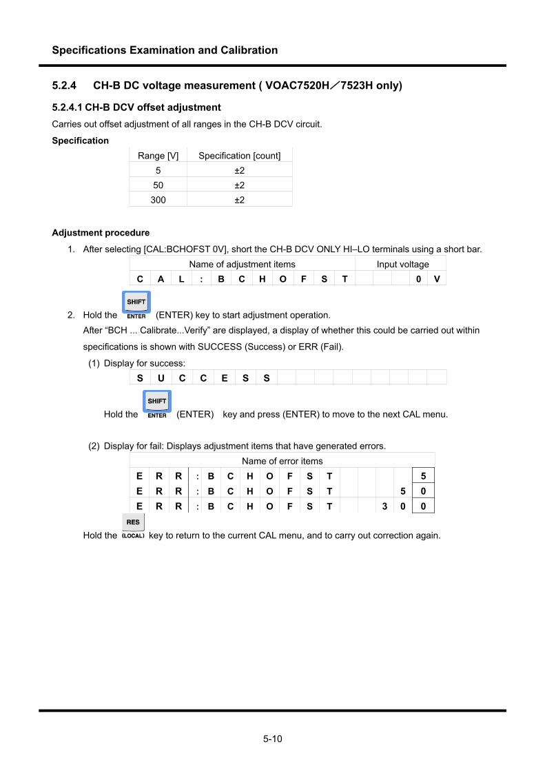
Specifications Examination and Calibration
5-10
5.2.4 CH-B DC voltage measurement ( VOAC7520H/7523H only)
5.2.4.1 CH-B DCV offset adjustment Carries out offset adjustment of all ranges in the CH-B DCV circuit.
Specification Range [V] Specification [count]
5 ±2 50 ±2
300 ±2
Adjustment procedure
1. After selecting [CAL:BCHOFST 0V], short the CH-B DCV ONLY HI–LO terminals using a short bar. Name of adjustment items Input voltage
C A L : B C H O F S T 0 V
2. Hold the (ENTER) key to start adjustment operation. After “BCH ... Calibrate...Verify” are displayed, a display of whether this could be carried out within
specifications is shown with SUCCESS (Success) or ERR (Fail).
(1) Display for success: S U C C E S S
Hold the (ENTER) key and press (ENTER) to move to the next CAL menu.
(2) Display for fail: Displays adjustment items that have generated errors.
Name of error items E R R : B C H O F S T 5 E R R : B C H O F S T 5 0 E R R : B C H O F S T 3 0 0
Hold the key to return to the current CAL menu, and to carry out correction again.
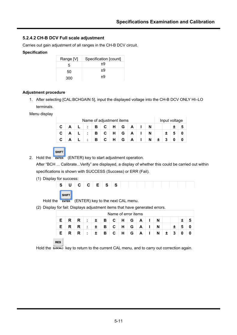
Specifications Examination and Calibration
5-11
5.2.4.2 CH-B DCV Full scale adjustment Carries out gain adjustment of all ranges in the CH-B DCV circuit.
Specification Range [V] Specification [count]
5 ±9
50 ±9
300 ±9
Adjustment procedure
1. After selecting [CAL:BCHGAIN 5], input the displayed voltage into the CH-B DCV ONLY HI–LO
terminals.
Menu display Name of adjustment items Input voltage
C A L : B C H G A I N ± 5 C A L : B C H G A I N ± 5 0 C A L : B C H G A I N ± 3 0 0
2. Hold the (ENTER) key to start adjustment operation. After “BCH ... Calibrate...Verify” are displayed, a display of whether this could be carried out within
specifications is shown with SUCCESS (Success) or ERR (Fail).
(1) Display for success: S U C C E S S
Hold the (ENTER) key to the next CAL menu. (2) Display for fail: Displays adjustment items that have generated errors.
Name of error items E R R : ± B C H G A I N ± 5 E R R : ± B C H G A I N ± 5 0 E R R : ± B C H G A I N ± 3 0 0
Hold the key to return to the current CAL menu, and to carry out correction again.
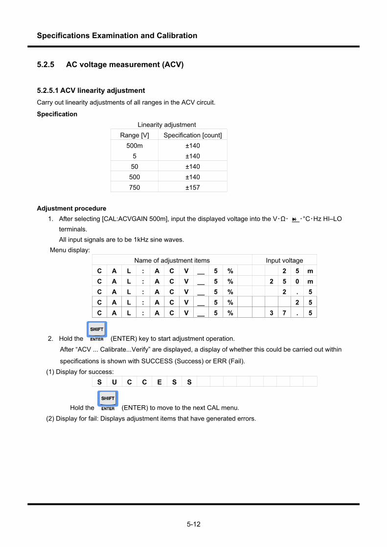
Specifications Examination and Calibration
5-12
5.2.5 AC voltage measurement (ACV)
5.2.5.1 ACV linearity adjustment Carry out linearity adjustments of all ranges in the ACV circuit.
Specification Linearity adjustment
Range [V] Specification [count]500m ±140
5 ±140 50 ±140 500 ±140 750 ±157
Adjustment procedure
1. After selecting [CAL:ACVGAIN 500m], input the displayed voltage into the V・Ω・ ・°C・Hz HI–LO terminals.
All input signals are to be 1kHz sine waves. Menu display:
Name of adjustment items Input voltage C A L : A C V __ 5 % 2 5 m C A L : A C V __ 5 % 2 5 0 m C A L : A C V __ 5 % 2 . 5 C A L : A C V __ 5 % 2 5 C A L : A C V __ 5 % 3 7 . 5
2. Hold the (ENTER) key to start adjustment operation.
After “ACV ... Calibrate...Verify” are displayed, a display of whether this could be carried out within
specifications is shown with SUCCESS (Success) or ERR (Fail). (1) Display for success:
S U C C E S S
Hold the (ENTER) to move to the next CAL menu. (2) Display for fail: Displays adjustment items that have generated errors.
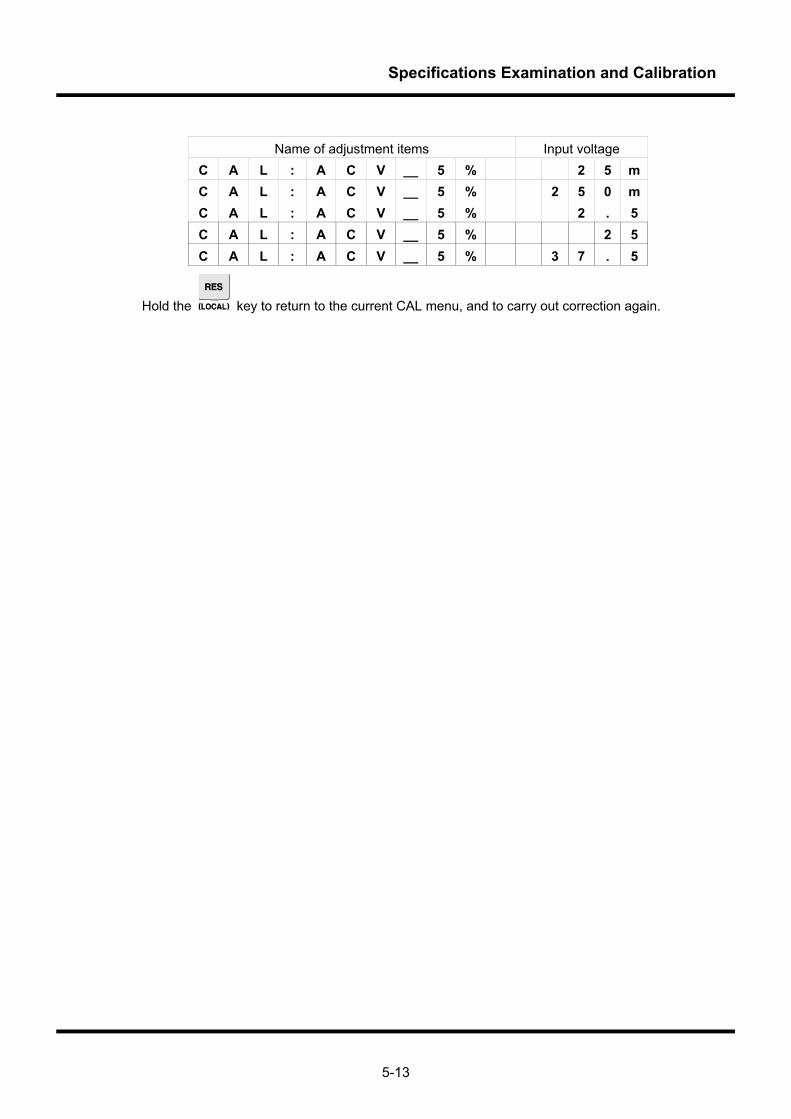
Specifications Examination and Calibration
5-13
Name of adjustment items Input voltage
C A L : A C V __ 5 % 2 5 m C A L : A C V __ 5 % 2 5 0 m C A L : A C V __ 5 % 2 . 5 C A L : A C V __ 5 % 2 5 C A L : A C V __ 5 % 3 7 . 5
Hold the key to return to the current CAL menu, and to carry out correction again.
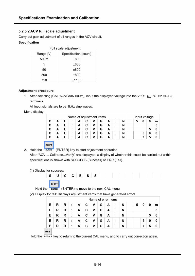
Specifications Examination and Calibration
5-14
5.2.5.2 ACV full scale adjustment Carry out gain adjustment of all ranges in the ACV circuit.
Specification
Full scale adjustment Range [V] Specification [count]
500m ±800 5 ±800 50 ±800
500 ±800 750 ±1155
Adjustment procedure
1. After selecting [CAL:ACVGAIN 500m], input the displayed voltage into the V・Ω・ ・°C・Hz HI–LO terminals.
All input signals are to be 1kHz sine waves. Menu display:
Name of adjustment items Input voltage C A L : A C V G A I N 5 0 0 m C A L : A C V G A I N 5 C A L : A C V G A I N 5 0 C A L : A C V G A I N 5 0 0 C A L : A C V G A I N 7 5 0
2. Hold the (ENTER) key to start adjustment operation. After “ACV ... Calibrate...Verify” are displayed, a display of whether this could be carried out within
specifications is shown with SUCCESS (Success) or ERR (Fail).
(1) Display for success: S U C C E S S
Hold the (ENTER) to move to the next CAL menu. (2) Display for fail: Displays adjustment items that have generated errors.
Name of error items E R R : A C V G A I N 5 0 0 m E R R : A C V G A I N 5 E R R : A C V G A I N 5 0 E R R : A C V G A I N 5 0 0 E R R : A C V G A I N 7 5 0
Hold the key to return to the current CAL menu, and to carry out correction again.
Specifications Examination and Calibration
5-15
ADC input: AC ATT OUT ADC mode: Triple integral mode ACACATT configuration: Set to each ACV range ACSEL configuration: ACSEL[1..0] = 0 Adjusted value: ±ACVOFST (each range) Operation: The average count from 10 items of data is to be the adjusted value. Enable adjusted
values within each range and take samples, and check that these are within adjustment specifications. Some ranges may be measured by using averages.

Specifications Examination and Calibration
5-16
5.2.5.3 Frequency characteristics adjustment Carry out frequency characteristics adjustment of all ranges in the ACV circuit. Adjustment procedure
1. After selecting [CAL:ACVHF1 500m], input the displayed voltage between the V・Ω・ ・°C・Hz HI–LO terminals. All input signals are to be 100kHz sine waves.
2. Hold the key and press (ENTER) to display the adjustment screen. 3. Vary the adjusted value using the up and down arrow buttons, and adjust in order that the
measurement value is within ±1750 of the count. Menu display:
Name of adjustment items Input voltage C A L : A C V H F 1 5 0 0 m C A L : A C V H F 2 5 C A L : A C V H F 3 5 0 C A L : A C V H F 4 5 0 0 C A L : A C V H F 5 5 0 0
4. Hold the key and press (ENTER) to move to the adjusted value input screen. Adjusted value input screen display:
Name of adjustment items Measurement value Adjusted valueA C H F 1 5 0 0 . 0 0 0 6 3 A C H F 2 5 . 0 0 0 0 0 6 3 A C H F 3 5 0 . 0 0 0 0 6 3 A C H F 4 5 0 0 . 0 0 0 6 3 A C H F 5 5 0 0 . 0 0 0 6 3
5. Hold the keys to change the adjusted value.
6. Hold down the key to return to the current CAL menu.
7. Hold the key and press (ENTER) to set the current CAL, and to move to the next CAL menu. (1) Display for success:
S U C C E S S
Hold the key and press (ENTER) to move to the next CAL menu. (2) Display for fail: Displays adjustment items that have generated errors.
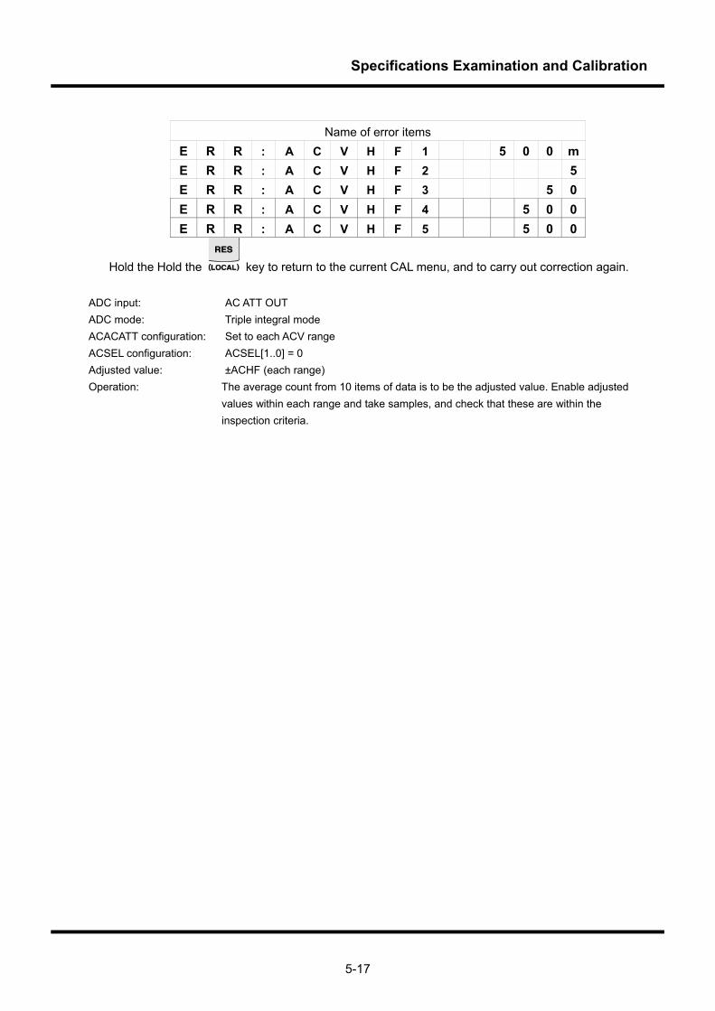
Specifications Examination and Calibration
5-17
Name of error items
E R R : A C V H F 1 5 0 0 m E R R : A C V H F 2 5 E R R : A C V H F 3 5 0 E R R : A C V H F 4 5 0 0 E R R : A C V H F 5 5 0 0
Hold the Hold the key to return to the current CAL menu, and to carry out correction again. ADC input: AC ATT OUT ADC mode: Triple integral mode ACACATT configuration: Set to each ACV range ACSEL configuration: ACSEL[1..0] = 0 Adjusted value: ±ACHF (each range) Operation: The average count from 10 items of data is to be the adjusted value. Enable adjusted
values within each range and take samples, and check that these are within the inspection criteria.
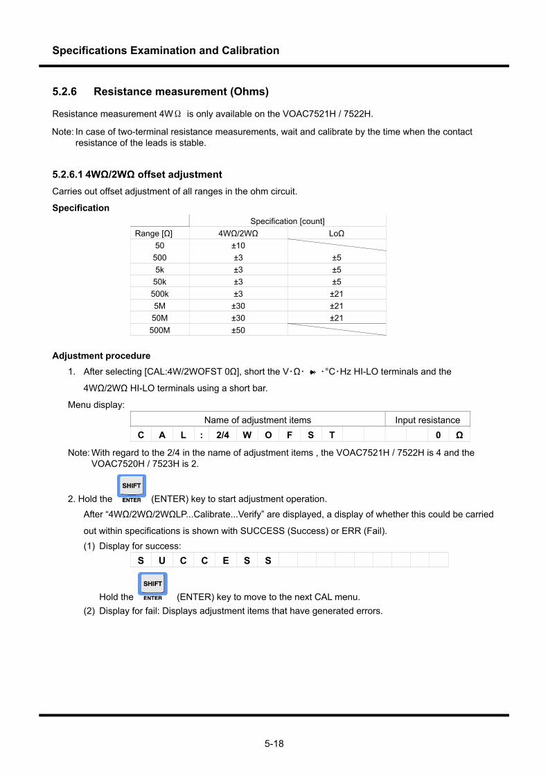
Specifications Examination and Calibration
5-18
5.2.6 Resistance measurement (Ohms)
Resistance measurement 4WΩ is only available on the VOAC7521H / 7522H.
Note: In case of two-terminal resistance measurements, wait and calibrate by the time when the contact resistance of the leads is stable.
5.2.6.1 4WΩ/2WΩ offset adjustment Carries out offset adjustment of all ranges in the ohm circuit.
Specification Specification [count] Range [Ω] 4WΩ/2WΩ LoΩ
50 ±10 500 ±3 ±5 5k ±3 ±5
50k ±3 ±5 500k ±3 ±21 5M ±30 ±21
50M ±30 ±21 500M ±50
Adjustment procedure
1. After selecting [CAL:4W/2WOFST 0Ω], short the V・Ω・ ・°C・Hz HI-LO terminals and the
4WΩ/2WΩ HI-LO terminals using a short bar.
Menu display: Name of adjustment items Input resistance
C A L : 2/4 W O F S T 0 Ω
Note: With regard to the 2/4 in the name of adjustment items , the VOAC7521H / 7522H is 4 and the VOAC7520H / 7523H is 2.
2. Hold the (ENTER) key to start adjustment operation.
After “4WΩ/2WΩ/2WΩLP...Calibrate...Verify” are displayed, a display of whether this could be carried
out within specifications is shown with SUCCESS (Success) or ERR (Fail). (1) Display for success:
S U C C E S S
Hold the (ENTER) key to move to the next CAL menu. (2) Display for fail: Displays adjustment items that have generated errors.
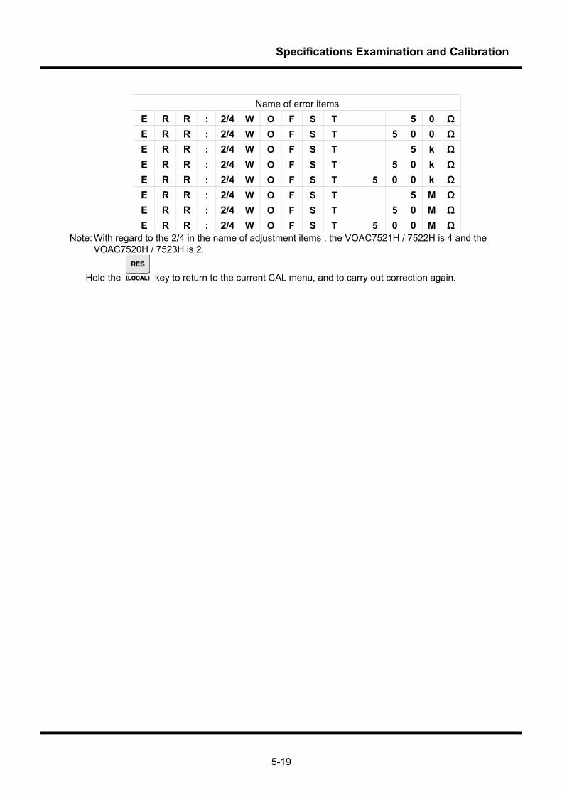
Specifications Examination and Calibration
5-19
Name of error items
E R R : 2/4 W O F S T 5 0 Ω E R R : 2/4 W O F S T 5 0 0 Ω E R R : 2/4 W O F S T 5 k Ω E R R : 2/4 W O F S T 5 0 k Ω E R R : 2/4 W O F S T 5 0 0 k Ω E R R : 2/4 W O F S T 5 M Ω E R R : 2/4 W O F S T 5 0 M Ω E R R : 2/4 W O F S T 5 0 0 M Ω
Note: With regard to the 2/4 in the name of adjustment items , the VOAC7521H / 7522H is 4 and the VOAC7520H / 7523H is 2.
Hold the key to return to the current CAL menu, and to carry out correction again.
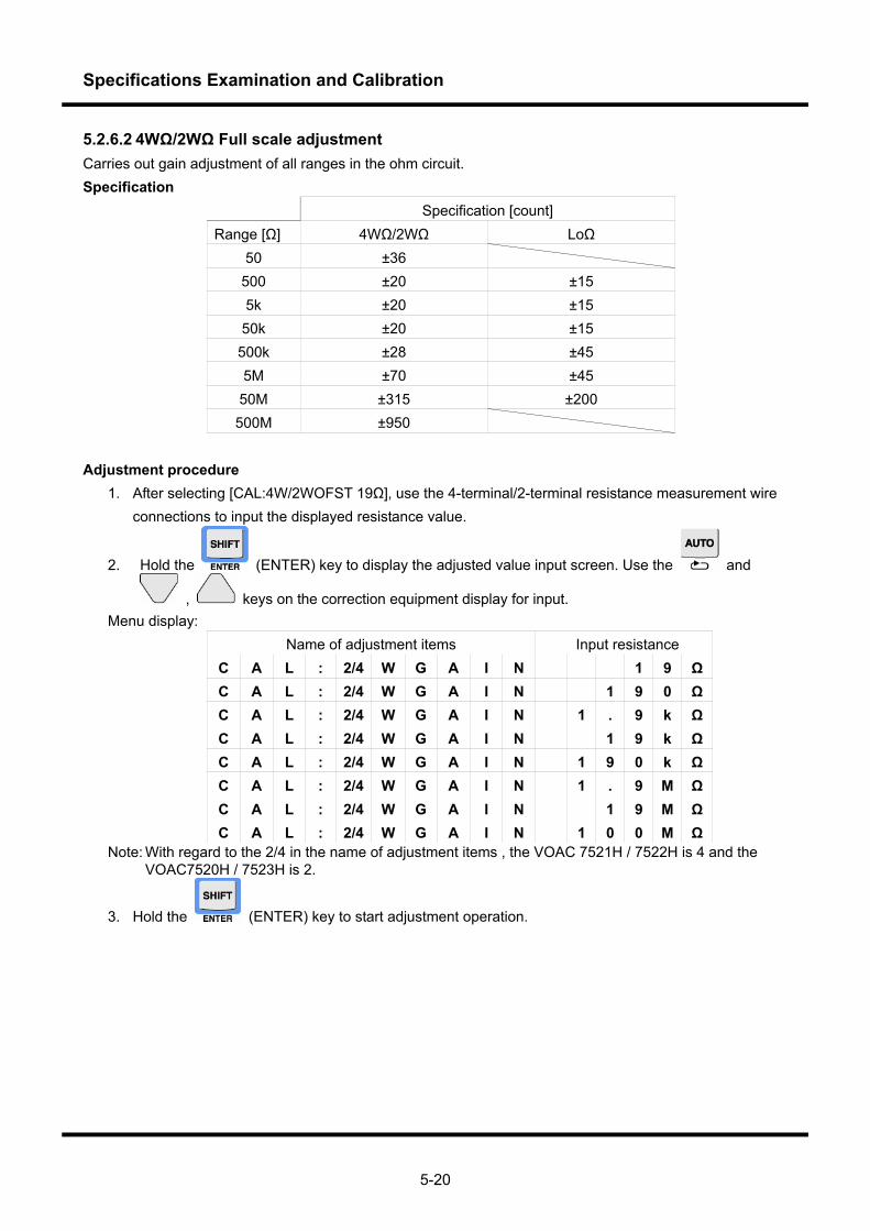
Specifications Examination and Calibration
5-20
5.2.6.2 4WΩ/2WΩ Full scale adjustment Carries out gain adjustment of all ranges in the ohm circuit. Specification
Specification [count] Range [Ω] 4WΩ/2WΩ LoΩ
50 ±36 500 ±20 ±15 5k ±20 ±15 50k ±20 ±15 500k ±28 ±45 5M ±70 ±45
50M ±315 ±200 500M ±950
Adjustment procedure
1. After selecting [CAL:4W/2WOFST 19Ω], use the 4-terminal/2-terminal resistance measurement wire connections to input the displayed resistance value.
2. Hold the (ENTER) key to display the adjusted value input screen. Use the and
, keys on the correction equipment display for input. Menu display:
Name of adjustment items Input resistance C A L : 2/4 W G A I N 1 9 Ω C A L : 2/4 W G A I N 1 9 0 Ω C A L : 2/4 W G A I N 1 . 9 k Ω C A L : 2/4 W G A I N 1 9 k Ω C A L : 2/4 W G A I N 1 9 0 k Ω C A L : 2/4 W G A I N 1 . 9 M Ω C A L : 2/4 W G A I N 1 9 M Ω C A L : 2/4 W G A I N 1 0 0 M Ω
Note: With regard to the 2/4 in the name of adjustment items , the VOAC 7521H / 7522H is 4 and the VOAC7520H / 7523H is 2.
3. Hold the (ENTER) key to start adjustment operation.
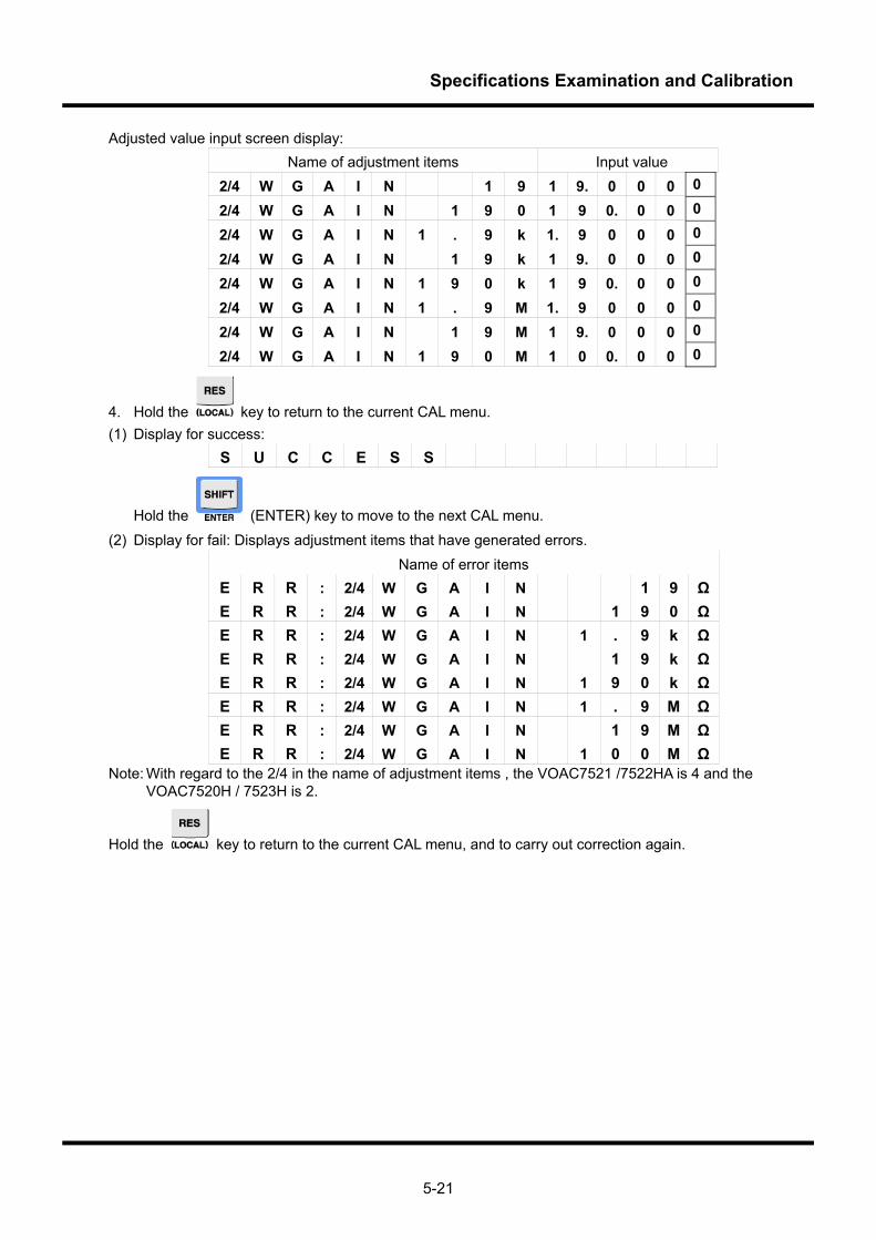
Specifications Examination and Calibration
5-21
Adjusted value input screen display: Name of adjustment items Input value
2/4 W G A I N 1 9 1 9. 0 0 0 0
2/4 W G A I N 1 9 0 1 9 0. 0 0 0
2/4 W G A I N 1 . 9 k 1. 9 0 0 0 0
2/4 W G A I N 1 9 k 1 9. 0 0 0 0
2/4 W G A I N 1 9 0 k 1 9 0. 0 0 0
2/4 W G A I N 1 . 9 M 1. 9 0 0 0 0
2/4 W G A I N 1 9 M 1 9. 0 0 0 0
2/4 W G A I N 1 9 0 M 1 0 0. 0 0 0
4. Hold the key to return to the current CAL menu. (1) Display for success:
S U C C E S S
Hold the (ENTER) key to move to the next CAL menu.
(2) Display for fail: Displays adjustment items that have generated errors. Name of error items
E R R : 2/4 W G A I N 1 9 Ω E R R : 2/4 W G A I N 1 9 0 Ω E R R : 2/4 W G A I N 1 . 9 k Ω E R R : 2/4 W G A I N 1 9 k Ω E R R : 2/4 W G A I N 1 9 0 k Ω E R R : 2/4 W G A I N 1 . 9 M Ω E R R : 2/4 W G A I N 1 9 M Ω E R R : 2/4 W G A I N 1 0 0 M Ω
Note: With regard to the 2/4 in the name of adjustment items , the VOAC7521 /7522HA is 4 and the VOAC7520H / 7523H is 2.
Hold the key to return to the current CAL menu, and to carry out correction again.
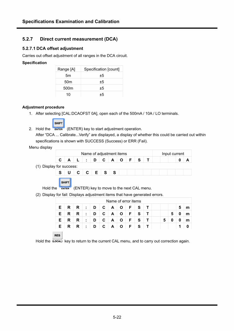
Specifications Examination and Calibration
5-22
5.2.7 Direct current measurement (DCA)
5.2.7.1 DCA offset adjustment Carries out offset adjustment of all ranges in the DCA circuit.
Specification Range [A] Specification [count]
5m ±5 50m ±5 500m ±5
10 ±5 Adjustment procedure
1. After selecting [CAL:DCAOFST 0A], open each of the 500mA / 10A / LO terminals.
2. Hold the (ENTER) key to start adjustment operation. After “DCA ... Calibrate...Verify” are displayed, a display of whether this could be carried out within
specifications is shown with SUCCESS (Success) or ERR (Fail). Menu display
Name of adjustment items Input current C A L : D C A O F S T 0 A
(1) Display for success: S U C C E S S
Hold the (ENTER) key to move to the next CAL menu. (2) Display for fail: Displays adjustment items that have generated errors.
Name of error items E R R : D C A O F S T 5 m E R R : D C A O F S T 5 0 m E R R : D C A O F S T 5 0 0 m E R R : D C A O F S T 1 0
Hold the key to return to the current CAL menu, and to carry out correction again.
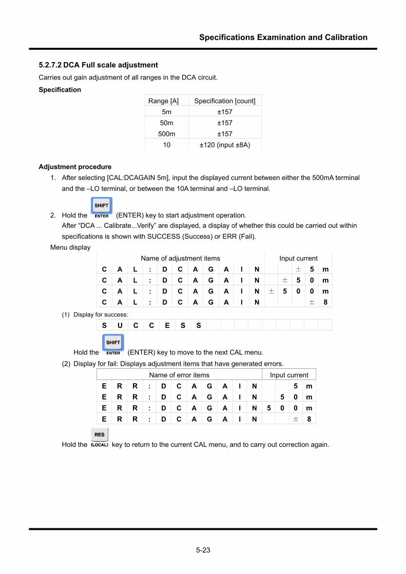
Specifications Examination and Calibration
5-23
5.2.7.2 DCA Full scale adjustment Carries out gain adjustment of all ranges in the DCA circuit.
Specification Range [A] Specification [count]
5m ±157 50m ±157 500m ±157
10 ±120 (input ±8A) Adjustment procedure
1. After selecting [CAL:DCAGAIN 5m], input the displayed current between either the 500mA terminal and the –LO terminal, or between the 10A terminal and –LO terminal.
2. Hold the (ENTER) key to start adjustment operation. After “DCA ... Calibrate...Verify” are displayed, a display of whether this could be carried out within
specifications is shown with SUCCESS (Success) or ERR (Fail). Menu display
Name of adjustment items Input current C A L : D C A G A I N ± 5 m C A L : D C A G A I N ± 5 0 m C A L : D C A G A I N ± 5 0 0 m C A L : D C A G A I N ± 8
(1) Display for success:
S U C C E S S
Hold the (ENTER) key to move to the next CAL menu.
(2) Display for fail: Displays adjustment items that have generated errors. Name of error items Input current
E R R : D C A G A I N 5 m E R R : D C A G A I N 5 0 m E R R : D C A G A I N 5 0 0 m E R R : D C A G A I N ± 8
Hold the key to return to the current CAL menu, and to carry out correction again.
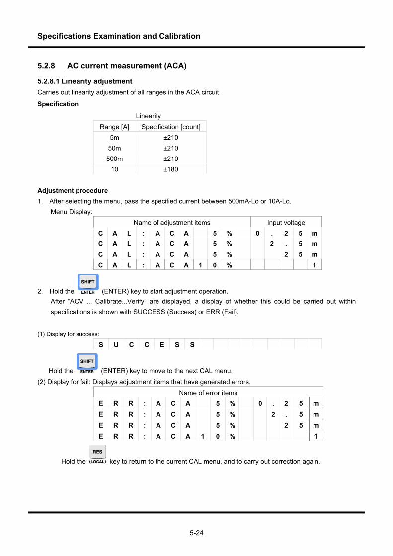
Specifications Examination and Calibration
5-24
5.2.8 AC current measurement (ACA)
5.2.8.1 Linearity adjustment Carries out linearity adjustment of all ranges in the ACA circuit.
Specification
Linearity Range [A] Specification [count]
5m ±210 50m ±210 500m ±210
10 ±180 Adjustment procedure 1. After selecting the menu, pass the specified current between 500mA-Lo or 10A-Lo.
Menu Display: Name of adjustment items Input voltage
C A L : A C A 5 % 0 . 2 5 m C A L : A C A 5 % 2 . 5 m C A L : A C A 5 % 2 5 m C A L : A C A 1 0 % 1
2. Hold the (ENTER) key to start adjustment operation. After “ACV ... Calibrate...Verify” are displayed, a display of whether this could be carried out within specifications is shown with SUCCESS (Success) or ERR (Fail).
(1) Display for success:
S U C C E S S
Hold the (ENTER) key to move to the next CAL menu. (2) Display for fail: Displays adjustment items that have generated errors.
Name of error items E R R : A C A 5 % 0 . 2 5 m E R R : A C A 5 % 2 . 5 m E R R : A C A 5 % 2 5 m E R R : A C A 1 0 % 1
Hold the key to return to the current CAL menu, and to carry out correction again.
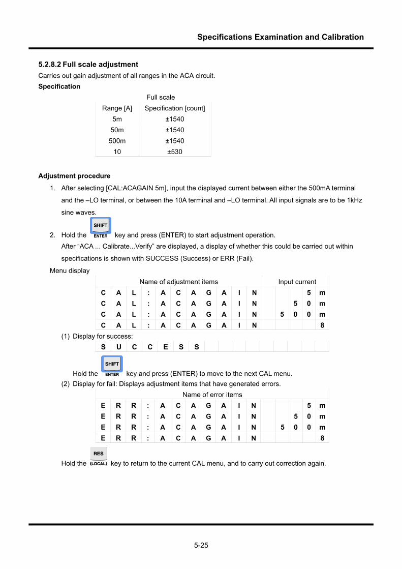
Specifications Examination and Calibration
5-25
5.2.8.2 Full scale adjustment Carries out gain adjustment of all ranges in the ACA circuit. Specification Full scale
Range [A] Specification [count]5m ±1540
50m ±1540 500m ±1540
10 ±530
Adjustment procedure
1. After selecting [CAL:ACAGAIN 5m], input the displayed current between either the 500mA terminal
and the –LO terminal, or between the 10A terminal and –LO terminal. All input signals are to be 1kHz
sine waves.
2. Hold the key and press (ENTER) to start adjustment operation. After “ACA ... Calibrate...Verify” are displayed, a display of whether this could be carried out within
specifications is shown with SUCCESS (Success) or ERR (Fail).
Menu display Name of adjustment items Input current
C A L : A C A G A I N 5 m C A L : A C A G A I N 5 0 m C A L : A C A G A I N 5 0 0 m C A L : A C A G A I N 8
(1) Display for success: S U C C E S S
Hold the key and press (ENTER) to move to the next CAL menu. (2) Display for fail: Displays adjustment items that have generated errors.
Name of error items E R R : A C A G A I N 5 m E R R : A C A G A I N 5 0 m E R R : A C A G A I N 5 0 0 m E R R : A C A G A I N 8
Hold the key to return to the current CAL menu, and to carry out correction again.

Specifications Examination and Calibration
5-26
5.2.9 Temperature measurement (TEMP)
5.2.9.1 Temperature adjustment Carries out adjustment of the temperature measurement circuit. Specification Adjusted value
Thermocouple type Indicated value on the correction equipment K ±1.0°C
Adjustment procedure
1. After selecting [CAL:TEMP TC-K], connect the displayed thermocouple between the V・Ω・ ・°C・Hz HI-LO terminals.
Connect the thermocouple as in the diagram, and equalize the temperature.
2. Hold the (ENTER) key, and the adjusted value input screen is displayed, and then input the temperature displayed on the correction equipment. The screen is displayed, therefore input the temperature displayed on the correction equipment.
Menu display: Name of adjustment items Thermocouple
C A L : T E M P T C - K
3. Hold the (ENTER) key to start adjustment operation. Adjusted value input screen display:
Name of adjustment items Input value T E M P 2 3 . 0 °C
(1) Display for success: S U C C E S S
Hold the (ENTER) key to move to the next CAL menu.
Thermocouple K Thermoresistor
Thermoresistant thermometer
Thermocouple and thermoresistor tips combined into one Water
(room temperature)Glass container (room temperature)
Thermometer with 0.01°C resolution
VOAC
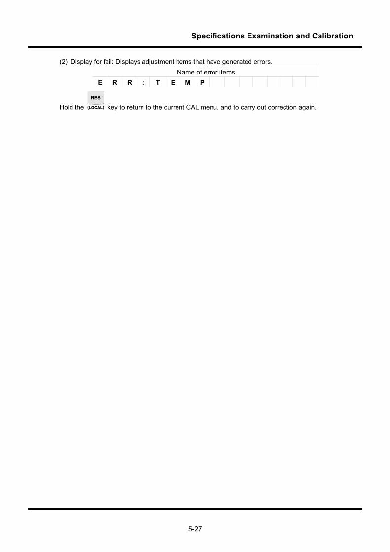
Specifications Examination and Calibration
5-27
(2) Display for fail: Displays adjustment items that have generated errors. Name of error items
E R R : T E M P
Hold the key to return to the current CAL menu, and to carry out correction again.

Specifications Examination and Calibration
5-28
5.2.10 Frequency measurement (Hz)
Carries out adjustment of the frequency measurement circuit. Specification
Sample rate SLOW 999.797 Hz – 1.00022 kHz Adjustment procedure
1. After selecting [CAL:FREQ 1.0kHz], input the 5V rms sine wave at the displayed frequency between the V・Ω・ ・°C・Hz HI-LO terminals.
2. Hold the (ENTER) key to start adjustment operation. After “Freq ... Calibrate...Verify” are displayed, a display of whether this could be carried out within
specifications is shown with SUCCESS (Success) or ERR (Fail). Menu display:
Name of adjustment items Input voltage Input frequency C A L : F R E Q 5 V & 1 k H z
(1) Display for success: S U C C E S S
Hold the (ENTER) key to move to the next CAL menu. (2) Display for fail: Displays adjustment items that have generated errors.
Name of error items C A L : F R E Q 5 V & 1 k H z
Hold the key to return to the current CAL menu, and to carry out correction again.
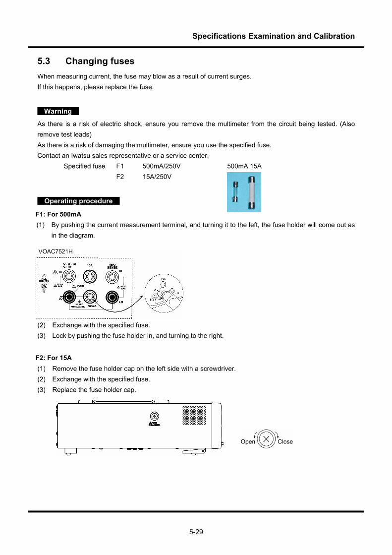
Specifications Examination and Calibration
5-29
5.3 Changing fuses When measuring current, the fuse may blow as a result of current surges. If this happens, please replace the fuse.
Warning
As there is a risk of electric shock, ensure you remove the multimeter from the circuit being tested. (Also remove test leads) As there is a risk of damaging the multimeter, ensure you use the specified fuse. Contact an Iwatsu sales representative or a service center.
Specified fuse F1 500mA/250V 500mA 15A F2 15A/250V
Operating procedure
F1: For 500mA (1) By pushing the current measurement terminal, and turning it to the left, the fuse holder will come out as
in the diagram.
(2) Exchange with the specified fuse. (3) Lock by pushing the fuse holder in, and turning to the right.
F2: For 15A (1) Remove the fuse holder cap on the left side with a screwdriver. (2) Exchange with the specified fuse. (3) Replace the fuse holder cap.
VOAC7521H

Specifications Examination and Calibration
5-30
Memo
Specifications
1234567
Chapter 6 Specifications
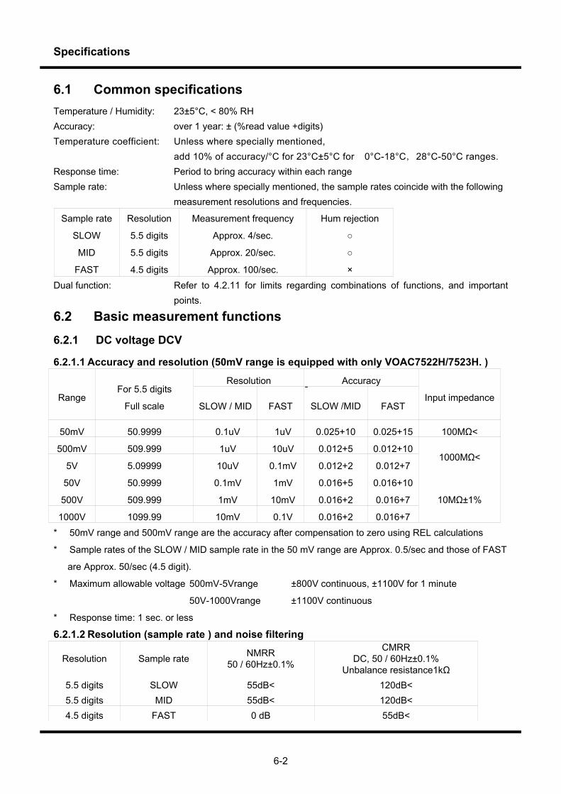
Specifications
6-2
6.1 Common specifications Temperature / Humidity: 23±5°C, < 80% RH Accuracy: over 1 year: ± (%read value +digits) Temperature coefficient: Unless where specially mentioned,
add 10% of accuracy/°C for 23°C±5°C for 0°C-18°C,28°C-50°C ranges. Response time: Period to bring accuracy within each range Sample rate: Unless where specially mentioned, the sample rates coincide with the following
measurement resolutions and frequencies.
Sample rate Resolution Measurement frequency Hum rejection
SLOW 5.5 digits Approx. 4/sec.
MID 5.5 digits Approx. 20/sec.
FAST 4.5 digits Approx. 100/sec. × Dual function: Refer to 4.2.11 for limits regarding combinations of functions, and important
points.
6.2 Basic measurement functions
6.2.1 DC voltage DCV
6.2.1.1 Accuracy and resolution (50mV range is equipped with only VOAC7522H/7523H. )
Resolution Accuracy
Range For 5.5 digits
Full scale SLOW / MID FAST SLOW /MID FAST Input impedance
50mV 50.9999 0.1uV 1uV 0.025+10 0.025+15 100MΩ<
500mV 509.999 1uV 10uV 0.012+5 0.012+10
5V 5.09999 10uV 0.1mV 0.012+2 0.012+7 1000MΩ<
50V 50.9999 0.1mV 1mV 0.016+5 0.016+10
500V 509.999 1mV 10mV 0.016+2 0.016+7
1000V 1099.99 10mV 0.1V 0.016+2 0.016+7
10MΩ±1%
* 50mV range and 500mV range are the accuracy after compensation to zero using REL calculations
* Sample rates of the SLOW / MID sample rate in the 50 mV range are Approx. 0.5/sec and those of FAST
are Approx. 50/sec (4.5 digit).
* Maximum allowable voltage 500mV-5Vrange ±800V continuous, ±1100V for 1 minute
50V-1000Vrange ±1100V continuous
* Response time: 1 sec. or less
6.2.1.2 Resolution (sample rate ) and noise filtering
Resolution Sample rate NMRR 50 / 60Hz±0.1%
CMRR DC, 50 / 60Hz±0.1%
Unbalance resistance1kΩ 5.5 digits SLOW 55dB< 120dB< 5.5 digits MID 55dB< 120dB< 4.5 digits FAST 0 dB 55dB<

Specifications
6-3
6.2.2 DC voltage CH-B DCV (equipped with only VOAC7520H/7523H)
6.2.2.1 Accuracy and resolution
Accuracy Range Full scale Resolution
SLOW/MID FAST Input impedance
5V 5.0999 0.1mV 0.025+2 0.025+30
50V 50.999 1mV 0.025+2 0.025+8
300V 309.99 10mV 0.025+2 0.025+ 5
CH-B:H-CH-B:L 10MΩ±3%
CH-B:H-CH-A:L 5MΩ±3%
CH-B:L-CH-A:L 5MΩ±3% Note:
1. Maximum allowable voltage: ±300V continuous between CH-B HI-LO, and ±300V continuous between CH-A LO-CH-B HI or LO
2. Response time: within 1 second
6.2.2.2 Resolution (sample rate) and noise suppression
Resolution Sample rate NMRR 50/60Hz±0.1%
CMRR DC,50/60Hz±0.1%
Unbalance resistance 1kΩ
Voltage effect between CH-A:L
4.5 digits SLOW/MID 55dB< 120dB< 4.5 digits FAST 0 dB 55dB<
56dB<
6.2.3 AC voltage ACV, (DC+AC)V
6.2.3.1 Resolution and measurement range True root mean square value detection Crest factor : <3
Measurement range Range Full scale Resolution SLOW(15Hz~) SLOW(200Hz~)
/MID/FAST Input impedance
500mV 509.999 1uV
5V 5.09999 10uV
50V 50.9999 0.1mV
15Hz~100kHz (~300kHz only on
VOAC7522H / 7523H)
200Hz~100kHz (~300kHz only on
VOAC7522H / 7523H)
500V 509.999 1mV 45Hz~100kHz 200Hz~100kHz
750V 759.99 10mV 45Hz~20kHz 200Hz~20kHz
Approx. <1MΩ//100pF
Sample rate Resolution Measurement
frequency Response time ※
SLOW(15Hz~) 5.5 digits 4/sec. 3 sec. or less
SLOW(200Hz~) 5.5 digits 4/sec. 2 sec. or less
MID/FAST 5.5 digits 20/sec. 2 sec. or less
※ The time that a value to be measured becomes a stable value ±100 digits in 0⇒FS(Full Scale) of the
same range
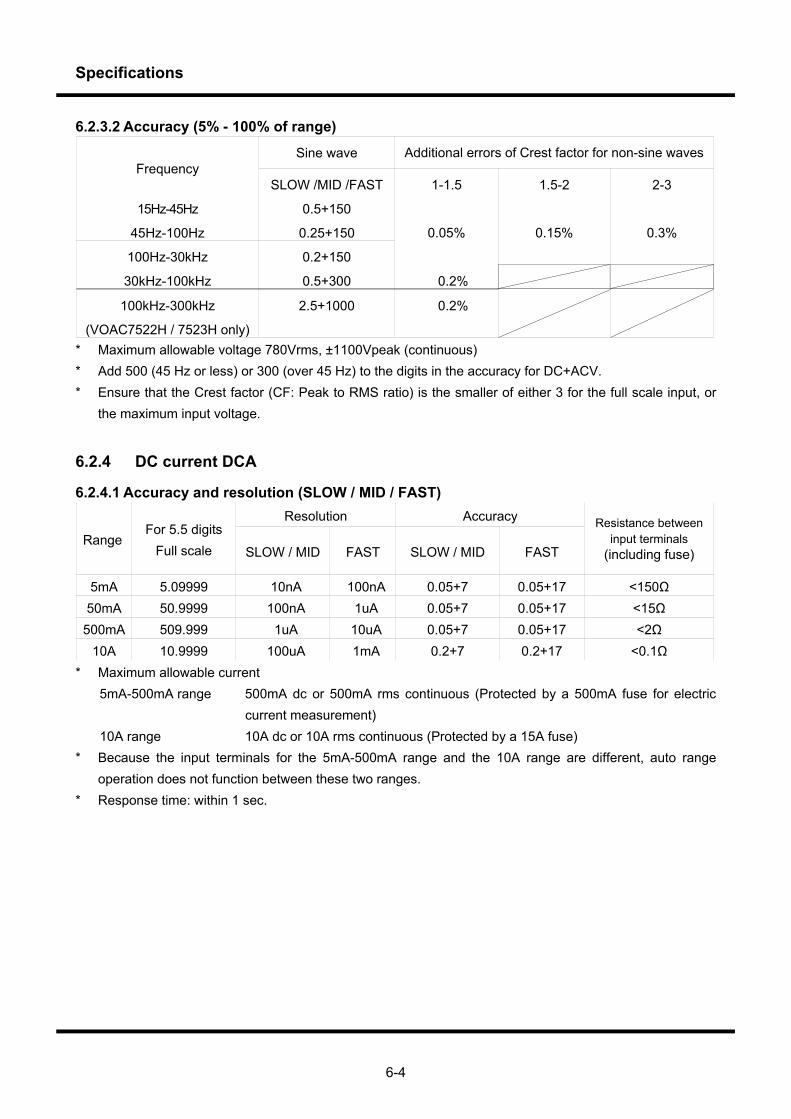
Specifications
6-4
6.2.3.2 Accuracy (5% - 100% of range)
Sine wave Additional errors of Crest factor for non-sine wavesFrequency
SLOW /MID /FAST 1-1.5 1.5-2 2-3
15Hz-45Hz 0.5+150
45Hz-100Hz 0.25+150
100Hz-30kHz 0.2+150
0.05% 0.15% 0.3%
30kHz-100kHz 0.5+300 0.2%
100kHz-300kHz
(VOAC7522H / 7523H only)
2.5+1000 0.2%
* Maximum allowable voltage 780Vrms, ±1100Vpeak (continuous) * Add 500 (45 Hz or less) or 300 (over 45 Hz) to the digits in the accuracy for DC+ACV. * Ensure that the Crest factor (CF: Peak to RMS ratio) is the smaller of either 3 for the full scale input, or
the maximum input voltage.
6.2.4 DC current DCA
6.2.4.1 Accuracy and resolution (SLOW / MID / FAST) Resolution Accuracy
Range For 5.5 digits
Full scale SLOW / MID FAST SLOW / MID FAST
Resistance between input terminals
(including fuse)
5mA 5.09999 10nA 100nA 0.05+7 0.05+17 <150Ω 50mA 50.9999 100nA 1uA 0.05+7 0.05+17 <15Ω
500mA 509.999 1uA 10uA 0.05+7 0.05+17 <2Ω 10A 10.9999 100uA 1mA 0.2+7 0.2+17 <0.1Ω
* Maximum allowable current 5mA-500mA range 500mA dc or 500mA rms continuous (Protected by a 500mA fuse for electric
current measurement) 10A range 10A dc or 10A rms continuous (Protected by a 15A fuse) * Because the input terminals for the 5mA-500mA range and the 10A range are different, auto range
operation does not function between these two ranges. * Response time: within 1 sec.
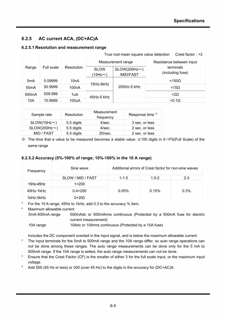
Specifications
6-5
6.2.5 AC current ACA, (DC+AC)A
6.2.5.1 Resolution and measurement range True root mean square value detection Crest factor : <3
Measurement range Range Full scale Resolution SLOW
(15Hz~) SLOW(200Hz~)
/MID/FAST
Resistance between input terminals
(including fuse)
5mA 5.09999 10nA <150Ω
50mA 50.9999 100nA 15Hz-5kHz
200Hz-5 kHz <15Ω
500mA 509.999 1uA <2Ω 10A 10.9999 100uA
45Hz-5 kHz <0.1Ω
Sample rate Resolution Measurement
frequency Response time ※
SLOW(15Hz~) 5.5 digits 4/sec. 3 sec. or less SLOW(200Hz~) 5.5 digits 4/sec. 2 sec. or less
MID / FAST 5.5 digits 20/sec. 2 sec. or less ※ The time that a value to be measured becomes a stable value ±100 digits in 0⇒FS(Full Scale) of the
same range
6.2.5.2 Accuracy (5%-100% of range; 10%-100% in the 10 A range)
Sine wave Additional errors of Crest factor for non-sine waves Frequency
SLOW / MID / FAST 1-1.5 1.5-2 2-3 15Hz-45Hz 1+200
45Hz-1kHz 0.4+200
1kHz-5kHz 5+200
0.05% 0.15% 0.3%
* For the 10 A range, 45Hz to 1kHz, add 0.3 to the accuracy % item. * Maximum allowable current 5mA-500mA range 500mAdc or 500mArms continuous (Protected by a 500mA fuse for electric
current measurement) 10A range 10Adc or 10Arms continuous (Protected by a 15A fuse) Includes the DC component overlaid in the input signal, and is below the maximum allowable current. * The input terminals for the 5mA to 500mA range and the 10A range differ, so auto range operations can
not be done among these ranges. The auto range measurements can be done only for the 5 mA to 500mA range. If the 10A range is setted, the auto range measurements can not be done.
* Ensure that the Crest Factor (CF) is the smaller of either 3 for the full scale input, or the maximum input voltage.
* Add 500 (45 Hz or less) or 300 (over 45 Hz) to the digits in the accuracy for (DC+AC)A.
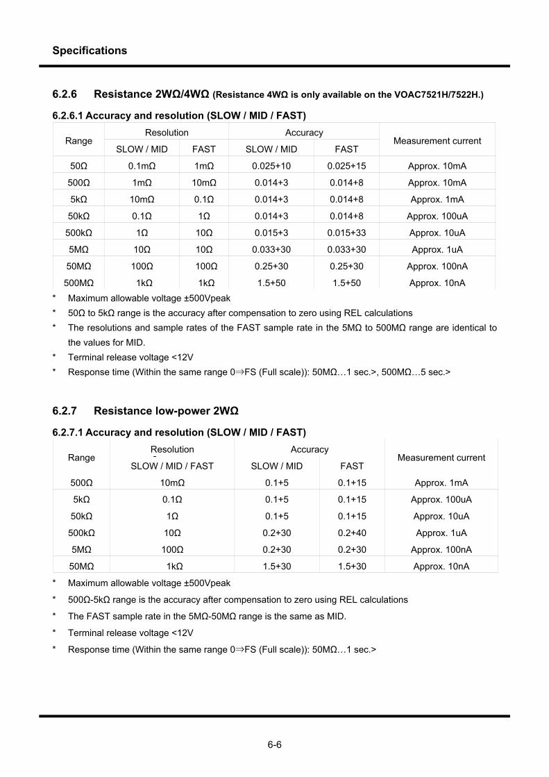
Specifications
6-6
6.2.6 Resistance 2WΩ/4WΩ (Resistance 4WΩ is only available on the VOAC7521H/7522H.)
6.2.6.1 Accuracy and resolution (SLOW / MID / FAST) Resolution Accuracy
Range SLOW / MID FAST SLOW / MID FAST
Measurement current
50Ω 0.1mΩ 1mΩ 0.025+10 0.025+15 Approx. 10mA
500Ω 1mΩ 10mΩ 0.014+3 0.014+8 Approx. 10mA
5kΩ 10mΩ 0.1Ω 0.014+3 0.014+8 Approx. 1mA
50kΩ 0.1Ω 1Ω 0.014+3 0.014+8 Approx. 100uA
500kΩ 1Ω 10Ω 0.015+3 0.015+33 Approx. 10uA
5MΩ 10Ω 10Ω 0.033+30 0.033+30 Approx. 1uA
50MΩ 100Ω 100Ω 0.25+30 0.25+30 Approx. 100nA
500MΩ 1kΩ 1kΩ 1.5+50 1.5+50 Approx. 10nA * Maximum allowable voltage ±500Vpeak * 50Ω to 5kΩ range is the accuracy after compensation to zero using REL calculations * The resolutions and sample rates of the FAST sample rate in the 5MΩ to 500MΩ range are identical to
the values for MID. * Terminal release voltage <12V * Response time (Within the same range 0⇒FS (Full scale)): 50MΩ…1 sec.>, 500MΩ…5 sec.>
6.2.7 Resistance low-power 2WΩ
6.2.7.1 Accuracy and resolution (SLOW / MID / FAST) Resolution Accuracy
Range SLOW / MID / FAST SLOW / MID FAST
Measurement current
500Ω 10mΩ 0.1+5 0.1+15 Approx. 1mA
5kΩ 0.1Ω 0.1+5 0.1+15 Approx. 100uA
50kΩ 1Ω 0.1+5 0.1+15 Approx. 10uA
500kΩ 10Ω 0.2+30 0.2+40 Approx. 1uA
5MΩ 100Ω 0.2+30 0.2+30 Approx. 100nA
50MΩ 1kΩ 1.5+30 1.5+30 Approx. 10nA
* Maximum allowable voltage ±500Vpeak
* 500Ω-5kΩ range is the accuracy after compensation to zero using REL calculations
* The FAST sample rate in the 5MΩ-50MΩ range is the same as MID.
* Terminal release voltage <12V
* Response time (Within the same range 0⇒FS (Full scale)): 50MΩ…1 sec.>
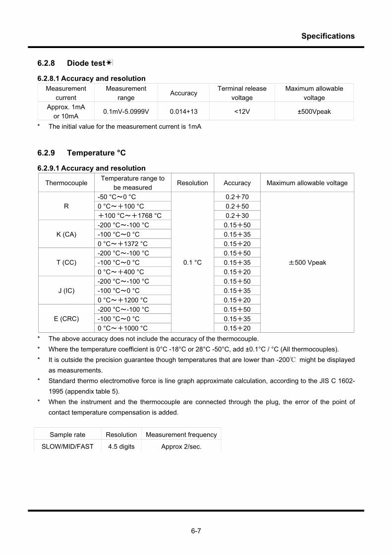
Specifications
6-7
6.2.8 Diode test
6.2.8.1 Accuracy and resolution Measurement
current Measurement
range Accuracy
Terminal release voltage
Maximum allowable voltage
Approx. 1mA or 10mA
0.1mV-5.0999V 0.014+13 <12V ±500Vpeak
* The initial value for the measurement current is 1mA
6.2.9 Temperature °C
6.2.9.1 Accuracy and resolution
Thermocouple Temperature range to
be measured Resolution Accuracy Maximum allowable voltage
-50 °C~0 °C 0.2+70 0 °C~+100 °C 0.2+50 R +100 °C~+1768 °C 0.2+30 -200 °C~-100 °C 0.15+50 -100 °C~0 °C 0.15+35 K (CA) 0 °C~+1372 °C 0.15+20 -200 °C~-100 °C 0.15+50 -100 °C~0 °C 0.15+35 T (CC) 0 °C~+400 °C 0.15+20 -200 °C~-100 °C 0.15+50 -100 °C~0 °C 0.15+35 J (IC) 0 °C~+1200 °C 0.15+20 -200 °C~-100 °C 0.15+50 -100 °C~0 °C 0.15+35 E (CRC) 0 °C~+1000 °C
0.1 °C
0.15+20
±500 Vpeak
* The above accuracy does not include the accuracy of the thermocouple. * Where the temperature coefficient is 0°C -18°C or 28°C -50°C, add ±0.1°C / °C (All thermocouples). * It is outside the precision guarantee though temperatures that are lower than -200 might be displayed
as measurements. * Standard thermo electromotive force is line graph approximate calculation, according to the JIS C 1602-
1995 (appendix table 5). * When the instrument and the thermocouple are connected through the plug, the error of the point of
contact temperature compensation is added.
Sample rate Resolution Measurement frequency
SLOW/MID/FAST 4.5 digits Approx 2/sec.

Specifications
6-8
6.2.10 Frequency measurement FREQ
6.2.10.1 Accuracy and display digit numbers AC Coupling, reciprocal process, crest factor <3
Sample rate Measurement frequency
(gate interval) Displayed digits and measurement range Accuracy
SLOW Approx 0.5/s (1s) 6 digits 15.0000Hz-1.00000MHz
0.02+2 MID 4/s (100ms) 5 digits 15.000Hz-1.0000 MHz
FAST 10/s (10ms) 4 digits 150.00Hz-1.000 MHz * Maximum allowable voltage 780V rms, ±1100Vpeak (continuous) * Use ACV AUTO range for the input attenuator (500mV-750V) * Input range 15Hz-100kHz: 100mV-750V 100kHz-500kHz: 200mV-2.2×10⁷[V・Hz] 500kHz-1MHz: 500mV-2.2×10⁷[V・Hz] For input of 200V rms or more, ensure at least 100kHz. (According to ACV specifications) * Less than 15Hz and more than 1MHz may be displayed, however this is outside guarantees of accuracy.
6.3 General functions Display 5×7 dot, 16 digits, fluorescent display tube Auto range: “509999” or more, range up, “045000” or under, range down. Over display: “±⊔⊔⊔⊔⊔⊔” Method of operation drift compensated triple integrated Polarity display For negative polarity, display “-” Withstand voltage ±500V DC (external ground and all input terminals) Power supply AC100V, 110V, 220V, 240V±10% 50/60Hz Other than AC100V is a factory option. Power consumption <21VA (including options) Over Voltage Category II Warm up time The multimeter’s specifications are guaranteed after at least one hour of warm
up after the power has been turned on.
6.4 Common functions Measurement period switching, (free run / interval, and hold / single / n sample), manual range / auto range, (excepting some current ranges), statistical calculations (MAX / MIN / X / σ), running average calculations (AVG), scaling calculations ((X-A) *B / C), D/X), relative calculations, (REL), compare calculations (Hi / Go / Lo), panel set up memory, time (elapsed time), stamped data memory, low power mode (turning off VFD)
6.5 Optional interface (Refer to section 7.1 or Remote Manual for details.) RS-232 Standard equipment Ethernet (10BASE-T) Option SC-351 (Can be mounted in SLOT A by users) DIO (Ext-Trig, Comp-Out) Option SC-352 (Can be mounted in SLOT B by users) GP-IB (IEEE-488.2) Option SC-353 (Can be mounted in SLOT A by users) D/A converter Option SC-354 (Can be mounted in SLOT B by users)
Specifications
6-9
6.6 Optional accessories (Refer to section 7.4 for details.) SC-004 Shield cable for high resistance at 100MΩ or lower SC-0107 Sheath-type thermocouple (Type-K) SC-0116 Thermocouple (Type-K) SC-020 Backup leads for standard accompanying test leads (1000V,10A CE compatible product) SC-023 Alligator clips (600V, 10A CE compatible product) especially for SC-020 SC-026 Arrow-shaped clips (AC30V / DC1000V, 3A) especially for SC-020 SC-028 DC180A, AC130A, Current clamp probe SC-525 USB to RS Converter Instruction manual (CD) User’s guide (Printed matter)
6.7 Environmental conditions Operating temperature 0°C-50°C (≦80%RH). However, there is to be no condensation, and in the 40- and humidity range 50°C range, 70% or less RH. Storage temperature -20°C~0°C, 40°C~60°C, (≦70%RH). However, there is to be no condensation. and humidity range 0°C~40°C, (≦70%RH). However, there is to be no condensation. Pollution Degree 2
6.8 Accessories Fuses for current measurement 2 pieces for each (500mA, 15A) (Different to those contained in the multimeter) Test lead 1 couple Screwdriver for adjustment 1 Power code 1 Code strap 1 Instruction manual (CD) 1 User’s Guide 1 Clear file 1
6.9 Expected operating life Fluorescent display tube Reduction in brightness by half, in approx 30,000 hours Relay Approx. 10,000,000 times (when using the optimum range) Approx. 100,000 times (when using over loaded range) (Remarks) Since these parts are articles of consumption, you need to pay the
cost for repair and exchange.
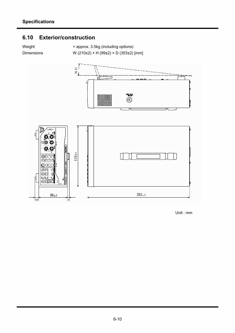
Specifications
6-10
6.10 Exterior/construction Weight < approx. 3.5kg (including options) Dimensions W (210±2) × H (99±2) × D (353±2) [mm]
Unit : mm
Options and Accessories
1234567
Chapter 7 Options and Accessories

Options and Accessories
7-2
7.1 Options Available options include Ethernet units (SC-351), Digital I/O units (SC-352), GP-IB units (SC-353), and D / A converter units (SC-354).
7.1.1 Connection
Rear panel
1 AC LINE INPUT Inlet for connecting power cord 2 RS-232 connector 3 OPTION SLOT A Slot for SC-353 GPIB unit or SC-351 Ethernet unit 4 OPTION SLOT B Slot for SC-352 digital I/O unit (Ext-Trig Comp-Out) or SC-354 D / A converter unit Please refer to " 7.2.2 Attaching and removing option units" for the method of installing the
option unit.
7.1.2 Operation
Remote control is an option with this multi meter, through the use of GP-IB, RS-232, or Ethernet interfaces. Configuration of the types of communication is carried out through the RS, IP and GPIB menus in the SYSTEM menu. For details of commands, refer to the “Remote Section.”
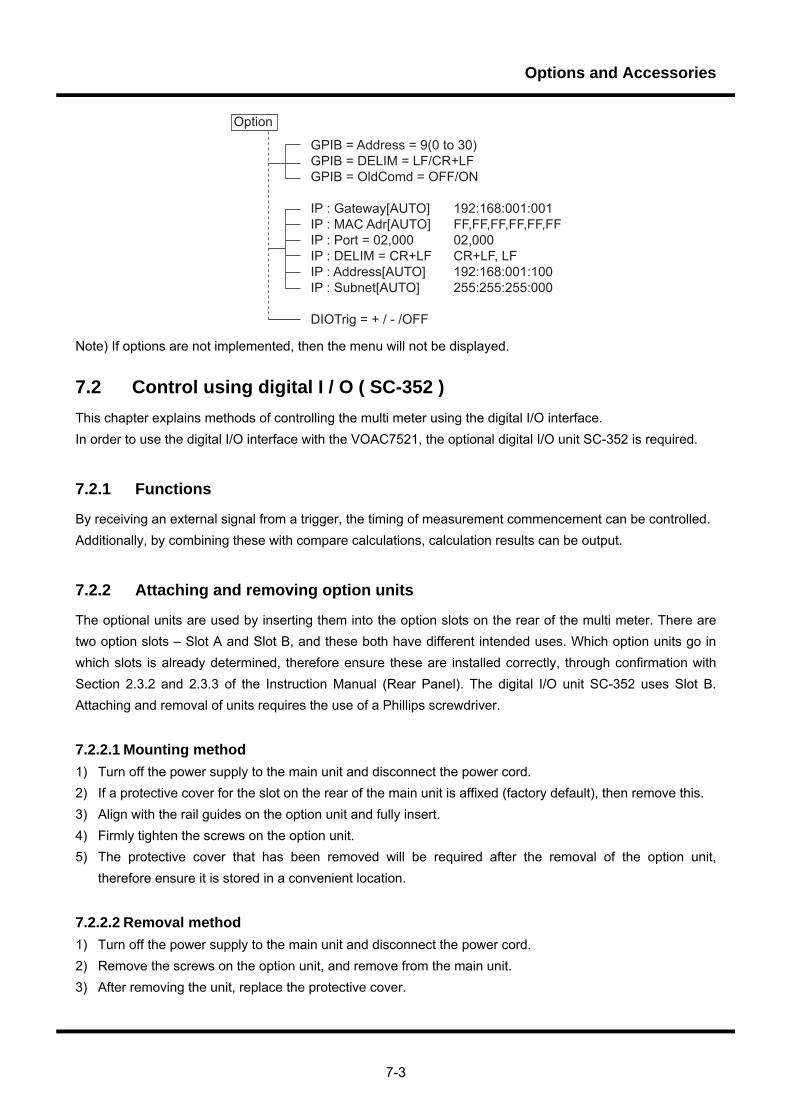
Options and Accessories
7-3
GPIB = Address = 9(0 to 30)GPIB = DELIM = LF/CR+LFGPIB = OldComd = OFF/ON
IP : Gateway[AUTO] 192:168:001:001IP : MAC Adr[AUTO] FF,FF,FF,FF,FF,FFIP : Port = 02,000 02,000IP : DELIM = CR+LF CR+LF, LFIP : Address[AUTO] 192:168:001:100IP : Subnet[AUTO] 255:255:255:000
DIOTrig = + / - /OFF
Option
Note) If options are not implemented, then the menu will not be displayed. 7.2 Control using digital I / O ( SC-352 ) This chapter explains methods of controlling the multi meter using the digital I/O interface. In order to use the digital I/O interface with the VOAC7521, the optional digital I/O unit SC-352 is required.
7.2.1 Functions
By receiving an external signal from a trigger, the timing of measurement commencement can be controlled. Additionally, by combining these with compare calculations, calculation results can be output.
7.2.2 Attaching and removing option units
The optional units are used by inserting them into the option slots on the rear of the multi meter. There are two option slots – Slot A and Slot B, and these both have different intended uses. Which option units go in which slots is already determined, therefore ensure these are installed correctly, through confirmation with Section 2.3.2 and 2.3.3 of the Instruction Manual (Rear Panel). The digital I/O unit SC-352 uses Slot B. Attaching and removal of units requires the use of a Phillips screwdriver.
7.2.2.1 Mounting method 1) Turn off the power supply to the main unit and disconnect the power cord. 2) If a protective cover for the slot on the rear of the main unit is affixed (factory default), then remove this. 3) Align with the rail guides on the option unit and fully insert. 4) Firmly tighten the screws on the option unit. 5) The protective cover that has been removed will be required after the removal of the option unit,
therefore ensure it is stored in a convenient location.
7.2.2.2 Removal method 1) Turn off the power supply to the main unit and disconnect the power cord. 2) Remove the screws on the option unit, and remove from the main unit. 3) After removing the unit, replace the protective cover.
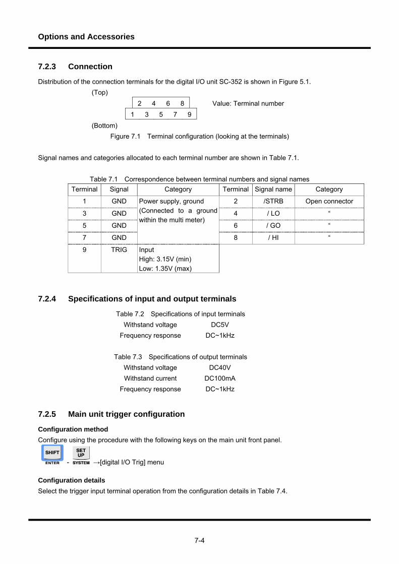
Options and Accessories
7-4
7.2.3 Connection
Distribution of the connection terminals for the digital I/O unit SC-352 is shown in Figure 5.1. (Top)
2 4 6 8 Value: Terminal number 1 3 5 7 9
(Bottom) Figure 7.1 Terminal configuration (looking at the terminals)
Signal names and categories allocated to each terminal number are shown in Table 7.1.
Table 7.1 Correspondence between terminal numbers and signal names Terminal Signal Category Terminal Signal name Category
1 GND 2 /STRB Open connector
3 GND 4 / LO “
5 GND 6 / GO “
7 GND
Power supply, ground (Connected to a ground within the multi meter)
8 / HI “
9 TRIG Input High: 3.15V (min) Low: 1.35V (max)
7.2.4 Specifications of input and output terminals
Table 7.2 Specifications of input terminals Withstand voltage DC5V
Frequency response DC~1kHz
Table 7.3 Specifications of output terminals Withstand voltage DC40V Withstand current DC100mA
Frequency response DC~1kHz
7.2.5 Main unit trigger configuration
Configuration method Configure using the procedure with the following keys on the main unit front panel.
- →[digital I/O Trig] menu Configuration details Select the trigger input terminal operation from the configuration details in Table 7.4.
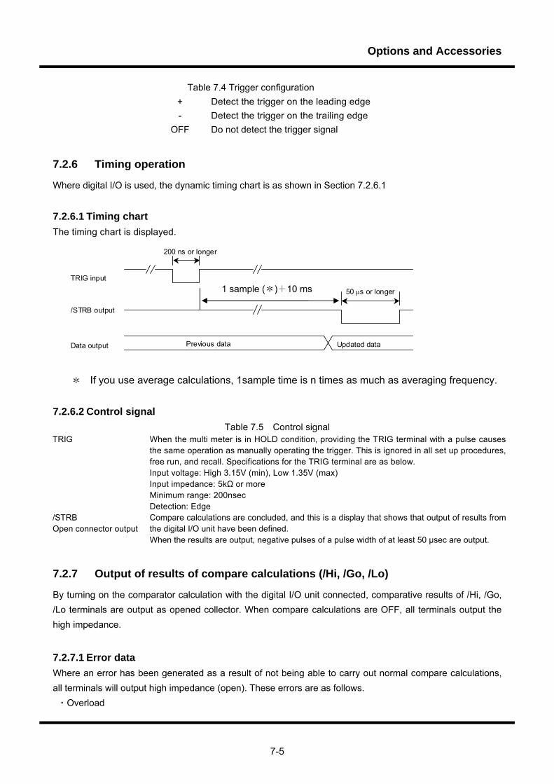
Options and Accessories
7-5
Table 7.4 Trigger configuration + Detect the trigger on the leading edge - Detect the trigger on the trailing edge
OFF Do not detect the trigger signal
7.2.6 Timing operation
Where digital I/O is used, the dynamic timing chart is as shown in Section 7.2.6.1
7.2.6.1 Timing chart The timing chart is displayed.
旧データ Updated data
TRIG input
/STRB output
200 ns or longer
50 μs or longer
Previous data Data output
* If you use average calculations, 1sample time is n times as much as averaging frequency.
7.2.6.2 Control signal Table 7.5 Control signal
TRIG When the multi meter is in HOLD condition, providing the TRIG terminal with a pulse causes the same operation as manually operating the trigger. This is ignored in all set up procedures, free run, and recall. Specifications for the TRIG terminal are as below. Input voltage: High 3.15V (min), Low 1.35V (max) Input impedance: 5kΩ or more Minimum range: 200nsec Detection: Edge
/STRB Open connector output
Compare calculations are concluded, and this is a display that shows that output of results from the digital I/O unit have been defined. When the results are output, negative pulses of a pulse width of at least 50 μsec are output.
7.2.7 Output of results of compare calculations (/Hi, /Go, /Lo)
By turning on the comparator calculation with the digital I/O unit connected, comparative results of /Hi, /Go, /Lo terminals are output as opened collector. When compare calculations are OFF, all terminals output the high impedance.
7.2.7.1 Error data Where an error has been generated as a result of not being able to carry out normal compare calculations, all terminals will output high impedance (open). These errors are as follows. ・Overload
1 sample (*)+10 ms
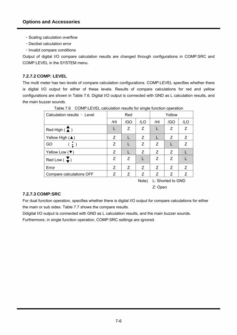
Options and Accessories
7-6
・Scaling calculation overflow ・Decibel calculation error ・Invalid compare conditions Output of digital I/O compare calculation results are changed through configurations in COMP:SRC and COMP:LEVEL in the SYSTEM menu.
7.2.7.2 COMP: LEVEL The multi meter has two levels of compare calculation configurations. COMP:LEVEL specifies whether there is digital I/O output for either of these levels. Results of compare calculations for red and yellow configurations are shown in Table 7.6. Digital I/O output is connected with GND as L calculation results, and the main buzzer sounds.
Table 7.6 COMP:LEVEL calculation results for single function operation Red Yellow Calculation results ∖ Level
/HI /GO /LO /HI /GO /LO
Red High ( ) L Z Z L Z Z
Yellow High () Z L Z L Z Z GO ( ) Z L Z Z L Z
Yellow Low () Z L Z Z Z L
Red Low ( ) Z Z L Z Z L
Error Z Z Z Z Z Z Compare calculations OFF Z Z Z Z Z Z
Note) L: Shorted to GND Z: Open
7.2.7.3 COMP:SRC For dual function operation, specifies whether there is digital I/O output for compare calculations for either the main or sub sides. Table 7.7 shows the compare results. Ddigital I/O output is connected with GND as L calculation results, and the main buzzer sounds. Furthermore, in single function operation, COMP:SRC settings are ignored.
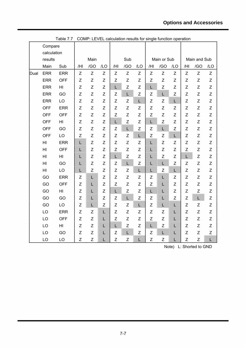
Options and Accessories
7-7
Table 7.7 COMP: LEVEL calculation results for single function operation
Compare calculation results Main Sub Main or Sub Main and Sub
Main Sub /HI /GO /LO /HI /GO /LO /HI /GO /LO /HI /GO /LO
Dual ERR ERR Z Z Z Z Z Z Z Z Z Z Z Z
ERR OFF Z Z Z Z Z Z Z Z Z Z Z Z
ERR HI Z Z Z L Z Z L Z Z Z Z Z
ERR GO Z Z Z Z L Z Z L Z Z Z Z
ERR LO Z Z Z Z Z L Z Z L Z Z Z
OFF ERR Z Z Z Z Z Z Z Z Z Z Z Z
OFF OFF Z Z Z Z Z Z Z Z Z Z Z Z
OFF HI Z Z Z L Z Z L Z Z Z Z Z
OFF GO Z Z Z Z L Z Z L Z Z Z Z
OFF LO Z Z Z Z Z L Z Z L Z Z Z
HI ERR L Z Z Z Z Z L Z Z Z Z Z
HI OFF L Z Z Z Z Z L Z Z Z Z Z
HI HI L Z Z L Z Z L Z Z L Z Z
HI GO L Z Z Z L Z L L Z Z Z Z
HI LO L Z Z Z Z L L Z L Z Z Z
GO ERR Z L Z Z Z Z Z L Z Z Z Z
GO OFF Z L Z Z Z Z Z L Z Z Z Z
GO HI Z L Z L Z Z L L Z Z Z Z
GO GO Z L Z Z L Z Z L Z Z L Z
GO LO Z L Z Z Z L Z L L Z Z Z
LO ERR Z Z L Z Z Z Z Z L Z Z Z
LO OFF Z Z L Z Z Z Z Z L Z Z Z
LO HI Z Z L L Z Z L Z L Z Z Z
LO GO Z Z L Z L Z Z L L Z Z Z
LO LO Z Z L Z Z L Z Z L Z Z L
Note) L: Shorted to GND
Options and Accessories
7-8
7.3 D/A converter SC-354 (Optional) This chapter will explain the overview and the operation method of D/A converter SC-354 option etc. Please refer to a remote control with the remote control manual of this manual and “5.6.16 Remote control of the D/A converter “ for the remote control and the command explanation of D/A converter SC-354. Note) This option can be used with the equipment since firmware Ver1.23.
7.3.1 Overview
The SC-354 D/A converter option for the VOAC752XH series of digital multimeters converts and outputs the
results of multimeter measurements to DC voltages. The converter can be used as an interface for inputting
multimeter measurement results to pen plotters and other analog input devices.
The converter is equipped with the following main features:
・ Input signal system and isolation
・ Analog output including polarity of BCD3 decimal data
・ Switching between three ranges to match the sensitivity of connected devices
・ Fixed output for calibration (zero, full-scale)
7.3.2 Attaching/Detaching the option unit
Utilize the option unit by inserting it into one of the option slots at the back of the main unit. The option slots
consist of slot A and slot B. Attach the D/A converter unit to slot B. It cannot be attached to slot A. You will
need a Phillips screwdriver to attach/detach the unit.
Installation method
1) Turn the main unit off and remove the power cord.
2) If there is a protective cover on the slot at the back of the main unit (factory-installed), remove it.
3) Insert the converter all the way to the back along the option unit rail guide.
4) Firmly tighten the screws on the option unit.
5) Since the protective cover that was removed will have to be replaced when the option unit is not
needed, store it in a handy location.
Removal method 1) Turn the main unit off and remove the power cord.
2) Loosen the screws on the option unit and remove them from the main unit.
3) After the converter has been removed, replace the protective cover on the main unit.
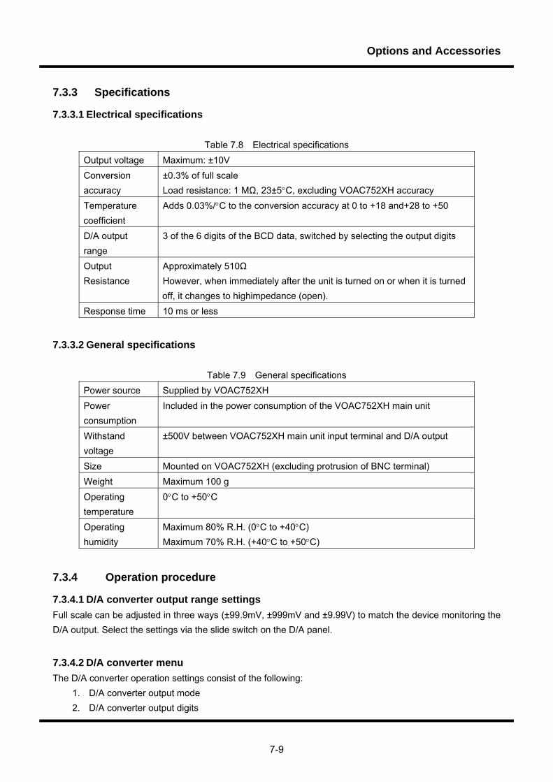
Options and Accessories
7-9
7.3.3 Specifications
7.3.3.1 Electrical specifications
Table 7.8 Electrical specifications Output voltage Maximum: ±10V Conversion accuracy
±0.3% of full scale Load resistance: 1 MΩ, 23±5°C, excluding VOAC752XH accuracy
Temperature coefficient
Adds 0.03%/°C to the conversion accuracy at 0 to +18 and+28 to +50
D/A output range
3 of the 6 digits of the BCD data, switched by selecting the output digits
Output Resistance
Approximately 510Ω However, when immediately after the unit is turned on or when it is turned off, it changes to highimpedance (open).
Response time 10 ms or less
7.3.3.2 General specifications
Table 7.9 General specifications Power source Supplied by VOAC752XH Power consumption
Included in the power consumption of the VOAC752XH main unit
Withstand voltage
±500V between VOAC752XH main unit input terminal and D/A output
Size Mounted on VOAC752XH (excluding protrusion of BNC terminal) Weight Maximum 100 g Operating temperature
0°C to +50°C
Operating humidity
Maximum 80% R.H. (0°C to +40°C) Maximum 70% R.H. (+40°C to +50°C)
7.3.4 Operation procedure
7.3.4.1 D/A converter output range settings Full scale can be adjusted in three ways (±99.9mV, ±999mV and ±9.99V) to match the device monitoring the D/A output. Select the settings via the slide switch on the D/A panel.
7.3.4.2 D/A converter menu The D/A converter operation settings consist of the following:
1. D/A converter output mode 2. D/A converter output digits
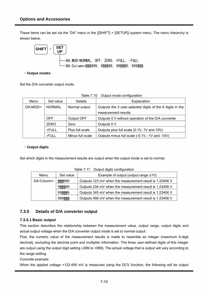
Options and Accessories
7-10
These items can be set via the “DA” menu in the ([SHIFT] + [SETUP]) system menu. The menu hierarchy is shown below.
SHIFT SETUP
DA:MOD=NORMAL, OFF, ZERO, +FULL, -FULL
DA:Column=999999, 999999, 999999, 999999
+
・Output modes
Set the D/A converter output mode.
Table 7.10 Output mode configuration Menu Set value Details Explanation
NORMAL Normal output Outputs the 3 user-selected digits of the 6 digits in the measurement results
OFF Output OFF Outputs 0 V without operation of the D/A converter ZERO Zero Outputs 0 V +FULL Plus full scale Outputs plus full scale (0.1V, 1V and 10V)
:DA:MOD=
-FULL Minus full scale Outputs minus full scale (-0.1V, -1V and -10V)
・Output digits Set which digits in the measurement results are output when the output mode is set to normal.
Table 7.11 Output digits configuration Menu Set value Example of output (output range ±1V)
999999 Outputs 123 mV when the measurement result is 1.23456 V 999999 Outputs 234 mV when the measurement result is 1.23456 V 999999 Outputs 345 mV when the measurement result is 1.23456 V
:DA:Column=
999999 Outputs 456 mV when the measurement result is 1.23456 V
7.3.5 Details of D/A converter output
7.3.5.1 Basic output This section describes the relationship between the measurement value, output range, output digits and actual output voltage when the D/A converter output mode is set to normal output. First, the numeric value of the measurement results is made to resemble an integer (maximum 6-digit decimal), excluding the decimal point and multiplier information. The three user-defined digits of this integer are output using the output digit setting (-999 to +999). The actual voltage that is output will vary according to the range setting. Concrete example: When the applied voltage +123.456 mV is measured uisng the DCV function, the following will be output
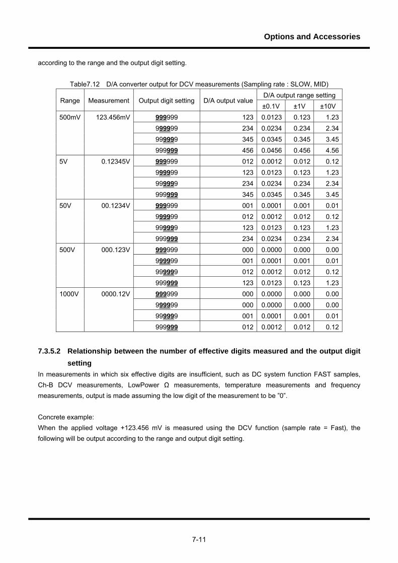
Options and Accessories
7-11
according to the range and the output digit setting.
Table7.12 D/A converter output for DCV measurements (Sampling rate : SLOW, MID) D/A output range setting
Range Measurement Output digit setting D/A output value±0.1V ±1V ±10V
999999 123 0.0123 0.123 1.23999999 234 0.0234 0.234 2.34999999 345 0.0345 0.345 3.45
500mV 123.456mV
999999 456 0.0456 0.456 4.56999999 012 0.0012 0.012 0.12999999 123 0.0123 0.123 1.23999999 234 0.0234 0.234 2.34
5V 0.12345V
999999 345 0.0345 0.345 3.45999999 001 0.0001 0.001 0.01999999 012 0.0012 0.012 0.12999999 123 0.0123 0.123 1.23
50V 00.1234V
999999 234 0.0234 0.234 2.34999999 000 0.0000 0.000 0.00999999 001 0.0001 0.001 0.01999999 012 0.0012 0.012 0.12
500V 000.123V
999999 123 0.0123 0.123 1.23999999 000 0.0000 0.000 0.00999999 000 0.0000 0.000 0.00999999 001 0.0001 0.001 0.01
1000V 0000.12V
999999 012 0.0012 0.012 0.12
7.3.5.2 Relationship between the number of effective digits measured and the output digit setting
In measurements in which six effective digits are insufficient, such as DC system function FAST samples, Ch-B DCV measurements, LowPower Ω measurements, temperature measurements and frequency measurements, output is made assuming the low digit of the measurement to be ”0”. Concrete example: When the applied voltage +123.456 mV is measured using the DCV function (sample rate = Fast), the following will be output according to the range and output digit setting.
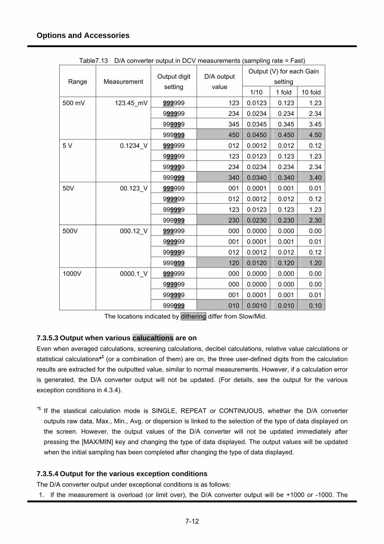
Options and Accessories
7-12
Table7.13 D/A converter output in DCV measurements (sampling rate = Fast) Output (V) for each Gain
setting Range Measurement Output digit
setting D/A output
value 1/10 1 fold 10 fold
999999 123 0.0123 0.123 1.23999999 234 0.0234 0.234 2.34999999 345 0.0345 0.345 3.45
500 mV 123.45_mV
999999 450 0.0450 0.450 4.50999999 012 0.0012 0.012 0.12999999 123 0.0123 0.123 1.23999999 234 0.0234 0.234 2.34
5 V 0.1234_V
999999 340 0.0340 0.340 3.40999999 001 0.0001 0.001 0.01999999 012 0.0012 0.012 0.12999999 123 0.0123 0.123 1.23
50V 00.123_V
999999 230 0.0230 0.230 2.30999999 000 0.0000 0.000 0.00999999 001 0.0001 0.001 0.01999999 012 0.0012 0.012 0.12
500V 000.12_V
999999 120 0.0120 0.120 1.20999999 000 0.0000 0.000 0.00999999 000 0.0000 0.000 0.00999999 001 0.0001 0.001 0.01
1000V 0000.1_V
999999 010 0.0010 0.010 0.10The locations indicated by dithering differ from Slow/Mid.
7.3.5.3 Output when various calucaltions are on Even when averaged calculations, screening calculations, decibel calculations, relative value calculations or statistical calculations*1 (or a combination of them) are on, the three user-defined digits from the calculation results are extracted for the outputted value, similar to normal measurements. However, if a calculation error is generated, the D/A converter output will not be updated. (For details, see the output for the various exception conditions in 4.3.4).
*1 If the stastical calculation mode is SINGLE, REPEAT or CONTINUOUS, whether the D/A converter
outputs raw data, Max., Min., Avg. or dispersion is linked to the selection of the type of data displayed on the screen. However, the output values of the D/A converter will not be updated immediately after pressing the [MAX/MIN] key and changing the type of data displayed. The output values will be updated when the initial sampling has been completed after changing the type of data displayed.
7.3.5.4 Output for the various exception conditions The D/A converter output under exceptional conditions is as follows: 1. If the measurement is overload (or limit over), the D/A converter output will be +1000 or -1000. The
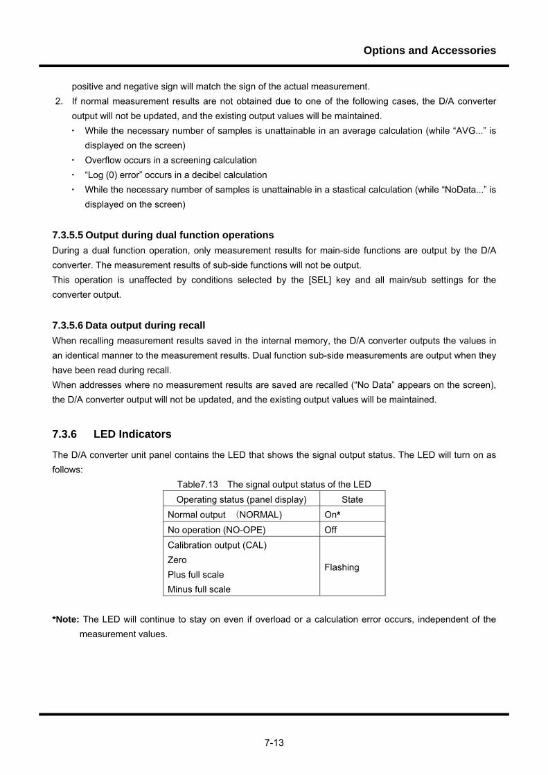
Options and Accessories
7-13
positive and negative sign will match the sign of the actual measurement. 2. If normal measurement results are not obtained due to one of the following cases, the D/A converter
output will not be updated, and the existing output values will be maintained. ・ While the necessary number of samples is unattainable in an average calculation (while “AVG...” is
displayed on the screen) ・ Overflow occurs in a screening calculation ・ “Log (0) error” occurs in a decibel calculation ・ While the necessary number of samples is unattainable in a stastical calculation (while “NoData...” is
displayed on the screen)
7.3.5.5 Output during dual function operations During a dual function operation, only measurement results for main-side functions are output by the D/A converter. The measurement results of sub-side functions will not be output. This operation is unaffected by conditions selected by the [SEL] key and all main/sub settings for the converter output.
7.3.5.6 Data output during recall When recalling measurement results saved in the internal memory, the D/A converter outputs the values in an identical manner to the measurement results. Dual function sub-side measurements are output when they have been read during recall. When addresses where no measurement results are saved are recalled (“No Data” appears on the screen), the D/A converter output will not be updated, and the existing output values will be maintained.
7.3.6 LED Indicators
The D/A converter unit panel contains the LED that shows the signal output status. The LED will turn on as follows:
Table7.13 The signal output status of the LED Operating status (panel display) State
Normal output (NORMAL) On* No operation (NO-OPE) Off Calibration output (CAL) Zero Plus full scale Minus full scale
Flashing
*Note: The LED will continue to stay on even if overload or a calculation error occurs, independent of the
measurement values.
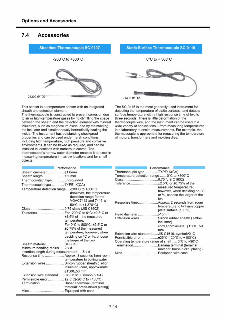
Options and Accessories
7-14
7.4 Accessories
This sensor is a temperature sensor with an integrated sheath and detection element. The thermocouple is constructed to prevent corrosion due to air or high-temperature gases by rigidly filling the space between the sheath and the detection element with mineral insulators, such as magnesium oxide, and by maintaining the insulator and simultaneously hermetically sealing the inside. The instrument has outstanding shockproof properties and can be used under harsh conditions, including high temperature, high pressure and corrosive environments. It can be flexed as required, and can be installed in locations with numerous curves. The thermocouple’s narrow outer diameter enables it to excel in measuring temperature in narrow locations and for small objects.
Performance Sheath diameter .................. 1.6mm Sheath length ...................... 150mm Thermocontact type ............ ungrounded Thermocouple type ............. TYPE: K(CA) Temperature detection range .... -200C to +800C
(however, the temperature detection range for the VOAC7412 and 7413 is -50C to +1,370C)
Class ................................... 0.75 class (JIS C1602) Tolerance ............................ For -200C to 0C: ±2.5C or
±1.5% of the measured temperature; For 0C to 800C: ±2.5C or ±0.75% of the measured temperature; however, when deciding on C or %, choose the larger of the two
Sheath material ................... SUS316 Minimum bending radius ..... 2 x d Insertion length during measurement ... 15 x d Response time .................... Approx. 3 seconds from room
temperature to boiling water Extension wires ................... Silicon rubber sheath (Teflon
insulated) cord, approximate 1500±50 mm
Extension wire standard ...... JIS C1610, symbol VX-G Permissible error ................. ±2.5C(-20C to +100C) Termination ......................... Banana terminal (terminal
material: brass-nickel plating) Misc. .................................... Equipped with case
The SC-0116 is the most generally used instrument for detecting the temperature of static surfaces, and detects surface temperature with a high response time of two to three seconds. There is little deformation of the thermocouple wire, and the instrument can be used in a wide variety of applications – from measuring temperatures in a laboratory to onsite measurements. For example, the thermocouple is appropriate for measuring the temperature of motors, transformers and molding dies.
Performance Thermocouple type .............. TYPE: K(CA) Temperature detection range ....... 0°C to +500°C Class .................................... 0.75 (JIS C1602) Tolerance ............................. ±2.5°C or ±0.75% of the
measured temperature; however, when deciding on °C or %, choose the larger of the two
Response time ..................... Approx. 2 seconds from room temperature to t=1 mm copper plate surface (100°C)
Head diameter ..................... 15mm Extension wires ................... Silicon rubber sheath (Teflon
insulator) cord,approximate 1500 ±50 mm
Extension wire standard ...... JIS C1610, symbolVX-G Permissible error ................. ±25°C (-20°C to +100°C) Operating temperature range of shaft ...... 0°C to +90°C Termination .......................... Banana terminal (terminal
material: brass-nickel plating) Misc. .................................... Equipped with case
Sheathed Thermocouple SC-0107 Static Surface Thermocouple SC-0116
-200C to +800C 0C to + 500C
21392-94-09 21392-94-12
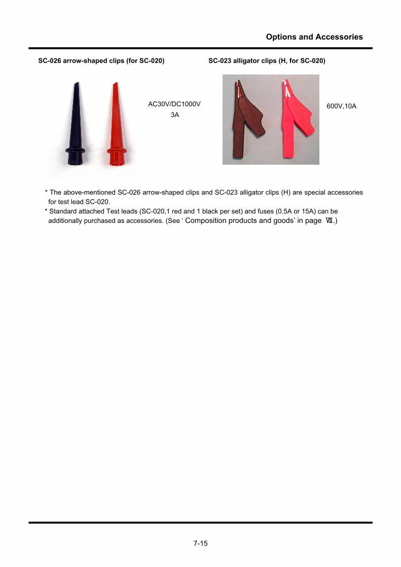
Options and Accessories
7-15
SC-026 arrow-shaped clips (for SC-020) SC-023 alligator clips (H, for SC-020)
* The above-mentioned SC-026 arrow-shaped clips and SC-023 alligator clips (H) are special accessories for test lead SC-020.
* Standard attached Test leads (SC-020,1 red and 1 black per set) and fuses (0.5A or 15A) can be additionally purchased as accessories. (See ‘ Composition products and goods’ in page Ⅶ.)
AC30V/DC1000V3A
600V,10A

Options and Accessories
7-16
USB to RS Converter SC-525 option SC-525 is a USB-Serial conversion adapter that complies with USB Specification 1.1. This adapter can be used to control measuring instruments with PCs that do not have COM ports, such as notebook PCs. SC-525 is used to connect a PC to a measuring instrument as shown in the following figure. The main specificationss are described below. For details about how to install the driver and use SC-525, see the instruction manual that comes with USB to RS Converter SC-525.
USB specification Complies with USB (Universal Serial Bus) 1.1 USB connector USB type A RS-232 connector D-SUB9P (female) Communication method Asynchronous communication RS-232 communication speed Up to 230 kbps
Power supply voltage DC 5 V (obtained from the USB bus power) Consumption current Up to 60 mA (DC 5 V) Operating temperature and humidity range 0°C to +50°C, 10% to 90% (no condensation) Storage temperature and humidity range 20°C to +65°C, 10% to 90% (no condensation) External dimensions W : 28 ± 1 mm H : 11 ± 1 mm D : 85 ± 1 mm Cable length 850 mm ± 20 mm Weight Approximately 55 g
PC
USB port
Measuring instrument
RS-232 port
Remote Control Manual

0-1
Contents
1. Remote Control .......................................................................................................1 1.1 Overview......................................................................................................................................... 1
1.2 Remote control restrictions............................................................................................................. 1
1.3 Remote/local control....................................................................................................................... 2
2. Remote Control through RS-232 Interface..............................................................3 2.1 Connecting to external devices ...................................................................................................... 3
2.2 Communication system.................................................................................................................. 4
2.3 Synchronization.............................................................................................................................. 5
2.4 Remote/local control....................................................................................................................... 5
3. Remote Control through GP-IB Interface ................................................................6 3.1 Performance................................................................................................................................... 6
3.2 Interface functions .......................................................................................................................... 6
3.3 Connections ................................................................................................................................... 7
3.4 Instrument addresses..................................................................................................................... 7
3.5 Responses to interface messages ................................................................................................. 8
3.5.1 Remote/local control .......................................................................................................... 8
3.5.2 Address commands ........................................................................................................... 9
3.5.3 Universal commands ......................................................................................................... 9
3.6 Delimiter ....................................................................................................................................... 10
3.7 I/O buffers..................................................................................................................................... 10
3.8 Manual settings required for remote operation ............................................................................ 10
4. Remote Control by Ethernet..................................................................................11 4.1 IP address settings....................................................................................................................... 11
4.2 Physical connection...................................................................................................................... 12
4.3 Network connection...................................................................................................................... 13
4.4 MAC address................................................................................................................................ 13
4.5 Communication system................................................................................................................ 14
4.6 Remote/local control..................................................................................................................... 15
4.7 Remote connection by hyper terminal.......................................................................................... 16

0-2
5. Remote Control Commands..................................................................................18 5.1 Message protocol ......................................................................................................................... 18
5.1.1 Message format ............................................................................................................... 18
5.1.2 Multi-commands............................................................................................................... 19
5.1.3 Query ............................................................................................................................... 20
5.1.4 Mnemonic......................................................................................................................... 21
5.1.5 Data formats..................................................................................................................... 21
5.2 Status report structure.................................................................................................................. 23
5.2.1 Service request (SRQ)..................................................................................................... 23
5.2.2 Status byte register .......................................................................................................... 23
5.2.3 Service request enable register ....................................................................................... 24
5.2.4 Standard event status register ......................................................................................... 24
5.2.5 Standard event status enable register ............................................................................. 25
5.2.6 Output queue ................................................................................................................... 25
5.2.7 Device-specific error occurrence event register (DDER)................................................. 25
5.2.8 Device-specific error occurrence event enable register (DDEE) ..................................... 27
5.2.9 Measurement event status register (MESR).................................................................... 28
5.2.10 Measurement event status enable register (MESE)........................................................ 29
5.3 Numeric program data.................................................................................................................. 32
5.4 Common commands .................................................................................................................... 33
5.4.1 *IDN? query (Identification).............................................................................................. 33
5.4.2 *RST commands (Reset : Initialization of the setting when the instrument
was shipped) .................................................................................................................... 34
5.4.3 *TST? query (Test : Execution of self-diagnosis) ............................................................ 35
5.4.4 *OPC command/*OPC? query (Operation Complete : Completion of device
operation) ......................................................................................................................... 36
5.4.5 *WAI commands (Wait : Execution standby of command and query) ............................. 37
5.4.6 *CLS command (Clear Status : Clearance of the standard event status register
and the device specific event register) ............................................................................ 38
5.4.7 *ESE command/*ESE? query (Event Status Enable : Setting and Retrieval) ................. 39
5.4.8 *ESR? query (Event Status Register : Retrieval and clearance)..................................... 40
5.4.9 *PSC command/*PSC? query (Power on Status Clear: Automatic clearance
when the power supply of various enable register is turned on) ..................................... 41
5.4.10 *SRE command/*SRE? query (Service Request Enable : Setting and Retrieval)........... 42
5.4.11 *STB? query (Status Byte : Retrieval) ............................................................................. 43
5.4.12 *TRG command (Trigger : Execution of measurement) .................................................. 44
5.4.13 *RCL command (Recall : Setup information)................................................................... 45
0-3
5.4.14 *SAV command (Save : Setup information)..................................................................... 46
5.5 Relationship between MAIN and SUB measurement functions................................................... 47
5.5.1 Settings related commands/queries ................................................................................ 47
5.5.2 Control-related commands/queries.................................................................................. 47
5.6 Device-specific commands........................................................................................................... 48
5.6.1 :MAIN related commands ................................................................................................ 48
5.6.1.1 :MAIN:DATA? (Retrieval of the latest measurement result) ....................................... 48
5.6.1.2 :MAIN:MEAS? (Retrieval of the measurement result corresponding to the trigger)... 49
5.6.1.3 :MAIN:FUNC/FUNC? (Setting/Retrieval of the measurement FUNCTION) ............... 50
5.6.1.4 :MAIN:RANG............................................................................................................... 51
5.6.1.4.1 :MAIN:RANG:AUTO/AUTO? (Setting/Retrieval of switching the
autorange on/off) ................................................................................................. 51
5.6.1.4.2 :MAIN:RANG:VAL/VAL? (Setting/Retrieval of the measurement range)............ 52
5.6.1.5 :MAIN:REL .................................................................................................................. 55
5.6.1.5.1 :MAIN:REL:STAT/STAT? (Switching the differential calculation on/off) ............. 55
5.6.1.5.2 :MAIN:REL:XREF/XREF? (Setting/Retrieval of the XREF parameter
of the differential calculation) .............................................................................. 56
5.6.1.5.3 :MAIN:REL:XINI (The issue of the request to initialize in the XREF
parameter of the differential calculation)............................................................. 57
5.6.1.6 :MAIN:AVG ................................................................................................................. 58
5.6.1.6.1 :MAIN:AVG:STAT/STAT? (Setting/Retrieval of switching the Moving
Average calculation on/off) ................................................................................. 58
5.6.1.6.2 :MAIN:AVG:NUMB/NUMB? (Setting/Retrieval of the number of
samples in Moving Average calculation)............................................................. 59
5.6.1.6.3 :MAIN:AVG:INIT (Initialization of the sampling results in Moving
Average calculation)............................................................................................ 60
5.6.1.7 :MAIN:CONT............................................................................................................... 61
5.6.1.7.1 :MAIN:CONT:STAT/STAT? (Setting/Retrieval of switching the
continuity test on/off) ........................................................................................... 61
5.6.1.7.2 :MAIN:CONT:RTH/RTH? (Setting/Retrieval of the thresholds in the
continuity test) ..................................................................................................... 62
5.6.1.8 :MAIN:DCBL ............................................................................................................... 63
5.6.1.8.1 :MAIN:DCBL:STAT/STAT? (Setting/Retrieval of switching the decibel
calculation on/off) ................................................................................................ 63
5.6.1.8.2 :MAIN:DCBL:MOD/MOD? (Setting/Retrieval of a dBm calculation or a
dBV calculation) .................................................................................................. 64
0-4
5.6.1.8.3 :MAIN:DCBL:RREF/RREF? (Setting/Retrieval of the standard resistance
in the dBm mode of a decibel calculation) .......................................................... 65
5.6.1.8.4 :MAIN:DCBL:VREF/VREF? (Setting/Retrieval of the standard resistance
in the dBV mode of decibel calculations) ............................................................ 66
5.6.1.9 :MAIN:COMP .............................................................................................................. 67
5.6.1.9.1 :MAIN:COMP:STAT/STAT? (Setting/Retrieval of switching the
comparator calculation on/off)............................................................................. 67
5.6.1.9.2 :MAIN:COMP:RUPP/RUPP? (Setting/Retrieval of the RED level upper
threshold value for comparator calculations) ...................................................... 68
5.6.1.9.3 :MAIN:COMP:RLOW/RLOW? (Setting/Retrieval of the RED level lower
threshold value for comparator calculations) ...................................................... 69
5.6.1.9.4 :MAIN:COMP:YUPP/YUPP? (Setting/Retrieval of the YELLOW level
upper threshold value for comparator calculations)............................................ 70
5.6.1.9.5 :MAIN:COMP:YLOW/YLOW? (Setting/Retrieval of the YELLOW level
lower threshold value for comparator calculations) ............................................ 71
5.6.1.10 :MAIN:SCAL................................................................................................................ 72
5.6.1.10.1 :MAIN:SCAL:STAT/STAT? (Setting/Retrieval of switching scaling
calculations on/off) .............................................................................................. 72
5.6.1.10.2 :MAIN:SCAL:MOD/MOD? (Setting/Retrieval of the scaling calculation
method) ............................................................................................................... 73
5.6.1.10.3 :MAIN:SCAL:VALA/VALA? (Setting/Retrieval of “A” parameter of
scaling calculations) ............................................................................................ 74
5.6.1.10.4 :MAIN:SCAL:VALB/VALB? (Setting/Retrieval of “B” parameter of
scaling calculations) ............................................................................................ 75
5.6.1.10.5 :MAIN:SCAL:VALC/VALC? (Setting/Retrieval of “C” parameter of
scaling calculations) ............................................................................................ 76
5.6.1.10.6 :MAIN:SCAL:VALD/VALD? (Setting/Retrieval of “D” parameter of
scaling calculations) ............................................................................................ 77
5.6.1.11 :MAIN:STAT................................................................................................................ 78
5.6.1.11.1 :MAIN:STAT:MOD/MOD? (Setting/Retrieval of the statistical
calculation method) ............................................................................................. 78
5.6.1.11.2 :MAIN:STAT:NUMB/NUMB? (Setting/Retrieval of the number of
samples in a statistical calculation)..................................................................... 79
5.6.1.11.3 :MAIN:STAT:INIT (Initialization of the results of statistical calculations) ........... 80 5.6.2 SUB related commands ................................................................................................... 81
5.6.3 Measurement function related commands....................................................................... 82
5.6.4 Sampling related commands ........................................................................................... 83
0-5
5.6.4.1 :SMPL:MOD/MOD? (Selection of the sampling method) ........................................... 83
5.6.4.2 :SMPL:ITVL/ITVL? (Setting/Retrieval of the interval when using free run
sampling) .................................................................................................................... 84
5.6.4.3 :SMPL:RATE/RATE? (Setting/Retrieval of the sampling rate) ................................... 85 5.6.5 Dual display related commands....................................................................................... 86
5.6.5.1 :DUAL:DATA? (The simultaneous retrieval of the latest measurement results
for both MAIN and SUB) ............................................................................................. 86
5.6.5.2 :DUAL:MEAS? (The simultaneous retrieval of the measurement results
corresponding to the trigger for both MAIN and SUB)................................................ 87
5.6.5.3 :DUAL:STAT/STAT? (Setting/Retrieval of switching dual measurement function
operations on and off) ................................................................................................. 88
5.6.5.4 :DUAL:CALC/CALC? (Setting/Retrieval of the inter-channel calculation) .................. 89 5.6.6 Power management related commands .......................................................................... 90
5.6.6.1 :POW:SET/SET? (Setting/Retrieval of the setup state in the power-on).................... 90
5.6.6.2 :POW:SLE/SLE? (Setting/Retrieval of the time interval until shifting to
power-saving mode) ................................................................................................... 91
5.6.6.3 :POW:SIMM (Immediate shift to power-saving mode) ............................................... 92 5.6.7 Data storage related commands...................................................................................... 93
5.6.7.1 :SAVE:STAT/STAT? (Switching data storage on and off).......................................... 93
5.6.7.2 :SAVE:STAR/STAR? (Setting/Retrieval of the starting address of data storage) ...... 94
5.6.7.3 :SAVE:NUMB/NUMB? (Setting/Retrieval of the number of data to be saved) ........... 95
5.6.7.4 :SAVE:AINI/AINI? (Setting/Retrieval of initializing the data storaged address) ......... 96
5.6.7.5 :SAVE:TINI/TINI? (Setting/Retrieval of switching the time stamp initialization
operation on and off)................................................................................................... 97
5.6.7.6 :SAVE:CLR (Initializing all of the stored data) ............................................................ 98 5.6.8 Data recall related commands ......................................................................................... 99
5.6.8.1 :RCLL:RADR/RADR? (Setting/Retrieval of the address after retrieving
stored data)................................................................................................................. 99
5.6.8.2 :RCLL:DATA? (Retrieval of all of stored data).......................................................... 100 5.6.9 :DFMT/DFMT? (Selection of the form (Presence of header) in response messages
that return measurement results)................................................................................... 101
5.6.10 :TMOD/TMOD? (Setting/Retrieval of the operation mode of an external trigger
terminal) ......................................................................................................................... 102
5.6.11 Time stamp related commands...................................................................................... 103
5.6.11.1 :TIME:NOW? (The time that has elapsed since system startup) ............................. 103
5.6.11.2 :TIME:INIT (Initialization of the time stamp) ............................................................. 104 5.6.12 Comparator related commands ..................................................................................... 105
0-6
5.6.12.1 :COMP:SRC/SRC? (Setting/Retrieval of comparator calculation objects) ............... 105
5.6.12.2 :COMP:LVL/LVL? (Setting/Retrieval of the judgment (GO/NO GO) level
(RED or YELLOW))................................................................................................... 106 5.6.13 Beep related commands ................................................................................................ 107
5.6.13.1 :BEEP:KEY/KEY? (Setting/Retrieval of switching the beeping sound on and
off ; when a key is pressed) ...................................................................................... 107
5.6.13.2 :BEEP:ERR/ERR? (Setting/Retrieval of switching the beeping sound on and
off ; when erroneous data is obtained) ..................................................................... 108
5.6.13.3 :BEEP:PEAK/PEAK? (Setting/Retrieval of switching the beep sound on and
off ; when maximum/minimum measurement values of statistical calculations are
updated).................................................................................................................... 109
5.6.13.4 :BEEP:COMP/COMP? (Setting/Retrieval of switching the beep sound on and
off in GO/NO GO judgment) ..................................................................................... 110 5.6.14 Device-specific status report related commands ........................................................... 111
5.6.14.1 DDER? (Retrieval of the device-dependent error status register)............................ 111
5.6.14.2 DDEE/DDEE? (Setting/Retrieval of the device-dependent error status enable
register)..................................................................................................................... 112
5.6.14.3 MESR? (Retrieval of the measurement event status register) ................................. 113
5.6.14.4 MESE/MESE? (Retrieval of the status measurement event status enable
register)..................................................................................................................... 114 5.6.15 Option switches.............................................................................................................. 115
5.6.15.1 :OPT:SW1/SW1? (Setting/Retrieval of switching the function that protects the
resistance-measuring circuit).................................................................................... 115
5.6.15.2 :OPT:SW2/SW2? (Setting/Retrieval of the AUTO range in resistance
measurements) ......................................................................................................... 116
5.6.15.3 :OPT:SW3/SW3? (Setting/Retrieval of the AUTO range in DCV measurements) ... 117
5.6.15.4 :OPT:SW4 / SW4? (The setting and changing the AC filter at sample rate
SLOW in the AC measurement) ............................................................................... 118 5.6.16 Remote control of the D/A converter ............................................................................. 119
5.6.16.1 :DAC:MOD/MOD? (Setting/Retrieval of the D/A converter output mode) ................ 119
5.6.16.2 :DAC:COL/COL? (Setting/Retrieval of the D/A converter output digits)................... 120 5.7 Response messages for measurement results.......................................................................... 121
5.7.1 Field definitions .............................................................................................................. 121
5.7.1.1 Function information field (Func) .............................................................................. 121
5.7.1.2 Error/Calculation information field (Err (Calc)).......................................................... 122
5.7.1.3 Type of statistical data field (Type) ........................................................................... 123
5.7.1.4 Measurement value field (Value) .............................................................................. 123
5.7.1.5 Time stamp field (TimeStamp).................................................................................. 123
0-7
5.7.2 Long-Single .................................................................................................................... 124
5.7.3 Short-Single ................................................................................................................... 124
5.7.4 Long-Dual....................................................................................................................... 124
5.7.5 Short-Dual ...................................................................................................................... 124
5.8 Adjustment by remote ................................................................................................................ 125
5.8.1 Table of remote adjustment commands/queries............................................................ 125
5.8.2 Enabling the adjustment menu ...................................................................................... 126
5.8.3 Switching to adjustment mode and returning to normal (measurement) mode............. 126
5.8.4 Writing the adjustment value.......................................................................................... 127
5.8.5 Adjustment menu ........................................................................................................... 127
5.8.6 Adjustment menu requiring parameters......................................................................... 127
6. SC-303A Compatible Mode.................................................................................128 6.1 Main multimeter configuration (manual)..................................................................................... 128
6.2 Commands ................................................................................................................................. 129
6.2.1 Command list ................................................................................................................. 129
6.2.2 “C” Clear command........................................................................................................ 129
6.2.3 “G” Measurement command.......................................................................................... 130
6.2.4 “Fn” Function configuration command ........................................................................... 130
6.2.5 “Rn” Range configuration command.............................................................................. 131
6.2.6 “Sn” Sample rate configuration command ..................................................................... 132
6.2.7 “Xn” Trigger mode configuration command ................................................................... 132
6.2.8 “Jan” Output data selection command........................................................................... 132
6.2.9 “Jhn” Output data header selection command............................................................... 133
6.2.10 “Wn” Output delimiter configuration command .............................................................. 133
6.2.11 “Aen” SRQ enabler ........................................................................................................ 133
6.2.12 “Prn” REL calculation configuration command .............................................................. 133
6.2.13 “Pan” AVG calculation configuration command............................................................. 133
6.2.14 “Psn” Data store configuration command ...................................................................... 134
6.2.15 “Ppn” P-P calculation configuration command............................................................... 134
6.2.16 “Pxn” MAX/MIN calculation configuration command ..................................................... 134
6.2.17 “Aan” Moving average calculation sample numbers configuration command ............... 134
6.2.18 “Asm,n” Stored address configuration command .......................................................... 134
6.2.19 “Azn” Corrected value the configuration command ....................................................... 134
6.2.20 “Zan” Correction mode command.................................................................................. 135
6.3 Output data................................................................................................................................. 136
6.3.1 Data format .................................................................................................................... 136
6.3.2 Header ........................................................................................................................... 136
0-8
6.4 Status byte ................................................................................................................................. 137
6.4.1 SRQ ............................................................................................................................... 137
6.4.2 ERR................................................................................................................................ 137
6.4.3 STRE.............................................................................................................................. 137
6.4.4 CPLT .............................................................................................................................. 137
6.4.5 Differences with SC-303A.............................................................................................. 137
6.5 Functional limitations.................................................................................................................. 138
1
1. Remote Control 1.1 Overview
This product can be operated by remote control through an external controller (generally a personal computer) in much the same way as operating it manually using keys. Since measurement results and panel settings can also be transmitted by remote control, it is possible to collect data using a personal computer (PC) and configure the automated measurement system. There are three ways to operate the multimeter by remote control: (1) Through an RS-232 interface which comes standard with this product (2) Through a GP-IB interface (SC-353) (3) Through an Ethernet interface (SC-351) The RS-232 interface can be found at the rear of the unit, while the GP-IB interface and the Ethernet interface are options. There are exclusive locations for installing a GP-IB interface and an Ethernet interface at the rear of the unit, but both interfaces cannot be installed at the same time. (Refer to section 7.1, Options, of the operation manual for the rear panel configuration.) Since most PCs come standard with an RS-232 interface, remote control can easily be carried out. However, control is limited to a single unit. To control the multimeter by PC through a GP-IB interface, it is necessary to insert a commercially-available GP-IB board or card into a PC expansion slot. Because up to 15 devices can be connected to a single system (including the controller), a GP-IB interface is appropriate when remotely controlling multiple devices. The Ethernet interface uses the 10BaseT port. The multimeter can be controlled via a PC and network or by a direct one-to-one connection with a PC.
Note) "Initialization" in this manual means "Initialization of the setting when the instrument was shipped".
1.2 Remote control restrictions Most of the functions of the multimeter can be controlled remotely except the power ON/OFF switch and various settings associated with the remote interface in the system menu. For details concerning functions that can be controlled remotely, control commands, and so on, see Sections 2 to 4 on remote control and Section 5 on remote control commands. When operating the multimeter by remote control, the three (1), (2), (3), methods described above in Section 1.1 must not be used at the same time. (When using one of the interfaces, we recommend disconnecting the other cables for caution’s sake.) One of the three interface types can be manually activated through the multimeter system menu. Since the GP-IB and Ethernet interfaces are optional, they will automatically be detected when available. Items that are unavailable will not be displayed on the menu.
2
1.3 Remote/local control “Remote mode” involves the remote control of each multimeter function by messages sent via an interface. In contrast, “local mode” involves controlling the instrument via the operation of keys on the panel. In local mode, the product is controlled by operating keys on the panel. In remote mode, the product is controlled by messages sent via an interface. All key entries from
the panel are disregarded, except the (LOCAL) key. The method for switching between remote and local modes varies slightly between interfaces. Refer to the following sections for each interface. ・RS-232 interface: Section 2.4 ・GP-IB interface: Section 3.5.1 ・Ethernet interface: Section 4.6
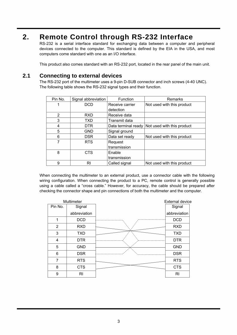
3
2. Remote Control through RS-232 Interface RS-232 is a serial interface standard for exchanging data between a computer and peripheral devices connected to the computer. This standard is defined by the EIA in the USA, and most computers come standard with one as an I/O interface. This product also comes standard with an RS-232 port, located in the rear panel of the main unit.
2.1 Connecting to external devices The RS-232 port of the multimeter uses a 9-pin D-SUB connector and inch screws (4-40 UNC). The following table shows the RS-232 signal types and their function.
Pin No. Signal abbreviation Function Remarks 1 DCD Receive carrier
detection Not used with this product
2 RXD Receive data 3 TXD Transmit data 4 DTR Data terminal ready Not used with this product 5 GND Signal ground 6 DSR Data set ready Not used with this product 7 RTS Request
transmission
8 CTS Enable transmission
9 RI Called signal Not used with this product
When connecting the multimeter to an external product, use a connector cable with the following wiring configuration. When connecting the product to a PC, remote control is generally possible using a cable called a “cross cable.” However, for accuracy, the cable should be prepared after checking the connector shape and pin connections of both the multimeter and the computer. Multimeter External device
Pin No. Signal
abbreviation
Signal
abbreviation 1 DCD DCD
2 RXD RXD
3 TXD TXD
4 DTR DTR
5 GND GND
6 DSR DSR
7 RTS RTS
8 CTS CTS
9 RI
RI

4
2.2 Communication system The multimeter uses a full-duplex communication system, and may begin sending a response message even while receiving a message. This is not a problem since external devices usually have a receive buffer. However, in the event of a problem, flow control should be carried out. This equipment performs hardware flow control. It is not equipped with other flow controls, and the hardware flow control cannot be disabled. When the input buffer becomes full, the RTS signal is held off when a message to the delimiter is received. After the received message is interpreted and processed, the RTS signal hold off is cancelled. The multimeter has a 256-byte input buffer. Therefore, care should be taken to avoid sending a single message that exceeds 256 bytes. The output buffer (“output queue” below) is 256 bytes. The product uses a full-duplex communication system and begins sending data as soon as output data has been prepared. Therefore, problems will not generally arise as a result of neglecting to keep an eye on the output queue. However, attention should be paid to the output queue when carrying out flow control. (Do not send commands to the multimeter that require a response exceeding 256 bytes.) To communicate via RS-232, set the remote I/F to RS-232. When communicating with an external device, it is necessary to coordinate the settings of the multimeter and the external device beforehand. The following settings can be implemented by selecting the RS menu in the utility system menu. (These settings cannot be made by remote control.) (1) Baud rate (RS: Rate) Select 300, 600, 1200, 2400, 4800, 9600 or 19200 (bps) (2) Parity bit (RS: Parity) Select NONE, EVEN or ODD (3) Stop bit (RS: Stop) Select 1 or 2 (4) Delimiter (RS: DELIM) Select CR+LF or LF (5) Data length Select either 7 bit or 8 bit For settings on the external device, see the instruction manual supplied with the product and change the settings to enable it to communicate with the multimeter. When the baud rate is set at a high speed, an overrun error may occur. Reduce the baud rate if this occurs.
5
2.3 Synchronization This product only provides synchronization by hardware flow control for serial communication with an external device. To perform synchronization with software, we recommend creating a remote program that queries the last message unit sent to the multimeter (i.e. a command that requests a response from the multimeter) and sends the next message once a response has been received from the multimeter. The *OPC? Query (see section 5.4. 4) can be used.
2.4 Remote/local control a. Local mode In local mode, operation of the multimeter is controlled by panel key operations. The REMOTE LED is off while in local mode. The multimeter enters local mode when the power is switched on. The following two methods are used to return the unit to local mode when it is operating in remote mode. ・Turn the power off and then on again.
・Press the (LOCAL) key. When the remote mode reverts to local mode, various settings that were made in remote mode, such as measurement condition settings, are continued uninterrupted. b. Remote mode In remote mode, operation of the multimeter is controlled by messages sent via an interface. All
key entries from the panel are disregarded except for the (LOCAL) key. While in remote mode, the REMOTE LED is lit. When a message is received from an external device, the multimeter shifts to the remote mode. When the first byte of the message is received, the instrument enters the remote mode. When switching to the remote mode, various settings made in the local mode, such as measurement condition settings, are continued uninterrupted. c. Local lockout mode The multimeter does not support local lockout mode while being controlled by the serial interface. If you require lockout, the GP-IB interface must be used.
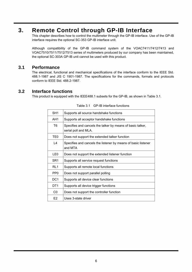
6
3. Remote Control through GP-IB Interface This chapter describes how to control the multimeter through the GP-IB interface. Use of the GP-IB interface requires the optional SC-353 GP-IB interface unit. Although compatibility of the GP-IB command system of the VOAC7411/7412/7413 and VOAC7510/7511/7512/7513 series of multimeters produced by our company has been maintained, the optional SC-303A GP-IB unit cannot be used with this product.
3.1 Performance The electrical, functional and mechanical specifications of the interface conform to the IEEE Std. 488.1-1987 and JIS C 1901-1987. The specifications for the commands, formats and protocols conform to IEEE Std. 488.2-1987.
3.2 Interface functions This product is equipped with the IEEE488.1 subsets for the GP-IB, as shown in Table 3.1.
Table 3.1 GP-IB interface functions
SH1 Supports all source handshake functions
AH1 Supports all acceptor handshake functions
T6 Specifies and cancels the talker by means of basic talker, serial poll and MLA.
TE0 Does not support the extended talker function
L4 Specifies and cancels the listener by means of basic listener and MTA
LE0 Does not support the extended listener function
SR1 Supports all service request functions
RL1 Supports all remote local functions
PP0 Does not support parallel polling
DC1 Supports all device clear functions
DT1 Supports all device trigger functions
C0 Does not support the controller function
E2 Uses 3-state driver
7
3.3 Connections Caution
・ When connecting or disconnecting cables, turn off the power to all of the devices connected to the GP-IB connector. ・ When operating the GP-IB system, turn on all the devices connected to the system bus. a. A maximum of 15 GP-IB devices can be connected to a single system. b. The maximum total length of the cables used to connect devices in the system is 20 m and 2 m × (the number of devices making up the system) or less. c. The length of each cable used in the system can be freely decided by the person in charge of configuring the system. However, if the length of a cable between devices is 4 m or more, adequate consideration should be given to the noise margin. d. The appropriate method for connecting cables (star, daisy chain, etc.) can be decided by the user. However, connections that create a ground loop should be avoided. e. The number of cables stacked at the connector located at the rear of the instrument should be limited to 3 due to mechanical strength. f. Use cables that conform to the IEEE 488.1 or JIS C 1901 standards. To improve the reliability of the system, we recommend using products that protect against EMC (i.e., connectors with metal housings). g. The GP-IB system is recommended for use in electrically and mechanically favorable environments. h. When configuring the system, refer to Section 6 and Appendix J of JIS C 1901-1987.
3.4 Instrument addresses Any address ranging from 0 to 30 can be selected for the listener and talker addresses. The listener and talker addresses (lower 5 bits of the code set) of the multimeter are shared. ・Valid code set for listener addresses: columns 0-3 and column 14 of code table 2 ・Valid code set for talker addresses: columns 0-5 and column 14 of code table 4 The factory set address is 9. ・MLA: column 9 of code table 2 ・MTA: column 9 of code table 4 Address settings are carried out in the GP-IB menu in the utility system menu. Addresses can be set at your discretion from 0-30.
8
3.5 Responses to interface messages 3.5.1 Remote/local control
Each function of the multimeter can be controlled remotely by messages sent via an interface. “Remote mode” involves the remote control of each multimeter function by messages sent via an interface. In contrast, “local mode” involves controlling the instrument via the operation of keys on the panel. This product is equipped with all the remote and local functions stipulated in IEEE Std. 488.1-1987 and JIS C 1901-1987. For details on switching between remote and local modes, refer to the section on RL functions in the specification. a. Local mode In local mode, the product is controlled by operating keys on the panel. The REMOTE LED is off when in local mode. The product enters local mode when the power is turned on. The following four ways are available to revert to local mode from remote mode (when using the GP-IB interface): ・Turn the power off and then on again. ・Set the REN line to false (electrically high level).
・Press the (LOCAL) key. ・Set the instrument to listener and send the GTL address command. When switching from remote mode to local mode, the various settings made in remote mode will continue uninterrupted. b. Remote mode In remote mode, the product is controlled by messages sent via the GP-IB interface. All panel key
input is disregarded except for the (LOCAL) key. The REMOTE LED is lit while in remote mode. To switch the operating mode of the multimeter from local to remote, it is necessary to set it to listener (MLA receive) with the REN line at “true” (electrically low level). Various settings made in local mode will continue uninterrupted. c. Local lockout mode This product enters the local lockout mode in either of the following cases: ・If the universal LLO command is received when in remote mode. ・When the instrument enters the remote mode after the universal LLO command is received. The local lockout mode prevents the mode from reverting to the local mode even if the operator
mistakenly presses the (LOCAL) key. Other than disregarding (LOCAL) key input, operations and responses are identical to the remote mode. To return the instrument to local mode from local lockout mode, set it to listener and transmit a GTL message. However, when the multimeter reverts to the remote mode again, it will enter the local lockout mode even if the LLO command is not received again.
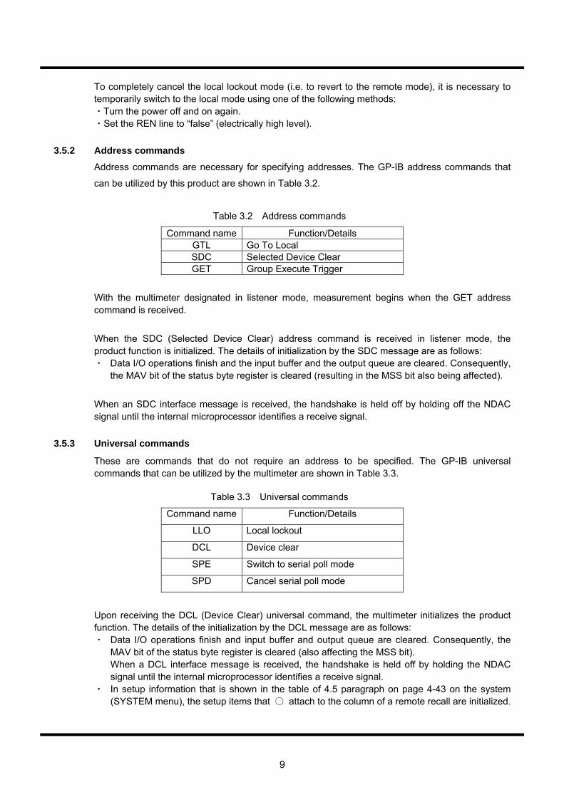
9
To completely cancel the local lockout mode (i.e. to revert to the remote mode), it is necessary to temporarily switch to the local mode using one of the following methods: ・Turn the power off and on again. ・Set the REN line to “false” (electrically high level).
3.5.2 Address commands
Address commands are necessary for specifying addresses. The GP-IB address commands that
can be utilized by this product are shown in Table 3.2.
Table 3.2 Address commands
Command name Function/Details GTL Go To Local SDC Selected Device Clear GET Group Execute Trigger
With the multimeter designated in listener mode, measurement begins when the GET address command is received.
When the SDC (Selected Device Clear) address command is received in listener mode, the product function is initialized. The details of initialization by the SDC message are as follows: ・ Data I/O operations finish and the input buffer and the output queue are cleared. Consequently,
the MAV bit of the status byte register is cleared (resulting in the MSS bit also being affected).
When an SDC interface message is received, the handshake is held off by holding off the NDAC signal until the internal microprocessor identifies a receive signal.
3.5.3 Universal commands
These are commands that do not require an address to be specified. The GP-IB universal commands that can be utilized by the multimeter are shown in Table 3.3. Table 3.3 Universal commands
Command name Function/Details
LLO Local lockout
DCL Device clear
SPE Switch to serial poll mode
SPD Cancel serial poll mode
Upon receiving the DCL (Device Clear) universal command, the multimeter initializes the product function. The details of the initialization by the DCL message are as follows: ・ Data I/O operations finish and input buffer and output queue are cleared. Consequently, the
MAV bit of the status byte register is cleared (also affecting the MSS bit). When a DCL interface message is received, the handshake is held off by holding the NDAC
signal until the internal microprocessor identifies a receive signal. ・ In setup information that is shown in the table of 4.5 paragraph on page 4-43 on the system
(SYSTEM menu), the setup items that attach to the column of a remote recall are initialized.
10
3.6 Delimiter When a <Response Message> is sent, LF or CR LF can be selected as a delimiter (i.e., a <Response Message Terminator>). EOI is always sent. The delimiter is specified through the GPIB menu in the system menu. (It cannot be specified via a remote interface). When a program message is received, the instrument recognizes LF, CR LF or EOI as the delimiter (<Program Message Terminator>). Note that this is independent of the delimiter setting.
3.7 I/O buffers This product is equipped with a 256-byte input buffer. When a delimiter is received, the product begins interpreting the commands in the input buffer even if the buffer is not full. The instrument will not receive the next command while commands are being interpreted or executed. The handshake at the head of a new message will be held off. The handshake is resumed once the commands have been interpreted and executed. When the input buffer becomes full, handshakes are temporarily held off, and are resumed after the commands in the message unit in the buffer have been interpreted and executed. The instrument is equipped with a 256-byte output buffer (output queue). When multiple query message units are batched into a single message, be careful that the total number of bytes of the response message does not exceed 256 bytes.
3.8 Manual settings required for remote operation Certain manual settings are required to remotely control the multimeter, which are shown the following Translator’s Note: There is some text missing here and also Table 3.4 seems to have disappeared. (1) GP-IB Address (Remote I/F: GPIB) Set an integer number 0-30. (2) Delimiter (RS: DELIM) Select either CR+LF or LF. (3) Old Command This command specifies whether to use the standard command system or a compatible
command system from previous models. The choices are OFF or ON. OFF : use the standard command system ON : use a compatible command system from a previous model
The Remote I/F must be set to GPIB similar to the configuration of the remote control I/F explained in Operation Manual section 4.9.3.
11
4. Remote Control by Ethernet When using a 10BaseT Ethernet, the multimeter can be controlled via a PC and network or through a direct connection. This connection uses the 10BaseT port at the back of the unit. The use of an Ethernet with the multimeter requires the optional SC-351 Ethernet port. This section explains the basic functions for controlling the multimeter by Ethernet interface. The multimeter can be connected to a PC via an Ethernet using a TCP/IP network interface. It can also be directly connected to a PC on a one-to-one basis using a cross network cable.
4.1 IP address settings The multimeter can be operated by either plugging it into a network or directly connecting it to a host computer. These connections require different types of cables. When connecting the multimeter directly to a PC one-to-one, a cross cable is necessary, and when connecting to a network, a straight cable is used. To communicate by CP/IP, set the Remote I/F to ETHER. The multimeter is configured to the factory default IP address. DHCP (Dynamic Host Configuration Protocol) and other automatic address resolution systems are not supported. Prior to connection, the user must adjust the IP address to suit the connection environment. For setting details, consult your network administrator. ・The default IP address is 192.168.1.100. ・The default mask is 255.255.255.0. ・The default gateway is 192.168.1.1. Implement the network settings according to the procedure below.
1. Press the key on the front panel of the multimeter.
2. Press the (SYSTEM) key at the bottom right of the front panel.
3. Change the display to IP: XXXXXXX using the keys of the RANGE
4. With the IP address flashing, press the key. 5. The flashing point moves right along the contents of IP: XXXXXXX, so select the IP:Address,
IP:Subnet and IP:Gateway using the keys on the key.
6. When changing the IP address from the above factory assigned default, press the key based on each condition in 5.
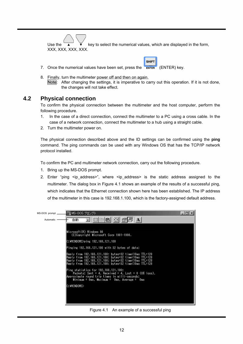
12
Use the key to select the numerical values, which are displayed in the form, XXX, XXX, XXX, XXX.
7. Once the numerical values have been set, press the (ENTER) key. 8. Finally, turn the multimeter power off and then on again. Note: After changing the settings, it is imperative to carry out this operation. If it is not done,
the changes will not take effect.
4.2 Physical connection To confirm the physical connection between the multimeter and the host computer, perform the following procedure. 1. In the case of a direct connection, connect the multimeter to a PC using a cross cable. In the
case of a network connection, connect the multimeter to a hub using a straight cable. 2. Turn the multimeter power on. The physical connection described above and the ID settings can be confirmed using the ping command. The ping commands can be used with any Windows OS that has the TCP/IP network protocol installed.
To confirm the PC and multimeter network connection, carry out the following procedure.
1. Bring up the MS-DOS prompt.
2. Enter “ping <ip_address>”, where <ip_address> is the static address assigned to the
multimeter. The dialog box in Figure 4.1 shows an example of the results of a successful ping,
which indicates that the Ethernet connection shown here has been established. The IP address
of the multimeter in this case is 192.168.1.100, which is the factory-assigned default address.
Figure 4.1 An example of a successful ping
MS-DOS prompt
Automatic
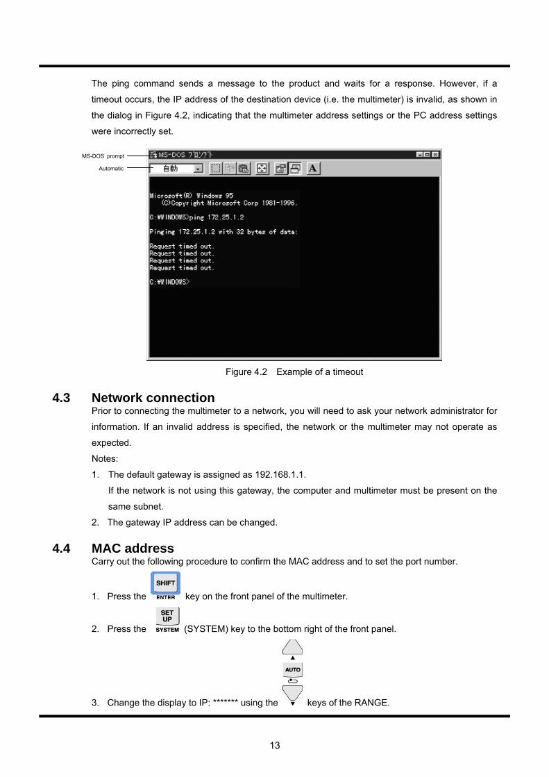
13
The ping command sends a message to the product and waits for a response. However, if a
timeout occurs, the IP address of the destination device (i.e. the multimeter) is invalid, as shown in
the dialog in Figure 4.2, indicating that the multimeter address settings or the PC address settings
were incorrectly set.
Figure 4.2 Example of a timeout
4.3 Network connection
Prior to connecting the multimeter to a network, you will need to ask your network administrator for
information. If an invalid address is specified, the network or the multimeter may not operate as
expected.
Notes:
1. The default gateway is assigned as 192.168.1.1.
If the network is not using this gateway, the computer and multimeter must be present on the
same subnet.
2. The gateway IP address can be changed.
4.4 MAC address Carry out the following procedure to confirm the MAC address and to set the port number.
1. Press the key on the front panel of the multimeter.
2. Press the (SYSTEM) key to the bottom right of the front panel.
3. Change the display to IP: ******* using the keys of the RANGE.
MS-DOS prompt
Automatic
14
4. With the IP address flashing, press the key.
The flashing point moves right along the contents of IP: *******, so select the IP:MAC Address
and IP:Port using the up/down keys on the key.
6. When changing the factory-assigned default settings, press the key based on each
condition in 5.
Use the key to select the numerical values, which are displayed in the form,
***.***.***.***.
7. Once the values have been set, press the (ENTER) key.
8. Finally, turn the multimeter power off and then on again.
Note: After changing the settings, it is imperative to carry out this operation. If it is not done,
the changes will not take effect.
4.5 Communication system Communication between the multimeter and PC utilizes TCP/IP. A TCP/IP connection is made
according to the following procedure.
Procedure
1. After switching the power on, the multimeter will wait for the set port number and a TCP/IP
connection request from the external device.
2. The external device will request a TCP/IP connection to the multimeter.
3. The multimeter will accept the TCP/IP connection request and establish a connection.
4. After establishing a TCP/IP connection, communication is carried out with the transmission and
receipt of a simple 7-bit ASCII character string.
5. A command or query is sent from the PC to the multimeter.
Command/query messages end with CR+LF or LF.
6. Commands/queries received by the multimeter are interpreted, executed, and in the case of a
query, a response is returned to the PC.
The set delimiter (CR+LF or LF) is added to the response.
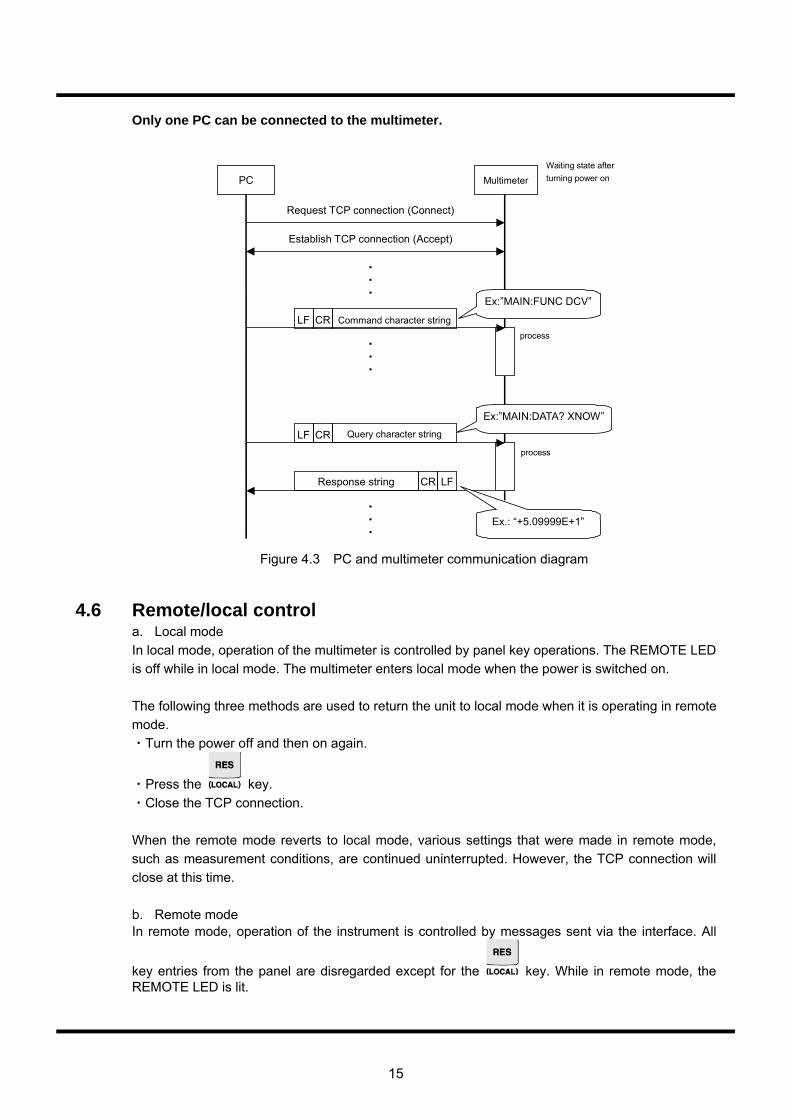
15
Only one PC can be connected to the multimeter.
PC Multimeter
Request TCP connection (Connect)
Establish TCP connection (Accept)
Command character stringCRLF
Query character string CRLF
・ ・ ・
・ ・ ・
Response string CR LF
・ ・ ・
Ex:”MAIN:FUNC DCV”
Ex:”MAIN:DATA? XNOW”
Ex.: “+5.09999E+1”
Waiting state after turning power on
process
process
Figure 4.3 PC and multimeter communication diagram
4.6 Remote/local control a. Local mode In local mode, operation of the multimeter is controlled by panel key operations. The REMOTE LED is off while in local mode. The multimeter enters local mode when the power is switched on. The following three methods are used to return the unit to local mode when it is operating in remote mode. ・Turn the power off and then on again.
・Press the key. ・Close the TCP connection. When the remote mode reverts to local mode, various settings that were made in remote mode, such as measurement conditions, are continued uninterrupted. However, the TCP connection will close at this time. b. Remote mode In remote mode, operation of the instrument is controlled by messages sent via the interface. All
key entries from the panel are disregarded except for the key. While in remote mode, the REMOTE LED is lit.
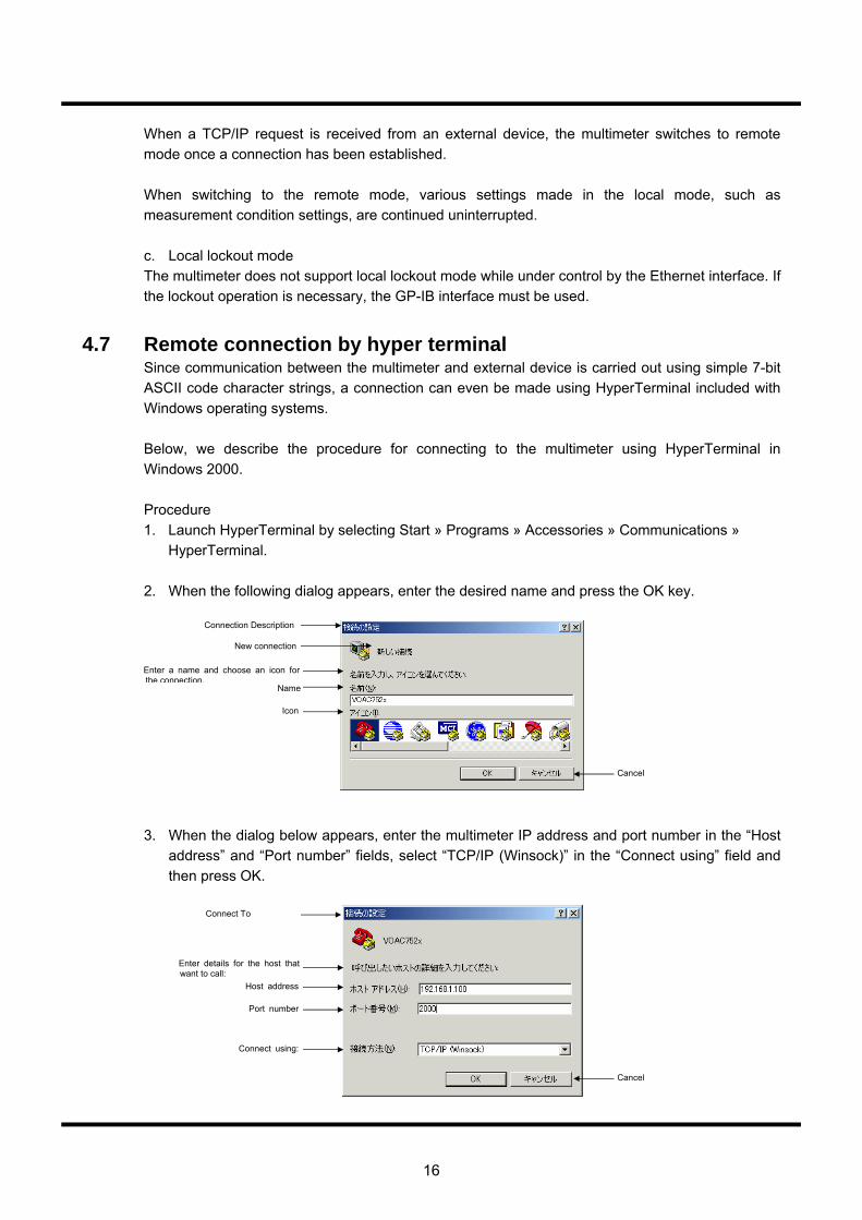
16
When a TCP/IP request is received from an external device, the multimeter switches to remote mode once a connection has been established. When switching to the remote mode, various settings made in the local mode, such as measurement condition settings, are continued uninterrupted. c. Local lockout mode The multimeter does not support local lockout mode while under control by the Ethernet interface. If the lockout operation is necessary, the GP-IB interface must be used.
4.7 Remote connection by hyper terminal Since communication between the multimeter and external device is carried out using simple 7-bit ASCII code character strings, a connection can even be made using HyperTerminal included with Windows operating systems. Below, we describe the procedure for connecting to the multimeter using HyperTerminal in Windows 2000. Procedure 1. Launch HyperTerminal by selecting Start » Programs » Accessories » Communications »
HyperTerminal. 2. When the following dialog appears, enter the desired name and press the OK key.
3. When the dialog below appears, enter the multimeter IP address and port number in the “Host address” and “Port number” fields, select “TCP/IP (Winsock)” in the “Connect using” field and then press OK.
Connection Description
Enter a name and choose an icon for the connection.
Name
Icon
Connect To
Connect using:
Port number
Host address
Enter details for the host that want to call:
New connection
Cancel
Cancel

17
4. HyperTerminal will launch, establishing a TCP/IP connection with the multimeter. Once a connection has been established, the multimeter’s REMOTE LED will light up.
If HyperTerminal presents an error message or the multimeter’s REMOTE LED does not light up, there may be a problem with the network settings, which will need to be checked.
5. Once a connection has been established, display the following dialog by selecting [File] »
[Properties]. Press the [ASCII Setup] key in the [Settings] tab.
6. When the following dialog is displayed, check the [Send line ends with line feeds] and [Echo typed characters locally] boxes and press OK.
7. The settings are now complete. You will now be able to control the multimeter by directly
entering commands and queries. Note: The multimeter does not support an escape sequence, so pressing Backspace or moving
the cursor will cause a command error.
Character delay:
VOAC752x Properties
Connect using
Port number
Host address
Change Icon…
Connect To
Cancel
Cancel
Settings Settings Function, arrow, and ctrl keys act as
Backspace key sends Ctrl+H, Space, Ctrl+H
Emulation Auto detect Telnet terminal ID: Backscroll buffer lines:Play sound when connecting or disconnecting Input translation… ASCII Setup…
ASCII Sending Send line ends with line feeds
Echo typed characters locally
ASCII Receiving Append line feeds to incoming line ends
Force incoming data to 7-bit ASCII
ASCII setup
Terminal keys
File, Edit, View
Connected
Auto detect
Hyper terminal
Call, Transfer, Help
milliseconds.
Line delay:
Wrap lines that exceed terminal width
Encode method
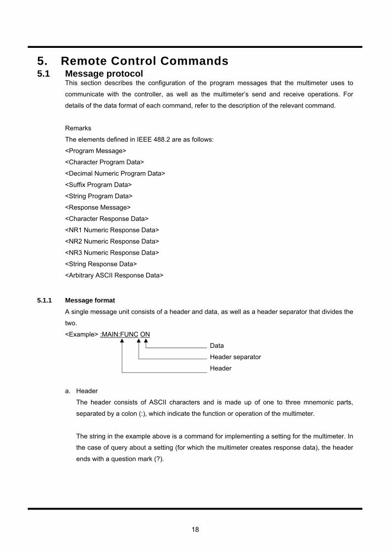
18
5. Remote Control Commands 5.1 Message protocol
This section describes the configuration of the program messages that the multimeter uses to
communicate with the controller, as well as the multimeter’s send and receive operations. For
details of the data format of each command, refer to the description of the relevant command.
Remarks
The elements defined in IEEE 488.2 are as follows:
<Program Message>
<Character Program Data>
<Decimal Numeric Program Data>
<Suffix Program Data>
<String Program Data>
<Response Message>
<Character Response Data>
<NR1 Numeric Response Data>
<NR2 Numeric Response Data>
<NR3 Numeric Response Data>
<String Response Data>
<Arbitrary ASCII Response Data>
5.1.1 Message format
A single message unit consists of a header and data, as well as a header separator that divides the
two.
<Example> :MAIN:FUNC ON
Data
Header separator
Header
a. Header
The header consists of ASCII characters and is made up of one to three mnemonic parts,
separated by a colon (:), which indicate the function or operation of the multimeter.
The string in the example above is a command for implementing a setting for the multimeter. In
the case of query about a setting (for which the multimeter creates response data), the header
ends with a question mark (?).
19
b. Header separator
This code separates the header and the data, and consists of a space code (ASCII character)
of at least one character. The white space character defined in IEEE 488.2 may also be used.
A command without data does not require the header separator. The data part cannot be
omitted except in the case of commands that do not have a data part.
c. Data
The data is a parameter that indicates the specific setting of the function specified in the header.
This part may consist of mnemonics (character strings) or numerical values. When multiple
parameters are required, a comma (,) is used to separate each parameter. The number of
parameters and their configuration depend on the command. For details on the data format,
see the description of the relevant command.
5.1.2 Multi-commands
Multiple message units can be assembled and configured as a single message.
Each message unit is separated by a semicolon (;).
(Example) :MAIN:DCBL:STAT ON ; :MAIN:DCBL:MOD ON
Messages unit
Message unit separator
Message unit
A device-specific command is a hierarchical command called a “compound command program
header.” For example, the parent command, POW, can be combined with subcommands, such as
SET, SLE and SIMM, to form a header (e.g., POW:SET or :POW:SLE). When message units that
have headers with a common parent command are combined into a single message, the parent
command in subsequent message units may be omitted.
(Example) :POW:SET INI;:POW:SLE OFF;:POW:SIMM can be written as
:POW:SET INI;SLE OFF;SIMM.
(If the parent command is omitted, be careful not to put the colon (:) in the header)
Below, this function will be expressed such that the POW parent command is designated as the
header path.
The header path designation is valid only within that message (up to the delimiter). In subsequent
messages, the parent command at the head of the message unit is designated as the header path.
Consequently, even if the colon (:) for the first character of the header is omitted in the head of the
message, it will be regarded as the parent command.

20
(Example) POW:SET INI is interpreted identically to :POW:SET INI.
If “:POW:SET INI;SLE OFF” is sent as a single message, it will be correctly interpreted, but if it is
split into two lines, “:POW:SET INI” and “SLE OFF,” an error will occur.
(The multimeter does not support a parent command called SLE)
When a message unit begins with a colon (:), that command is regarded as the parent command.
The header path is also updated, and that command becomes the new header path.
(Example) :POW:SET INI;SLE OFF;:SUB:AVG NUMB;AVG INI
↑ ↑
Header path is POW Header path is SUB
The multimeter does not retrace the command tree to search for commands. Consequently, when
combining message units with different parent commands into a single message, the head of a
message unit in which the header path needs to be switched must begin with a colon (:).
(Example) :POW:SET INI;SLE OFF; :SUB:AVG NUMB;AVG INI
↑
Cannot be omitted
The above header path rules do not apply to the common commands (*WAI, *OPC, etc.) defined in
IEEE 488.2.
The common commands are executed without regard for the header path. However, the header
path designation is not disrupted, and the previous header path is valid when interpreting the
following message unit after a common command.
(Example) :POW:SET INI;*WAI;SLE OFF;SIMM
Header path is POW
Common command, *WAI, is executed normally
5.1.3 Query
A message unit whose header ends with a question mark (?) is called a query, which is a
command used to inquire about settings, measurements results, and so on. Upon receipt of a
query, the multimeter creates a response message and stores it in the output queue.
When a new message is received while a response message (part of) remains in the output queue,
the contents of the output queue will be cleared, causing a query error (resulting in a service
request).
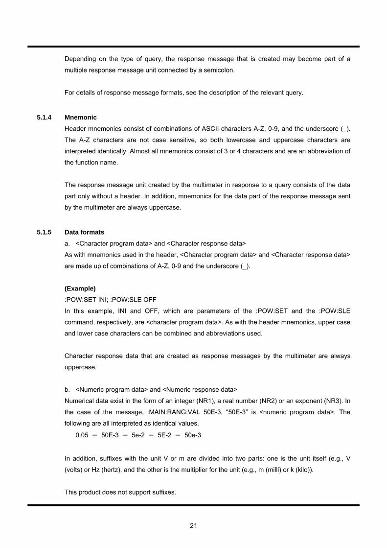
21
Depending on the type of query, the response message that is created may become part of a
multiple response message unit connected by a semicolon.
For details of response message formats, see the description of the relevant query.
5.1.4 Mnemonic
Header mnemonics consist of combinations of ASCII characters A-Z, 0-9, and the underscore (_).
The A-Z characters are not case sensitive, so both lowercase and uppercase characters are
interpreted identically. Almost all mnemonics consist of 3 or 4 characters and are an abbreviation of
the function name.
The response message unit created by the multimeter in response to a query consists of the data
part only without a header. In addition, mnemonics for the data part of the response message sent
by the multimeter are always uppercase.
5.1.5 Data formats
a. <Character program data> and <Character response data>
As with mnemonics used in the header, <Character program data> and <Character response data>
are made up of combinations of A-Z, 0-9 and the underscore (_).
(Example) :POW:SET INI; :POW:SLE OFF
In this example, INI and OFF, which are parameters of the :POW:SET and the :POW:SLE
command, respectively, are <character program data>. As with the header mnemonics, upper case
and lower case characters can be combined and abbreviations used.
Character response data that are created as response messages by the multimeter are always
uppercase.
b. <Numeric program data> and <Numeric response data>
Numerical data exist in the form of an integer (NR1), a real number (NR2) or an exponent (NR3). In
the case of the message, :MAIN:RANG:VAL 50E-3, “50E-3” is <numeric program data>. The
following are all interpreted as identical values.
0.05 = 50E-3 = 5e-2 = 5E-2 = 50e-3
In addition, suffixes with the unit V or m are divided into two parts: one is the unit itself (e.g., V
(volts) or Hz (hertz), and the other is the multiplier for the unit (e.g., m (milli) or k (kilo)).
This product does not support suffixes.
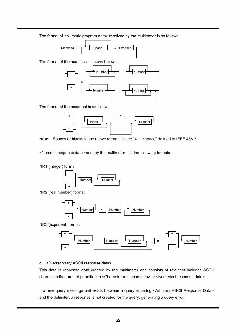
22
The format of <Numeric program data> received by the multimeter is as follows.
The format of the mantissa is shown below.
The format of the exponent is as follows.
Note: Spaces or blanks in the above format include “white space” defined in IEEE 488.2.
<Numeric response data> sent by the multimeter has the following formats.
NR1 (integer) format
NR2 (real number) format
NR3 (exponent) format
c. <Discretionary ASCII response data>
This data is response data created by the multimeter and consists of text that includes ASCII
characters that are not permitted in <Character response data> or <Numerical response data>.
If a new query message unit exists between a query returning <Arbitrary ASCII Response Data>
and the delimiter, a response is not created for the query, generating a query error.
Mantissa Space Exponent
+
-
Number Number
Number Number
.
.
Number
E
e
+
-
Blank
Number
+
- Number
Number
+
-
Number . Number
Number
+
-
Number . Number E
+
- Number
23
5.2 Status report structure 5.2.1 Service request (SRQ)
When an operation is completed or an error occurs, the multimeter outputs a service request (i.e.
sets the SRQ line to “L”) using the GP-IB interface.
While the bus line used for a service request has only one SRQ line (a wired OR connection), the
multimeter has multiple service request events. To identify the cause of a service request, the
controller must execute a serial poll or read the multimeter’s internal status register.
When using a serial interface or Ethernet interface, service requests and serial polls cannot be
used, so the controller must be programmed to read the multimeter’s internal status register as
required.
5.2.2 Status byte register
The status byte register enables serial polling via the GP-IB system bus or a readout using the
*STB? query, and is located in the final stage of the multimeter’s status information, which consists
of a hierarchal structure. The register consists of 8 bits with the following contents.
(bit 7) The multimeter does not use bit 7 of the status byte register, and is always set to 0.
RQS (bit 6) RQS is returned as bit 6 of the status byte of a serial poll response. RQS is set
when the logical sum of all bits changes from 0 to 1 as a result of the other bits in the status byte register (ESB, MAV,.., MEV) being masked by the service request enable register. RQS is cleared when the above logical sum changes from 0 to 1, the power is turned on or serial polling is executed.
MSS (bit 6) MSS is returned as bit 6 of the *STB? query. It reflects the logical sum of all bits
resulting from other bits in the status byte register (ESB, MAV,..,MEV) being masked by the service request enable register.
ESB (bit 5) ESB is returned as bit 5 of the serial poll or *STB? query response, and is a
summary message corresponding to the standard event status register. MAV (bit 4) MAV is returned as bit 4 of a serial poll or the STB? query response, and is a
summary message corresponding to the output queue. (bit 3) This product does not use bit 3 of the status byte register, and is always set to 0. (bit 2) This product does not use bit 2 of the status byte register, and is always set to 0. (bit 1) This product does not use bit 1 of the status byte register, and is always set to 0.
24
MEV (bit 0) MEV is returned as bit 0 of a serial poll or STB? query response, and is a summary message corresponding to the measurement event status register.
5.2.3 Service request enable register
The service request enable register masks the status byte register. Depending on the result of masking, the RQS or MSS bit is set. (Consequently, this register also affects a GP-IB service request.) The mask pattern set by the *SRE command can be read using the *SRE? query. Deciding whether or not to clear (i.e., set to 0) the contents of this register when the power is turned on can be determined using the * PSC command. This does not directly affect the GP-IB device clear message or the *CLS command.
5.2.4 Standard event status register This register can be read using the ESR? query. The logical sum of all bits resulting from masking the contents of this register by the standard event status enable register are reflected in the ESB bit of the status byte register. The contents of this register are cleared (i.e., set to 0) when the register is read by a CLS command or ESR? query. This register consists of 8 bits, the contents of which are shown below. PON (bit 7) After the power is turned on, this bit is set to 1. (bit 6) This product does not use bit 6, which is always set to 0. CME (bit 5) When a command error occurs, this bit is set to 1, indicating an error in the
command syntax. EXE (bit 4) When an execution error occurs, this bit is set to 1, indicating that the command
could not be executed or was not completed normally. DDE (bit 3) When a device-specific error occurs, this bit is set to 1. This is a summary
message of the Device Dependent Error (DDER) register. QYE (bit 2) When a query error occurs, this bit is set to 1. This bit indicates that an error has
occurred when the computer attempts to read a message from the multimeter without sending a query command, or when the next message is sent before the response message has been completely read.
(bit 1) This product does not use this bit, which is always set to 0. OPC (bit 0) When an operation is completed, this bit is set to 1. This bit supports
synchronization between the controller and the product using the *OPC command.

25
5.2.5 Standard event status enable register
This register masks the standard event status register. The ESB bit of the status byte register is set according to the results of masking. The mask pattern set by the *ESE command can be read using the *ESE? query. The *PSC command is used to determine whether or not to clear (i.e., set to 0) the contents of this register when the power is turned on. This does not affect the GP-IB device clear message or the *CLS command.
5.2.6 Output queue
The output queue is an output buffer for storing response messages to the controller. Appropriate response messages are stored in the output queue according to the type of query. The MAV bit of the status byte register is set to 1 as long as there is at least one byte of data in the output queue. The contents of this output queue are cleared (i.e., empty) when the power is turned on or the product clear command is executed. When the output queue is not empty and a new program message is sent before the controller reads all the data bytes, a query error occurs and the contents of the output queue are also cleared. When using a serial interface, serial polling cannot be used, rendering the MAV bit ineffective. (Once the MAV bit status has been read using the STB? query, the previous contents of the queue will have already been sent.) Additionally, since the multimeter uses full-duplex communication, it receives program messages even if the output queue is not empty (currently transmitting), without generating a query error.
5.2.7 Device-specific error occurrence event register (DDER) This register is an event register for reporting detailed DDE information. (bit 7) This product does not use bit 7 of the DDER register, which is always set to 0. SFE (bit 6) This bit indicates a framing error in the serial interface. SOE (bit 5) This bit indicates an overrun error in the serial interface. (bit 4) This product does not use bit 4 of the DDER register, which is always set to 0. HLE (bit 3) This bit indicates a comparator high-low limit setting error (H < L). LGZ (bit 2) This bit indicates a Log (0) error in the decibel computation result.
26
OVM (bit 1) This bit indicates an overflow error in the scaling computation result. LOV (bit 0) This bit indicates the occurrence of a limit overrun.
Using the DDER? query enables the current contents of the device-specific error occurrence event status register to be obtained. When the contents of the event status register are read, they are then cleared. Query syntax DDER? Response message <status> <Status> is a numeric value in the <NR1 numeric value response data> format ranging from 0 to 111, which weights the value of each bit in the device specific error occurrence event status register by an exponent of 2.
27
5.2.8 Device-specific error occurrence event enable register (DDEE)
This register is used to mask the device-specific error occurrence event status register. According to the masked results, the DDE bit of the standard event status register is set. It is possible to set the mask pattern using the DDEE command and to read it using the DDEE? query. Whether or not the contents of this register are cleared (set to 0) as the power is turned on is set using the *PSC command. This setting is not affected by the product clear or * CLS command. The DDEE command is used to set each bit of the device specific error occurrence event status enable register. It is possible to obtain the current contents of the device specific error occurrence event status enable register using the DDEE? query.
Command syntax
DDEE <mask_arg> <mask_arg> is a parameter necessary to set the device specific error occurrence event status enable register and is a numeric value ranging from 0 to 255 in the <numeric value program data> format. One meaning is assigned to each bit of the device specific error occurrence event status enable register. When a bit corresponding to the enable register is set to 1, the relevant event is enabled (affecting the DDE bit of the standard event status register). On the contrary, when a bit is set to 0, the relevant event is disabled (which does not affect the DDE bit).
Query syntax
DDEE?
Response message <mask>
<mask> is a numeric value ranging from 0 to 111 in the <NR1 numeric value response data> format, and is weighted by the exponentiation of 2 to the power of each bit in the device-specific event status enable register.
28
5.2.9 Measurement event status register (MESR)
This is an event register used to report the completion of a measurement and comparator results. The results of the logical sum of all bits resulting from masking the register contents with the measurement event status enable register are reflected in the MEV bit of the status byte register. The query for this register is “:MESR?”. The contents of this register are cleared (i.e., set to 0) when the power is turned on. Lout (bit 7) This bit is set to 1 if the measurement result is smaller than the lower limit value
when the comparator calculation is specified. Hout (bit 6) This bit is set to 1 if the measurement result is larger than the upper limit value
when the comparator calculation is specified. GO (bit 5) This bit is set to 1 when the measurement result is within the range of the upper
and lower limits when the comparator calculation is specified. (bit 4) This bit is not used in this product and is always set to 0. CAL (bit 3) This bit is set to 1 when the calibration is complete. STE (bit 2) This bit is set to 1 when the measurement data has been saved. SNE (bit 1) This bit is set to 1 when the number of measurements reaches the specified value
when statistic calculation is specified. SDR (bit 0) This bit is set to 1 when a measurement is complete. The current contents of the measurement event status register can be obtained using the MESR? query. Once the contents of the event status register have been read, they are then cleared.
Query syntax
MESR?
Response message <status>
<Status> is a numeric value ranging from 0 to 231 in the <NR1 numeric value response data> format, and is weighted by the exponentiation of 2 to the power of each bit in the measurement event status register.
29
5.2.10 Measurement event status enable register (MESE)
This register is used to mask the measurement event status register. The MEV bit of the status byte register is set according to the masked results. The mask pattern is set using the :MESE command and can be read using the MESE? query. The *PSC command can be used to determine whether to clear (=0) the contents of this register when the power is turned on. This setting is unaffected by the product clear or *CLS command.
Command syntax
MESE <mask_arg> <Mask_arg> is a parameter for setting the measurement event status enable register and is a numeric value ranging from 0 to 255 in the <numeric value program data> format. One meaning is assigned to each bit in the measurement event status register. When the bit corresponding to the enable register is set to 1, the relevant event is enabled (reflected in the status byte register). Conversely, when the bit is set to 0, the relevant event is disabled (not reflected in the status byte).
Query syntax
MESE?
Response message <mask>
<Mask> is a numeric value ranging from 0 to 231 in the <NR1 numeric value response data> format, and is weighted by the exponentiation of 2 to the power of each bit in the measurement event status enable register by an exponent of 2.
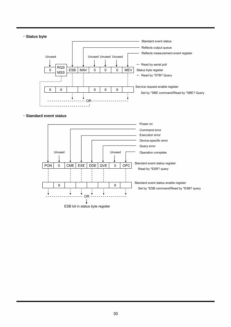
30
・Status byte
・Standard event status
0 ESB MAV 0 0 0 MEV
X X X XX
OR
Unused
RQS MSS
Unused Unused Unused
Standard event status
Reflects output queue
Reflects measurement event register
← Read by serial poll
Status byte register
← Read by *STB? Query
Service request enable register
Set by *SBE command/Read by *SBE? Query
PON CME EXE DDE QVE 0 OPC
XX
OR
Unused Unused
Execution error
Device-specific error
Query error
Standard event status register 0
Power on
Command error
Operation complete
Read by *ESR? query
Standard event status enable register
Set by *ESB command/Read by *ESB? query
ESB bit in status byte register

31
・Measurement event status
・DDE event register
Lout GO 0 CAL STE SNE SDR
X
OR
Unused Save
complete
Comparator result = H-OUT
Comparator result = GO
Number of statistic calculations has reached specified frequency
Measurement event status register Hout
Comparator result = L-OUT
Measurement complete
Read by MESR? query
Measurement event status enable register
Set by MESE command Read by MESE? query
MEV bit in status byte register
Adjustment complete
Unused
To DDE bit in standard event status register
0 SOE 0 HLE LGZ OVM LOV
X
OR
SFE
Unused
RS framing query
RS overrun error Comparator HL setting Error generated in decibel computation Overrun in scaling computation Scaling
X
32
5.3 Numeric program data This section describes the handling of numeric data in remote control commands. For commands from a PC to the multimeter, certain numeric program data parameters are obtained and converted into internal numeric data for the multimeter according to the following rules. 1. The number of valid digits in the mantissa is six. Mantissas that exceed this number are
rounded to the number of valid digits, with the digits exceeding this number being discarded. In such a case, an error will not occur.
Example 1: 1234567E1 => 123456E2 Example 2: 123.4567E1 => 123456E-2
2. The number of valid digits in the exponent is two. When this number is exceeded, a command error is generated. Example 3: 1.0E125 => error Example 4: 1.0E099 => OK
3. In addition to rules 1 and 2 above, each parameter has a predetermined upper and lower limit. If values exceeding these limits are input, the value will be rounded to the setting range or allowable setting range, and an execution error generated. There are a maximum total of four threshold values in terms of upper and lower limits: positive/negative for maximum absolute values, and positive/negative for minimum absolute values. Example 5: The following threshold values are set for the XREF of a differential calculation. Maximum absolute value threshold: –999.999E12 - +999.999E12 Minimum absolute value threshold: –000.001E-12 - +000.001E-12
4. Parameters that take only integers are set by rounding values expressed by mantissa + exponent to an integer. This does not generate an error. However, when the setting range or allowable setting range permitted by each parameter is exceeded, the value is rounded to within the range and an execution error generated. Example 6: The parameter for the :MAIN:FUNC command is a positive integer from 0-12
indicating the measurement function. Rounding to integers in this case is done as follows: 0.123 => 0 -45.6 => -45 0.789E3 => 789 Rounding to within the setting range or allowable setting range range is done as
follows: -45 => 0 789 => 12
33
5.4 Common commands This section describes those commands defined in the IEEE Std. 488.2 standard provided by the multimeter.
5.4.1 *IDN? query (Identification) The multimeter can be identified through the system interface using the *IDN? query.
Query syntax
*IDN?
Response message IWATSU, <model_number>, 0, <firmware_revision> <NL>
The response is composed of four fields separated by commas. Each field is has the following meaning.
Field 1 Manufacturer IWATSU Field 2 Model VOAC7520H , VOAC7521H, VOAC7522H or VOAC7523H Field 3 Serial number Always set to 0. This product does not support this field. Field 4 Firmware level ASCII numeric value (unsigned <NR2>)
Remarks
The response data consists of four fields in the <discretionary ASCII response data> format. Therefore, the *IDN? query must be the last query in the <program message>. If this rule is violated, a query error will be generated and the response message for queries after the *IDN? query will not be created or sent.

34
5.4.2 *RST commands (Reset : Initialization of the setting when the instrument was shipped)
When the multimeter receives the *RST command, it initializes the internal setup to the factory-set default values. However, settings for the RS-232, GP-IB and Ethernet interfaces remain unchanged.
Command syntax
*RST
35
5.4.3 *TST? query (Test : Execution of self-diagnosis)
When the multimeter receives the *TST? query, it carries out an internal test and stores the response, which indicates whether or not the test has been completed without error, in the output queue.
Query syntax
*TST?
Response message <result>
<Result> is in the <NR1 numeric value response data> format and ranges from 0 to 7, indicating test results. When all tests shown in the remarks below are passed, <result> is set to 0. In the event of a test error, an error code is returned. Error codes are numeric values in which the bits assigned by the test items shown below are weighted by an exponent of two.
・Simple AD converter test (bit 2) ・Simple SRAM test (bit 1) ・Consistency test of corrected data (bit 0)
36
5.4.4 *OPC command/*OPC? query (Operation Complete : Completion of device operation)
When the multimeter receives the *OPC command, it sets the operation completion message (OPC bit) in the standard event status register to 1 once all device operations specified by commands or queries sent prior to this command have been completed.
When the multimeter receives an *OPC? query, it stores the ASCII character, 1, in the output queue instead of setting the OPC bit in the standard event status register.
Command syntax
*OPC
Query syntax
*OPC?
Response message 1
The response message is a 1 in the <NR1 numeric value response data> format.
37
5.4.5 *WAI commands (Wait : Execution standby of command and query)
When the multimeter receives the *WAI command, it withholds the execution of subsequent commands and queries until all device operations specified by commands and queries sent prior to the *WAI command have been completed.
Command syntax
*WAI
38
5.4.6 *CLS command (Clear Status : Clearance of the standard event status register and the device specific event register)
The *CLS command clears both the standard event status register and the device specific event register of the multimeter. This command also clears the summary bit in the status byte register which reflects the contents of these registers and the queues.
Command syntax
*CLS
39
5.4.7 *ESE command/*ESE? query (Event Status Enable : Setting and Retrieval)
The *ESE command is used to set each bit in the standard event status enable register. The current contents of the standard event status enable register can be obtained using the *ESE? query.
Command syntax
*ESE <mask_arg>
<mask_arg> is a parameter for setting the standard event status enable register and is a numeric value in the <numeric value program data> format ranging from 0 to 255.
The standard event status register assigns one meaning to each bit. When a bit corresponding to the enable register is set to 1, the relevant event is enabled (i.e. is reflected in the status byte register). Conversely, when a bit is set to 0, the relevant event is disabled (i.e., is not reflected in the status byte register).
Query syntax
*ESE?
Response message <mask>
<mask> is a numeric value in the <NR1 numeric value response data> format ranging from 0 to 189, and is weighted by the exponentiation of 2 to the power of each bit in the standard event status enable register.
Remarks: Structure of standard event status enable register
Bit Weighting Meaning
7 128 PON - Power ON
6 64 (URQ) - Not used in the multimeter.
5 32 CME - Command error
4 16 EXE - Execution error
3 8 DDE - Device specific error
2 4 QYE - Query error
1 2 (RQC) - Not used in the multimeter.
0 1 OPC - Operation complete
Since the multimeter does not use bits 1 or 6, the maximum value of the response message will be 189 (=255 − 64 − 2) even if all bits of this register are set to 1.
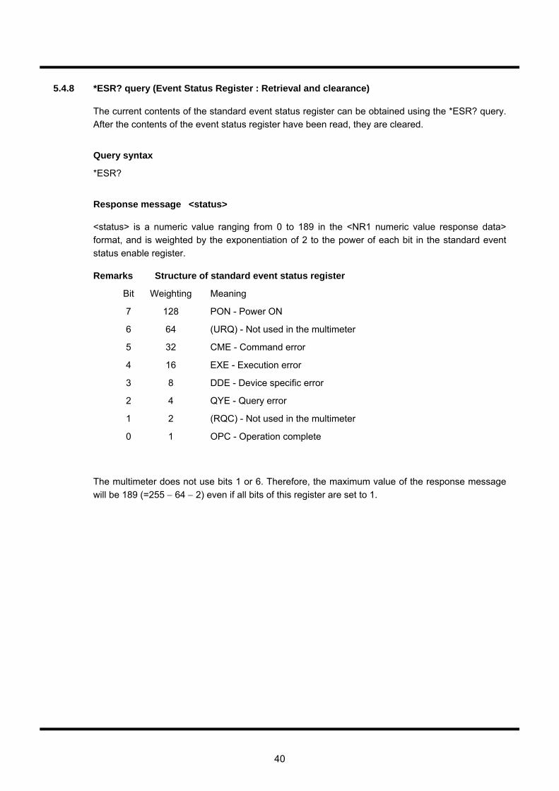
40
5.4.8 *ESR? query (Event Status Register : Retrieval and clearance)
The current contents of the standard event status register can be obtained using the *ESR? query. After the contents of the event status register have been read, they are cleared.
Query syntax
*ESR?
Response message <status>
<status> is a numeric value ranging from 0 to 189 in the <NR1 numeric value response data> format, and is weighted by the exponentiation of 2 to the power of each bit in the standard event status enable register.
Remarks Structure of standard event status register
Bit Weighting Meaning
7 128 PON - Power ON
6 64 (URQ) - Not used in the multimeter
5 32 CME - Command error
4 16 EXE - Execution error
3 8 DDE - Device specific error
2 4 QYE - Query error
1 2 (RQC) - Not used in the multimeter
0 1 OPC - Operation complete
The multimeter does not use bits 1 or 6. Therefore, the maximum value of the response message will be 189 (=255 − 64 − 2) even if all bits of this register are set to 1.
41
5.4.9 *PSC command/*PSC? query (Power on Status Clear : Automatic clearance when the power supply of various enable register is turned on)
The *PSC command controls the automatic clearing of the service request enable register, the standard event status enable register, and the event enable register groups specific to this product at power up.
The values set by the *PSC command can be obtained using the *PSC? query. If the value of the response data is 0, the status of each enable register will be retained even while the power is off. If the value of the response data is 1, the above enable registers will be cleared when the power is turned on again.
Command syntax
*PSC <psc_flag_arg>
<psc_flag_arg> is a parameter for setting the power on status clear flag, and is a numeric value in the <numeric value program data> format ranging from -32,767 to +32,767.
When the parameter is set to 0, the status of each enable register is retained even while the power is off. When the parameter is set to 1 (or any value other than 0), each enable register is cleared when the power is turned on again.
Query syntax
*PSC?
Response message <psc_flag>
<psc_flag> is a numeric value in the <NR1 numeric value response data> format that indicates the contents of the power on status clear flag, and is designated as 0 or 1.

42
5.4.10 *SRE command/*SRE? query (Service Request Enable : Setting and Retrieval)
The *SRE command is used to set each bit in the service request enable register. The current contents of the service request enable register can be obtained using the *SRE? query. Command syntax *SRE <mask_arg> <mask_arg> is a parameter for setting the service request enable register and is a numeric value in the <numeric value program data> format ranging from 0 to 255. The service request enable register assigns one meaning to each bit. When a bit corresponding to the enable register is set to 1, the relevant event is enabled (i.e., causes a service request to be generated). Conversely, when a bit is set to 0, the relevant event is disabled (i.e., does not cause a service request to be generated). Query syntax *SRE? Response message <mask> <mask> is a numeric value in the <NR1 numeric value response data> format ranging from 0 to 49, and is weighted by the exponentiation of 2 to the power of each bit in the standard event status enable register.
Remarks Structure of service request enable register Bit Weighting Meaning
7 128 XXX - Since the multimeter does not use this bit, it is always set to 0.
6 64 RQS/MSS - Request service/message summary status
5 32 ESB - Event status
4 16 MAV - Message available
3 8 XXX - Since the multimeter does not use this bit, it is always set to 0.
2 4 XXX - Since the multimeter does not use this bit, it is always set to 0.
1 2 XXX - Since the multimeter does not use this bit, tit is always set to 0.
0 1 MEV - Measurement event status
Response data is created assuming that bit 6 is always 0 regardless of the designation by the *SRE command parameter. However, note that this bit is always regarded as being enabled during actual operation.
Since the instrument does not use bits 1-3 or bit 7, and the response of bit 6 is 0, the maximum value of the response message is 49 (=32 + 16 + 1) even with all bits set to 1.
43
5.4.11 *STB? query (Status Byte : Retrieval)
The status byte and master summary status bit (MSS message) can be retrieved using the *STB? query.
Query syntax
*STB?
Response message <status>
<status> is a numeric value in the <NR1 numeric value response data> format ranging from 0 to 113, and is weighted by the exponentiation of 2 to the power of each bit in the standard event status enable register.
Remarks Structure of status byte register
Bit Weighting Meaning
7 128 XXX - Since the multimeter does not use this bit, it is always set to 0.
6 64 RQS/MSS - Request service/message summary status
5 32 ESB - Event status
4 16 MAV - Message available
3 8 XXX - Since the multimeter does not use this bit, it is always set to 0.
2 4 XXX - Since the multimeter does not use this bit, it is always set to 0.
1 2 XXX - Since the multimeter does not use this bit, it is always set to 0.
0 1 MEV - Measurement event status
The multimeter does not use bits 1 to 3 or bit 7. Therefore, the maximum value of the response message is 113 (= 64 + 32 + 16 + 1) even with all the bits in this register are set to 1.
When the contents of the status byte register are retrieved using the *STB? query, the MSS message is used for bit 6 instead of RQS in conformity with the IEEE488.2 standard. Other bits are the same as the values retrieved by serial polling.
The MSS message is obtained by logical OR of all bits, except for bit 6, after the contents of the status byte register are masked (logical AND) by the contents of the service request enable register.
The RQS message is basically retained in the status byte register until serial polling is performed. In contrast, the MSS message reflects the internal status of the product in real time.
44
5.4.12 *TRG command (Trigger : Execution of measurement)
The multimeter implements a measurement when it receives the *TRG command.
Command syntax
*TRG
45
5.4.13 *RCL command (Recall : Setup information)
The setup information saved in the internal memory of the multimeter can be recalled using the *RCL <register_number_arg> command.
Command syntax
*RCL <register_number_arg>
<register_number_arg> is a parameter for setting the number of the file to be recalled and is a numeric value in the <numeric value program data> format ranging from 0 to 9. This parameter specifies a number equivalent to the setup number selected by the save/recall operation during local operation.
Remarks
If <register_number_arg> is omitted, a command error will be generated.
If <register_number_arg> is rounded to an integer of 11 or more, an execution error will be generated and the recall operation will not be performed.
46
5.4.14 *SAV command (Save : Setup information)
The setup information is saved to the multimeter’s internal memory using the *SAV <register_number_arg> command.
Command syntax
*SAV <register_number>
<register_number_arg> is a parameter for setting the number of the file to be saved, and is a numeric value in the <numeric value program data> format ranging from 0 to 9. This parameter specifies a number equivalent to the setup number selected by the save/recall operation during local operation.
Remarks
If <register_number_arg> is omitted, a command error will be generated and the save operation will not executed.
If <register_number_arg> is rounded to an integer of 11 or more, an execution error will be generated and the save operation will not be performed.
47
5.5 Relationship between MAIN and SUB measurement functions Remote commands in the multimeter include :MAIN and SUB related commands. This section describes these commands and the relationship between their measurement functions.
5.5.1 Settings related commands/queries
For remote commands, the subcommands of measurement functions involved in the parent command hierarchy, such as DCV and ACV, or MAIN and SUB, are more or less common. These parameters are retained for each measurement function. For the Get and Set commands and queries for these parameters, MAIN and SUB operate as aliases of the measurement function currently being measured. In other words, when the parent command hierarchy involves MAIN or SUB, settings are configured for measurement functions assigned by the :MAIN and SUB side. Example: When the MAIN side measurement function is DCV, the following two commands are exactly the same. :MAIN:SCAL:STAT OFF :DCV:SCAL:STAT OFF
5.5.2 Control-related commands/queries
The following commands/queries, which are associated with operation control, are only valid when the parent command hierarchy involves MAIN or SUB. When the parent command hierarchy involves measurement functions such as DCV and ACV, these commands will generate error messages. Example: The following commands and queries are valid. :MAIN:FUNC/FUNC? :MAIN:DATA? :MAIN:MEAS? :SUB:FUNC/FUNC? :SUB:DATA? :SUB:MEAS?
48
5.6 Device-specific commands This section explains the device-specific commands provided by the multimeter. Device-specific commands related to status reports are described in Section 5.2. For common commands provided by the multimeter, refer to Section 5.4.
5.6.1 :MAIN related commands
5.6.1.1 :MAIN:DATA? (Retrieval of the latest measurement result)
This command retrieves the latest measurement result. If the DATA query is reissued without sampling after retrieving the previous measurement using the DATA query, the same value as the previous one is returned. Query syntax :MAIN:DATA? Parameter Parameters
<Numeric program data> format
<Character program data> format
0 XNOW 1 MAX 2 MIN 3 AVER 4 SIG
Response message See “Response messages for measurement results” in Section 5.7.
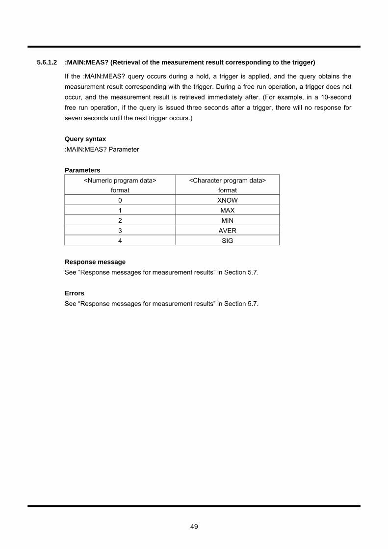
49
5.6.1.2 :MAIN:MEAS? (Retrieval of the measurement result corresponding to the trigger)
If the :MAIN:MEAS? query occurs during a hold, a trigger is applied, and the query obtains the measurement result corresponding with the trigger. During a free run operation, a trigger does not occur, and the measurement result is retrieved immediately after. (For example, in a 10-second free run operation, if the query is issued three seconds after a trigger, there will no response for seven seconds until the next trigger occurs.) Query syntax :MAIN:MEAS? Parameter Parameters
<Numeric program data> format
<Character program data> format
0 XNOW 1 MAX 2 MIN 3 AVER 4 SIG
Response message See “Response messages for measurement results” in Section 5.7. Errors See “Response messages for measurement results” in Section 5.7.
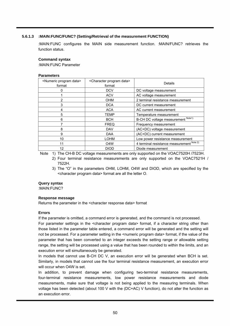
50
5.6.1.3 :MAIN:FUNC/FUNC? (Setting/Retrieval of the measurement FUNCTION)
:MAIN:FUNC configures the MAIN side measurement function. :MAIN/FUNC? retrieves the function status. Command syntax :MAIN:FUNC Parameter Parameters
<Numeric program data> format
<Character program data> format
Details
0 DCV DC voltage measurement 1 ACV AC voltage measurement 2 OHM 2 terminal resistance measurement 3 DCA DC current measurement 4 ACA AC current measurement 5 TEMP Temperature measurement 6 BCH B-CH DC voltage measurement Note1) 7 FREQ Frequency measurement 8 DAV (AC+DC) voltage measurement 9 DAA (AC+DC) current measurement
10 LOHM Low power resistance measurement 11 O4W 4 terminal resistance measurement Note 2) 12 DIOD Diode measurement
Note 1) The CH-B DC voltage measurements are only supported on the VOAC7520H /7523H. 2) Four terminal resistance measurements are only supported on the VOAC7521H /
7522H. 3) The “O” in the parameters OHM, LOHM, O4W and DIOD, which are specified by the
<character program data> format are all the letter O. Query syntax :MAIN:FUNC? Response message Returns the parameter in the <character response data> format Errors If the parameter is omitted, a command error is generated, and the command is not processed. For parameter settings in the <character program data> format, if a character string other than those listed in the parameter table entered, a command error will be generated and the setting will not be processed. For a parameter setting in the <numeric program data> format, if the value of the parameter that has been converted to an integer exceeds the setting range or allowable setting range, the setting will be processed using a value that has been rounded to within the limits, and an execution error will simultaneously be generated. In models that cannot use B-CH DC V, an execution error will be generated when BCH is set. Similarly, in models that cannot use the four terminal resistance measurement, an execution error will occur when O4W is set. In addition, to prevent damage when configuring two-terminal resistance measurements, four-terminal resistance measurements, low power resistance measurements and diode measurements, make sure that voltage is not being applied to the measuring terminals. When voltage has been detected (about 100 V with the (DC+AC) V function), do not alter the function as an execution error.
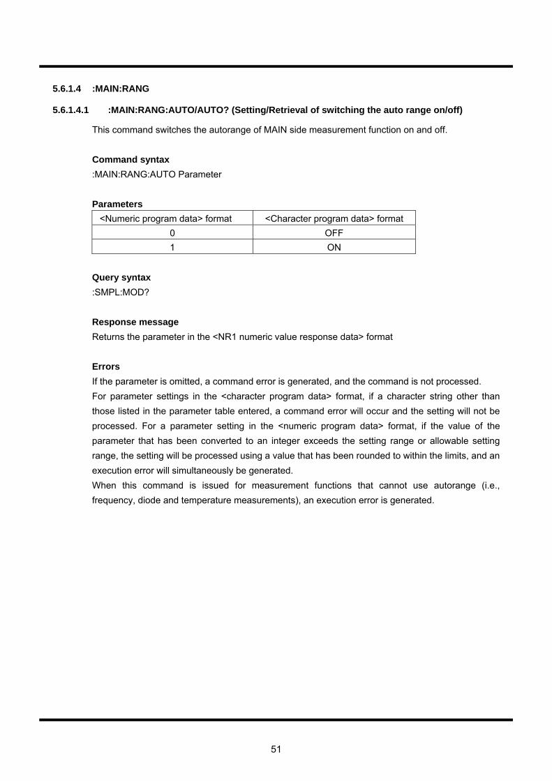
51
5.6.1.4 :MAIN:RANG
5.6.1.4.1 :MAIN:RANG:AUTO/AUTO? (Setting/Retrieval of switching the auto range on/off)
This command switches the autorange of MAIN side measurement function on and off. Command syntax :MAIN:RANG:AUTO Parameter Parameters
<Numeric program data> format <Character program data> format 0 OFF 1 ON
Query syntax :SMPL:MOD? Response message Returns the parameter in the <NR1 numeric value response data> format Errors If the parameter is omitted, a command error is generated, and the command is not processed. For parameter settings in the <character program data> format, if a character string other than those listed in the parameter table entered, a command error will occur and the setting will not be processed. For a parameter setting in the <numeric program data> format, if the value of the parameter that has been converted to an integer exceeds the setting range or allowable setting range, the setting will be processed using a value that has been rounded to within the limits, and an execution error will simultaneously be generated. When this command is issued for measurement functions that cannot use autorange (i.e., frequency, diode and temperature measurements), an execution error is generated.
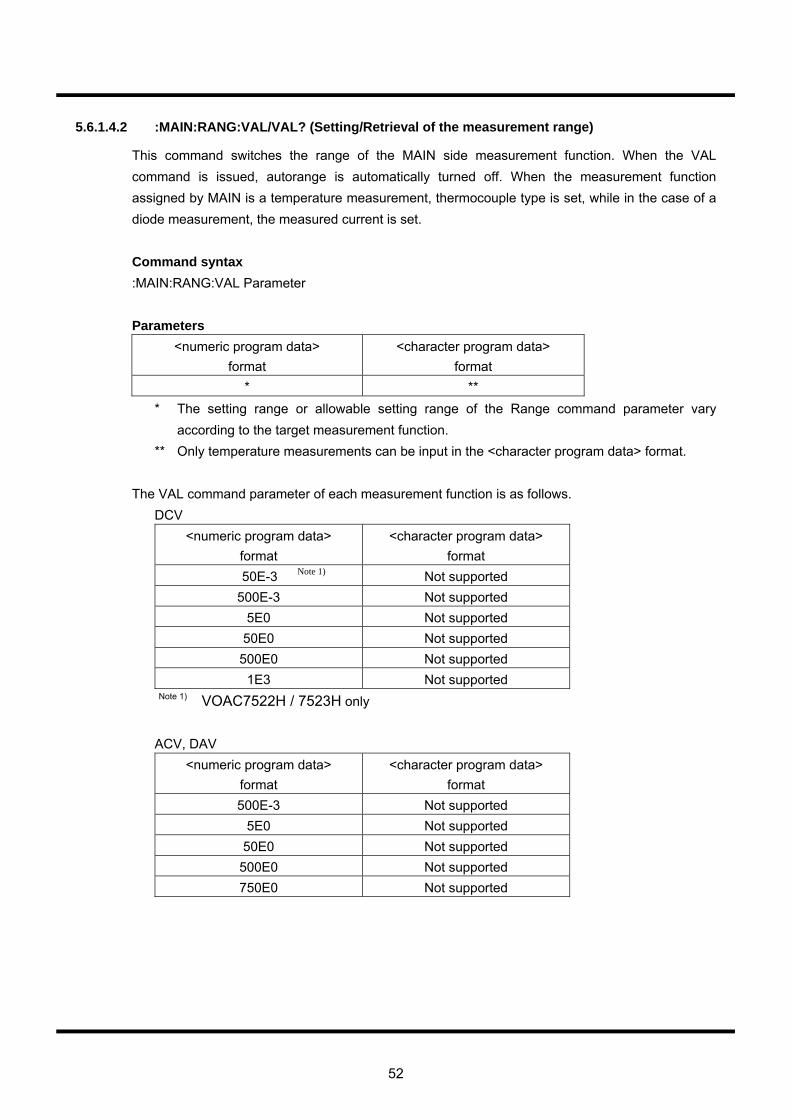
52
5.6.1.4.2 :MAIN:RANG:VAL/VAL? (Setting/Retrieval of the measurement range)
This command switches the range of the MAIN side measurement function. When the VAL command is issued, autorange is automatically turned off. When the measurement function assigned by MAIN is a temperature measurement, thermocouple type is set, while in the case of a diode measurement, the measured current is set. Command syntax :MAIN:RANG:VAL Parameter Parameters
<numeric program data> format
<character program data> format
* ** * The setting range or allowable setting range of the Range command parameter vary
according to the target measurement function. ** Only temperature measurements can be input in the <character program data> format.
The VAL command parameter of each measurement function is as follows.
DCV <numeric program data>
format <character program data>
format 50E-3 Note 1) Not supported
500E-3 Not supported 5E0 Not supported
50E0 Not supported 500E0 Not supported
1E3 Not supported Note 1) VOAC7522H / 7523H only
ACV, DAV <numeric program data>
format <character program data>
format 500E-3 Not supported
5E0 Not supported 50E0 Not supported 500E0 Not supported 750E0 Not supported
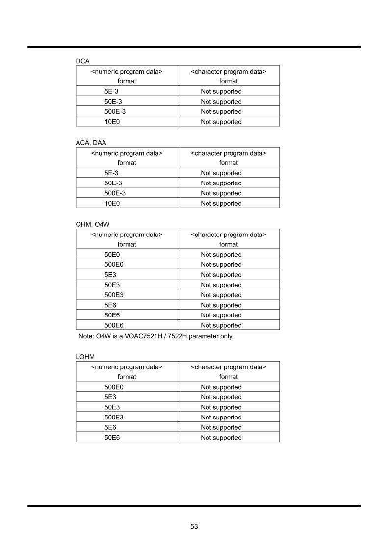
53
DCA <numeric program data>
format <character program data>
format 5E-3 Not supported 50E-3 Not supported 500E-3 Not supported 10E0 Not supported
ACA, DAA
<numeric program data> format
<character program data> format
5E-3 Not supported 50E-3 Not supported 500E-3 Not supported 10E0 Not supported
OHM, O4W
<numeric program data> format
<character program data> format
50E0 Not supported 500E0 Not supported 5E3 Not supported 50E3 Not supported 500E3 Not supported 5E6 Not supported 50E6 Not supported 500E6 Not supported
Note: O4W is a VOAC7521H / 7522H parameter only. LOHM
<numeric program data> format
<character program data> format
500E0 Not supported 5E3 Not supported 50E3 Not supported 500E3 Not supported 5E6 Not supported 50E6 Not supported
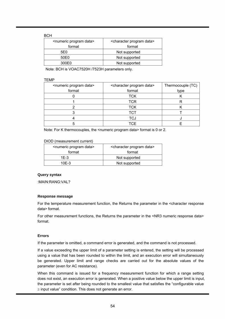
54
BCH <numeric program data>
format <character program data>
format 5E0 Not supported 50E0 Not supported 300E0 Not supported
Note: BCH is VOAC7520H /7523H parameters only.
TEMP <numeric program data>
format <character program data>
format Thermocouple (TC)
type 0 TCK K 1 TCR R 2 TCK K 3 TCT T 4 TCJ J 5 TCE E
Note: For K thermocouples, the <numeric program data> format is 0 or 2.
DIOD (measurement current) <numeric program data>
format <character program data>
format 1E-3 Not supported 10E-3 Not supported
Query syntax
:MAIN:RANG:VAL?
Response message
For the temperature measurement function, the Returns the parameter in the <character response data> format.
For other measurement functions, the Returns the parameter in the <NR3 numeric response data> format.
Errors
If the parameter is omitted, a command error is generated, and the command is not processed.
If a value exceeding the upper limit of a parameter setting is entered, the setting will be processed using a value that has been rounded to within the limit, and an execution error will simultaneously be generated. Upper limit and range checks are carried out for the absolute values of the parameter (even for AC resistance).
When this command is issued for a frequency measurement function for which a range setting does not exist, an execution error is generated. When a positive value below the upper limit is input, the parameter is set after being rounded to the smallest value that satisfies the “configurable value ≥ input value” condition. This does not generate an error.

55
5.6.1.5 :MAIN:REL
5.6.1.5.1 :MAIN:REL:STAT/STAT? (Switching the differential calculation on/off)
This command switches the differential calculation of MAIN side measurement functions on and off. When the differential calculation is switched from off to on, calculation of the measurement immediately following is initialized as XREF. Command syntax :MAIN:REL:STAT Parameter Parameters
<numeric program data> format
<character program data> format
0 OFF 1 ON
Query syntax :MAIN:REL:STAT? Response message Parameters are returned in the <NR1 numeric response data> format. Errors If the parameter is omitted, a command error is generated, and the command is not processed.
For a parameter setting in the <character program data> format, if a character string other than the parameters shown in the table is entered, a command error is generated and the setting is not processed. If a value exceeding the upper limit of a parameter setting is entered, the setting will be processed using a value that has been rounded to within the limit, and an execution error will simultaneously be generated. For a parameter setting in the <numeric program data> format, if the value of a parameter that has been converted to an integer exceeds the setting range or allowable setting range, the setting will be processed using a value that has been rounded to within the limits, and an execution error will simultaneously be generated.
56
5.6.1.5.2 :MAIN:REL:XREF/XREF? (Setting/Retrieval of the XREF parameter of the differential
calculation)
:MAIN:REL sets the XREF parameter of a differential calculation in a MAIN side measurement function. :MAIN:XREF? retrieves the parameter status. Command syntax :MAIN:REL:XREF Parameter Parameters
<numeric program data> format
-999.999E12 to 999.999E12
Query syntax :MAIN:REL:XREF? Response message Returns the parameter in the <NR3 numeric response data> format Errors If the parameter is omitted, a command error is generated, and the command is not processed. If a parameter exceeding the setting range or allowable setting range is entered, the setting will be processed using a value that has been rounded to within the limits, and an execution error will simultaneously be generated.
57
5.6.1.5.3 :MAIN:REL:XINI (The issue of the request to initialize in the XREF parameter of the
differential calculation)
This command issues a request to initialize the XREF parameter in a differential calculation for a MAIN side measurement function. After issuing this command, the initial sampling result is set as the XREF parameter. Command syntax :MAIN:REL:XINI

58
5.6.1.6 :MAIN:AVG
5.6.1.6.1 :MAIN:AVG:STAT/STAT? (Setting/Retrieval of switching the Moving Average calculation
on/off)
This command switches the Main side Moving Average calculation on and off. Command syntax :MAIN:AVG:STAT Parameter Parameters
<numeric program data> format
<character program data> format
0 OFF 1 ON
Query syntax :MAIN:AVG:STAT? Response message Parameters returns in the <NR1 numeric response data> format Errors If the parameter is omitted, a command error is generated, and the command is not processed. For a parameter setting in the <character program data> format, if a character string other than the parameters shown in the table above is entered, a command error is generated and the setting is not processed. For a parameter setting in the <numeric program data> format, if the value of a parameter that has been converted to an integer exceeds the setting range or allowable setting range, the setting will be processed using a value that has been rounded to within the limits, and an execution error will simultaneously be generated.
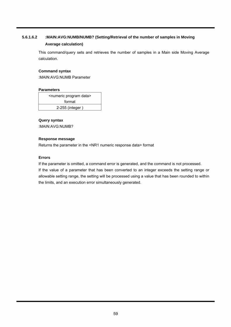
59
5.6.1.6.2 :MAIN:AVG:NUMB/NUMB? (Setting/Retrieval of the number of samples in Moving
Average calculation)
This command/query sets and retrieves the number of samples in a Main side Moving Average calculation. Command syntax :MAIN:AVG:NUMB Parameter Parameters
<numeric program data> format
2-255 (integer ) Query syntax :MAIN:AVG:NUMB? Response message Returns the parameter in the <NR1 numeric response data> format Errors If the parameter is omitted, a command error is generated, and the command is not processed. If the value of a parameter that has been converted to an integer exceeds the setting range or allowable setting range, the setting will be processed using a value that has been rounded to within the limits, and an execution error simultaneously generated.

60
5.6.1.6.3 :MAIN:AVG:INIT (Initialization of the sampling results in Moving Average calculation)
This command initializes the past sampling results of a Main side moving average calculation. Command syntax :MAIN:AVG:INIT
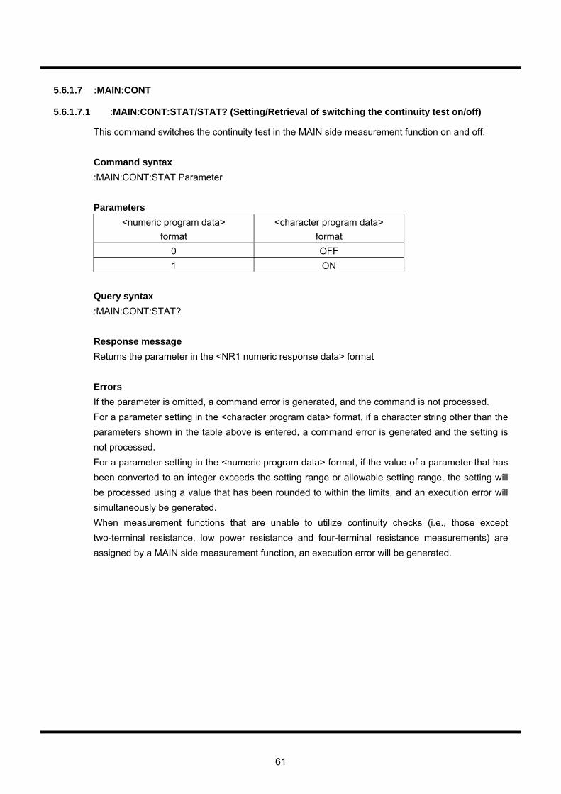
61
5.6.1.7 :MAIN:CONT
5.6.1.7.1 :MAIN:CONT:STAT/STAT? (Setting/Retrieval of switching the continuity test on/off)
This command switches the continuity test in the MAIN side measurement function on and off. Command syntax :MAIN:CONT:STAT Parameter Parameters
<numeric program data> format
<character program data> format
0 OFF 1 ON
Query syntax :MAIN:CONT:STAT? Response message Returns the parameter in the <NR1 numeric response data> format Errors If the parameter is omitted, a command error is generated, and the command is not processed. For a parameter setting in the <character program data> format, if a character string other than the parameters shown in the table above is entered, a command error is generated and the setting is not processed. For a parameter setting in the <numeric program data> format, if the value of a parameter that has been converted to an integer exceeds the setting range or allowable setting range, the setting will be processed using a value that has been rounded to within the limits, and an execution error will simultaneously be generated. When measurement functions that are unable to utilize continuity checks (i.e., those except two-terminal resistance, low power resistance and four-terminal resistance measurements) are assigned by a MAIN side measurement function, an execution error will be generated.
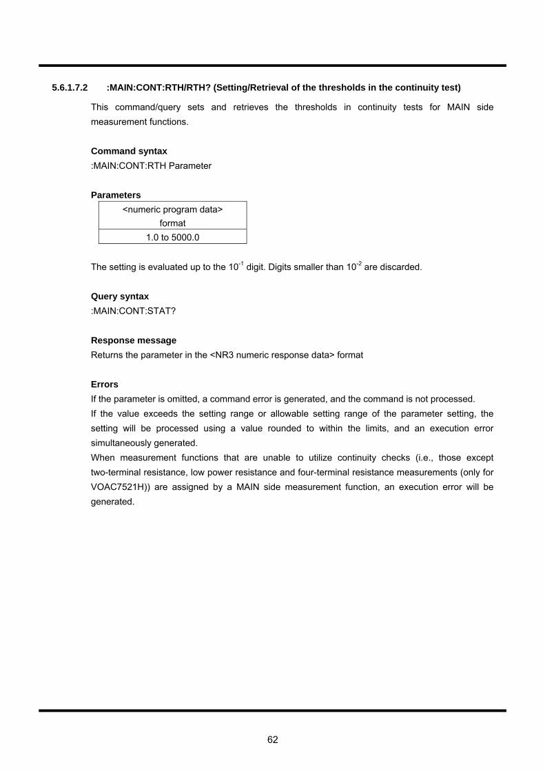
62
5.6.1.7.2 :MAIN:CONT:RTH/RTH? (Setting/Retrieval of the thresholds in the continuity test)
This command/query sets and retrieves the thresholds in continuity tests for MAIN side measurement functions. Command syntax :MAIN:CONT:RTH Parameter Parameters
<numeric program data> format
1.0 to 5000.0 The setting is evaluated up to the 10-1 digit. Digits smaller than 10-2 are discarded. Query syntax :MAIN:CONT:STAT? Response message Returns the parameter in the <NR3 numeric response data> format Errors If the parameter is omitted, a command error is generated, and the command is not processed. If the value exceeds the setting range or allowable setting range of the parameter setting, the setting will be processed using a value rounded to within the limits, and an execution error simultaneously generated. When measurement functions that are unable to utilize continuity checks (i.e., those except two-terminal resistance, low power resistance and four-terminal resistance measurements (only for VOAC7521H)) are assigned by a MAIN side measurement function, an execution error will be generated.
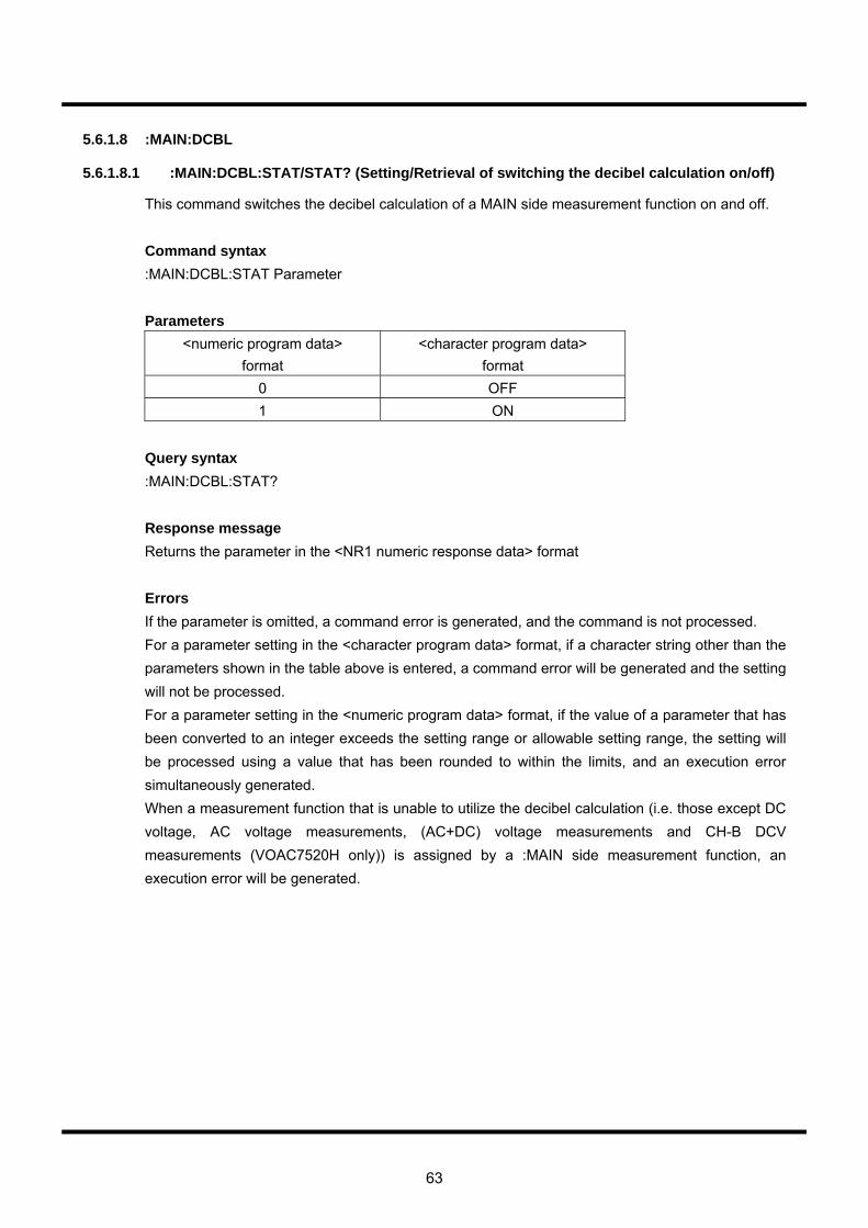
63
5.6.1.8 :MAIN:DCBL
5.6.1.8.1 :MAIN:DCBL:STAT/STAT? (Setting/Retrieval of switching the decibel calculation on/off)
This command switches the decibel calculation of a MAIN side measurement function on and off. Command syntax :MAIN:DCBL:STAT Parameter Parameters
<numeric program data> format
<character program data> format
0 OFF 1 ON
Query syntax :MAIN:DCBL:STAT? Response message Returns the parameter in the <NR1 numeric response data> format Errors If the parameter is omitted, a command error is generated, and the command is not processed. For a parameter setting in the <character program data> format, if a character string other than the parameters shown in the table above is entered, a command error will be generated and the setting will not be processed. For a parameter setting in the <numeric program data> format, if the value of a parameter that has been converted to an integer exceeds the setting range or allowable setting range, the setting will be processed using a value that has been rounded to within the limits, and an execution error simultaneously generated. When a measurement function that is unable to utilize the decibel calculation (i.e. those except DC voltage, AC voltage measurements, (AC+DC) voltage measurements and CH-B DCV measurements (VOAC7520H only)) is assigned by a :MAIN side measurement function, an execution error will be generated.
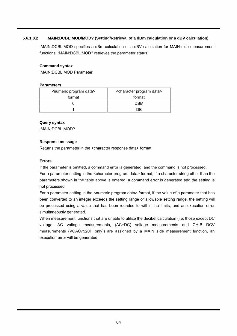
64
5.6.1.8.2 :MAIN:DCBL:MOD/MOD? (Setting/Retrieval of a dBm calculation or a dBV calculation)
:MAIN:DCBL:MOD specifies a dBm calculation or a dBV calculation for MAIN side measurement functions. :MAIN:DCBL:MOD? retrieves the parameter status. Command syntax :MAIN:DCBL:MOD Parameter Parameters
<numeric program data> format
<character program data> format
0 DBM 1 DB
Query syntax :MAIN:DCBL:MOD? Response message Returns the parameter in the <character response data> format Errors If the parameter is omitted, a command error is generated, and the command is not processed. For a parameter setting in the <character program data> format, if a character string other than the parameters shown in the table above is entered, a command error is generated and the setting is not processed. For a parameter setting in the <numeric program data> format, if the value of a parameter that has been converted to an integer exceeds the setting range or allowable setting range, the setting will be processed using a value that has been rounded to within the limits, and an execution error simultaneously generated. When measurement functions that are unable to utilize the decibel calculation (i.e. those except DC voltage, AC voltage measurements, (AC+DC) voltage measurements and CH-B DCV measurements (VOAC7520H only)) are assigned by a MAIN side measurement function, an execution error will be generated.
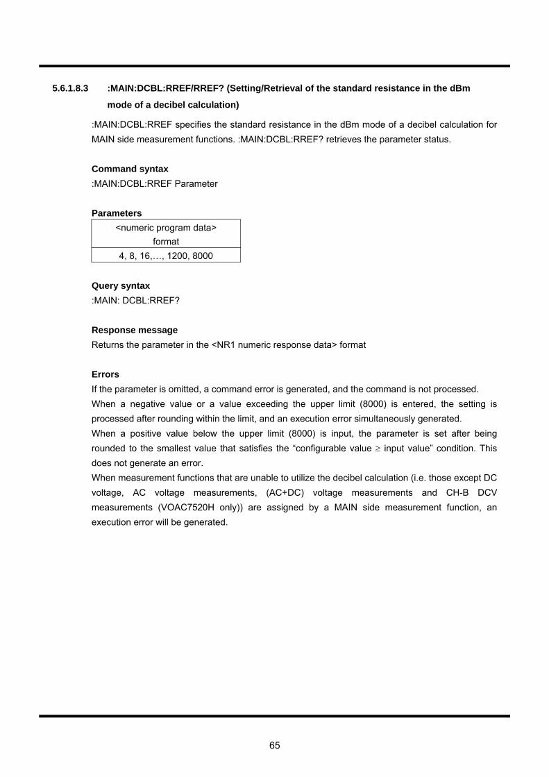
65
5.6.1.8.3 :MAIN:DCBL:RREF/RREF? (Setting/Retrieval of the standard resistance in the dBm
mode of a decibel calculation)
:MAIN:DCBL:RREF specifies the standard resistance in the dBm mode of a decibel calculation for MAIN side measurement functions. :MAIN:DCBL:RREF? retrieves the parameter status. Command syntax :MAIN:DCBL:RREF Parameter Parameters
<numeric program data> format
4, 8, 16,…, 1200, 8000 Query syntax :MAIN: DCBL:RREF? Response message Returns the parameter in the <NR1 numeric response data> format Errors If the parameter is omitted, a command error is generated, and the command is not processed. When a negative value or a value exceeding the upper limit (8000) is entered, the setting is processed after rounding within the limit, and an execution error simultaneously generated. When a positive value below the upper limit (8000) is input, the parameter is set after being rounded to the smallest value that satisfies the “configurable value ≥ input value” condition. This does not generate an error. When measurement functions that are unable to utilize the decibel calculation (i.e. those except DC voltage, AC voltage measurements, (AC+DC) voltage measurements and CH-B DCV measurements (VOAC7520H only)) are assigned by a MAIN side measurement function, an execution error will be generated.
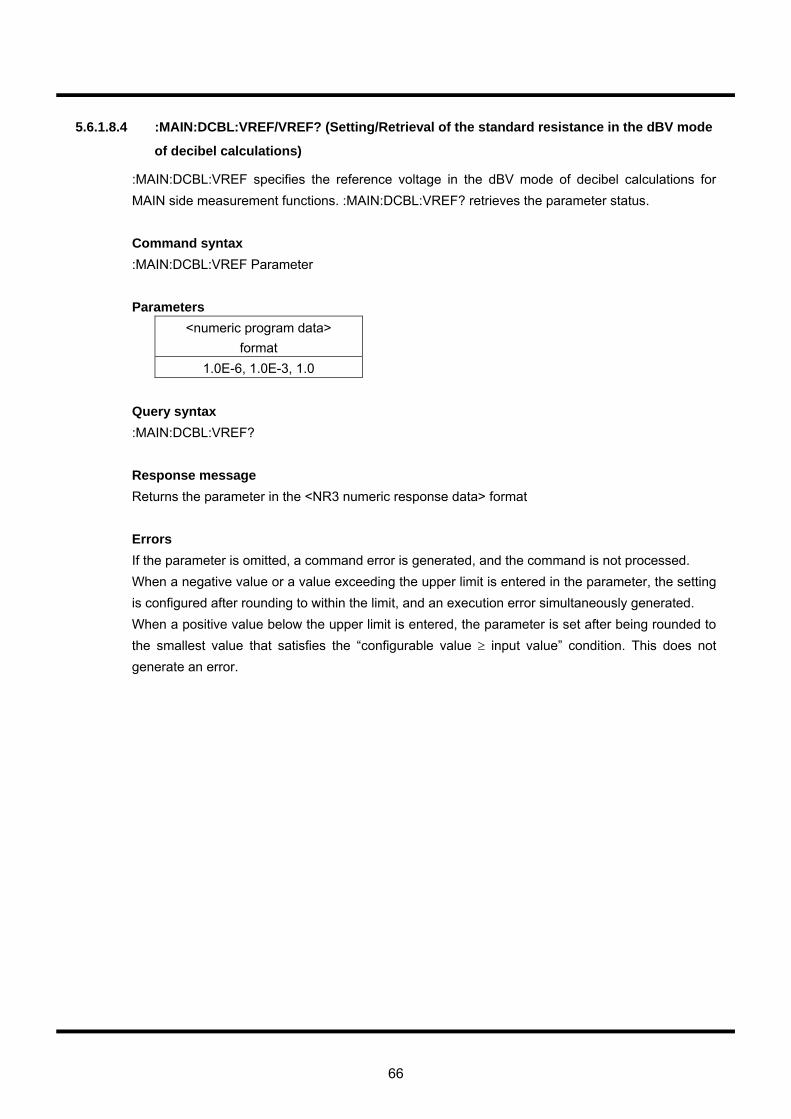
66
5.6.1.8.4 :MAIN:DCBL:VREF/VREF? (Setting/Retrieval of the standard resistance in the dBV mode
of decibel calculations)
:MAIN:DCBL:VREF specifies the reference voltage in the dBV mode of decibel calculations for MAIN side measurement functions. :MAIN:DCBL:VREF? retrieves the parameter status. Command syntax :MAIN:DCBL:VREF Parameter Parameters
<numeric program data> format
1.0E-6, 1.0E-3, 1.0 Query syntax :MAIN:DCBL:VREF? Response message Returns the parameter in the <NR3 numeric response data> format Errors If the parameter is omitted, a command error is generated, and the command is not processed. When a negative value or a value exceeding the upper limit is entered in the parameter, the setting is configured after rounding to within the limit, and an execution error simultaneously generated. When a positive value below the upper limit is entered, the parameter is set after being rounded to the smallest value that satisfies the “configurable value ≥ input value” condition. This does not generate an error.
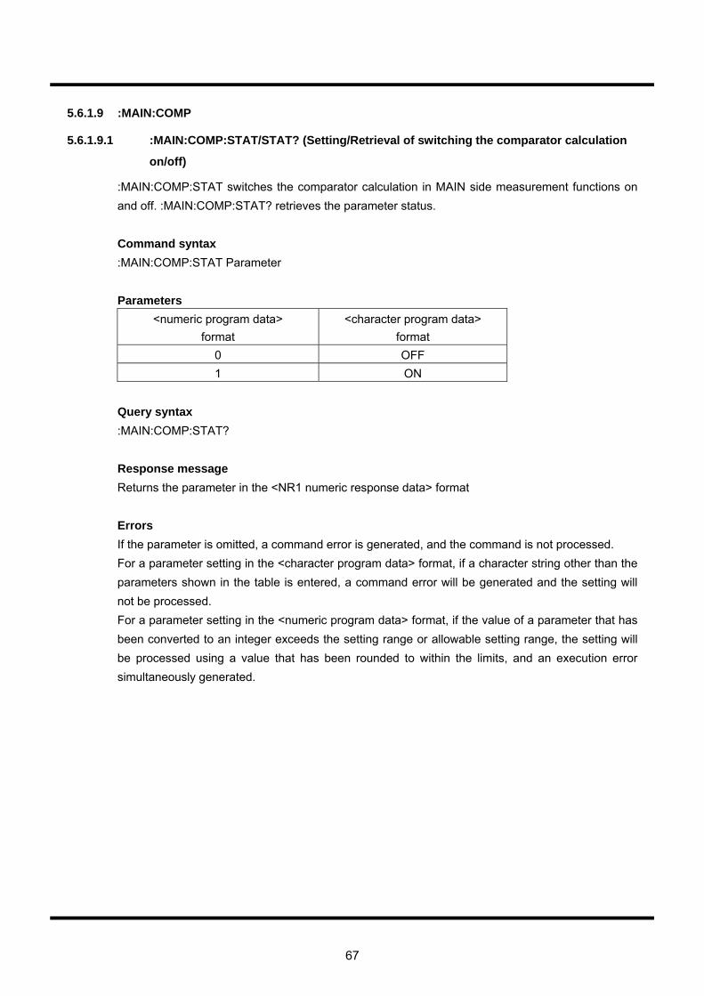
67
5.6.1.9 :MAIN:COMP
5.6.1.9.1 :MAIN:COMP:STAT/STAT? (Setting/Retrieval of switching the comparator calculation
on/off)
:MAIN:COMP:STAT switches the comparator calculation in MAIN side measurement functions on and off. :MAIN:COMP:STAT? retrieves the parameter status. Command syntax :MAIN:COMP:STAT Parameter Parameters
<numeric program data> format
<character program data> format
0 OFF 1 ON
Query syntax :MAIN:COMP:STAT? Response message Returns the parameter in the <NR1 numeric response data> format Errors If the parameter is omitted, a command error is generated, and the command is not processed. For a parameter setting in the <character program data> format, if a character string other than the parameters shown in the table is entered, a command error will be generated and the setting will not be processed. For a parameter setting in the <numeric program data> format, if the value of a parameter that has been converted to an integer exceeds the setting range or allowable setting range, the setting will be processed using a value that has been rounded to within the limits, and an execution error simultaneously generated.
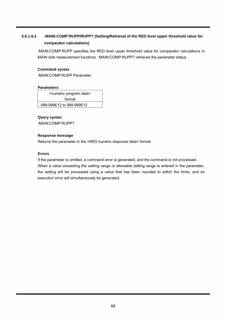
68
5.6.1.9.2 :MAIN:COMP:RUPP/RUPP? (Setting/Retrieval of the RED level upper threshold value for
comparator calculations)
:MAIN:COMP:RUPP specifies the RED level upper threshold value for comparator calculations in MAIN side measurement functions. :MAIN:COMP:RUPP? retrieves the parameter status. Command syntax :MAIN:COMP:RUPP Parameter Parameters
<numeric program data> format
-999.999E12 to 999.999E12 Query syntax :MAIN:COMP:RUPP? Response message Returns the parameter in the <NR3 numeric response data> format Errors If the parameter is omitted, a command error is generated, and the command is not processed. When a value exceeding the setting range or allowable setting range is entered in the parameter, the setting will be processed using a value that has been rounded to within the limits, and an execution error will simultaneously be generated.

69
5.6.1.9.3 :MAIN:COMP:RLOW/RLOW? (Setting/Retrieval of the RED level lower threshold value for
comparator calculations)
:MAIN:COMP:RLOW specifies the RED level lower threshold value for comparator calculations in MAIN side measurement functions. :MAIN:COMP:RLOW? retrieves the parameter status. Command syntax :MAIN:COMP:RLOW Parameter Parameters
<numeric program data> format
-999.999E12 to 999.999E12 Query syntax :MAIN:COMP:RLOW? Response message Returns the parameter in the <NR3 numeric response data> format Errors If the parameter is omitted, a command error is generated, and the command is not processed. When a value exceeding the setting range or allowable setting range is entered in the parameter, the setting will be processed using a value that has been rounded to within the limits, and an execution error will simultaneously be generated.

70
5.6.1.9.4 :MAIN:COMP:YUPP/YUPP? (Setting/Retrieval of the YELLOW level upper threshold value
for comparator calculations)
:MAIN:COMP:YUPP specifies the YELLOW level upper threshold value for comparator calculations in MAIN side measurement functions. MAIN:COMP:YUPP? retrieves the parameter status. Command syntax :MAIN:COMP:YUPP Parameter Parameters
<numeric program data> format
-999.999E12 to 999.999E12 Query syntax :MAIN:COMP:YUPP? Response message Returns the parameter in the <NR3 numeric response data> format Errors If the parameter is omitted, a command error is generated, and the command is not processed. When a value exceeding the setting range or allowable setting range is entered in the parameter, the setting will be processed using a value that has been rounded to within the limits, and an execution error will simultaneously be generated.
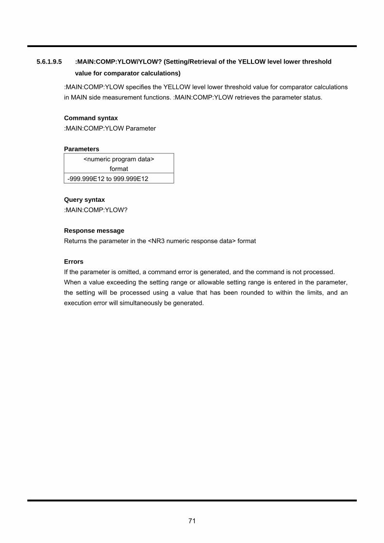
71
5.6.1.9.5 :MAIN:COMP:YLOW/YLOW? (Setting/Retrieval of the YELLOW level lower threshold
value for comparator calculations)
:MAIN:COMP:YLOW specifies the YELLOW level lower threshold value for comparator calculations in MAIN side measurement functions. :MAIN:COMP:YLOW retrieves the parameter status. Command syntax :MAIN:COMP:YLOW Parameter Parameters
<numeric program data> format
-999.999E12 to 999.999E12 Query syntax :MAIN:COMP:YLOW? Response message Returns the parameter in the <NR3 numeric response data> format Errors If the parameter is omitted, a command error is generated, and the command is not processed. When a value exceeding the setting range or allowable setting range is entered in the parameter, the setting will be processed using a value that has been rounded to within the limits, and an execution error will simultaneously be generated.
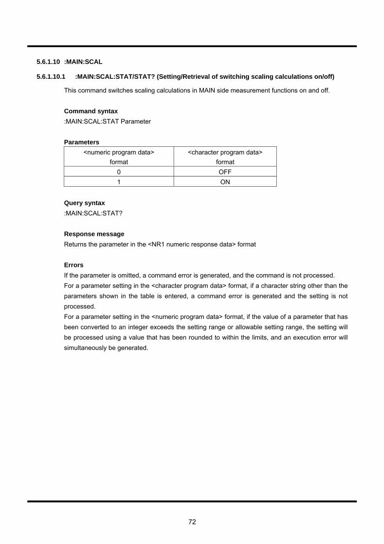
72
5.6.1.10 :MAIN:SCAL
5.6.1.10.1 :MAIN:SCAL:STAT/STAT? (Setting/Retrieval of switching scaling calculations on/off)
This command switches scaling calculations in MAIN side measurement functions on and off. Command syntax :MAIN:SCAL:STAT Parameter Parameters
<numeric program data> format
<character program data> format
0 OFF 1 ON
Query syntax :MAIN:SCAL:STAT? Response message Returns the parameter in the <NR1 numeric response data> format Errors If the parameter is omitted, a command error is generated, and the command is not processed. For a parameter setting in the <character program data> format, if a character string other than the parameters shown in the table is entered, a command error is generated and the setting is not processed. For a parameter setting in the <numeric program data> format, if the value of a parameter that has been converted to an integer exceeds the setting range or allowable setting range, the setting will be processed using a value that has been rounded to within the limits, and an execution error will simultaneously be generated.
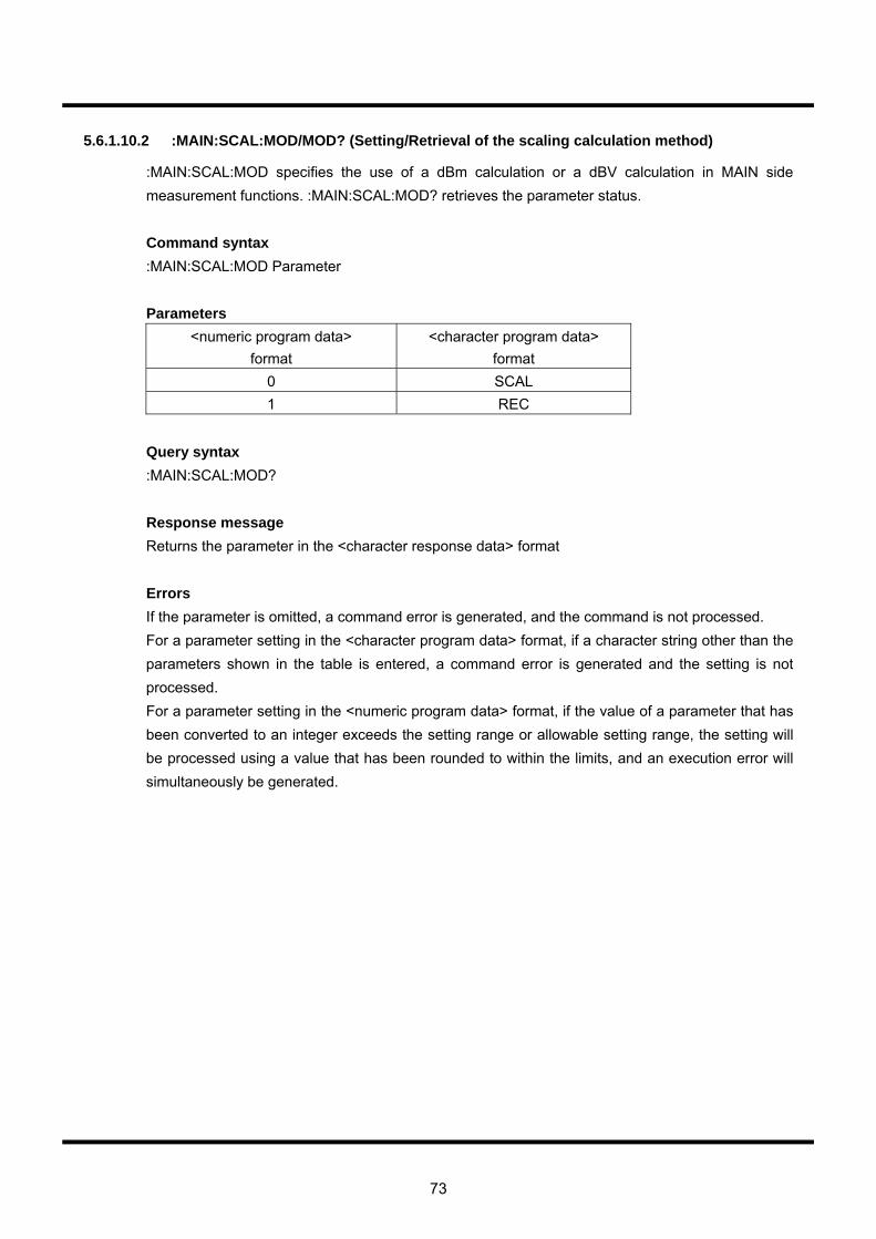
73
5.6.1.10.2 :MAIN:SCAL:MOD/MOD? (Setting/Retrieval of the scaling calculation method)
:MAIN:SCAL:MOD specifies the use of a dBm calculation or a dBV calculation in MAIN side measurement functions. :MAIN:SCAL:MOD? retrieves the parameter status. Command syntax :MAIN:SCAL:MOD Parameter Parameters
<numeric program data> format
<character program data> format
0 SCAL 1 REC
Query syntax :MAIN:SCAL:MOD? Response message Returns the parameter in the <character response data> format Errors If the parameter is omitted, a command error is generated, and the command is not processed. For a parameter setting in the <character program data> format, if a character string other than the parameters shown in the table is entered, a command error is generated and the setting is not processed. For a parameter setting in the <numeric program data> format, if the value of a parameter that has been converted to an integer exceeds the setting range or allowable setting range, the setting will be processed using a value that has been rounded to within the limits, and an execution error will simultaneously be generated.
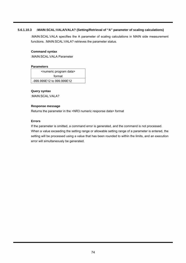
74
5.6.1.10.3 :MAIN:SCAL:VALA/VALA? (Setting/Retrieval of “A” parameter of scaling calculations)
:MAIN:SCAL:VALA specifies the A parameter of scaling calculations in MAIN side measurement functions. :MAIN:SCAL:VALA? retrieves the parameter status. Command syntax :MAIN:SCAL:VALA Parameter Parameters
<numeric program data> format
-999.999E12 to 999.999E12 Query syntax :MAIN:SCAL:VALA? Response message Returns the parameter in the <NR3 numeric response data> format Errors If the parameter is omitted, a command error is generated, and the command is not processed. When a value exceeding the setting range or allowable setting range of a parameter is entered, the setting will be processed using a value that has been rounded to within the limits, and an execution error will simultaneously be generated.

75
5.6.1.10.4 :MAIN:SCAL:VALB/VALB? (Setting/Retrieval of “B” parameter of scaling calculations)
:MAIN:SCAL:VALB specifies the B parameter of scaling calculations in MAIN side measurement functions. :MAIN:SCAL:VALB? retrieves the parameter status. Command syntax :MAIN:SCAL:VALB Parameter Parameters
<numeric program data> format
-999.999E12 to 999.999E12 Query syntax :MAIN:SCAL:VALB? Response message Returns the parameter in the <NR3 numeric response data> format Errors If the parameter is omitted, a command error is generated, and the command is not processed. When a value exceeding the setting range or allowable setting range of a parameter is entered, the setting will be processed using a value that has been rounded to within the limits, and an execution error will simultaneously be generated.

76
5.6.1.10.5 :MAIN:SCAL:VALC/VALC? (Setting/Retrieval of “C” parameter of scaling calculations)
:MAIN:SCAL:VALC specifies the C parameter of scaling calculations in MAIN side measurement functions. :MAIN:SCAL:VALC? retrieves the parameter status. Command syntax :MAIN:SCAL:VALC Parameter Parameters
<numeric program data> format
-999.999E12 to 999.999E12 Query syntax :MAIN:SCAL:VALC? Response message Returns the parameter in the <NR3 numeric response data> format Errors If the parameter is omitted, a command error is generated, and the command is not processed. When a value exceeding the setting range or allowable setting range of a parameter is entered, the setting will be processed using a value that has been rounded to within the limits, and an execution error will simultaneously be generated.

77
5.6.1.10.6 :MAIN:SCAL:VALD/VALD? (Setting/Retrieval of “D” parameter of scaling calculations)
:MAIN:SCAL:VALD specifies the D parameter of scaling calculations in MAIN side measurement functions. :MAIN:SCAL:VALD? retrieves the parameter status. Command syntax :MAIN:SCAL:VALD Parameter Parameters
<numeric program data> format
-999.999E12 to 999.999E12 Query syntax :MAIN:SCAL:VALD? Response message Returns the parameter in the <NR3 numeric response data> format Errors If the parameter is omitted, a command error is generated, and the command is not processed. When a value exceeding the setting range or allowable setting range of a parameter is entered, the setting will be processed using a value that has been rounded to within the limits, and an execution error will simultaneously be generated.
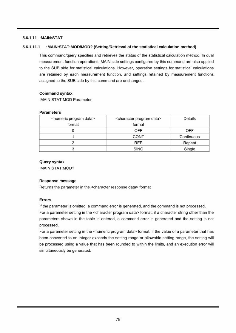
78
5.6.1.11 :MAIN:STAT
5.6.1.11.1 :MAIN:STAT:MOD/MOD? (Setting/Retrieval of the statistical calculation method)
This command/query specifies and retrieves the status of the statistical calculation method. In dual measurement function operations, MAIN side settings configured by this command are also applied to the SUB side for statistical calculations. However, operation settings for statistical calculations are retained by each measurement function, and settings retained by measurement functions assigned to the SUB side by this command are unchanged. Command syntax :MAIN:STAT:MOD Parameter Parameters
<numeric program data> format
<character program data> format
Details
0 OFF OFF 1 CONT Continuous 2 REP Repeat 3 SING Single
Query syntax :MAIN:STAT:MOD? Response message Returns the parameter in the <character response data> format Errors If the parameter is omitted, a command error is generated, and the command is not processed. For a parameter setting in the <character program data> format, if a character string other than the parameters shown in the table is entered, a command error is generated and the setting is not processed. For a parameter setting in the <numeric program data> format, if the value of a parameter that has been converted to an integer exceeds the setting range or allowable setting range, the setting will be processed using a value that has been rounded to within the limits, and an execution error will simultaneously be generated.
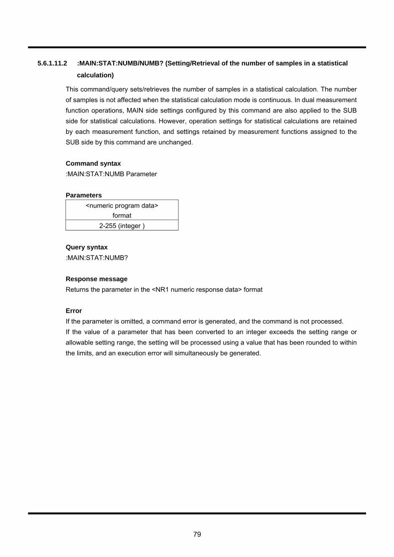
79
5.6.1.11.2 :MAIN:STAT:NUMB/NUMB? (Setting/Retrieval of the number of samples in a statistical
calculation)
This command/query sets/retrieves the number of samples in a statistical calculation. The number of samples is not affected when the statistical calculation mode is continuous. In dual measurement function operations, MAIN side settings configured by this command are also applied to the SUB side for statistical calculations. However, operation settings for statistical calculations are retained by each measurement function, and settings retained by measurement functions assigned to the SUB side by this command are unchanged. Command syntax :MAIN:STAT:NUMB Parameter Parameters
<numeric program data> format
2-255 (integer ) Query syntax :MAIN:STAT:NUMB? Response message Returns the parameter in the <NR1 numeric response data> format Error If the parameter is omitted, a command error is generated, and the command is not processed. If the value of a parameter that has been converted to an integer exceeds the setting range or allowable setting range, the setting will be processed using a value that has been rounded to within the limits, and an execution error will simultaneously be generated.
80
5.6.1.11.3 :MAIN:STAT:INIT (Initialization of the results of statistical calculations)
This command initializes past sampling results of statistical calculations. In dual measurement function operations, it also simultaneously initializes past SUB side sampling results. Command syntax :MAIN:STAT:INIT
81
5.6.2 SUB related commands
All commands with MAIN in the parent command hierarchy can be converted to SUB commands. When the dual measurement function operation is off, this simply changes the settings of the measurement function assigned by the SUB side. In addition, the command operation differs as follows compared to a MAIN command. ・ :SUB:STAT:MOD/MOD?
Since statistical calculations in dual measurement function operations comply with measurement function settings assigned by the MAIN side, the above command does not affect operations. When using measurement functions assigned by the SUB side in MAIN side single measurement functions or dual measurement functions, this new setting is used.
・ :SUB:STAT:NUMB/NUMB? is equivalent to :SUB:STAT:MOD/MOD? ・ :SUB:STAT:INIT
If this command is received during a dual measurement function operation, statistical calculations for both MAIN and SUB are initialized. This is identical to :MAIN:STAT:INIT.
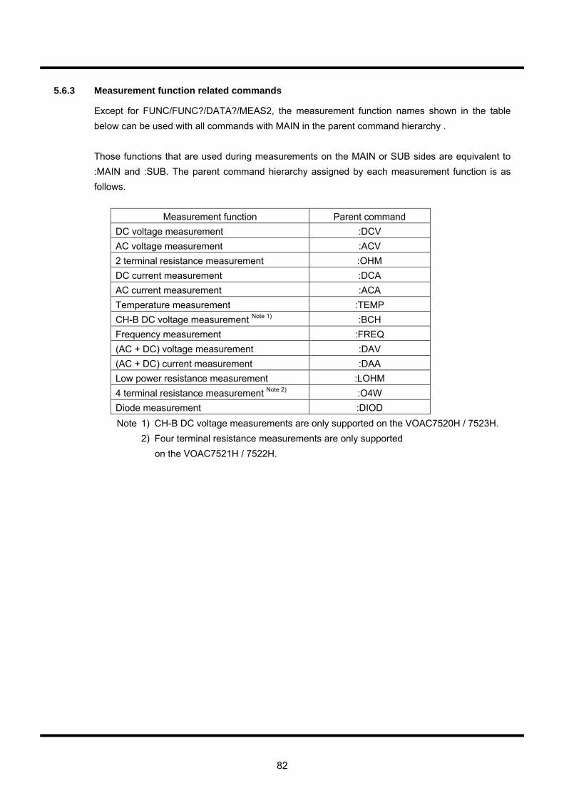
82
5.6.3 Measurement function related commands
Except for FUNC/FUNC?/DATA?/MEAS2, the measurement function names shown in the table below can be used with all commands with MAIN in the parent command hierarchy . Those functions that are used during measurements on the MAIN or SUB sides are equivalent to :MAIN and :SUB. The parent command hierarchy assigned by each measurement function is as follows.
Measurement function Parent command DC voltage measurement :DCV AC voltage measurement :ACV 2 terminal resistance measurement :OHM DC current measurement :DCA AC current measurement :ACA Temperature measurement :TEMP CH-B DC voltage measurement Note 1) :BCH Frequency measurement :FREQ (AC + DC) voltage measurement :DAV (AC + DC) current measurement :DAA Low power resistance measurement :LOHM 4 terminal resistance measurement Note 2) :O4W Diode measurement :DIOD Note 1) CH-B DC voltage measurements are only supported on the VOAC7520H / 7523H. 2) Four terminal resistance measurements are only supported on the VOAC7521H / 7522H.

83
5.6.4 Sampling related commands
5.6.4.1 :SMPL:MOD/MOD? (Selection of the sampling method)
This command is used to select the hold or free run sampling method. Command syntax :SMPL:MOD Parameter Parameters
<numeric program data> format
<character program data> format
0 FREE 1 HOLD
Query syntax :SMPL:MOD? Response message Returns the parameter in the <NR1 numeric response data> format Errors If the parameter is omitted, a command error is generated, and the command is not processed. For a parameter setting in the <character program data> format, if a character string other than the parameters shown in the table is entered, a command error is generated and the setting is not processed. For a parameter setting in the <numeric program data> format, if the value of a parameter that has been converted to an integer exceeds the setting range or allowable setting range, the setting will be processed using a value that has been rounded to within the limits, and an execution error will simultaneously be generated.
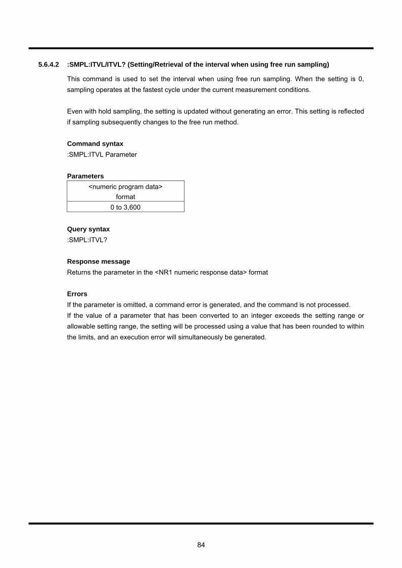
84
5.6.4.2 :SMPL:ITVL/ITVL? (Setting/Retrieval of the interval when using free run sampling)
This command is used to set the interval when using free run sampling. When the setting is 0, sampling operates at the fastest cycle under the current measurement conditions. Even with hold sampling, the setting is updated without generating an error. This setting is reflected if sampling subsequently changes to the free run method. Command syntax :SMPL:ITVL Parameter Parameters
<numeric program data> format
0 to 3,600 Query syntax :SMPL:ITVL? Response message Returns the parameter in the <NR1 numeric response data> format Errors If the parameter is omitted, a command error is generated, and the command is not processed. If the value of a parameter that has been converted to an integer exceeds the setting range or allowable setting range, the setting will be processed using a value that has been rounded to within the limits, and an execution error will simultaneously be generated.
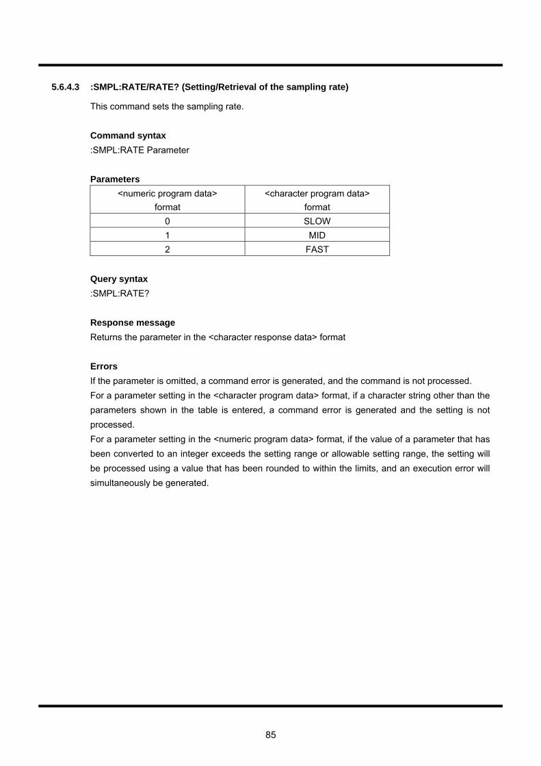
85
5.6.4.3 :SMPL:RATE/RATE? (Setting/Retrieval of the sampling rate)
This command sets the sampling rate. Command syntax :SMPL:RATE Parameter Parameters
<numeric program data> format
<character program data> format
0 SLOW 1 MID 2 FAST
Query syntax :SMPL:RATE? Response message Returns the parameter in the <character response data> format Errors If the parameter is omitted, a command error is generated, and the command is not processed. For a parameter setting in the <character program data> format, if a character string other than the parameters shown in the table is entered, a command error is generated and the setting is not processed. For a parameter setting in the <numeric program data> format, if the value of a parameter that has been converted to an integer exceeds the setting range or allowable setting range, the setting will be processed using a value that has been rounded to within the limits, and an execution error will simultaneously be generated.

86
5.6.5 Dual display related commands
5.6.5.1 :DUAL:DATA? (The simultaneous retrieval of the latest measurement results for both MAIN
and SUB)
This query simultaneously obtains the latest measurement results for both MAIN and SUB during a dual measurement function operation. If a data query is reissued without sampling after obtaining the measurement value using the previous data query, the previous value is returned. Query syntax :DUAL:DATA? Parameter Parameters
<numeric program data> format
<character program data> format
0 XNOW 1 MAX 2 MIN 3 AVER 4 SIG
Response message See “Response messages for measurement results” in Section 5.7. Errors See “Response messages for measurement results” in Section 5.7.

87
5.6.5.2 :DUAL:MEAS? (The simultaneous retrieval of the measurement results corresponding to the
trigger for both MAIN and SUB)
If the :DUAL:MEAS? query occurs during a hold, a trigger is applied, and the query simultaneously retrieves the measurement result in MAIN and SUB corresponding with the trigger. During a free run operation, a trigger does not occur, and the measurement result is retrieved immediately after. (For example, in a 10-second free run operation, if this query is issued three seconds after a trigger, there will be no response for seven seconds until the next trigger occurs.) Query syntax :DUAL:MEAS? Parameter Parameters
<numeric program data> format
<character program data> format
0 XNOW 1 MAX 2 MIN 3 AVER 4 SIG
Response message See “Response messages for measurement results” in Section 5.7. Errors See “Response messages for measurement results” in Section 5.7.
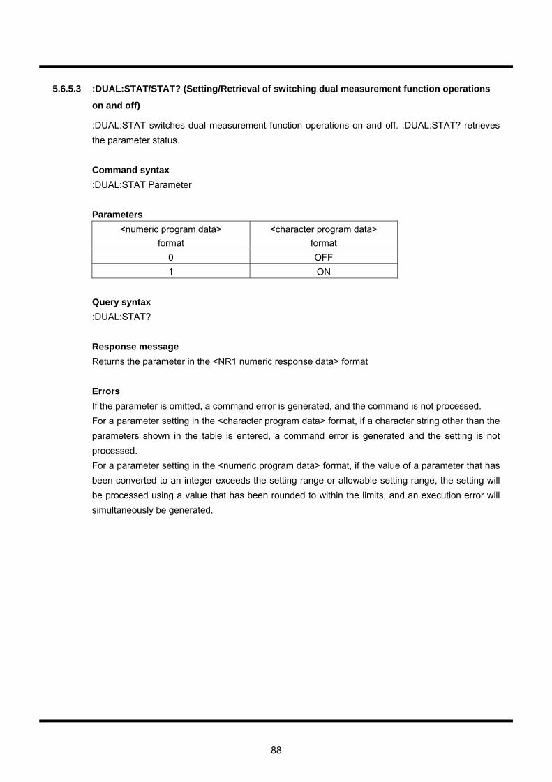
88
5.6.5.3 :DUAL:STAT/STAT? (Setting/Retrieval of switching dual measurement function operations
on and off)
:DUAL:STAT switches dual measurement function operations on and off. :DUAL:STAT? retrieves the parameter status. Command syntax :DUAL:STAT Parameter Parameters
<numeric program data> format
<character program data> format
0 OFF 1 ON
Query syntax :DUAL:STAT? Response message Returns the parameter in the <NR1 numeric response data> format Errors If the parameter is omitted, a command error is generated, and the command is not processed. For a parameter setting in the <character program data> format, if a character string other than the parameters shown in the table is entered, a command error is generated and the setting is not processed. For a parameter setting in the <numeric program data> format, if the value of a parameter that has been converted to an integer exceeds the setting range or allowable setting range, the setting will be processed using a value that has been rounded to within the limits, and an execution error will simultaneously be generated.
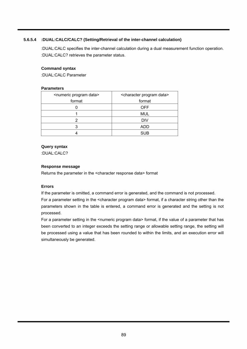
89
5.6.5.4 :DUAL:CALC/CALC? (Setting/Retrieval of the inter-channel calculation)
:DUAL:CALC specifies the inter-channel calculation during a dual measurement function operation. :DUAL:CALC? retrieves the parameter status. Command syntax :DUAL:CALC Parameter Parameters
<numeric program data> format
<character program data> format
0 OFF 1 MUL 2 DIV 3 ADD 4 SUB
Query syntax :DUAL:CALC? Response message Returns the parameter in the <character response data> format Errors If the parameter is omitted, a command error is generated, and the command is not processed. For a parameter setting in the <character program data> format, if a character string other than the parameters shown in the table is entered, a command error is generated and the setting is not processed. For a parameter setting in the <numeric program data> format, if the value of a parameter that has been converted to an integer exceeds the setting range or allowable setting range, the setting will be processed using a value that has been rounded to within the limits, and an execution error will simultaneously be generated.
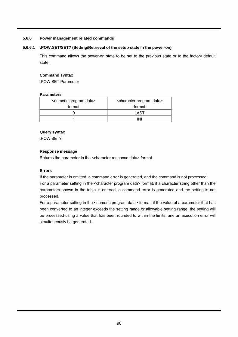
90
5.6.6 Power management related commands
5.6.6.1 :POW:SET/SET? (Setting/Retrieval of the setup state in the power-on)
This command allows the power-on state to be set to the previous state or to the factory default state. Command syntax :POW:SET Parameter Parameters
<numeric program data> format
<character program data> format
0 LAST 1 INI
Query syntax :POW:SET? Response message Returns the parameter in the <character response data> format Errors If the parameter is omitted, a command error is generated, and the command is not processed. For a parameter setting in the <character program data> format, if a character string other than the parameters shown in the table is entered, a command error is generated and the setting is not processed. For a parameter setting in the <numeric program data> format, if the value of a parameter that has been converted to an integer exceeds the setting range or allowable setting range, the setting will be processed using a value that has been rounded to within the limits, and an execution error will simultaneously be generated.
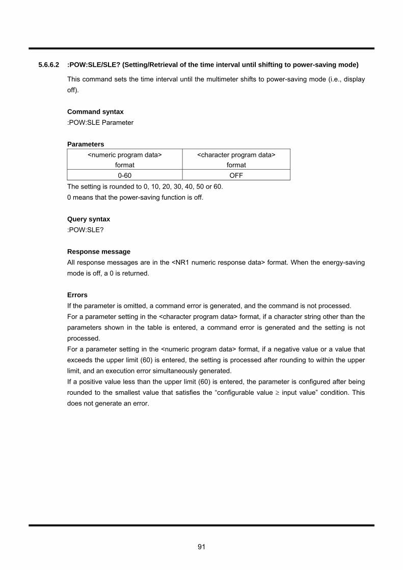
91
5.6.6.2 :POW:SLE/SLE? (Setting/Retrieval of the time interval until shifting to power-saving mode)
This command sets the time interval until the multimeter shifts to power-saving mode (i.e., display off). Command syntax :POW:SLE Parameter Parameters
<numeric program data> format
<character program data> format
0-60 OFF The setting is rounded to 0, 10, 20, 30, 40, 50 or 60. 0 means that the power-saving function is off. Query syntax :POW:SLE? Response message All response messages are in the <NR1 numeric response data> format. When the energy-saving mode is off, a 0 is returned. Errors If the parameter is omitted, a command error is generated, and the command is not processed. For a parameter setting in the <character program data> format, if a character string other than the parameters shown in the table is entered, a command error is generated and the setting is not processed. For a parameter setting in the <numeric program data> format, if a negative value or a value that exceeds the upper limit (60) is entered, the setting is processed after rounding to within the upper limit, and an execution error simultaneously generated. If a positive value less than the upper limit (60) is entered, the parameter is configured after being rounded to the smallest value that satisfies the “configurable value ≥ input value” condition. This does not generate an error.
92
5.6.6.3 :POW:SIMM (Immediate shift to power-saving mode)
This command immediately switches the multimeter to power-saving mode (i.e., display off). Command syntax :POW:SIMM
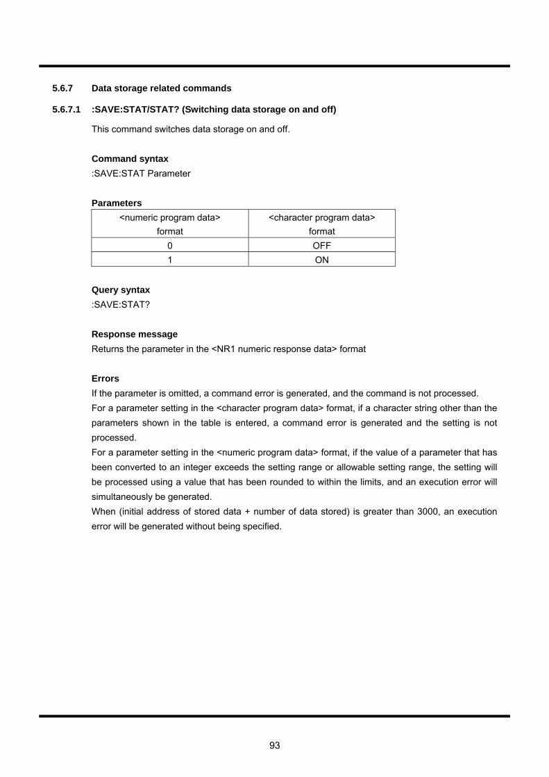
93
5.6.7 Data storage related commands
5.6.7.1 :SAVE:STAT/STAT? (Switching data storage on and off)
This command switches data storage on and off. Command syntax :SAVE:STAT Parameter Parameters
<numeric program data> format
<character program data> format
0 OFF 1 ON
Query syntax :SAVE:STAT? Response message Returns the parameter in the <NR1 numeric response data> format Errors If the parameter is omitted, a command error is generated, and the command is not processed. For a parameter setting in the <character program data> format, if a character string other than the parameters shown in the table is entered, a command error is generated and the setting is not processed. For a parameter setting in the <numeric program data> format, if the value of a parameter that has been converted to an integer exceeds the setting range or allowable setting range, the setting will be processed using a value that has been rounded to within the limits, and an execution error will simultaneously be generated. When (initial address of stored data + number of data stored) is greater than 3000, an execution error will be generated without being specified.

94
5.6.7.2 :SAVE:STAR/STAR? (Setting/Retrieval of the starting address of data storage)
This command sets the starting data storage address. Command syntax :SAVE:STAR Parameter Parameters
<numeric program data> format 0-2999
Query syntax :SAVE:STAR? Response message Returns the parameter in the <NR1 numeric response data> format Errors If the parameter is omitted, a command error is generated, and the command is not processed. If the value of a parameter that has been converted to an integer exceeds the setting range or allowable setting range, the setting will be processed using a value that has been rounded to within the limits, and an execution error will simultaneously be generated.
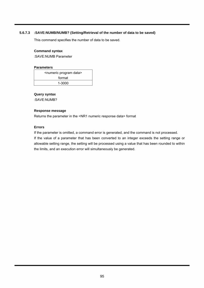
95
5.6.7.3 :SAVE:NUMB/NUMB? (Setting/Retrieval of the number of data to be saved)
This command specifies the number of data to be saved. Command syntax :SAVE:NUMB Parameter Parameters
<numeric program data> format 1-3000
Query syntax :SAVE:NUMB? Response message Returns the parameter in the <NR1 numeric response data> format Errors If the parameter is omitted, a command error is generated, and the command is not processed. If the value of a parameter that has been converted to an integer exceeds the setting range or allowable setting range, the setting will be processed using a value that has been rounded to within the limits, and an execution error will simultaneously be generated.
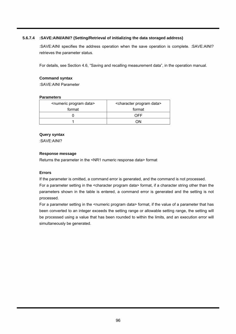
96
5.6.7.4 :SAVE:AINI/AINI? (Setting/Retrieval of initializing the data storaged address)
:SAVE:AINI specifies the address operation when the save operation is complete. :SAVE:AINI? retrieves the parameter status. For details, see Section 4.6, “Saving and recalling measurement data”, in the operation manual. Command syntax :SAVE:AINI Parameter Parameters
<numeric program data> format
<character program data> format
0 OFF 1 ON
Query syntax :SAVE:AINI? Response message Returns the parameter in the <NR1 numeric response data> format Errors If the parameter is omitted, a command error is generated, and the command is not processed. For a parameter setting in the <character program data> format, if a character string other than the parameters shown in the table is entered, a command error is generated and the setting is not processed. For a parameter setting in the <numeric program data> format, if the value of a parameter that has been converted to an integer exceeds the setting range or allowable setting range, the setting will be processed using a value that has been rounded to within the limits, and an execution error will simultaneously be generated.

97
5.6.7.5 :SAVE:TINI/TINI? (Setting/Retrieval of switching the time stamp initialization operation on
and off)
:SAVE:TINI switches the time stamp initialization operation (i.e., initialization of the time stamp 000d00h00m00.00s when a save operation commences) on and off. :SAVE:TINI? retrieves the parameter status. Command syntax :SAVE:TINI Parameter Parameters
<numeric program data> format
<character program data> format
0 OFF 1 ON
Query syntax :SAVE:TINI? Response message Returns the parameter in the <NR1 numeric response data> format Errors If the parameter is omitted, a command error is generated, and the command is not processed. For a parameter setting in the <character program data> format, if a character string other than the parameters shown in the table is entered, a command error is generated and the setting is not processed. For a parameter setting in the <numeric program data> format, if the value of a parameter that has been converted to an integer exceeds the setting range or allowable setting range, the setting will be processed using a value that has been rounded to within the limits, and an execution error will simultaneously be generated.
98
5.6.7.6 :SAVE:CLR (Initializing all of the stored data)
:SAVE:CLR clears all of the stored data. Command syntax :SAVE:CLR

99
5.6.8 Data recall related commands
5.6.8.1 :RCLL:RADR/RADR? (Setting/Retrieval of the address after retrieving stored data)
:RCLL:RADR specifies the address after retrieving stored data. Command syntax :RCLL:RADR Parameter Parameters
<numeric program data> format 0-2999
Query syntax :RCLL:RADR? Response message Returns the parameter in the <NR1 numeric response data> format Errors If the parameter is omitted, a command error is generated, and the command is not processed. If the value of a parameter that has been converted to an integer exceeds the setting range or allowable setting range, the setting will be processed using a value that has been rounded to within the limits, and an execution error will simultaneously be generated.
100
5.6.8.2 :RCLL:DATA? (Retrieval of all of stored data)
:RCLL:DATA reads stored data. Every time this command is processed, the address to be read is automatically incremented by one. After address 2999 has been read, the address to be read returns to 0000. Query :RCLL:DATA? Response message See “Response messages for measurement results” in Section 5.7.
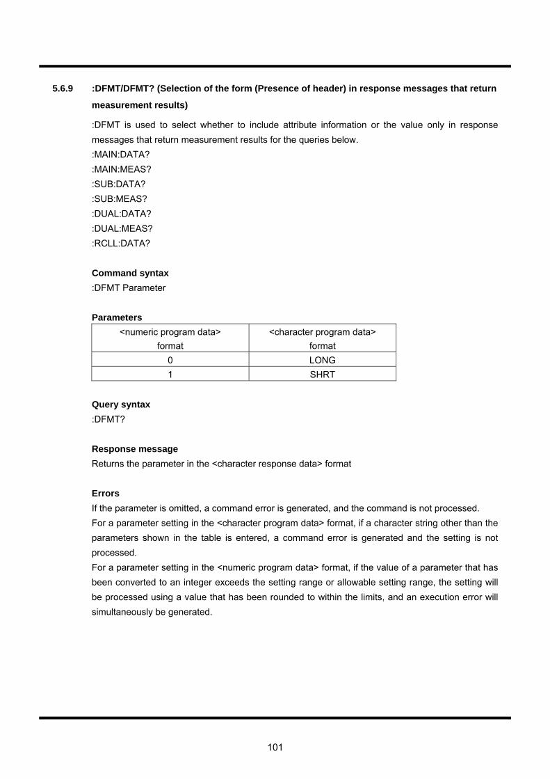
101
5.6.9 :DFMT/DFMT? (Selection of the form (Presence of header) in response messages that return
measurement results)
:DFMT is used to select whether to include attribute information or the value only in response messages that return measurement results for the queries below. :MAIN:DATA? :MAIN:MEAS? :SUB:DATA? :SUB:MEAS? :DUAL:DATA? :DUAL:MEAS? :RCLL:DATA? Command syntax :DFMT Parameter Parameters
<numeric program data> format
<character program data> format
0 LONG 1 SHRT
Query syntax :DFMT? Response message Returns the parameter in the <character response data> format Errors If the parameter is omitted, a command error is generated, and the command is not processed. For a parameter setting in the <character program data> format, if a character string other than the parameters shown in the table is entered, a command error is generated and the setting is not processed. For a parameter setting in the <numeric program data> format, if the value of a parameter that has been converted to an integer exceeds the setting range or allowable setting range, the setting will be processed using a value that has been rounded to within the limits, and an execution error will simultaneously be generated.
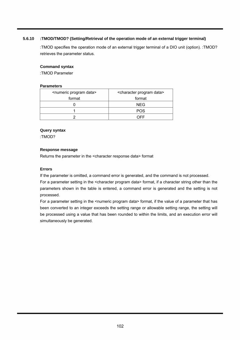
102
5.6.10 :TMOD/TMOD? (Setting/Retrieval of the operation mode of an external trigger terminal)
:TMOD specifies the operation mode of an external trigger terminal of a DIO unit (option). :TMOD? retrieves the parameter status. Command syntax :TMOD Parameter Parameters
<numeric program data> format
<character program data> format
0 NEG 1 POS 2 OFF
Query syntax :TMOD? Response message Returns the parameter in the <character response data> format Errors If the parameter is omitted, a command error is generated, and the command is not processed. For a parameter setting in the <character program data> format, if a character string other than the parameters shown in the table is entered, a command error is generated and the setting is not processed. For a parameter setting in the <numeric program data> format, if the value of a parameter that has been converted to an integer exceeds the setting range or allowable setting range, the setting will be processed using a value that has been rounded to within the limits, and an execution error will simultaneously be generated.
103
5.6.11 Time stamp related commands
5.6.11.1 :TIME:NOW? (The time that has elapsed since system startup)
:TIME:NOW? returns the time that has elapsed since system startup (or since the initialization of the time stamp) to the current moment. Query syntax :TIME:NOW? Response message The response message returns a character strings that indicates the elapsed time in the following format: 000d00h00m00.00s

104
5.6.11.2 :TIME:INIT (Initialization of the time stamp)
:TIME:INIT initializes the time stamp. (The time stamp is reset to 000d00h00m00.00s when the command is received.) Command syntax :TIME:INIT
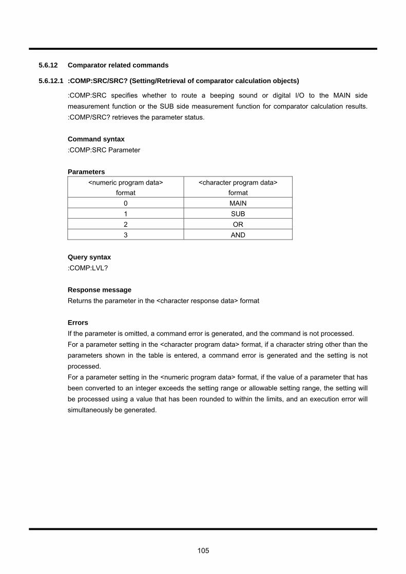
105
5.6.12 Comparator related commands
5.6.12.1 :COMP:SRC/SRC? (Setting/Retrieval of comparator calculation objects)
:COMP:SRC specifies whether to route a beeping sound or digital I/O to the MAIN side measurement function or the SUB side measurement function for comparator calculation results. :COMP/SRC? retrieves the parameter status. Command syntax :COMP:SRC Parameter Parameters
<numeric program data> format
<character program data> format
0 MAIN 1 SUB 2 OR 3 AND
Query syntax :COMP:LVL? Response message Returns the parameter in the <character response data> format Errors If the parameter is omitted, a command error is generated, and the command is not processed. For a parameter setting in the <character program data> format, if a character string other than the parameters shown in the table is entered, a command error is generated and the setting is not processed. For a parameter setting in the <numeric program data> format, if the value of a parameter that has been converted to an integer exceeds the setting range or allowable setting range, the setting will be processed using a value that has been rounded to within the limits, and an execution error will simultaneously be generated.
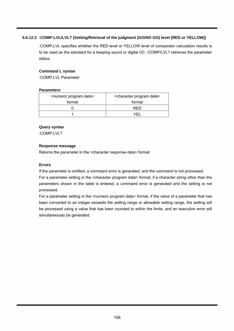
106
5.6.12.2 :COMP:LVL/LVL? (Setting/Retrieval of the judgment (GO/NO GO) level (RED or YELLOW))
:COMP:LVL specifies whether the RED level or YELLOW level of comparator calculation results is to be used as the standard for a beeping sound or digital I/O. :COMP/LVL? retrieves the parameter status. Command L syntax :COMP:LVL Parameter Parameters
<numeric program data> format
<character program data> format
0 RED 1 YEL
Query syntax :COMP:LVL? Response message Returns the parameter in the <character response data> format Errors If the parameter is omitted, a command error is generated, and the command is not processed. For a parameter setting in the <character program data> format, if a character string other than the parameters shown in the table is entered, a command error is generated and the setting is not processed. For a parameter setting in the <numeric program data> format, if the value of a parameter that has been converted to an integer exceeds the setting range or allowable setting range, the setting will be processed using a value that has been rounded to within the limits, and an execution error will simultaneously be generated.
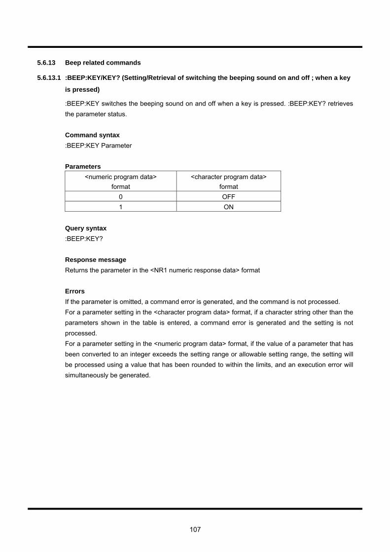
107
5.6.13 Beep related commands
5.6.13.1 :BEEP:KEY/KEY? (Setting/Retrieval of switching the beeping sound on and off ; when a key
is pressed)
:BEEP:KEY switches the beeping sound on and off when a key is pressed. :BEEP:KEY? retrieves the parameter status. Command syntax :BEEP:KEY Parameter Parameters
<numeric program data> format
<character program data> format
0 OFF 1 ON
Query syntax :BEEP:KEY? Response message Returns the parameter in the <NR1 numeric response data> format Errors If the parameter is omitted, a command error is generated, and the command is not processed. For a parameter setting in the <character program data> format, if a character string other than the parameters shown in the table is entered, a command error is generated and the setting is not processed. For a parameter setting in the <numeric program data> format, if the value of a parameter that has been converted to an integer exceeds the setting range or allowable setting range, the setting will be processed using a value that has been rounded to within the limits, and an execution error will simultaneously be generated.
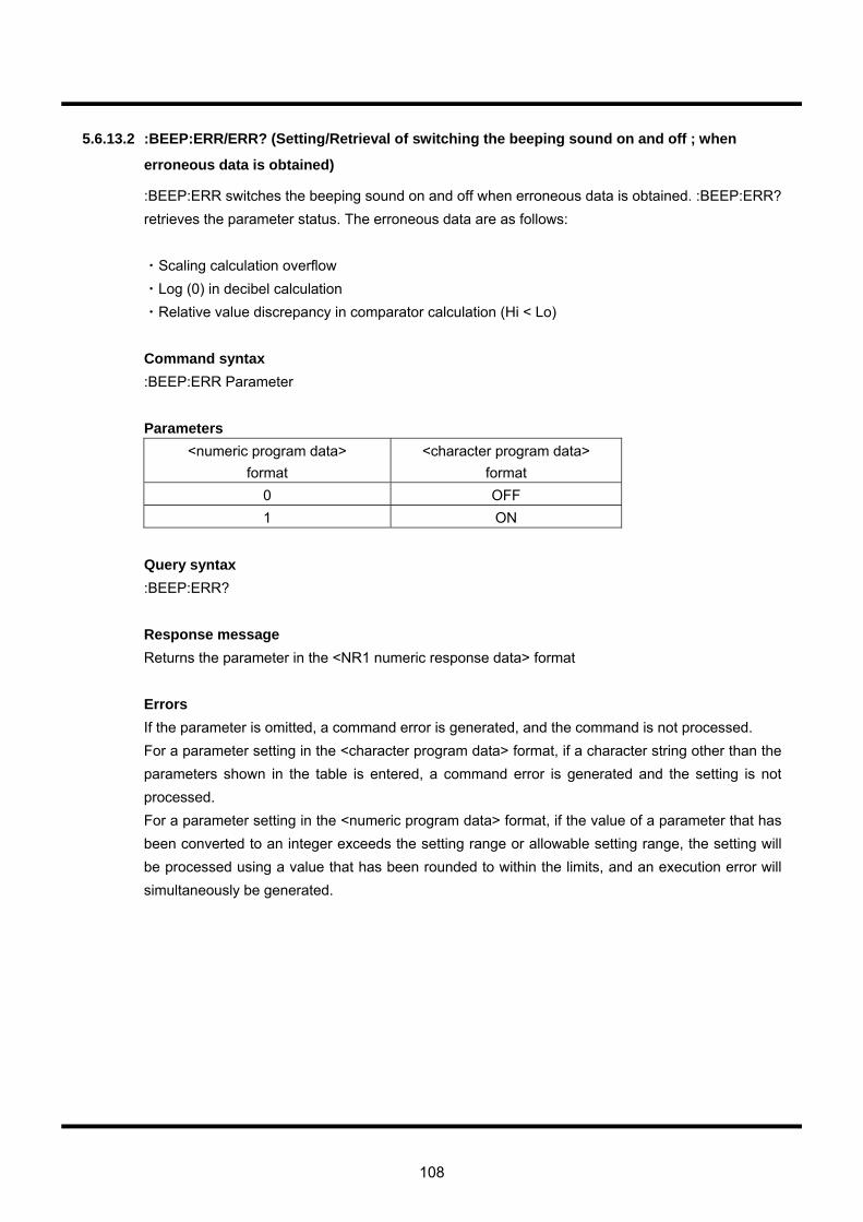
108
5.6.13.2 :BEEP:ERR/ERR? (Setting/Retrieval of switching the beeping sound on and off ; when
erroneous data is obtained)
:BEEP:ERR switches the beeping sound on and off when erroneous data is obtained. :BEEP:ERR? retrieves the parameter status. The erroneous data are as follows: ・Scaling calculation overflow ・Log (0) in decibel calculation ・Relative value discrepancy in comparator calculation (Hi < Lo) Command syntax :BEEP:ERR Parameter Parameters
<numeric program data> format
<character program data> format
0 OFF 1 ON
Query syntax :BEEP:ERR? Response message Returns the parameter in the <NR1 numeric response data> format Errors If the parameter is omitted, a command error is generated, and the command is not processed. For a parameter setting in the <character program data> format, if a character string other than the parameters shown in the table is entered, a command error is generated and the setting is not processed. For a parameter setting in the <numeric program data> format, if the value of a parameter that has been converted to an integer exceeds the setting range or allowable setting range, the setting will be processed using a value that has been rounded to within the limits, and an execution error will simultaneously be generated.
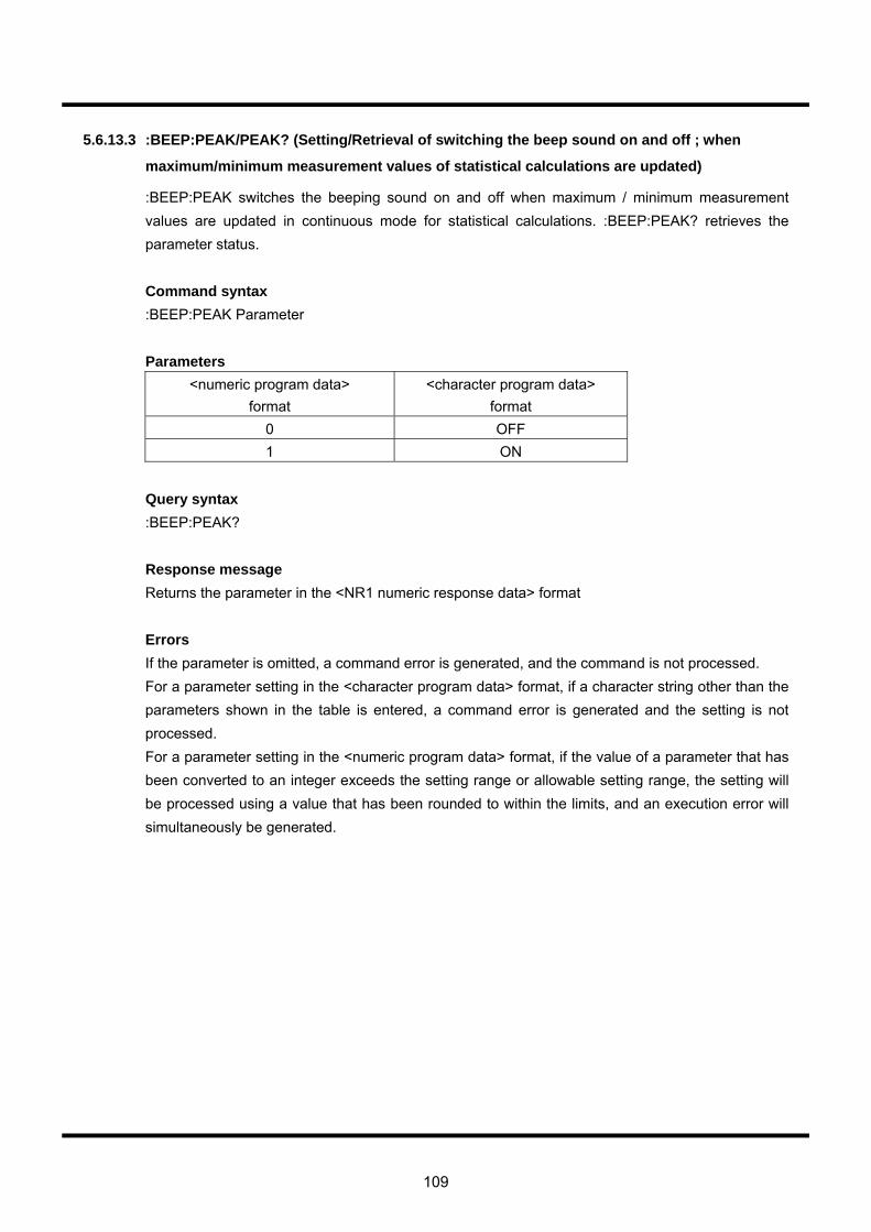
109
5.6.13.3 :BEEP:PEAK/PEAK? (Setting/Retrieval of switching the beep sound on and off ; when
maximum/minimum measurement values of statistical calculations are updated)
:BEEP:PEAK switches the beeping sound on and off when maximum / minimum measurement values are updated in continuous mode for statistical calculations. :BEEP:PEAK? retrieves the parameter status. Command syntax :BEEP:PEAK Parameter Parameters
<numeric program data> format
<character program data> format
0 OFF 1 ON
Query syntax :BEEP:PEAK? Response message Returns the parameter in the <NR1 numeric response data> format Errors If the parameter is omitted, a command error is generated, and the command is not processed. For a parameter setting in the <character program data> format, if a character string other than the parameters shown in the table is entered, a command error is generated and the setting is not processed. For a parameter setting in the <numeric program data> format, if the value of a parameter that has been converted to an integer exceeds the setting range or allowable setting range, the setting will be processed using a value that has been rounded to within the limits, and an execution error will simultaneously be generated.
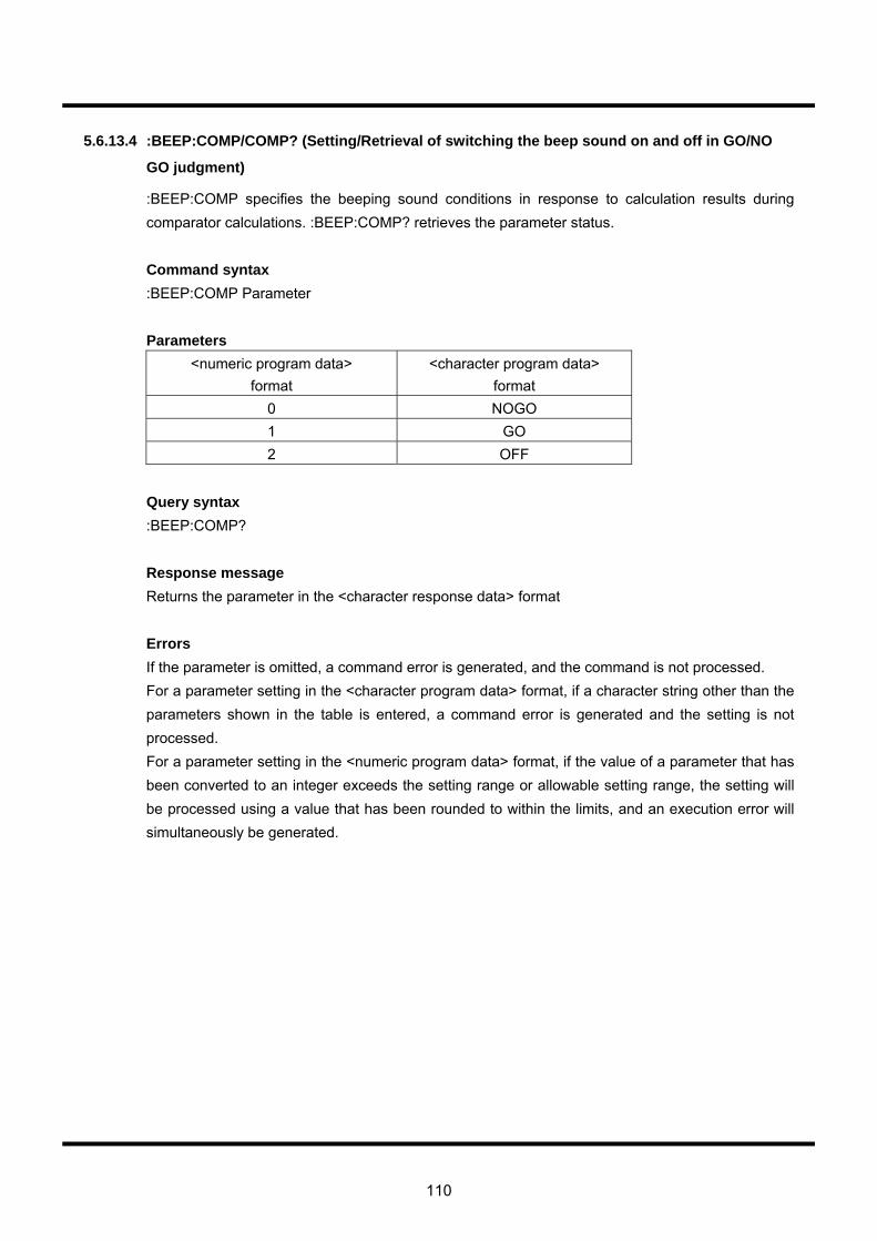
110
5.6.13.4 :BEEP:COMP/COMP? (Setting/Retrieval of switching the beep sound on and off in GO/NO
GO judgment)
:BEEP:COMP specifies the beeping sound conditions in response to calculation results during comparator calculations. :BEEP:COMP? retrieves the parameter status. Command syntax :BEEP:COMP Parameter Parameters
<numeric program data> format
<character program data> format
0 NOGO 1 GO 2 OFF
Query syntax :BEEP:COMP? Response message Returns the parameter in the <character response data> format Errors If the parameter is omitted, a command error is generated, and the command is not processed. For a parameter setting in the <character program data> format, if a character string other than the parameters shown in the table is entered, a command error is generated and the setting is not processed. For a parameter setting in the <numeric program data> format, if the value of a parameter that has been converted to an integer exceeds the setting range or allowable setting range, the setting will be processed using a value that has been rounded to within the limits, and an execution error will simultaneously be generated.
111
5.6.14 Device-specific status report related commands
5.6.14.1 DDER? (Retrieval of the device-dependent error status register)
DDER? retrieves the device-dependent error status register. Query syntax :DDER? Response message The query returns an 8-bit value for DDER (Device Dependent Error Status Register) ranging from 0-255 in the <NR1 numeric value response data> format. Refer to Section 5.2, “Status report structure” for the allocation of each bit.

112
5.6.14.2 DDEE/DDEE? (Setting/Retrieval of the device-dependent error status enable register)
DDEE configures the device-dependent error status enable register. DDEE? retrieves the parameter status. Command syntax :DDEE Parameter Parameters
numeric program data format 0-255
Query syntax :DDEE? Response message The query returns an 8-bit value for DDEE (Device Dependent Error Status Enable Register) ranging from 0-255 in the <NR1 numeric value response data> format. Refer to Section 5.2, “Status report structure” for the allocation of each bit. Errors If the parameter is omitted, a command error is generated, and the command is not processed. If the value of a parameter that has been converted to an integer exceeds the setting range or allowable setting range, the setting will be processed using a value that has been rounded to within the limits, and an execution error will simultaneously be generated.
113
5.6.14.3 MESR? (Retrieval of the measurement event status register)
MESR? retrieves the measurement event status register. Query syntax :MESR? Response message The query returns an 8-bit value for the MESR Measurement Event Status Register Device Dependent Error Status Register) ranging from 0 to 255 in the <NR1 numeric value response data> format. Refer to Section 5.2, “Status report structure” for the allocation of each bit.
114
5.6.14.4 MESE/MESE? (Retrieval of the status measurement event status enable register)
MESE configures the status measurement event status enable register. MESE? retrieves the register status. Command syntax :MESE Parameter Parameters
<numeric program data> format 0-255
Query syntax :MESE? Response message The query returns an 8-bit value for the MESE Measurement Event Status Enable register ranging from 0 to 255 in the <NR1 numeric value response data> format. Refer to Section 5.2, “Status report structure” for the allocation of each bit. Errors If the parameter is omitted, a command error is generated, and the command is not processed. If the value of a parameter that has been converted to an integer exceeds the setting range or allowable setting range, the setting will be processed using a value that has been rounded to within the limits, and an execution error will simultaneously be generated.
115
5.6.15 Option switches
5.6.15.1 :OPT:SW1/SW1? (Setting/Retrieval of switching the function that protects the
resistance-measuring circuit)
This command switches the function that protects the resistance-measuring circuit (i.e., the function that checks the voltage applied between the Ω:HI LO terminals) on and off when a resistance measurement function (2WΩ, 4WΩ, Lo-Ω and DIODE) has been selected. When ON, the applied voltage is checked. When OFF, the applied voltage is not checked. Command syntax
:OPT:SW1 Parameter Parameters
<numeric program data> format
<character program data> format
0 OFF 1 ON
Query syntax
:OPT:SW1? Response message
Parameters are returned in the <NR1 numeric response data> format. Errors
When the parameter is omitted, a command error is generated and the command is not processed. For parameter settings in the <character program data> format, when character strings other than those described in the above parameter table are input, a command error is generated and the setting is not processed. For parameter settings in the <numeric program data> format, when a parameter that has been converted to an integer exceeds the upper/lower limit, the setting will be processed using a value that has been rounded within the range, and at the same time, an execution error will be generated.
CAUTION!!
This command/query was added to version 1.20 of the software on. As a result, a command error will be generated when this command/query is sent to previous VOAC versions.
116
5.6.15.2 :OPT:SW2/SW2? (Setting/Retrieval of the AUTO range in resistance measurements)
This command adjusts the AUTO range in 2WΩ and 4WΩ measurements as shown below: ON : Sets all ranges to AUTO range, including the 500MΩ range. OFF : Sets the 50MΩ range and below to AUTO range, excluding the 500MΩ range
Command syntax
:OPT:SW2 Parameter Parameters
<numeric program data> format
<character program data> format
0 OFF 1 ON
Query syntax
:OPT:SW2? Response message
Parameters are returned in the <NR1 numeric response data> format. Errors
When the parameter is omitted, a command error is generated and the command is not processed. For parameter settings in the <character program data> format, when character strings other than those described in the above parameter table are input, a command error is generated and the setting is not processed. For parameter settings in the <numeric program data> format, when a parameter that has been converted to an integer exceeds the upper/lower limit, the setting will be processed using a value that has been rounded within the range, and at the same time, an execution error will be generated.
CAUTION!!
This command/query was added to version 1.20 of the software on. As a result, a command error will be generated when this command/query is sent to previous VOAC versions.
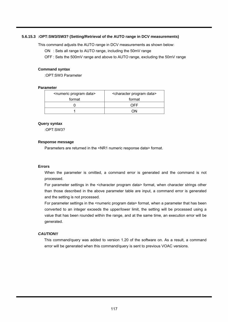
117
5.6.15.3 :OPT:SW3/SW3? (Setting/Retrieval of the AUTO range in DCV measurements)
This command adjusts the AUTO range in DCV measurements as shown below: ON : Sets all range to AUTO range, including the 50mV range OFF : Sets the 500mV range and above to AUTO range, excluding the 50mV range
Command syntax
:OPT:SW3 Parameter Parameter
<numeric program data> format
<character program data> format
0 OFF 1 ON
Query syntax
:OPT:SW3? Response message
Parameters are returned in the <NR1 numeric response data> format.
Errors
When the parameter is omitted, a command error is generated and the command is not processed. For parameter settings in the <character program data> format, when character strings other than those described in the above parameter table are input, a command error is generated and the setting is not processed. For parameter settings in the <numeric program data> format, when a parameter that has been converted to an integer exceeds the upper/lower limit, the setting will be processed using a value that has been rounded within the range, and at the same time, an execution error will be generated.
CAUTION!!
This command/query was added to version 1.20 of the software on. As a result, a command error will be generated when this command/query is sent to previous VOAC versions.
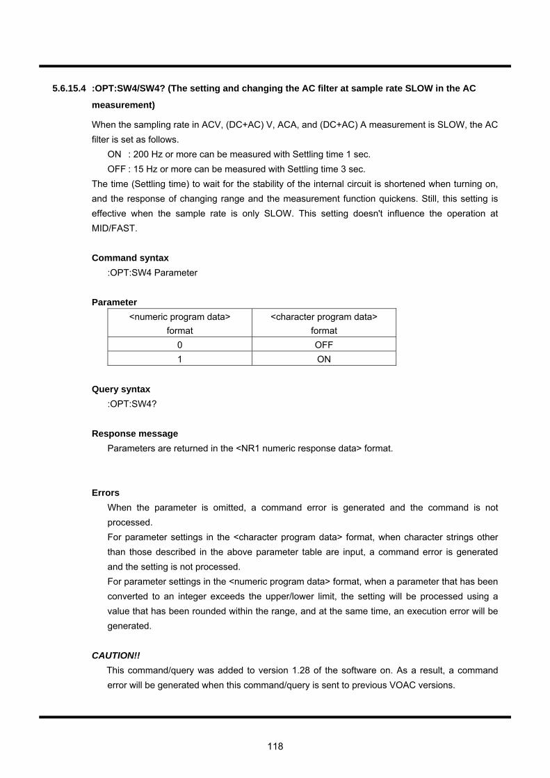
118
5.6.15.4 :OPT:SW4/SW4? (The setting and changing the AC filter at sample rate SLOW in the AC
measurement)
When the sampling rate in ACV, (DC+AC) V, ACA, and (DC+AC) A measurement is SLOW, the AC filter is set as follows.
ON : 200 Hz or more can be measured with Settling time 1 sec. OFF : 15 Hz or more can be measured with Settling time 3 sec.
The time (Settling time) to wait for the stability of the internal circuit is shortened when turning on, and the response of changing range and the measurement function quickens. Still, this setting is effective when the sample rate is only SLOW. This setting doesn't influence the operation at MID/FAST. Command syntax
:OPT:SW4 Parameter Parameter
<numeric program data> format
<character program data> format
0 OFF 1 ON
Query syntax
:OPT:SW4? Response message
Parameters are returned in the <NR1 numeric response data> format.
Errors
When the parameter is omitted, a command error is generated and the command is not processed. For parameter settings in the <character program data> format, when character strings other than those described in the above parameter table are input, a command error is generated and the setting is not processed. For parameter settings in the <numeric program data> format, when a parameter that has been converted to an integer exceeds the upper/lower limit, the setting will be processed using a value that has been rounded within the range, and at the same time, an execution error will be generated.
CAUTION!!
This command/query was added to version 1.28 of the software on. As a result, a command error will be generated when this command/query is sent to previous VOAC versions.
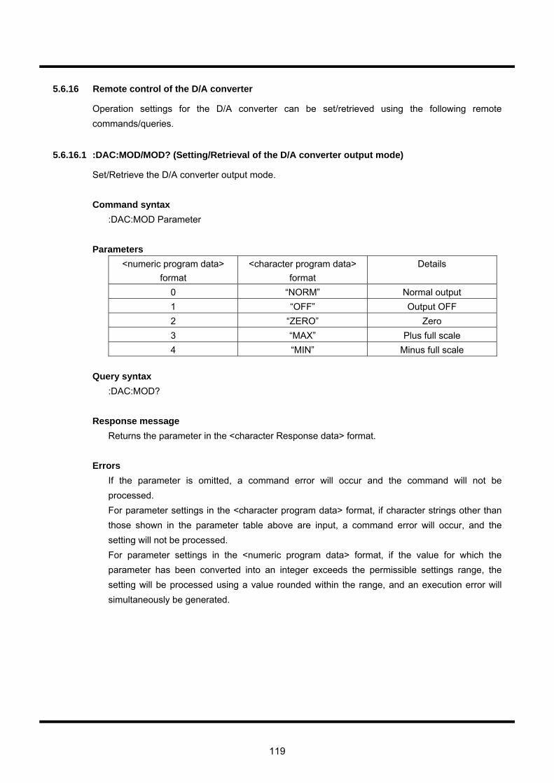
119
5.6.16 Remote control of the D/A converter
Operation settings for the D/A converter can be set/retrieved using the following remote commands/queries.
5.6.16.1 :DAC:MOD/MOD? (Setting/Retrieval of the D/A converter output mode)
Set/Retrieve the D/A converter output mode. Command syntax
:DAC:MOD Parameter
Parameters <numeric program data>
format <character program data>
format Details
0 “NORM” Normal output 1 “OFF” Output OFF 2 “ZERO” Zero 3 “MAX” Plus full scale 4 “MIN” Minus full scale
Query syntax
:DAC:MOD?
Response message Returns the parameter in the <character Response data> format.
Errors If the parameter is omitted, a command error will occur and the command will not be processed. For parameter settings in the <character program data> format, if character strings other than those shown in the parameter table above are input, a command error will occur, and the setting will not be processed. For parameter settings in the <numeric program data> format, if the value for which the parameter has been converted into an integer exceeds the permissible settings range, the setting will be processed using a value rounded within the range, and an execution error will simultaneously be generated.
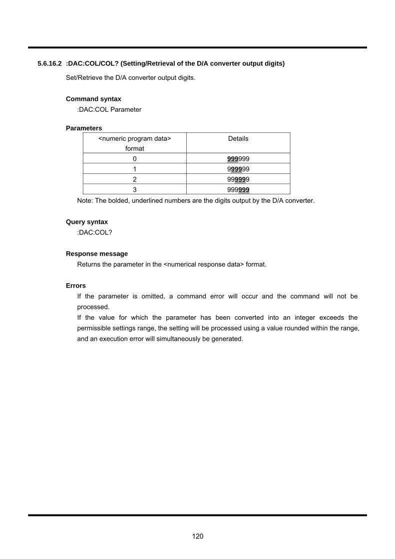
120
5.6.16.2 :DAC:COL/COL? (Setting/Retrieval of the D/A converter output digits)
Set/Retrieve the D/A converter output digits. Command syntax
:DAC:COL Parameter
Parameters <numeric program data>
format Details
0 999999 1 999999 2 999999 3 999999
Note: The bolded, underlined numbers are the digits output by the D/A converter.
Query syntax :DAC:COL?
Response message Returns the parameter in the <numerical response data> format.
Errors If the parameter is omitted, a command error will occur and the command will not be processed. If the value for which the parameter has been converted into an integer exceeds the permissible settings range, the setting will be processed using a value rounded within the range, and an execution error will simultaneously be generated.
121
5.7 Response messages for measurement results This section explains the definitions and character restrictions with regard to response messages for measurement results in remote control mode. The following seven types of queries return measurement results in remote control mode: 1. :MAIN:DATA? 2. :MAIN:MEAS? 3. :SUB:DATA? 4. :SUB:MEAS? 5. :DUAL:DATA? 6. :DUAL:MEAS? 7. :RCLL:DATA? There are two types of response messages for measurement results: The long form, in which conditions recorded during measurements are added to the measurement value, and the short form, which consists of the value only. Selecting which of these types to return is done through the :DFMT command. Since the above queries beginning with :DUAL (5 and 6) simultaneously obtain MAIN and SUB measurement results during dual measurement function operations, the form of other query and response messages is different. There are four possible response forms due to differences in long/short and single/dual.
5.7.1 Field definitions
The response messages for measurement results consist of multiple fields separated by commas. The following types of fields exist.
5.7.1.1 Function information field (Func)
Func indicates the measurement function and has a fixed length of four characters. The character string definitions are shown in the table on the following page.
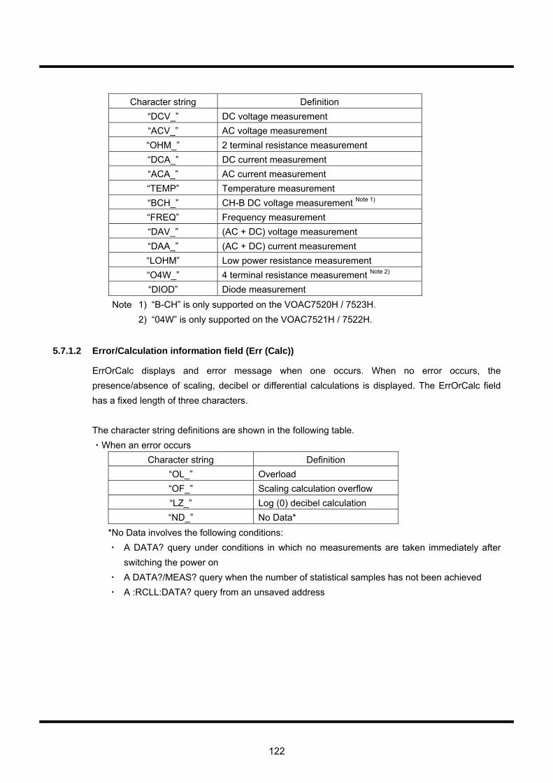
122
Character string Definition
“DCV_” DC voltage measurement “ACV_” AC voltage measurement “OHM_” 2 terminal resistance measurement “DCA_” DC current measurement “ACA_” AC current measurement “TEMP” Temperature measurement “BCH_” CH-B DC voltage measurement Note 1) “FREQ” Frequency measurement “DAV_” (AC + DC) voltage measurement “DAA_” (AC + DC) current measurement “LOHM” Low power resistance measurement “O4W_” 4 terminal resistance measurement Note 2) “DIOD” Diode measurement
Note 1) “B-CH” is only supported on the VOAC7520H / 7523H. 2) “04W” is only supported on the VOAC7521H / 7522H.
5.7.1.2 Error/Calculation information field (Err (Calc))
ErrOrCalc displays and error message when one occurs. When no error occurs, the presence/absence of scaling, decibel or differential calculations is displayed. The ErrOrCalc field has a fixed length of three characters. The character string definitions are shown in the following table. ・When an error occurs
Character string Definition “OL_” Overload “OF_” Scaling calculation overflow “LZ_” Log (0) decibel calculation “ND_” No Data*
*No Data involves the following conditions: ・ A DATA? query under conditions in which no measurements are taken immediately after
switching the power on ・ A DATA?/MEAS? query when the number of statistical samples has not been achieved ・ A :RCLL:DATA? query from an unsaved address

123
・When no error occurs Character string Scaling calculation Decibel
calculation Differential calculation
“_ _ _” OFF OFF OFF “S_ _” ON OFF OFF “_D_” OFF ON OFF “SD_” ON ON OFF “_ _R” OFF OFF ON “S_R” ON OFF ON “_DR” OFF ON ON “SDR” ON ON ON
5.7.1.3 Type of statistical data field (Type)
This field displays the type of raw data or statistical calculation result, and has a fixed length of three characters. The character string definitions are as follows:
Character string Definition “_ _ _” Raw data “MAX” Maximum value “MIN” Minimum value “AVG” Moving average value “SIG” Standard deviation, σ
5.7.1.4 Measurement value field (Value)
This field displays the measurement value itself and can be up to 12 characters long. The components of this field are as follows: ・ Sign: the sign cannot be omitted even for positive values ・ Mantissa: (valid number of digits+1) numeric character string ・ Exponent: displayed as E plus an exponent number consisting of two or three characters
(including the sign). The exponent sign cannot be omitted even for positive values. The exponent number always consists of integral multiples of three.
5.7.1.5 Time stamp field (TimeStamp)
This field shows the time that has elapsed since turning the multimeter on, and consists of a maximum of ten positive integers. One count is equivalent to 10 milliseconds. This value is converted into day, hour, minutes and seconds according to the simple expressions below.
Unit Conversion expression Day Time stamp count/8640000 Hour (Time stamp count/360000) % 24
Minutes (Time stamp count/6000) % 60 Seconds (Time stamp count/100) % 60
Milliseconds (Time stamp count % 100) * 10 Note: The “a%b” in the conversion expression indicates the remainder of a/b.
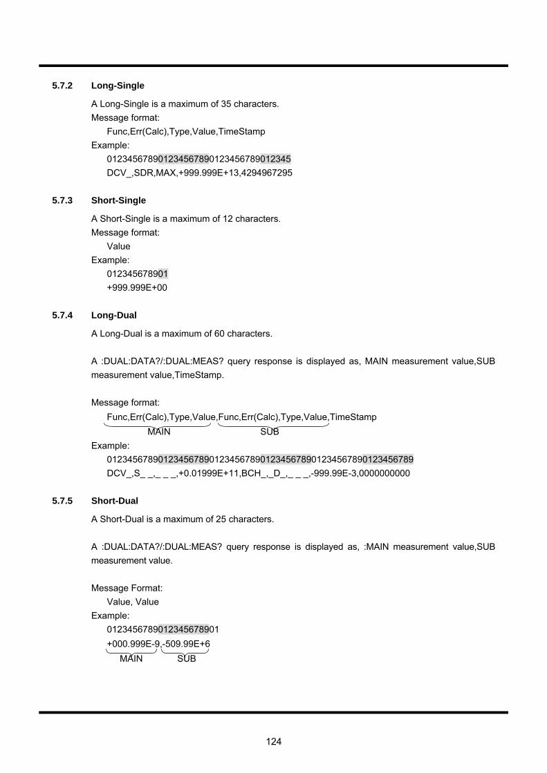
124
5.7.2 Long-Single
A Long-Single is a maximum of 35 characters. Message format:
Func,Err(Calc),Type,Value,TimeStamp Example:
012345678901234567890123456789012345 DCV_,SDR,MAX,+999.999E+13,4294967295
5.7.3 Short-Single
A Short-Single is a maximum of 12 characters. Message format:
Value Example:
012345678901 +999.999E+00
5.7.4 Long-Dual
A Long-Dual is a maximum of 60 characters. A :DUAL:DATA?/:DUAL:MEAS? query response is displayed as, MAIN measurement value,SUB measurement value,TimeStamp. Message format:
Func,Err(Calc),Type,Value,Func,Err(Calc),Type,Value,TimeStamp MAIN SUB Example:
012345678901234567890123456789012345678901234567890123456789 DCV_,S_ _,_ _ _,+0.01999E+11,BCH_,_D_,_ _ _,-999.99E-3,0000000000
5.7.5 Short-Dual
A Short-Dual is a maximum of 25 characters.
A :DUAL:DATA?/:DUAL:MEAS? query response is displayed as, :MAIN measurement value,SUB measurement value. Message Format:
Value, Value Example:
0123456789012345678901 +000.999E-9,-509.99E+6 MAIN SUB
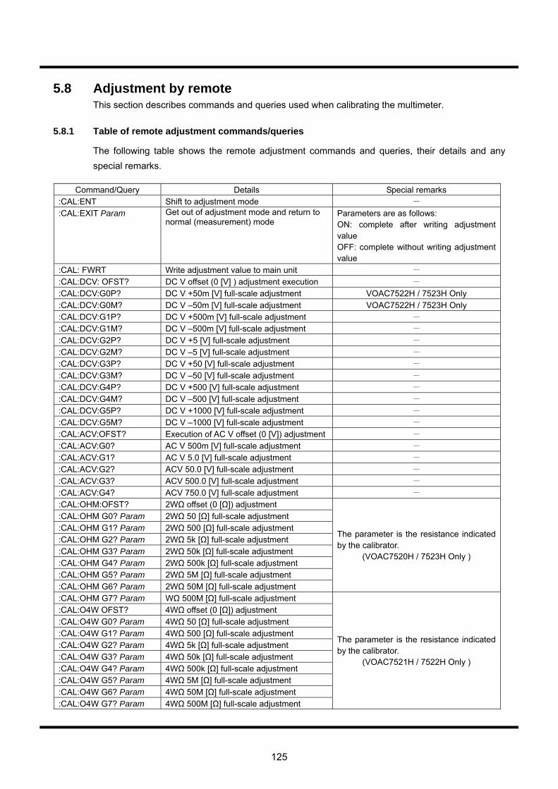
125
5.8 Adjustment by remote This section describes commands and queries used when calibrating the multimeter.
5.8.1 Table of remote adjustment commands/queries
The following table shows the remote adjustment commands and queries, their details and any special remarks.
Command/Query Details Special remarks :CAL:ENT Shift to adjustment mode - :CAL:EXIT Param Get out of adjustment mode and return to
normal (measurement) mode Parameters are as follows: ON: complete after writing adjustment value OFF: complete without writing adjustment value
:CAL: FWRT Write adjustment value to main unit - :CAL:DCV: OFST? DC V offset (0 [V] ) adjustment execution - :CAL:DCV:G0P? DC V +50m [V] full-scale adjustment VOAC7522H / 7523H Only :CAL:DCV:G0M? DC V –50m [V] full-scale adjustment VOAC7522H / 7523H Only :CAL:DCV:G1P? DC V +500m [V] full-scale adjustment - :CAL:DCV:G1M? DC V –500m [V] full-scale adjustment - :CAL:DCV:G2P? DC V +5 [V] full-scale adjustment - :CAL:DCV:G2M? DC V –5 [V] full-scale adjustment - :CAL:DCV:G3P? DC V +50 [V] full-scale adjustment - :CAL:DCV:G3M? DC V –50 [V] full-scale adjustment - :CAL:DCV:G4P? DC V +500 [V] full-scale adjustment - :CAL:DCV:G4M? DC V –500 [V] full-scale adjustment - :CAL:DCV:G5P? DC V +1000 [V] full-scale adjustment - :CAL:DCV:G5M? DC V –1000 [V] full-scale adjustment - :CAL:ACV:OFST? Execution of AC V offset (0 [V]) adjustment - :CAL:ACV:G0? AC V 500m [V] full-scale adjustment - :CAL:ACV:G1? AC V 5.0 [V] full-scale adjustment - :CAL:ACV:G2? ACV 50.0 [V] full-scale adjustment - :CAL:ACV:G3? ACV 500.0 [V] full-scale adjustment - :CAL:ACV:G4? ACV 750.0 [V] full-scale adjustment - :CAL:OHM:OFST? 2WΩ offset (0 [Ω]) adjustment :CAL:OHM G0? Param 2WΩ 50 [Ω] full-scale adjustment :CAL:OHM G1? Param 2WΩ 500 [Ω] full-scale adjustment :CAL:OHM G2? Param 2WΩ 5k [Ω] full-scale adjustment :CAL:OHM G3? Param 2WΩ 50k [Ω] full-scale adjustment :CAL:OHM G4? Param 2WΩ 500k [Ω] full-scale adjustment :CAL:OHM G5? Param 2WΩ 5M [Ω] full-scale adjustment :CAL:OHM G6? Param 2WΩ 50M [Ω] full-scale adjustment
The parameter is the resistance indicated by the calibrator.
(VOAC7520H / 7523H Only )
:CAL:OHM G7? Param WΩ 500M [Ω] full-scale adjustment :CAL:O4W OFST? 4WΩ offset (0 [Ω]) adjustment :CAL:O4W G0? Param 4WΩ 50 [Ω] full-scale adjustment :CAL:O4W G1? Param 4WΩ 500 [Ω] full-scale adjustment :CAL:O4W G2? Param 4WΩ 5k [Ω] full-scale adjustment :CAL:O4W G3? Param 4WΩ 50k [Ω] full-scale adjustment :CAL:O4W G4? Param 4WΩ 500k [Ω] full-scale adjustment :CAL:O4W G5? Param 4WΩ 5M [Ω] full-scale adjustment :CAL:O4W G6? Param 4WΩ 50M [Ω] full-scale adjustment :CAL:O4W G7? Param 4WΩ 500M [Ω] full-scale adjustment
The parameter is the resistance indicated by the calibrator.
(VOAC7521H / 7522H Only )
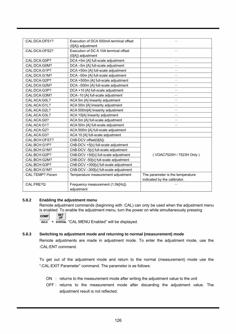
126
:CAL:DCA:OFS1? Execution of DCA 500mA terminal offset
(0[A]) adjustment -
:CAL:DCA:OFS2? Execution of DC A 10A terminal offset (0[A]) adjustment
-
:CAL:DCA:G0P? DCA +5m [A] full-scale adjustment - :CAL:DCA:G0M? DCA –5m [A] full-scale adjustment - :CAL:DCA:G1P? DCA +50m [A] full-scale adjustment - :CAL:DCA:G1M? DCA –50m [A] full-scale adjustment - :CAL:DCA:G2P? DCA +500m [A] full-scale adjustment - :CAL:DCA:G2M? DCA –500m [A] full-scale adjustment - :CAL:DCA:G3P? DCA +10 [A] full-scale adjustment - :CAL:DCA:G3M? DCA -10 [A] full-scale adjustment - :CAL:ACA:G0L? ACA 5m [A] linearity adjustment - :CAL:ACA:G1L? ACA 50m [A] linearity adjustment - :CAL:ACA:G2L? ACA 500m[A] linearity adjustment - :CAL:ACA:G3L? ACA 10[A] linearity adjustment - :CAL:ACA:G0? ACA 5m [A] full-scale adjustment - :CAL:ACA:G1? ACA 50m [A] full-scale adjustment - :CAL:ACA:G2? ACA 500m [A] full-scale adjustment :CAL:ACA:G3? ACA 10 [A] full-scale adjustment :CAL:BCH:OFST? ChB-DCV offset(0[A]) :CAL:BCH:G1P? ChB-DCV +5[v] full-scale adjustment :CAL:BCH:G1M? ChB-DCV -5[v] full-scale adjustment :CAL:BCH:G2P? ChB-DCV +50[v] full-scale adjustment :CAL:BCH:G2M? ChB-DCV -50[v] full-scale adjustment :CAL:BCH:G3P? ChB-DCV +300[v] full-scale adjustment :CAL:BCH:G1M? ChB-DCV –300[v] full-scale adjustment
( VOAC7520H / 7523H Only )
:CAL:TEMP? Param Temperature measurement adjustment The parameter is the temperature indicated by the calibrator.
:CAL:FRE?Q Frequency measurement (1.0k[Hz]) adjustment
-
5.8.2 Enabling the adjustment menu
Remote adjustment commands (beginning with :CAL) can only be used when the adjustment menu is enabled. To enable the adjustment menu, turn the power on while simultaneously pressing
+ . “CAL MENU Enabled” will be displayed.
5.8.3 Switching to adjustment mode and returning to normal (measurement) mode Remote adjustments are made in adjustment mode. To enter the adjustment mode, use the :CAL:ENT command. To get out of the adjustment mode and return to the normal (measurement) mode use the “:CAL:EXIT Parameter” command. The parameter is as follows:
ON : returns to the measurement mode after writing the adjustment value to the unit OFF : returns to the measurement mode after discarding the adjustment value. The
adjustment result is not reflected.
127
5.8.4 Writing the adjustment value Adjustments carried out in adjustment mode that are not written to the multimeter’s memory will not be enabled. Use the :CAL:FWRT command to write to memory. Writing to memory can also be completed by setting parameters with other commands when exiting the adjustment mode.
5.8.5 Adjustment menu The adjustment procedure for each item is as follows: 1. Connect the calibration signal to the output calibrator. The preparation for adjusting each item is the same as in manual calibration. See Section 5,
“Performance Inspections and Calibrations”, of the operation manual. 2. Send a query. To execute the adjustment, send a query corresponding to the item. Example: DC V, 50V range, full-scale calibration on minus side :CAL:DCV:G3M? 3. Receive the query response. All adjustment query responses are as follows: 0: adjustment succeeded (i.e., the adjustment result is within the specification) -1: adjustment failed (i.e., the adjustment result is outside the specification) Adjustment values for failed items will not be updated even if the value is written to the multimeter. In addition, the response to an adjustment query may take several dozen seconds. It is necessary to take measures, such as synchronous communication by SRQ, to ensure that a sufficient timeout is provided for external device timeouts.
5.8.6 Adjustment menu requiring parameters
Full-scale adjustment of resistance measurements (2-terminal and 4-terminal) and temperature measurement adjustments require the calibrator displayed values as parameters. Parameters should be entered in the <numeric program data> format. Example: 4 terminal, 500kΩ range full-scale calibration (i.e., calibrator output of 190.0016 k[Ω]) :CAL:O4M:G4? 190.002E3
128
6. SC-303A Compatible Mode When using remote control with the GP-IB unit, in addition to the standard multimeter command system, the command system used in previous models (SC-303A) may also be used. When using compatibility mode, functions that were not incorporated into previous models (dual function, scaling calculations, etc) cannot be used. Additionally, remote-control using the RD-232 and Ethernet interfaces will only use the standard command system.
6.1 Main multimeter configuration (manual) Manual configuration in the multimeter is required in order to specify whether to use the standard command system or the SC-303A compatible command system. Specification is made via the
“GPIB:OldComd,” which is accessed by pressing the and keys in the system menu.. Preset values for this, and its details are as in the following table:
Table 6. 1 GP-IB Old Command Settings Preset value Details
ON Operation using the SC-303A compatible command system.
OFF (factory default configuration)
Operation using the standard multimeter command system.
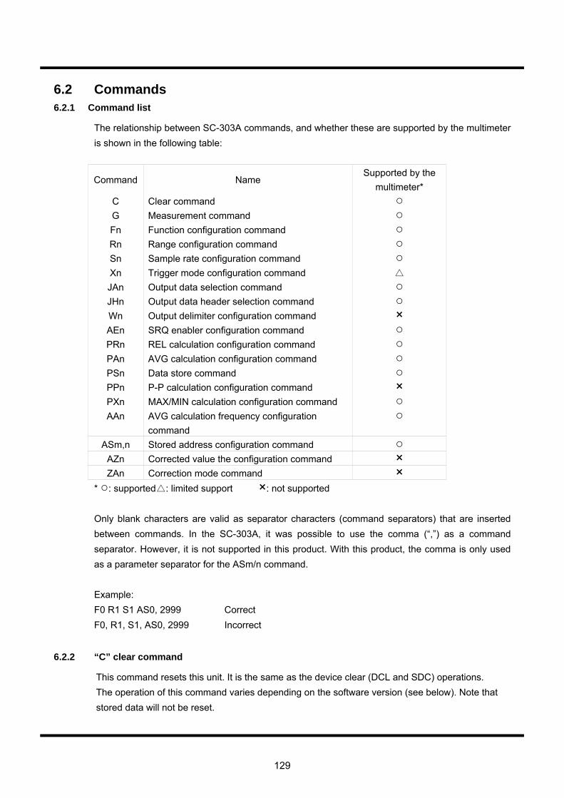
129
6.2 Commands 6.2.1 Command list
The relationship between SC-303A commands, and whether these are supported by the multimeter is shown in the following table:
Command Name Supported by the
multimeter* C Clear command G Measurement command Fn Function configuration command Rn Range configuration command Sn Sample rate configuration command Xn Trigger mode configuration command JAn Output data selection command JHn Output data header selection command Wn Output delimiter configuration command × AEn SRQ enabler configuration command PRn REL calculation configuration command PAn AVG calculation configuration command PSn Data store command PPn P-P calculation configuration command × PXn MAX/MIN calculation configuration command AAn AVG calculation frequency configuration
command
ASm,n Stored address configuration command AZn Corrected value the configuration command × ZAn Correction mode command ×
* : supported : limited support ×: not supported Only blank characters are valid as separator characters (command separators) that are inserted between commands. In the SC-303A, it was possible to use the comma (“,”) as a command separator. However, it is not supported in this product. With this product, the comma is only used as a parameter separator for the ASm/n command. Example: F0 R1 S1 AS0, 2999 Correct F0, R1, S1, AS0, 2999 Incorrect
6.2.2 “C” clear command
This command resets this unit. It is the same as the device clear (DCL and SDC) operations. The operation of this command varies depending on the software version (see below). Note that stored data will not be reset.
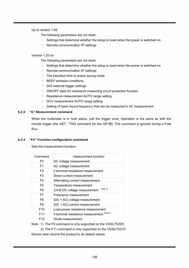
130
Up to version 1.09 The following parameters are not reset:
・ Settings that determine whether the setup is reset when the power is switched on ・ Remote communication I/F settings
Version 1.20 on The following parameters are not reset:
・ Settings that determine whether the setup is reset when the power is switched on ・ Remote communication I/F settings ・ The transition time to power saving mode ・ BEEP emission conditions ・ DIO external trigger settings ・ ON/OFF state for resistance measuring circuit protection function ・ Resistance measurement AUTO range setting ・ DCV measurement AUTO range setting ・ Setting of lower bound frequency that can be measured in AC measurement
6.2.3 “G” Measurement command
When the multimeter is in hold status, pull the trigger once. Operation is the same as with the remote trigger (the GET, *TRG command for the GP-IB). This command is ignored during a Free Run.
6.2.4 “Fn” Function configuration command
Sets the measurement function.
Command measurement function F0 DC voltage measurement F1 AC voltage measurement F2 2 terminal resistance measurement F3 Direct current measurement F4 Alternating current measurement F5 Temperature measurement F6 CH-B DC voltage measurement Note 1) F7 Frequency measurement F8 (DC + AC) voltage measurement F9 (DC + AC) current measurement
F10 Load power resistance measurement F11 4 terminal resistance measurement Note 2) F12 Diode measurement
Note 1) The F6 command is only supported on the VOAC7520H. 2) The F11 command is only supported on the VOAC7521H. Device clear returns the product to its default values.
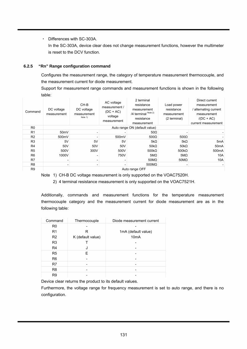
131
・ Differences with SC-303A. In the SC-303A, device clear does not change measurement functions, however the multimeter
is reset to the DCV function.
6.2.5 “Rn” Range configuration command
Configures the measurement range, the category of temperature measurement thermocouple, and the measurement current for diode measurement. Support for measurement range commands and measurement functions is shown in the following table:
Command DC voltage
measurement
CH-B DC voltage
measurement Note 1)
AC voltage measurement /
(DC + AC) voltage
measurement
2 terminal resistance
measurement /4 terminal Note 2)
resistance measurement
Load power resistance
measurement (2 terminal)
Direct current measurement
/ alternating current measurement
/(DC + AC) current measurement
R0 Auto range ON (default value) R1 50mV - - 50Ω - -R2 500mV - 500mV 500Ω 500Ω -R3 5V 5V 5V 5kΩ 5kΩ 5mAR4 50V 50V 50V 50kΩ 50kΩ 50mAR5 500V 300V 500V 500kΩ 500kΩ 500mAR6 1000V - 750V 5MΩ 5MΩ 10AR7 - - - 50MΩ 50MΩ 10AR8 - - - 500MΩ - -R9 Auto range OFF
Note 1) CH-B DC voltage measurement is only supported on the VOAC7520H. 2) 4 terminal resistance measurement is only supported on the VOAC7521H. Additionally, commands and measurement functions for the temperature measurement thermocouple category and the measurement current for diode measurement are as in the following table:
Command Thermocouple Diode measurement current R0 - - R1 R 1mA (default value) R2 K (default value) 10mA R3 T - R4 J - R5 E - R6 - - R7 - - R8 - - R9 - -
Device clear returns the product to its default values. Furthermore, the voltage range for frequency measurement is set to auto range, and there is no configuration.
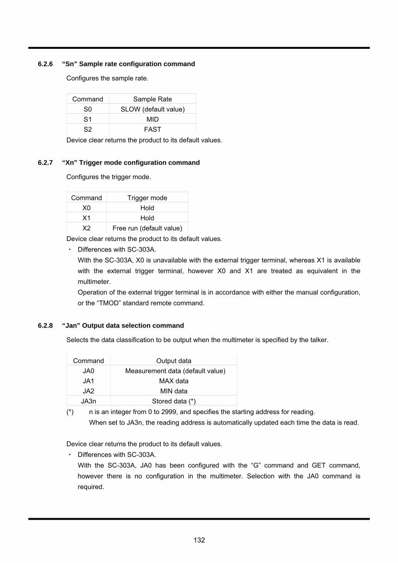
132
6.2.6 “Sn” Sample rate configuration command
Configures the sample rate.
Command Sample Rate S0 SLOW (default value) S1 MID S2 FAST
Device clear returns the product to its default values.
6.2.7 “Xn” Trigger mode configuration command
Configures the trigger mode.
Command Trigger mode X0 Hold X1 Hold X2 Free run (default value)
Device clear returns the product to its default values. ・ Differences with SC-303A. With the SC-303A, X0 is unavailable with the external trigger terminal, whereas X1 is available
with the external trigger terminal, however X0 and X1 are treated as equivalent in the multimeter.
Operation of the external trigger terminal is in accordance with either the manual configuration, or the “TMOD” standard remote command.
6.2.8 “Jan” Output data selection command
Selects the data classification to be output when the multimeter is specified by the talker.
Command Output data JA0 Measurement data (default value) JA1 MAX data JA2 MIN data
JA3n Stored data (*) (*) n is an integer from 0 to 2999, and specifies the starting address for reading.
When set to JA3n, the reading address is automatically updated each time the data is read. Device clear returns the product to its default values. ・ Differences with SC-303A. With the SC-303A, JA0 has been configured with the “G” command and GET command,
however there is no configuration in the multimeter. Selection with the JA0 command is required.
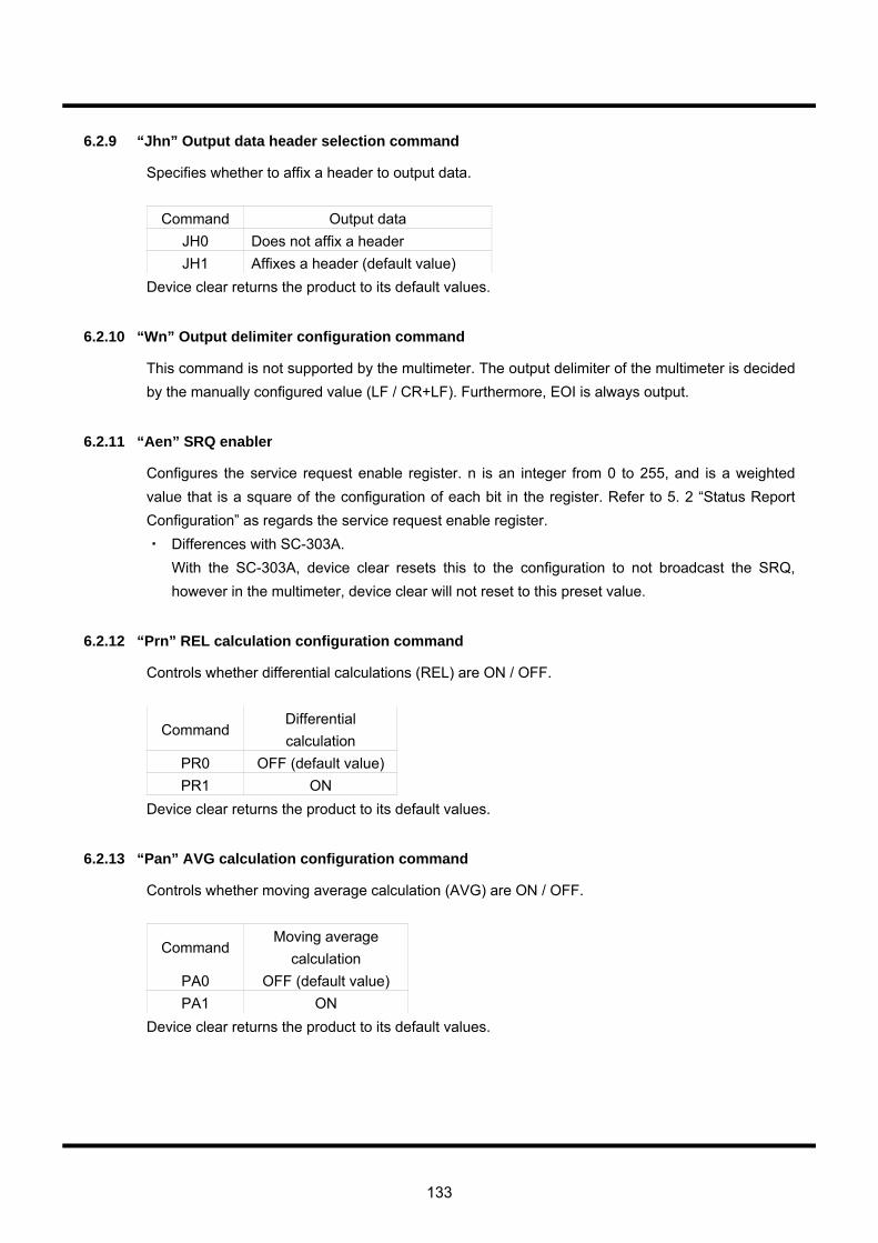
133
6.2.9 “Jhn” Output data header selection command
Specifies whether to affix a header to output data.
Command Output data JH0 Does not affix a header JH1 Affixes a header (default value)
Device clear returns the product to its default values.
6.2.10 “Wn” Output delimiter configuration command
This command is not supported by the multimeter. The output delimiter of the multimeter is decided by the manually configured value (LF / CR+LF). Furthermore, EOI is always output.
6.2.11 “Aen” SRQ enabler
Configures the service request enable register. n is an integer from 0 to 255, and is a weighted value that is a square of the configuration of each bit in the register. Refer to 5. 2 “Status Report Configuration” as regards the service request enable register. ・ Differences with SC-303A. With the SC-303A, device clear resets this to the configuration to not broadcast the SRQ,
however in the multimeter, device clear will not reset to this preset value.
6.2.12 “Prn” REL calculation configuration command
Controls whether differential calculations (REL) are ON / OFF.
Command Differential calculation
PR0 OFF (default value)PR1 ON
Device clear returns the product to its default values.
6.2.13 “Pan” AVG calculation configuration command
Controls whether moving average calculation (AVG) are ON / OFF.
Command Moving average
calculation PA0 OFF (default value) PA1 ON
Device clear returns the product to its default values.
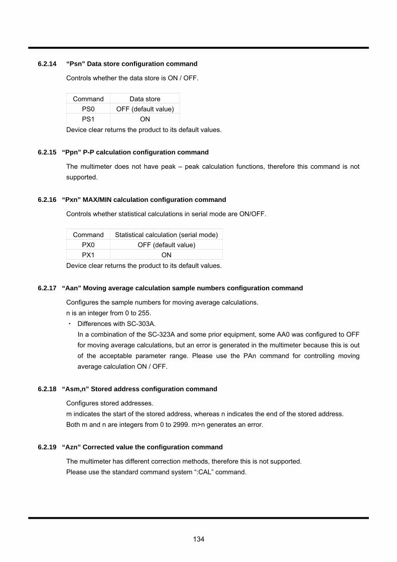
134
6.2.14 “Psn” Data store configuration command
Controls whether the data store is ON / OFF.
Command Data store PS0 OFF (default value) PS1 ON
Device clear returns the product to its default values.
6.2.15 “Ppn” P-P calculation configuration command
The multimeter does not have peak – peak calculation functions, therefore this command is not supported.
6.2.16 “Pxn” MAX/MIN calculation configuration command
Controls whether statistical calculations in serial mode are ON/OFF.
Command Statistical calculation (serial mode)PX0 OFF (default value) PX1 ON
Device clear returns the product to its default values.
6.2.17 “Aan” Moving average calculation sample numbers configuration command
Configures the sample numbers for moving average calculations. n is an integer from 0 to 255. ・ Differences with SC-303A. In a combination of the SC-323A and some prior equipment, some AA0 was configured to OFF
for moving average calculations, but an error is generated in the multimeter because this is out of the acceptable parameter range. Please use the PAn command for controlling moving average calculation ON / OFF.
6.2.18 “Asm,n” Stored address configuration command
Configures stored addresses. m indicates the start of the stored address, whereas n indicates the end of the stored address. Both m and n are integers from 0 to 2999. m>n generates an error.
6.2.19 “Azn” Corrected value the configuration command
The multimeter has different correction methods, therefore this is not supported. Please use the standard command system “:CAL” command.
135
6.2.20 “Zan” Correction mode command
The multimeter has different correction methods, therefore this is not supported. Please use the standard command system “:CAL” command.
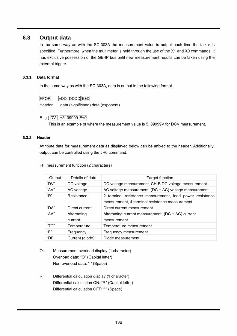
136
6.3 Output data In the same way as with the SC-303A the measurement value is output each time the talker is specified. Furthermore, when the multimeter is held through the use of the X1 and X0 commands, it has exclusive possession of the GB-IP bus until new measurement results can be taken using the external trigger.
6.3.1 Data format
In the same way as with the SC-303A, data is output in the following format. FFOR ±DD. DDDD E±D Header data (significand) data (exponent) E. g.) DV +5. 09999 E+0
This is an example of where the measurement value is 5. 09999V for DCV measurement.
6.3.2 Header
Attribute data for measurement data as displayed below can be affixed to the header. Additionally, output can be controlled using the JH0 command. FF: measurement function (2 characters)
Output Details of data Target function “DV” DC voltage DC voltage measurement, CH-B DC voltage measurement “AV” AC voltage AC voltage measurement, (DC + AC) voltage measurement “R” Resistance 2 terminal resistance measurement, load power resistance
measurement, 4 terminal resistance measurement “DA” Direct current Direct current measurement “AA” Alternating
current Alternating current measurement, (DC + AC) current measurement
“TC” Temperature Temperature measurement “F” Frequency Frequency measurement “DI” Current (diode) Diode measurement
O: Measurement overload display (1 character) Overload data: “O” (Capital letter) Non-overload data: “ ” (Space) R: Differential calculation display (1 character) Differential calculation ON: “R” (Capital letter) Differential calculation OFF: “ ” (Space)
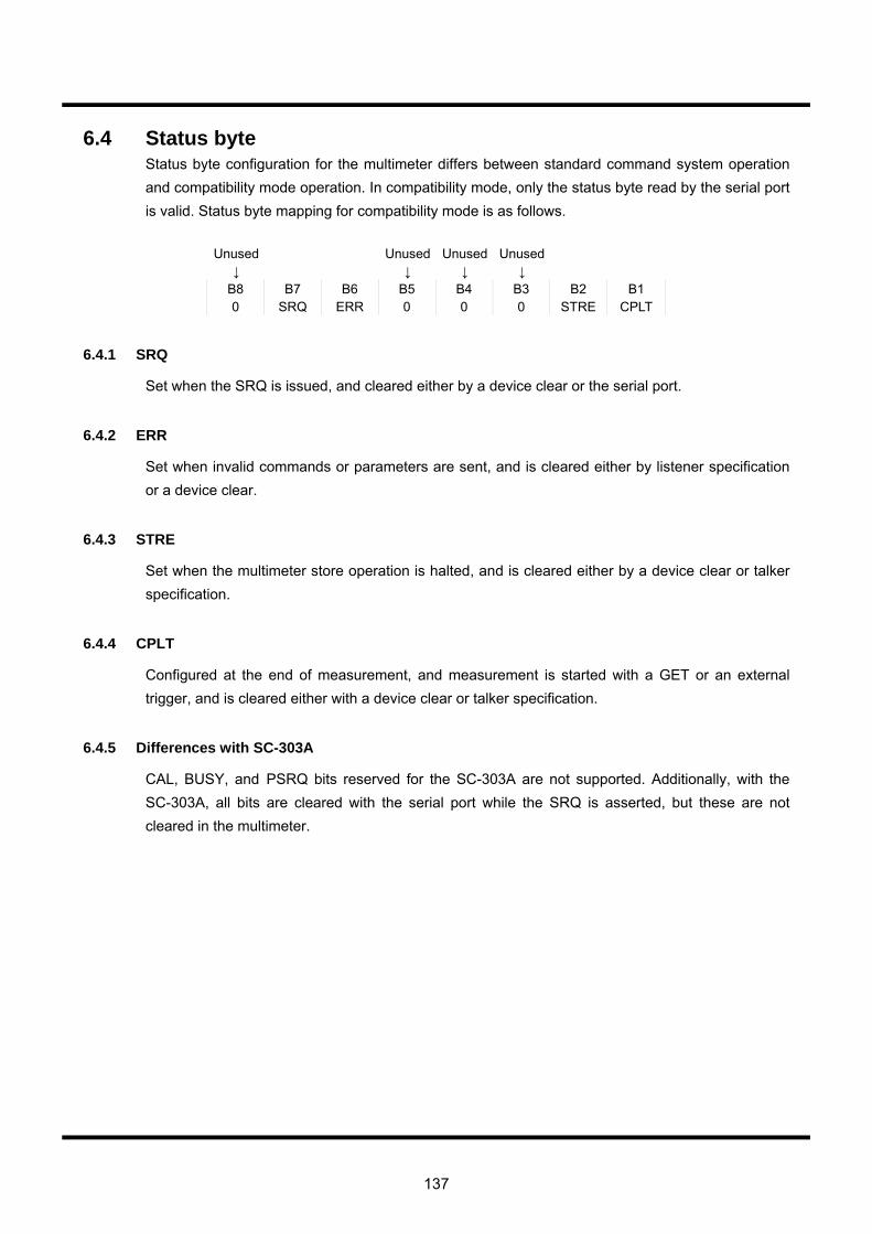
137
6.4 Status byte Status byte configuration for the multimeter differs between standard command system operation and compatibility mode operation. In compatibility mode, only the status byte read by the serial port is valid. Status byte mapping for compatibility mode is as follows.
Unused Unused Unused Unused ↓ ↓ ↓ ↓
B8 B7 B6 B5 B4 B3 B2 B1 0 SRQ ERR 0 0 0 STRE CPLT
6.4.1 SRQ
Set when the SRQ is issued, and cleared either by a device clear or the serial port.
6.4.2 ERR
Set when invalid commands or parameters are sent, and is cleared either by listener specification or a device clear.
6.4.3 STRE
Set when the multimeter store operation is halted, and is cleared either by a device clear or talker specification.
6.4.4 CPLT
Configured at the end of measurement, and measurement is started with a GET or an external trigger, and is cleared either with a device clear or talker specification.
6.4.5 Differences with SC-303A
CAL, BUSY, and PSRQ bits reserved for the SC-303A are not supported. Additionally, with the SC-303A, all bits are cleared with the serial port while the SRQ is asserted, but these are not cleared in the multimeter.
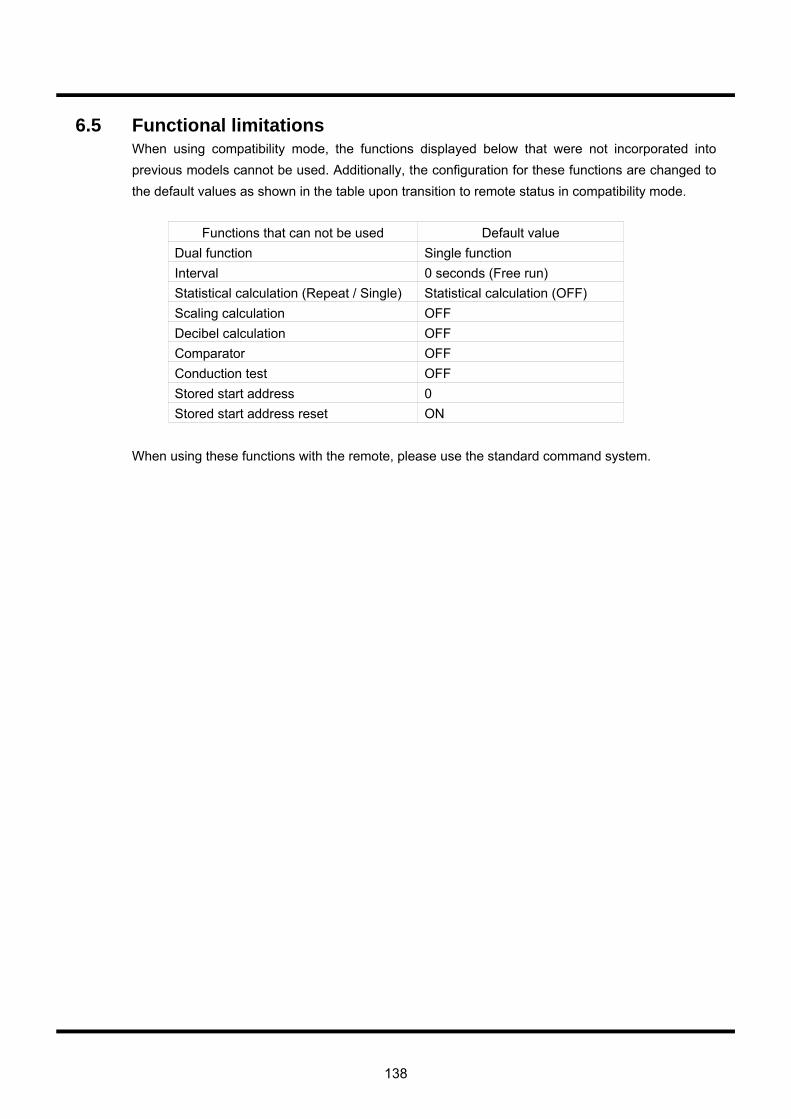
138
6.5 Functional limitations When using compatibility mode, the functions displayed below that were not incorporated into previous models cannot be used. Additionally, the configuration for these functions are changed to the default values as shown in the table upon transition to remote status in compatibility mode.
Functions that can not be used Default value Dual function Single function Interval 0 seconds (Free run) Statistical calculation (Repeat / Single) Statistical calculation (OFF) Scaling calculation OFF Decibel calculation OFF Comparator OFF Conduction test OFF Stored start address 0 Stored start address reset ON
When using these functions with the remote, please use the standard command system.

139
Memo

Address : 7-41 Kugayama 1-chome Suginami-ku, Tokyo, 168-8511 Japan Phone : +81 3 5370 5483 Facsimile : +81 3 5370 5230 Homepage : http://www.iti.iwatsu.co.jp


VOAC7520H/VOAC7521H/VOAC7522H/VOAC7523H