digital design: principles and practices chapter 8 sequential logic design practices
TRANSCRIPT
Digital Design:Principles and Practices
Chapter 8Sequential Logic Design Practices

8.4 Counters
3
Counter
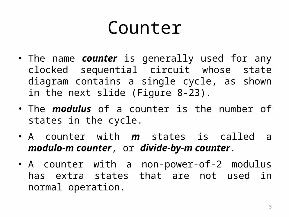
• The name counter is generally used for any clocked sequential circuit whose state diagram contains a single cycle, as shown in the next slide (Figure 8-23).
• The modulus of a counter is the number of states in the cycle.
• A counter with m states is called a modulo-m counter, or divide-by-m counter.
• A counter with a non-power-of-2 modulus has extra states that are not used in normal operation.

4
General Structure of a Counter State Diagram – A Single Cycle

8.4.1 Ripple Counters
6
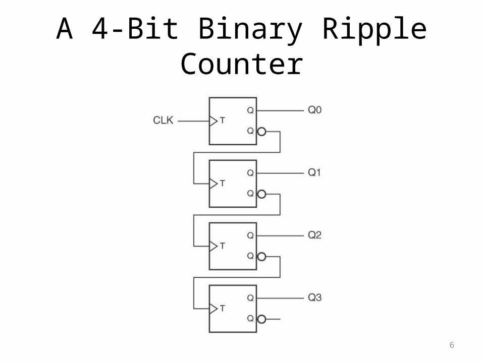
A 4-Bit Binary Ripple Counter
7
Ripple Counter• A T flip-flop changes state (toggles) on every rising edge of its clock
input.
• Thus, each bit of the counter toggles if and only if the immediately preceding bit changes from 1 to 0, it generates a carry to the next most significant bit.
• Although a ripple counter requires fewer components than any other type of binary counter, it does so at a price – it is slower than any other type of binary counter.
• In the worst case, when the most significant bit must change, the output is not valid until time n . tTQ after the rising edge of CLK, where tTQ is the propagation delay from input to output of a T flip-flop.

8
Synchronous Serial Counter
9
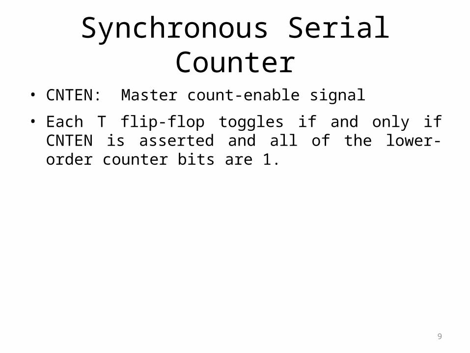
Synchronous Serial Counter
• CNTEN: Master count-enable signal
• Each T flip-flop toggles if and only if CNTEN is asserted and all of the lower-order counter bits are 1.
10
Synchronous Parallel Counter

11
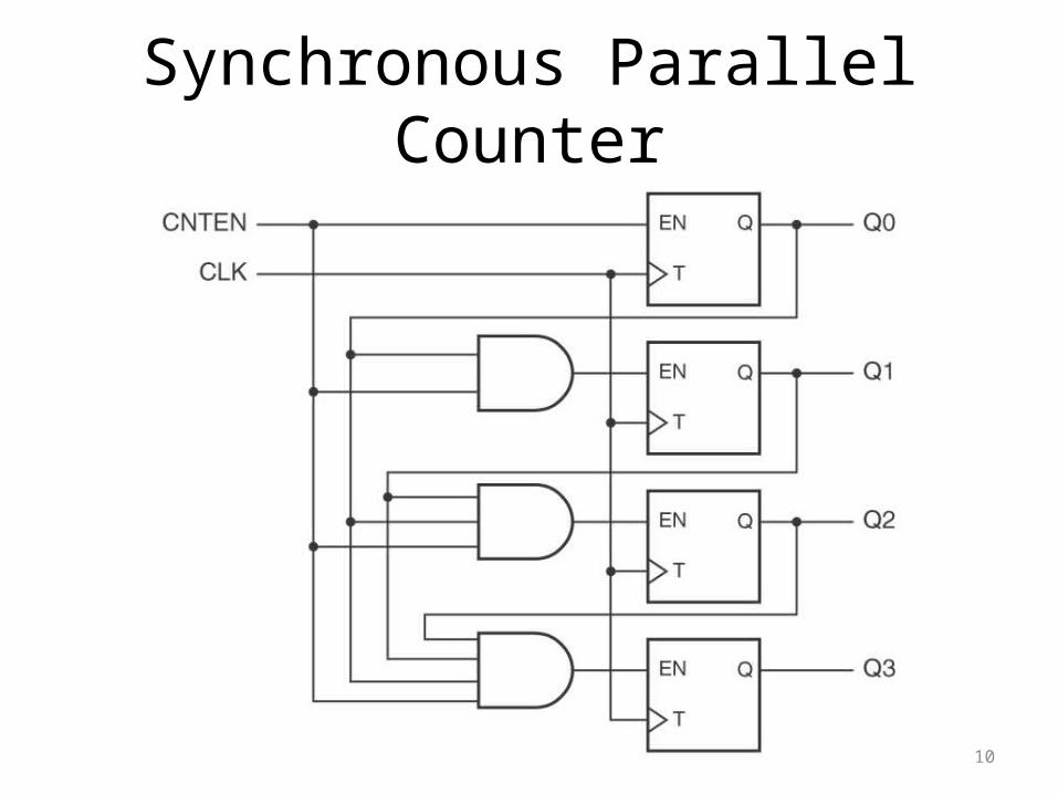
Synchronous Parallel Counter
• Synchronous parallel counter is the fastest binary counter structure.

2-Bit Asynchronous Counter
(LSB) (MSB)
Asynchronous Counters
• The clock input of an asynchronous counter is always connected only to the LSB flip-flop.
• Asynchronous counters are also known as ripple counters.

3-Bit Asynchronous Counter

Propagation Delay in 3-Bit Counter

4-Bit Asynchronous Counter

Asynchronous Decade Counter

Terms
• Recycle the transition of the counter from its final state
back to its original state.
• Modulus the number of states the maximum possible number of states
(maximum modulus) of a counter is 2n, where n is the number of flip-flops in the counter.
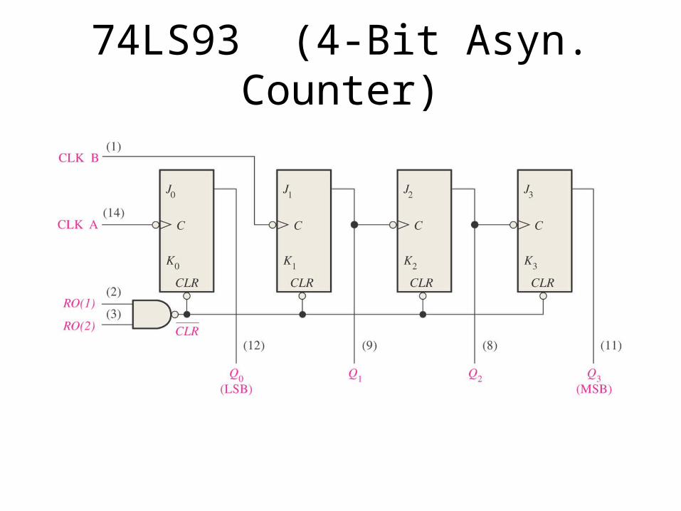
74LS93 (4-Bit Asyn. Counter)
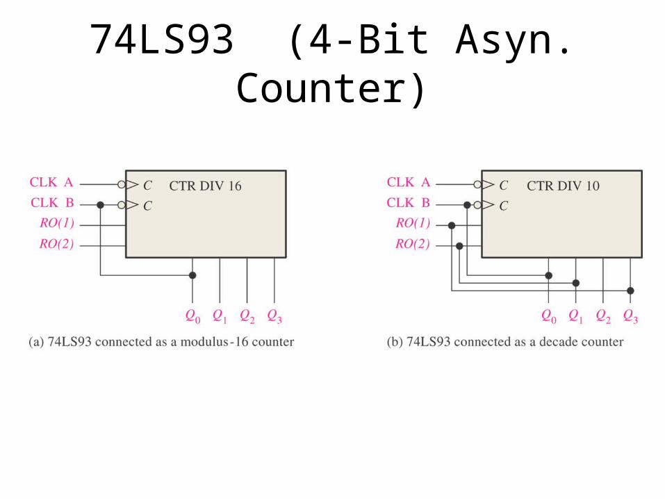
74LS93 (4-Bit Asyn. Counter)
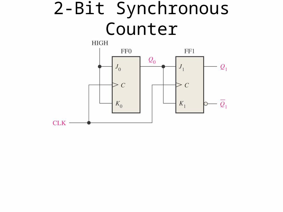
2-Bit Synchronous Counter

2-Bit Synchronous Counter

2-Bit Synchronous Counter

3-Bit Synchronous Counter

4-Bit Synchronous Counter

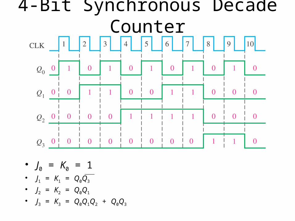
4-Bit Synchronous Decade Counter
• J0 = K0 = 1• J1 = K1 = Q0Q3
• J2 = K2 = Q0Q1
• J3 = K3 = Q0Q1Q2 + Q0Q3
4-Bit Synchronous Decade Counter
• J0 = K0 = 1• J1 = K1 = Q0Q3
• J2 = K2 = Q0Q1
• J3 = K3 = Q0Q1Q2 + Q0Q3

The Johnson Counter
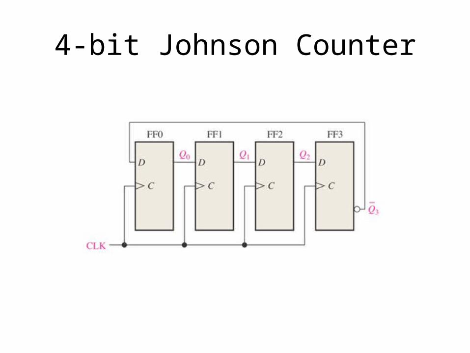
4-bit Johnson Counter

4-bit Johnson Counter

4-bit Johnson Counter
Clock Pulse Q0 Q1 Q2 Q3
0 0 0 0 0
1 1 0 0 0
2 1 1 0 0
3 1 1 1 0
4 1 1 1 1
5 0 1 1 1
6 0 0 1 1
7 0 0 0 1

5-bit Johnson Counter
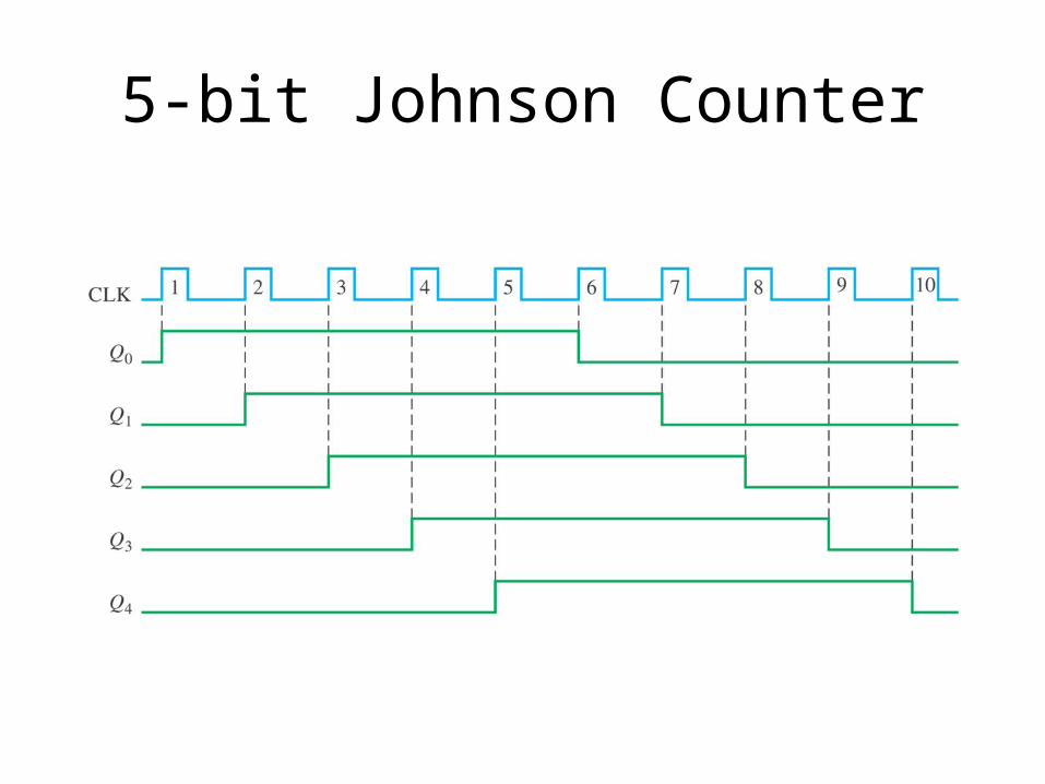
5-bit Johnson Counter
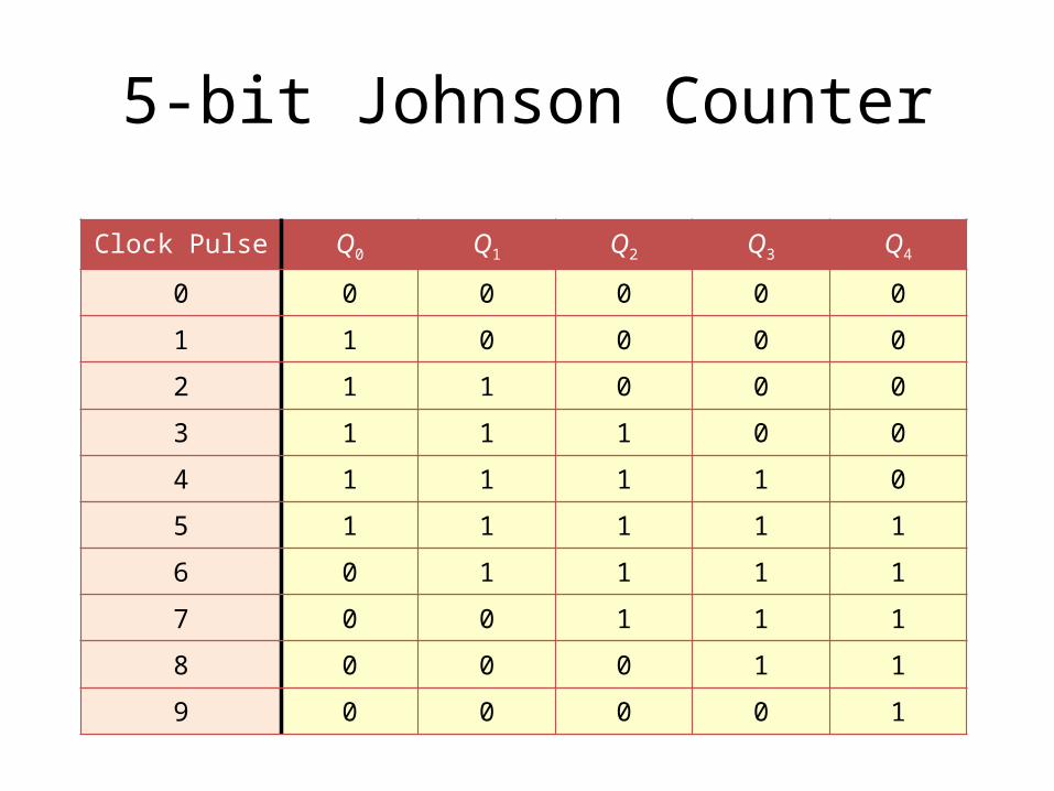
5-bit Johnson Counter
Clock Pulse Q0 Q1 Q2 Q3 Q4
0 0 0 0 0 0
1 1 0 0 0 0
2 1 1 0 0 0
3 1 1 1 0 0
4 1 1 1 1 0
5 1 1 1 1 1
6 0 1 1 1 1
7 0 0 1 1 1
8 0 0 0 1 1
9 0 0 0 0 1

The Johnson Counter
• In a Johnson counter, the complement of the output of the last flip-flop is connected back to the D input of the first flip-flop.
• A 4-bit Johnson counter has 8 states (or bit patterns).• A 5-bit Johnson counter has 10 states (or bit patterns).• In general, an n-bit Johnson counter will produce 2n states.

The Ring Counter

The Ring Counter

The Ring CounterClock Pulse Q0 Q1 Q2 Q3 Q4 Q5 Q6 Q7 Q8 Q9
0 1 0 0 0 0 0 0 0 0 01 0 1 0 0 0 0 0 0 0 02 0 0 1 0 0 0 0 0 0 03 0 0 0 1 0 0 0 0 0 04 0 0 0 0 1 0 0 0 0 05 0 0 0 0 0 1 0 0 0 06 0 0 0 0 0 0 1 0 0 07 0 0 0 0 0 0 0 1 0 08 0 0 0 0 0 0 0 0 1 09 0 0 0 0 0 0 0 0 0 1

8.5 Shift Registers

8.5.1 Shift-Register Structure
41
Shift Register
• A shift register is an n-bit register with a provision for shifting its stored data by one bit position at each tick of the clock.
• Shift Register Structures Serial-in, serial-out Serial-in, parallel-out Parallel-in, serial-out Parallel-in, parallel-out

42
Serial-In, Serial-Out Shift Register
43
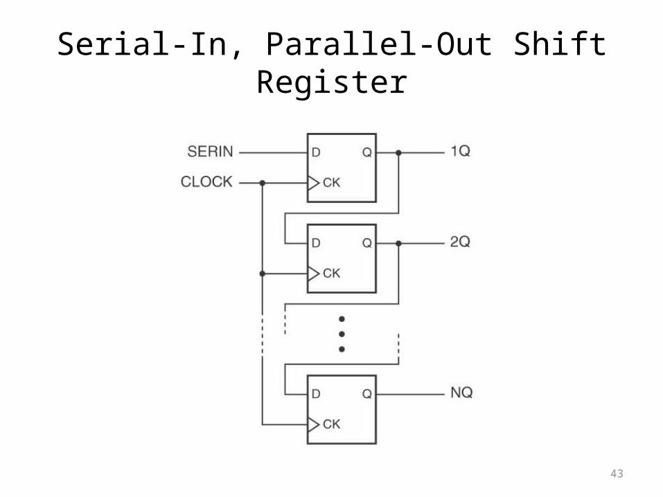
Serial-In, Parallel-Out Shift Register
44
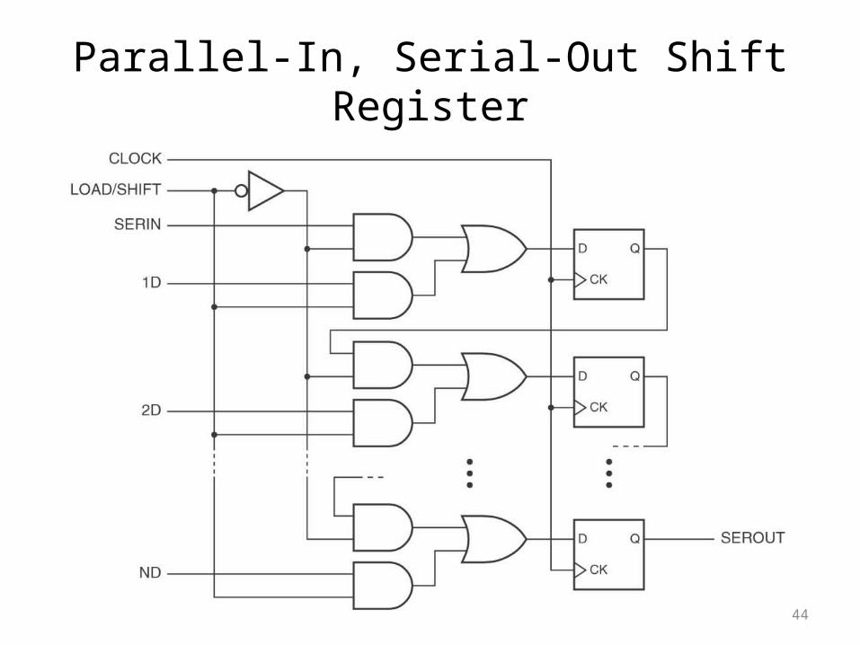
Parallel-In, Serial-Out Shift Register
45
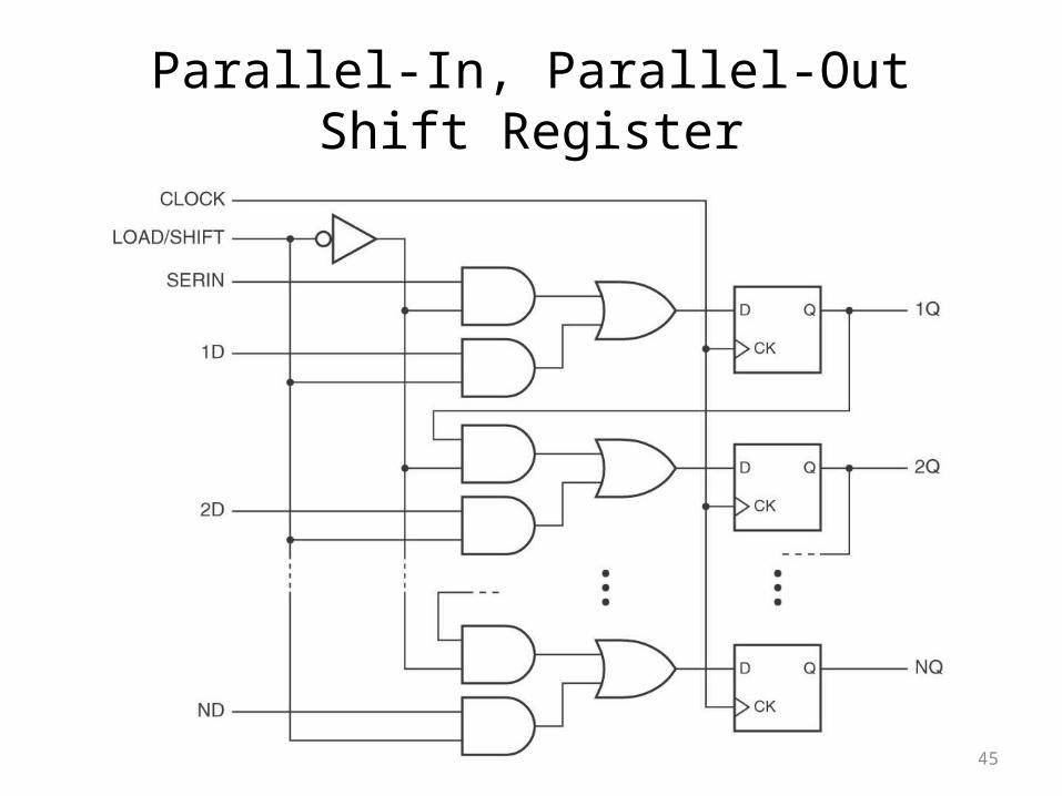
Parallel-In, Parallel-Out Shift Register

Basic Shift Register Functions
• Data Storage• Data Movement
Serial In / Serial Out Serial In / Parallel Out Parallel In / Serial Out Parallel In / Parallel Out Bi-directional
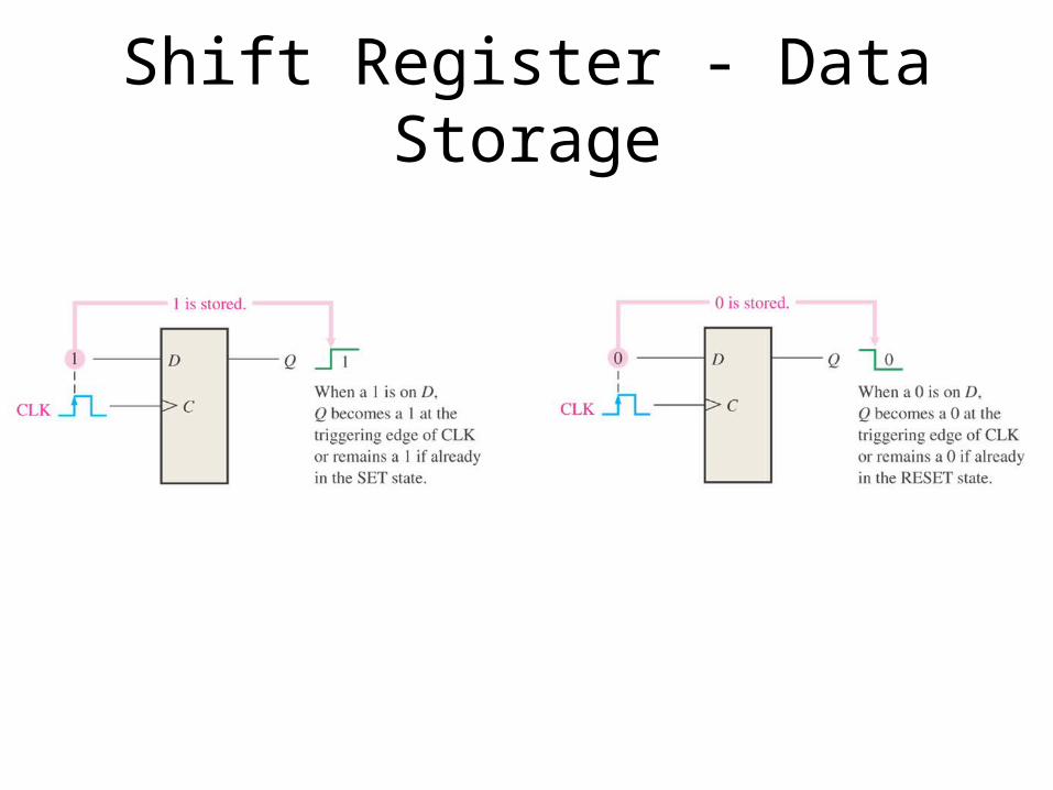
Shift Register - Data Storage
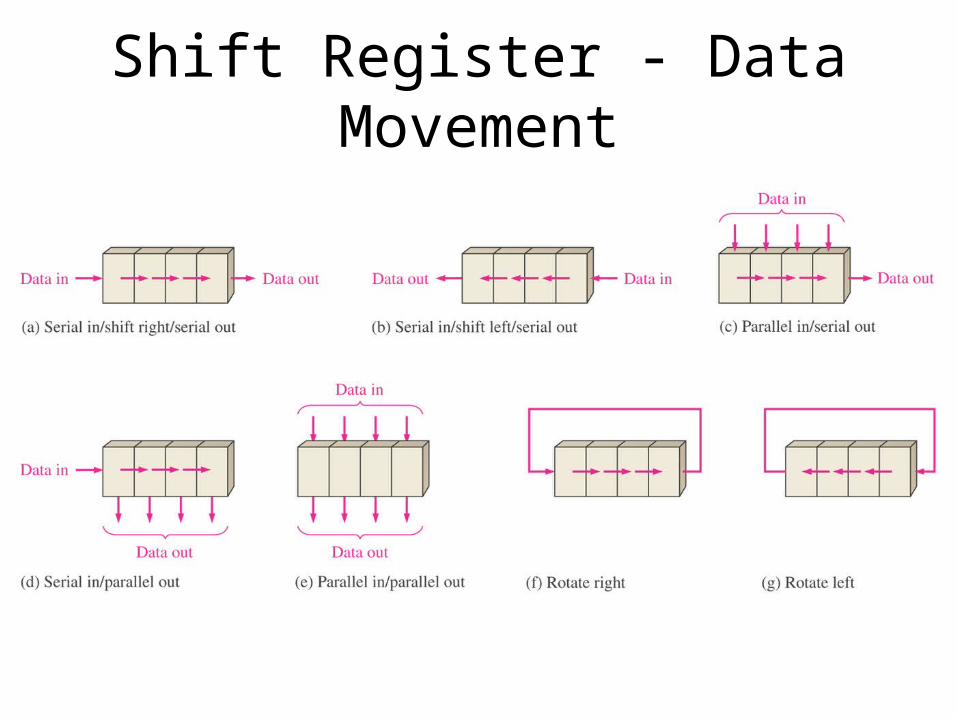
Shift Register - Data Movement

Serial In / Serial Out Shift Register
With four stages, this shift register can store up to four bits of data.

Figure 9–4 Four bits (1010) being entered serially into the register.

Figure 9–5 Four bits (1010) being serially shifted out of the register and replaced by all zeros.

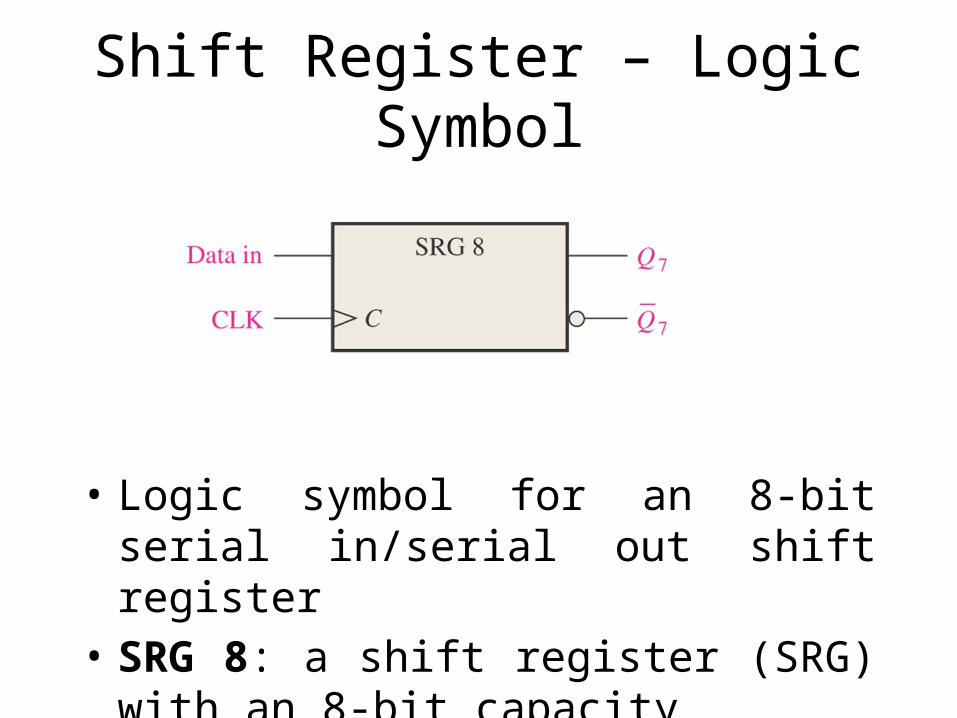
Shift Register – Logic Symbol
• Logic symbol for an 8-bit serial in/serial out shift register
• SRG 8: a shift register (SRG) with an 8-bit capacity

Serial In / Parallel Out Shift Register

Serial In / Parallel Out Shift Register
EXAMPLE 9-2Show the states of the 4-bit shift register (SRG 4) for the data input and clock waveform in Figure 9-9(a). The register initially contains all 1s.
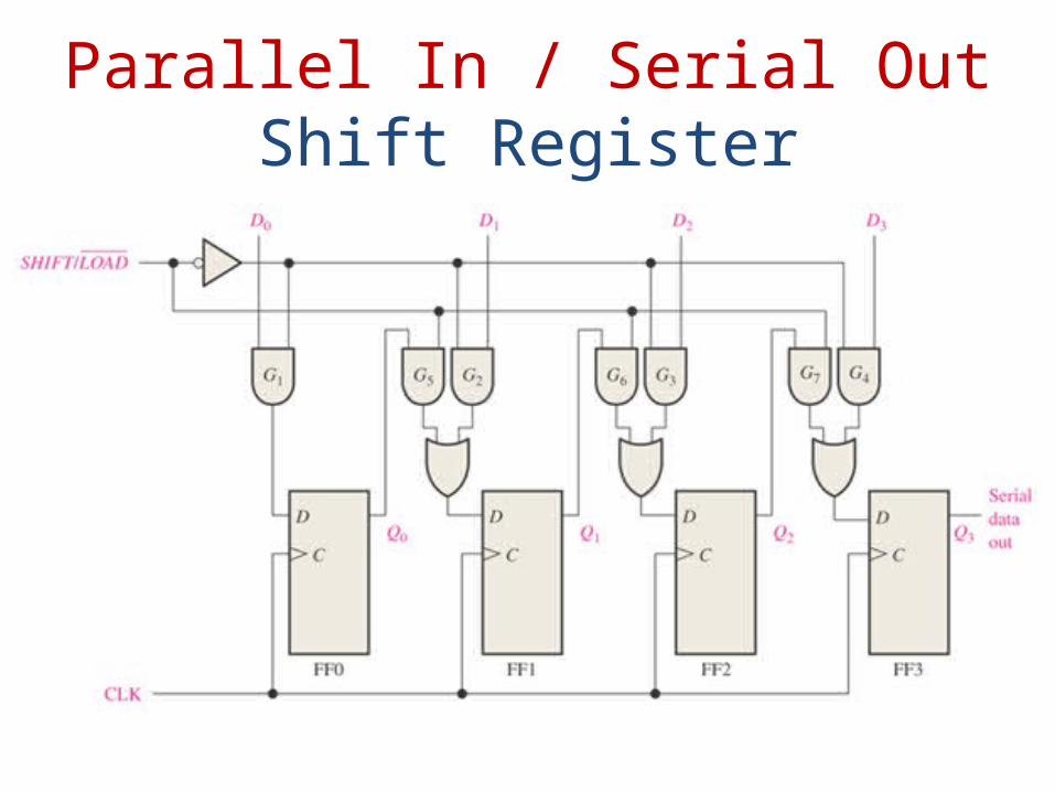
Parallel In / Serial Out Shift Register

Parallel In / Serial Out Shift Register
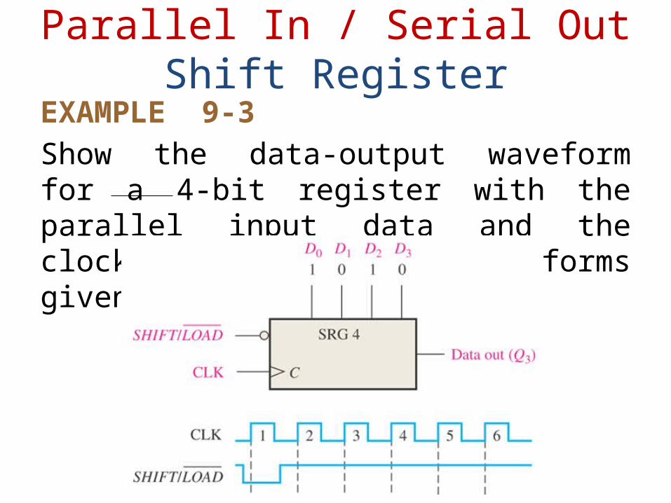
EXAMPLE 9-3Show the data-output waveform for a 4-bit register with the parallel input data and the clock and SHIFT/LOAD waveforms given in Figure 9-13(a).
Parallel In / Serial Out Shift Register

Parallel In / Parallel Out Shift Register
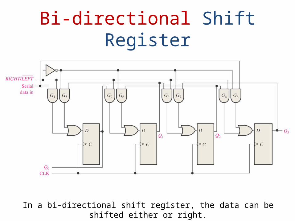
Bi-directional Shift Register
In a bi-directional shift register, the data can be shifted either or right.
8.8 Impediments to Synchronous Design

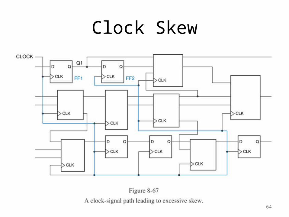
8.8.1 Clock Skew

63
Clock Skew• Synchronous systems using edge-triggered flip-flops work
properly only if all flip-flops see the triggering clock edge at the same time.
• The difference between arrival times of the clock at different devices is called clock skew.
64
Clock Skew

65
Clock Skew