digital cinema system specification v.1 · 9.4.3.3. show playback ... dci digital cinema system...
TRANSCRIPT
Digital Cinema Initiatives, LLC
ERRATUM # 9 (Chapter 9 Replacement)
to
Digital Cinema System Specification
Version 1.2 with Errata as of 30 August 2012 Incorporated
Approved 4 September 2014 Digital Cinema Initiatives, LLC, Member Representatives Committee
Copyright © 2005-‐2014 Digital Cinema Initiatives, LLC
CHAPTER 9 REPLACEMENT
DCI Digital Cinema System Specification v. 1.2 with Errata as of 30 August 2012 Incorporated
9. SECURITY 79 9.1. Introduction ................................................................................................................................................. 79 The following acronyms are introduced and used extensively in Section 9 80 9.2. Fundamental Security System Requirements ........................................................................................... 80 9.2.1. Content Protection and Piracy Prevention ............................................................................................... 80 9.2.2. Single Inventory and Interoperability ....................................................................................................... 80 9.2.3. Reliability ..................................................................................................................................................... 81 9.2.4. Support Forensics and Attack Detection ................................................................................................... 81 9.2.5. Resist Threats .............................................................................................................................................. 81 9.3. Security Architecture Overview ................................................................................................................. 81 9.3.1. Definitions .................................................................................................................................................... 81 9.3.2. Security Management Approach to Security ............................................................................................ 82 9.3.3. Security Messaging and Security Entities ................................................................................................. 83
9.3.3.1. Security Messages ............................................................................................................................. 83 Figure 14: Digital Cinema Security Message Flow 84
9.3.3.2. Security Entities ................................................................................................................................ 84 9.4. Theater Systems Security ........................................................................................................................... 85 9.4.1. Theater System Security Architecture ...................................................................................................... 85
9.4.1.1. Architecture Description and Comments ....................................................................................... 86 Figure 15: Digital Cinema Auditorium Security Implementations 89 9.4.2. Theater System Security Devices ............................................................................................................... 90
9.4.2.1. Equipment Suite ............................................................................................................................... 90 9.4.2.2. The Secure Processing Block (SPB) ................................................................................................ 90 9.4.2.3. Media Blocks (MBs) ......................................................................................................................... 91 9.4.2.4. Security Manager (SM) .................................................................................................................... 91 9.4.2.5. Screen Management System (SMS) ................................................................................................ 92 9.4.2.6. Projection Systems............................................................................................................................ 93
9.4.3. Theater Security Operations ...................................................................................................................... 93 9.4.3.1. Transport Layer Security (TLS) Establishment and Secure Processing Block (SPB)
Authentication .................................................................................................................................. 94 Figure 16: System Start-Up Overview 95
9.4.3.2. Pre-show Preparations ..................................................................................................................... 95 Figure 17: Pre-Show Overview 96
9.4.3.3. Show Playback .................................................................................................................................. 97 Figure 18: Show Playback Overview 98
9.4.3.4. Post Playback .................................................................................................................................... 98 Figure 19: Post Playback Overview 99
9.4.3.5. Functions of the Security Manager (SM) ....................................................................................... 99 9.4.3.6. Functional Requirements for Secure Processing Block Systems ................................................ 102
9.4.3.6.1. Normative Requirements: Projector Secure Processing Block .............................................. 103 9.4.3.6.2. Normative Requirements: Link Decryptor Block (LDB) ...................................................... 104 9.4.3.6.2.1. Normative Requirements for LD/LE SPB Devices ................................................................ 105 9.4.3.6.3. Normative Requirements: Image Media Block (IMB) .......................................................... 105 9.4.3.6.4. Normative Requirements: Outboard Media Block (OMB) .................................................... 106 9.4.3.6.5. Projector Authentication ........................................................................................................ 107 9.4.3.6.6. Permanently Married Implementations .................................................................................. 107
9.4.3.7. Theater System Clocks and Trustable Date-Time ....................................................................... 108 9.4.4. Link Encryption ........................................................................................................................................ 109
9.4.4.1. Special Auditorium Situations ....................................................................................................... 110 9.4.5. Intra-Theater Communications ............................................................................................................... 110
9.4.5.1. Transport Layer Security Sessions, End Points and Intra-Theater Messaging ........................ 111 9.4.5.2. Intra-Theater Message Definitions ............................................................................................... 111
9.4.5.2.1. Intra-theater Message Hierarchy ............................................................................................ 111

CHAPTER 9 REPLACEMENT
DCI Digital Cinema System Specification v. 1.2 with Errata as of 30 August 2012 Incorporated
9.4.5.2.2. Terms and Abbreviations ....................................................................................................... 111 9.4.5.2.3. General RRP Requirements ................................................................................................... 112 9.4.5.2.4. Request-Response Pairs (RRP) .............................................................................................. 112
9.4.5.3. Intra-Theater Message Details ...................................................................................................... 113 9.4.5.3.1. Screen Management System to Security Manager Messages ................................................ 113 9.4.5.3.2. Image Media Block Security Messaging ............................................................................... 113
9.4.6. Forensics ..................................................................................................................................................... 115 9.4.6.1. Forensic Marking ........................................................................................................................... 115
9.4.6.1.1. General Requirements ............................................................................................................ 116 9.4.6.1.2. Image/Picture Survivability Requirements ............................................................................ 118 9.4.6.1.3. Audio Survivability Requirements ......................................................................................... 118
9.4.6.2. Forensic Marking Operations ....................................................................................................... 119 9.4.6.3. Logging Subsystem ......................................................................................................................... 120
9.4.6.3.1. Logging Requirements ........................................................................................................... 121 9.4.6.3.2. Log Record and Report Format ............................................................................................. 122 9.4.6.3.3. Log Signatures and Integrity Controls ................................................................................... 122 9.4.6.3.4. Security of Log Record Sequencing ...................................................................................... 122 9.4.6.3.5. Log Upload Protocol over Theater Networks ........................................................................ 122 9.4.6.3.6. Log Filtering .......................................................................................................................... 123 9.4.6.3.7. Security Log Reports ............................................................................................................. 123 9.4.6.3.8. Log Record Information ........................................................................................................ 123 9.4.6.3.9. FIPS 140-2 Audit Mechanism Requirements ........................................................................ 125 9.4.6.3.10. Logging Failures .................................................................................................................... 125
9.5. Implementation Requirements ................................................................................................................. 126 9.5.1. Digital Certificates ..................................................................................................................................... 126
9.5.1.1. Single Certificate Implementations ............................................................................................... 126 9.5.1.2. Dual Certificate Implementations ................................................................................................. 127
9.5.2. Robustness and Physical Implementations ............................................................................................. 127 9.5.2.5. FIPS 140-2 Requirements for Type 1 Secure Processing Blocks ................................................ 130 9.5.2.6. Critical Security Parameters and D-Cinema Security Parameters ............................................ 133 9.5.2.7. SPB Firmware Modifications ........................................................................................................ 133
9.5.3. Screen Management System (SMS) ......................................................................................................... 134 9.5.4. Subtitle Processing .................................................................................................................................... 134 9.5.5. Compliance Testing ................................................................................................................................... 134 9.5.6. Communications Robustness .................................................................................................................... 135 9.6. Security Features and Trust Management .............................................................................................. 135 9.6.1. Digital Rights Management ...................................................................................................................... 135
9.6.1.1. Digital Rights Management: Screen Management System ......................................................... 136 9.6.1.2. Digital Rights Management: Security Manager (SM) ................................................................. 137 9.6.1.3. Digital Rights Management: Security Entity (SE) Equipment ................................................... 137 9.6.2. “Trust” and the Trusted Device List (TDL) ................................................................................. 138 9.6.2.1. Trust Domains ................................................................................................................................ 138 9.6.2.2. Authenticating Secure Processing Blocks & Linking Trust Through Certificates ................... 139 9.6.2.3. Identity vs. “Trust” ........................................................................................................................ 139 9.6.2.4. Revocation and Renewal of Trust ................................................................................................. 140
9.7. Essence Encryption and Cryptography ................................................................................................... 140 9.7.1. Content Transport ..................................................................................................................................... 140 9.7.2. Image and Sound Encryption ................................................................................................................... 140 9.7.3. Subtitle Encryption ................................................................................................................................... 141 9.7.4. Protection of Content Keys ....................................................................................................................... 141 9.7.5. Integrity Check Codes............................................................................................................................... 141 9.7.6. Key Generation and Derivation ............................................................................................................... 141 9.7.7. Numbers of Keys ....................................................................................................................................... 142 9.8. Digital Certificate, Extra-Theater Messages (ETM), and Key Delivery Messages (KDM)
Requirements ............................................................................................................................................. 142

CHAPTER 9 REPLACEMENT
DCI Digital Cinema System Specification v. 1.2 with Errata as of 30 August 2012 Incorporated CHAPTER 9 REPLACEMENT Page | 79
9. SECURITY
9.1. Introduction This section defines the requirements for Digital Cinema security. Though security is an end-to-end process, these specifications are focused on the exhibition environment. The high level business requirements for security are:
• Enable the decryption and playback of feature films, based upon business rules agreed upon by Exhibition and Distribution.
• Provide persistent security protection against unauthorized access, copying, editing, or playback of feature films.
• Provide records of security-related events. The high level technical requirements for security are:
• Meet the above business requirements. • Define an open security architecture. • Provide a minimum set of standards around which the exhibition security infrastructure can be
implemented by multiple equipment suppliers. Security is provided primarily through the application of encryption technology and the management of content key access. When content is transported and received in an encrypted fashion, it is necessary to establish standardized methods of delivering and utilizing decryption keys to unlock the content. This is known as key management. Associated with key exchange is DRM (Digital Rights Management), which establishes the rules for using content. The management of DRM is known as security management. DRM requirements include logging of content access and other security event information.
In the security architecture defined herein, security management functions are entrusted to a Security Manager (SM), a logically separable and functionally unique component of the architecture. The security system is referred to as the infrastructure that provides security features, and the Security Manager is at the heart of this infrastructure. The security system architecture is defined to provide open and standardized security operation and enable interoperability between an exhibition SM and the rest of the exhibition security infrastructure.
This specification originally required that a single SM be assigned to an auditorium projection booth. The requirement for a single SM is eliminated. Multiple SM’s per auditorium (each contained within a Media Block as further specified herein) is permitted by this specification, which enables Multiple Media Block (MMB) auditorium equipment configurations.
Section 9 SECURITY is organized as follows:
• Fundamental Security Requirements (Section 9.2)– System-level goals, which security implementations are required to meet.
• Security Architecture Overview (Section 9.3)– Definitions and description of the basic security architecture, security messaging, and role of the Security Manager.
CHAPTER 9 REPLACEMENT
DCI Digital Cinema System Specification v. 1.2 with Errata as of 30 August 2012 Incorporated CHAPTER 9 REPLACEMENT Page | 80
• Theater Systems Security (Section 9.4)– Security and equipment functions, behavior requirements and security operations at exhibition.
• Implementation Requirements (Section 9.5)– Requirements for equipment implementation, physical and logical robustness and certification.
• Security Features and Trust Management (Section 9.6) – The requirements and implementation of security policy and trust infrastructures.
• Essence Encryption and Cryptography (Section 9.7)– Cryptographic requirements for essence encryption and related cryptography.
• Digital Certificates, Extra-Theater Message and Key Delivery Message Requirements (Section 9.8.) – Detailed requirements for Digital Certificates, Extra-Theater Message and Key Delivery Message.
The following acronyms are introduced and used extensively in Section 9 SM Security Manager KDM Key Delivery Message ETM Extra-Theater Message ITM Intra-Theater Message TDL Trusted Device List FM Forensic Marking (Marker) SE Security Entity SPB Secure Processing Block RRP Request-Response Pairs
9.2. Fundamental Security System Requirements This section describes the goals for the security system. Cryptographic security requires communications connectivity between Distribution and Exhibition, above what is required for 35mm film. However, at no time do security requirements mandate continuous on-line connectivity to an exhibition facility.
Note: Due to the dynamic nature of security technology, DCI reserves the right, at some future time, to update requirements and may require changes to Digital Cinema systems as situations warrant.
9.2.1. Content Protection and Piracy Prevention The security system shall provide a means for the securing of content against unauthorized access, copying, editing, and playback. Protection shall be standardized primarily through the application of encryption technology, management of content key access and robust logging.
9.2.2. Single Inventory and Interoperability The security system shall support a single inventory Digital Cinema Package (DCP) delivered to every compliant theater installation. The security system architecture shall support file interoperability for both the Digital Cinema Package (DCP) and the Key Delivery Message (KDM). The security system architecture shall require system interoperability between Security Manager (SM) and Screen Management System (SMS).

CHAPTER 9 REPLACEMENT
DCI Digital Cinema System Specification v. 1.2 with Errata as of 30 August 2012 Incorporated CHAPTER 9 REPLACEMENT Page | 81
9.2.3. Reliability The security system shall recognize that “the show must go on” except in extreme circumstances. The model shall support intelligent means to locate failures expeditiously, and support field replaceable security devices.
9.2.4. Support Forensics and Attack Detection • The security system shall produce records of the access to secured content at authorized
facilities. • The security system shall support techniques to expose security attacks in process prior to an
actual loss. • The security system shall support techniques (e.g., Forensic Marking) to implant evidence of
origin of the content for use in tracing unauthorized copies of the content to the source. • The security system shall support the interface(s) and operation of anti-camcorder devices.
This may include, but is not limited to, the ability to log the results of an anti-camcorder (detection of a camcorder event) or a non-functional anti-camcorder-ing system.
9.2.5. Resist Threats The security system shall support prevention and detection of the following threats:
• Content theft (piracy) – as noted above • Unauthorized exhibition (e.g., at wrong facility) • Manipulation of content (e.g., editing) • Un-logged usage of content • Denial of Service
9.3. Security Architecture Overview This section describes the architectural elements and fundamental operation of the Digital Cinema security system.
9.3.1. Definitions • Content – The digital representation of a visual, audio or subtitled program. Content exists
in several forms (encrypted/plaintext, compressed/uncompressed, etc) at various stages of the process in the Digital Cinema system.
• Digital Cinema Package (DCP) – The standardized form of content intended for delivery to theatrical exhibition facilities. DCP content components are selectively encrypted by the Rights Owner.
• Equipment Suite – The set of one or more Secure Processing Blocks associated with one Security Manager that collectively support essence playback through a projector. For example, an IMB and a projector (with or without Link Encryption) comprise a suite. A stand-alone Outboard Media Block (“OMB”, see below) is not connected to a projector and is not part of an Equipment Suite.
• Extra-Theater Message (ETM) – One-way information packet that passes into or out of, the exhibition facility. The ETM is a generic message container.

CHAPTER 9 REPLACEMENT
DCI Digital Cinema System Specification v. 1.2 with Errata as of 30 August 2012 Incorporated CHAPTER 9 REPLACEMENT Page | 82
• Forensic Mark – The generic term used in this specification for any or all of the following: watermarking, fingerprinting, and/or forensic watermarking functions used at the time of playback.
• Intra-Theater Message (ITM) – The data packet that passes between Secure Processing Blocks assigned to a single Equipment Suite. ITM(s) operate on two-way channels.
• Key Delivery Message (KDM) – The Extra Theater Message (ETM) for delivering content keys and Trusted Device List (TDL) to exhibition locations.
• Log Data – The data produced and stored as a result of security system activity. • Media Block (MB) – A type of Secure Processing Block that contains a Security Manager and
performs media decryption. This specification defines the Image Media Block (IMB) and the Outboard Media Block (OMB).
• Multiple Media Block (MMB) – Refers to a projection booth configuration containing more than one Media Block.
• Rights Owner – The generic term used to describe the party having authority over content to negotiate terms of engagements (e.g., a studio or distributor).
• Screen Management System (SMS) – A (non-secure) Security Entity (SE) that directs security functions for a single auditorium on behalf of exhibition management.
• Secure Processing Block (SPB) – A Security Entity (SE) which provides a physical and logical protection perimeter around other SEs.
• Security Data – The keys and associated parameters required for access to content, and managed by Security Managers.
• Security Entity (SE) – A logical processing device which executes a distinct security process or function. SEs are not distinguished from other theater equipment by being physically secure, but by the specific security function that they perform (see Section 9.3.3 Security Messaging and Security Entities).
• Security Interface – A standardized point of interoperability for security messaging. • Security Management – The process of securely distributing, storing and utilizing Security
Data in order to access content. • Security Manager (SM) – A Security Entity (SE) that is entrusted to control Security Data
according to a defined policy. There shall be one SM within each MB. • Stakeholder – A party involved in a business agreement relating to distribution and
exhibition of specific Content. • Trusted Device List (TDL) – A list of specified security devices which are approved to
participate in playback of a particular composition at the exhibition facility.
9.3.2. Security Management Approach to Security The security architecture described herein distinguishes security management from content management. Once content is encrypted, it is “purpose neutral and safe” and can be allowed to take any path desired at any time to any destination. Thus, content management (physical distribution) can be implemented along lines that are oriented towards business needs, commercial cost effectiveness, and convenience. “Purpose neutral and safe” means once content is encrypted, its purpose has been neutralized (as to the content type, information contained, etc.) and it is safe (one does not care where it goes, how it gets there or who has access to it).

CHAPTER 9 REPLACEMENT
DCI Digital Cinema System Specification v. 1.2 with Errata as of 30 August 2012 Incorporated CHAPTER 9 REPLACEMENT Page | 83
Access to encrypted content is controlled by the security management function. That is, content access is enabled or denied through control of Security Data. This function is entrusted to a Security Manager (SM), a logically separable and functionally unique component of the architecture. At exhibition, the SM controls Security Data, and consequently, access to content.
At the theater, access to content is provided via one or more Media Blocks (MB), each containing an SM. For each playback, each SM will require, and be delivered, one or more unique keys to unlock encrypted content files. All distributors will share the SM(s).
Each key is delivered in a Key Delivery Message (KDM) with a specified play period. That is defined as the time window when the key is authorized to unlock the content. There is a start time/date and a stop time/date associated with each key. The authorized window for each key will be part of the normal engagement negotiation between Exhibition and Distribution.
9.3.3. Security Messaging and Security Entities The security system described herein implements a standardized open architecture in which equipment used at exhibition facilities can be sourced from multiple, competing suppliers. In order to achieve interoperable security operation, the security system design for Exhibition, specifies a standard message set for interoperable communications between standardized security devices.
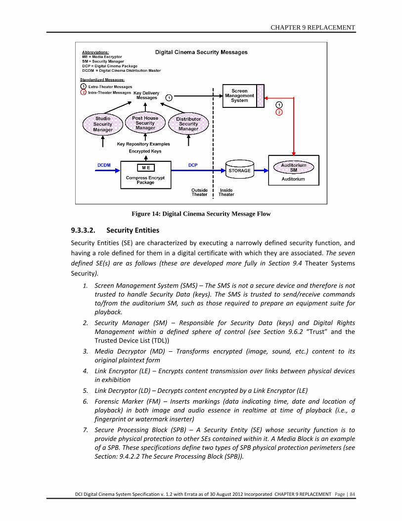
9.3.3.1. Security Messages There are two classes of messages in the architecture:
• Extra-theater Messages (ETM) – These are self-contained one-way messages that move Security Data and information outside or within the theater. These specifications have defined a fundamental message structure for a generic ETM, the requirements for which are normative and given in Section 9.8
• Intra-theater Message (ITM) – Messages that move security information within the auditorium over a real-time two-way channel. Requirements for the ITM infrastructure are given in Section 9.4.5 Intra-Theater Communications.
Figure 14: shows typical locations of SM functions6, ETM7 and ITM message interfaces. ETM message types are labeled with a black 1 and ITM messages with a red 2.
6 There may be various types of SM functions. These specifications are focused on the auditorium SM and its security management roles. SM functional and behavioral requirements are specified in Section 9.4.3 Theater Security Operations
7 The KDM is a type of ETM, and its creation location may vary. The KDM is normatively specified in Section 9.8
CHAPTER 9 REPLACEMENT
DCI Digital Cinema System Specification v. 1.2 with Errata as of 30 August 2012 Incorporated CHAPTER 9 REPLACEMENT Page | 84
Figure 14: Digital Cinema Security Message Flow
9.3.3.2. Security Entities Security Entities (SE) are characterized by executing a narrowly defined security function, and having a role defined for them in a digital certificate with which they are associated. The seven defined SE(s) are as follows (these are developed more fully in Section 9.4 Theater Systems Security).
1. Screen Management System (SMS) – The SMS is not a secure device and therefore is not trusted to handle Security Data (keys). The SMS is trusted to send/receive commands to/from the auditorium SM, such as those required to prepare an equipment suite for playback.
2. Security Manager (SM) – Responsible for Security Data (keys) and Digital Rights Management within a defined sphere of control (see Section 9.6.2 “Trust” and the Trusted Device List (TDL))
3. Media Decryptor (MD) – Transforms encrypted (image, sound, etc.) content to its original plaintext form
4. Link Encryptor (LE) – Encrypts content transmission over links between physical devices in exhibition
5. Link Decryptor (LD) – Decrypts content encrypted by a Link Encryptor (LE) 6. Forensic Marker (FM) – Inserts markings (data indicating time, date and location of
playback) in both image and audio essence in realtime at time of playback (i.e., a fingerprint or watermark inserter)
7. Secure Processing Block (SPB) – A Security Entity (SE) whose security function is to provide physical protection to other SEs contained within it. A Media Block is an example of a SPB. These specifications define two types of SPB physical protection perimeters (see Section: 9.4.2.2 The Secure Processing Block (SPB)).
CHAPTER 9 REPLACEMENT
DCI Digital Cinema System Specification v. 1.2 with Errata as of 30 August 2012 Incorporated CHAPTER 9 REPLACEMENT Page | 85
Security Entity Notes:
• The term Security Entity should not be confused with secure entity. The term secure entity is not normatively defined or used in these specifications, as the SPB function serves this purpose, and is normatively defined.
• The Link Encryptor and Link Decryptor Security Entities exist only when Link Encryption is used.
• The SMS is not a secure device, and is sometimes viewed as part of the media server, or as part of the TMS. These security specifications focus on the SMS as the auditorium controlling device, independently of its scope or totality of other functions it may provide (see Section: 9.4.2.5 Screen Management System (SMS)).
9.4. Theater Systems Security
9.4.1. Theater System Security Architecture The Theater System is comprised of those components, at an Exhibition location, that are required by the security system to support playback of a show. Once in possession of the complete DCP and its associated KDMs, the theater security system can independently enable playback of the composition.
Theater System Security requirements are:
1. Each auditorium shall have one or more Image Media Blocks (IMB), each associated with one projector. Each auditorium may have Outboard Media Block(s) (OMB) as further defined herein.
2. The IMB SM shall have knowledge of the projector it enables, by being able to authenticate that the projector has been certified to meet content protection requirements. Authentication shall be assured via a projector certificate, which shall be associated with the projector’s SPB type 2 (see Section 9.5.1 Digital Certificates and Section 9.5.2 Robustness and Physical Implementations).
3. The IMB shall include image, audio and subtitle decryption capability. An OMB shall decrypt only the content essence types designated by this specification (see Section 9.4.3.6.4 Normative Requirements: Outboard Media Block).
4. The IMB shall include image and audio Forensic Marking (FM) capability. The OMB may include FM for the content essence it decrypts, as defined by the requirements of the OMB normative requirements Section 9.4.3.6.4.
5. If Link Encryption (LE) exists, the Link Decryptor (LD) Block shall be authenticated to the IMB SM.
6. All Media Blocks and Link Decryptor Blocks shall be of the SPB type 1 (see Section 9.4.2.2. The Secure Processing Block (SPB)), and shall be field replaceable, but non-field serviceable. 8
7. Secure Processing Block (SPB) devices (and the SEs contained within them) shall have normative security and operational behavior requirements specified. Security Managers shall monitor the functioning of all SPB/SE devices and invoke controls to prevent use of improperly operating security equipment. To the extent possible, all security devices shall be
8 “Non-field serviceable” means not serviceable by other than the equipment vendor or his authorized and supervised service repair depot (see Section 9.5.2.3 Repair and Renewal)

CHAPTER 9 REPLACEMENT
DCI Digital Cinema System Specification v. 1.2 with Errata as of 30 August 2012 Incorporated CHAPTER 9 REPLACEMENT Page | 86
designed with self-test capability to announce and log failures and take themselves out of service.
Figure 15 presents the two fundamental auditorium security system architectures, with and without Link Encryption, and the security message types ETM and ITM. This diagram does not attempt to detail functions that are unrelated to security (e.g., decoding), but does anticipate such functions by noting where plain text content exists.
Though not shown in Figure 15: Digital Cinema Auditorium Security Implementations, but as indicated in the requirements above, every auditorium shall support image, audio, and subtitle decryption9, and image and audio Forensic Marking.
This specification also includes requirements for projection booth operation with equipment configurations beyond those shown in Figure 15 as follows:
• Special Auditorium Situations – An auditorium Equipment Suite may enable the use of more than one projection system associated with a single Image Media Block (IMB) in a given auditorium, multiple Link Encryption stages and/or an LD/LE SPB image processing device (see Section 9.4.4.1 "Special Auditorium Situations").
• Multiple Media Block (MMB) – Refers to the use of the IMB and one or more Outboard Media Blocks (OMB) to support playout. This enables flexibility to provide media processing beyond that specified for the IMB. Additionally, MMB provides requirements for multiple IMB operation to support multiple projectors (i.e., as alternative to the above Special Auditorium Situation).
The Special Auditorium Situation expands the utility of a single IMB to support multiple projectors, while MMB expands the use of Media Blocks (MB). An important point is that with MMB each MB (IMB(s) and/or OMB(s)) contains a Security Manager (SM) and Security Entities (SE) which process Digital Cinema Package (DCP) media essence simultaneously with, but independently of, other MBs during playout within a single auditorium. In addition to the appropriate DCP content essence, each MB must be supplied with the Composition Playlist(s) (CPL) and matching KDM(s) to support the entire show (which may consist of multiple compositions). MMB operational requirements are described in Section 9.4.3 Theater Security Operations.
9.4.1.1. Architecture Description and Comments The security architecture descriptions and requirements revolve around two embodiments: the SPB and the SE. As defined in Section 9.3.3 Security Messaging and Security Entities, SEs are logical devices that perform specific security functions. They are logical because these specifications do not dictate how SEs are actually designed, and more than one type of SE may be implemented within a single circuit.
9 Subtitle encryption is directed primarily against interception during transport, and cryptographic protection within the theater is not required. For example, plaintext subtitle content may be transmitted from a server device to a projection unit. It is preferred, but not required, that subtitle content be maintained in encrypted form except during playback.

CHAPTER 9 REPLACEMENT
DCI Digital Cinema System Specification v. 1.2 with Errata as of 30 August 2012 Incorporated CHAPTER 9 REPLACEMENT Page | 87
All functional Security Entities (SEs) (except the SMS) shall be contained within SPBs, which provide physical protection for the Security Entities (SEs). The SPB is itself a literal SE Type – its security function is physical protection. The Security Entities (SEs) and SPB type 1 and type 2 containers are depicted in Figure 15: Digital Cinema Auditorium Security Implementations. This figure shows that there shall be only three permitted physical protection scenarios:
• No physical protection required – Screen Management System (SMS)
• SPB type 1 protection required – Image Media Block (IMB), Outboard Media Block (OMB), Link Decryptor Block (LDB) and LD/LE SPB Devices
• SPB type 2 protection required – Content essence entering the projector from an IMB or LD Block
These requirements are more fully defined in the SM and SPB functional requirements below (see Section 9.5 Implementation Requirements).
Note: The security network is shown (in red) in Figure 15: Digital Cinema Auditorium Security Implementations. This is described below as operating under Transport Layer Security (TLS), a readily available and well known protocol standard for providing protection between application layer processes that must communicate between devices, in this case between Secure Processing Blocks (SPB) performing security functions.10
As part of TLS session establishment, each party to the session presents its digital certificate to the other. In this fashion, the IMB Security Manager identifies the other SPBs in the auditorium, and mutual authentication is accomplished (see Section 9.4.3.1 Transport Layer Security (TLS) Establishment and Secure Processing Block (SPB) Authentication and Section 9.4.5.1 Transport Layer Security Sessions, End Points and Intra-Theater Messaging). Although the SM may establish secure TLS communications with an SPB, it will not “trust” (approve) that SPB for content playback functions until the identity of such SPB appears on the appropriate Trusted Device List (TDL) for the particular composition (see Section 9.6.2 “Trust” and the Trusted Device List (TDL)).
The playback processes begins and ends with the SMS, under the control of Exhibition. Thus, the SMS is viewed as the initiator of security functions, and the window into the exhibition security system. Protection over cryptographic processes begins by requiring the SMS to communicate, in a secure fashion (i.e., under TLS), with the Security Managers (SM) under its control. The security system takes advantage of these secure command and control features to protect itself, as well as the exhibition operator, from several forms of attacks, including SMS imposters and Denial of Service.
While it is true that the security system places no physical protection requirements on the SMS, the extent to which the SMS is vulnerable to being tampered with, or its functions subverted, is a result of exhibition implementation and policy (e.g., who gets access to the SMS, how it is physically protected by room locks, operator access). The security system requires the SMS and
10 Transport Layer Security (TLS) can be viewed as an extension of the SPB physical protection container, but for communications, a “steel pipe” that surrounds the wire between devices. Thus, these specifications define both physical and logical protection mechanisms for all security and playback processes.
CHAPTER 9 REPLACEMENT
DCI Digital Cinema System Specification v. 1.2 with Errata as of 30 August 2012 Incorporated CHAPTER 9 REPLACEMENT Page | 88
SMS operator to identity itself to the Security Manager. The extent to which this information is reliable is subject to issues outside the scope of the security system and this specification. But the security system structure and standards requirements are appropriately specified to enable policies to regiment these aspects according to any particular security needs, without needing to change or enhance SE device operations or features.

CH
APTER
9R
EPLAC
EMEN
T
DCI Digital Cinema System
Specification v. 1.2 with Errata as of 30 August 2012 Incorporated CHAPTER 9 REPLACEM
ENT Page | 89
15Figure : Digital Cinema Auditorium Security Implementations
CHAPTER 9 REPLACEMENT
DCI Digital Cinema System Specification v. 1.2 with Errata as of 30 August 2012 Incorporated CHAPTER 9 REPLACEMENT Page | 90
9.4.2. Theater System Security Devices Although SEs are not distinctly visible outside of the SPB that contains them, SEs exist logically, and their normative behavior is specified in conjunction with the requirements defined below for SPB systems (see Section 9.4.3.5 Functions of the Security Manager (SM) and Section 9.4.3.6 Functional Requirements for Secure Processing Block Systems). This is accomplished using a traditional Applications Programming Interface (API) approach, where the focus of the interoperability point is the SPB (logical) interface, and associated messaging and operational behavior at the interface.
9.4.2.1. Equipment Suite
Security requirements refer to the collection of equipment in a display chain under control of one IMB SM that supports a projector as an Equipment Suite. An Equipment Suite minimally consists of an IMB and projector, but may additionally include, for example, LDB and/or LD/LE SPB types. The key characteristic of an Equipment Suite is that the IMB SM is responsible for authenticating other SPBs comprising the suite. (The stand alone Outboard MB (OMB) does not support a projector or authenticate other SPBs, and is thus not part of a suite.)
The installation and configuration of equipment that comprises suites is an exhibition management function.
9.4.2.2. The Secure Processing Block (SPB) The SPB is defined as a container that has a specified physical perimeter, within which one or more SE and/or other plaintext processing functions are placed (e.g., decryptor, decoder, Forensic Marker). The SPB exists to enclose SEs and other devices in the content path, impede attacks on those SEs, and to protect signal paths between the SEs. There are two normatively defined SPB types:
• Secure Processing Block type 1 – An SPB type 1 provides the highest level of physical and logical protection. Image Media Blocks and Link Decryptor Blocks shall be contained within a type 1 SPB. (These are shown as double-lined boxes filled with diagonal lines in Figure 15: Digital Cinema Auditorium Security Implementations). Additionally (and not shown in Figure ) the Outboard Media Block (OMB) and LD/LE SPB Devices shall be contained within a type 1 SPB.
• Secure Processing Block type 2 – An SPB type 2 provides a lesser perimeter of protection, for content or security information that does not require the full SPB type 1 protection. SPB type 2 protection shall be provided by projectors as shown as the dotted line around the SPB type 1 devices as shown in Figure .
Secure Processing Blocks (SPBs) shall provide a hard, opaque physical security perimeter that meets minimum security requirements as defined in 9.5.2 Robustness and Physical Implementations. Both SPB types are considered a Security Entity (SE), and shall be assigned a digital certificate per Section 9.5.1 Digital Certificates
CHAPTER 9 REPLACEMENT
DCI Digital Cinema System Specification v. 1.2 with Errata as of 30 August 2012 Incorporated CHAPTER 9 REPLACEMENT Page | 91
9.4.2.3. Media Blocks (MBs) The term Media Block11 (MB) has been used by the Digital Cinema industry in a number of ways. In this Section 9 SECURITY, it has a very narrow scope: An MB is an SPB that contains a Security Manager (SM) and performs essence decryption, i.e., it contains at least one MD. Other SE functions may also be present within a MB SPB, as described below:
• Image Media Block (IMB) – The Image Media Block (IMB) is a type 1 Secure Processing Block (SPB) that shall contain a Security Manager (SM), Image, Audio and Subtitle Media Decryptors (MD), image decoder, Image and Audio Forensic Marking (FM) and optionally Link Encryptor (LE) functions. It is encouraged for the IMB to optionally contain the content essence processing to perform the functions of the Outboard Media Block (OMB). The IMB SM is responsible for security for a single Equipment Suite, and it authenticates other SPBs that comprise the suite. Other such SPBs are referred to as remote SPBs.
• Outboard Media Block (OMB) – The OMB is a type 1 SPB that shall contain a Security Manager (SM) and one or more Media Decryptors (MD) and associated Forensic Markers (FM) to process (only) those content essence types explicitly designated in Section 9.4.3.6.4 “Outboard Media Block (OMB)”.
9.4.2.4. Security Manager (SM) The SM controls Security Data and content access in a manner consistent with the policies agreed upon by the Stakeholders who rely upon it. There is one SM for each Media Block, and Rights Owners (Distribution) shall share the SM(s) for their security needs.
Security Manager functions shall conform to the requirements as given in Section 9.4.3.5 Functions of the Security Manager (SM) and Section 9.6.1 Digital Rights Management. The Security Manager is a self-contained system with an embedded processor and real-time operating system. SM functions shall not be implemented outside of the secure environment of the Image Media Block (IMB) or Outboard Media Block (OMB) SPB.
The Security Manager is a self-contained processor running a real-time operating system. The operating environment shall be limited to the FIPS 140-2 limited operational environment category (Section 9.5.2.5 FIPS 140-2 Requirements for Type 1 Secure Processing Blocks), meaning that the SM’s operation shall not be modifiable in the field. The only security communication with systems (processors) external to the SM’s SPB shall be by Transport Layer Security (TLS) over a network interface per Section 9.4.5.1 Transport Layer Security Sessions, End Points and Intra-Theater Messaging. The preferred real time operating system would use the National Security Agency (NSA) kernel and would be specifically designed for secure operations. The Security Manager software shall use all appropriate security features of the operating system.
11 In Section 7 THEATER SYSTEMS Media Blocks are also discussed. The terminology used there is not strictly security focused, because other important equipment requirements such as storage and server functions are discussed. Depending upon a particular design, server functions may well be part of what is in a MB, when viewed in its entirety. Since other such functions are invisible to security, they need not be discussed within the security arena, and are not addressed in this security chapter.
CHAPTER 9 REPLACEMENT
DCI Digital Cinema System Specification v. 1.2 with Errata as of 30 August 2012 Incorporated CHAPTER 9 REPLACEMENT Page | 92
Security Manager software changes and upgrade requirements are given in Section 9.5.2.7 SPB Firmware Modifications.
9.4.2.5. Screen Management System (SMS) Theater management controls auditorium security operations through the Screen Management System (SMS). Because the SMS interacts and communicates directly with the security system, per Section 9.3.3.2 item 1, it is also considered to be a Security Entity (SE). The SM responds to the directives that Theater Management System (TMS) issues via the SMS. For purposes of simplicity, and subject to the TMS constraint below, this specification uses the term SMS to mean either/both Theater Management System (TMS) or Screen Management System (SMS). From the security system perspective, SMS functions are those associated with “category 1” Intra-Theater Messages of Table 15: Intra-theater Message (ITM) Request-Response Pairs (RRP).
SMS Requirements:
• The SMS shall carry a DCI compliant digital certificate (see Section 9.5.1) to identify the SMS entity to the SM. The SMS certificate shall indicate only the SMS role unless the SMS is contained within a SPB meeting the protection requirements for any other designated roles.
• The SMS digital certificate may be permanent to the SMS, or “operator certificates” may be assigned to designated personnel (e.g., using a dongle, smart card, etc.) for association with the SMS.
• In the event that Exhibition command and control designs include the TMS as a device that interfaces with the SMs, such a TMS shall be viewed by the security system as an SMS, and it shall carry a digital certificate and follow all other SMS behavior, Transport Layer Security (TLS) and Intra-Theater Message (ITM) communications requirements.
• Identification of the SMS operator for purposes of the “AuthorityID” field (see Section 9.4.5.2.4) shall be by:
• Certificate thumbprint, where “operator certificates” are used, or
• Username/password or the like, as specified by exhibition management.
SM interaction with the SMS12 is normatively defined (see Section 9.4.3.5 Functions of the Security Manager (SM)). These include the requirements that:
• The SM provides log records identifying the SMS for which it operates, as well as the AuthorityID field. In the case where “operator certificates” are used, this information is the same (i.e., the digital certificate thumbprint).
• If multiple SMSs are present, exhibition shall designate one to TLS connect with, and be used for identity logging by, all SMs participating in any given showing. Upon request,
12 SMS-to-SM Intra-Theater Message (ITM) commands (see Section 9.4.5.3.1 Screen Management System to Security Manager Messages) include means to carry SMS operator identification via the “AuthorityID” field. The specific operational policies used at exhibition that surround operator identification, empowerment or enforcement are outside the scope of this specification.
CHAPTER 9 REPLACEMENT
DCI Digital Cinema System Specification v. 1.2 with Errata as of 30 August 2012 Incorporated CHAPTER 9 REPLACEMENT Page | 93
this SMS shall be responsible for collecting and aggregating all post-show log data from all participating SMs.
9.4.2.6. Projection Systems From the security perspective, a projection system consists of the projector type 2 Secure Processing Block (SPB) and its “companion” SPB, which will be either the Link Decryptor Block (LDB) or Image Media Block (IMB). A critical security issue is assuring that the clear text image output of the LDB or IMB goes to a legitimate projection device.
Therefore Section 9.4.3.6.1 Normative Requirements: Projector Secure Processing Block defines a “marriage” process with the companion SPB. The marriage, in conjunction with the Trusted Device List (TDL) and TLS-based authentication of the companion and projector SPBs, addresses the legitimate projector security issue.
The purpose of the marriage is to have a human authority figure supervise the installation of a projection system to assure the physical connection of the two SPBs, which TLS-based authentication alone cannot do. At the time of installation the authority figure can provide visual inspection of the projector to assure it has not been tampered with.
Once a projector is installed, the state of marriage is permanent (and monitored) until the authority figure decides to separate the two SPBs (for whatever reason). In addition, this specification establishes logging requirements surrounding projector installation and maintenance functions that record security-critical event information.
It is mandatory that a projection system installation includes the marriage function per Section 9.4.3.6 Functional Requirements for Secure Processing Block Systems (noting the permanently married exception provided for in that section). The marriage process shall require the supervision of a human authority figure, who shall examine projectors as part of the marriage process to assure the associated SPB has not been tampered with.
9.4.3. Theater Security Operations This section describes how equipment conforming to the security system is used in normal theater operations. The show, expressed in a Show Playlist, consists of exhibition-arranged sequences of compositions, each of which is expressed by a Composition Playlist (CPL), any of which may be encrypted. One or more Rights Owners may supply Key Delivery Message(s) (KDMs) to provide all the content keys required for the Show Playlist.
With respect to security, theater operations break down into four categories:
1. Secure communications establishment and Secure Processing Block (SPB) device authentication 2. Pre-show preparations 3. Playback 4. Post playback
The SMS is generally responsible for initiating activity within each category, except the last, which is managed by the Security Manager (SM). The four scenarios are described and flow charted below for the single SM (one IMB and projector) and Multiple Media Block (MMB) configurations. For

CHAPTER 9 REPLACEMENT
DCI Digital Cinema System Specification v. 1.2 with Errata as of 30 August 2012 Incorporated CHAPTER 9 REPLACEMENT Page | 94
MMB situations multiple SMs are present, requiring the SMS to perform the described functions with each SM independently.
MMB operation provides for expanded auditorium configuration flexibility. It supports:
1. Multiple projectors – Multiple IMBs may be used, one for each projector (operation with or without Link Encryption (LE) follows all normal LE requirements of this specification).
2. Outboard Media Blocks (OMB) – One or more OMBs may be present to enable processing of DCP essence types beyond those processed by the IMB.
MMB is operationally supported as follows:
• Each participating MB/SM shall be provided with the CPL and a KDM for each composition of the Show Playlist (SPL). Each KDM shall be created (encrypted) uniquely for the MB/SM it is targeted for, and each KDM shall carry all the CPL identified essence keys required for the composition.
• Each MB/SM shall be provided with the appropriate DCP track files for the media essence to be processed by the respective MB. (This could be the entire DCP or portions of it according to where DCP track file parsing takes place.)
• The collective functionality of the Media Blocks within the projection booth to be used for any given DCP will be driven by the essence types in the DCP (for example, some DCPs won’t use an OMB).
MMB functionality requires the collection of MBs to playback the image, audio and other time-dependent content in a manner that presents a synchronized performance to the audience. The requirements for synchronization are defined in Section 7.5.4.2.1 “Synchronization.”
The above summaries are driven generally by a) the decisions of exhibition as to what the mixture of equipment is for their projection booths, b) the intentions of content creators with respect to DCP playout, and c) the engagement agreements between these parties.
9.4.3.1. Transport Layer Security (TLS) Establishment and Secure Processing Block (SPB) Authentication
Exhibition has the liberty to power their equipment up and down as desired. However, the Security Managers (SM) must establish secure Transport Layer Security (TLS) sessions with the SMS and each remote SPB, and authenticate the equipment within its Equipment Suite (if applicable) with each power-on. As previously described, the SM communicates securely with the SMS via TLS and records (logs) the SMS identity, but does not require SMS authentication. However, authentication is required of the Equipment Suite SPBs, as described below.
Note that the establishment of each TLS session enables the SM to authenticate the other party (remote SPBs) to the session and provides for secure ITM communications within the Equipment Suite. The SM does not “trust” such party for security functions related to content playback, unless the identity of the party appears on the Trusted Device List (TDL) delivered in the Key Delivery Message (KDM) for that particular Composition Playlist (CPL) (see Section 9.4.3.5 Functions of the Security Manager (SM) and Section 9.8 Digital Certificate, Extra-Theater Messages (ETM), and Key Delivery Messages (KDM) Requirements). Thus, device authentication and secure communications occurs independently of “trust”; the former being an exhibition
CHAPTER 9 REPLACEMENT
DCI Digital Cinema System Specification v. 1.2 with Errata as of 30 August 2012 Incorporated CHAPTER 9 REPLACEMENT Page | 95
equipment/infrastructure security issue, the latter being specific to a Rights Owner and a composition. Where content is not encrypted and no KDM/TDL exists, the SM does not invoke trust control.
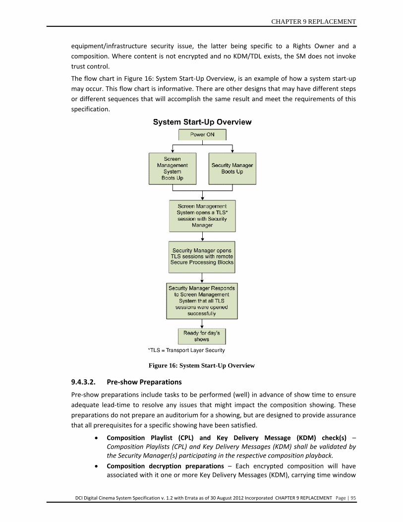
The flow chart in Figure 16: System Start-Up Overview, is an example of how a system start-up may occur. This flow chart is informative. There are other designs that may have different steps or different sequences that will accomplish the same result and meet the requirements of this specification.
Figure 16: System Start-Up Overview
9.4.3.2. Pre-show Preparations
Pre-show preparations include tasks to be performed (well) in advance of show time to ensure adequate lead-time to resolve any issues that might impact the composition showing. These preparations do not prepare an auditorium for a showing, but are designed to provide assurance that all prerequisites for a specific showing have been satisfied.
• Composition Playlist (CPL) and Key Delivery Message (KDM) check(s) – Composition Playlists (CPL) and Key Delivery Messages (KDM) shall be validated by the Security Manager(s) participating in the respective composition playback.
• Composition decryption preparations – Each encrypted composition will have associated with it one or more Key Delivery Messages (KDM), carrying time window
CHAPTER 9 REPLACEMENT
DCI Digital Cinema System Specification v. 1.2 with Errata as of 30 August 2012 Incorporated CHAPTER 9 REPLACEMENT Page | 96
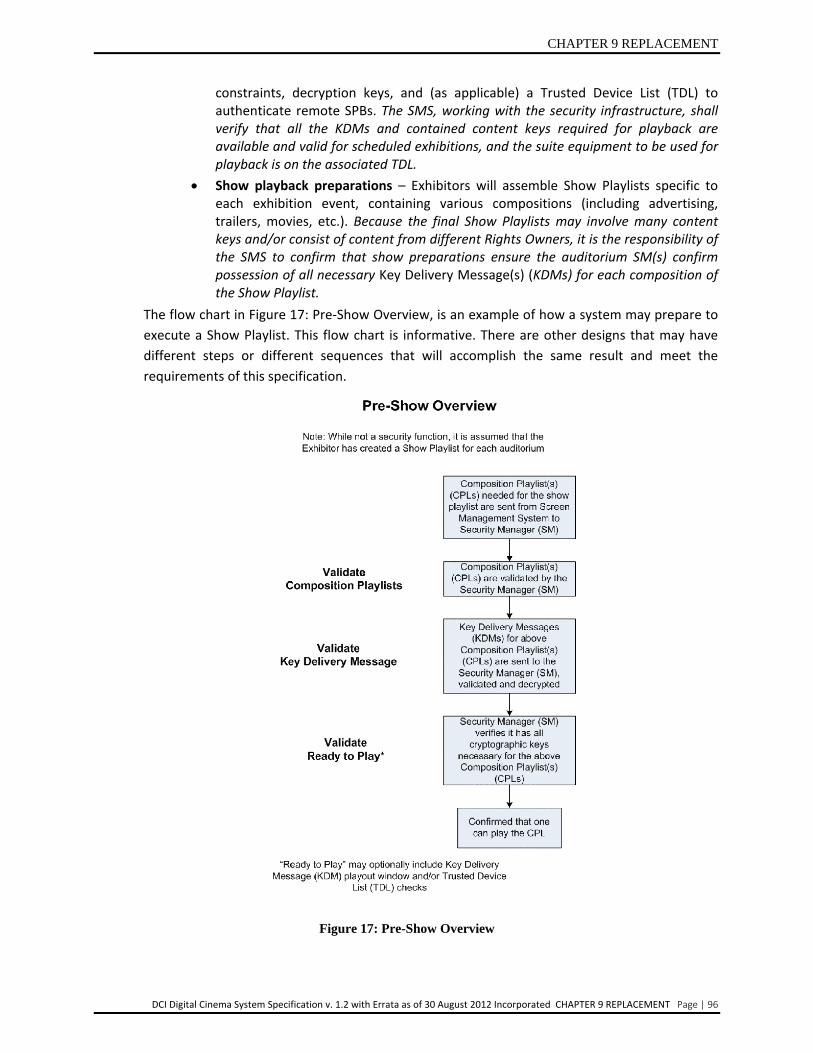
constraints, decryption keys, and (as applicable) a Trusted Device List (TDL) to authenticate remote SPBs. The SMS, working with the security infrastructure, shall verify that all the KDMs and contained content keys required for playback are available and valid for scheduled exhibitions, and the suite equipment to be used for playback is on the associated TDL.
• Show playback preparations – Exhibitors will assemble Show Playlists specific to each exhibition event, containing various compositions (including advertising, trailers, movies, etc.). Because the final Show Playlists may involve many content keys and/or consist of content from different Rights Owners, it is the responsibility of the SMS to confirm that show preparations ensure the auditorium SM(s) confirm possession of all necessary Key Delivery Message(s) (KDMs) for each composition of the Show Playlist.
The flow chart in Figure 17: Pre-Show Overview, is an example of how a system may prepare to execute a Show Playlist. This flow chart is informative. There are other designs that may have different steps or different sequences that will accomplish the same result and meet the requirements of this specification.
Figure 17: Pre-Show Overview

CHAPTER 9 REPLACEMENT
DCI Digital Cinema System Specification v. 1.2 with Errata as of 30 August 2012 Incorporated CHAPTER 9 REPLACEMENT Page | 97
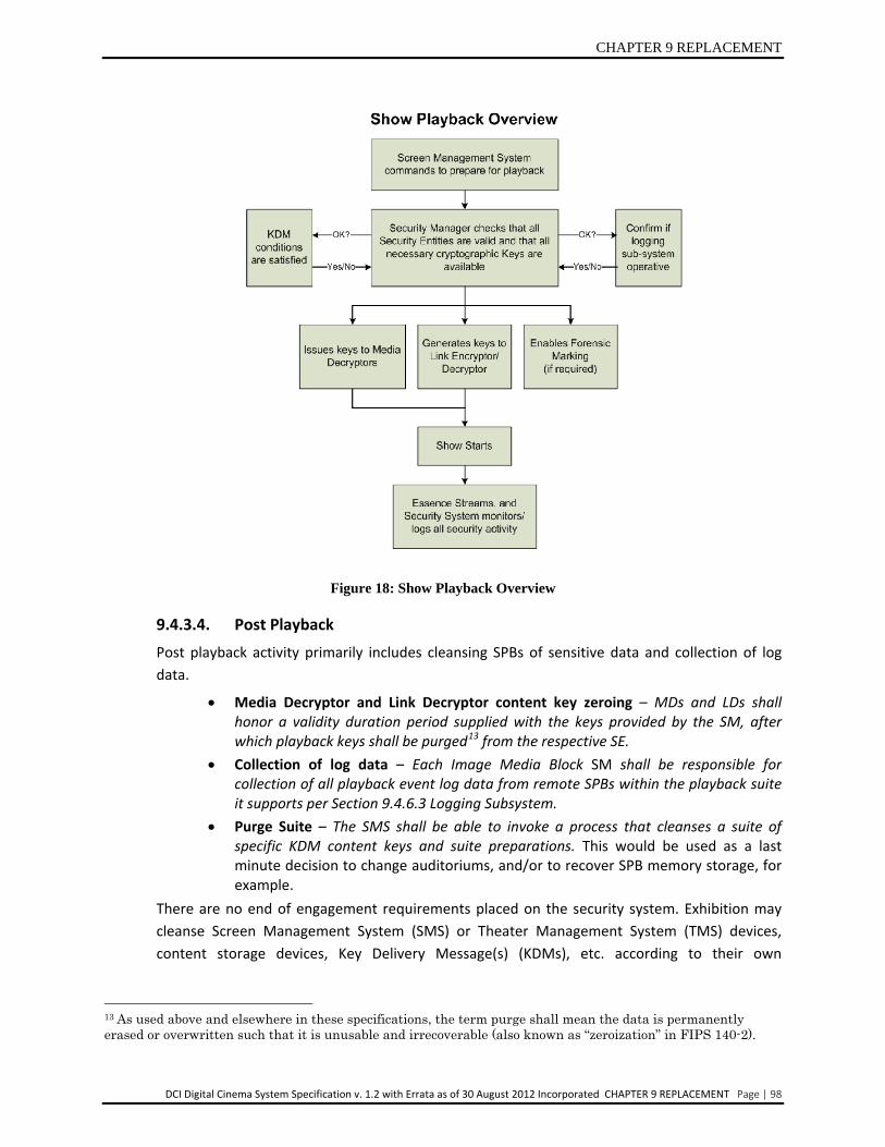
9.4.3.3. Show Playback Show playback processes include auditorium preparations for the playback of a specific Show Playlist, and the actual run-time security functions that include content decryption at the Media Decryptor(s), link encryption/decryption, forensic marking, and recording of log data.
• Equipment preparations – The SMS and SM(s) shall prepare for playback prior to each Show Playlist (SPL) showing. This shall include validation of the authenticity and "trust status" of suite SPBs, and delivery of all necessary KDMs/keys per Section 9.4.3.5 Functions of the Security Manager (SM). Different compositions may have different requirements and the system shall check the SPBs against the TDL for each composition independently.
• Streaming media decryption – Playback of a show consists of a concatenation of compositions that require serial or (separately) parallel decryption. One or more Media Blocks (i.e., for single IMB or Multiple Media Block (MMB) operation) will be involved.
• Link Encryption (LE) and Link Decryption (LD) – If Link Encryption is used, the SM shall support keying of LE and LD Security Entities.
• Forensic Marking – Each MB shall apply Forensic Marking to image and audio data during playback.
• Log data recording – Media Blocks and remote SPBs shall capture log records as specified in Section 9.4.6.3 Logging Subsystem.
The flow chart in Figure 18: Show Playback Overview, is an example of how a system may execute a Show Playlist. This flow chart is informative. There are other designs that may have different steps or different sequences that will accomplish the same result and meet the requirements of this specification.
CHAPTER 9 REPLACEMENT
DCI Digital Cinema System Specification v. 1.2 with Errata as of 30 August 2012 Incorporated CHAPTER 9 REPLACEMENT Page | 98
Figure 18: Show Playback Overview
9.4.3.4. Post Playback Post playback activity primarily includes cleansing SPBs of sensitive data and collection of log data.
• Media Decryptor and Link Decryptor content key zeroing – MDs and LDs shall honor a validity duration period supplied with the keys provided by the SM, after which playback keys shall be purged13 from the respective SE.
• Collection of log data – Each Image Media Block SM shall be responsible for collection of all playback event log data from remote SPBs within the playback suite it supports per Section 9.4.6.3 Logging Subsystem.
• Purge Suite – The SMS shall be able to invoke a process that cleanses a suite of specific KDM content keys and suite preparations. This would be used as a last minute decision to change auditoriums, and/or to recover SPB memory storage, for example.
There are no end of engagement requirements placed on the security system. Exhibition may cleanse Screen Management System (SMS) or Theater Management System (TMS) devices, content storage devices, Key Delivery Message(s) (KDMs), etc. according to their own
13 As used above and elsewhere in these specifications, the term purge shall mean the data is permanently erased or overwritten such that it is unusable and irrecoverable (also known as “zeroization” in FIPS 140-2).

CHAPTER 9 REPLACEMENT
DCI Digital Cinema System Specification v. 1.2 with Errata as of 30 August 2012 Incorporated CHAPTER 9 REPLACEMENT Page | 99
operational needs. Defined security system behavior places controls on Security Data, keys, etc. such that security interests are maintained.
The flow chart in Figure 19: Post Playback Overview, is an example of those items a system performs following a completed Show Playlist. This flow chart is informative. There are other designs that may have different steps or different sequences that will accomplish the same result and meet the requirements of the specification.
Figure 19: Post Playback Overview
9.4.3.5. Functions of the Security Manager (SM)
Auditorium Security Managers (SMs) are responsible for overseeing the security aspects of the auditorium they are assigned to (installed in), inclusive of the Secure Processing Blocks they are responsible for and according to the content essence types they are provided to process. For Multiple Media Block (MMB) situations multiple SMs will be present within an auditorium, and each SM operates independently from other SMs in responding to the auditorium’s Screen Management System (SMS) to enable playback of content. The required SM functions are described below, from the perspective of each SM (i.e., not from the perspective of the auditorium). Depending upon the requirements for any given DCP, it will be recognized that for Multiple Media Block (MMB) auditorium situations the services of any single MB may not completely support playout of the DCP. However, individual compliance to these SM functions will assure playout is securely accomplished by the collective services of the auditorium MBs/SMs.
In listing these functions the approach is that of a reference model for SM behavior, meaning that these specifications do not define required implementation methods. A standards-compliant implementation must, however, have the same input/output behavior as the reference model.
Security Manager (SM) Functions:
1. Receive, store, decrypt and validate Key Delivery Message(s) (KDMs) per the three validity checks of Section 6.1.2 of the KDM specification (SMPTE430-1: D-Cinema Operations - Key Delivery Message). Constrain use of KDM content keys per items 4 and

CHAPTER 9 REPLACEMENT
DCI Digital Cinema System Specification v. 1.2 with Errata as of 30 August 2012 Incorporated CHAPTER 9 REPLACEMENT Page | 100
9 below to the SM's confirmation that one of the certificates in the signer chain of the associated Composition Play List (CPL) has a thumbprint that matches the ContentAuthenticator element of the KDM, per Section 5.2.4 of said KDM specification.
2. Security Manager (SM) KDM usage policy is specified as follows: a. For any given SM, playout within the associated Media Block (MB) shall be
supported by a single KDM(i.e., a playout shall not occur that requires the combination of two or more KDMs). (Note that Multiple Media Block (MMB) operation will require multiple KDMs to support playout across multiple SMs/MBs. Since all KDMs for a given CPL must contain all the content keys for the composition (see Section 9.4.3 Theater Security Operations), depending upon its MB configuration the SM may find more essence keys in the KDM and identified in the CPL than it will use.)
b. For any given composition, playout shall be enabled for any start time that is within the KDM's time window.
c. To avoid end of engagement issues, a show time’s playout may extend beyond the end of the KDM's playout time window, if started within the KDM playout time window, by a maximum of six (6) hours.
d. Excepting the requirements of item 2c above, the SM shall delete any KDM and associated keys for which the playback time window has expired (passed).
3. Reject ETM messages that are not recognized as DCI compliant standardized messages. 4. Validate Composition Playlists (CPL), and log results as a prerequisite to the associated
composition playback. For encrypted content, validation shall be by cross checking that the associated KDM's ContentAuthenticator element matches a certificate thumbprint of one of the certificates in the CPL's signer chain (see item 1 above), and that such certificate indicate only a “Content Signer” (CS) role per Section 5.3.4, “Naming and Roles” of the certificate specification (SMPTE430-2 D-Cinema Operation - Digital Certificate).
5. Process essence (i.e., Track File frame) integrity pack metadata for image and sound during show runtime. Integrity pack deviations (including HMAC, as applicable) detected during playback shall be logged; however, per Section 9.6.1.2 "Digital Rights Management: Security Manager" Table 21, playback should not be prevented or interrupted. For clarity purposes, integrity pack metadata is defined as Track File ID, Frame Sequence and calculated Message Integrity Code (MIC) information to be compared against the reference data contained in the associated CPL. Log information necessary to detect deviations (including restarts) from the actual playback sequence from the Track File ID and reel sequence specified in the CPL as follows: a. Image – Process integrity pack information, with the exception that the frame hash
(HMAC) check is encouraged but optional. b. Audio – Process integrity pack information, including the hash (HMAC). The SM shall
prevent playout of encrypted content for which the image and sound integrity pack metadata is not present per the requirements of Section 5.3.2.1.
The SM shall prevent playout of encrypted content for which the image and sound integrity pack metadata is not present per the requirements of Section 5.3.2.1
6. [This item left blank intentionally.] 7. Perform remote Secure Processing Block (SPB) and Screen Management System (SMS)
authentication through Transport Layer Security (TLS) session establishment, and maintain the certificate lists so collected.

CHAPTER 9 REPLACEMENT
DCI Digital Cinema System Specification v. 1.2 with Errata as of 30 August 2012 Incorporated CHAPTER 9 REPLACEMENT Page | 101
a. Associate certificate lists with TDLs delivered in KDMs per Section 5.2.5 of the KDM specification (SMPTE430-1: D-Cinema Operations - Key Delivery Message) to support the identification of security devices that are trusted/not trusted.
b. Maintain TLS sessions open for not more than 24 hours between complete restarts (i.e., forces periodic fresh TLS keys). Perform proxy mode of authentication for projection systems per Section 9.4.3.6.5.
c. Content owners may optionally allow the SM to automatically assume trust in remote SPBs (i.e., have the SM trust security devices without their certificate information appearing on the TDL). To support this feature, a unique "assume trust" certificate thumbprint is specified as the "SHA-1 of the empty string". The Base64 value of this string shall be "2jmj7l5rSw0yVb/vlWAYkK/YBwk=" for this exclusive use. When the KDM's DeviceList carries exclusively (only) the assume trust thumbprint, the SM shall consider the auditorium suite certificates collected during TLS session establishment as being "on the TDL." In other words, the SM shall act as if the TDL requirement has been satisfied. SM behavior shall otherwise follow all rules of this section. Should the KDM's DeviceList carry any thumbprint in addition to the assume trust thumbprint, the SM shall ignore this part (c) rule. The assume trust thumbprint shall not be used to enable Special Auditorium Situations per item 16 below.
8. Support TLS-protected ITM standards per Section 9.4.5.2 Intra-Theater Message Definitions. ITM functions shall include: a. Maintain TLS sessions with suite SPBs (including the SMS), b. Querying/receiving status of other SPBs external to the SM’s Media Block,c. ITM
usage and operational behavior means with respect to item 8a and item 8b, sufficient to detect any equipment substitutions,
d. Reporting status on CPL playability, suite readiness and other SM and SPB conditions to the SMS,
e. Movement of security (or security related) information (e.g., content keys and LE keys, logging data, secure time).
9. Prepare and issue KDM-borne content keys to Media Decryptors (MD) per the CPL. Constrain use of keys to: a. Confirmation (via QuerySPB command) that TLS connections are operative with
remote SPBs, and that the QuerySPB Response “general response” element indicator is “0” (RRP successful).
b. Usage validity periods of six (6) hours for remote SPBs (in line with the rule of item 2c above).
c. Authenticated and trusted Secure Processing Blocks (SPBs (per item 7 above). The system shall check the SPBs against the TDL for each composition independently.
d. Media Decryptors (MD) within the SM’s SPB (i.e., under no circumstances shall an SM export any KDM-borne essence key from the SM’s SPB).
e. Specific MDs matching the key type IDs as designated by the KDM, per Section 5.2.8 of the KDM specification (SMPTE430-1: D-Cinema Operations - Key Delivery Message).
f. Receipt by the SM of a valid KDM and CPL for the composition being prepared for playback per items 1 and 4 above.
10. Support Link Encryption (LE) keying (if link encryption is used) by:
CHAPTER 9 REPLACEMENT
DCI Digital Cinema System Specification v. 1.2 with Errata as of 30 August 2012 Incorporated CHAPTER 9 REPLACEMENT Page | 102
a. Generating unpredictable keys per Section 9.7.6 Key Generation and Derivation and having a usage validity period on a per-showing basis (i.e., each playout of an encrypted composition requires a new LE key.) which is generated per item 11 below.
b. Transferring LE keys only to an authenticated and trusted (per item 7 above) Link Decryptor Security Entity (SE) function.
c. Support link encryption operational processes for combinations of clear and encrypted content according to Section 9.4.4 Link Encryption.
11. Perform suite playback preparations per items 9 and 10 above for each showing, within 30 minutes prior to show time. Though item 9 above establishes key validity periods of six hours, security equipment integrity checks and suite re-keying shall be executed within 30 minutes prior to each show time.
12. Maintain secure time, including remote SPB time synchronization requirements per Section 9.4.3.7 Theater System Clocks and Trustable Date-Time.
13. Execute log duties per Section 9.4.6.3 Logging Subsystem. 14 Execute Forensic Marking (FM) control operations per Section 9.4.6.2 Forensic Marking
Operations. 15. During all normal operating conditions (including during playback), continuously monitor
and log integrity status of remote SPBs so as to preclude delivery of keys/content to, or playback on, compromised or improperly operating security equipment. To support this requirement the QuerySPB command (see Section 9.4.5. Intra-Theater Communications) shall be issued to each remote SPB at least every 30 seconds whenever TLS sessions are open. Receipt of a QuerySPB response indicating a "security alert" condition shall be indicative of a faulty SPB, and shall prevent or terminate playback per the DRM requirements of Section 9.6.1 Digital Rights Management. Once a show has started, failure of a TLS link shall not cause termination of a show (i.e., QuerySPB commands will not successfully execute, but the show should continue to play if possible).
16. [This item left blank intentionally.] 17. The SM shall be “playout aware”, meaning it shall have real-time knowledge of the
occurrence of playout start and end periods. Secure Processing Block behavior and suite implementations shall permit the SM to prevent or terminate playback upon the occurrence of a suite SPB substitution or addition since the previous suite authentication and/or ITM status query. The SMs shall respond to such a change by immediately purging all content and link encryption keys, terminating and re-establishing: a) TLS sessions (and re-authenticating the suite), and b) suite playability conditions (KDM prerequisites, SPB queries and key loads). Perform the security equipment integrity checks and suite re-keying per item 11 above prior to the next playback.
18. Perform and log all the above functions under the operational (not security) control of the particular SMS designated by the exhibition operator per Section 9.4.2.5 Screen Management System (SMS).
9.4.3.6. Functional Requirements for Secure Processing Block Systems Each type 1 Secure Processing Block (SPB) can be considered an SPB system, since it operates as a collection of SEs. Similarly, the projector also has its associated type 2 SPB, which does not contain SEs, but fulfills security functions as described below. (Secure Processing Block types are defined in Section 9.4.2.2 The Secure Processing Block (SPB).)
This section defines the functions and operational requirements for the following SPB systems:
CHAPTER 9 REPLACEMENT
DCI Digital Cinema System Specification v. 1.2 with Errata as of 30 August 2012 Incorporated CHAPTER 9 REPLACEMENT Page | 103
• Projector Secure Processing Block (SPB) • Link Decryptor Block (LDB) Secure Processing Block (SPB) • Image Media Block (IMB) Secure Processing Block (SPB) • Outboard Media Block (OMB) • LD/LE Device Secure Processing Block (SPB)
In addition to the specific requirements given for SPB systems in this section, all SPB systems shall meet the behavior requirements of Section 9.6.1 Digital Rights Management.
9.4.3.6.1. Normative Requirements: Projector Secure Processing Block
From a security perspective, a projection system consists of the projector Secure Processing Blocks (SPB) type 2 and its companion SPB, which will be either the Link Decryptor Block (LDB) or Image Media Block (IMB). The following are the normative requirements for the projector Secure Processing Block (SPB):
1. The projector’s companion SPB (Link Decryptor Block or Image Media Block) shall be physically inside of, or otherwise mechanically connected to, the projector Secure Processing Block (SPB).
2. The projector and Link Decryptor Block (LDB) Secure Processing Blocks (SPBs) shall be authenticated to the SM. However, authentication does not ensure that the two SPBs are mechanically connected to each other or ensure that an IMB/projector system is mechanically connected. Therefore, an electronic marriage shall take place upon installation of an IMB or LDB projector pair. This physical/electrical connection shall be battery-backed and monitored 24/7 by the companion SPB and, if broken, shall require a re-installation (re-marriage) process. Breaking the marriage shall not zero the projector SPB long term identity keys (RSA private), see item 7 below.
3. Projector maintenance may involve a marriage (or re-marriage) event, or access to the projector SPB or both. To support projector maintenance, the projector SPB may be serviceable, but access is security-sensitive because of the possibility of tampering during service access.
Once a projector is installed, projector SPB access door “open”, access door “close”, “marriage” and “marriage break” events shall be logged, and the “AuthID” token (see Section 9.4.6.3.8 Log Record Information) shall indicate the responsible exhibition party that executed (or supervised) the event(s). Once a projector is installed, all relevant projector SPB events of Section 9.4.6.3 Logging Subsystem shall be logged 24/7 under both powered and un-powered conditions.
To avoid the complexity of retaining its own log records (and the associated need for a clock and battery-backed persistence), the projector SPB shall send projector SBP log event data (i.e., SPBOpen and SPBClose signals per Table 19 “Security Log Event Types and Subtypes”) across the marriage electrical interface for retention by the companion SPB.
4. Projector SPB designs shall not allow physical access to signals running between the companion SPB and the projector SPB without breaking the marriage, in which case a re-installation shall be required and tampering will be observed by the authorized installer (see Section 9.5.2.4 Specific Requirements for Type 2 Secure Processing Blocks).
CHAPTER 9 REPLACEMENT
DCI Digital Cinema System Specification v. 1.2 with Errata as of 30 August 2012 Incorporated CHAPTER 9 REPLACEMENT Page | 104
5. The projector SPB shall accept the decrypted streaming image signal from either the Image Media Block (IMB) or Link Decryptor Block (LDB) SPB and process accordingly.
6. The projector SPB shall provide at least a type 2 image signal path and tamper/access protection container. The physical requirements for a type 2 SPB are given in Section 9.5.2.4 Specific Requirements for Type 2 Secure Processing Blocks.
7. The projector SPB shall include a Secure Silicon host device (see Section 9.5.2. Robustness and Physical Implementations) which shall contain the SPB's digital certificate.
9.4.3.6.2. Normative Requirements: Link Decryptor Block (LDB)
The following requirements are normative where Link Encryption is used: 1. As part of the installation (mechanical connection to projector and electrical
initiation), perform electrical and logical marriage with the projector SPB. Electrical connection integrity between the Link Decryptor Block and the projector SPB shall be monitored 24/7. Should the integrity of the connection be broken, log the event and require a re-installation process before becoming active again.
Breaking of the LDB/projector SPB marriage shall not zero the LDB SPB long-term identity keys (RSA private keys).
2. Perform content link decryption, and pass the decrypted streaming image to the appropriate circuitry inside the projector SPB. Link Decryptor Blocks shall be designed so as to not to perform link decryption functions unless married to a projector SPB.
3. Respond to the Security Manager’s (SM’s) initiatives in establishing a Transport Layer Security (TLS) session and Link Decryptor Block authentication. Maintain this session until commanded to terminate.
4. Link Decryptor Blocks (LDBs) shall not establish security communications with more than one SM at a time.
5. The LDB shall contain a UTC time reference clock which is battery backed and operative for time stamping log events under powered and un-powered conditions. The LDB shall communicate time information with the SM using standardized Intra-Theater Messaging.
6. Respond to SM “status” queries, and other Intra-theater Messages (ITMs) and SM commands as necessary to support SM behavior requirements.
7. Accept and store link decryption keys, and associated parameters, provided by the SM. The LDB shall have the capacity to store at least 16 key/parameter sets.
8. Purge LD keys upon expiration of the SM designated validity period, SM “purge” command, Link Decryptor Block SPB tamper detection, break of projector LDB SPB electrical connection, or change in TLS network parameters suggestive of an attack or equipment substitution.
9. Record security event data for logging under both powered and un-powered conditions. Assemble logged information into standardized log records per Section 9.4.6.3 Logging Subsystem. The LDB shall support all logging functions of the projection system by providing 24/7 log recording support and storage of all log records associated with the projection system.
10. Monitor Link Decryptor Block SPB physical security protection integrity 24/7. In the event of intrusion or other tamper detection, terminate all activity and zero all
CHAPTER 9 REPLACEMENT
DCI Digital Cinema System Specification v. 1.2 with Errata as of 30 August 2012 Incorporated CHAPTER 9 REPLACEMENT Page | 105
Critical Security Parameters (see Section 9.5.2.6 Critical Security Parameters and D-Cinema Security Parameters). Do not purge log records.
9.4.3.6.2.1. Normative Requirements for LD/LE SPB Devices
The following requirements are normative where an SPB that performs link decryption followed by link encryption is used (see 9.4.4.1 Special Auditorium Situations):
1. Within the LD/LE Device's type 1 SPB perimeter, perform link decryption followed by link encryption at the image essence input and output ports. Subject to the constraints of Section 9.4.4.1 “Special Auditorium Situations”, multiple link encryption output ports may be implemented
2. Respond to the Security Manager's (SM's) initiatives in establishing a Transport Layer Security (TLS) session and SPB device authentication. Maintain this session until commanded to terminate.
3. LD/LE SPB Devices shall not establish security communications with more than one SM at a time.
4. LD/LE SPB Devices shall contain a UTC time reference clock that is battery backed and operative for time stamping log events under powered and un-powered conditions. The SPB shall communicate time information with the SM using standardized Intra-Theater Messaging.
5. Respond to SM "status” queries, and other Intra-Theater Messages (ITMs) and SM commands as necessary to support SM behavior requirements.
6. Accept and store LD/LE keys, and associated parameters, provided by the SM. The SPB shall have the capacity to store at least 16 key/parameter sets.
7. Purge LD/LE keys upon expiration of the SM designated validity period, SM "purge” command, SPB tamper detection, or change in TLS network parameters suggestive of an attack or equipment substitution.
8. Record security event data for logging under both powered and un-powered conditions. Assemble logged information into standardized log records per Section 9.4.6.3 Logging Subsystem.
9. Monitor LD/LE SPB Device physical security protection integrity 24/7. In the event of intrusion or other tamper detection, terminate all activity and zero all Critical Security Parameters (see Section 9.5.2.6). Do not purge log records.
9.4.3.6.3. Normative Requirements: Image Media Block (IMB) The following are normative requirements for the Image Media Block:
1. Perform all SM functions as defined under Section 9.4.3.5 Functions of the Security Manager (SM).
2. Monitor IMB SPB physical security protection integrity 24/7. In the event of intrusion or other tamper detection, terminate all activity and zero all Critical Security Parameters (see Section 9.5.2.6). If communication with the SMS is available, issue an alert message. Do not purge log records.
3. When the IMB is integrated with the projector (i.e., is the projector's companion SPB), at the time of installation (mechanical connection to the projector and electrical initiation) the IMB shall perform and thereafter support electrical and logical marriage with the projector SPB per Section 9.4.3.6.1 Normative Requirements: Projector Secure Processing Block. Electrical connection integrity shall
CHAPTER 9 REPLACEMENT
DCI Digital Cinema System Specification v. 1.2 with Errata as of 30 August 2012 Incorporated CHAPTER 9 REPLACEMENT Page | 106
be monitored 24/7, and should the integrity of the connection be broken the IMB shall log the event and require a re-installation process before becoming active again. Breaking of the IMB/projector SPB marriage shall not zero the IMBs long-term identity keys (RSA private keys).
4. Figure 15: Digital Cinema Auditorium Security Implementations of Section 9.4.1 presents the two fundamental security system architectures as auditoriums 1 and 2: an integrated projection system architecture (no link encryption), and a link encryption architecture, respectively. In the first instance the Integrated Media Block (IMB) outputs clear text content. An IMB intended to operate with an integrated projection system shall be designed such that it does not perform any composition decryption functions until integrated and married to a projector SPB. An IMB intended for non- integrated operation shall be designed to not be reconfigurable to operate with an integrated projection system.
5. Perform media decryption for image, audio and subtitle essence. Perform forensic marking for image and audio essence. The IMB may optionally perform the content essence processing functions defined in Section 9.4.3.6.4 “Normative requirements: Outboard Media Block (OMB)”. In such case IMB forensic marking shall implement both embedded and KDM-borne FMID requirements of Section 9.4.6.1.1 “General Requirements.”
6. After image decryption and Forensic Marking (and other non-security plain text functions as appropriate by design), pass the image signal to the projector SPB or link encryption function, as appropriate. In the latter case the image signal shall undergo link encryption per Section 9.4.4 “Link Encryption.” Subject to the constraints of Section 9.4.4.1 “Special Auditorium Situations,” multiple link encryption output ports may be implemented.
7. Record security event data for logging under both powered and un-powered conditions. Sign and assemble logged information into standardized log reports per Section 9.4.6.3 Logging Subsystem. When integrated within a projector as the projector's companion SPB, the IMB shall provide 24/7 log recording support and storage of all log records associated with the projector SPB.
9.4.3.6.4. Normative Requirements: Outboard Media Block (OMB)
The following are the normative requirements for the Outboard Media Block: 1. Perform the following itemized SM functions as defined under Section 9.4.3.5
Functions of the Security Manager (SM): # 1, # 2, # 3, # 4, #5, # 9 (except for sub-items a and c), # 12, # 13, # 14, # 18.
2. Monitor OMB SPB physical security protection integrity 24/7. In the event of intrusion or other tamper detection, terminate all activity and zero all Critical Security Parameters (see Section 9.5.2.6). If communication with the SMS is available, issue an alert message. Do not purge log records.
3. Perform media decryption on encrypted essence, and forensic marking as applicable on essence prior to outputting clear text content from the SPB. OMB forensic marking shall implement both embedded and KDM-borne FMID requirements of Section 9.4.6.1.1 General Requirements.
4. Content essence type(s) are limited to those explicitly listed as follows:
CHAPTER 9 REPLACEMENT
DCI Digital Cinema System Specification v. 1.2 with Errata as of 30 August 2012 Incorporated CHAPTER 9 REPLACEMENT Page | 107
• Object-Based Audio Essence (OBAE) as defined in the Digital Cinema Object-Based Audio Addendum published by Digital Cinema Initiatives, LLC (DCI) on September 9, 2013.
5. Record security event data for logging under both powered and un-powered conditions. Sign and assemble logged information into standardized log reports per Section 9.4.6.3 Logging Subsystem.
9.4.3.6.5. Projector Authentication
Where link encryption is used, authentication of the projection system to the SM is required. The "proxy mode" of authentication is herein defined as the use of the companion LDB and its TLS session to proxy for the projector SPB. Proxy mode authentication of the projection system is accomplished as follows: LDB certificate information is delivered to the SM during the LDB's TLS session initiation handshake. The projector's certificate information is subsequently delivered to the SM using the GetProjCert Standardized Security Message (see Section 9.4.5.2.4 "Request Response Pairs"). For married projection systems that use link encryption, projection system authentication shall be according to proxy mode. The SM shall ensure that both the LDB and projector SPB certificate thumbprints are on the TDL prior to enabling playout. When the SM is the companion SPB (i.e., architectures with no link encryption), the projector's certificate information shall be obtained by the SM directly over the marriage connection. The SM shall ensure that the projector certificate thumbprint is on the TDL prior to enabling playout.
9.4.3.6.6. Permanently Married Implementations
This section assumes that the LDB and IMB are implemented as field replaceable SPB modules. It is not mandatory, however, that they be implemented in this fashion. It is allowed, for example, for the LDB to be permanently married to a projector, and not field replaceable. In such a case where the projector and its companion SPB (LDB or IMB) are not field separable, there is no marriage event, and thus no reason to monitor whether the marriage connection is broken. This relieves the companion SPB from marriage monitoring duties, but does not change the requirement for IMB or LDB equivalent SPB functions, and the projector SPB, to meet the respective SPB type 1 and type 2 physical and logical protection requirements of Section 9.5 Implementation Requirements, and the normative requirements as specified above, except as the latter requirements relate to marriage event and connection monitoring. In the case where the Projector and companion SPB are inseparable, a single Digital Cinema Certificate shall represent both the Projector and its companion SPB (Image Media Block or Link Decryptor Block). For dual certificate implementations this shall be the Security Manager Certificate (see Section 9.5.1 Digital Certificates). Implementations that do not meet the marriage functions, per the normative requirements of this section, shall not permit field replacement of the IMB or LDB security function as appropriate according to which function is the companion SPB to the projector, and shall require the projector SPB and companion SPB system to be replaced in the event of an SPB failure.
CHAPTER 9 REPLACEMENT
DCI Digital Cinema System Specification v. 1.2 with Errata as of 30 August 2012 Incorporated CHAPTER 9 REPLACEMENT Page | 108
A deviation from these requirements shall be considered non-compliant and a “Security Function Failure” (see Section 9.5.5 Compliance Testing). Note: For permanently married implementations where there are no remote SPBs the KDM need not carry Trusted Device List (TDL) information. The KDM syntax requirement that the associated “DeviceList” element not be empty can be satisfied by placing any Digital Cinema certificate thumbprint in this field.
9.4.3.7. Theater System Clocks and Trustable Date-Time
Note: Nothing in this section shall require that the user interfaces of the SMS or TMS use UTC. It is envisioned that these will use local time. To ensure playback times and event log time stamps are time-accurate, means must exist to distribute and maintain proper security system time. Time shall mean UTC (Coordinated Universal Time). See ASN.1 standard syntax for transferring time and date data “GeneralizedTime” and “UTCTime”.
• All security transactions conferring date-time information (e.g., KDM time window) shall be UTC.
Image Media Block (IMB) and Outboard Media Block (OMB) Security Managers shall each be responsible for maintaining secure and trusted time for their respective MBs. Additional security system clock requirements are:
• The Image Media Block (IMB) SM shall be responsible for establishing and maintaining time for the auditorium Equipment Suite it supervises.
• Each IMB and OMB clock shall be set by the MB vendor to within one second of UTC using a reference time standard (such as WWV). The clock shall be tamper-proof and thereafter may not be offset from UTC or otherwise reset.14
• In order to maintain synchronism between auditoriums, Exhibition shall be able to adjust a Security Manager’s time a maximum of +/- six minutes within any calendar year. Time adjustments shall be logged events.
• Remote SPBs type 1 shall have internal UTC time clocks, and maintain time-awareness 24/7 under both powered and un-powered conditions. The IMB Security Manager shall track the time difference between remote SPB clocks and its internal clock by issuance of the "GetTime" standardized security message of Table 15 "Intra-Theater Message Request-Response Pairs" at least once per day.
• The IMB and OMB Security Manager (SM) clocks shall have the following capabilities: Resolution to one second Stability to be accurate +/- 30 seconds/month Date-Time range at least 20 years Battery life of at least 5 years Battery can be changed without losing track of proper time Proper time stamping of log events shall not be interrupted during a clock
battery change process. • Remote SPB clocks shall meet the same capabilities as the SM clock, except the
stability requirements are +/- 60 seconds per month. Exhibition shall be able to adjust a remote SPB's time a maximum of +/- fifteen minutes within any calendar
14 A limited-magnitude adjustable time offset to this clock is described in the subsequent point.
CHAPTER 9 REPLACEMENT
DCI Digital Cinema System Specification v. 1.2 with Errata as of 30 August 2012 Incorporated CHAPTER 9 REPLACEMENT Page | 109
year. Time adjustments shall be logged events.
9.4.4. Link Encryption Link Encryption shall be used at all times (i.e., for encrypted and clear text content) where image content is carried on interconnecting cables, which are exposed (i.e., outside of an SPB) downstream from image media decryption. The Security Manager (SM) shall enforce link encryption operations per the requirements of this section in all applications except for fully integrated architectures (i.e., "Auditorium 1" configuration of Figure 15: Digital Cinema Auditorium Security Implementations).
Where Link Encryption is used (i.e., Auditorium 2 Figure 15: Digital Cinema Auditorium Security Implementations), the Image Media Block (IMB) SM shall provide link encryption keys for use with the Link Encryptor (LE) and Link Decryptor (LD) Security Entities (SE) located within the IMB and Link Decryptor Block (LDB) SPBs respectively. Authentication of the LDB by the IMB SM (see Security Manager and LDB requirements of Section 9.4.3.5 Functions of the Security Manager (SM) and Section 9.4.3.6.2.1 Normative Requirements for LD/LE SPB Devices) shall be performed to ensure that link keys are provided only to legitimate devices which appear on the KDM Trusted Device List (see Section 9.6.2 “Trust” and the Trusted Device List (TDL)). Link Encryption keys shall be delivered to the LDB using the appropriate category 2 standardized security messages of Table 15 Intra-Theater Messages Request-Response Pairs.
In the case of playback of clear text content (as indicated by the CPL), no KDM is required, and in such a case no TDL will exist. Recognizing that combinations of clear text and encrypted content must be accommodated, the following rules define normative Link Encryption functionality:
• In any instance where content is not encrypted and no KDM for this content exists, the SM shall automatically assume “trust” in the LDB and projector SPBs for purposes of keying the LDB and enabling playback for (only) that CPL. All logging processes shall take place normally, recognizing that some logging events (e.g., no logging of content key use) will not be recorded.
• In instances where combinations of encrypted and non-encrypted content constitute a Show Playlist, the SM shall require the LDB and projector to appear on the TDL prior to enabling keying Link Encryption functions and enabling playback for any CPL having encrypted content.
Link Encryption shall be implemented according to RDD 20-2010 SMPTE Registered Disclosure Document: “CineLink 2 Specification.” Link Encryption keys shall be generated according to the requirements of Section 9.7.6 Key Generation and Derivation. Link Encryption keys shall be distributed using the appropriate Standardized Security Messages of 9.4.5.2.4 Request-Response Pairs (and shall not be distributed using in-band techniques). The individual requirements of this specification shall take precedence over RDD 20-2010 as a whole.
It is mandatory that a fresh Link Encryption key be used for each movie showing (i.e., each playout of an encrypted composition requires a new LE key.) Multiple Link Encryption keys may be used for showings, and in such cases, it is encouraged that different LE keys be distinguished by (used according to) the CPL (where different Composition Playlists constitute a showing). In the case where multiple LE keys are used, it will be necessary for the industry to standardize on a single technique to identify which LE key is to be used for which portion(s) of any given showing.

CHAPTER 9 REPLACEMENT
DCI Digital Cinema System Specification v. 1.2 with Errata as of 30 August 2012 Incorporated CHAPTER 9 REPLACEMENT Page | 110
9.4.4.1. Special Auditorium Situations “Special Auditorium Situations” are defined to allow the Image Media Block (IMB) to operate with more than a single projector. Special Auditorium Situations shall be enabled by the following methods:
• IMB with Multiple Link Encryption means the use of (i) more than one remote LDB/projector pair with a single IMB, or (ii) an LD/LE image processor SPB inserted between the IMB and one or more remote LDB/projector pair(s).
• Integrated IMB with Link Encryption means the use of an integrated and married IMB/projector pair, where the IMB also outputs a Link Encrypted image signal to one or more remote LDB/projector pair(s). The IMB shall simultaneously meet all requirements for both integrated and non-integrated projector system implementations.
IMB SMs shall enable Special Auditorium Situations to operate only when the SM receives a KDM whose Trusted Device List (TDL) contains only the identities of the SPBs it is enabling for playback. For IMB with Multiple Link Encryption operation these shall be the remote SPBs identified during TLS authentication (see details below). For Integrated IMB with Link Encryption this additionally includes the identity of the projector to which the IMB is married. This matching is an indication to the SM that Special Auditorium Situations operation has been approved by the content owner.
IMB with Multiple Link Encryption operation or Integrated IMB with Link Encryption operation shall follow all normal (single) Link Encryption requirements of this section, with the following additional requirements:
a. SM behavior shall be designed to identify a Special Auditorium Situation during the auditorium security network TLS session establishment. The digital certificate exchange with remote SPBs shall return the associated certificate roles for each SPB in the auditorium.
b. The SM shall independently authenticate each remote SPB against the TDL using a dedicated TLS session.
c. The SM shall independently key each remote SPB for Link Encryption operation using standardized Intra-Theater (security) Messaging per Section 9.4.5.
d. The SM shall not support the use of more than one LD/LE image processor SPB for any given projector.
e. The Link Encryption stages of the LD/LE image processor configuration may use the same LE key(s). Similarly, the SM may key the multiple LDB/projector configuration using the same LE key for each LDB/projector system.
9.4.5. Intra-Theater Communications This Section discusses requirements for communications necessary to support security functions in each auditorium. Depending upon facility communications network designs, there may be both intra-auditorium as well as theater-wide networks and these may be physically one network. The security system requires and addresses only the intra-auditorium network, over which Intra-Theater (security) Messages (ITM) are employed.
CHAPTER 9 REPLACEMENT
DCI Digital Cinema System Specification v. 1.2 with Errata as of 30 August 2012 Incorporated CHAPTER 9 REPLACEMENT Page | 111
Intra-Theater Message(s) (ITMs) are described for communications between the SMS and SM(s), and between the SM(s) and remote Secure Processing Blocks (SPBs). The Image Media Block (IMB) shall support all ITMs as defined in this section. The Outboard Media Block (OMB) shall only support ITMs between the SMS and OMB (the OMB does not support Link Encryption or authenticate remote SPBs and thus shall not support Auditorium Security Messaging).
9.4.5.1. Transport Layer Security Sessions, End Points and Intra-Theater Messaging
The SM and SMS shall both conduct their intra-theater security messaging under TLS protection (IETF RFC 2246).
All TLS end points shall be within the physical protection perimeter of the associated SPB. No SPB requirements are placed on the SMS.
9.4.5.2. Intra-Theater Message Definitions
This section identifies the set of Intra-Theater Messages standardized by this specification. These are required to support interoperability and normative operational and security behavior of SPB systems.
9.4.5.2.1. Intra-theater Message Hierarchy The following hierarchy for Intra-Theater Messaging (ITM) is defined:
• Transactions – Describe the interactions between exhibition components (Security Entities) and the system state changes that occur as a result of the transaction.
• Request/Response Pairs (RRP) – Describes a single interaction between the SEs. At least one RRP is required to implement a transaction.
• Messages – A data structure that passes between SEs. An RRP consists of a request message and a resultant response message.
A transaction consists of sequences of RRPs, and RRPs are pairings of messages. A transaction is an interaction, or series of interactions (RRPs) that change the state in one or more participating SEs in a consistent manner. Transactions need not be standardized. In assembling transactions, the sequences of RRPs used may vary according to the equipment vendor or facility configuration. Transactions shall be “idempotent” (such a transaction may be repeated without changing its outcome). Thus, if the initiator of a transaction does not receive evidence of satisfactory completion, it may safely initiate the transaction again without fear of unexpected consequences. RRP standards do not apply inside of Secure Processing Blocks (SPBs), however RRP concepts are developed assuming that a Security Entity (SE) will exist logically within a SPB, even if not distinctly in hardware. The SPB is allowed to proxy for any SE (within it) in the support of security messaging.
9.4.5.2.2. Terms and Abbreviations
The following abbreviations and terms are used in this ITM section: • Requester = initiator of an RRP • Responder = answers the RRP • UDP & TCP = IP protocols for delivering blocks of bytes (UDP) or stream of bytes
(TCP)

CHAPTER 9 REPLACEMENT
DCI Digital Cinema System Specification v. 1.2 with Errata as of 30 August 2012 Incorporated CHAPTER 9 REPLACEMENT Page | 112
9.4.5.2.3. General RRP Requirements 1. Only the SMS or SM shall set up Transport Layer Security (TLS) sessions. TLS session
establishment between SMS and SM may be initiated by either party. Except where noted, only the SMS or SM shall initiate RRPs.
2. Security Managers (SMs) shall not communicate with SPBs other than those in its Equipment Suite, and SPBs shall not communicate with SMs other than the one assigned to their suite.
3. During normal operations, remote Secure Processing Blocks (SPBs) shall maintain their TLS communications sessions with the SM open and active at all times.
4. Absence of a response after an RRP is directed to a SPB over an active TLS session represents a network failure or SPB fault condition. Playback shall continue under network failure conditions to the extent possible.
5. Unless otherwise noted, an RRP response is allowed to be busy or an unsupported message type, and such a response shall not be an error event.
6. No broadcast RRP commands shall be used or required. 7. Except where noted, non-TLS security communications shall not be allowed, and
production Digital Cinema security equipment shall have no provisions for performing security functions in a TLS “bypass” mode.
8. RRP protocols shall be synchronous: Each pairing shall be opened and closed before a new RRP is opened between any two devices. Nested transactions (in which one end point must communicate with another end point while the first waits) are allowed.
9. Standardized security messages (Category 2 messages of Table 15) shall use, and have exclusive use of, well-known port 1173 (which has been reserved for SMPTE digital cinema use by the Internet Assigned Numbers Authority [IANA]). Operational messages (Category 1 messages of Table 15) shall not use well-known port 1173, but shall operate under TLS.
10. Equipment suppliers may implement proprietary ITM, however such ITM shall not communicate over well-known port 1173 (i.e., any non-standardized ITM shall use a different port).
11. Equipment suppliers shall define and describe their respective security designs surrounding the use of well-known port 1173 per the requirements of FIPS 140-2 per Section 9.5.2.5 FIPS 140-2 Requirements for Type 1 Secure Processing Blocks.
9.4.5.2.4. Request-Response Pairs (RRP)
Table 15: Intra-theater Message (ITM) Request-Response Pairs (RRP) lists "standardized security messages" (category 2) and suggested "operational messages" (category 1). The following establishes the implementation requirements for these message types:
• Standardized Security Messages - Standardized security messages shall be compliant to SMPTE 430-6 D-Cinema Operations - Auditorium Security Messages, and shall consist only of messages listed as category 2 messages of Table 15: Intra-theater Message (ITM) Request-Response Pairs (RRP). These messages are used between the Image Media Block and remote SPBs, with the IMB as the Requestor (RRP initiator). The security data and related information that is the subject of these messages shall be communicated only via standardized security messages.
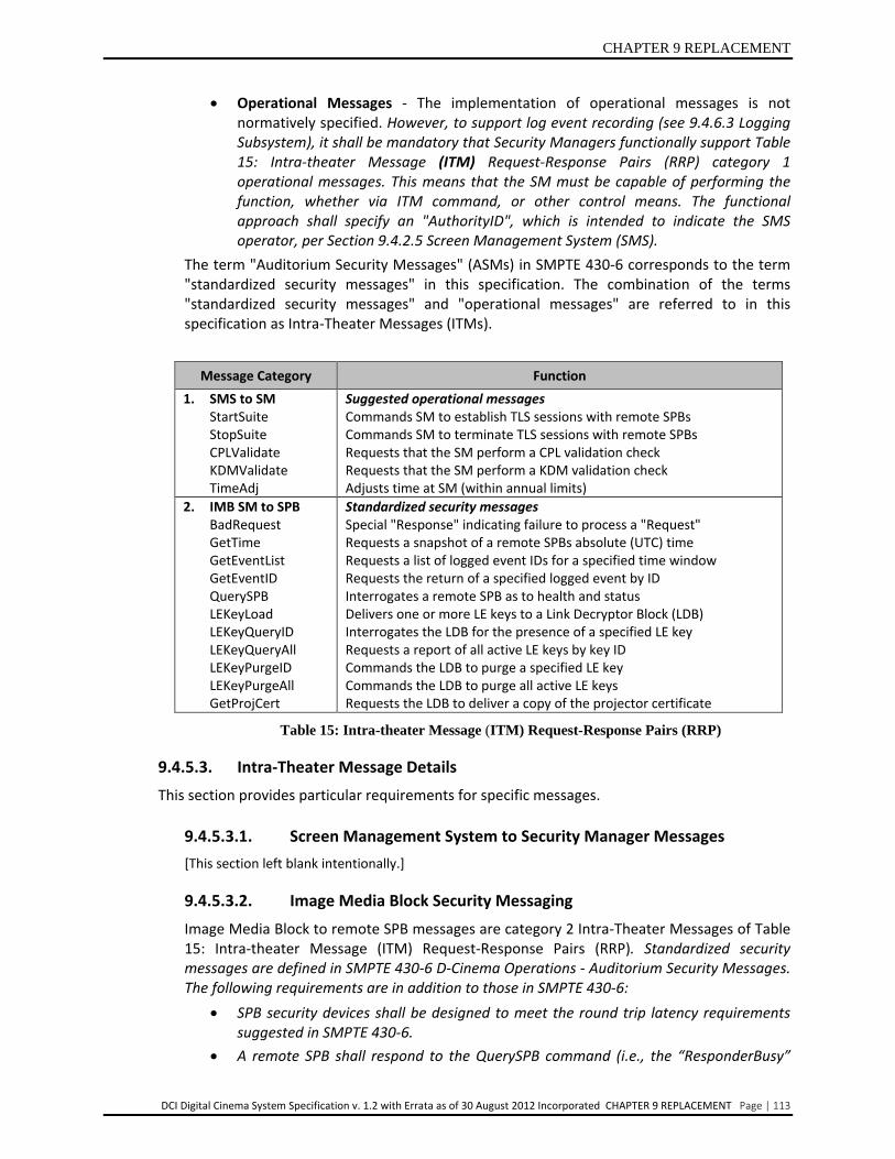
CHAPTER 9 REPLACEMENT
DCI Digital Cinema System Specification v. 1.2 with Errata as of 30 August 2012 Incorporated CHAPTER 9 REPLACEMENT Page | 113
• Operational Messages - The implementation of operational messages is not normatively specified. However, to support log event recording (see 9.4.6.3 Logging Subsystem), it shall be mandatory that Security Managers functionally support Table 15: Intra-theater Message (ITM) Request-Response Pairs (RRP) category 1 operational messages. This means that the SM must be capable of performing the function, whether via ITM command, or other control means. The functional approach shall specify an "AuthorityID", which is intended to indicate the SMS operator, per Section 9.4.2.5 Screen Management System (SMS).
The term "Auditorium Security Messages" (ASMs) in SMPTE 430-6 corresponds to the term "standardized security messages" in this specification. The combination of the terms "standardized security messages" and "operational messages" are referred to in this specification as Intra-Theater Messages (ITMs).
Message Category Function 1. SMS to SM
StartSuite StopSuite CPLValidate KDMValidate TimeAdj
Suggested operational messages Commands SM to establish TLS sessions with remote SPBs Commands SM to terminate TLS sessions with remote SPBs Requests that the SM perform a CPL validation check Requests that the SM perform a KDM validation check Adjusts time at SM (within annual limits)
2. IMB SM to SPB BadRequest GetTime GetEventList GetEventID QuerySPB LEKeyLoad LEKeyQueryID LEKeyQueryAll LEKeyPurgeID LEKeyPurgeAll GetProjCert
Standardized security messages Special "Response" indicating failure to process a "Request" Requests a snapshot of a remote SPBs absolute (UTC) time Requests a list of logged event IDs for a specified time window Requests the return of a specified logged event by ID Interrogates a remote SPB as to health and status Delivers one or more LE keys to a Link Decryptor Block (LDB) Interrogates the LDB for the presence of a specified LE key Requests a report of all active LE keys by key ID Commands the LDB to purge a specified LE key Commands the LDB to purge all active LE keys Requests the LDB to deliver a copy of the projector certificate
Table 15: Intra-theater Message (ITM) Request-Response Pairs (RRP)
9.4.5.3. Intra-Theater Message Details This section provides particular requirements for specific messages.
9.4.5.3.1. Screen Management System to Security Manager Messages [This section left blank intentionally.]
9.4.5.3.2. Image Media Block Security Messaging Image Media Block to remote SPB messages are category 2 Intra-Theater Messages of Table 15: Intra-theater Message (ITM) Request-Response Pairs (RRP). Standardized security messages are defined in SMPTE 430-6 D-Cinema Operations - Auditorium Security Messages. The following requirements are in addition to those in SMPTE 430-6:
• SPB security devices shall be designed to meet the round trip latency requirements suggested in SMPTE 430-6.
• A remote SPB shall respond to the QuerySPB command (i.e., the “ResponderBusy”
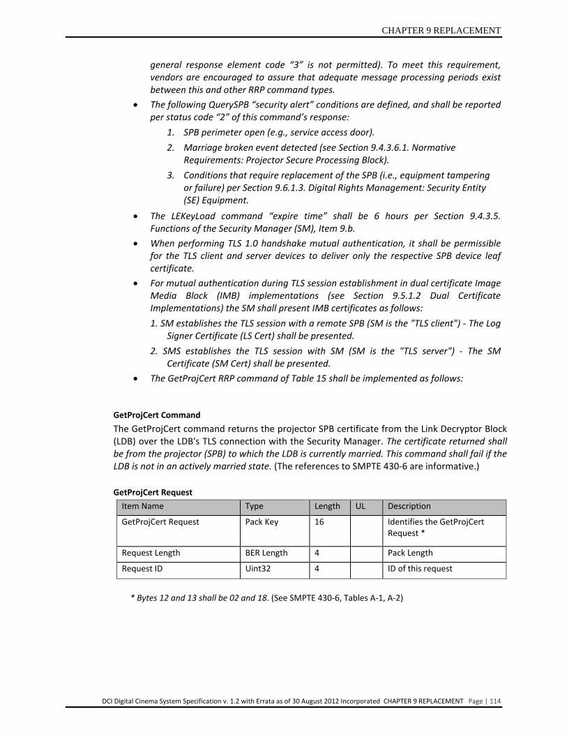
CHAPTER 9 REPLACEMENT
DCI Digital Cinema System Specification v. 1.2 with Errata as of 30 August 2012 Incorporated CHAPTER 9 REPLACEMENT Page | 114
GetProjCert Command The GetProjCert command returns the projector SPB certificate from the Link Decryptor Block (LDB) over the LDB's TLS connection with the Security Manager. The certificate returned shall be from the projector (SPB) to which the LDB is currently married. This command shall fail if the LDB is not in an actively married state. (The references to SMPTE 430-6 are informative.) GetProjCert Request
Item Name Type Length UL Description
GetProjCert Request Pack Key 16 Identifies the GetProjCert Request *
Request Length BER Length 4 Pack Length
Request ID Uint32 4 ID of this request
* Bytes 12 and 13 shall be 02 and 18. (See SMPTE 430-6, Tables A-1, A-2)
general response element code “3” is not permitted). To meet this requirement, vendors are encouraged to assure that adequate message processing periods exist between this and other RRP command types.
• The following QuerySPB “security alert” conditions are defined, and shall be reported per status code “2” of this command’s response:
1. SPB perimeter open (e.g., service access door). 2. Marriage broken event detected (see Section 9.4.3.6.1. Normative
Requirements: Projector Secure Processing Block). 3. Conditions that require replacement of the SPB (i.e., equipment tampering
or failure) per Section 9.6.1.3. Digital Rights Management: Security Entity (SE) Equipment.
• The LEKeyLoad command “expire time” shall be 6 hours per Section 9.4.3.5. Functions of the Security Manager (SM), Item 9.b.
• When performing TLS 1.0 handshake mutual authentication, it shall be permissible for the TLS client and server devices to deliver only the respective SPB device leaf certificate.
• For mutual authentication during TLS session establishment in dual certificate Image Media Block (IMB) implementations (see Section 9.5.1.2 Dual Certificate Implementations) the SM shall present IMB certificates as follows: 1. SM establishes the TLS session with a remote SPB (SM is the "TLS client") - The Log
Signer Certificate (LS Cert) shall be presented. 2. SMS establishes the TLS session with SM (SM is the "TLS server") - The SM
Certificate (SM Cert) shall be presented. • The GetProjCert RRP command of Table 15 shall be implemented as follows:

CHAPTER 9 REPLACEMENT
DCI Digital Cinema System Specification v. 1.2 with Errata as of 30 August 2012 Incorporated CHAPTER 9 REPLACEMENT Page | 115
GetProjCert Response Item Name Type Length UL Description GetProjCert Response Pack Key 16 Identifies
GetProjCert Response * Response Length BER Length 4 Pack Length Request ID Uint32 4 ID of the request for which
this is the response Projector Certificate Data Byte Array Variable DER encoded certificate Response Uint8 1 Response Info **
The length of the certificate is determined from the length of the response. * Bytes 12 and 13 shall be 02 and 19. (See SMPTE 430-6, Tables A-1, A-2) ** Response (see SMPTE 430-6 Section 6.3): 0 - RRP successful 1 - RRP failed 2 - RRP Invalid 3 - ResponderBusy
Table 16: Left Intentionally Blank Table 17: Left Intentionally Blank Table 18: Left Intentionally Blank
9.4.6. Forensics Forensics do not prevent content theft or other compromises, but rather, it provides methods for their detection and investigation. Forensic features deter attackers who are aware that their actions would be logged and/or reported in considerable detail.
Forensic features fall into two classes: Forensic Marking (FM) and logging. Forensic Marking embeds tracking information into content itself, to be carried into subsequent legitimate or stolen copies. Logging creates records of both normal and abnormal events in the Distribution and Exhibition process. During a content theft investigation, both FM and logging information may be combined to establish the details of the security compromise.
Industry terminology for watermarking and Forensic Marking is not consistent. For these security specification purposes, stakeholders have agreed to use the term Forensic Marking for all content marks.
9.4.6.1. Forensic Marking
These specifications require that image and audio Forensic Marking (FM) capability be included in each Image Media Block. The security system identifies content marking devices (e.g., Forensic Marking embedders) as the “FM” Security Entity (SE) type. To support FM processes, standardized Intra-Theater Messaging (ITM) may be used where needed for communications between such SEs and Security Managers (SMs). Such communications and associated FM behavior is outside of this specification. However the requirements of ITM Section 9.4.5 Intra-Theater Communications shall be mandatory where such theater messaging employs the intra-auditorium security network. Forensic Marking does not require interoperability between

CHAPTER 9 REPLACEMENT
DCI Digital Cinema System Specification v. 1.2 with Errata as of 30 August 2012 Incorporated CHAPTER 9 REPLACEMENT Page | 116
detection systems, as the detection operation is usually performed “off line” as part of a security investigation.
Multiple solutions may be qualified and will allow Media Block solutions providers to select the solution of their choice. Candidate providers should meet with individual studios to discuss RAND and technical suitability of their approach.
Note: DCI reserves the right, at some future time, to require a specific Forensic Marking insertion solution for Digital Cinema systems.
At a minimum, Forensic Marking systems are required to meet the following:
9.4.6.1.1. General Requirements
• The Forensic Marking data payload is required to be a minimum of 35 bits and must contain the following information:
o Time stamp every 15 minutes (four per hour), 24 hours per day, 366 days/year the stamp will repeat annually. There are 35,136 time stamps needed, therefore allocate a 16 bit unsigned number (65,536).
o Location (serial number) information, allocated 19 bits (524,000 possible locations/serial numbers)
• All 35-bits are required to be included in each five minute segment. • Forensic Marking insertion is required to be a real-time (i.e., show playback time), in-
line process performed in the associated media block, and is required to have a reasonable computational process.
• Recovery can take up to a 30-minute content sample for positive identification. • Support of a single distribution inventory is required. • Terms and conditions of use are required to be reasonable and non-discriminatory
(RAND). • Detection can be performed by the vendor or the Rights Owner at the Rights Owner’s
premises. • DCI will entertain development of a generic Forensic Mark inserter architecture. Any
FM technology utilizing pre-processing is required to use a generic inserter architecture that meets the criteria outlined below. Additionally, a full understanding of the intellectual property terms and conditions will need to be reached.
o Standardized Metadata Format – Any pre-processing solution is required to be able to utilize a single, industry standardized metadata transport format and a generic inserter solution.
o Title (Composition) Single Inventory – For each composition, the system is required to support the use of a single image or audio FM technology that generates one set of metadata. This metadata is required to be compatible with all deployed compliant generic inserters. At the distributor’s discretion, multiple sets of metadata can be used to mark the same composition.
o Generic Inserter Compatibility – For the initial generic inserter deployment, the generic inserter in final product form is required to be openly demonstrated and independently tested to demonstrate compatibility with a minimum of three independent metadata-based forensic marking solutions.
CHAPTER 9 REPLACEMENT
DCI Digital Cinema System Specification v. 1.2 with Errata as of 30 August 2012 Incorporated CHAPTER 9 REPLACEMENT Page | 117
o Forensic Mark and Generic Inserter Backwards Compatibility – After initial deployment, any subsequent metadata-based FM solutions or generic inserters are required to function correctly with all deployed compliant systems.
o Forensic Mark Pre-Processing Speed – The Forensic Mark processing steps needed to generate and insert metadata are required to be real time or faster and are required to occur in a single pass.
• As a matter of implementation, recognizing business and post-production constraints, it is encouraged that a generic inserter implementation minimizes the metadata payload needed to provide forensic mark data to the generic inserter. A reasonable target would be less than two percent of the compressed image and sound data payload.
• Each instance of a Forensic Marking application shall include a unique 19 bit minimum “location” Forensic Marking Identification (FMID). The FMID value shall be derived in one of two ways as follows:
1. When the KDM’s KeyIdList contains a KeyType element whose value is “FMIK”, the FM application shall use the lower 19 bits of the 128 bit “AES Content Decryption Key” field encrypted in that KDM’s corresponding CipherValue element. There shall only be one such KeyType element found in a KDM.
o The delivered FMID parameter shall be logged by the MB’s SM, and made available per the log report protocol of Section 9.4.6.3 Logging Subsystem. The FMID value shall be logged as an element so named, and included as part of (i.e., in addition to) the KDMKeysReceived Record of SMPTE 430-5 D-Cinema Operations - Security Log Event Class and Constraints for D-Cinema.
o It is the responsibility of KDM creators to coordinate with each other and the industry to ensure the uniqueness of KDM-borne FMIDs.
2. When the KDM carries no such KeyType element, the FMID value shall be derived from an embedded unique parameter associated with the Forensic Marking application. The FMID shall meet the following requirements:
o The embedded Forensic Mark shall be manufactured-in such that the FMID cannot be changed or reprogrammed by any means whatsoever without violation of the SPB’s type-1 perimeter.
o Manufacturers of SPBs containing Forensic Markers shall maintain and make available an accurate, timely database associating each embedded FMID with its associated SPB serial number and digital certificate.
o Forensic Marking licensors shall ensure the uniqueness of FMIDs.
• To support multiple projection situations, it is the responsibility of KDM creators to assure that each participating Forensic Marking application be supplied with the same KDM-borne FMID value. This value and the accompanying Forensic Mark time stamp shall be used to generate an identical Forensic Mark from each projector, each mark being frame-by-frame synchronized between projectors. Time stamps shall be synchronized such that each Forensic Mark time stamp is identical, and each time value increment occurs in synchronism across the participating projectors throughout the playout (SPB clock drift shall not result in different time stamps). The optically combined synchronized Forensic Marks as projected shall meet the same
CHAPTER 9 REPLACEMENT
DCI Digital Cinema System Specification v. 1.2 with Errata as of 30 August 2012 Incorporated CHAPTER 9 REPLACEMENT Page | 118
“general” and “survivability” requirements as defined herein for single projector applications.
9.4.6.1.2. Image/Picture Survivability Requirements
• Image Forensic Marking is required to be visually transparent to the critical viewer in butterfly tests for motion image content.
• Is required to survive video processing attacks, such as digital-to-analog-digital conversions (including multiple D-A/A-D conversions), re-sampling and re-quantization (including dithering and recompression) and common signal enhancements to image contrast and color.
• Is required to survive attacks, including resizing, letterboxing, aperture control, low-pass filtering and anti-aliasing, brick wall filtering, digital video noise reduction filtering, frame-swapping, compression, scaling, cropping, overwriting, the addition of noise and other transformations.
• Is required to survive collusion, the combining of multiple videos in the attempt to make a different fingerprint or to remove it.
• Is required to survive format conversion, the changing of frequencies and spatial resolution among, for example, NTSC, PAL and SECAM, into another and vice versa.
• Is required to survive horizontal and vertical shifting. • Is required to survive arbitrary scaling (aspect ratio is not necessarily constant). • Is required to survive camcorder capture and low bit rate compression (e.g. 500 Kbps
H264, 1.1 Mbps MPEG-1).
9.4.6.1.3. Audio Survivability Requirements
• Audio Forensic Mark is required be inaudible in critical listening A/B tests. • The embedded signal is required to survive multiple Digital/Analog and
Analog/Digital conversions. • Is required to survive radio frequency or infrared transmissions within the theater. • Is required to survive any combination of captured channels. • Is required to survive resampling and down conversion of channels. • Is required to survive time compression/expansion with pitch shift and pitch
preserved. • Is required to survive linear speed changes within 10% and pitch-invariant time
scaling within 4%. • Is required to survive data reduction coding. • Is required to survive nonlinear amplitude compression. • Is required to survive additive or multiplicative noise. • Is required to survive frequency response distortion such as equalization. • Is required to survive addition of echo. • Is required to survive band-pass filtering. • Is required to survive flutter and wow. • Is required to survive overdubbing.

CHAPTER 9 REPLACEMENT
DCI Digital Cinema System Specification v. 1.2 with Errata as of 30 August 2012 Incorporated CHAPTER 9 REPLACEMENT Page | 119
9.4.6.2. Forensic Marking Operations There may be differing circumstances surrounding the desire by a Rights Owner to forensically mark content. To accommodate these variations, it is necessary to be able to independently control the activation of both the audio and the image Forensic Marking (FM). The following rules shall be normative for Forensic Marking operations:
1. The SM shall be solely responsible for control of FM marking processes (i.e., “on/off”), and, subject to item 2 below, command and control of this function shall be only via the KDM per item 3 below.
2. Forensic Marking shall not be applied to non-encrypted audio or image content. If portions of a composition are encrypted and other portions are not, FM shall not be applied to those Track Files that are not encrypted.
3. Forensic Marking shall otherwise be applied to all encrypted picture and audio content, except as follows:
a. The "no FM mark" and "selective audio FM mark" state shall be commanded by the 'ForensicMarkFlagList' element of the KDM.
b. When the KDM 'ForensicMarkFlagList' indicates the "no FM mark" command, the FM device(s) shall enter a full bypass mode, and shall not alter the content essence for the associated encrypted DCP.
c. When the KDM 'ForensicMarkFlagList' indicates the "selective audio FM mark" command, the audio FM device(s) shall not impose, in the associated encrypted DCP, any mark onto audio channels above the channel indicated in the command, per (d) below. This paragraph shall override (b) above if both the "no FM mark" and "selective audio FM mark" commands are present.
d. The "selective audio FM mark" command shall be indicated by the presence of a ForensicMarkFlag element containing a URI of the form: http://www.dcimovies.com/430-1/2006/KDM#mrkflg-audio-disable-above-channel-XX where XX is a value in the set {01, 02, 03, 04, 05, 06, 07, 08, 09, 10, 11, 12, 13, 14, 15, 16 ... 99} and corresponds to a channel identifier within the track, per 382M-2007 table E.1, as wrapped in a Sound Track file of the associated encrypted DCP. URIs of this form shall be used in conjunction with keys of KeyType "MDAK". A KDM shall carry only one such ForensicMarkFlag element.
4. “No FM mark” states shall be capable of being independently commanded for audio or image compositions.
5. When commanded, the “no FM mark” state shall apply to the entire encrypted DCP. The “no FM mark” state shall not apply to any other DCP, even if the other DCP is part of the same showing (i.e., same Show Playlist).
6. [This item left blank intentionally.] 7. [This item left blank intentionally.] 8. The SM and FM Security Entities shall log the presence or absence of audio and image
Forensic Marking for each encrypted DCP. 9. Notwithstanding the exceptions defined in Section 9.4.6.2, all audio essence shall be
forensically marked, up to sixteen channels.

CHAPTER 9 REPLACEMENT
DCI Digital Cinema System Specification v. 1.2 with Errata as of 30 August 2012 Incorporated CHAPTER 9 REPLACEMENT Page | 120
9.4.6.3. Logging Subsystem In the Exhibition environment, the preparations for and execution of a movie showing creates information that has security and forensic implications. The capturing and storage of such information is the responsibility of the logging subsystem. In order to realize a “control lightly/audit tightly” end-to-end security environment, the security system includes a secure logging subsystem.
Cryptographic technology as applied to essence and key delivery, together with agreed upon usage rules provides the “control lightly” characteristics. The function of a logging subsystem is to respond to the “audit tightly” requirement. Logging is therefore observed as a critical component of security, and secure logging information and surrounding processes are subject to the same fundamental cryptographic requirements as the front end control components: cryptographic protection of critical functions and data components related to integrity, data loss, confidentiality and movement.
This section sets the logging subsystem requirements for security log data recording and reporting. The log information data formats and structures to be used in conjunction with these requirements are defined in two SMPTE standards:
• SMPTE 430-4 D-Cinema Operations - Log Record Format Specification for D-Cinema
• SMPTE 430-5 D-Cinema Operations - Security Log Event Class and Constraints for D-Cinema
SMPTE 430-4 defines the general format for log classes for digital cinema. SMPTE 430-5 defines the specific requirements for the security log class. All log requirements and terminology of this section are with respect to the SMPTE 430-5 security events class constraints specification.
Definitions related to logging:
• Log Event – Any event that has security implications or forensic value. Such an event results in the recording of log data.
• Log Data – Security event information that is recorded and stored within the Security Entity (SE), where such an event took place or was observed.
• Log Record – Standardized XML structure representing a discrete logged event.
• Log Report – Standardized XML structure containing one or more log records spanning a continuous sequence in time. The log record content in a report is intended to be organized by class, and may be filtered prior to delivery according to specified criteria (Rights Owner, CPL, etc.).
Following the above definitions, a basic logging process is described:
• Surrounding a showing will be a number of security events that result in logged data. Discrete logged event data shall be placed in an XML structure called a record.
• A number of records are collected in sequence and by class to make up log reports.
• A complete (unfiltered) report is useful for transferring entire sets of log data for archiving or post-processing outside of the security system.
CHAPTER 9 REPLACEMENT
DCI Digital Cinema System Specification v. 1.2 with Errata as of 30 August 2012 Incorporated CHAPTER 9 REPLACEMENT Page | 121
• A “filtered” report is useful for responding to a request for log data according to specified bounds (e.g., report the SE key usage records for CPL(id) for specific date(s) and time(s)).
• Reports may be delivered via the theater network using log messages (Intra-theater Messages), or simply transferred to a physical device (e.g., USB removable flash memory).
9.4.6.3.1. Logging Requirements 1. Logging subsystem implementations shall not affect the ability of Exhibition to
operate their projection systems in a standalone fashion. 2. Security Entities (SE) shall have normative requirements for the specific log data to
be recorded for each record (see Section 9.4.6.3.7 Security Log Reports and Section 9.4.6.3.8 Log Record Information).
3. Log records and reports shall be protected from undetected alteration (integrity and authentication) or deletion (continuity).
4. Log records and reports shall be non-repudiable and traceable back to the source SE device (i.e., where the logged event took place).
5. Log records and reports shall carry proof of authenticity, which does not rely on the trustworthiness of the systems and channels they pass through. Systems or devices which communicate, handle or store log messages (or records) need not be trusted or secure.
6. The content of log records shall be protected from exposure to parties other than the intended recipient (see Section 9.4.6.3.6 Log Filtering).
7. Each Rights Owner shall be able to cryptographically confirm the integrity and continuity of log records and their log data independently of other Rights Owners (see Section 9.4.6.3.6 Log Filtering).
8. Image Media Block SMs shall collect log information from all remote Secure Processing Blocks in the suite it enables at the earliest equipment idle time between scheduled showings. To assure timely collection, TLS sessions shall not be terminated prior to collection of all remote SPB log data, and in no event shall more than 24 hours pass between the recording of log data by a remote SPB and the collection of such data by the IMB Security Manager.
9. The Image Media Block shall internally store at least twelve (12) months of typical log data accumulation, including log data collected from the associated remote SPBs. The OMB shall also internally store at least twelve (12) months of typical log data.
10. Remote Secure Processing Blocks (SPBs) shall have sufficient secure storage to hold log data to accommodate at least two days’ worth of typical operation.
11. Log records stored in SPBs shall be stored in non-volatile memory and not be purgeable. Data shall be over-written beginning with the oldest data as new log data is accumulated. In no event shall remote SPB log records be overwritten prior to them being collected by the SM.
12. An SE shall author its own log records, or utilize the services of a proxy within the same secure SPB.

CHAPTER 9 REPLACEMENT
DCI Digital Cinema System Specification v. 1.2 with Errata as of 30 August 2012 Incorporated CHAPTER 9 REPLACEMENT Page | 122
13. SEs or their SPB proxy shall have an asymmetric identity key pair and Digital Cinema certificate for signing log records. Log records shall be signed only by the Security Manager (SM) providing the log report(s).
14. SEs or their proxy shall time stamp log records, with date/time synchronized with the SM’s secure clock. The accuracy of the time stamp relative to the actual event shall not exceed one (1) second. Accuracy shall mean the latency between the occurrence of the event and the indicated time stamp.
15. SEs or their proxy shall sequence log records with a secure and persistent counter. 16. The Image Media Block and Outboard Media Block Security Managers (SM) shall
each associate (identify) all log records with the SMS under which each operates. 17. Any use of a proxy in the above, shall produce log records compliant to these
requirements.
9.4.6.3.2. Log Record and Report Format Log record and report formats shall be compliant with SMPTE 430-5 D-Cinema Operations – Security Log Event Class and Constraints for D-Cinema.
9.4.6.3.3. Log Signatures and Integrity Controls
Log signatures and integrity controls shall be compliant with SMPTE 430-5 D-Cinema Operations - Security Log Event Class and Constraints for D-Cinema. For dual certificate implementations (see Section 9.5.1.2 Dual Certificate Implementations), the following requirements are in addition to those in SMPTE 430-5:
• The LogReport element shall contain the reportingDevice child element as defined in SMPTE 430-4 "D-Cinema Operations - Log Record Format Specification". The reportingDevice element shall be completed as follows (see SMPTE 433 "D-Cinema - XML Data Types"): In the case that the DeviceIdentifier element contains a UUID, the DeviceCertID element shall also be present and shall contain the certificate thumbprint of the SM Certificate. In the case that the DeviceIdentifier element is a certificate thumbprint, it shall contain the certificate thumbprint of the SM Certificate. In either case the certificate thumbprint of the Log Signer Certificate shall be present in the AdditionalID element, encoded as an XML Schema ds:DigestValueType type.
• Log records shall be signed per the requirements of SMPTE 430-5 section 6.2 "Log Record Authentication and Chaining" using the device's Log Signer Certificate.
9.4.6.3.4. Security of Log Record Sequencing Log record sequencing shall be compliant with SMPTE 430-5 D-Cinema Operations - Security Log Event Class and Constraints for D-Cinema.
9.4.6.3.5. Log Upload Protocol over Theater Networks Auditorium suites using Link Encryption shall transfer log records from remote Secure Processing Blocks (SPB) to that auditorium's Image Media Block (IMB) SM using the GetEventList and GetEventID standardized security messages of Table 15 "Intra-Theater Message Request-Response Pairs" Per Section 9.4.3.7 Theater System Clocks and Trustable Date-Time, the Security Manager collects UTC time-stamped reports from remote SPBs via the GetTime standardized security

CHAPTER 9 REPLACEMENT
DCI Digital Cinema System Specification v. 1.2 with Errata as of 30 August 2012 Incorporated CHAPTER 9 REPLACEMENT Page | 123
message. The SM shall use the GetTime information to calculate the difference between true time (the SM's time) and time in the remote SPB, and remove the difference in reporting remote SPB event data. The reporting (export) of log information from the IMB shall be by XML structure that is compliant with SMPTE 430-5 D-Cinema Operations - Security Log Event Class and Constraints for D-Cinema.
9.4.6.3.6. Log Filtering
Log record and/or report filtering processes shall be compliant with SMPTE 430-5 D-Cinema Operations - Security Log Event Class and Constraints for D-Cinema. For distribution of log information, it may be necessary to filter log content so that log reports can be generated that supply log record content selectively to the appropriate recipients. The location(s) where log data filtering takes place (e.g., in the Image Media Block (IMB), Outboard Media Block (OMB) or in external theater-controlled devices or processes) is an implementation decision.
9.4.6.3.7. Security Log Reports Media Block Security Managers shall provide (export) log event information in the form of log reports (not log records) as defined in SMPTE 430-5 D-Cinema Operation - Security Log Event Class and Constraints for D-Cinema. The EventID (see SMPTE 430-4 D-Cinema Operations - Log Record Format Specifications) shall be a single, invariant value that uniquely identifies each logged event. For avoidance of doubt, for a given event the EventID shall be the same value each time it appears in a log report.
9.4.6.3.8. Log Record Information The logging subsystem shall follow the requirements for specific log data to be recorded as defined in SMPTE 430-5 D-Cinema Operations - Security Log Event Class and Constraints for D-Cinema. SMPTE 430-5 defines the following data types for the "Security Class" category of log information: EventType - Identifies a log record as being associated with one of a Playout, Validation, Key, ASM or Operations event. EventSubType - Specifies what information is to be logged for each Event Sub Type record. Each Secure Processing Block (SPB) type shall log the Event Sub Type records as shown in Table 19 Security Log Event Types and Subtypes.

CHAPTER 9 REPLACEMENT
DCI Digital Cinema System Specification v. 1.2 with Errata as of 30 August 2012 Incorporated CHAPTER 9 REPLACEMENT Page | 124
IMB OMB LDB LD/LE SPB Proj. SPB
Playout Event Sub Types FrameSequencePlayed X X CPLStart X X CPLEnd X X PlayoutComplete X X
Validation Event Sub Types CPLCheck X X Key Event Sub Types KDMKeysReceived X X KDMDeleted X X
ASM Event Sub Types LinkOpened X X X LinkClosed X X X LinkException X X X LogTransfer X X X KeyTransfer X X X
Operations Event Sub Types
SPBOpen X15
SPBClose X15
SPBMarriage X 16 X
SPBDivorce X 16 X
SPBShutdown X X X X
SPBStartup X X X X SPBClockAdjust 17 X X X X
SPBSoftware X X X X
SPBSecurityAlert X X X X
Table 19 Security Log Event Types and Subtypes
In addition to the requirements specified in SMPTE 430-5, the following shall be normative for DCI compliance:
• SPBs shall log each of the "Exception" events identified in the EventSubType Record
15 The SPBOpen and SPBClosed event types shall be detected by the projector SPB, and logged and reported by the projector’s companion SPB. 16 Applicable when no Link Encryption is used. 17 Applicable if the SPB has a clock that is adjustable.
CHAPTER 9 REPLACEMENT
DCI Digital Cinema System Specification v. 1.2 with Errata as of 30 August 2012 Incorporated CHAPTER 9 REPLACEMENT Page | 125
descriptions for the applicable Event Sub Type records per Table 19. The SPB shall record the appropriate Exception record(s) as specified in the SMPTE 430-5 EventSubType definitions.
o Recorded Exception token(s) shall include those that prevent an EventSubType from occurring. (For example, LinkOpened and FrameSequencePlayed EventSubTypes define Exceptions that prevent the link from opening or playout from occurring.)
o For the CPLCheck and KDMKeysReceived EventSubTypes, SMPTE 430-5 requires certain values from the input document to be recorded as parameters of the log record. In the case that an exception is recorded for these EventSubTypes, syntactically recognizable data items in the input document shall be recorded. (For example, when a KDMFormatError is recorded because the KDM's signing certificate has expired but the document is otherwise valid, the KDM's MessageId shall be present in the log record.)
• The SPBSecurityAlert Operations EventSubType shall be recorded for conditions that require replacement of the SPB (i.e., equipment tampering or failure) per Section 9.6.1.3 Digital Rights Management: Security Entity Equipment.
• The AuthID token for the Playout Event Sub Type events shall carry the value indicated by the SMS AuthorityID per Section 9.4.2.5 Screen Management System. Per section 9.4.2.6 Projection Systems, the AuthID token for the Operations Event Sub Type events shall indicate the identity of the authority figure responsible for the event.
9.4.6.3.9. FIPS 140-2 Audit Mechanism Requirements FIPS 140-2 requirements (see Section 9.5.2.5 FIPS 140-2 Requirements for Type 1 Secure Processing Blocks) require audit (logging) mechanisms for certain modifiable operating system environments for cryptographic modules. These specifications restrict the SPB operating environment to non-modifiable modes of implementation. Thus there are no additional FIPS 140-2 related logging requirements for Exhibition security devices for normal Digital Cinema operations. Logging requirements for SPB firmware code changes shall be implemented per Section 9.5.2.7 SPB Firmware Modifications. These device-change log records shall be accessible using the log record specifications as given in this section.
9.4.6.3.10. Logging Failures
The secure logging subsystem is required to be operable as a prerequisite to playback. Security Managers (SMs) shall not enable for playback (i.e., key) any suite for which it has not collected log records from Secure Processing Blocks (SPBs) per Section 9.4.6.3.1 Logging Requirements item (8), or if there is any indication that a next playback will not record and report log records as required. Behavior of security devices (SPB or SE) shall be specified and designed to immediately terminate operation, and require replacement, upon any failure of its secure logging operation. Resident log records, in failed SPBs and SEs shall not be purgeable except by authorized repair centers, which are capable of securely recovering such log records.

CHAPTER 9 REPLACEMENT
DCI Digital Cinema System Specification v. 1.2 with Errata as of 30 August 2012 Incorporated CHAPTER 9 REPLACEMENT Page | 126
9.5. Implementation Requirements
9.5.1. Digital Certificates Digital certificates are the means by which the Security Manager (SM) identifies other security devices. They are also used to sign security log records and in establishing Transport Layer Security (TLS) connections. This specification originally required each Secure Processing Block (SPB) to carry a single digital certificate to support each of these requirements. However, in some circumstances (e.g., new equipment designs and/or upgrades) evolving Federal Information Processing Standards (FIPS) have imposed the need for use of a second digital certificate within Media Blocks. (FIPS requirements are addressed in Sections 9.5.2 Robustness and Physical Implementations and 9.7 Essence Encryption and Cryptography.)
To maintain compliance with FIPS requirements, this specification now includes requirements for both single and dual IMB certificate use. Equipment vendors shall solicit FIPS expertise for guidance as to which approach is required for their implementation.
All Digital Cinema certificates shall use the X.509, Version 3 ITU standard (see [ITU-T Recommendation X.509 (1997 E): Information Technology – Open Systems Interconnection – The Directory: Authentication Framework, June 1997, and RFC3280]). Detailed specifications for Digital Cinema digital certificates are given in Section 9.8. Except as otherwise specified below, the requirements for all digital certificates (i.e. both single and dual use implementations) shall be the same.
9.5.1.1. Single Certificate Implementations
Single certificate implementations shall employ one Digital Cinema certificate in each Secure Processing Block (SPB). The requirements for use of a single SPB certificate are provided in the appropriate sections of this specification.
The identity of a device shall be represented by its certificate. The make and model of each certificated device shall be carried in the assigned certificate, and the serial number and device role(s) (see below) shall in particular be carried in the Common Name (CN) field of the assigned certificate. The make, model and serial number of each certificated device shall be placed on the exterior of said device in a manner that is easily read by a human.
Each SPB shall enumerate the security functions of the SPB according to SMPTE 430-2 D-Cinema Operations – Digital Certificate, section 5.3.4 Naming and Roles. For purposes of efficiency, SE types shall be minimally designated according the following roles:
• Image Media Block (IMB) – SM • Image Media Block with Link Encryptor – SM LE • KDM-borne FMID capable IMB – SM FM • KDM-borne FMID capable IMB with OBAE – SM OBAE • KDM-borne FMID capable IMB with LE – SM FM LE • KDM-borne FMID capable IMB with OBAE & LE – SM OBAE LE • Outboard Media Block with OBAE processor – OBAE • Link Decryptor Block – LD

CHAPTER 9 REPLACEMENT
DCI Digital Cinema System Specification v. 1.2 with Errata as of 30 August 2012 Incorporated CHAPTER 9 REPLACEMENT Page | 127
• Image Processor – LD LE • Projector to be married – PR • Projector permanently married to an IMB – PR SM • Projector permanently married to an LDB – PR LD
Notes: • The designation of other roles is optional. • This specification requires that MBs which process OBAE essence be KDM-
borne FMID-capable (see Section 9.4.3.6, Functional Requirements for SPB Systems).
9.5.1.2. Dual Certificate Implementations Dual (two) certificates are used only with the Image Media Block (IMB) and Outboard Media Block (OMB), and no other SPB types are affected. Dual certificate implementations split the utility of digital certificates between the two certificates. Dual certificate utility shall be as follows:
• Security Manager Certificate (SM Cert) – The SM Cert shall be used according to the same requirements as those for the above Section 9.5.1.1 Single Certificate Implementation, except for those functions specified for the below Log Signer Certificate. The SM Cert shall be the certificate associated with the identity of the Media Block and shall be the target of Key Delivery Messages (KDM).
• Log Signer Certificate (LS Cert) – The LS Cert shall be used to 1) sign security log records per the requirements of Section 9.4.6.3.3. “Log Signatures and Integrity Controls” and 2) perform TLS session establishment functions per the requirements of 9.4.5.3.2 “Image Media Block Security Messaging.” Details of these requirements are provided in the noted sections.
The Log Signer Certificate shall enumerate roles only as follows:
• LS – Log Signer; all implementations • LS LE – Log Signer for IMB with Link Encryptor
In addition to the above, dual certificate implementations require Digital Cinema certificate validation rules that may not be reflected in the current SMPTE digital cinema specification (see DCSS Section 9.8, SMPTE 430-2: “D-Cinema Operations – Digital Certificate”). The affected validation rule is driven by the “Key Usage” constraints as given in Table 2 of SMPTE 430-2 (“Field Constraints for Digital Cinema Certificates”), which is then reflected in validation rule # 6 of section 6.2 “Validation Rules”. For dual certificate implementations validation rule # 6 shall be as stated in SMPTE 430-2 for single certificate implementations, except as follows:
• SM Cert – The DigitalSignature flag shall not be set. • LS Cert – The KeyEncipherment flag shall not be set.
9.5.2. Robustness and Physical Implementations •
This security system protects Digital Cinema content during transport and storage through the use of secret keys. Key secrecy is maintained in normal operations by cryptographic techniques dependent upon other secret keys. The physical protection afforded secret keys, and the content itself once decrypted, determine the robustness of the security implementation.
CHAPTER 9 REPLACEMENT
DCI Digital Cinema System Specification v. 1.2 with Errata as of 30 August 2012 Incorporated CHAPTER 9 REPLACEMENT Page | 128
Robustness is required for all modes of operation, both normal and abnormal. Robustness is a function of the quality of the implementation of security devices, Exhibition operational procedures, and the security system itself.
9.5.2.1. Device Perimeter Definitions
Security equipment designs must provide physical perimeters around secrets not cryptographically protected. The following definitions explain terminology used for tamper protection of physical perimeters. Specific tamper requirements for SPB types 1 and 2 are given in subsequent Sections of 9.5.2. • Tamper evident – Penetration of the security perimeter results in permanent alterations
to the equipment that are apparent upon inspection. This is the least robust perimeter, since it only reveals an attack after-the-fact, and depends on a specific inspection activity.
• Tamper resistant – The security perimeter is difficult to penetrate successfully. Compromise of effective tamper resistant designs requires the attacker to use extreme care and/or expensive tooling to expose secrets without physically destroying them and the surrounding perimeter(s).
• Tamper detecting and responsive – The security perimeter and/or access openings are actively monitored. Penetration of the security perimeter triggers erasure of the protected secrets.
9.5.2.2. Physical Security of Sensitive Data
Sensitive data critical to the security of the Secure Processing Block (SPB) or SE (e.g., private keys, LE/LD or content keys) is generically referred to as a Critical Security Parameter (see Section 9.5.2.6 Critical Security Parameters and D-Cinema Security Parameters). CSPs and plain text content essence shall be physically protected by Secure Silicon and/or Secure Processing Blocks as described below: • Secure Silicon – Sensitive data contained within a Secure Silicon integrated circuit (IC)
can only be compromised by a physical attack on the IC. All type 1 and type 2 Secure Processing Blocks (SPB) shall contain a Secure Silicon IC compliant to the following requirements: a. Secure Silicon integrated circuits used for Digital Cinema security applications
shall meet FIPS 140-2 level 3 area five (physical security) requirements as defined for “single-chip cryptographic modules” (no other FIPS 140-2 area requirements are mandated).
b. Other than as part of the manufacturing process, SPB private keys used for device identity (see section 9.5.1 “Digital Certificates”) shall not exist outside of the Secure Silicon IC. For purposes of clarity, this means that (1) private keys (whether encrypted or not) shall not be moved or copied from Secure Silicon, and (2) the CipherValue element(s) of the KDM’s AuthenticatedPrivate element shall be decrypted by and within the Secure Silicon IC.
c. Decrypted (plain text) content image keys may be moved from the Secure Silicon IC for purposes of decrypting image essence during playout only. They shall at all other times be contained within the Secure Silicon IC, or be stored off- chip in an encrypted fashion per the requirements of Section 9.7.4 “Protection of Content Keys”.
• Secure Processing Block (SPB) Hardware Module – Sensitive data will only be exposed by penetration of a physical barrier, which surrounds the electronics.
CHAPTER 9 REPLACEMENT
DCI Digital Cinema System Specification v. 1.2 with Errata as of 30 August 2012 Incorporated CHAPTER 9 REPLACEMENT Page | 129
a. All Secure Processing Block (SPB) module designs shall implement hardware module perimeter protection that prevents access to internal circuitry and detects opening of the module perimeter. Further protection of keys and clear text content should use techniques such as burying sensitive traces, applying tamper resistant integrated circuit coverings, and tamper responsive circuitry. Detailed SPB type 1 and SPB type 2 physical protection requirements are defined below in Section 9.5.2.4 Specific Requirements for Type 2 Secure Processing Blocks and Section 9.5.2.5 FIPS 140-2 Requirements for Type 1 Secure Processing Blocks.
b. Other than the SMS, no Security Entity (SE) shall exist outside the protection of a SPB type 1.
• Software – Protection implemented in software can be compromised through modifications to the software, inspection of memory, or monitoring of bus signals. a. Software protection methods shall not be used to protect Critical Security
Parameter or content essence.
9.5.2.3. Repair and Renewal
The following address restrictions on repair and renewal of Secure Processing Blocks (SPBs) and associated cryptographic parameters: • Type 1 SPBs may be field replaceable (as an entire SPB module) by Exhibition, but shall
not be field serviceable (e.g., SPB type 1 maintenance access doors shall not be open-able in the field).
• The secure silicon device, contained within a SPB type 2, shall not be field serviceable, but may be field replaceable. It shall not be accessible during normal SPB type 2 operation or non-security-related servicing.
• Repair and renewal processes for an SPB type 1 and SPB type 2 shall be performed under the supervision of the security equipment vendor. Maintenance of the SPB type 2 (projector) is permitted for non-security components accessible via maintenance openings.
• All type 1 SPBs shall be issued a new private/public key pair and certificate upon any repair or renewal process that requires opening of the SPB perimeter. (Note that Section 9.7.6 precludes maintaining records of private key information.)
Repair and renewal is limited to failed devices, or devices which have lost or zeroed their secrets (e.g., private keys or digital certificates). Such maintenance does not effect the device’s FIPS 140-2 certification or compliance, as long as Section 9.5.2.5 FIPS 140-2 Requirements for Type 1 Secure Processing Blocks requirements are met. Requirements for firmware changes to SPBs are given in Section 9.5.2.7 SPB Firmware Modifications.
9.5.2.4. Specific Requirements for Type 2 Secure Processing Blocks
The SPB type 2 container has been defined specifically for protection of image essence exiting either a Link Decryptor Block or Image Media Block (companion SPBs to the projector SPB) and entering the projector. The purpose of this SPB is to protect the image essence signal as far as practical, recognizing that “all the way to light” production is probably not possible. It is also preferable not to impose formal FIPS 140-2 requirements on this SPB, as the security and signal flow functions are relatively simple. Requirements for projection systems were defined in Section 9.4.3.6.1 “Normative Requirements: Projection Systems.” As explained there, the type 2 SPB – also referred to as a

CHAPTER 9 REPLACEMENT
DCI Digital Cinema System Specification v. 1.2 with Errata as of 30 August 2012 Incorporated CHAPTER 9 REPLACEMENT Page | 130
projector SPB – is permitted to be opened for maintenance. To assure adequate protection of signals and circuits within the projector SPB, the following address physical requirements, and are in addition to those of section 9.4.3.6.1: • The projector SPB shall be designed for two types of access: “security servicing” and “non-
security servicing.” Security servicing is defined as having access to the companion SPB’s output image essence signal and/or the projector SPB access opening detection circuits and associated signals.
For non-security servicing (i.e., maintenance), the above signals / circuits shall not be accessible via the SPB’s maintenance door opening(s). In other words, there shall be a partition that separates security-related signals/circuits from the non-security related maintenance accessible areas, and access to security related areas shall not be possible without causing permanent and easily visible damage.
Security servicing shall be performed only under the supervision of the projector manufacturer per Section 9.5.2.3 Repair and Renewal.
• Projector SPB access doors or panels shall be lockable using pick-resistant mechanical locks employing physical or logical keys, or shall be protected with tamper-evident seals (e.g., evidence tape or holographic seals).
• Protection from external probing of security-sensitive signals (i.e., image essence and access opening/detecting circuits and signals) shall be provided by assuring barriers exist to prevent access to such signals via ventilation holes or other openings.
In summary, the projector SPB physical perimeter provides for maintenance access and access door opening detection, and the internal design enables access for non-security related servicing. Exhibition visual inspection is relied upon to detect physical abuse that might allow compromise of, or access to, decrypted image essence.
9.5.2.5. FIPS 140-2 Requirements for Type 1 Secure Processing Blocks Robustness requirements for Digital Cinema Secure Processing Blocks (SPBs) shall follow the guidelines of the Federal Information Processing Standards [FIPS PUB 140-2]18. A summary of these requirements is shown in the table below.
FIPS 140-2 specifies eleven areas for evaluation against a rating, which shall be performed by US government recognized independent laboratories.
All SPB type 1 shall meet and be certified for the requirements of FIPS 140-2 Level 3 in all areas except those subject to the following exceptions or additional notes (the Nr indicators refer to the table items by row):
• Nr 2 – Logical data port separation requirements shall be supported by the use of Transport Layer Security (TLS) protection on well known port 1173 as defined in Section 9.4.5.2.3 General RRP Requirements.
• Nr 6 – The software operating environment of Secure Processing Blocks (SPBs) shall be restricted to the Limited Operational Environment. This eliminates the requirements for Common Criteria (CC) and Evaluation Assurance Level (EAL)
18 Readers unfamiliar with [FIPS PUB 140-2] will need to refer to the standards text to fully understand the table and exceptions.
CHAPTER 9 REPLACEMENT
DCI Digital Cinema System Specification v. 1.2 with Errata as of 30 August 2012 Incorporated CHAPTER 9 REPLACEMENT Page | 131
testing, and any additional FIPS140-2-specific logging/audit processes other than those specified in Section 9.5.2.7 SPB Firmware Modifications for firmware modifications.
• Nr 7 – Section 9.7 Essence Encryption and Cryptography of these Digital Cinema requirements shall supersede any conflicts with Nr 7.
• Nr 8 – Secure Processing Blocks (SPBs) shall only be required to meet Security Level 2 business use A FCC class requirements.
• Nr 10 – Design Assurance requirements may meet Security Level 2 requirements. • Nr 1 and Nr 11 – Vendor-specified Security Policy specifications shall be in alignment
with and fully support the requirements of this Digital Cinema specification, in addition to vendor-specific policies.

CHAPTER 9 REPLACEMENT
DCI Digital Cinema System Specification v. 1.2 with Errata as of 30 August 2012 Incorporated CHAPTER 9 REPLACEMENT Page | 132
Nr Section Security Level 1 Security Level 2 Security Level 3 Security Level 4 1 Cryptographic
Module Specification
Specification of cryptographic module, cryptographic boundary, Approved algorithms, and Approved modes of operation. Description of cryptographic module, including all hardware, software, and firmware components. Statement of module security policy.
2 Cryptographic Module Ports And Interfaces
Required and optional interfaces. Specification of all interfaces and of all input and output data paths.
Data ports for unprotected critical security parameters logically separated from other data ports.
3 Roles, Services And Authentication
Logical separation of required and optional roles and services.
Role-based or identity-based operator authentication.
Identity-based operator authentication.
4 Finite State Model
Specification of finite state model. Required states and optional states. State transition diagram and specification of state transitions.
5 Physical Security Production grade equipment.
Locks or tamper evidence.
Tamper detection and response for covers and doors.
Tamper detect & response. EFP and EFT.
6 Operational Environment
Single operator. Executable code. Approved integrity technique.
Referenced PPs evaluated at EAL2 with discretionary access control mechanisms and auditing.
Referenced PPs plus trusted path evaluated at EAL3 plus security policy modeling.
Referenced PPs plus trusted path evaluated at EAL4.
7 Cryptographic Key Management
Key management mechanisms: random number and key generation, key establishment, key distribution, key entry/output, key storage, & key zeroization.
Secret and private keys established using manual methods may be entered or output in plaintext form.
Secret and private keys established using manual methods shall be entered or output encrypted or with split knowledge procedures.
8 EMI/EMC 47 CFR FCC Part 15. Subpart B, Class A (Business use). Applicable FCC requirements (for radio).
47 CFR FCC Part 15. Subpart B, Class B (Home use).
9 Self-Tests Power-up tests: cryptographic algorithm tests, software/firmware integrity tests, critical functions tests. Conditional tests.
Statistical RNG tests. Callable on demand
Statistical RNG tests performed at power-up.
10 Design Assurance Configuration management (CM). Secure installation and generation. Design and policy correspondence. Guidance documents.
CM system. Secure distribution. Functional specification.
High-level language implementation.
Formal model. Detailed explanations (informal proofs). Pre/post conditions.
-- Mitigation of Other Attacks
Specification of mitigation of attacks for which no testable requirements are currently available.
Table 20: Summary of FIPS 140-2 Security Requirements19
19 From Section 4 of [FIPS PUB 140-2]
Table 20 does not reflect the most current FIPS 140-2 table, and shall be considered informative (refer to FIPS 140-2 publications for the most current version of this table).
CHAPTER 9 REPLACEMENT
DCI Digital Cinema System Specification v. 1.2 with Errata as of 30 August 2012 Incorporated CHAPTER 9 REPLACEMENT Page | 133
FIPS 140-2 level 3 devices provide physical and logical protection of their parameters and functions 24/7 and shall be able to respond to attacks under both powered and un-powered conditions. This means that if a type 1 SPB requires a power source to accomplish tamper detection and response, it must zeroize its Critical Security Parameters (CSPs) prior to any situation arising where such power source may not be available. By way of example, if a type 1 SPB is in storage and relying upon a battery for tamper detection and response, it must self-destruct prior to a battery depletion condition which would not support proper tamper detection and/or response.
9.5.2.6. Critical Security Parameters and D-Cinema Security Parameters
A requirement of FIPS-140-2 is to list the Critical Security Parameters (CSP) that are important for the security of Digital Cinema cryptographic module(s) (Secure Processing Block) and its functions. The following CSPs shall receive Secure Processing Block (SPB) type 1 protection, whenever they exist outside of their originally encrypted state.
1. Device Private Keys – RSA private key that devices use to prove their identity and facilitate secure Transport Layer Security (TLS) communications.
2. Content Encryption Keys – KDM AES keys that protect content. 3. Content Integrity Keys – HMAC-SHA-1 keys that protect the integrity of compressed content
(integrity pack check parameters). 4. [This item left blank intentionally.] 5. Link Encryption Keys – Keys that protect the privacy and integrity of uncompressed content
for link encryption. 6. Transport Layer Security (TLS) secrets – These are transient keys/parameters used or
generated in support of TLS and Intra-Theater Messaging (ITM). (TLS secrets associated with the SMS end point of the SMS-SM TLS connection are not considered CSPs.)
The following items are not considered FIPS 140-2 CSPs, but are considered D-Cinema Security Parameters, and shall at all times be protected by a type 1 SPB perimeter (except where log data is extracted per Section 9.4.6.3).
1. Watermarking or Fingerprinting command and control – Any of the parameters or keys used in a particular Forensic Marking process.
2. Logged Data – All log event data and associated parameters constituting a log record or report.
9.5.2.7. SPB Firmware Modifications
The Limited Operational Environment operating system requirement of FIPS 140-2 Section 9.5.2.5 FIPS 140-2 Requirements for Type 1 Secure Processing Blocks restricts SPBs type 1 and the secure silicon chip of SPB type 2 from having their operating system or firmware modified in the field. The following defines the requirements for making firmware20 changes to these security devices. FIPS 140-2 constrained devices shall:
20 The term firmware shall mean all operating system, software, firmware or ROM based code within the SPB type 1 SPB type 2 silicon chip.

CHAPTER 9 REPLACEMENT
DCI Digital Cinema System Specification v. 1.2 with Errata as of 30 August 2012 Incorporated CHAPTER 9 REPLACEMENT Page | 134
• Be designed such that their firmware cannot be modified without the knowledge and permission of the original manufacturer.
• Require a Digital Cinema compliant certificate that authenticates and confirms the identity of the authority figure responsible for making a firmware change, and shall include time/date and version number information associated with any firmware change, in addition to the authority figure.
• Not undergo firmware changes without informing potentially affected information bases that support Digital Cinema equipment operations (e.g., databases used by stakeholders for facility lists, KDM and TDL creation), and the owner of the device.
• Log the firmware change event by meeting FIPS 140-2 Operational Environment (row 6 of Table 20: Summary of FIPS 140-2 Security Requirements) audit/recording requirements of the Operating System Requirements subsection Security Level 3, except that Common Criteria (CC) and Evaluation Assurance Level (EAL) certification mandates shall not be required. The requirements for FIPS Level 3 audit/recording are encouraged but shall be optional.
• Enable the extraction of the above firmware change related log records using standard log record messages per Section 9.4.6.3 Logging Subsystem. For the delivery of these log records, it shall be mandatory that the records be signed.
• Follow FIPS 140-2 certification body change notification requirements regarding modifications to security devices. Undergo re-certification if required.
9.5.3. Screen Management System (SMS) There are no physical constraints or requirements imposed on the SMS by the security system (i.e., no SPB requirements); however, the SMS implementation shall not otherwise weaken or effect the security operations of other Security Entities or SPBs.
9.5.4. Subtitle Processing See Section 9.7.3 Subtitle Encryption.
9.5.5. Compliance Testing Compliance Testing is the process of qualifying Secure Processing Blocks (SPBs) and their Security Entities for use in Digital Cinema systems. All SPBs shall be subject to qualifying criteria in the following areas:
• Compliance to Intra-Theater Messaging (ITM) specifications – The SPB and internal logical SEs shall interpret and respond to the standard ITM message set according to the appropriate Section 9.4.5.2.4 Request-Response Pairs (RRP) category as specified herein.
• Image Media Blocks (IMB) and Outboard Media Blocks (OMB) shall support compliance with standardized Extra-Theater Messaging (ETM) specifications, in addition to the above compliance requirement for ITMs.
• Security Managers and Secure Processing Block systems shall meet the applicable functional requirements as specified in Sections 9.4.3.5 Functions of the Security Manager (SM) and

CHAPTER 9 REPLACEMENT
DCI Digital Cinema System Specification v. 1.2 with Errata as of 30 August 2012 Incorporated CHAPTER 9 REPLACEMENT Page | 135
9.4.3.6 Functional Requirements for Secure Processing Block Systems, respectively. • Compliance to SPB physical and logical requirements – Each SPB shall be evaluated against
physical and logical requirements based on the SPB type per Section 9.5.2 Robustness and Physical Implementations, including FIPS 140-2 requirements as applicable.
Device vendors shall issue Digital Cinema certificates only to devices that comply with this specification.
A device that does not meet all of the above criteria shall not be installed in a DCI compliant Digital Cinema system. A device that does not continue to meet all the above criteria shall be declared a Security Function Failure, and shall be taken out of service until repaired.
9.5.6. Communications Robustness The following are required for the exhibition of content and security communications, and communications networks:
• Theater networks shall protect security system(s) from the threat of external and internal network-borne attacks by the use of appropriate firewalls. At a minimum, each auditorium shall have such firewall protection for any communications interface(s) connecting to the intra-auditorium security network. In particular, such firewall protection shall prevent (filter) communications to or from any well-known port 1173, other than directly between security equipment within a single auditorium.
• Digital Cinema security messages and content shall not be carried over a wireless network, but shall be carried over wire or optical cables.
• The portions of the network used to carry any security messages or content shall be logically or physically separated from any wireless network device. At a minimum, a properly configured firewall shall separate the wired network that carries security messages or content from any wireless network operated at the same facility.
• The network cabling or cabling trough should not be publicly accessible on the premises.
9.6. Security Features and Trust Management This section describes the standardized Digital Cinema security operational features, and how “trust” is communicated and enforced to ensure security features are reliably executed. A security policy is what results once the variables that develop, from the overall security system design and implementation, are constrained according to desired operational characteristics. An open architecture security system should not dictate any specific policy, but enable stakeholders to agree on one more policies that support business needs. Once policy has been decided, it can be described operationally as the security feature set.
9.6.1. Digital Rights Management This section identifies various features and functions that describe the operation of the security system. For each auditorium, the security system consists of three types of components involved in Digital Rights Management (DRM):
1) The Screen Management System (SMS)
2) The Security Manager(s) (SM)
3) The associated security equipment (e.g., Media Block(s), Link Decryption Block)
CHAPTER 9 REPLACEMENT
DCI Digital Cinema System Specification v. 1.2 with Errata as of 30 August 2012 Incorporated CHAPTER 9 REPLACEMENT Page | 136
The last two components have access to, and process, Digital Cinema security information (secrets), such as content keys or plain text content. They are the primary subject of these security specifications. The Screen Management System does not have access to such secrets. But because the Screen Management System initiates security-related activity, it is considered a participant in security events.
The basic business philosophy is to “control lightly, audit tightly.” Per this philosophy, a movie will fail to playback only under four circumstances:
1) Wrong location ) (see Table 21: Examples of Security Manager Events)
2) Wrong date and time (outside the engagement window) (see Table 21: Examples of Security Manager Events)
3) Unauthorized device (equipment is not accepted by the content owner) (see Table 21: Examples of Security Manager Events)
4) Failure of, or tampering, with security equipment (see Table 22: Examples of Failure or Tampering of Security Equipment)
Compliance to security system logging requirements ensures that all events having security implications will generate associated log records that are stored in the Media Block(s). These log records can be accessed by the exhibitor’s Screen Management System, and reports can be provided to appropriate distributors under contractual obligations.
All three types of security system components (Screen Management System, Security Manager, security equipment) have defined roles and responsibilities (e.g., to perform their security functions and generate log records), and overall security depends upon their proper operation. The descriptions below detail the three types of security system components. Included in the Security Manager and security equipment description are tables showing possible security system operational scenarios and how the system responds to a particular issue.
The tables are also designed to be informative to parties interested in understanding business issues in relation to the Digital Cinema security system. It shows that the security system’s reach is limited to only those areas necessary for ensuring persistent protection of content and security data (keys), enabling content to play within a designated time window, and the provisioning of reliable log data (see Table 21: Examples of Security Manager Events and Table 22: Examples of Failure or Tampering of Security Equipment).
9.6.1.1. Digital Rights Management: Screen Management System
The Screen Management System is responsible for managing Exhibition functions such as showtime movie playback, and is under the control of the Exhibitor. The Screen Management System manages playback functions via the Security Manager(s), however the Security Manager is at all times in control of and responsible for security functions and events. The full compliment of Exhibition operational events therefore consists of those under the control of the Security Manager(s) and those under the control of the Screen Management System.

CHAPTER 9 REPLACEMENT
DCI Digital Cinema System Specification v. 1.2 with Errata as of 30 August 2012 Incorporated CHAPTER 9 REPLACEMENT Page | 137
9.6.1.2. Digital Rights Management: Security Manager (SM) The Security Manager is the executor of Digital Rights Management for the Media Block that contains it. In addition, the Image Media Block (IMB) is also responsible for each Secure Processing Block (SPB) in the associated Equipment Suite. Security Managers control content keys and the delivery of such keys to the appropriate Security Entities (SE) to enable playback of encrypted content. Keys are considered active for the business defined play period. Subject to security equipment authentication, proper operation, and integrity checks (see Section 9.4.3 Theater Security Operations), the Security Manager exercises no control over playback, other than content key delivery during the valid play period. Under private business negotiations, a Distributor may provide keys for selected or all Security Managers (i.e., projectors) in a complex.
Item, Observation or Issue Approach
Authorized auditorium KDM (keys) is sent to authorized auditorium SM
Engagement Play-out Window KDM contains designated key use time/date window
Only known & trusted devices are enabled SM authenticates equipment prior to key delivery
Modified Movie File At playback, SM checks and logs movie against CPL
Table 21: Examples of Security Manager Events
The above table depicts events related to the Security Manager and the system’s behavior. A film will not play-out if there is a failure in any of the items in rows 1, 2 and 3 due to wrong location (row 1), wrong date/time (row 2), or the attempted use of an unauthorized device (row 3). In the event of modification in a movie file (row 4), the file should be replaced, but there are no Security System controls preventing an Exhibitor from playing-out a modified file. This event, like all security events, will be logged.
9.6.1.3. Digital Rights Management: Security Entity (SE) Equipment Security Entity equipment must perform to specified standards and function as designed. The Security Manager will continuously test for proper Security Entity identification (authentication), operation and physical integrity (tampering). Content playback is restricted to passing all security tests at all times.
Item, Observation or Issue Approach
Security equipment tampering or failure A tampered or failed device is non-functional until replaced
Auditorium (intra-suite) Security Network Network must be operative to initiate playback
Table 22: Examples of Failure or Tampering of Security Equipment
The above table depicts tampering or failure of security equipment. Security equipment that has been tampered with or is malfunctioning (row 1) shall not continue operation and must be replaced before playback can commence (or continue). An example of malfunctioning security

CHAPTER 9 REPLACEMENT
DCI Digital Cinema System Specification v. 1.2 with Errata as of 30 August 2012 Incorporated CHAPTER 9 REPLACEMENT Page | 138
equipment is a Media Block that no longer performs one of its security functions (e.g., decryption, Forensic Marking, logging). If the auditorium security network is inoperative (row 2), playback cannot start. However, the security system will not cause playback to stop upon failure of the network during a show.
9.6.2. “Trust” and the Trusted Device List (TDL) In a “trust” relationship, it is said “A trusts B regarding X”. More specifically, the relying party A believes that B will behave in certain predictable ways under a certain range of conditions. This behavior-based definition can apply both to business relationships and to the more formalized regime of standardized security devices. And in fact, a useful Digital Cinema trust system must bridge the former to the latter.
When a Distributor trusts a piece of equipment, his level of confidence in its behavior is based on several factors such as those in Table
Factor Root of Trust
1 Robust equipment design Manufacturer and certification organization
2 Reliable manufacturing process Manufacturer
3 Properly installed Installer and organization operating device
4 Properly maintained (e.g., required firmware or security updates)
Organization operating device, manufacturer and certification organization
5 Properly managed (configured, inspected and operated in accordance with expectations during operational life)
Organization operating device
6 Has not been tampered with before or after installation Organization operating device, certification organization
Table 23: Factors Supporting Trust in a Security Device
Protecting the content keys under a full range of potential situations can be a complex task, representing a set of behaviors involving rules and policy that meet the requirements of these specifications and (optionally) the particular business relationship. To simplify trust issues for the Digital Cinema environment, the TDL approach to equipment trust communications has been defined. In this approach, Rights Owners will indicate their approval of specific trusted equipment to be used in conjunction with an engagement by placing the identification of trusted equipment (Secure Processing Blocks and projectors) into the Key Delivery Messages (KDMs) that are sent to Security Managers. Security Managers will trust and accept devices so listed for all security functions subject to the device’s certificate declared roles (see Section 9.5.1 Digital Certificates)
The content of TDLs (e.g., facility-wide, auditorium-specific, inclusive of spares) shall be according to business party agreement, and is out of scope of these specifications.
9.6.2.1. Trust Domains The SM Security Domain is represented by the collection of security devices associated with a single SM that work together to perform a security function. In this system, the SM Security

CHAPTER 9 REPLACEMENT
DCI Digital Cinema System Specification v. 1.2 with Errata as of 30 August 2012 Incorporated CHAPTER 9 REPLACEMENT Page | 139
Domain and its Trust Domain21 are equal, and in the theater these domains are a single auditorium equipment suite. Multiple trust domains are typically used (chained) together to achieve overall security management objectives (e.g., distributing content keys from post-production to Distribution and Exhibition via multiple KDMs).
The SM functions as an anchor for a given Trust Domain. For convenience, this specification uses descriptors such as Distributor SM, Auditorium SM, etc., but it will be recognized that the security system does not mandate any particular topology for Security Managers (SMs) other than requiring that the Image Media Block contain a Security Manager.
The security system must be sufficiently flexible to support complex groupings and relationships between the Rights Owners, Distributors and Exhibitors. Trust Domains represent the essence of these relationships. The required flexibility is achieved through trust communications that supports the existence of simultaneous multiple overlapping domains, as opposed to force-fitting them into a single domain. In practice, this is implemented via the Digital Certificate chains and TDL that is part of the KDM. Digital Certificate chaining and TDL management is out of scope of these standards.
9.6.2.2. Authenticating Secure Processing Blocks & Linking Trust Through Certificates
A Digital Cinema Certificate is a declaration by a trusted organization, such as a manufacturer, that the security device is a particular make and model and is certified (i.e., found compliant to this specification) to perform identified DC roles (e.g., perform Image or Sound Decryption or provide SPB physical protection functions). The certificate is cryptographically bound to the security device it represents, in such a way that the authenticity of the device is easy to verify. The Certificate is also cryptographically bound to the entity that issued it. This latter binding can be authenticated by knowing and trusting another certificate, that of the certificate issuing entity, called the issuing authority or Certificate Authority. Certificates of issuing authorities are called root certificates.
The design of the certificate includes a technique called chaining, which is an elegant and cryptographically strong method of linking certificates back to the root certificate owned by its issuing authority. Thus, where required an entity can authenticate end entity leaf certificates by knowing just the (set of) root certificates it needs.
The use of certificates to authenticate Secure Processing Blocks (SPB) or Security Entities (SEs) prevents the theft of content by substituting a rogue device for a legitimate Secure Processing Block (SPB) or Security Entity (SE) The security system requires (only) Image Media Block Security Managers to perform authentication functions, permitting the SM to safely extend trust to encompass those SPBs and SEs, thus forming its trust domain.
9.6.2.3. Identity vs. “Trust” In the theater, the SM uses certificates for two primary functions: 1) authenticating a Secure Processing Block’s (SPB’s) identity and roles, and 2) establishing the secure Transport Layer
21 Trust Domain areas also exist for post-production and distribution, but are out of scope.

CHAPTER 9 REPLACEMENT
DCI Digital Cinema System Specification v. 1.2 with Errata as of 30 August 2012 Incorporated CHAPTER 9 REPLACEMENT Page | 140
Security (TLS) session for Intra-Theater Messaging communications with that Secure Processing Block (SPB). These two functions are performed simultaneously when the SM and Secure Processing Block (SPB) set up their Transport Layer Security (TLS) session, during which, the Secure Processing Block (SPB) presents its certificate chain to the SM. This process opens secure communications between security devices in each auditorium suite, and allows the SM to identify suite equipment.
However, decisions that the SM makes regarding its “trust” in accepting the remote Secure Processing Blocks (SPBs) as capable of playing content (receiving content keys, etc.) is independent of the above identity/authentication process. Trust decisions are made on a Rights Owner by Rights Owner basis, and communicated via the TDL in the KDM (see Section 9.4.3.1 Transport Layer Security (TLS) Establishment and Secure Processing Block (SPB) Authentication and Section 9.4.3.5 Functions of the Security Manager (SM)).
9.6.2.4. Revocation and Renewal of Trust The use of TDLs in the KDM allows a simple and effective way for Distributors to communicate trust in exhibition equipment to the responsible Security Managers. However, the source (database) of equipment lists, from which TDL information is derived must be managed with respect to revocation and renewal issues per Table 23: Factors Supporting Trust in a Security Device, above.
In routine operation, trusted equipment remains trusted indefinitely. However there may be situations in which trust in a security device needs to be terminated or restored. Controlling change in trust relationships is an important aspect of trust management.
Database references for TDL creation must be managed with respect to trust issues. However, these are outside the scope of this specification.
9.7. Essence Encryption and Cryptography The security system employs widely used and rigorously tested ciphers for use in Digital Cinema. The following are requirements pertaining to Digital Cinema applications for ciphers and associated security parameters.
9.7.1. Content Transport Content security is transport agnostic, and can be accomplished by either electronic or physical means. Other than as authorized and intended by Rights Owners (e.g., to support Distribution practices or requirements), content shall only be decrypted at playback time at the exhibition site under the policy of the SM.
9.7.2. Image and Sound Encryption The AES cipher, operating in CBC mode with a 128 bit key, shall be used for Digital Cinema content encryption. See [FIPS-197 “Advanced Encryption Standard (AES)” November 26, 2001. FIPS-197] and Section 5.3.2MXF Track File Encryption, for MXF track file encryption details.
The content Rights Owner shall determine which, if any, of the essence types in the composition are encrypted for distribution.
CHAPTER 9 REPLACEMENT
DCI Digital Cinema System Specification v. 1.2 with Errata as of 30 August 2012 Incorporated CHAPTER 9 REPLACEMENT Page | 141
9.7.3. Subtitle Encryption Subtitle encryption shall comply with the SMPTE published standard "SMPTE 429-5 D-Cinema Packaging - Timed Text Track File".
Subtitle encryption is directed primarily against interception during transport, and cryptographic protection within the theater is not required. For example, plaintext subtitle content may be transmitted from a server device to a projection unit. It is preferred, but not required, that subtitle content be maintained in encrypted form except during playback.
9.7.4. Protection of Content Keys The RSA Public Key Cipher (with 2048-bit key) shall be used to protect keys for distribution. This is accomplished by the requirements of the Key Delivery Message.
The above RSA asymmetric protection, AES (with 128-bit keys) or TDES (with 112-bit key) symmetric ciphers, may be used to protect the storage of keys once decrypted from the KDM within a Media Block (e.g., where off-secure-chip memory is used for key caching within a Media Decryptor, for example).
9.7.5. Integrity Check Codes FIPS requirements may obsolete or replace certain older cryptographic technologies or standards, rendering them unacceptable for use. The requirements of this section shall be superseded by the FIPS 140-2 or FIPS 140-3 requirements in effect as of the date of FIPS compliance testing and certification per Section 9.5.5 Compliance Testing. Equipment suppliers are cautioned to take into consideration NIST and FIPS transition timing and FIPS validation lead times.
Data integrity signatures (hash values) shall be generated/calculated according to the PKCS-1 Digital Signature Standard, as specified in [IETF RFC 3447 (RSA and SHA-256)]. All signatures shall use SHA-256. Digital Certificates in X.509v3 format as constrained according to Section 9.8., shall be used to authenticate signatures. Signature element definitions and other signature details are available in the specification for each signed data structure.
Cryptographic data integrity checksums shall be ensured according to the HMAC-SHA-1 algorithm, as specified in [FIPS PUB 198a “The Keyed-Hash Message Authentication Code.”]
9.7.6. Key Generation and Derivation Asymmetric keys (RSA keys) shall be generated as specified in [IETF RFC 3447]. Symmetric key generation shall be per ANSI X9.31. FIPS requirements may obsolete or replace certain older cryptographic technologies or standards, rendering them unacceptable for use. The requirements of this paragraph shall be superseded by the FIPS 140-2 or FIPS 140-3 requirements in effect as of the date of FIPS compliance testing and certification per Section 9.5.5 Compliance Testing. Equipment suppliers are cautioned to take into consideration NIST and FIPS transition timing and FIPS validation lead times.
A vendor that pre-loads an RSA private key into a device (e.g., secure silicon per Section 9.5.2.2 Physical Security of Sensitive Data) shall ensure that these pre-loaded keys are unique to each device made by that vendor. The vendor shall not keep any record of the preloaded private keys, though
CHAPTER 9 REPLACEMENT
DCI Digital Cinema System Specification v. 1.2 with Errata as of 30 August 2012 Incorporated CHAPTER 9 REPLACEMENT Page | 142
they can keep records of the matching public keys. RSA keys shall be 2048 bits in length, and may be generated from two or three prime numbers, each of which must be at least 680 bits long. The mechanism used to generate RSA key pairs must have at least 128-bits of entropy (unpredictability).
A vendor that pre-loads an AES or TDES symmetric key into a device shall generate each key with a high quality random number generator with at least 128 bits of entropy (112 bits for TDES). The vendor may not keep any records of these symmetric keys.
9.7.7. Numbers of Keys No more than 256 keys shall be used to encrypt the essence of a single composition (i.e., Composition Playlist). To support multiple shows, the Media Decryptor shall be capable of securely caching at least 512 keys. The Show Playlists may be comprised of multiple compositions.
9.8. Digital Certificate, Extra-Theater Messages (ETM), and Key Delivery Messages (KDM) Requirements
The following Society of Motion Picture and Television Engineers (SMPTE) published standards shall be utilized:
1. SMPTE430-1: D-Cinema Operations- Key Delivery Message (SMPTE3383B), 2. SMPTE430-2: D-Cinema Operation- Digital Certificate (SMPTE3384B), and 3. SMPTE430-3: D-Cinema Operations- Generic Extra-Theater Message Format (SMPTE3385B).

CHAPTER 9 REPLACEMENT
DCI Digital Cinema System Specification v. 1.2 with Errata as of 30 August 2012 Incorporated CHAPTER 9 REPLACEMENT Page | 143
THIS BLANK PAGE REPLACES ALL PAGES 143 through 148