diffusion flame images - iit kanpur · diffusion flame images video images of ethane jet diffusion...
TRANSCRIPT
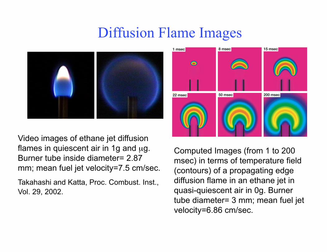
Diffusion Flame Images
Video images of ethane jet diffusion flames in quiescent air in 1g and µg. Burner tube inside diameter= 2.87 mm; mean fuel jet velocity=7.5 cm/sec.
Takahashi and Katta, Proc. Combust. Inst., Vol. 29, 2002.
Computed Images (from 1 to 200 msec) in terms of temperature field (contours) of a propagating edge diffusion flame in an ethane jet in quasi-quiescent air in 0g. Burner tube diameter= 3 mm; mean fuel jet velocity=6.86 cm/sec.
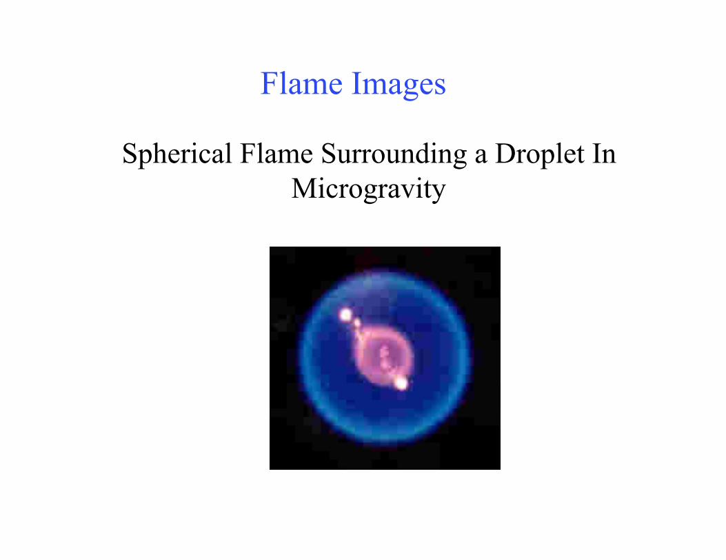
Flame Images
Spherical Flame Surrounding a Droplet In Microgravity
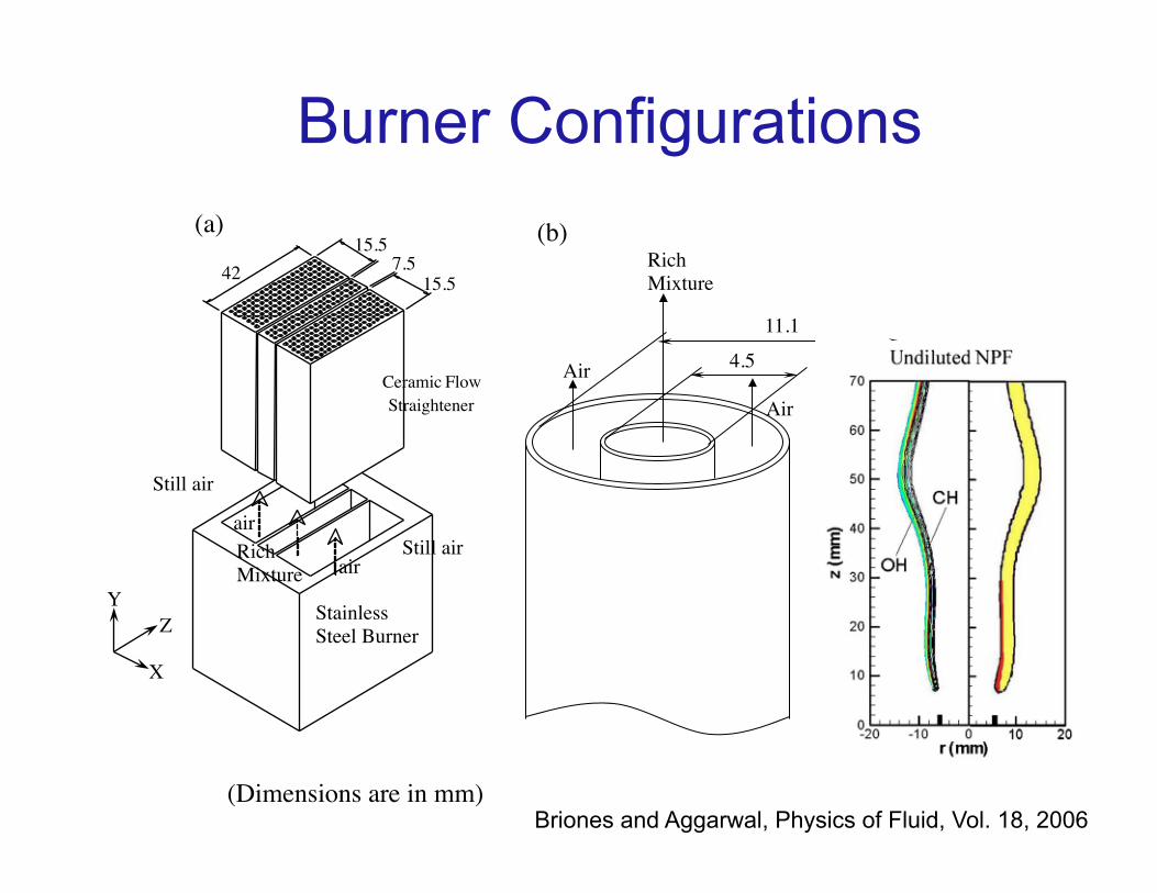
Burner Configurations
Still air
Ceramic Flow Straightener
Stainless Steel Burner
4215.5
15.57.5
air
air
Still air
X
ZY
RichMixture
(Dimensions are in mm)
4.5
11.1
Rich Mixture
Air
Air
(b)(a)
Briones and Aggarwal, Physics of Fluid, Vol. 18, 2006
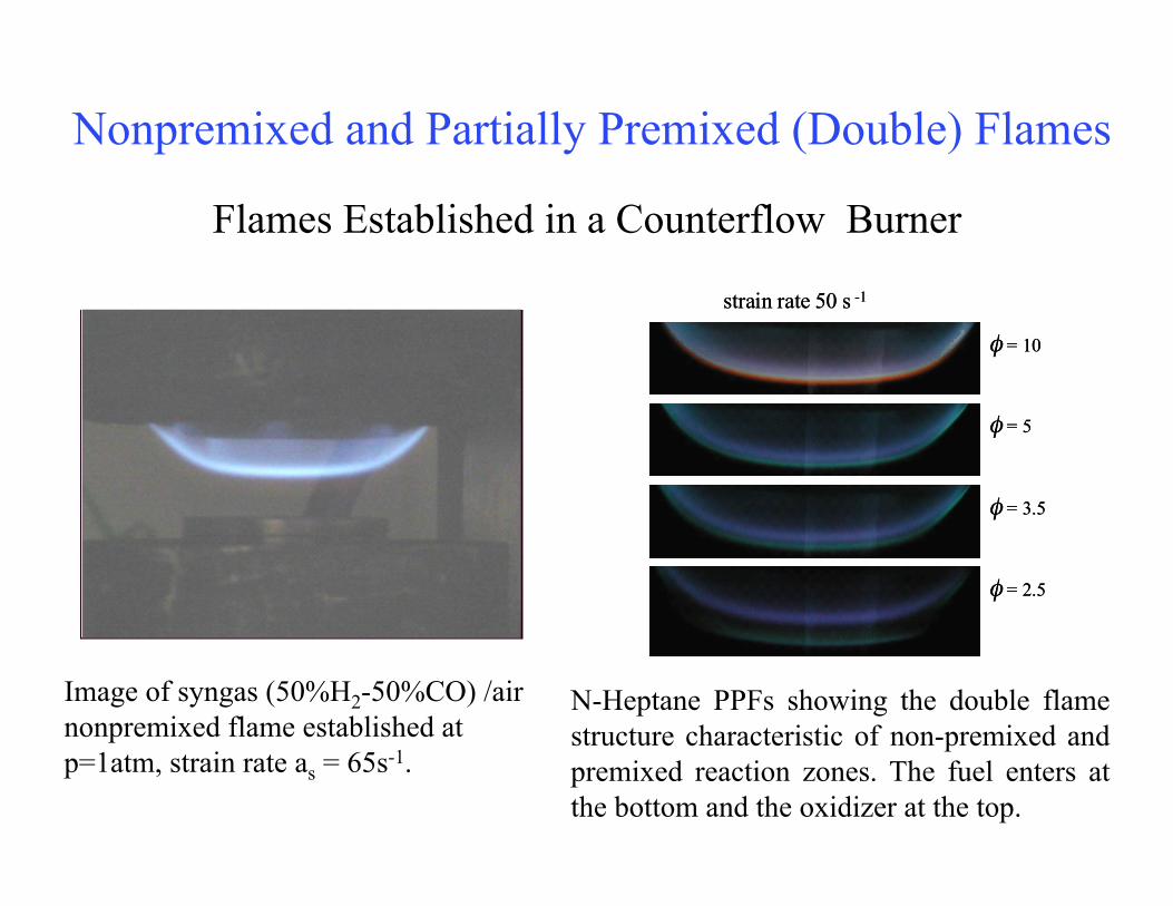
Nonpremixed and Partially Premixed (Double) Flames
Flames Established in a Counterflow Burner
Image of syngas (50%H2-50%CO) /air nonpremixed flame established at p=1atm, strain rate as = 65s-1.
strain rate 50 s -1
φ = 10
φ = 5
φ = 3.5
φ = 2.5
strain rate 50 s -1
φ = 10
φ = 5
φ = 3.5
φ = 2.5
N-Heptane PPFs showing the double flame structure characteristic of non-premixed and premixed reaction zones. The fuel enters at the bottom and the oxidizer at the top.
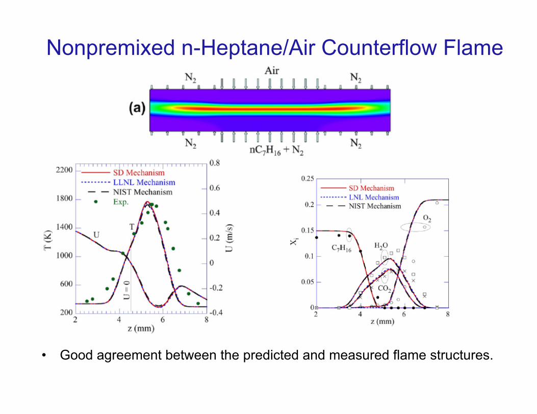
Nonpremixed n-Heptane/Air Counterflow Flame
• Good agreement between the predicted and measured flame structures.
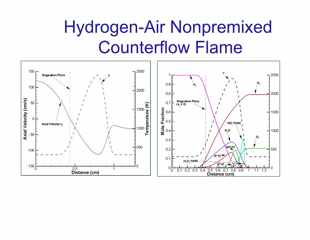
Hydrogen-Air Nonpremixed Counterflow Flame
Laminar Nonpremixed (Diffusion) Flames
• Introduction • Nonreacting Laminar Jet • Laminar Jet Flame • Flame Lengths for Circular (Axisymmetric) and Slot
burners • Counterflow flames • Partially Premixed Flames
References: Turns (Chapter 9), Kuo

Laminar Nonpremixed Flames
Introduction • Fuel and oxidizer are unmixed before they are transported to the reaction
zone (flame). • Nonpremixed flames are the most common in practical systems. Examples:
• Burning of liquid fuel droplets (gas turbine, diesel, and rocket engine combustors)
• Candle flame, match, cigarette lighter • Pool fires • Burning of solids and liquid-fueled combustors contain significant regions
of nonpremixed combustion • Most fires involve nonpremixed combustion
• Most residential gas appliances such as furnaces (gas heaters) and cooking ranges involve laminar nonpremixed or partially premixed flames.
• A laminar jet flame represents a fundamental flame, and has been extensively investigated.
Topics and Approaches
• Scale Analysis • Constant Density Solution: Equations 9.8-9.13 • Solution Based on Flame Sheet Approximation: Equations
9.23-9.29. • Solution Based on the Conserved Scalar Approach, Mixture
fraction (f): Equations 9.23, 9.24, 9.30-9.34 • Numerical Solution and State Relationships • Non-Dimensional Equations: Equations 9.36-9.40 • Laminar jet flame height: various solutions
§ Important Characteristics Flame height and shape Flame Structure Emissions
Turns: Chapter 9
Laminar Nonpremixed Flames
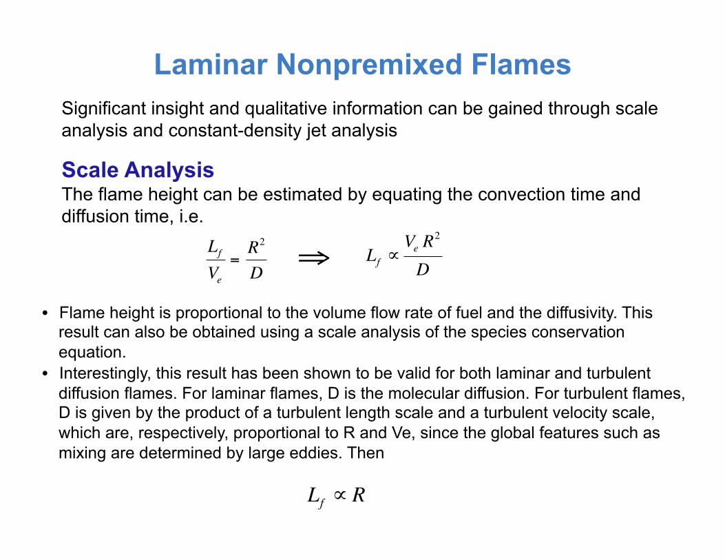
• Flame height is proportional to the volume flow rate of fuel and the diffusivity. This result can also be obtained using a scale analysis of the species conservation equation.
• Interestingly, this result has been shown to be valid for both laminar and turbulent diffusion flames. For laminar flames, D is the molecular diffusion. For turbulent flames, D is given by the product of a turbulent length scale and a turbulent velocity scale, which are, respectively, proportional to R and Ve, since the global features such as mixing are determined by large eddies. Then
Scale Analysis The flame height can be estimated by equating the convection time and diffusion time, i.e.
€
LfVe
=R2
D
€
Lf ∝Ve R
2
D⇒
€
Lf ∝ R
Significant insight and qualitative information can be gained through scale analysis and constant-density jet analysis
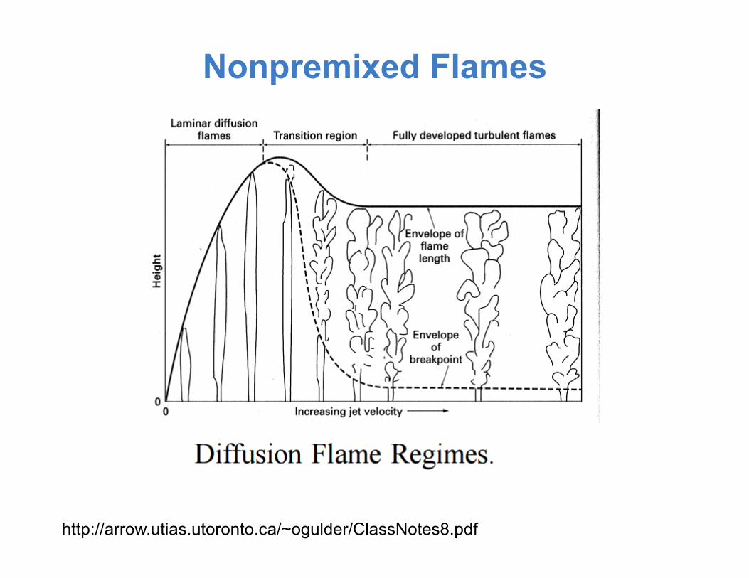
Nonpremixed Flames
http://arrow.utias.utoronto.ca/~ogulder/ClassNotes8.pdf
Laminar Nonpremixed Flames
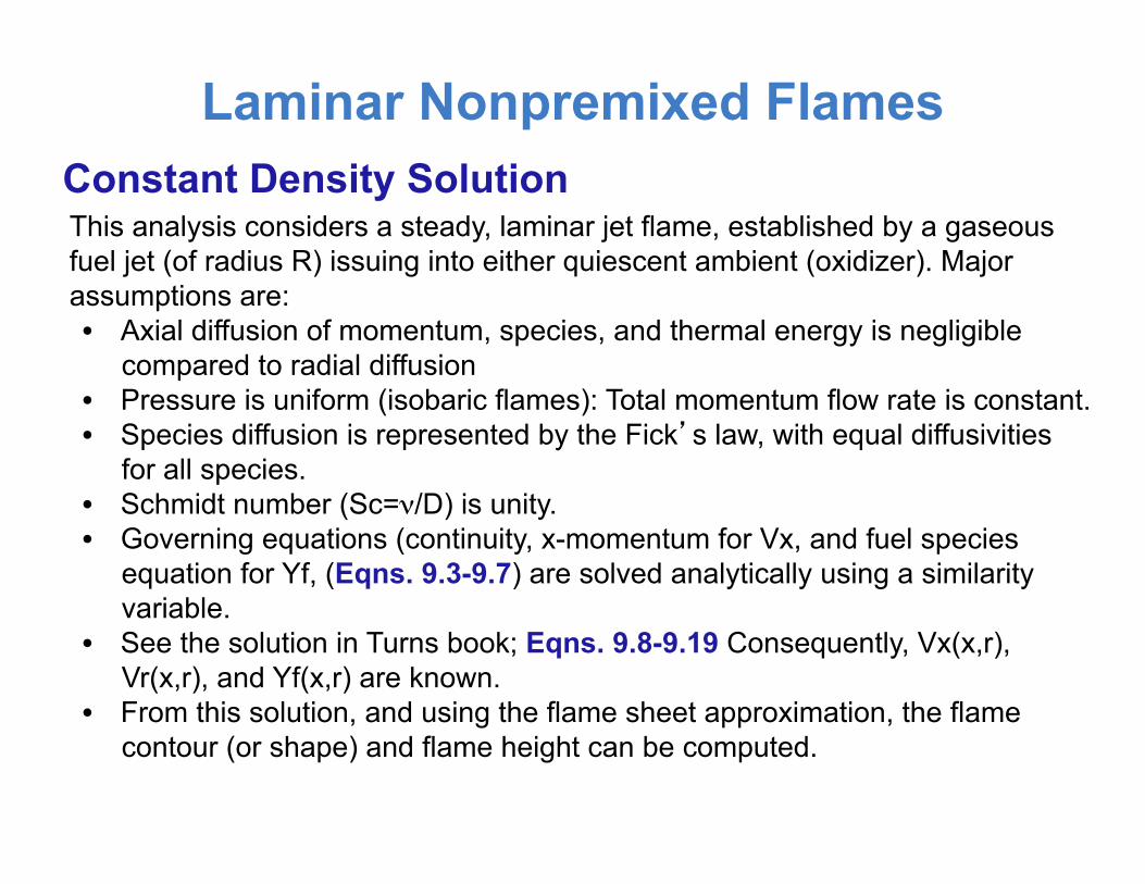
This analysis considers a steady, laminar jet flame, established by a gaseous fuel jet (of radius R) issuing into either quiescent ambient (oxidizer). Major assumptions are: • Axial diffusion of momentum, species, and thermal energy is negligible
compared to radial diffusion • Pressure is uniform (isobaric flames): Total momentum flow rate is constant. • Species diffusion is represented by the Fick’s law, with equal diffusivities
for all species. • Schmidt number (Sc=ν/D) is unity. • Governing equations (continuity, x-momentum for Vx, and fuel species
equation for Yf, (Eqns. 9.3-9.7) are solved analytically using a similarity variable.
• See the solution in Turns book; Eqns. 9.8-9.19 Consequently, Vx(x,r), Vr(x,r), and Yf(x,r) are known.
• From this solution, and using the flame sheet approximation, the flame contour (or shape) and flame height can be computed.
Constant Density Solution
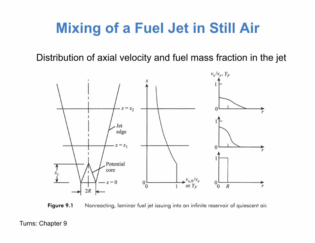
Mixing of a Fuel Jet in Still Air
Turns: Chapter 9
Distribution of axial velocity and fuel mass fraction in the jet
Laminar Nonpremixed Flames
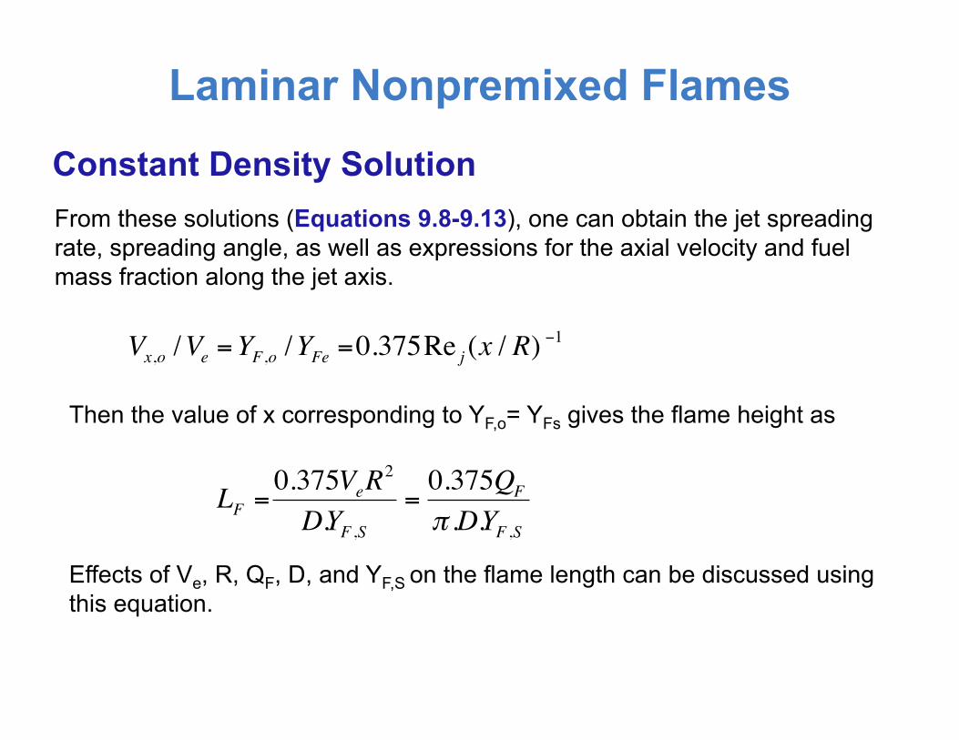
From these solutions (Equations 9.8-9.13), one can obtain the jet spreading rate, spreading angle, as well as expressions for the axial velocity and fuel mass fraction along the jet axis.
Constant Density Solution
Vx,o /Ve =YF,o /YFe =0.375Re j (x / R)−1
Then the value of x corresponding to YF,o= YFs gives the flame height as
€
LF =0.375VeR
2
D.YF ,S=0.375QF
π .D.YF ,SEffects of Ve, R, QF, D, and YF,S on the flame length can be discussed using this equation.

Laminar Nonpremixed Flames
This analysis considers a steady, laminar jet flame, established by a gaseous fuel jet (of radius R) issuing into either quiescent ambient (oxidizer) or a coflowing jet. Major assumptions are: • Axial diffusion of momentum, species, and thermal energy is negligible compared to
radial diffusion • Three species are considered: fuel, oxidizer, and product. Note, however, the
conserved scalar approach can be extended to many species. • Infinitely fast chemistry (large Damkohler limit) or flame-sheet approximation: The
flame is represented by a surface. Fuel and oxidizer are transported to the flame surface in stoichiometric proportions.
• Radiation heat transport is negligible. • Species diffusion is represented by the Fick’s law, with equal diffusivities for all
species. • Lewis number (Le=λ/(ρcpD)) is unity. • Pressure is uniform (isobaric flames).
Analysis Based on the Flame Sheet Approximation
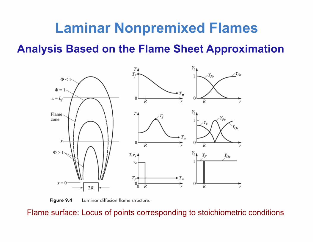
Laminar Nonpremixed Flames Analysis Based on the Flame Sheet Approximation
Flame surface: Locus of points corresponding to stoichiometric conditions
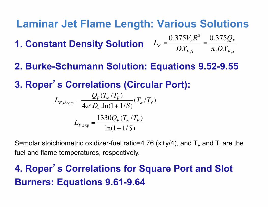
Laminar Jet Flame Length: Various Solutions
1. Constant Density Solution
€
LF =0.375VeR
2
D.YF ,S=0.375QF
π .D.YF ,S
2. Burke-Schumann Solution: Equations 9.52-9.55
3. Roper’s Correlations (Circular Port):
€
LF ,theory =QF (T∞ /TF )
4π .D∞.ln(1+1/S)(T∞ /Tf )
S=molar stoichiometric oxidizer-fuel ratio=4.76.(x+y/4), and TF and Tf are the fuel and flame temperatures, respectively.
€
LF ,exp =1330QF (T∞ /TF )ln(1+1/S)
4. Roper’s Correlations for Square Port and Slot Burners: Equations 9.61-9.64
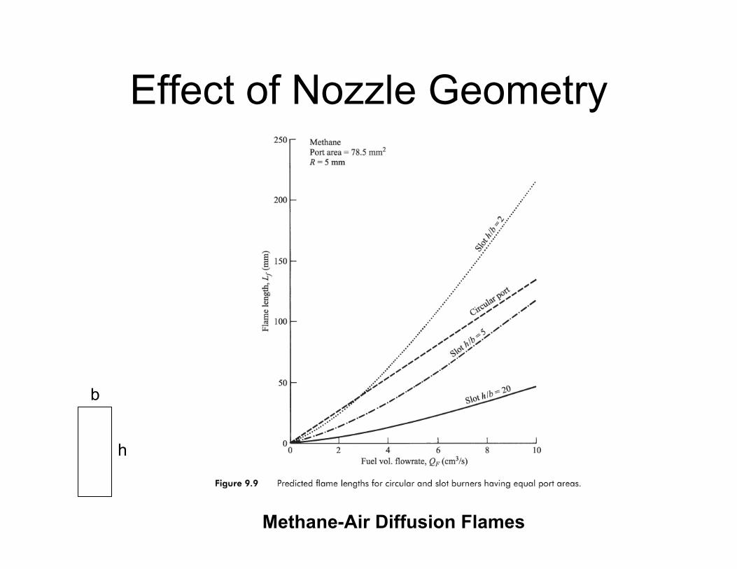
Effect of Nozzle Geometry
Methane-Air Diffusion Flames
h
b
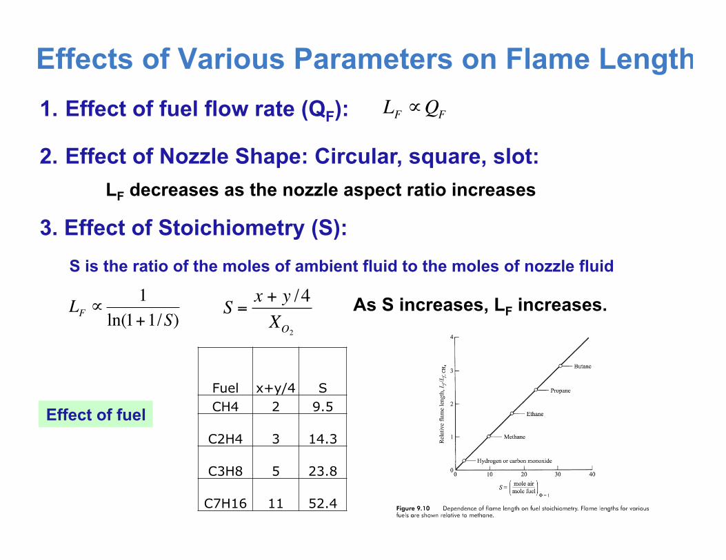
Effects of Various Parameters on Flame Length 1. Effect of fuel flow rate (QF):
2. Effect of Nozzle Shape: Circular, square, slot: LF decreases as the nozzle aspect ratio increases
3. Effect of Stoichiometry (S):
As S increases, LF increases.
€
S =x + y /4XO2
€
LF ∝1
ln(1+1/S)
€
LF ∝QF
S is the ratio of the moles of ambient fluid to the moles of nozzle fluid
Fuel x+y/4 S CH4 2 9.5
C2H4 3 14.3
C3H8 5 23.8
C7H16 11 52.4
Effect of fuel
Laminar Jet Flame Length: Effects of Various Parameters
€
Spure =x + y /4XO2
€
LF ∝1
ln(1+1/S)
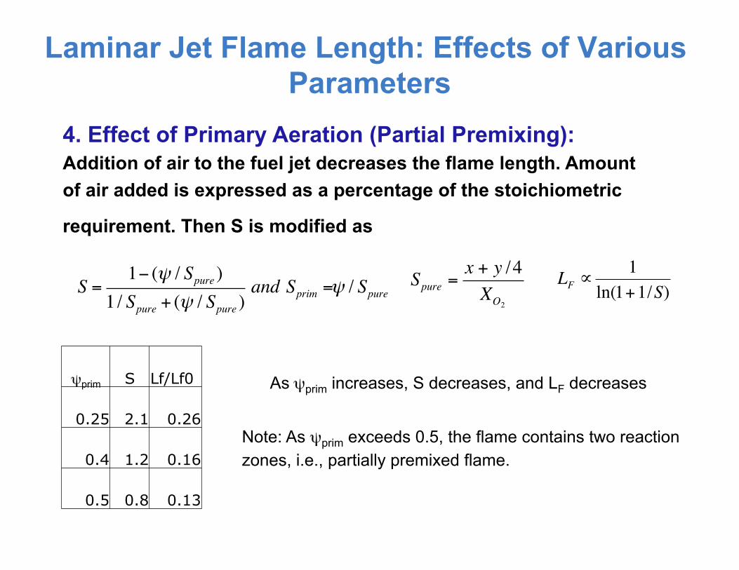
4. Effect of Primary Aeration (Partial Premixing): Addition of air to the fuel jet decreases the flame length. Amount of air added is expressed as a percentage of the stoichiometric
requirement. Then S is modified as
S =1− (ψ / Spure )
1 / Spure + (ψ / Spure )and Sprim =ψ / Spure
As ψprim increases, S decreases, and LF decreases ψprim S Lf/Lf0
0.25 2.1 0.26
0.4 1.2 0.16
0.5 0.8 0.13
Note: As ψprim exceeds 0.5, the flame contains two reaction zones, i.e., partially premixed flame.
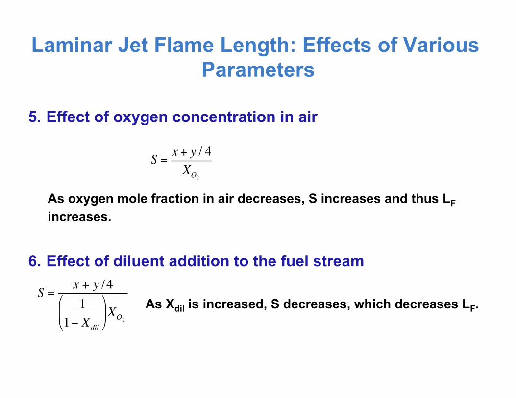
Laminar Jet Flame Length: Effects of Various Parameters
5. Effect of oxygen concentration in air
As oxygen mole fraction in air decreases, S increases and thus LF increases.
S = x + y / 4XO2
6. Effect of diluent addition to the fuel stream
€
S =x + y /41
1− Xdil
#
$ %
&
' ( XO2
As Xdil is increased, S decreases, which decreases LF.

Effect of Primary Aeration (Partial Premixing)
Effect of O2 Content in Air
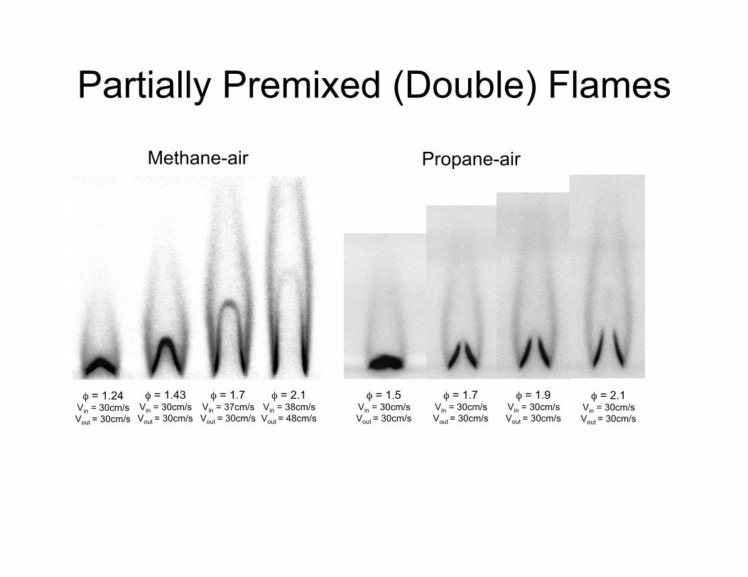
Partially Premixed (Double) Flames
Methane-air Propane-air
φ = 1.24 Vin = 30cm/s Vout = 30cm/s
φ = 1.43 Vin = 30cm/s Vout = 30cm/s
φ = 1.7 Vin = 37cm/s Vout = 30cm/s
φ = 2.1 Vin = 38cm/s Vout = 48cm/s
φ = 1.5 Vin = 30cm/s Vout = 30cm/s
φ = 1.7 Vin = 30cm/s Vout = 30cm/s
φ = 1.9 Vin = 30cm/s Vout = 30cm/s
φ = 2.1 Vin = 30cm/s Vout = 30cm/s
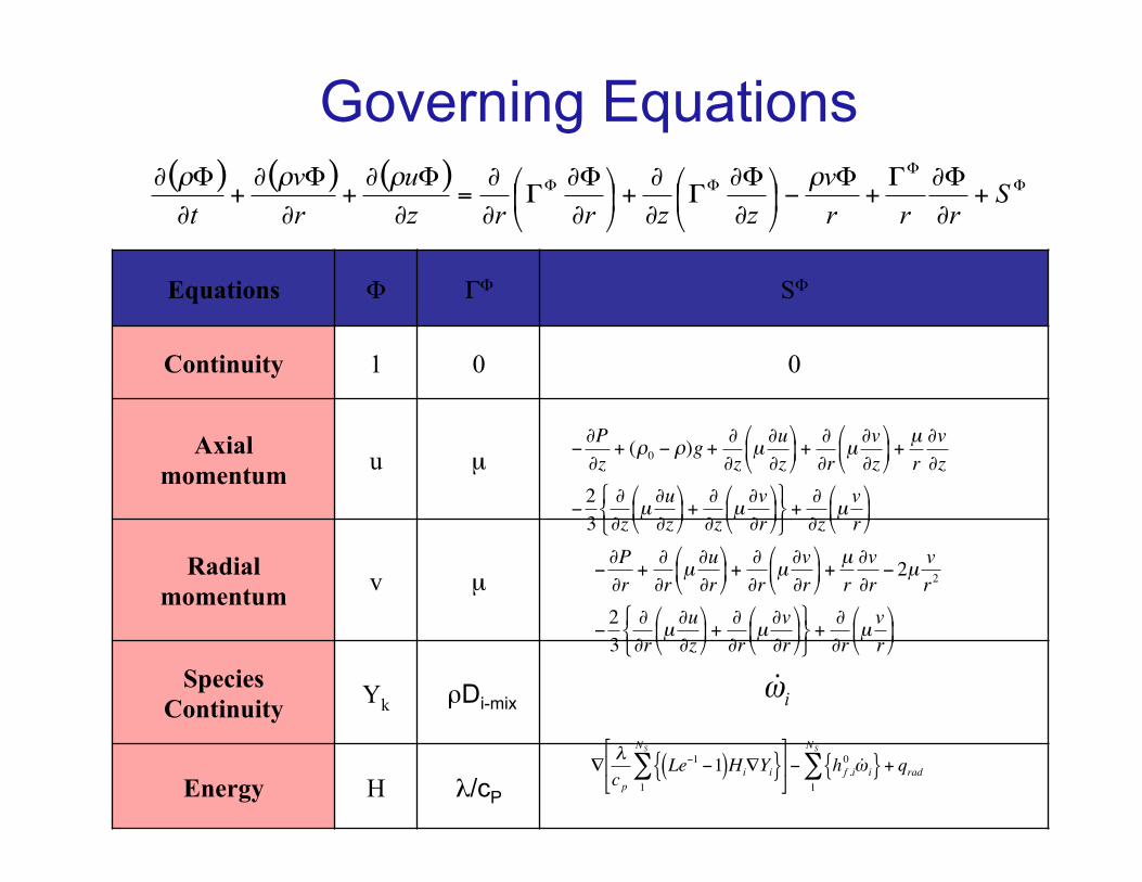
Equations Φ ΓΦ SΦ
Continuity 1 0 0
Axial momentum u µ
Radial momentum v µ
Species Continuity Yk ρDi-mix
Energy H λ/cP
Governing Equations ( ) ( ) ( ) Φ
ΦΦΦ +
∂
Φ∂Γ+
Φ−%&
'()
*∂
Φ∂Γ
∂
∂+%&
'()
*∂
Φ∂Γ
∂
∂=
∂
Φ∂+
∂
Φ∂+
∂
Φ∂ Srrr
vzzrrz
urv
tρρρρ
€
−∂P∂r
+∂∂r
µ∂u∂r
$
% &
'
( ) +
∂∂r
µ∂v∂r
$
% &
'
( ) +
µr∂v∂r− 2µ
vr2
−23
∂∂r
µ∂u∂z
$
% &
'
( ) +
∂∂r
µ∂v∂r
$
% &
'
( )
* + ,
- . /
+∂∂r
µvr
$
% &
'
( )
€
−∂P∂z
+ (ρ0 − ρ)g +∂∂z
µ∂u∂z
%
& '
(
) * +
∂∂r
µ∂v∂z
%
& '
(
) * +
µr∂v∂z
−23
∂∂z
µ∂u∂z
%
& '
(
) * +
∂∂z
µ∂v∂r
%
& '
(
) *
+ , -
. / 0
+∂∂z
µvr
%
& '
(
) *
iω
€
∇λcp
Le−1 −1( )Hi∇Yi{ }1
NS
∑&
' (
)
* + − h f ,i
0 ˙ ω i{ }1
NS
∑ + qrad
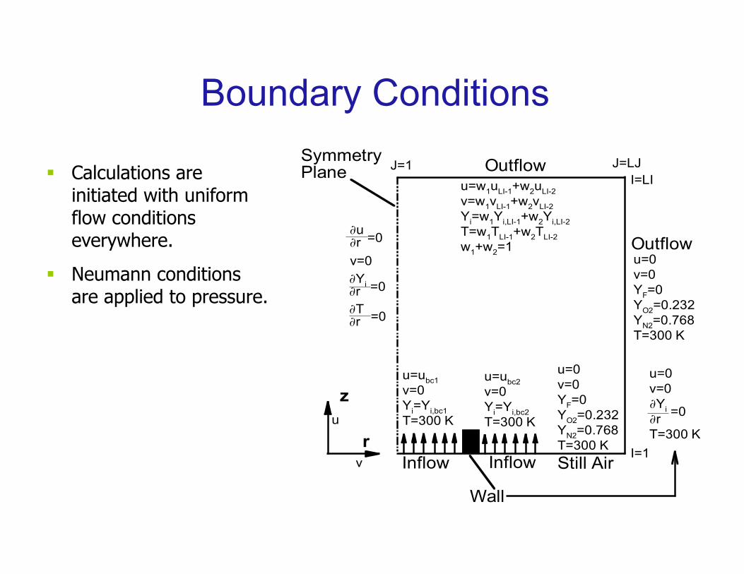
Boundary Conditions
r
z
∂T∂r =0
∂u∂r =0
∂Yi∂r
=0
v=0
SymmetryPlane
u=ubc2v=0Yi=Yi,bc2T=300 K
u=0v=0YF=0YO2=0.232YN2=0.768T=300 K
u=0v=0YF=0YO2=0.232YN2=0.768T=300 K
u=ubc1v=0Yi=Yi,bc1T=300 K
Outflow
Inflow Inflow
Wall
Outflowu=w1uLI-1+w2uLI-2v=w1vLI-1+w2vLI-2Yi=w1Yi,LI-1+w2Yi,LI-2T=w1TLI-1+w2TLI-2w1+w2=1
Still Air
u=0v=0∂Yi∂rT=300 K
=0
v
u
J=1
I=1
I=LIJ=LJ
§ Calculations are initiated with uniform flow conditions everywhere.
§ Neumann conditions are applied to pressure.
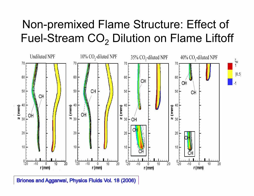
Non-premixed Flame Structure: Effect of Fuel-Stream CO2 Dilution on Flame Liftoff
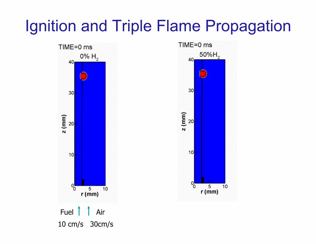
Ignition and Triple Flame Propagation
10 cm/s 30cm/s
Fuel Air