dibt ta - content.fischer.de · european technical assessment eta-17/0786 english translation...
TRANSCRIPT

DeutschesInstitut
für
Bautechnik DIBtApproval body for construction productsand types of construction
Bautechnisches Prüfamt
An Institution establlshed by the Federal andLaender Governments
European Technical
Assessment
★ ★Designated
according to "kArticle 29 of Regula
tion (EU) No 305/2011
and member of EOTA '
(European Organisation forTechnIcal
Assessment)
★ ★★
ETA-17/0786
of 13 December 2017
Member of
TAwww.eota.eu
English translation prepared by DIBt - Original Version in German language
General Part
Technical Assessment Body issuing theEuropean Technical Assessment:
Trade name of the construction product
Product familyto which the construction product belongs
Manufacturer
Manufacturing plant
•This European Technical AssessmentIcontains
This European Technical Assessment isJissued in accordance with Regulation (EU)IISIo 305/2011, on the basis of
Deutsches Institut für Bautechnik
j fischer injection system FIS PLUS! for use in masonry
i Injection system for use in masonry
fischerwerke GmbH & Co. KG
Klaus-Fischer-Straße 1
72178 Waldachtal
DEUTSCHLAND
fischerwerke
26 pages including 3 annexes which form an integral partof this assessment
ETAG029, April 2013,used as EAD according to Article 66 Paragraph 3 ofRegulation (EU) No 305/2011.
Deutsches Institut für Bautechnik
Kolonnenstraße 30 B110829 Berlin | GERMANY | Phone: +493078730-0 | Fax: +493078730-320 [Email; [email protected] lwww.dibt.de
Z2892.18 8.06.04-343/17

European Technical Assessment
ETA-17/0786
English translation prepared by DIBt
Deutsches
Institutfür
Bautechnik DIBt
Page 2 of 26 j 13 December 2017
The European Technical Assessment is issued by the Technical Assessment Body in its official language.Translations of this European Technical Assessment in other languages shall fully correspond to theoriginal issued document and shall be identified as such.
Communication of this European Technical Assessment, including transmission by electronic means,shall be in füll. However, partial reproduction may only be made with the written consent of the issuingTechnical Assessment Body. Any partial reproduction shall be identified as such.
This European Technical Assessment may be withdrawn by the issuing Technical Assessment Body, inparticular pursuant to Information by the Commission in accordance with Article 25(3) of Regulation(EU) No 305/2011.
Z2892.18 8.06.04-343/17

DeutschesInstitut
fürBautechnik DIßt
European Technical Assessment
ETA-17/0786
English translation prepared by DIBt
Page 3 of 26 113 December 2017
Specific Part
1 Technical description of the product
The fischer injectionsystem FIS PLUS for masonry is a bonded anchor (injection type)consisting of a mortar cartridge with fischer injection mortar FIS PLUS, FIS PLUS Low Speedand FIS PLUS High Speed, a perforated sieve sieeve and an anchor rod with hexagon nut andwasher or an internal threaded rod. The steel elements are made of zinc coated steel, stainlesssteel or high corrosion resistant steel.
The anchor rod is placed into a drilied hole filied with injection mortar and is anchored via thebond between steel element, injection mortar and masonry and mechanical interlock.
The product description is given in Annex A.
2 Specification of the intended use in accordance with the applicable EuropeanAssessment Document
The Performances given in Section 3 are only valid if the anchor is used in compliance with thespecifications and conditions given in Annex B.
The verifications and assessment methods on which this European Technical Assessment isbased lead to the assumption of a working life of the anchor of at least 50 years. The indicationsgiven on the working life cannot be interpreted as a guarantee given by the producer, but are tobe regarded only as a means for choosing the right products in relation to the expectedeconomically reasonable working life of the works.
3
3.1
3.2
3.3
Z2892.18
Performance of the product and references to the methods used for its assessment
Mechanical resistance and stability (BWR 1)
Essential characteristic Performance
Characteristic resistance for tension and shear loads See Annex C 1 - C 4
Characteristic resistance for bending moments See Annex C 5
Displacements under shear and tension loads See Annex C 5
Reduction Factorfor job Site tests (ß-Factor) See Annex C 6
Edge distances and spacing See Annex C7-C8
Safety in case of fire (BWR 2)
Essential characteristic Performance
Reaction to fire Anchorages satisfy requirements forClass AI
Resistance to fire No Performance assessed
Hygiene, health and the environment (BWR 3)
Regarding dangerous substances there may be requirements (e.g. transposed Europeanlegislation and national laws, regulations and administrative provisions) applicable to theproducts falling within the scope of this European Technical Assessment. In order to meet theprovisions of Regulation (EU) No 305/2011, these requirements need also to be complied with,when and where they apply.
8.06.04-343/17

European Technical Assessment
ETA-17/0786
English translation prepared by DIBt
Deutsches
Institutfür
Bautechnik DIBt
Page 4 of 26 113 December 2017
3.4 Safety in use (BWR 4)
The essential characteristics regarding Safety in use are included under the Basic WorksRequirement IVIechanical resistance and stability.
4 Assessment and verification of constancy of Performance (AVCP) system applied, withreference to its legal base
In accordance with guideline for European technical approval ETAG 029, April 2013 used asEuropean Assessment Document (EAD) according to Article 66 Paragraph 3 of Regulation (EU)No 305/2011 the appllcable European legal act is: [97/177/EC].
The system to be applied is: 1
5 Technical details necessary for the implementation of the AVCP system, as provided forin the applicable European Assessment Document
Technical details necessary for the implementation of the AVCP system are laid down in thecontrol plan deposited at Deutsches Institut für Bautechnik.
Issued in Berlin on 13 December 2017 by Deutsches Institut für Bautechnik
BD Dipl.-Ing. Andreas Kummerow
Head of Department
Z2892.18
beglaubigt:
Baderschneider
8.06.04-343/17

Page 5 of European Technical AssessmentETA-17/0786 of 13 December 2017
English translation prepared by DIBt
Deutsches
Institut
fürBautechnik DIßt
Installation conditlons part 1;
Threaded rods with perforated sieeve FIS H K; Installation in perforated and solid brick masonry
I t _
Pre-positioned Installation
FIS H 12x85 K
j FIS H 16x85 KFIS H 16x130 K
FIS H 20x85 K
FIS H 20x130 K
FIS H 20x200 K
^ttarn
Internat threaded anchors FIS E with perforated sieeve FIS H K; Installation In perforated and solidbrick masonry
3 instmax
Pre-positioned Installation
FIS H 16x85 K - FIS E 11 x85 M6 and M8
FIS H 20x85 K- FIS E 15x85 MIO and M12
he,=ho =tflx =
h =
effective anchorage depthdepth of drill holethickness of fixture
thickness of masonry
do= nominal drill bit diameterdf= diameter of ciearance hole in the fixture
Tinstmax = maximum torque moment
fischer Injectionsystem FIS PLUS for masonry
Product descriptionInstallation condition, part 1: in perforated and solid brick masonry
Z3855.18
Annex A1
8.06.04-343/17
Page 6 of European Technical AssessmentETA-17/0786 of 13 December 2017
English translation prepared by DIBt
DeutschesInstitut
fürBautechnik DIBt
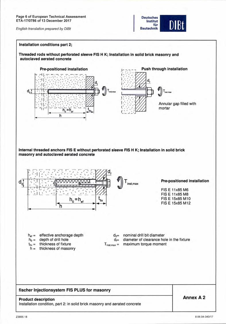
Installation conditlons part 2;
Threaded rods without perforated sieeve FIS H K; Installation In solid brIck masonry andautociaved aerated concrete
Pre-positioned Installation
'fj I-^'<7 •: 7,"^> 'IK' - - I
d.
iä, "aT-;'
7i-
' v' . N/ I / N
' '/n '
Push through Installation
d.
Annular gap filied withmortar
Internal threaded anchors FIS E without perforated sieeve FIS H K; Installation in solid brickmasonry and autociaved aerated concrete
T -^~L 7" .r
T\r
4 ^^1 U v
s . X- -'v ^
ho=hef
hef = effective anchorage depthho = depth of drill holetfix = thickness of fixtureh = thickness of masonry
l/z
—•
insf.maxPre-positioned Installation
FIS E 11x85 IVI6
FIS E 11x85 M8
FIS E 15x85 MIOFIS E 15x85 MI2
do= nominal drill bit diameterd(= diameter of ciearance hole in the fixture
Tinst,max = maximum torque moment
fischer Injectionsystem FIS PLUS for masonry
Product descriptionInstallation condition, part 2: in solid brick masonry and aerated concrete
Z3855.18
Annex A 2
8.06.04-343/17

Page 7 of European Technical AssessmentETA-17/0786 of 13 December 2017
English translation prepared by DIBt
Deutsches
Institut
für
Bautechnik DIBt
1o
«
to
M8, MIO, Ml 2
alternative pointgeometry
FIS H 12x85 K
FIS H 16x85 K
FIS H 20x85 K
1. Mortar cartridge
2. Threaded rod
3. Washer
Shuttle cartridge(sizes: 345 ml; 360 ml; 390 ml; 950 ml; llOOml; 1500 ml)
Imprint: FIS PLUS, FIS PLUS High Speed, FIS PLUSLowSpeed, processing notes, shelf-life, pistontravel scale, curingtimesand processing times(depending on temperature),
Coaxlal cartridge(sizes: 100 ml; 150 ml; 300 ml;380 ml; 400ml; 410 ml)
Imprint: FIS PLUS, FIS PLUSHigh Speed , FISPLUSLow Speed, processing noles, shelf-life,piston Iravelscale, curinglimes and processingtimes (depen-ding on temperature), hazard codes,sizes, volume.
FISEM6, FIS E 11x85 M8FIS E MIO, FIS E 15x85 MI2
alternative headgeometry
©
FIS H 20x200 K
4. Hexagon nut
5. Internal threaded anchor FIS E
6. Perforated sieeve FIS H K
fischer Injectionsystem FIS PLUS for masonry
Product descriptlonCartridges, anchor rods, internal threaded anchors, perforated sieeves
Annex A 3
Z3855.18 8.06.04-343/17

Page 8 of European Technical AssessmentETA-17/0786 of 13 December 2017
English translation prepared by DIBt
TableAl: Materials
DeutschesInstitut
fürBautechnik DIBt
Part Designation Material
1 Mortar cartridge mortar, hardener; filier
Steel, zinc plated Stainless steel A4High corrosion-resistant steel C
2
Threaded rod Property class5.8 or 8.8;
EN ISO 898-1:2013
zinc plated ä 5 um,EN ISO 4042:1999 A2K
or hot-dip galvanizeds 40 |jm
EN ISO 10684:2004
fuk^ 1000 N/mm^As > 8 %
fracture elongation
Property class50, 70 or 80
EN ISO 3506-1:2009
1.4401; 1.4404;1.4578; 1.4571;1.4439; 1.4362;1.4062, 1.4662,
1.4462
EN 10088-1:2014
fukS 1000 N/mm^As > 8 %
fracture elongation
Property class50 or 80
EN ISO 3506-1:2009
or property class 70with fyk= 560 N/mm^
1.4565; 1.4529EN 10088-1:2014
fuk^ 1000 N/mm^As > 8 %
fracture elongation
3
Washer
ISO 7089:2000
zinc plated ä 5 pim,EN ISO 4042:1999 A2K
or hot-dip galvanizedä 40 um
EN ISO 10684:2004
1.4401; 1.4404;1.4578;1.4571;1.4439; 1.4362
EN 10088-1:2014
1.4565;1.4529EN 10088-1:2014
4
Hexagon nut Property class5or8:
EN ISO 898-2:2012
zinc plated s 5 um,ISO 4042:1999 A2K
or hot-dip galvanizeda: 40 um
EN ISO 10684:2004
Property class50, 70 or 80
EN ISO 3506-1:2009
1.4401; 1.4404;1.4578; 1.4571;1.4439; 1.4362
EN 10088-1:2014
Property class50, 70 or 80
EN ISO 3506-1:2009
1.4565; 1.4529EN 10088-1:2014
5
Internal threaded anchor
FISE
Property class5.8
EN 10277-1:2008-06
zinc plated 2 5 um,ISO 4042:1999 A2K
Property class70
EN ISO 3506-1:2009
1.4401; 1.4404;1.4578; 1.4571;1.4439; 1.4362
EN 10088-1:2014
Property class70
EN ISO 3506-1:2009
1.4565; 1.4529EN 10088-1:2014
Screw or threaded rod for
internal threaded anchor
FISE
Property class5.8 or 8.8;
EN ISO 898-1:2013
zinc plated 2 5 um,ISO 4042:1999 A2K
Property class70
EN ISO 3506-1:20091.4401; 1.4404;1.4578; 1.4571;1.4439; 1.4362
EN 10088-1:2014
Property class70
EN ISO 3506-1:2009
1.4565; 1.4529EN 10088-1:2014
6Perforated sieeve
FIS H KPP/PE
fischer Injectionsystem FIS PLUS for masonry
Product descriptionMaterials
Z3855.18
Annex A 4
8.06.04-343/17

Page 9 of European Technical AssessmentETA-17/0786 of 13 December 2017
English translation prepared by DIBt
Deutsches
Institut
fürBautechnik
Anchorages subject to:
• Stalle and quasi-statlc loads
Specifications of intended use part 1
DIßt
Base materlals:
• Solid brIck masonry (Use category b) and autociaved aerated concrete (Use category d), acc. to Annex B8.
Note; The characteristic resistance Is also valld for larger brIck sIzes and higher compressive strength of the
masonry unit.
• Hollow brick masonry (use category c), according to Annex B8
• Mortar strength class of the masonry M2,5 at minimum according to EN 998-2:2010
• For other bricks In solid masonry, hollow or perforated masonry and autociaved aerated concrete, the
characteristic resistance of the anchor may be determined by job Site tests according to ETAG 029, Annex B
under consideratlon of the ß-factor according to Annex C6, Table C4
Temperature Range:
• From - 40''C to +80''C (max. Short term temperature +80°C and max. long term temperature +50°C)
Use conditlons (Environmental conditlons):
• Dry and wet structure (regarding injection mortar)
• Structures subject to dry internal conditions exlst
(zinc coated steel, stainless steel or high corrosion reslstant steel)
• Structures subject to external atmospheric exposure including Industrial and marine environment or exposure
to permanently damp internal condition, If no particular aggressive conditions exlst
(stainless steel or high corrosion reslstant steel)
• Structures subject to external atmospheric exposure and to permanently damp internal condition, If other
particular aggressive conditions exlst (high corrosion resistant steel)
Note: Particular aggressive conditions are e.g. permanent, alternating Immersion in seawater or the splash
Zone of seawater, Chloride atmosphere of Indoor swimming pools or atmosphere with extreme chemical
Pollution (e.g. In desulphurizatlon plants or road tunnels where de-icing materlals are used)
fischer Injectionsystem FIS PLUS for masonry
Intended Use
Specifications part 1
Z3855.18
Annex B1
8.06.04-343/17

Page 10 of European Technical AssessmentETA-17/0786 of 13 December 2017
English translation prepared by DIBt
Deutsches
Institut
für
Bautechnik
Specifications of intended use part 2
Design:
DIBt
The anchorages have to be designed in accordance with the ETAG 029, Annex C, Design method A under the
responsibility of an engineer experienced in anchorages and masonry work
Applies to all bricks, if no other values are specified:
NrK = NRk,8 = NRk,p = NR|<,b = NRk,pb
Vrk = Vri<,8= VRK.b = Vrk,c = VRk,pb
• Verifiable caiculation notes and drawings have to be prepared taking account the relevant masonry in the
region of the anchorage, the loads to be transmitted and their transmission to the supports of the structure. The
Position of the anchor is indicated on the design drawings
Installation:
• Category d/d: -Installation and use in dry structures
• Category w/w: -Installation and use in dry and wet structures
• Hole drilling by hammer drill mode
• In case of aborted hole: The hole shall be filied with mortar
• Bridging of unbeahng layer (e.g. plaster) see Annex B 4 (Table B1.3)
• Anchor installation carried out by appropriately qualified personnel and under the supervision of the person
responsible for technical matters of the Site
• Fastening screws or threaded rods (including nut and washer) must comply with the appropriate material and
property class of the fischer internal threaded anchor FIS E
• minimum curing time see Annex B5. Table B3
• Commercial Standard threaded rods, washers and hexagon nuts may also be used if the following
requirements are fulfilied:
Material dimensions and mechanical properties of the metal parts according to the specifications are given in
Annex A4, Table AI
Conformation of material and mechanical properties of the metal parts by inspection certificate 3.1 according to
EN 10204:2004, the documents shall be stored
Marking of the threaded rod with the envisage embedment depth. This may be done by the manufacturer of the
rod or by a person on job site
fischer Injectionsystem FIS PLUS for masonry
Intended Use
Specifications part 2
Z3855.18
Annex B 2
8.06.04-343/17

Page 11 of European Technical AssessmentETA-17/0786 of 13 December 2017
English translation prepared by DIBt
DeutschesInstitut
für
Bautechnik
h- Width across flat
SWMarking
m • » /•
...
DIßt
Marking- possible marking setting depthProperty class (p.c.) 8.8, Stainless steel A4, p.c. 80 or high corrosion-resistant steel C, property class 80: •Stainless steel A4, property class 50 and high corrosion-resistant steel C, property class 50: ••
Table B1.1: Installation Parameters for threaded rod without perforated sieeveSize M8 M10 M12
Nominal drill hole diameter
Q.
II
CLo
[mml 10 12 14
Width across flat SW [mml 13 17 19
Effective anchorage depth'' het.mln [mml 50
Depth of drill hole ho = hef hsf.tnax [mm] h-30 and s 200 mm
Effective anchorage depth AAC haf.mln mml 100
hef.max [mml 120
Maximum torque moment [Nml 10
Max. torque moment for autociaved aerated concrete [Nml 1 2
Diameter of clearance Pre-position anchorage d,s [mm] 9 12 14
hole inthe fixture push through anchorage dfS [mm] 11 14 16
hef.min ^ hefS hef.max iS pOSSible.
fischer Internai threaded anchor FIS E
FIS E 11x85 M6, FIS E 11x85 M8
^
FIS E 15x85 MIO, FIS E 15x85 M12
L„20
\
Marking: size, e.g. M8stainless steel A4: e.g. M8 A4high corrosion-resistant steel C: e.g. M8 C
Table B1.2: Installation parameters for internai threaded anchor FIS E withoutperforated sieeve
201
LE.min
< ^
M
i
Size FIS E M6 M8 MIO M12
diameter of internai threaded anchor dn [mm] 11 15
Nominal drill hole diameter dnom=do [mm] 14 18
Depth of drill hole ho [mm] 85
Effective anchorage depth LH=het [mm] 85
Maximum torque moment Tinst max [Nm] 4 10
Max. torque moment for ^ ,autociaved aerated concrete ^ ^ 1 2
Diameter of clearance hole in the . . , ,fixture
7 9 12 14
Screw-in depth LE.min [mm] 6 8 10 12
fischer Injectionsystem FIS PLUS for masonry
Intended Use
Installation parameters, part 1
Z3856.18
Annex B 3
8.06.04-343/17

Page 12 of European Technical AssessmentETA-17/0786 of 13 December 2017
English translation prepared by DIBt
Deutsches
Institut
fürBautechnik DIBt
Perforated sieeves FIS H 12x85; 16x85; 16x130; 20x85; 20x130; 20x200 K
L sieeve ,
Marking:size ^ ^ "^rkingDsieeve X Lsieevee.g. 16x85
Table B1.3: Installation paranfieters (threaded rod and internal threaded anchor withperforated sieeve; only pre-positioned anchorage)
Size FIS H...K 12x85 16x85 16x130" 20x85 20x130" 20x200"
Nominal drill hole
dlameter (do = Dsieevs) dnom=do [mm] 12 16 20
Depth of drill hole ho [mm] 90 90 135 90 135 205
Effective anchorage hef.mln [mm] 85 85 110 85 110 180
depth'' het.max [mm] 85 85 130 85 130 200
Size of threaded rod [-] M8 M8,, MIO M12
Size of internal threaded
anchor [-] —
FISE
11x85
f^6/M8
....
FISE
15x85
MI O/Ml 2
.... ....
Maximum torquemoment threaded rod
and internal threaded
anchor
Tinst.max [mm] 2
hef.mln ^ hefS hef.max iS pOSSlblG.Bridging of unbearing layer (e.g. plaster) possible
fischer Injectionsystem FIS PLUS for masonry
Intended Use
Installation parameters, part 2.
Z3855.18
Annex B 4
8.06.04-343/17

Page 13 of European Technical AssessmentETA-17/0786 of 13 December 2017
English translation prepared by DIBt
Cleaning brush BS (Steel brush)
DeutschesInstitut
fürBautechnik DIBt
Only for solid bricks and aerated concrete
Table B2: Parameters of steel brushThe size of tfie steel brush refers to the nominal drill bit diameter
Drill hole
diameterdo [mm] 10 12 14 16 18 20
Brush
diameterdb.nom [mm] 11 14 16 20 20 25
Table 83: Maximum processing time of the mortar and minimum curing time(Düring the curing time of the mortar the masonry temperature may not fall below the listed minimumtemperature).
Minimum curing time teurefminutesl
Temperature atanchoring base
rc]
FISPLUS
HighSpeed
FIS
PLUS
FIS PLUSLow
Speed
-10 to -5 12 hours
>-5 to ±0 3 hours 24 hours
>±0 to +5 90 3 hours 6 hours
>+5 to +10 45 90 3 hours
>+10 to +20 30 60 2 hours
>+20 to +30 45 60
>+30 to +40 35 30
'' Forwet bricks the curing time mustbe doubiedMinimum cartridge temperature +5°CMinimum cartridge temperature ±0°C
fischer Injectionsystem FIS PLUS for masonry
Intended Use
Steel brush
Processing times and curing times
Z3855.18
System-temperature
(mortar)[°C]
Maximum processing time t^xkfminutesl
FIS
PLUSHigh
Speed
FIS
PLUS
FISPLUSLow
Speed
±0 5
+5 5 13 20
+10 3 9 20
+20 1 5 10
+30 4 6
+40 2 4
Annex B 5
8.06.04-343/17

Page 14 of European Technical AssessmentETA-17/0786 of 13 December 2017
English translation prepared by DIBt
Installation instructions part 1
Deutsches
Institut
für
Bautechnik DIBt
Installation and Preparing the cartridge In solid brIck and autociaved aerated concrete(without perforated sieeve)
t [B
< ' '4'
Drill the hole. Depth of drill holeho and drill hole diameter do see
Table B1.1 orBI.2
Remove the sealing cap
Place the cartridge into asuitable dispenser.
Fill approximately 2/3 ofthe drill hole with mortar
Always begin from thebottom of the hole to
eliminate voids''.
y ^
Blow out the drill hole
two times by hand.Brush the drill hole two
times using an adequatesteel brush (see TableB2) and blow out twotimes again
Screw on the static
mixer (the spiral in thestatic mixer must be
clearly visible)
Press out approximately10 cm of material until
the mortar is permanent-ly grey in colour. Mortarwhich is not grey incolour will not eure and
must be disposed off.
For push throughInstallation (not FIS E) fillthe annular gap also withmortar.
Only use clean and oil-free anchor elements. Mark the threaded rod forsetting depth. Press the threaded rod or internal threaded anchor FIS E downto the bottom of the hole, turning it slightly by hand while doing. After insertingthe anchor element, excess mortar must emerge around the anchor element.
Wait for the specified curingtime teure see Table B3
For the exact quantity of mortar see manufacturer's specification.
fischer Injectionsystem FIS PLUS for masonry
Intended Use
Installation instructions part 1 in solid brick and aerated concrete
Z3855.18
Mounting the fixtureTinst.maxSee Table B1.1 or B1.2
Annex B 6
8.06.04-343/17

Page 15 of European Technical AssessmentETA-17/0786 of 13 December 2017
English translation prepared by DIBt
DeutschesInstitut
für
Bautechnik DIBt
Installation instructions part 2
Installation In perforated or solid brIck wIth perforated sieeve (pre-positioned anchorage)
Drill the liole. Deptli of drillInole lio and drill hole diameterdo seeTable B1.3
When install perforated sieeves in solidbricl<s or solid areas of hollow bricks, alsoclean the hole by blowing out andbrushing
ft B•Remove the sealingcap
Place the cartridgeinto a suitable
dispenser
Insert the
perforated sieeveflush with the
surface of the
masonry or plaster.
Wait for the specified curing timeteure See Table B3
Screw on the stalle mixer
(the Spiral in the staticmixer must be clearlyvisible)Press out approximately 10cm of material until the
mortar is permanent-ly greyin colour. IVIortar which is
not grey in colour will noteure and must be disposedoff
Fill the perforated sieevecompletely with mortarbeginning from the bottomof the hole".
Only use clean and oil-free anchor elements. IVlarkthe threaded rod for setting depth. Insert thethreaded rod or the internal threaded anchor FIS Eby hand using light turning motions until reaching thesetting depth marking (threaded rod) or flush with thesurface (internal threaded anchor).
ly^ounting the fixture.Tin8t.maxSee Table B1.3
" For theexact quantity ofmortar see manufacturer's specification.
fischer Injectionsystem FIS PLUS for masonry
Intended Use
Installation instructions part 2 in hollow brick masonry
Z3855.18
Annex B 7
8.06.04-343/17

Page 16 of European Technical AssessmentETA-17/0786 of 13 December 2017
English translation prepared by DIBt
Deutsches
Institutfür
Bautechnik
Table B 4: Summary of bricks and blocks
Brick No. 1
Solid brick Mz
according toEN 771-2
pa 1,8 [kg/dm®]fb s 10 or 20
[N/mm^]
Brick No. 2
Solid sand-lime
brick according toEN 771-2
p 2 1,8[kg/dm^fb^lOor 20
[N/mm^]
Brick No. 3
Solid sand-lime
brick according toEN 771-2
pa 1,8 [kg/dm^fbä10or20
[N/mm®]
Brick No. 4
Sand-lime hollow
brick according toEN 771-2
p2 l,4[kg/dm^fbai2or 20
[N/mm®]
Brick No. 5
Perforated brick
HLz according toEN 771-1
p i 0,9[kg/dm^fb 2 10[N/mm®]
Imaging of the bricks are not scaied
o. a
L-Il
fischer Injectionsystem FIS PLUS for masonry
Intended Use
Types and dimensions of blocks and bricks
Z3855.18
Brick No. 6
Perforated brick
HLz according toEN 771-1
p 2 1,4 [kg/dm®]fb ä 20 [N/mm^]
Brick No. 7
Perforated brick
HLz according toEN 771-1
p S: 1,0 [kg/dm^fb ä 10[N/mm^]
Brick No. 8Perforated brickHLz filied withmineral woolaccording toEN 771-1
p ä 0,6[kg/dm^fb ä 8 [N/mm^lBrlck-No. 9
Light-weight con-crete hollow block
Hbl according toEN 771-1
p 2 1,0[kg/dm^fbä 4 [N/mm®]
Brick No. 10
Autociaved
aerated concrete
blockp 2 0,35, 0,5 or0,65 [kg/dm®]fbS2, 4or6[N/mm®]
T .r
DIBt
• •
-JT-
Annex B 8
8.06.04-343/17

Page 17 of European Technical AssessmentETA-17/0786 of 13 December 2017
English translation prepared by DIBt
Deutsches
Institut
für
Bautechnik DIBt
Table B5.1: Allocation of threaded rods^\ perforated sleeves^^ '̂ and perforated orsolid bricks
Kind of masonry Brick Valid anchor rods and perforated sieeves
Brick No. 1
Solid bricl< Mz
according toEN 771-2
p 2 1,8[l<g/dm^fbä lOor 20
[N/mm^]
BrIck No. 2
Solid sand-lime
brick according toEN 771-2pa 1,8 [kg/dm^fbälOor 20
[N/mm^]
Brick No. 3
Solid sand-limebrick according toEN 771-2
p a 1,8 [kg/dm®]fb ä 10 or 20
[N/mm^]
Brick No. 4
Sand-lime hollow
brick according toEN 771-2
pä1,4 [kg/dm^fbä12or 20
[N/mm^]
Brick No. 5
Perforated brick
HLz according toEN 771-1
p 0,9[kg/dm®]fb s 10[N/mtn^]
Brick No. 6
Perforated brick
HLz according toEN 771-1
pai,4 [kg/dm^fbs 20 [N/mm^]
M8;M10:M12
FISE 11x85
M6, MB
M8;M10:M12
FISE 11x85
M6, M8
FISH 12x85 K
FISH 16x85 K
FIS H 20x85 K
FISH 16x130 K
FIS H 20x130 K
FISH 12x85 K
FISH 16x85 K
FIS H 20x85 K
FISH 16x130 K
FISH 20x130 K
FISH 12x85 K
FISH 16x85 K
FIS H 20x85 KFISH 16x130 K
FISH 20x130 K
FISH 12x85 KFISH 16x85 K
FIS H 20x85 K
Otlier combinations can be used after job Site tests acc. to ETAG 029, Annex B.SIeeve/anchor rod combination see table 81.3
The ß- factor for this job Site tests are given in Table C4
Imaging of tiie bricks are not scaied
fischer Injectionsystem FIS PLUS for masonry
Intended Use
Allocation of threaded rods, perforated sieeves and bricks, part 1
Annex B 9
Z3855.18 8.06.04-343/17

Page 18 of European Technical AssessmentETA-17/0786 of 13 December 2017
English translation prepared by DIBt
DeutschesInstitut
für
Bautechnik DIBt
Table B5.2: Allocation of threaded rods^\ perforated sleeves '̂̂ ^ and perforated or solidbricks
Kind of masonry
Brick No. 7
Perforated brick
HLz according toEN 771-1
p 2 1,0[kg/dm®]fb a 10[N/mm^]
Brick No. 8Perforated brickHLz filied withmineral woolaccording toEN 771-1
p 2 0,6 [kg/dm®]fbä 8 [N/mm^]Brick-No. 9
Light-weight con-crete hollow block
Hbl according toEN 771-1
p ä 1,0[kg/dm^fb 2 4 [N/mm®]
Brick No. 10
Autociaved
aerated concrete
blockp 2 0,35, 0,5 or0,65 [kg/dm^]fb 2 2, 4 or 6Mmmf]
Brick Valld anchor rods and perforated sieeves
FISH 12x85 K
FISH 16x85 K
FIS H 20x85 K
FISH 20x130 K
FISH 12x85 K
FISH 16x85 K
FIS H 20x85 K
FISH 16x130 K
FISH 20x130 K
FIS H 20x200 K
FIS Hl 2x85 K
FISH 16x85 K
FIS H 20x85 KFISH 16x130 K
FISH 20x130 K
M8;M10;M12
FIS El 1x85 M6
FIS El 1x85 M8
FIS E 15x85 MIO
FIS E 15x85 MI2
Other combinations can be used after job site tests acc. to ETAG 029, Annex B.SIeeve/anchor rod combination see table 81.3
The ß- factor for this job Site tests are given in Table C4
Imaging of the bricks are not scaied
fischer Injectionsystem FIS PLUS for masonry
Intended Use
Allocation of threaded rods, perforated sIeeves and bricks, part 2
Annex B10
Z3855.18 8.06.04-343/17

Page 19 of European Technical AssessmentETA-17/0786 of 13 December 2017
English translation prepared by DIBt
Deutsches
Institutfür
Bautechnik DIBt
Table C1.1: Characteristic vaiues of resistance under tension ioads and undersliear loads
Density p[kg/dmT Anchor size or screw
size in internal
threaded anchor
Effective
anchorageCharacteristic resistance
[kN]
BrickPerforated
sieeve
FISH...K
depth Nrk Vrk
Compressivestrength fb[N/mm^]
hei,min[mm]
hef.max[mm]
Temp.50/80°C All categories
d/d 1w/w
MS 50 200 4,0 2,5 2,5
M10 50 79 3,5 2,04,0
MIO 80 199 5,0 3,0
O00
MIO 200 200 8,5 7,5 8.5
M12 50 79 3,0 2,04.0
M12 80 199 5,5 3,5
M12 200 200 8,0 5,0 8.5
withoutFIS E 11x85 M6/M8 85 85 5,5 3,5 2.5
M8 50 200 5,5 3,5 4.0
No.l
Solid brick Mz
M10 50 79 5,0 3,06,0
MIO 80 199 7,0 4,5
P^1,8 MIO 200 200 8,5 8,5 8,5fb2:20 M12 50 79 4,5 3,0
5,5M12 80 199 8,0 5,0
M12 200 200 8,5 7,0 8,5
FIS E 11x85 M6/M8 85 85 8,0 5,0 4,0
M8 50 200
MIO 50 79 2,5 1.54,0
MIO 80 199
p2 1,8 MIO 200 200 8,5 6,0fb2 10
M12 50 792,5 1.5
M12 80 199 5,0
M12 200 200 8,5 6,5
without FIS E 11x85 M6/M8 85 85 2,5 1,5 3,0
M8 50 200
No.2
Solid sand-limebrick
MIO 50 79 3.5 2,05,5
MIO 80 199
p^ 1,8fb^20
M10 200 200 8,5 8,5
M12 50 793,5 2,0
M12 80 199 7,0
M12 200 200 8,5 8,5
FIS E 11x85 M6/M8 85 85 3,5 2,0 4,0
Imaging of the bricks are not scaied
fischer Injectionsystem FIS PLUS for masonry
Performances
Characteristic values of resistance under tension loads and under shear loads, part 1
Z3855.18
Annex C1
8.06.04-343/17

Page 20 of European Technical AssessmentETA-17/0786 of 13 December 2017
English translation prepared by DIBt
DeutschesInstitut
fürBautechnik DIBt
Table C1.2: Characteristic values of resistance under tension ioads and undersliear ioads
Brick
Density p[kg/dm']
Compressivestrength fb[N/mm^]
Perforated
sieeveFISH...K
Anchor size or
screw size in
internal threaded
anchor
Effective
anchoragedepth
Characteristic resistance[kN]
Nrk Vrk
bet.min[mm]
het.max[mm]
Temp.50/80''C All categories
d/d w/w
No.3
Solid sand-limebrick
1,8fb2 10
12x85 M8 85 85 6,0 3,53,0
16x85 FISE 11x85 M6 85 85 3,5 2,0
16x85M8/M10,
FISE 11x85 M885 85 3,5 2,0
3,520x85
MI 2,FISE 15x85
MI O/Ml 285 85 8,5 6,5
16x130 M8/M10 110 130 3,5 2,0
20x130 MI 2 110 130 7,0 4,5
psi,8fbS20
12x85 M8 85 85 8,5 5,04,5
16x85 FIS El 1x85 M6 85 85 5,5 3,0
16x85M8/M10,
FISE 11x85 M885 85 5,5 3,0
5,520x85
MI 2,FISE 15x85
MI O/Ml 285 85 8,5 8,5
16x130 M8/M10 110 130 5,0 3,0
20x130 M12 110 130 8,5 6,0
No.4
Sand-lime hollowbrick
pai,4fbä12
12x85 M8 85 85 2,5 2,52,5
16x85 FIS El 1x85 M6 85 85 3,0 2,5
16x85M8/M10,
FIS El 1x85 M885 85 3,0 2,5 4,5
20x85
MI 2,FISE 15x85
MI O/Ml 285 85
3,5 3,0 4,516x130 M8/M10 110 130
20x130 M12 110 130
p2 1,4fba20
12x85 M8 85 85 4,5 4,0 4,5
16x85 FIS El 1x85 M6 85 85 5,0 4,0 4,0
16x85M8/M10,
FISE 11x85 M885 85 5,0 4,5 7,5
20x85
MI 2,FISE 15x85
MI O/Ml 2
85 85
6,0 5,5 7.516x130 M8/M10 110 130
20x130 MI 2 110 130
Imaglng of the bricks are not scaied
fischer Injectionsystem FIS PLUS for masonry
Performances
Characteristic values of resistance under tension loads and under shear loads, part 2
Z3855.18
Annex C 2
8.06.04-343/17
Page 21 of European Technical AssessmentETA-17/0786 of 13 December 2017
English translation prepared by DIBt
DeutschesInstitut
fürBautechnik DIßt
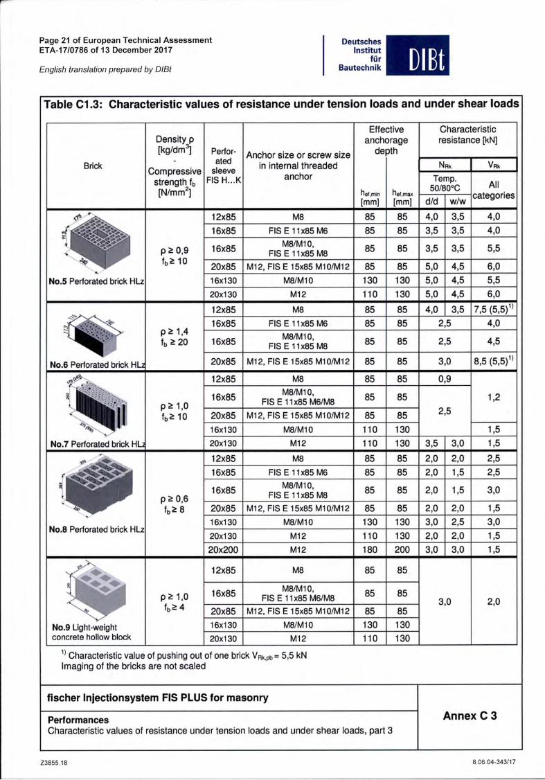
Table C1.3: Characteristic values of resistance under tension loads and under shear loads
Blick
Density p[kg/dmT
Compressivestrength fb[N/mm^]
Perfor
ated
sieeve
FISH...K
Anchor size or screw size
in internal threaded
anchor
Effei
anch(
de
hei,min[mm]
ctive
Drage
pth
hel.max[mm]
Characteristic
resistance [kN]
Nrk Vrk
Temp.50/80''C All
categoriesd/d w/w
<
No.5 Perforated brick HLz
pä0,9fbS 10
12x85 M8 85 85 4,0 3,5 4.0
16x85 FIS E 11x85 M6 85 85 3,5 3,5 4.0
16x85M8/M10,
FIS E 11x85 M885 85 3,5 3.5 5.5
20x85 M12, FIS E 15x85 M10/M12 85 85 5,0 4,5 6.0
16x130 M8/M10 130 130 5,0 4,5 5.5
20x130 M12 110 130 5,0 4,5 6.0
pai.4fba20
12x85 K/18 85 85 4,0 3,5 7.5 (5.5)"16x85 FIS E 11x85 M6 85 85 2,5 4.0
16x85M8/M10,
FIS E 11x85 M885 85 2,5 4.5
No.6 Perforated brick HL2 20x85 MI 2, FIS E 15x85 MI O/Ml 2 85 85 3,0 8.5 (5.5)"
N0.7 Perforated brick HL
IVIV00
12x85 M8 85 85 0,9
1,216x85M8/M10,
FIS E 11x85 M6/M885 85
2,520x85 MI 2, FIS E 15x85 MI O/Ml 2 85 85
16x130 M8/M10 110 130 1,5
20x130 M12 110 130 3,5 3,0 1,5
*>
N0.8 Perforated brick HLz
pä0,6fbS8
12x85 M8 85 85 2,0 2,0 2,5
16x85 FIS E 11x85 M6 85 85 2,0 1,5 2,5
16x85M8/M10,
FIS E 11x85 M885 85 2,0 1,5 3.0
20x85 M12, FIS E 15x85 M1O/Ml 2 85 85 2,0 2.0 1,5
16x130 M8/M10 130 130 3,0 2.5 3.0
20x130 M12 110 130 2,0 2.0 1,5
20x200 M12 180 200 3,0 3,0 1,5
1
pS1.0fbä4
12x85 M8 85 85
3,0 2.016x85
M8/M10,FIS E 11x85 M6/M8
85 85
N0.9 Light-weightconcrete hollow block
20x85 MI 2, FISE15x85M10/M12 85 85
16x130 M8/M10 130 130
20x130 M12 110 130
Characteristic value of pushing out of one brick VRK,pb= 5,5 kNImaging of the bricks are not scaied
fischer Injectionsystem FIS PLUS for masonry
Performances
Characteristic values of resistance under tension loads and under shear loads, part 3
Z3855.18
Annex C 3
8.06.04-343/17

Page 22 of European Technical AssessmentETA-17/0786 of 13 December 2017
English translation prepared by DIBt
DeutschesInstitut
fürBautechnik DIBt
Table C1.4: Characteristic values of resistance under tension loads and undershear loads
Brick
Density p[kg/dm^i
Compressivestrength fb[N/mm^]
Perforated
sieeve
FISH..,K
Anchor size or
screw size in
infernal threaded
anchor
Effei
anch(
de
flet,min[mm]
ctive
3rage
pth
hef.ttiax[mm]
Characteristic resistance[kN]
Nrk Vrk
Temp.SO/SCC
Allcategories
d/d w/w
No.lO Aerated concreteolock
p ä 0,35without
M8 100 120
1.5
1.2
M10 100 120 1.2
M12 100 120 1.5
FIS E 11x85
[^6/M8
FIS E 15x85
M10/M12
85 1.2
päO.5fb2 4
without
m 100 120 2.0 2,5
MIO 100 120 2,5 2,0
M12 100 120 2,5
FIS E 11x85M6/M8
FIS E 15x85
M10/M12
85 2.0 2,0
p ä 0,65fb^B
without
M8 100 120 3,5 3,0 3,0
MIO 100 1205,0 4,5
3,0
M12 100 120 3,5
FIS E 11x85
M6/M8
FIS E 15x85
MI O/Ml 2
85 3,5 2,5
Imaging of the bricks are not scaied
fischet Injectionsystem FIS PLUS for masonry
Performances
Characteristic values of resistance under tension loads and under shear loads, part 4
Z3855.18
Annex C 4
8.06.04-343/17

Page 23 of European Technical AssessmentETA-17/0786 of 13 December 2017
English translation prepared by DIBt
DeutschesInstitut
fürBautechnik DIBt
Table C2: Characteristic bending momentsSIze MS M10 M12
Zinc-plated steel Property class5.8 [Nm] 19 37 65
O) 8.8 [Nm] 30 60 105c
f-
Stainless steel A45
Property class50 [Nm] 19 37 65
E 70 [Nm] 26 52 92
.9C
80[Nm] 30 60 105
o
2 gn) ^
High corrosion-resistantsteel C
50 [Nm] 19 37 65
Property class 70 '̂ [Nm] 26 52 92
s: Oü E 80 [Nm] 30 60 105
"fuk= 700 N/mm^: fyk=560 N/mm^
Table C2.1: Characteristic bending moments for internal threaded anchors FIS E
Size FIS E MB MB M10 M12
^ zinc Property 5.8 [Nm] 8 19 37 65
c plated class of•g » steel, screw 8.8 [Nm]^ oc
12 30 60 105
" ^ stainless PfopertySa4 ''0[Nm]
0) 2 sieeiM4 screw11 26 52 92
cä o high^ corrosion TnrMmi
S resistantSteel C
11 26 52 92
Tabelle C3: Displacements under tension loads and shear loads
MaterialN
[kN]5No
[mm]5Noo
[mm]V
[KN]8Vo
[mm]5Voo
[mm]
solid units and
autociaved aerated
concrete
Nrk0,03 0,06
Vrk0,59 0,88
1,4 *Ym 1.4 *Ym
hollow
units
Nrk0,03 0,06
Vrk1.71 2,56
1.4 *Ym 1,4 *YM
fischer Injectionsystem FIS PLUS for masonry
Performances
Characteristic bending moments; displacements
Annex C 5
Z3855.18 8.06.04-343/17

Page 24 of European Technical AssessmentETA-17/0786 of 13 December 2017
English translation prepared by DIBt
DeutschesInstitut
fürBautechnik DIBt
Table C4: ß- factor for job site tests according to ETAG 029, Annex B
Using categories w/w d/d
Temperature ränge ["C] 50/80 50/80
Brick Size^'
M8 0,57
iVIIO 0,59
Solid brick0,96
M12
FIS E 11x85
M6/M8
FIS E 15x85M10/M12
0,60
Hollow brick All sizes 0,86 0,96
Autociaved aerated
concreteAll size 0,73 0,81
fischer Injectionsystem FIS PLUS for masonry
Performances
ß- factors for job site tests
Z3855.18
Annex C 6
8.06.04-343/17

Page 25 of European Technical AssessmentETA-17/0786 of 13 December 2017
English translation prepared by DIBt
DeutschesInstitut
fürBautechnik DIBt
Table C5: Edge distance and spacing (instailation with and witliout sieeves)
Direction 0 bed joint II Group factor Min. thickness
of the masonrymembers
Brick No. hef[mm]
Ccr —Ctnin Smin Scr SmIn Scr 1 1[mm] [mm] [mm] [mm] [mm] Og.N ög.V Og.N Og.V [mm]
1
50 100 75 60'' 150 2 2 1,5 1,4
hef + 30(ä 80)
80 100 75 60^' 240 2 2 1,5 1.4
200 150 75 240 2
2
50 100 75 240 2
80 100 75 240 2
200 150 75 240 2
385 100 115 240 2
130 100 115 240 2
4 all sizes 100 115 100 240 2 2 1,5 1,5
5 all sizes 100 115 240 2
6 all sizes 100 11 5 240 2
7 all sizes 100 100 240 100375
(500)='' 1 1 1 1
8 all sizes 120 2^15 250 2
9 all sizes 80 240 365 2
10 all sizes 100 250 300 2
only valid for tension loads, for shear loads Sminll = Scrspacing for alternative brick dimension, see table B4, brick 7
fischer Injectionsystem FiS PLUS for masonry
Performances
Edge distance and spacing
Z3855.18
Annex C 7
8.06.04-343/17

Page 26 of European Technical AssessmentETA-17/0786 of 13 December 2017
English translation prepared by DIBt
DeutschesInstitut
für
Bautechnik
c*«""aJ
10
:L . . J
0
'O -0
eo
(0
* Only, if joints are visible and/or vertical joints are not filied with mortar
Smin II
Smln"*"ScrIl
Sor-*-Ccr = Cmln
ag,N IIttg.V II
Og.V-^
= Minimum spacing parallel to bed joint
= Minimum spacing vertical to bed joint
= Characteristic spacing parallel to bed joint
= Characteristic spacing vertical to bed joint
= Edge distance
= Group factor for tension ioad parallel to bed Joint= Group factor for shear Ioad parallel to bed joint
= Group factor for tension ioad vertical to bed joint
= Group factor for siiear ioad vertical to bed joint
0
For s > Sct ocg = 2For Smin^ s s Scr Og according to table C5N®nk= ag.N'Npk: V%= ag.v'VpKN®Rk = ttg.N II • Clg.N-^ • Nrk: V°Rk =Ctg,V II • CCg V"'- • Vpk
(Group of 2 anchors)(Group of 4 anchors)
fischer Injectionsystem FIS PLUS for masonry
Performance
Definition of minimum edge distance, minimum spacing and group factors
Z3855.18
DIßt
'*g.N
V-^
co
%hI
«B.V II
Annex C 8
8.06.04-343/17