dial and electronic indicators and gagesjwdonchin.com/starrett/catalog/pdf/139.pdf · special...
TRANSCRIPT
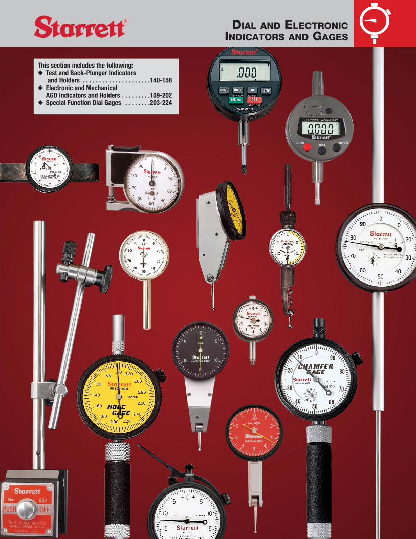
This section includes the following:◆ Test and Back-Plunger Indicators
and Holders . . . . . . . . . . . . . . . . . . . . .140-158◆ Electronic and Mechanical
AGD Indicators and Holders . . . . . . . . .159-202◆ Special Function Dial Gages . . . . . . . .203-224
DIAL AND ELECTRONICINDICATORS AND GAGES

J.W. DONCHIN CO. 4841-43 W. Chicago Ave. • Chicago, IL 60651-3224Ph: 773-261-2182 • Fax: 773-261-2867 • [email protected] • www.jwdonchin,com
Test Indicators and Holders
140 TEST INDICATORS AND HOLDERS Introduction
141 Dial Test Indicators with dovetail mounts Series Nos. 708, 708M,709, 709M
142 Attachments for Starrett Nos. 708, 709, and 811 Series Test Indicators - Series No. 708
Collet Adaptor for use with any 3/16" diameter Indicator Attachment
Collet Adaptor with Swivel Post
143 Dial Test Indicators with swivel head Series No. 811, 811M
144 Dial Test Indicators with swivel head Series No. 811, 811M
145 Dial Test Indicators with swivel head Series No. 811, 811M
146 Last Word® Dial Test Indicators Series No. 711, 711M
147 Attachments for Starrett No. 711 Series Last Word® Dial Test Indicators Series No. 711
148 Attachments for Starrett No. 711 Series Last Word® Dial Test Indicators Series No. 711
149 Attachments for Starrett No. 711 Series Last Word® Dial Test Indicators Series No. 711
150 Back-Plunger Dial Indicators - Series Nos. 650, 650M, 651, 651M
Attachments for Starrett No. 650 and No. 651 Series Back-Plunger Dial Test Indicators
151 Back-Plunger Dial Indicators Series No. 641, 641M
152 Universal Back-Plunger Dial Indicators Series No. 196, 196M
153 Attachments for Starrett Nos. 196, 196M Series Universal Indicators Series No. 196
154 Magnetic Base Indicator Holder Series No. 657AA
154 Magnetic Base Indicator Holder with swivel post assembly Series No. 657A
155 No. 657 Series Sets
156 Flex-O-Post Indicator Holders with magnetic base Series No. 657T
157 Magnetic Base Universal Indicator Holderwith triple-jointed arm and fine-adjustment Series No. 657-1, 657-2
158 Magnetic Base with triple-jointed arm Series No. 660

Test Indicators and HoldersTest indicators are primarily used for the testing or checking ofparts and for machine setups, but they are also frequently usedfor general production purposes, either singly or “ganged” inmultiples. They are an indispensable part of a toolmaker’s kit oftools.
Test indicators come in two types – the plunger style and the lever style. The lever style is more adaptable to smaller, confinedworking areas, but both types are amazingly versatile.
The lever style differs in measuring because the lever contactmoves in an arc rather than in a straight line, as in the plungerstyle. This can cause a slight inaccuracy called a “cosine error”if reasonable care is not used in setting the angle of the lever to the workpiece. If, for example, a lever was set off 20º more at the start of a reading than it should have been, there could be anerror of .0006� in a .010� range (0.012 mm in a 0.2mm range).This is not important when zeroing-out, but only when looking for a measurement.
There are other test indicators on the market that have pear-shaped contacts to try to compensate for this error. We do not think this is effective. We think it is best to keep your contactat or near 90º to the direction of movement unless themanufacturer specifies another angle. (See Illustration.) Testindicators should always be “loaded” 1/10 to 1/4 of a turn beforemeasuring.
Test indicators are not hand-held absolute measuring tools. Theyare comparative instruments that check and compare to knownstandards or that are used to zero-out setups. We have a broadselection of holders shown in this section that allows you to usethese indicators to the fullest. We’ve never seen a job that one of these holders combined with one of our test indicators could not handle.
140
TEST INDICATORSAND HOLDERS
Incorrect Correct

141
Dial Test Indicators withdovetail mountsNo. 708 Series .020�
No. 708M Series 0.2mm
No. 709 Series .060�
No. 709M Series 0.8mm
These precision test indicators weredesigned to be positioned for easy andaccurate readability. The versatility of theangled head, combined with the threedovetail mounts eliminates the need forhaving both vertical and horizontal styletest indicators. These are the features thatmake this series of test indicators superiorto ordinary types:
Readability Features◆ Angled head for better reading position◆ Large 1-3/8� (35mm) dial diameter◆ Revolution count hand on Nos. 708B and
709B models for easy reading
Accuracy Features◆ Precision gear-driven design with
smooth, jeweled movement◆ Meet or exceed ISO accuracy
specification◆ For extreme accuracy we recommend
positioning the lever contact so that it isapproximately 15º from being horizontalwith the workpiece
Specifications on next page.
Versatility Features◆ Three dovetail positioning mounts work
with existing test indicator accessories◆ Inch reading indicators are available
with easy-to-read, shaded white, solidred, or solid black dials – millimeterreading indicators with solid yellow dials
◆ Contact point reverses automatically,always maintaining clockwise handrotation
◆ Narrow body for inreach ability◆ Satin chrome finish for durability◆ Models with twice the range of ordinary
types◆ Long carbide contacts 13/16� (20mm)
are furnished as standard on mostindicators. Exceptions are the contactsfor the Nos. 709ALZ and 709ALCZ whichare 1-23/64� (34mm) long; and Nos.709MALZ and 709MALCZ which are 1-5/64� (28mm)
◆ Contact points with other ball diametersalso available individually, as listed
◆ Contacts are frictionally adjustable andreplaceable
Left-to-right: Nos. 708BZ, R708AZ, B709AZ.
Angled head for easy reading.
TEST INDICATORSAND HOLDERS

142
Inch ReadingCarbide Contact Point With Standard Letter
Grad- Dial Length Ball Dia. Dial of Certification**
uation Range Reading In. (mm) In. (mm) Description Color Catalog No. EDP No. Catalog No. EDP No.
White 708AZ 64212 708AZ W/SLC 66866
Without Attachments Red R708AZ 64603 R708AZ W/SLC 66867
.010�Black B708AZ 64607 B708AZ W/SLC 66868
.0001� 0-5-0 13/16� .078� White 708ACZ 64217 708ACZ W/SLC 66869(20mm) (2mm) With Attachments* Red R708ACZ 64604 R708ACZ W/SLC 66870
Black B708ACZ 64608 B708ACZ W/SLC 66871
.020�Without Attachments
White708BZ 64213 708BZ W/SLC 66874
With Attachments* 708BCZ 64218 708BCZ W/SLC 66875
White 709AZ 64214
Without Attachments Red R709AZ 64605
13/16�Black B709AZ 64609
.030� 0-15-0 (20mm) White 709ACZ 64219
.078� With Attachments* Red R709ACZ 64606
.0005� (2mm) Black B709ACZ 64610
.050� 0-25-0 1-23/64� Without Attachments 709ALZ 65857(34.4mm) With Attachments*
White709ALCZ 65858
.060� 0-15-0 13/16� Without Attachments 709BZ 6421520mm) With Attachments* 709BCZ 64220
Millimeter Reading
0.002mm 0.2mm 0-100-0 5/8� .078� Without AttachmentsYellow
708MAZ 65864 708MAZ W/SLC 66872(16mm) (2mm) With Attachments* 708MACZ 65865 708MACZ W/SLC 66873
0.8mm 0-40-0 13/16� Without Attachments 709MAZ 64216
0.01mm(20mm) .078� With Attachments*
Yellow709MACZ 64221
1.0mm 0-50-0 1-5/64� (2mm) Without Attachments 709MALZ 67092(28.4mm) With Attachments* 709MALCZ 67093
Individual Carbide Contact Points‡
Length Ball Diameter
Fits Series Inch mm Inch mm Part No. EDP No.
.040� 1mm PT23942 65255
.0001�, .0005�,13/16� 20mm .078� 2mm PT23914† 64222
0.01mm .120� 3mm PT23943 65256Reading Models 1-23/64� 34.4mm .078� 2mm PT27024† 66239
1-5/64� 28.4mm .078� 2mm PT25577† 67294
0.002mm 5/8� 16mm .078� 2mm PT23953† 65868Reading Models Only
Indicators furnished in fitted case.
Dial Test Indicators with dovetail mounts (continued)
Nos. 708, 708M and Nos. 709, 709M Series
**Attachments include dovetail body clamp(PT22429/EDP 72441), tool post holder(PT11770A/EDP 71361), swivel post snugwith dovetail indicator clamp (PT22428/EDP72440), and snug and rod unit (Inch:PT22430/EDP 72442 or Millimeter:PT27171/EDP 66457) (see detailed descriptionon page 145 for complete information and/orindividual ordering).
** Includes redemption card for Standard Letterof Certification (SLC).
†PT23914, PT27024, PT25577 and PT23953 furnished as standard.‡Length of carbide contacts must be the same as contacts normally furnished.
TEST INDICATORSAND HOLDERS

143
Dial Test Indicators withswivel headNo. 811 Series .060�
No. 811M Series 0.8mm
These are some of the most versatile andunique indicators available because thehandy swivel head feature allowspositioning to suit your line of sight fromhorizontal to vertical and at any angle inbetween 90º.
Additional features and benefits include:◆ Two positioning mounts work with
existing dovetail test indicatoraccessories
◆ Contacts are frictionally adjustable andreplaceable
◆ Contact point reverses, alwaysmaintaining clockwise hand rotation
◆ Contacts also available individually insteel, carbide and different sizes aslisted
◆ Smooth, jeweled movement◆ Large, 1-3/8� (35mm) dial diameter for
increased readability◆ Inch reading indicators are available
with white, red, or black dials – metricindicators with yellow dials
Head swivels at any angle from horizontal to vertical, up to 90º.
Left-to-right: Nos. 811-5CZ, R811-1CZ, B811-5CZ.
TEST INDICATORSAND HOLDERS

144
Inch ReadingSteel Contact Points
Length Ball Dia.Graduation Range Dial Reading Inch (mm) Inch (mm) Description Dial Color Catalog No. EDP No.
White 811-5PZ 57080
In Case without Attachments Black B811-5PZ 63262
.0005� .030� 0-15-0 5/8� Red R811-5PZ 63266(16mm) White 811-5CZ 57079
In Case with Attachments* Black B811-5CZ 63261
.078� Red R811-5CZ 63265(2mm) White 811-1PZ 57082
In Case without Attachments Black B811-1PZ 63264
.001� .060� 0-30-0 1-5/16� Red R811-1PZ 63268(33mm) White 811-1CZ 57081
In Case with Attachments* Black B811-1CZ 63263
Red R811-1CZ 63267
Millimeter Reading
0.01mm 0.8mm 0-40-0 5/8� .078� In Case without AttachmentsYellow
811-MPZ 57084(16mm) (2mm) In Case with Attachments* 811-MCZ 57083
Indicators furnished in fitted case.
Dial Test Indicators with swivel head (continued)
Nos. 811 and 811M Series
Individual Contact Points
Fits No. 811 Length Ball Diameter
Models Inch mm Inch mm Material Part No. EDP No.
.0005� and .032� 0.8mmSteel PT23062 72451
0.01mm 5/8� 16mmCarbide PT23062X 72452
Reading Only .078� 2mmSteel PT22315 72443
Carbide PT22315X 72453
.032� 0.8mmSteel PT23064 72454
.001� 1-5/16� 33mmCarbide PT23064X 72455
Reading Only.078� 2mm
Steel PT23011 72444
Carbide PT23011X 72456
*Attachments include dovetail body clamp (PT22429/EDP 72441), tool post holder (PT11770A/EDP71361), swivel post snug with dovetail indicator clamp (PT22428/EDP 72440), and snug and rod unit (Inch: PT22430/EDP 72442 or Millimeter: PT27171/EDP 66457) (see detailed description on previous pages for complete information and/or individual ordering). All attachments are thesame as for Nos. 708 and 709. Details and complete listings are shown on those pages.
TEST INDICATORSAND HOLDERS

145
A. *Dovetail Body Clamp – No. PT224293/16� (4.8mm) diameter rod. For use inchucks, collets or surface gage snugs.
B. *Tool Post Holder – No. PT11770A1/4� x 1 5/16� (6.3 x 33mm) post and 1/4�x 1/2� (6.3 x 12.7mm) shank. For use intool posts or in height gages.
C. *Swivel Post Snug with DovetailIndicator Clamp – No. PT22428Will fit over spindles and posts 3/32-1/4�(2.4-6.3mm). Can be used directly on ourNo. 252 Height Transfer Gage and our No. 657 Series Magnetic Base Holders. It isfrequently used on the 1/4� (6.3mm) rod ofthe Snug and Rod Unit No. PT22430.
D. *Snug and Rod Unit – No. PT22430This unit consists of a snug (No. PT18724)with two 4� (100mm) long rods, one a 1/4�(6.3mm) diameter, the other a 3/8� (9.5mm)diameter. It is generally used with anindicator attached to No. PT22428 SwivelPost Snug which slides onto the 1/4�(6.3mm) diameter rod.The 3/8� (9.5mm) rod will fit into the Nos.252 and 657H Gage Holders. It also has theability to be held in chucks and adjusted toa wide range of heights and diameters.
DM. Metric Snug and Rod Unit – No. PT27171. This unit consists of a snug with two 100mm (4�) long rods, onehaving a 6mm (.236�) diameter, the otheran 8mm (.315�) diameter.
E. Indicator Axial Support – No. PT26007This triple-hinged indicator holder isdesigned to mount dovetail indicators (suchas our Nos. 708, 709, and 811 Series). Byusing a rod through the 3/16� (4.7mm)mounting hole, it will also accommodatetest indicators such as our No. 711 Series.Overall length is approximately 5 1/4�(133mm), shank size is 3/8� (9.5mm).
F. Height Gage Attachment – No. 711-491/8� x 5/16� (3 x 8mm) shank. This is usedfor Starrett Nos. 250, 454 10�, 750, 751Height Gages and No. 995 Planer andShaper Gage.
G. Height Gage Attachment – No. 711-353/16� x 3/8� (4.8 x 9.5mm) shank. This is used for Starrett Nos. 255 and No. 45412� and 24� Height Gages.
* Attachments marked with an asterisk (*) are furnished with all sets having “C” in the catalognumber.
Photo Key Description Part No. EDP No.
A* Dovetail Body Clamp PT22429 72441
B* Tool Post Holder PT11770A 71361
C* Swivel Post Snug with Clamp PT22428 72440
D* Snug and Rod Unit PT22430 72442
DM Metric Snug and Rod Unit PT27171 66457
E Indicator Axial Support PT26007 65101
F Height Gage Attachment 711-49 52941
G Height Gage Attachment 711-35 52942
H Indicator Attachment, dovetail style PT99454 68713
I Collet Adaptor PT28315 68847
J Collet Adaptor PT28316 68848
I
TEST INDICATORSAND HOLDERS
J
Attachments for Starrett Nos. 708, 709, and 811 Series Test Indicators
D*, DM
H. Indicator Attachment, dovetail clampingstyle – No. PT99454. Replaces standardscriber. Provides means to attach dovetailequipped test indicators or electronic probesto height gages. Allows indicator to be usedto ensure that the down pressure on the partis the same as the original set zero position.
I. & J. Collet Adaptors – No. PT28315To be used with a 3/16� (4.7mm) diameter attachment for indicators such as PT22429dovetail body clamp and PT0710F long andshort arm attachments.No. PT28316 – Swivel Post Collet Adaptor,for use on any dovetail test indicator.

146
Last Word® Dial TestIndicatorsNo. 711 Series .030�
No. 711M Series 0.07mm
The venerable Last Word® Dial TestIndicator is among the most versatileavailable. Their small size and variety ofattachments will handle all jobs with easeand accuracy. A very useful feature is theshaded dial – when used with a mirror,such as in a jig bore application, theoperator will always know what the correctreading is.
Other features include:◆ Ideal for precise measurements in all
machining, layout, and inspection work◆ Smooth, jeweled lever action◆ Positive reversing switch◆ Hard chrome-plated ratchet contact point◆ Swiveling tubular body◆ Easy reading dials, half-shaded yellow
for clarity◆ Variety of attachments available to suit
the application, such as: universal orgooseneck shanks and universal frictionholder with shank
◆ Indicators having “C” in the catalognumber are furnished with 3interchangeable steel contact points. Allother indicators are furnished with oneinterchangeable steel contact point,No. PT07087. Carbide points availableas listed
No. 711F Indicator only.
Right: No. 711LPSZIndicator withUniversal FrictionHolder and shank.
Left: No. 711FSAZIndicator withuniversal shank andbody clampattachment.
TEST INDICATORSAND HOLDERS

147
Inch ReadingSteel Contact Points
Length Ball DiameterGraduation Range Dial Reading Inch (mm) Inch (mm) Description Catalog No. EDP No.
Indicator with Universal Shank Complete711FSAZ 52925with Long and Short Arm, Body Clamp
One: Indicator with Gooseneck Shank 711FSBZ 52927.120� (3mm) Indicator with Body Clamp Only 711FSZ 52929
.001� Indicator with Universal Friction711GPSZ 52944Holder with Shank
Three:.035� (0.9mm)
Indicator Complete with All Attachments* 711GCSZ 52943.062� (1.6mm)
.030� 0-15-0 5/32� .120� (3mm)(4mm) Indicator with Universal Shank Complete
711HSAZ 52951One: with Long and Short Arm, Body Clamp
.120� (3mm) Indicator with Body Clamp Only 711HSZ 52953
.0005� Indicator with Universal Friction711LPSZ 52958Holder with Shank
Three:.035� (0.9mm)
Indicator Complete with All Attachments* 711LCSZ 52957.062� (1.6mm).120� (3mm)
Millimeter ReadingIndicator with Universal Shank Complete
711MFSAZ 52926with Long and Short Arm, Body Clamp
One: Indicator with Body Clamp Only 711MFSZ 52930.120� (3mm) Indicator with Universal Friction
711MGPSZ 529460.01mm 0.7mm 0-35-0 5/32� Holder with Shank(4mm) Three:
.035� (0.9mm)Indicator Complete with All Attachments* 711MGCSZ 52945.062� (1.6mm)
.120� (3mm)
Last Word® Compact Dial Test Indicators Nos. 711 and 711M Series (continued)
Individual Contact Points (Fit All No. 711 Series)Length Ball Diameter
Inch mm Inch mm Material Part No. EDP No.
.035� 0.9mm PT07137 70945
.062� 1.6mm Steel PT07136 70944
5/32� 4mm .120� 3mm PT07087 70912
.035� 0.9mm PT07137X 52964
.062� 1.6mm Carbide PT07136X 52965
.120� 3mm PT07087X 52966
*Attachments include 3 contact points – body clamp – universal friction holder with shank – universal shank complete with long and short arm –double-jointed attachment – height gage attachment – surface gage attachment – coupling with 3/16� (4.8 mm) hole.
TEST INDICATORSAND HOLDERS

148
A.*Body Clamp – No. PT07101F Permits the indicator to be held by its bodyand clamped to any diameter rod from 1/8-1/4� (3-6mm). It will attach directly tothe rod on the Starrett No. 252 HeightTransfer Gage, Nos. 57 and 257 SurfaceGage Scribers and No. 657A and AA Holder.It also attaches the universal shank to theindicator with the addition of No. PT07104FLong and Short Arm.
B.*Universal Friction Holder with shank – No. 711EA – This inserts in place of the endplug at the top of the indicator body. Theshank has a 3/16� (4.8mm) diameter whichwill fit into chucks and also into the snugs ofour Nos. 57 and 257 Surface Gages.
C.*Universal Shank – No. PT07103A This shank includes No. PT07104F (the longand short arm) to go into the body clamp.With its shank size of 1/4� x 1/2�(6.4 x 12.7mm) this can be used in a lathe tool post or for Starrett Height GageNos. 254 and 259.
D. Gooseneck Shank – No. PT07107A 1/4� x 1/2� (6.4 x 12.7mm) shank can beused on tool posts and on the same heightgages as the No. PT07103A UniversalShank. It is attached by unscrewing thebody clamp and replacing it with thegooseneck shank.
E. *Double-Jointed Attachment – No. PT13301 – This attachment has a 3/8�(9.5mm) diameter at one end and a 1/4�(6.3mm) diameter at the other end and will fit into chucks and collets, (such as in a jig borer) and hold the indicator by the body clamp, giving it greater depth anddiameter range.
F. *Long and Short Arm – No. PT07104FThis is used with the universal shank toattach it to the body clamp. It has a 3/16�(4.8mm) diameter and arms with 13/16� and1-3/16� (20mm and 30mm) lengths.
G.*Coupling with 3/16� (4.8mm) hole – No. PT05116 – Coupling slips over the longand short arm No. PT07104F and the shankof No. PT13175 Universal Friction Holder topermit offset.
H. *Height Gage Attachment – No. PT24706 – This inserts in place of theend plug at the top of the indicator body. The3/16� x 11/32� (4.8 x 8.7mm) shank fitsStarrett No. 255 12�, 18� and 24� HeightGages.
I. Height Gage Attachment – No. 711-49 – 1/8� x 5/16� (3 x 8mm). Thisgoes into the body clamp and allows theindicator to be used on Starrett Nos. 250,354, 454-10�, 750, 751 Height Gages.
* Attachments marked with an asterisk (*) are furnished with all sets having “C” in the catalognumber.
TEST INDICATORSAND HOLDERS
Attachments for Starrett No. 711 Series Last Word® Dial Test Indicators
J. Height Gage Attachment – No. 711-35 – 3/16� x 3/8� (4.8 x 9.5mm).This goes into the body clamp and is usedfor Starrett No. 255 12�, 18� and 24� HeightGages.
K. Indicator Axial Support – No. PT26007This triple-hinged indicator holder will holdour No. 711 Series Indicators by putting ashank or rod through the 3/16� (4.7mm)mounting hole. Also designed to mountdovetail indicators. Overall length isapproximately 5-1/4� (133mm) – shanksize is 3/8� (9.5mm).
L. *Surface Gage Attachment – No. PT05119 – Fits in place of the ballshank of the No. 711EA Attachment. AllowsNos. 711G and L Indicators to be used onholders with smaller clamp holes.
M. Tool Post Holder – No. PT11770A 1/4� x 1-5/16� (6.3 x 33mm) post and 1/4� x 1/2� (6.3 x 12.7mm) shank. For usein tool posts or in height gages.

149
N. Rubber Dust Guard – No. PT09764Protects the indicators’ working parts bysealing out dust, powder, and other foreignmatter under adverse gaging conditions.
O. Collet Adaptor – No. PT28315To be used with a 3/16� (4.7mm) diameter attachment for indicators such as PT22429dovetail body clamp and PT0710F long andshort arm attachments.
* Attachments marked with an asterisk (*) are furnished with all sets having “C” in the catalognumber.
TEST INDICATORSAND HOLDERS
Photo Key Description Part No. EDP No.
A* Body Clamp PT07101F 70924
B* Universal Friction Holder with Shank 711EA 52924
C* Universal Shank Complete with Long and Short Arm
PT07103A 52939
D Gooseneck Shank PT07107A 52937
E* Double-Jointed Attachment PT13301 71441
F* Long and Short Arm PT07104F 70929
G* Coupling with 3/16� (4.8mm) Hole PT05116 70556
H* PT24706 65064
I Height Gage Attachment 711-49 52941
J 711-35 52942
K Indicator Axial Support PT26007 65101
L* Surface Gage Attachment PT05119 70557
M Tool Post Holder PT11770A 71361
N Rubber Dust Guard PT09764 71290
O Collet Adaptor PT28315 68847
Attachments for Starrett No. 711 Series Last Word® Dial Test Indicators (continued)

Individual Contact Points OnlyPhoto Part No. EDP No.
PT07215 70965
PT06632-5 70793
PT06632-6 70794
150
Inch Reading No. 650 Series No. 651 Series
Dial With Deep Hole Attachment Without Deep Hole Attachment
Range Graduation Reading Description Catalog No. EDP No. Catalog No. EDP No.
Indicator with 3 Contact Points,650A1Z 64475 651A1Z 64483
0-100 3 Attachments*, in Case
.200� .001�Indicator with 3 Contact Points Only 650B1 64477 651B1 64485
Indicator with 3 Contact Points,650A5Z 64474 651A5Z 64484
0-50-0 3 Attachments*, in Case
Indicator with 3 Contact Points Only 650B5 64476 651B5 64486
Millimeter Reading No. 650M Series No. 651M Series
0-100 Indicator with 3 Contact Points,650MA1Z 65261 651MA1Z 65263
5 mm 0.01mm Yellow 3 Attachments*, in CaseDial Face Indicator with 3 Contact Points Only 650MB1 65262 651MB1 65264
No. 650 Series with deephole attachment .200�
No. 651 Series withoutdeep hole attachmentThese workhorse back-plunger indicatorsfeature AGD (American Gage Design) stemholding fixtures and the great variety ofAGD contact points. This very versatileindicator series has the following features:◆ Smooth and accurate operation due to
their sturdy, basic design◆ Hardened, stainless steel AGD stem
.375� (9.5mm) diameter◆ Shank dimension 1/4� (6.3mm)
diameter, 3-3/16� (80mm) long◆ No. 650 Indicators have a 3� (75mm)
deep hole attachment that connectsdirectly with the main spindle forpositive action. Attachment isconvenient to use when checkinginternal dimensions of a workpiecewhile in fixtures or machines. When notneeded, the attachment can be easilyremoved and the hole capped
◆ No. 651 Indicators are identical to theNo. 650 Series except they cannotaccept the deep hole attachment
◆ Both models have large 1-11/16�(43mm) diameter bezels with easy-to-read dial numbers and graduations
*Attachments include clamp, tool post holder and snug (PT18718). For detailed information, see below and next page.
TEST AND BACK-PLUNGERINDICATORS AND HOLDERS
Left-to-right:Nos. 650 and 651.
◆ With their .375� (9.5mm) AGD stemdiameter, the 650 and 651 can be usedwith our No. 670 Hole Attachment and our No. 671 Universal Attachment the.375� (9.5mm) AGD stem diameter
◆ Adjustable dials to set zero at any pointopposite the hand
◆ Inch reading dials have white faces andmillimeter reading dials are yellow
◆ Three different styles of contact pointsare furnished with each indicator
Back-Plunger Dial Indicators
Attachments for Starrett No. 650 & No. 651 Series Back-Plunger Dial IndicatorsA. *Clamp – No. PT99437With a 1-5/16� (33mm) flat or roundcapacity – 5/16� (8mm) post used with No. PT18718 Snug. (See right)
B. *Tool Post Holder – No. PT994383/8� x 3/4� x 6� (9.5 x 19 x 150mm) withupright spindle 5/16� dia. x 4-1/2� length(8 x 114mm).
(Continued on the next page.)
151
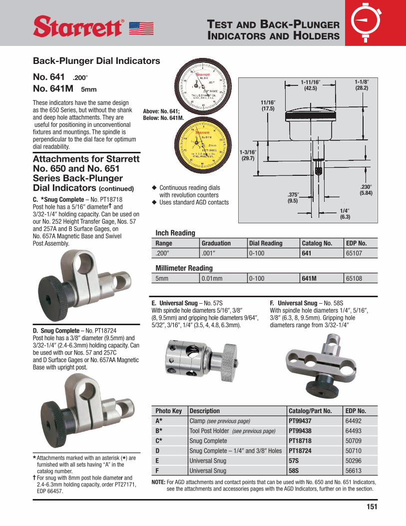
No. 641 .200�
No. 641M 5mm
These indicators have the same design as the 650 Series, but without the shankand deep hole attachments. They areuseful for positioning in unconventional
fixtures and mountings. The spindle isperpendicular to the dial face for optimumdial readability.
Photo Key Description Catalog/Part No. EDP No.
A* Clamp (see previous page) PT99437 64492
B* Tool Post Holder (see previous page) PT99438 64493
C* Snug Complete PT18718 50709
D Snug Complete – 1/4� and 3/8� Holes PT18724 50710
E Universal Snug 57S 50296
F Universal Snug 58S 56613
NOTE: For AGD attachments and contact points that can be used with No. 650 and No. 651 Indicators,see the attachments and accessories pages with the AGD Indicators, further on in the section.
* Attachments marked with an asterisk (*) arefurnished with all sets having “A” in thecatalog number.
† For snug with 8mm post hole diameter and2.4-6.3mm holding capacity, order PT27171,EDP 66457.
TEST AND BACK-PLUNGERINDICATORS AND HOLDERS
Attachments for StarrettNo. 650 and No. 651Series Back-PlungerDial Indicators (continued) ◆ Continuous reading dials
with revolution counters◆ Uses standard AGD contactsC. *Snug Complete – No. PT18718
Post hole has a 5/16� diameter† and 3/32-1/4� holding capacity. Can be used onour No. 252 Height Transfer Gage, Nos. 57and 257A and B Surface Gages, on No. 657A Magnetic Base and Swivel Post Assembly.
D. Snug Complete – No. PT18724Post hole has a 3/8� diameter (9.5mm) and3/32-1/4� (2.4-6.3mm) holding capacity. Canbe used with our Nos. 57 and 257C and D Surface Gages or No. 657AA MagneticBase with upright post.
E. Universal Snug – No. 57SWith spindle hole diameters 5/16�, 3/8�(8, 9.5mm) and gripping hole diameters 9/64�,5/32�, 3/16�, 1/4� (3.5, 4, 4.8, 6.3mm).
F. Universal Snug – No. 58SWith spindle hole diameters 1/4�, 5/16�,3/8� (6.3, 8, 9.5mm). Gripping holediameters range from 3/32-1/4�
Back-Plunger Dial Indicators
1-11/16�(42.5)
1-1/8�(28.2)
.230�(5.84)
1/4�(6.3)
.375�(9.5)
11/16�(17.5)
1-3/16�(29.7)
Inch ReadingRange Graduation Dial Reading Catalog No. EDP No.
.200� .001� 0-100 641 65107
Millimeter Reading5mm 0.01mm 0-100 641M 65108
Above: No. 641;Below: No. 641M.
152
TEST AND BACK-PLUNGERINDICATORS AND HOLDERS
**For Contact Points with #4-48 Thread, see AGD Contact Listings.
Contact Points and Adaptors OnlyDescription Catalog/Part No. EDP No.Adaptor** 196R 50711Adaptor (Metric Threads) 196MR 67457Hardened Steel PT05471 70617
PT05472 70618Contact Point PT05473 70619
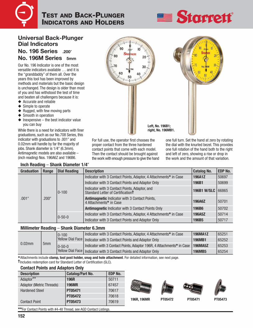
Universal Back-PlungerDial IndicatorsNo. 196 Series .200�
No. 196M Series 5mm
Our No. 196 Indicator is one of the mostversatile indicators available … and it is the “granddaddy” of them all. Over theyears this tool has been improved bymethods and materials but the basic designis unchanged. The design is older than mostof you and has withstood the test of timeand beaten all challengers because it is:◆ Accurate and reliable◆ Simple to operate◆ Rugged, with few moving parts◆ Smooth in operation◆ Inexpensive – the best indicator value
you can buyWhile there is a need for indicators with finergraduations, such as our No.708 Series, thisindicator with graduations to .001� and0.02mm will handle by far the majority ofjobs. Shank diameter is 1/4� (6.3mm).Antimagnetic models are also available –(inch reading) Nos. 196A6Z and 196B6.
Inch Reading – Shank Diameter 1/4�
Graduation Range Dial Reading Description Catalog No. EDP No.Indicator with 3 Contact Points, Adaptor, 4 Attachments* in Case 196A1Z 50697Indicator with 3 Contact Points and Adaptor Only 196B1 50699Indicator with 3 Contact Points, Adaptor, and 196B1 W/SLC 668650-100 Standard Letter of Certification†
.001� .200� Antimagnetic Indicator with 3 Contact Points,196A6Z 507014 Attachments* in Case
Antimagnetic Indicator with 3 Contact Points Only 196B6 50702
0-50-0Indicator with 3 Contact Points, Adaptor, 4 Attachments* in Case 196A5Z 50714Indicator with 3 Contact Points and Adaptor Only 196B5 50717
Millimeter Reading – Shank Diameter 6.3mm0-100 Indicator with 3 Contact Points, Adaptor, 4 Attachments* in Case 196MA1Z 65251
0.02mm 5mmYellow Dial Face Indicator with 3 Contact Points and Adaptor Only 196MB1 65252
0-50-0 Indicator with 3 Contact Points, Adaptor 196R, 4 Attachments* in Case 196MA5Z 65253Yellow Dial Face Indicator with 3 Contact Points and Adaptor Only 196MB5 65254
*Attachments include clamp, tool post holder, snug and hole attachment. For detailed information, see next page.† Includes redemption card for Standard Letter of Certification (SLC).
For full use, the operator first chooses theproper contact from the three hardened contact points that come with each model.Then the contact should be brought against the work with enough pressure to give the hand
one full turn. Set the hand at zero by rotating the dial with the knurled bezel. This provides one full rotation of the hand both to the rightand left of zero, showing a rise or drop inthe work and the amount of that variation.
PT05472196R, 196MR PT05471 PT05473
Left, No. 196B1;right, No. 196MB1.

153
TEST AND BACK-PLUNGERINDICATORS AND HOLDERS
C*
A. *Clamp – No. PT99437With a 1-5/16� (33mm) flat or roundcapacity, 5/16� (8mm) post used with No. PT18718 Snug.
B. *Tool Post Holder – No. PT994383/8� x 3/4� x 6� (9.5 x 19 x 150mm) withupright spindle 5/16� dia. x 4-1/2� length(8 x 114mm). Use with No. PT18718 Snug.
C. *Snug Complete – No. PT18718Post hole has a 5/16� diameter† and 3/32-1/4� holding capacity. Can be used onour No. 252 Height Transfer Gage, Nos. 57and 257A and B Surface Gages, on No. 657A Magnetic Base and Swivel Post Assembly.
D. Snug Complete – No. PT18724 Post has a 3/8� diameter (9.5mm) and 3/32-1/4� (2.4-6.3mm) holding capacity. Canbe used with our Nos. 57 and 257C and DSurface Gages and No. 657AA MagneticBase with upright post.
Photo Key Description Catalog/Part No. EDP No.
A* Clamp PT99437 64492
B* Tool Post Holder PT99438 64493
C* Snug Complete PT18718 50709
D Snug Complete – 1/4� and 3/8� Holes PT18724 50710
E* Hole Attachment 196F 50706
F Shock Absorbing Anvil PT08726A 66052
G Universal Snug 57S 50296
H Universal Snug 58S 56613
I Split Bushing PT00764 68850
NOTE: For AGD attachments and contact points that can be used with No. 196 Indicators, see theattachments and accessories pages with the AGD Indicators, further on in the section.
* Attachments marked with an asterisk (*) arefurnished with all sets having “A” in thecatalog number.
† For snug with 8mm post hole diameter and2.4-6.3 mm holding capacity, order PT27171,EDP 66457.
D
E. *Hole Attachment – No. 196FLets indicator be used over obstructions andinside holes to a depth of approximately 1-5/8� (40mm).
F. Shock Absorbing Anvil – No. PT08726A
G. Universal Snug – No. 57SWith spindle hole diameters 5/16�, 3/8�(8, 9.5mm) and gripping hole diameters9/64�, 5/32�, 3/16�, 1/4� (3.5, 4, 4.8,6.3mm).
Attachments for Starrett Nos. 196, 196M Series Universal Dial IndicatorsH. Universal Snug – No. 58SWith spindle hole diameters 1/4�, 5/16�,3/8� (6.3, 8, 9.5mm). Gripping holediameters range from 3/32-1/4�(2.4-6.3mm).
I. Split Bushing – No. PT00764Allows attachment of No. 196 Indicator toNo. 660 Magnetic Base.

154
TEST AND BACK-PLUNGERINDICATORS AND HOLDERS
Magnetic BaseIndicator HolderNo. 657AAFor use with all Starrett Test, Back-Plunger,AGD, Dial and Miniature-Dial Indicators.Also accommodates similar indicators of other manufacturers.
A. No. 657P Magnetic Base. 1-15/16 x 1-5/8 x 1-7/8� (50 x 40 x 48mm).Push-button on/off switch for one-handoperation. Base has three precision groundmagnetic contact points. Grips horizontally,vertically, and upside down. V-step holdsbase to arbors, shafts, etc. Base has extra1/4-20 tapped hole on one side formounting post. Black wrinkle finish on non-working surfaces.
B. No. 657G Upright Base Post. 3/8�(9.5mm) diameter x 7-7/16� (190mm)length overall. Starrett No. 57S and No. 58SUniversal Snugs may also be used.
C. No. 657S Snug. Two 1/4� (6.3mm)diameter holes. Adapts Nos. 196, 650, and651 Series Dial Indicators and No. 657YIndicator Attachment to No. 657X Rod.
D. No. 657X Rod. 1/4� (6.3mm) diameter x6� (150mm) long. Accommodates StarrettNos. 708, 709, 811 and 711F Series DialTest Indicators and No. 657S Sleeve.
E. No. 657Y Indicator Attachment. 1/4�(6.3mm) O.D. one end, other end threadedand fits lug backs of all AGD indicators(Starrett Series Nos. 81, 25, 655, 656) andSeries No. 80 Miniature Indicators.
F. No. PT18724 Snug 3/8� (9.5mm)diameter post hole. 1/4� (6.3mm) diametergripping hole accommodates No. 657X Rod.
Test and Back-PlungerIndicator HoldersTest and back-plunger indicatorscannot be used without properholders. The following pages showthe variety of Starrett holdersavailable. This selection shouldhandle virtually any job that needs to be done.
Packed one in a box.
A
B
F
D
E
C
No. 657AA.
Shown with No. 196B1 Universal Dial Indicator.
No. 657AA with No. 711FS LastWord Dial Test Indicator.
No. 657YIndicatorAttachmentshown with lug-on-center back.
Complete SetPhoto Key Description Catalog No. EDP No.
Magnetic Base with All Attachments – A, B, C, D, E, F 657AA 52743
Base and Post Assembly with No. 650B1 657-650Z 65259Indicator, No. 657S Snug, and 3 Contact Points
Individual ComponentsA Magnetic Base Only 657P 52757
B 7 7/16� Upright Base Post Only 657G 52753
C Snug with Two 1/4� (6.3 mm) Holes 657S 52759
D Rod 657X 52764
E Indicator Attachment 657Y 52765
F Snug Complete – 1/4� and 3/8� Holes PT18724 50710

155
TEST AND BACK-PLUNGERINDICATORS AND HOLDERS
Magnetic BaseIndicator Holder withswivel post assemblyNo. 657AThe swivel post assembly on these holdersprovides universal adjustment in bothhorizontal and vertical planes. Available withinch or millimeter Starrett Dial Test or Back-Plunger Indicators, they save time in shopset-up and other inspection jobs.
For use with all Starrett Test, Back-Plunger,AGD, Dial and Miniature-Dial Indicators.Also accommodates similar indicators ofother manufacturers.
Powerful, permanent magnetic base holdsfirmly to steel or iron surfaces – horizontally,vertically, upside-down. Push-button turnsmagnetic force on or off for quick, one-handset-up and take-down. V-step adapts baseto horizontal or vertical arbors and chucks.There is an extra 1/4-20 NC tapped hole inside of base for indicator mounting post.Three precision ground magnetic contactsurfaces (plus V-step). Black wrinkle finishon non-working surfaces.
Magnetic Base Assembly Features:
A. No. 657P Magnetic Base is 1-15/16� x1-5/8� x 1-7/8� (50 x 40 x 48mm) deep.
B. Swivel Cap Slot permits 90º posttravel to horizontal position.
A
B
E
GF
D
C
Individual ComponentsDescription Catalog No. EDP No.
Magnetic Base with Swivel Post Assembly 657A 52744
Magnetic Base Only 657P 52757
Swivel Post Assembly Only 657F 52752
Left, No. 657A shown with No.196B1 Universal DialIndicator setting up workpiece on milling machine.Center,No. 657A with No. 711LS Last Word Dial Test Indicatorsetting up workpiece on surface grinder. Right, No. 657A.
Packed one in a box.
C. Post rotates 360º.
D. No. 657F Indicator Swivel PostAssembly is 6-1/2� (165mm) high (less threaded end). Assembly consists ofitems B, C, E, F, G.
E. Fine-Adjusting Screw. Turn to zero set indicator.
F. Upper arm is 2� (50mm) long with a5/16� (8 mm) dia. and swings more than180º; friction joint holds it in position.
G. 7/32� (5.5mm) dia. step, 1/2�(13 mm) long.
Inch Reading SetsW/Finished Wood Case Without Case
Description* Cat. No. EDP No. Cat. No. EDP No.
Base and Post Assembly with 711FSAZ657BZ 52746 657B 52745Last Word® Indicator and PT07101F Body Clamp
Base and Post Assembly with 196B1 Indicator, PT18718657CZ 52748 657C 52747Snug, 3 Contact Points, and Contact Point Adaptor
Base and Post Assembly with 709AZ Indicator657-709Z 65257and PT22428 Swivel Post Snug
Base and Post Assembly with No. 811-1Z Indicator and657-811Z 65258PT22428 Swivel Post Snug
Millimeter Reading SetsBase and Post Assembly with 711MFSZ Indicator with
657MBZ 56354 657MB 56353PT07101F Body Clamp
Base and Post Assembly with 196MB1 Indicator,657MCZ 56356 657MC 56355PT18718 Snug, 3 Contact Points, Contact Point Adaptor
No. 657 Series Sets These sets have been put togetherfor your ordering convenience, butyou can mix and match other Starrettest or back-plunger indicators andattachments with the No. 657AMagnetic Base and Swivel PostAssembly to suit your needs.
With No.709A.
With No.711FS.
With No.196B1.
* See previous pages for detailed indicator and attachment specifications.

156
No. 657T SeriesFor use with all Starrett Test, Back-Plunger,AGD, Dial, and Miniature Dial Indicators.Also accommodates similar indicators ofother manufacturers. The flexible post is anassembly of short tubular steel sectionsand precision ball joints, linked by aninternal steel cable. It can be adjusted toany position and locked by turning a levernear the magnetic base. This makes itpossible to use indicators in awkwardplaces that are hard to reach withconventional holding devices.
Assembled to the magnetic base, the posthas a vertical reach of approximately 15�(380mm) and a horizontal reach ofapproximately 10� (250mm). The indicatorsnug on the end of the post can be rotatedthrough 360º and locked in any position.
The base has three precision groundmagnetic contact surfaces. Gripshorizontally, vertically or upside down.V-step holds base to arbors, shafts, chucks.
The No. 657W Attachment allows fineadjustments to be made, operated by turning the fine-adjusting thumb screw (with post locked in rigid position) to zero,then set the indicator.
A. Gage Rod 3/8� x 3� (9.5mm x 75mm)has 5/16, 1/4 and 7/32� (8, 6.3, and5.5mm) steps. Holds Nos. 708, 709, 711and 811 Dial Test Indicators by body clamp.See attachment specifications for theappropriate indicator body clamp onprevious pages.
B. Adjusting Take-up Sleeve with lockingnut for maintaining proper degree of postrigidity.
C. Post Snug has 3/8� (9.5mm) hole(which will also grip AGD dial indicators by the stem).
D. Flex-O-Post No. 657U.
E. Locking Lever tightens internal steelcable to make post rigid and lock it inposition.
F. Magnetic Base No. 657P has push-button on/off switch.
Packed one in a box.
Complete AssembliesDescription Catalog No. EDP No.
Magnetic Base with Flex-O-Post Assembly 657T 52760
Magnetic Base with Flex-O-Post Assembly and 657TW 52761Fine-Adjustment Attachment
Individual ComponentsPhoto Key Description Catalog No. EDP No.
F Magnetic Base Only 657P 52757
(A, B, C, D, E) Flex-O-Post with Locking Lever and Snug Only 657U 52762
G Fine-Adjustment Attachment 657W 52763
A Indicator Holding Rod PT17850 72400
Top inset, No. 651B1 Indicator gripped directly to its stem via the post snug; middle, holding aNo. 196B1 Indicator via a No. 657S Snug attached to the indicator’s 1/4� (6.3 mm) diameter rod;bottom, No. 657W Fine-Adjustment Attachment.
A
F
E
D
B
C
G
TEST AND BACK-PLUNGERINDICATORS AND HOLDERS
Flex-O-Post Indicator Holders with magnetic base

157
Packed one in a box.
Nos. 657-1 and -2 SeriesThis versatile indicator holder has threepivots available for positioning the indicatorwhere needed. All pivots are controlled byone tightening knob. It will hold:◆ Any indicator with a 3/8� (9.5mm) stem
(such as our No. 25 and Nos. 650 and651 Series)
◆ Any indicator with a standard dovetailmount (such as our Nos. 708, 709, and811 Series)
◆ Any indicator with a 1/4� (6.3mm) shank(such as our No. 196 Series)
◆ Any indicator with a 3/16� (4.7mm)shank (such as our Nos. 708, 709, 811and 711 Series)
◆ Any indicator with a body clamp (suchas our No. 711 Series)
◆ The working area is within ahemisphere having a radius ofapproximately 12� (300mm)
Individual ComponentsPhoto Key Description Catalog No. EDP No.
A Universal Indicator Holder Arm Assembly Only 657-3 64438
B Fine-Adjustment Attachment 657W 52763
C Indicator Holding Rod PT17850 72400
D Magnetic Base Only 657P 52757
E Snug with Two 1/4� (6.3 mm) Holes 657S 52759
Complete AssembliesDescription Catalog No. EDP No.
Universal Indicator Holder, No. 657W Fine-Adjustment,No. 657P Magnetic Base, No. PT17850 Indicator Holding Rod, 657-1 64436and No. 657S Snug
Universal Indicator Holder with No. 657 Magnetic Base 657-2 64437
A
B
D
E
C
Above: No. 709A Dial TestIndicator with dovetail mount.
TEST AND BACK-PLUNGERINDICATORS AND HOLDERS
Magnetic Base Universal Indicator Holder with triple-jointed arm and fine-adjustment
B. Any of our great variety of height gages.Series Nos. 250, 254, 255, 259, and3752. These can be used for comparingand for actual vertical measurements
C. Our No. 57 or No. 257 Surface Gages.These are for comparison and thetruing-up of surfaces
A
B C
References for OtherTest Indicator HoldingMethodsIn addition to the magnetic base indicatorholders on the preceding pages, we alsooffer the following:A. For very precise measurements such as
comparing a part to a gage block set,we have our No. 252 Height TransferGage with our Digi-Chek® Series ofHeight Gages
◆ The very sensitive fine-adjustment is located on themagnetic base to eliminateindicator deflection when it is being adjusted
◆ The No. 657-3 UniversalIndicator Holder Arm Assemblycan also be used on the No.659P Base using the No. 659Thread Adaptor, No. PT18318
No. 657-1.
Above:No. 657-1 shown with No.196B1 Universal Dial Indicator.

158
Magnetic BaseIndicator Holder withTriple-Jointed ArmNo. 660 The compact and versatile 660 magneticbase indicator holder has three adjustablepivots controlled by a single knob for fast,easy indicator positioning.
◆ Small but powerful magnetic base, with70 lbs. (320 N) holding force
◆ Positive On/Off switch◆ Base Dimensions: 1-3/16� x 1-9/16� x
1-3/8� (30mm x 40mm x 35mm)◆ Horizontal and vertical mounting
positions◆ Will hold any indicator with a 3/8�
(9.5mm) stem or standard dovetailmount
◆ Articulating arm with powerful centrallocking knob, provides full 360ºhorizontal positioning and over 180ºvertical positioning
◆ Maximum Horizontal Reach: 4.750�(120mm); Maximum Vertical Reach:7.500� (190mm)
◆ Very sensitive fine-adjustment thumbscrew
Description Catalog No. EDP No.
Base Indicator Holder 660 68621
Left, No. 660. Inset, No. 660 shown with 81-131JDial Indicator.
TEST AND BACK-PLUNGERINDICATORS AND HOLDERS
CA
D
BCommon Test andBack-Plunger Indicator ApplicationsA. Models with tool post holders,
generally used for lathe work.B. Indicators may be used on our
No. 665 inspection holder.B, C. Some indicator holders have clamps
for holding in different places.C, D. Indicators with straight
stems or shanks can beheld in snugs or inchucks and collets.

Mechanical Dial Indicators and AttachmentsElectronic Indicators Indicator HoldersAccurate, rugged, versatile, convenient to use and inexpensive—for these reasons and more,mechanical dial indicators withbottom plungers are the measurement workhorses of industrialproduction.
Electronic indicators have an unmatched ability for the accuraterecording of a great amount of measurement data which is usedin a variety of Statistical Process Control (SPC) operations.
The first part of this section shows our complete line ofmechanical/analog dial indicators – over 180 models to give youthe widest selection in the industry. Our comparison guide,following these introduction pages, has all the significantspecifications to help you make your selection.
Application Specification Factors1. Regular analog styles with indicating hands are more readable
than digital styles when the measurements are being visuallymonitored by an operator.
2. Select the dial size that gives you the readability you need. Weoffer five regular dial sizes which will fit most applications thathave both space limitations and readability requirements.
3. Choose the accuracy and readout you need – don’t select a.0001� (or 0.001mm) readout if .001� (or 0.01mm) will do yourjob.
4. Electronic styles are best when the measurement data needsto be collected, printed out or stored for future use.
5. Consider any special features you may need – inch or millimeter reading, special shockless movement,antimagnetic, long range, long stem, special backs, specialcontacts, special holders, etc. If you don’t see what you need,please contact our Special Order Department. Even though wehave a broad line of indicators to tackle most jobs, we also doa lot of special design, catering to the specific needs of ourcustomers – challenge us!
6. Starrett indicators are made to American Gage DesignSpecifications (AGD). These specifications were developed in1945 at the request of the U.S. Commerce Departmentthrough the National Bureau of Standards – now the NationalInstitute of Standards and Technology (NIST). Thesespecifications provide the dimensions to allowinterchangeability between indicators of differentmanufacturers in fixturing. As you will see, these dimensionspertain to sizes for space consideration and for holding. Othercountries have made their own design specifications which wecan also furnish. However, the AGD design is probably morewidely used, simply because it was the first standard created.
7. Basically, all dial indicators used worldwide fall into thefollowing size ranges which relate to bezel diameters. Size 0 isa smaller dial indicator, having its own dimensions. Sizes 1through 4 are AGD sizes. These sizes and the AGD dimensions
Bezel Diameters
Size Minimum Diameter Maximum Diameter
Group Inch mm Inch mm
0 1� 25mm 1-3/8� 35mm
1 1-3/8� 35mm 2� 50mm
AGD 2 2� 50mm 2-3/8� 60mm
3 2-3/8� 60mm 3� 75mm
4 3� 76mm 3-3/4� 95mm
*There are two major differences between American Gage Design and other specifications. The first is the stem diameter. AGD specifies .375�(9.5mm) and some other standards specify an 8mm (.315�) diameter.International specifications allow for either one and we can furnish bothdiameters. The .375� (9.5mm) diameter provides a little more protection forthe rack when clamped on the stem – 8mm stems are available on anymodel, please specify when ordering.
**The other difference is the contact thread. AGD specifies a #4-48 thread.Other standards specify a metric thread, #M2.5.
1/4�(6.35)
3/4�(19)
1/4�(6.35)
1/4�(6.35)
.375�(9.5)*
#4-48(M 2.5)THREAD**
Comparing AGD Design Specifications with Others
are essentially the same for all manufacturers, except asnoted.
8. Accuracy – All indicators should be “loaded” 1/8-1/4 of a turnbefore testing or measuring. Starrett dial indicators meet orexceed all known performance specifications. Most accuraciesare specified plus or minus one graduation over the full range.This basically means a 2-1/2 turn range. Longer ranges haveslightly wider tolerances. Starrett indicators are at least thataccurate, but we are better than that in the final criticalmeasuring zone of “10 o’clock to 2 o’clock” from zero.AGD specifies 2-1/3 turn indicators to cover any particularrange. The reason for this is that in an effort to get the most outof the indicator, the operator “loads” it to about 1-1/3 turns andsets zero on his master. The indicator will now show theaccurate deviation for a full revolution, plus or minus.
159
DIAL AND ELECTRONICINDICATORS AND HOLDERS
The AGD Design Specifications

J.W. DONCHIN CO. 4841-43 W. Chicago Ave. • Chicago, IL 60651-3224Ph: 773-261-2182 • Fax: 773-261-2867 • [email protected] • www.jwdonchin,com
Dial and Electronic Indicators and Holders
159 Dial & Electronic Indicators and Holders Introduction
160 Starrett Dial Indicator Design Features
161 Dials, Accessories and Options
162 Miniature Dial Indicators Series No. 80
163 Miniature No. 80 Dial Indicator Accessories No. 80 Series
164 Series 81, 25, 655 and 656 AGD Dial Indicators
165 Series 81, 25, 655 and 656 AGD Dial Indicators
166 Starrett Dial Numbering and Line Styles for Dial Indicators
167 Starrett Dial Numbering and Line Styles for Dial Indicators
168 Starrett Dial Numbering and Line Styles for Dial Indicators
169 Starrett Dial Numbering and Line Styles for Dial Indicators
170 Dial Indicators AGD Group 1 Series No. 81
171 Dial Indicators AGD Group 1 with double row figures Series No. 81
172 Dial Indicators Series No. 25
173 Dial Indicator Sets Series No. 253
174 Dial Indicators Series No. 655
175 Dial Indicators Series No. 655
176 Dial Indicators with long range Series No. 656
177 Dial Indicators with long range Series No. 656
178 Metric Dial Indicators with long range Series No. 25, 655, 656
179 Dial Indicators with extra-long range Series No. 25, 656
180 Dial Indicators with extra-long range AGD Group 4 Series No. 656
181 AGD Dial Indicator Backs - Indicator Backs
182 Backs with adjustable mounting bracket Series No. 674
Universal Backs Series No. 672
Magnetic Backs Series No. 676
Continued next page

183 Indicator Hole Attachment Series No. 670
Universal Attachment Series No. 671
184 AGD Indicator Contact Points and Accessories Series No. 28
AGD Indicator Contact Points and Accessories Series No. Extra-Length Cont.Points
AGD Indicator Contact Points and Accessories Series No. Cont. Points
Flat-End Steel Contact Points Series No. Contact Points
185 AGD Indicator Special Contact Points and Accessories Series No. 25R
AGD Indicator Special Contact Points and Accessories Series No. 25W
AGD Indicator Special Contact Points and Accessories Series No. Cont. Adaptor
AGD Indicator Special Contact Points and Accessories Series No. Special Form Cont.Points
AGD Indicator Special Contact Points and Accessories Series No. Contact Ext
AGD Indicator Accessories Series No. 25MSB, 25SB, 80SB
186 AGD Indicator Accessories Series No. 25SC
187 AGD Indicator Accessories Series No. 25LC
AGD Indicator Accessories Series No. Dust Guard
188 AGD Indicator Accessories - Series No. LeverControl
189 Indicator Testers Series No. 716, 716M
190 Electronic Indicators Series No. 2600
191 Electronic Indicators Series No. 2600
192 WISDOM Electronic Indicators Series No. 2700
193 WISDOM Series Remote Displays and Probes Series No. 2700
194 WISDOM Series Remote Displays and Probes Series No. 2700
195 No. 3600 Series AGD Group 2
196 Magnetic Base Indicator Holder and Indicators - Series No. 657
197 Heavy-Duty Magnetic Base Indicator Holder Series No. 659
198 Inspection Holder and Starrett AGD Dial Indicators Series No. 665
199 Inspection Holder and Starrett AGD Dial Indicators Series No. 665
200 Dial Comparators with granite base Series No. 675
201 Dial Comparators Series No. 653
202 Dial Bench Gages Series No. 652
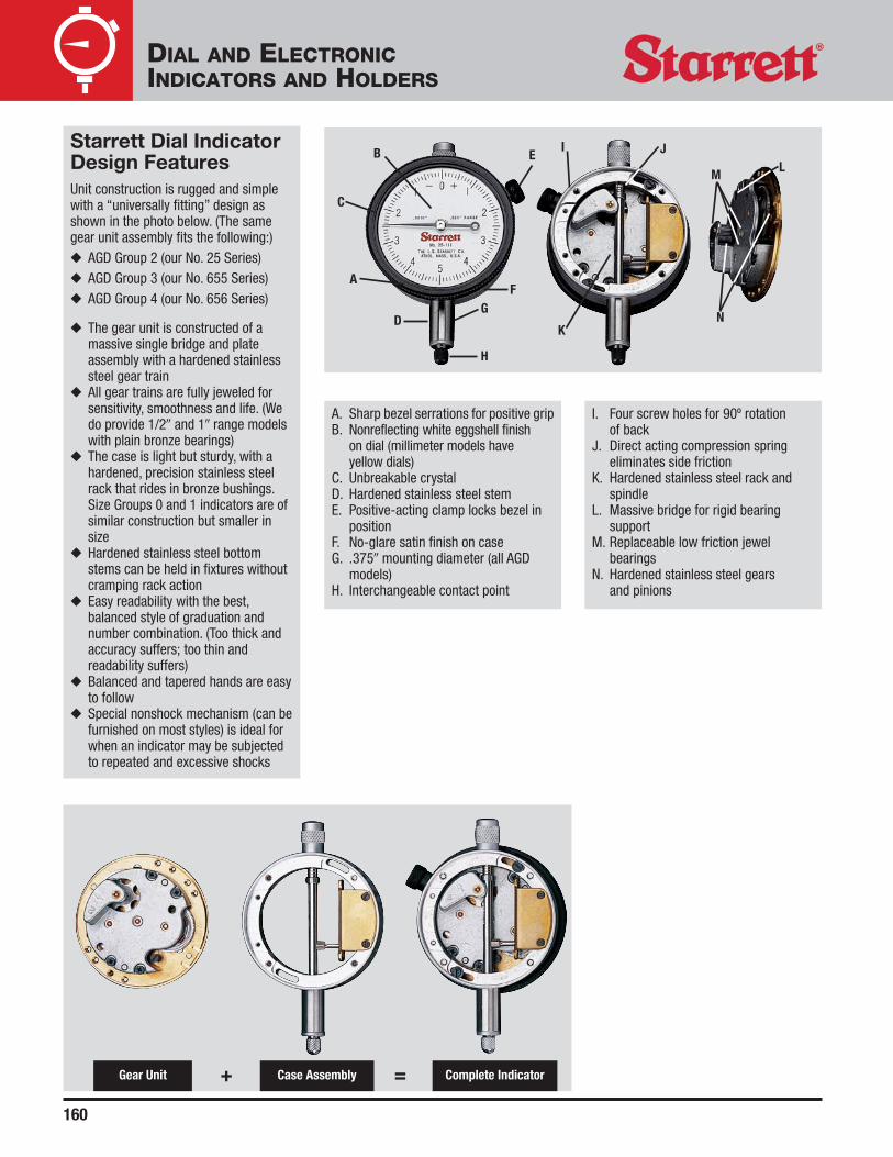
A. Sharp bezel serrations for positive gripB. Nonreflecting white eggshell finish
on dial (millimeter models have yellow dials)
C. Unbreakable crystalD. Hardened stainless steel stemE. Positive-acting clamp locks bezel in
positionF. No-glare satin finish on caseG. .375� mounting diameter (all AGD
models)H. Interchangeable contact point
I. Four screw holes for 90º rotation of back
J. Direct acting compression springeliminates side friction
K. Hardened stainless steel rack andspindle
L. Massive bridge for rigid bearingsupport
M. Replaceable low friction jewelbearings
N. Hardened stainless steel gears and pinions
Starrett Dial IndicatorDesign FeaturesUnit construction is rugged and simplewith a “universally fitting” design asshown in the photo below. (The samegear unit assembly fits the following:)◆ AGD Group 2 (our No. 25 Series)◆ AGD Group 3 (our No. 655 Series)◆ AGD Group 4 (our No. 656 Series)
◆ The gear unit is constructed of amassive single bridge and plateassembly with a hardened stainlesssteel gear train
◆ All gear trains are fully jeweled forsensitivity, smoothness and life. (Wedo provide 1/2� and 1� range modelswith plain bronze bearings)
◆ The case is light but sturdy, with ahardened, precision stainless steelrack that rides in bronze bushings.Size Groups 0 and 1 indicators are ofsimilar construction but smaller insize
◆ Hardened stainless steel bottomstems can be held in fixtures withoutcramping rack action
◆ Easy readability with the best,balanced style of graduation andnumber combination. (Too thick andaccuracy suffers; too thin andreadability suffers)
◆ Balanced and tapered hands are easyto follow
◆ Special nonshock mechanism (can befurnished on most styles) is ideal forwhen an indicator may be subjectedto repeated and excessive shocks
Complete IndicatorCase AssemblyGear Unit + =
L
IE
F
J
KD
B
C
A
H
GN
M
160
DIAL AND ELECTRONICINDICATORS AND HOLDERS

◆ Revolution Counters – All AGD indicators with 2-1/2 revolutionscan be furnished with double dial and count hand at a slightadditional cost. Intermediate and long-range indicators haverevolution counters
◆ Special Dials – Starrett dial indicators can be furnished withany standard dial marked with your company name ortrademark. There is no charge when the indicators arepurchased in lots of 25 or more. For quantities under 25, there isan additional charge. Prices are available on request
◆ Antimagnetic Mechanism – An antimagnetic mechanism canbe furnished on most Series Nos. 81, 25, 655 and 656 DialIndicators (and also on our No. 196B6 Universal Dial Indicator).This mechanism is desirable when the indicator is used near amagnetic chuck or a similar magnetic field which would disturbits operation. See individual listings for availability
◆ Attachments and Accessories – A variety of attachments andaccessories are provided for mounting dial indicators onmachine tools, inspection equipment and special fixtures These include:◆ Backs◆ Contact Points◆ Dust Guard◆ Hole Attachments◆ Special Nonshock Mechanism◆ Spindle Travel Controls◆ Stem and Back Mounting Accessories◆ Tolerance and Maximum Reading Hands
Dials, Accessories and Options◆ Balanced or Continuous Dials – Starrett AGD indicators are
available with a balanced dial (plus on right) or a continuous dial (reading clockwise). A balanced dial is sent unless otherwise ordered
◆ Plus and Minus Graduations – Plus and minus readout – black figures read clockwise, red figures read counterclockwise,or colors reversed – are available on some No. 81 Series Dial Indicators
Balanced Dial Continuous Dial
Dial with Plus andMinus Graduations
Dial with SpecialTrademark Imprint
161
DIAL AND ELECTRONICINDICATORS AND HOLDERS

162
Range
Graduation One Rev. Total Dial Reading Catalog No. EDP No.
.0001�.004� .010� 0-2-0 80-114J 55891
.010� .025� 0-5-0 80-111J 67714
.0005� .020� .050� 0-10-0 80-134J 55892
.001� .040� .100� 0-20-0 80-144J 55893
Miniature DialIndicatorsNo. 80 Series ANSI Group 0Ranges up to .100�
1-1/4� bezel, 7/32� stem
Similar in design to AGD dial indicators,these miniatures are built for gagingdimensions in tight places. Equipped withhigh precision, low friction movements, theyare made in four models, all with frictionallyadjustable bezels for quick, positive zerosetting. No-glare, white eggshell finish dials.Black bezel, silver finish on case. Furnishedwith balanced dial, jeweled bearings andlug-on-center back.
Packed one in a box. See following page for information on contact points and backs.
1/4� (6.3)
9/16� (14.5)
Dimensions with lug-on-center back
Free drafting template available for this size. Write The L. S. Starrett Co., Athol, MA 01331.
15/64� (6)
19/32�(15)
1-3/16�(30)
1/8� (3)
Left-to-right: No. 80-114J, No. 80-134J, No. 80-144J.
No. 80-111J..2185� (5.5)
1-1/8�(30)1-1/4�
(32)
7/32� (5.5)
1/4� (6.3)
3/4� (19)
DIAL AND ELECTRONICINDICATORS AND HOLDERS

163
Miniature Dial Indicator Accessories – No. 80 Series
Contact PointsThe regular contact point is furnished asstandard on all No. 80 Series DialIndicators. Button, cone and flat contactpoints are available individually, as listed.All have #0-80 thread.
1/8�DIA
BacksThe lug-on-center back is furnishedstandard on all No. 80 Series DialIndicators.
RegularPT2504472023
ConePT2516172025
FlatPT2516072026
ButtonPT2515972024
3/32�
3/32� R1/8�DIA 3/8� DIA
1/8�
1/4� R
7/16�
.015� R
1/8�DIA
1/4�
FlatPT2507972028
AdjustableBracketPT2515772029
Post-TypeLugPT2515872031
Screw-TypeLugPT2507172030
Lug-on-CenterPT2505372027
1/4�
45º
1/2�
9/16�
1/4� DIA
1-1/8� DIA
#1/4-28THREAD
1/2� DIA
9/16�
11/16� DIA
#8-32THREAD
1/8�
3/8�1/4�
5/16�
3/8�
5/16� DIA
7/32� DIA
NOTE: Contact points and backs can be ordered individually. Order by part number/EDP number.
DIAL AND ELECTRONICINDICATORS AND HOLDERS

164
Inch Reading (White Dials Furnished Standard)Range
Graduation One Rev. Total Dial Reading No. 81 Series No. 25 Series No. 655 Series No. 656 Series
.00005� .006� .015�0-3-0 25-109 656-109
0-6 25-209 656-209
.006� .015� 0-3-0 25-116
.008� .020�0-4-0 25-118 655-118 656-118
0-8 25-218
.010� .025�0-5-0 81-111 25-111 655-111 656-111
0-10 81-211 25-211 655-211 656-211
.0001�+0.10 81-111-624*
.010� .025�–0.10
–0.10 81-111-630*+0.10
.010� .200�0-5-0 25-511* 655-511* 656-511*0-10 25-611* 655-611* 656-611*
.020� .400�0-10-0 656-517*0-20 656-617*
.010� .025�0-5-0 81-124 25-124 655-124 656-124
0-10 81-224 25-224 655-224 656-224
.00025� .020� .050�0-10-0 81-128 25-128 655-128 656-128
0-20 81-228 25-228 655-228 656-228
.030� .075�0-15-0 655-129 656-129
0-30 655-229 656-229
.020� .050�0-10-0 81-134 25-134 655-134 656-134
0-20 81-234 25-234 655-234 656-234
.030� .075�0-15-0 81-136 25-136 655-136 656-136
0-30 81-236 25-236 655-236 656-236
+0.30 81-136-622*–0.30
.0005�
.030� .075�–0.30 81-136-623*+0.30
.040� .100�0-20-0 81-138 25-138 655-138 656-138
0-40 81-238 25-238 655-238 656-238
.050� .125�0-25-0 81-131 25-131 655-131 656-131
0-50 81-231 25-231 655-231 656-231
.050�.500� 0-50 25-431*1.000� 0-50 25-631*
Series 81, 25, 655 and 656 AGD DialIndicatorsThis comparison table is an aid to help you find theindicator with the specific graduations and rangesyou are looking for. Refer to the following pages for the exact catalog number and EDP number.
(Continued on next page.)
Group 43-5/8�92mm
Group 32-3/4�70mm
Group 22-1/4�57mm
Group 11-11/16�43mm
➝ ➝ ➝ ➝➝ ➝ ➝ ➝
* With revolution counter on dial.
DIAL AND ELECTRONICINDICATORS AND HOLDERS

165
Inch Reading (White Dials Furnished Standard) (continued)Range Group 1 Group 2 Group 3 Group 4
Graduation One Rev. Total Dial Reading No. 81 Series No. 25 Series No. 655 Series No. 656 Series
.020� .050�0-10-0 81-142 25-142 655-142 656-1420-20 81-242 25-242 655-242 656-242
.030� .075�0-15-0 81-143 25-143 655-143 656-1430-30 81-243 25-243 655-243 656-243
.030� .075�+0.30, –0.30 81-142-628*–0.30, +0.30 81-143-629*
.040� .100�0-20-0 81-144 25-144 655-144 656-1440-40 81-244 25-244 655-244 656-244
.050� .125�0-25-0 81-145 25-145 655-145 656-1450-50 81-245 25-245 655-245 656-245
.100� .250�0-50-0 81-141 25-141 655-141 656-1410-100 81-241 25-241 655-241 656-241
.100� .500�0-50-0 25-341/5* 655-341/5* 656-341/5*0-100 25-441/5* 655-441/5* 656-441/5*
.001�.100� 1.000�
0-50-0 25-341* 655-341* 656-341*0-100 25-441* 655-441* 656-441*
2.000� 25-2041* 655-2041* 656-2041*3.000� 25-3041* 655-3041* 656-3041*4.000� 25-4041* 655-4041* 656-4041*5.000� 25-5041* 655-5041* 656-5041*6.000� 656-6041*
.100� 7.000� 0-100 656-7041*8.000� 656-8041*9.000� 656-9041*10.000� 656-10041*11.000� 656-11041*12.000� 656-12041*
Millimeter Reading (Yellow Dials Furnished Standard)
0.001mm 0.1mm 0.25mm0-50-0 25-151*0-100 25-251*
0.002mm 0.2mm 0.5mm0-10-0 81-161 25-161 655-161 656-1610-20 81-261 25-261 655-261 656-261
1mm 2.5mm0-50-0 81-181 25-181 655-181 656-1810-100 81-281 25-281 655-281 656-281
1mm 10mm0-50-0 25-381*0-100 25-481*
0.01mm 1mm 25mm0-50-0 25-781*0-100 25-881* 655-881* 656-881*
1mm 50mm 0-100 25-2081* 655-2081*1mm 75mm 0-100 25-3081* 655-3081*1mm 100mm 0-100 25-4081* 655-4081*1mm 125mm 0-100 25-5081* 655-5081*
* With revolution counter on dial.
DIAL AND ELECTRONICINDICATORS AND HOLDERS

166
Total Range .015�
Catalog No.No. 25-109No. 656-109
Total Range .015� .020� .025� .025�
No. 25-111No. 25-118 No. 80-111 No. 81-111-624
Catalog No. No. 25-116 No. 655-118 No. 81-111 (with double row figures)No. 656-118 No. 655-111
No. 656-111
Total Range .200� .400�
Catalog No.No. 25-511No. 655-511 No. 656-517No. 656-511
.00005� Graduation
.0001� Graduation
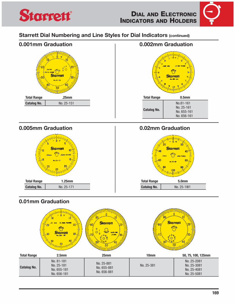
Starrett Dial Numbering and Line Styles for Dial Indicators These next four pages include all Starrett dial styles. (Actual sizenot shown.) Refer to the graduation, then range, and catalognumber below the dial and then see the following pages for thespecific dial reading and other indicator information. Most of thedials shown have balanced styles. Continuous dials have the same
graduations, but have consecutive numbers instead. For mostindicators, the first number after the base catalog number signifies dial style. The number “1” signifies balanced dials(example: No. 25-109) and number “2” signifies continuous dials (example: No. 25-209).
(Continued on next page.)
DIAL AND ELECTRONICINDICATORS AND HOLDERS

167
Total Range .025� .050� .075�
No. 81-124 No. 81-128
Catalog No.No. 25-124 No. 25-128 No. 655-129No. 655-124 No. 655-128 No. 656-129No. 656-124 No. 656-128
Total Range .050� .075� .075� .100�
No. 81-134 No. 81-136 No. 81-138
Catalog No.No. 25-134 No. 25-136 No. 81-136-622 No. 25-138No. 655-134 No. 655-136 (with double row figures) No. 655-138No. 656-134 No. 656-136 No. 656-138
Total Range .125� .500� 1.000�
No. 81-131
Catalog No.No. 25-131
No. 25-431 No. 25-631No. 655-131No. 656-131
.00025� Graduation
.0005� Graduation
(Continued on next page.)
Starrett Dial Numbering and Line Styles for Dial Indicators (continued)
DIAL AND ELECTRONICINDICATORS AND HOLDERS

168
Total Range .050� .075� .075� .100�
No. 81-142 No. 81-143 No. 81-144
Catalog No. *No. 25-142 No. 25-143 No. 81-143-628 *No. 25-144*No. 655-142 No. 655-143 (with double row figures) *No. 655-144*No. 656-142 No. 656-143 *No. 656-144
.001� Graduation
.005� Graduation
.010� Graduation
Total Range .500�
Catalog No. No. 25-500
Total Range 1.000�
Catalog No. No. 25-1000
Total Range .125� .250� .500�, 1.000�
No. 81-145 No. 81-141Nos. 25-441, 25-441/5
Catalog No. *No. 25-145 *No. 25-141Nos. 655-441, 655-441/5*No. 655-145 *No. 655-141Nos. 656-441, 656-441/5*No. 656-145 *No. 656-141
Starrett Dial Numbering and Line Styles for Dial Indicators (continued)
*Also on long range models.
(Continued on next page.)
DIAL AND ELECTRONICINDICATORS AND HOLDERS
Available from the Special Order Department.
169
0.001mm Graduation 0.002mm Graduation
0.01mm Graduation
Total Range 2.5mm 25mm 10mm 50, 75, 100, 125mm
No. 81-181No. 25-881
No. 25-2081
Catalog No. No. 25-181No. 655-881
No. 25-381 No. 25-3081No. 655-181
No. 656-881No. 25-4081
No. 656-181 No. 25-5081
Total Range 0.5mm
No.81-161
Catalog No.No. 25-161No. 655-161No. 656-161
Total Range .25mm
Catalog No. No. 25-151
Starrett Dial Numbering and Line Styles for Dial Indicators (continued)
0.005mm Graduation
Total Range 1.25mm
Catalog No. No. 25-171
0.02mm Graduation
Total Range 5.0mm
Catalog No. No. 25-1W1
DIAL AND ELECTRONICINDICATORS AND HOLDERS

170
Inch ReadingRange Dial
Graduation One Rev. Total Reading Catalog No. EDP No.
.0001� .010� .025�0-5-0 81-111J 53378
0-10 81-211J 53414
.010� .025�0-5-0 81-124J 53384
.00025�0-10 81-224J 53416
.020� .050�0-10-0 81-128J 53386
0-20 81-228J 53418
.020� .050�0-10-0 81-134J 53390
0-20 81-234J 53422
.030� .075�0-15-0 81-136J 53392
0-30 81-236J 53424.0005�
.040� .100�0-20-0 81-138J 53398
0-40 81-238J 53426
.050� .125�0-25-0 81-131J 53388
0-50 81-231J 53420
.020� .050�0-10-0 81-142J 53402
0-20 81-242J 53430
.030� .075�0-15-0 81-143J 53404
0-30 81-243J 53432
.001� .040� .100�0-20-0 81-144J 53408
0-40 81-244J 53434
.050� .125�0-25-0 81-145J 53410
0-50 81-245J 53436
.100� .250�0-50-0 81-141J 53400
0-100 81-241J 53428
Millimeter ReadingRange Dial Stem
Graduation One Rev. Total Reading Dia. Catalog No. EDP No.
0-10-0.375� 81-161J 56043
8mm 81-161J-8 646430.002mm 0.2mm 0.5mm
0-20.375� 81-261J 56045
8mm 81-261J-8 64644
0-50-0.375� 81-181J 53412
8mm 81-181J-8 646450.01mm 1.0mm 2.5mm
0-100.375� 81-281J 53438
8mm 81-281J-8 64646
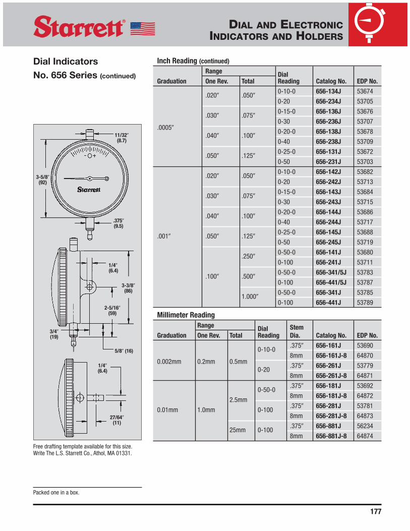
Dial IndicatorsNo. 81 Series AGD Group 1Ranges up to .250� and 2.5mm
These Indicators have a shockless,hardened steel gear train and jewelbearings. They are furnished with a lug-on-center back. Antimagnetic andspecial nonshock mechanisms are options available for all models. For more information on these and other attachments,accessories and contact points, refer to the end of the AGD Dial Indicator listings.For dial styles, see previous pages. Fordimensions, see next page.
Packed one in a box.
No. 81-141J.
No. 81-161J.
DIAL AND ELECTRONICINDICATORS AND HOLDERS

171
Dial Figures Range
Graduation Reading Direction Color One Rev. Total Catalog No. EDP No.
+0-10 Clockwise Black
–0-10Counter-
Red81-111-624J 53380
.0001�clockwise
.010� .025�
+0-10Counter-
Blackclockwise 81-111-630J 53382
–0-10 Clockwise Red
+0-30 Clockwise Black
–0-30Counter-
Red81-136-622J 53394
clockwise.0005�
+0-30Counter-
Blackclockwise 81-136-623J 53396
–0-30 Clockwise Red.030� .075�
+0-30 Clockwise Black
–0-30Counter-
Red81-143-628J 53406
.001�clockwise
+0-30 Counter- Blackclockwise 81-143-629J 66666
–0-30 Clockwise Red
NOTE: Other models with double-row figures can be furnished by request.
Dial IndicatorsNo. 81 Series withdouble row figuresAGD Group 1Ranges up to .075�
These indicators have the exact samefeatures as our No. 81 Series on theprevious page, except the dials havedouble-row figures, as illustrated on theright, and they cannot be specified with aspecial nonshock mechanism.
Free drafting template available for this size.Write The L.S. Starrett Co., Athol, MA 01331.
11/32� (8.7)
3/4� (19)
7/32� (5)
1/4� (6.3)
1/4�(6.3)
1/2� (12.7)
1-3/8�(35)
.375� (9.5)
1-11/16�(43)
1-1/2�(38)
5/8�(16)
Packed one in a box.
81-111-624J81-111-630J
81-136-622J
81-143-628J
81-136-623J
No. 81-111-624J.
81-143-629J
DIAL AND ELECTRONICINDICATORS AND HOLDERS

172
Inch Reading Models with Jewel BearingsRange Dial
Graduation One Rev. Total Reading Catalog No. EDP No.
.00005� .006� .015�0-3-0 25-109J 53222
0-6 25-209J 53254
.006� .015� 0-3-0 25-116J 53225
.008� .020�0-4-0 25-118J 53226
0-8 25-218J 53257
.0001�.025�
0-5-0 25-111J 53223
.010�0-10 25-211J 53255
.200�0-5-0 25-511J 53299
0-10 25-611J 53301
.010� .025�0-5-0 25-124J 53228
0-10 25-224J 53259.00025�
.020� .050�0-10-0 25-128J 53230
0-20 25-228J 53261
.020� .050�0-10-0 25-134J 53234
0-20 25-234J 53265
.030 .075�0-15-0 25-136J 53236
0-30 25-236J 53267
.0005� .040� .100�0-20-0 25-138J 53238
0-40 25-238J 53269
.125�0-25-0 25-131J 53232
25-231J 53263.050�
.500� 0-50 25-431J 53292
1.000� 25-631J 53304
.001� .020� .050�0-10-0 25-142J 53242
0-20 25-242J 53273
Dial IndicatorsNo. 25 Series AGD Group 2Ranges up to 1� and 25mm
These indicators have a shockless,hardened steel gear train and jewelbearings, except where noted. They arefurnished with a lug-on-center back. Anti-magnetic mechanism is optional for allmodels. Special nonshock mechanism is available for all models except Nos. 25-109,25-209 and 25-116. For more information on these and other attachments, accessoriesand contact points, refer to the end of theAGD Dial Indicator listings. For dial styles,see previous pages.
Packed one in a box.
2-1/4� (57)
11/32� (8.7)
.375� (9.5)
1/4� (6.3)
1/4� (6.3)
2-1/16� (52)
23/32� (18)
15/32� (12)
1-3/4� (44)
3/4� (19)
Free drafting template available for this size.Write The L.S. Starrett Co., Athol, MA 01331.
Left, No. 25-111J; right, No. 25-161J.
DIAL AND ELECTRONICINDICATORS AND HOLDERS

173
Inch Reading Models with Jewel Bearings (continued)
Range DialGraduation One Rev. Total Reading Catalog No. EDP No.
.030� .075�0-15-0 25-143J 532440-30 25-243J 53275
.040� .100�0-20-0 25-144J 532460-40 25-244J 53277
.050� .125�0-25-0 25-145J 53248
.001�0-50 25-245J 53279
.250�0-50-0 25-141J 532400-100 25-241J 53271
.100�0-50-0 25-341/5J 53285
.500�0-100
25-441/5J 5329325-441/5J W/SLC* 66864
0-50-0 25-341J 532871.000�
0-10025-441J 5329525-441/J W/SLC* 66863
Inch Reading Models with Plain Bearings
.500�0-50-0 25-341/5P 53286
.001� .100�0-100 25-441/5P 53294
1.000�0-50-0 25-341P 532880-100 25-441P 53296
Millimeter Models with Jewel BearingsRange Dial Stem
Graduation One Rev. Total Reading Dia. Catalog No. EDP No.
0-50-0.375� 25-151J 67644
0.001mm 0.1mm 0.25mm8mm 25-151J-8 68646
0-100.375� 25-251J 681188mm 25-251J-8 68647
0-10-0.375� 25-161J 532508mm 25-161J-8 64651
0.002mm 0.2mm 0.5mm0-20
.375� 25-261J 532818mm 25-261J-8 64652
0.02mm 2.0mm 5.0mm 0-100-0 .375� 25-1W1J 686420.005mm 0.5mm 1.25mm 0-25-0 .375� 25-171J 68643
0-50-0.375� 25-181J 532528mm 25-181J-8 64653
2.5mm0-100
.375� 25-281J 532838mm 25-281J-8 64654
0-50-0.375� 25-381J 53289
0.01mm 1.0mm 8mm 25-381J-8 6465510mm
0-100.375� 25-481J 532978mm 25-481J-8 64656
0-50-0.375� 25-781J 533058mm 25-781J-8 64657
25mm0-100
.375� 25-881J 533078mm 25-881J-8 64658
Dial Indicator SetsNo. 253 Series Inch and Millimeter Reading
These sets provide in one handy, compactkit three No. 25 Series Dial Indicators tohandle most gaging jobs at a minimumcost. Sets are ideal for tool and die shops, machine shops and toolroomshaving occasional work where a heavyinvestment in dial indicators would not be practical. The indicators are furnishedwith jewel bearings.
Inch SetDescription Catalog No. EDP No.
Set of 3 Inch Reading Dial Indicators:
S253Z 51218Nos. 25-111J,25-131J and 25-441J
Millimeter SetSet of 3 Millimeter Reading Dial Indicators:
S253MZ 56283Nos. 25-161J,25-181J and25-881J
Sets furnished in attractive, protective case.Packed one in a box.
No. S253Z.
* Includes redemption card for Standard Letterof Certification (SLC).
DIAL AND ELECTRONICINDICATORS AND HOLDERS

174
Inch ReadingRange Dial
Graduation One Rev. Total Reading Catalog No. EDP No.
.008� .020� 0-4-0 655-118J 53507
.025�0-5-0 655-111J 53505
.0001�.010�
0-10 655-211J 53537
.200�0-5-0 655-511J 53615
0-10 655-611J 53617
.010� .025�0-5-0 655-124J 53509
0-10 655-224J 53539
.020� .050�0-10-0 655-128J 53511
.00025�0-20 655-228J 53541
.030� .075�0-15-0 655-129J 53513
0-30 655-229J 53543
.020� .050�0-10-0 655-134J 53517
0-20 655-234J 53587
.030� .075�0-15-0 655-136J 53519
0-30 655-236J 53589.0005�
.040� .100�0-20-0 655-138J 53521
0-40 655-238J 53591
.050� .125�0-25-0 655-131J 53515
0-50 655-231J 53585
Dial IndicatorsNo. 655 Series AGD Group 3Ranges up to 1� and 25mm
These indicators have a shockless,hardened steel gear train and jewelbearings. They are furnished with a lug-on-center back. Antimagnetic andspecial nonshock mechanisms are options available for all models. For more information on these and otherattachments, accessories and contactpoints, refer to the end of the AGD DialIndicator listings. For dial styles, seeprevious pages. For dimensions, see nextpage.
Packed one in a box. (Continued on next page.)
Left, No. 655-111J; right, No. 655-161J-8.
DIAL AND ELECTRONICINDICATORS AND HOLDERS

175
Dial IndicatorsSeries No. 655 (continued)
Free drafting template available for this size. Write The L.S. Starrett Co., Athol, MA 01331.
Inch Reading (continued)
Range DialGraduation One Rev. Total Reading Catalog No. EDP No.
.020� .050�0-10-0 655-142J 53525
0-20 655-242J 53595
.030� .075�0-15-0 655-143J 53527
0-30 655-243J 53597
.040� .100�0-20-0 655-144J 53529
0-40 655-244J 53599
.001� .050� .125�0-25-0 655-145J 53531
0-50 655-245J 53601
.250�0-50-0 655-141J 53523
0-100 655-241J 53593
.100� .500�0-50-0 655-341/5J 53607
0-100 655-441/5J 53611
1.000�0-50-0 655-341J 53609
0-100 655-441J 53613
Millimeter ReadingRange Dial Stem
Graduation One Rev. Total Reading Dia. Catalog No. EDP No.
0-10-0.375� 655-161J 53533
8 mm 655-161J-8 646590.002 mm 0.2 mm 0.5 mm
0-20.375� 655-261J 53603
8 mm 655-261J-8 64660
0-50-0.375� 655-181J 53535
2.5 mm8 mm 655-181J-8 64661
0.01 mm 1.0 mm 0-100.375� 655-281J 53605
8 mm 655-281J-8 64868
25 mm 0-100.375� 655-881J 56229
8 mm 655-881J-8 64869
11/32�(8.7)
1/4�(6.3)
1/4�(6.3)
7/16�(11)
3/4�(19)
5/8�(16) 1-7/8� (47.6)
3/8�(9.5)
2-3/4�(69.9)
2-1/2�(63.5)
Packed one in a box.
DIAL AND ELECTRONICINDICATORS AND HOLDERS

176
Inch ReadingRange Dial
Graduation One Rev. Total Reading Catalog No. EDP No.
.00005� .006� .015�0-3-0 656-109J 53661
0-6 656-209J 53694
.008� .020� 0-4-0 656-118J 53664
.010� .025�0-5-0 656-111J 53662
0-10 656-211J 53695
.0001�.010� .200�
0-5-0 656-511J 53791
0-10 656-611J 53795
.020� .400�0-10-0 656-517J 53793
0-20 656-617J 53797
.010� .025�0-5-0 656-124J 53666
0-10 656-224J 53697
.020� .050�0-10-0 656-128J 53668
.00025�0-20 656-228J 53699
.030� .075�0-15-0 656-129J 53670
0-30 656-229J 53701
Dial IndicatorsNo. 656 Series AGD Group 4Ranges up to 1� and 25mm
These indicators have a shockless,hardened steel gear train and jewelbearings. They are furnished with a lug-on-center back. Antimagneticmechanism is optional for all models.Special nonshock mechanism is availablefor all models except Nos. 656-109 and656-209. For more information on theseand other attachments, accessories andcontact points, refer to the end of the AGD Dial Indicator listings. For dial styles,see previous pages. For dimensions, seenext page.
Packed one in a box. (Continued on next page.)
Left, No. 656-111J; right, No. 656-161J-8.
DIAL AND ELECTRONICINDICATORS AND HOLDERS
177
Inch Reading (continued)
Range DialGraduation One Rev. Total Reading Catalog No. EDP No.
.020� .050�0-10-0 656-134J 53674
0-20 656-234J 53705
.030� .075�0-15-0 656-136J 53676
0-30 656-236J 53707.0005�
.040� .100�0-20-0 656-138J 53678
0-40 656-238J 53709
.050� .125�0-25-0 656-131J 53672
0-50 656-231J 53703
.020� .050�0-10-0 656-142J 53682
0-20 656-242J 53713
.030� .075�0-15-0 656-143J 53684
0-30 656-243J 53715
.040� .100�0-20-0 656-144J 53686
0-40 656-244J 53717
.001� .050� .125�0-25-0 656-145J 53688
0-50 656-245J 53719
.250�0-50-0 656-141J 53680
0-100 656-241J 53711
.100� .500�0-50-0 656-341/5J 53783
0-100 656-441/5J 53787
1.000�0-50-0 656-341J 53785
0-100 656-441J 53789
Millimeter ReadingRange Dial Stem
Graduation One Rev. Total Reading Dia. Catalog No. EDP No.
0-10-0.375� 656-161J 53690
8mm 656-161J-8 648700.002mm 0.2mm 0.5mm
0-20.375� 656-261J 53779
8mm 656-261J-8 64871
0-50-0.375� 656-181J 53692
2.5mm8mm 656-181J-8 64872
0.01mm 1.0mm 0-100.375� 656-281J 53781
8mm 656-281J-8 64873
25mm 0-100.375� 656-881J 56234
8mm 656-881J-8 64874
Dial IndicatorsNo. 656 Series (continued)
Packed one in a box.
11/32�(8.7)
.375�(9.5)
3-5/8�(92)
1/4�(6.4)
3/4�(19)
5/8� (16)
2-5/16�(59)
3-3/8�(86)
1/4�(6.4)
27/64�(11)
Free drafting template available for this size.Write The L.S. Starrett Co., Athol, MA 01331.
DIAL AND ELECTRONICINDICATORS AND HOLDERS

178
Approximate DimensionsCatalog No. A B C D E F G
25-2041J 2-1/4� 2-1/16� 1-13/16� 2-1/16� 3-3/32� 2-7/8� 15/32�
655-2041J 2-3/4� 2-1/2� 1-5/8� 2-1/16� 3-3/32� 2-7/8� 7/16�
656-2041J 3-5/8� 3-3/8� 1-1/4� 2-1/16� 3-3/32� 3� 27/64�
25-3041J 2-1/4� 2-1/16� 2-13/16� 3-1/16� 4-9/16� 3-7/8� 15/32�
655-3041J 2-3/4� 2-1/2� 2-5/8� 3-1/16� 4-9/16� 3-7/8� 7/16�
656-3041J 3-5/8� 3-3/8� 2-1/4� 3-1/16� 4-9/16� 4� 27/64�
25-4041J 2-1/4� 2-1/16� 3-13/16� 4-1/16� 6� 4-7/8� 15/32�
655-4041J 2-3/4� 2-1/2� 3-5/8� 4-1/16� 6� 4-7/8� 7/16�
656-4041J 3-5/8� 3-3/8� 3-1/4� 4-1/16� 6� 5� 27/64�
25-5041J 2-1/4� 2-1/16� 4-13/16� 5-1/16� 7-1/4� 5-7/8� 15/32�
655-5041J 2-3/4� 2-1/2� 4-5/8� 5-1/16� 7-1/4� 5-7/8� 7/16�
656-5041J 3-5/8� 3-3/8� 4-1/4� 5-1/16� 7-1/4� 6� 27/64�
Dial Revs. AGD Bezel Catalog EDPGraduation Range Reading of Hand Group Diameter No. No.
2 2-1/4� 25-2041J 53309
2.000� 20 3 2-3/4� 655-2041J 53619
4 3-5/8� 656-2041J 53799
2 2-1/4� 25-3041J 53310
3.000� 30 3 2-3/4� 655-3041J 53620
.001� 0-1004 3-5/8� 656-3041J 53800
2 2-1/4� 25-4041J 53311
4.000� 40 3 2-3/4� 655-4041J 53621
4 3-5/8� 656-4041J 53801
2 2-1/4� 25-5041J 53312
5.000� 50 3 2-3/4� 655-5041J 53622
4 3-5/8� 656-5041J 53802
Dial Indicators with long rangeNos. 25, 655, 656 Series 2-5� ranges
These indicators have a shockless,hardened steel gear train and are furnishedwith jewel bearings and lug-on-centerbacks unless otherwise ordered.
◆ Conforms to AGD specifications exceptfor range
◆ Stem cap supplied as standard – top liftavailable when specified
◆ Furnished with continuous reading doubledial with direct reading count hands
3/8�
1/4� 1/4�
3/4�
5/8�
.375�
5/32�
E
C
D
A
G
B
F
NOTE: Not available with special nonshock mechanism.For other attachments,accessories and contact points,refer to the end of the AGD Dial Indicator listings.
Packed one in a box.
No. 25-2041J.
DIAL AND ELECTRONICINDICATORS AND HOLDERS

179
Approximate Dimensions Inch and MillimeterCatalog No. A B C D E F G
25-2081J2-1/4� 2-1/16� 1-13/16� 2-1/16� 3-3/32� 2-7/8� 15/32�
57mm 52mm 46mm 52mm 79mm 73mm 12mm
655-2081J2-3/4� 2-1/2� 1-5/8� 2-1/16� 3-3/32� 2-7/8� 7/16�
70mm 63.5mm 41mm 52mm 79mm 73mm 11mm
25-3081J2-1/4� 2-1/16� 2-13/16� 3-1/16� 4-9/16� 3-7/8� 15/32�
57mm 52mm 71mm 78mm 116mm 98mm 12mm
655-3081J2-3/4� 2-1/2� 2-5/8� 3-1/16� 4-9/16� 3-7/8� 7/16�
70mm 63.5mm 67mm 78mm 116mm 98mm 11mm
25-4081J2-1/4� 2-1/16� 3-13/16� 4-1/16� 5-61/64� 4-7/8� 15/32�
57mm 52mm 81mm 103mm 151mm 124mm 12mm
655-4081J2-3/4� 2-1/2� 3-5/8� 4-1/16� 5-61/64� 4-7/8� 7/16�
70mm 63.5mm 92mm 103mm 151mm 124mm 11mm
25-5081J2-1/4� 2-1/16� 4-13/16� 5-1/16� 7-1/4� 5-7/8� 15/32�
57mm 52mm 122mm 129mm 184mm 149mm 12mm
655-5081J2-3/4� 2-1/2� 4-5/8� 5-1/16� 7-1/4� 5-7/8� 7/16�
70mm 63.5mm 117.5mm 129mm 184mm 149mm 11mm
Metric Dial Indicatorswith long rangeNos. 25, 655 Series 50-125mm ranges
These indicators have a shockless,hardened steel gear train and are furnishedwith jewel bearings and lug-on-centerbacks unless otherwise ordered.
◆ Conforms to AGD specifications exceptfor range
◆ Furnished with continuous readingdouble dial
◆ Direct readout accomplished by (1) graduated top tube which indicateseach 10mm of spindle travel,(2) revolution counter which indicateseach 1mm full turn of the indicator hand, and (3) indicator hand which showseach 0.01mm of spindle movement
AGD Stem Dial Revs. Catalog EDPGraduation Group Diameter Range Reading of Hand No. No.
250mm 50
25-2081J 56225
3 655-2081J 56230
275mm 75
25-3081J 56226
0.01mm3 .375� 0-100 655-3081J 56231
2 9.5mm100mm 100
25-4081J 56227
3 655-4081J 56232
2125mm 125
25-5081J 56228
3 655-5081J 56233
3/8�(9.5)
.375�(9.5)
1/4�(6.4)
1/4�(6.4)
3/4�(19)
5/32�(4)
E
C
D
A
G
B
F
NOTE: Not available withspecial nonshock mechanism.For contact points, attachmentsand accessories, refer to the endof the AGD Dial Indicator listings.
Packed one in a box.
No. 655-2081J.
DIAL AND ELECTRONICINDICATORS AND HOLDERS

180
Dial Indicators withextra-long rangeNo. 656 Series AGD Group 46-12� ranges
These indicators have a shockless,hardened steel gear train and are furnishedwith jewel bearings and lug-on-centerbacks unless otherwise ordered.
◆ Use anywhere a long reach is needed –positioning of stops, measuring travel of slides and cam throws, and use indeep slots or holes
◆ Conforms to AGD specifications exceptfor range, stems and contact point
◆ Top stem graduated in 1� increments,called out by red colored pointer
◆ Furnished with continuous readingdouble dial with direct reading count hand
NOTE: Not available with special nonshockmechanism. For contact points,attachments and accessories, refer to theend of the AGD Dial Indicator Section.
AGD Dial Dial Revs. EDPGraduation Group Diameter Range Reading of Hand Catalog No. No.
6.000� 60 656-6041J 53803
7.000� 70 656-7041J 53804
8.000� 80 656-8041J 53805
.001� 4 3-5/8� 9.000� 0-100 90 656-9041J 53806
10.000� 100 656-10041J 53807
11.000� 110 656-11041J 53808
12.000� 120 656-12041J 53809Packed one in a box.
DimensionsCatalog No. A B C D
656-6041J 5-1/4� 6-1/16� 8-3/4� 6-15/16�
656-7041J 6-1/4� 7-1/16� 9-3/4� 7-15/16�
656-8041J 7-1/4� 8-1/16� 10-3/4� 8-15/16�
656-9041J 8-1/4� 9-1/16� 11-3/4� 9-15/16�
656-10041J 9-1/4� 10-1/16� 12-3/4� 10-15/16�
656-11041J 10-1/4� 11-1/16� 13-3/4� 11-15/16�
656-12041J 11-1/4� 12-1/16� 14-3/4� 12-15/16�
5/8�
7/16�
5/16�
7/32�
2-17/32�
5/8�
1-1/2�
1/4� 1/4�
27/64�3/4�
C
D
B
A
3-5/8� 3-3/8�
15/16�
No. 656-6041J.
DIAL AND ELECTRONICINDICATORS AND HOLDERS

181
Fits StarrettDimensions
Indicator A B C DType Series No. Part No. EDP No. Inch mm Inch mm Inch mm Inch mm
81 PT06836-1 70856 1/2� 12.7mm
*Lug-On-Center25, 2600 PT07206-1 70960 15/32� 12mm
655 PT06966-1 70888 7/16� 11mm
656 PT07317-1 709805/8� 16mm 1/4� 6.3mm 1/4� 6.3mm
27/64� 10.7mm
81 PT06836 70855 1/2� 12.7mm
**Lug-Off-Center25, 2600 PT06608-1 70770 15/32� 12mm
655 PT06966A 71996 7/16� 11mm
656 PT07317A 71997 27/64� 10.7mm
81 PT06836J 70858
**Flat25, 2600 PT06608J 70774
655 PT06878J 70873
656 PT06903J 71995
Flat (Plastic) 81 PT24921 67295
25, 2600 PT26160 67405
81 PT24074 72482
†Screw-Type Lug 25, 2600 PT24076 72483(#1/4-20 Thread) 655 PT24078 72484
656 PT24080 72485
81 PT06836S 72223
†Screw-Type Lug 25, 2600 PT06608E 707721/2� 12.7mm 5/8� 16mm(#3/8-24 Thread) 655 PT06878E 72224
656 PT06903E 72225
81 PT24073 72486
†Screw-Type Lug 25, 2600 PT24075 72487(#1/4-28 Thread) 655 PT24077 72488
656 PT24079 72489
81 PT06836F 70857
†Post-Type Lug25, 2600 PT06608F 70773
1-1/4� 32mm 1/2� 12.7mm655 PT06878F 71992
656 PT06903F 71994
81 PT06836M 70859 7/8� 22mm
†Adjustable Bracket 25, 2600 PT06608M 70776(#1/4-20 Thread) 655 PT06878M 70874
1/4� 6.3mm1-1/4� 32 mm
1/8� 3mm 1/2� 12.7mm
656 PT06903M 70882
AGD Dial Indicator Backs
Lug-On-Center Lug-Off-Center Flat Adjustable Bracket Post-Type Lug Screw-Type Lug
DB
B
B
B B
D D
AA A
A
CA
CC
† NOTE: When specified, available at extra charge on all listed indicators.Backs for special requirements are also available; priced on application.
*Regularly furnished on all listed indicators at no extra charge.** When specified, available on all listed indicators at no extra charge.
DIAL AND ELECTRONICINDICATORS AND HOLDERS

182
Backs withadjustable mountingbracketNo. 674 SeriesFor use with gages and gaging fixtures where an adjustable indicator mounting is required. A dovetail with rack andpinion adjustment provides 1-1/8�(28mm) indicator travel. A 1/8� hexwrench is used to adjust and lock theindicator in final position. The brackethas two counterbored mounting holes(for 1/4� socket head screws), and theback has four screw holes so theindicator back can be rotated.
Fits Starrett Series Catalog No. EDP No.
No. 81 674-1 66374
Nos. 25, 2600 674-2 52892
No. 655 674-3 52893
No. 656 674-4 52894
Fits Starrett Series Catalog No. EDP No.
No. 81 676-1 56647
Nos. 25, 2600 676-2 56648
No. 655 676-3 56649
No, 656 676-4 56650
Universal BacksNo. 672 SeriesFeaturing a universal ball jointattached to the end of a gooseneckshank, these attachments make itpossible to position an AGD indicatorat any desired setting. The indicatorcan be rotated 360º and angularly upto 90º and locked in the desiredposition by tightening a single knurlednut. Straight shank is 3/8� (9.5mm) indiameter.
Magnetic BacksNo. 676 SeriesThese magnetic backs provide aquick and easy means of attachingany Starrett AGD indicator to flat,ferrous metal surfaces. A realtimesaver for machine, jig and fixtureset up. Requires no clamps, rods orsnugs. A special 5/16�-24 threadedstud back is provided to replace thestandard lug back. The powerful,permanent magnet is then attachedto the threaded stud. Anti-magneticindicators are not required.
Fits Starrett Series Catalog No. EDP No.
Nos. 25, 2600 672-2 52887
No. 655 672-3 52888
No. 656 672-4 52889
1/64� (1.6)27/64� (12)1-7/8�
(47.6)
5/16�-24
6-7/8� (175)
1/4� (6.3)
5-3/4� (146.0)
.375� (9.5)
45º BEND
CLAMPING SCREW
BACKPLATE
Special Indicator Backs
15/16� (23.8)
9/32 x 13/32�C’BORE (2)
1-9/16�(39.7)
5/8� ±.005(15.9)
9/16� (14.3)TRAVELPLUS RANGE
9/16� (14.3)
35/64�(14)
7/8�(22)
1-5/8�(41)
1.000� ±.005(25)
2.000�(50.8)
DIAL AND ELECTRONICINDICATORS AND HOLDERS

183
Indicator HoleAttachmentNo. 670 SeriesThese hole attachments make it possible to measure the inside of holes and othersurfaces that cannot be reached with theregular indicator spindle. Both attachmentshave a .375� (9.5mm) diameter hole to fitall indicators made to AGD standards andcan be securely clamped to the indicatorstem. The ball end on the swivel arm which contacts the work is 1/8� (3mm) in diameter.
Universal AttachmentNo. 671This Universal Attachment is for use withindicators having standard AGD .375�(9.5mm) stem diameters. It clamps on the indicator stem and its movement istransmitted through the contact point to the indicator. Furnished with twointerchangeable arms, one straight for measuring internal surfaces and oneangular for measuring at right angles to the indicator spindle.
Special NonshockMechanism
AGD Indicator Attachments/Accessories
Range (Approx.) For Hole Depths to:
Inch mm Inch mm Catalog No. EDP No.
3/8� 9.5mm 13/16� 20mm 670A 52884
9/16� 14mm 1-11/16� 42mm 670B 52724
Range (Approx.) Catalog No. EDP No.
1/8� (3mm) 671 52886
Starrett dial indicators have hardened,stainless steel gears, pinions and racks for maximum resistance to shock. Wherethe rack is subject to repeated, severeand/or excessive mechanical shocks, manyStarrett AGD dial indicators may be ordered with a special nonshockmechanism. Based on a positive-loaded,split gear assembly, this simple deviceprotects indicator accuracy, prolongs life,and reduces service costs.
When ordering, specify “N/S” after the dialindicator catalog number.
NOTE: Not available on the followingindicators: Nos. 25-109, 25-209, 2600 and2700 series; Nos. 656-109, 656-209 andall other indicators with 2� (50mm) rangeand above.
DIAL AND ELECTRONICINDICATORS AND HOLDERS

184
AGD Indicator Contact Points and AccessoriesAny of the contact points listed here can also be used with the Nos. 650, 651 Series and with the 196 Series Indicators by using the No. 196R Adapter.
Extra-Length Regular-Style Contact Pointswith round or flat ends1/4-4� (6-100mm)
All Starrett AGD indicators are regularlyfurnished with 1/4� (6.3mm) lengthinterchangeable contact points. Available instandard lengths to 4� (100mm). Diameter is13/64� (5mm), with a #4-48 screw thread.Made from high grade steel, hardened andground. Other lengths are also available –priced on application. Available with roundor flat ends as listed.
Regular-Style CarbideContact Points withround or flat endTwo round points are available in standardlengths. 1/4� (6.3mm), PT08399-X(EDP 66053) – or – 1/2� (13mm),PT06677-X (EDP 66054). One flat point is available in standard length; 1/4� (6.3mm), PT10453-X (EDP 66068).Interchangeable points have a #4-48 screw thread. Longer lengths can be easily obtained by adding contact pointextensions (see next page). Other sizes also available by request.
Shock Absorbing AnvilNo. 28 / EDP No. 50199Anvil replaces the regular contact point onany AGD indicator, protecting its movementagainst mechanical shock. Any suddenimpact telescopes the anvil into the body ofthe unit against an internal spring. Acts as a solid contact point when the indicator isused normally. Furnished with #4-48 AGDstandard screw thread.
Flat-End Steel PointsThe flat-end contact points have hardenedsteel contact surfaces, ground flat andlapped. They are furnished with a #4-48screw thread for use on any AGD indicator.
Extra-Length Contact Points, Regular StyleLength Rounded End Flat End
Inch mm Part No. EDP No. Part No. EDP No.
1/4� 6.3mm PT07215 70965 PT10453 72048
1/2� 13mm PT06677 70823 PT09560 71260
3/4� 19mm PT06677A 70824 PT09560A 71261
1� 25mm PT06677B 70825 PT09560B 71262
1-1/4� 32mm PT06677C 70826 PT09560C 71263
1-1/2� 38mm PT06677D 70827 PT09560D 71264
1-3/4� 44mm PT06677E 70828 PT09560E 71265
2� 50mm PT06677F 70829 PT09560F 71266
2-1/4� 57mm PT06677G 70830 PT09560G 71267
2-1/2� 63mm PT06677H 70831 PT09560H 71268
2-3/4� 70mm PT06677J 70832 PT09560J 71269
3� 75mm PT06677K 70833 PT09560K 71270
4� 100mm PT10459 71327
Flat-End Steel PointsDiameter StyleInch mm No. Part No. EDP No.
1/4� 6.3 17 PT06632-17 70804
3/8� 9.5 18 PT06632-18 70805
1/2� 12.7 19 PT06632-19 70806
3/4� 19 20 PT06632-20 70808
1� 25 21 PT06632-21 70807
1/4�
20 21
191817
3/8� 1/2�
1�3/4�
Shock Absorbing Anvil.
DIAL AND ELECTRONICINDICATORS AND HOLDERS

185
AGD Indicator Special Contact Points and Accessories
Style No. Part No. EDP No.
2 PT06632-2 70790
3 PT06632-3 70791
4 PT06632-4 70792
5 PT06632-5 70793
6 PT06632-6 70794
7 PT06632-7 70795
8 PT06632-8 70796
9 PT06632-9 70797
10 PT06632-10 70798
11 PT06632-11 70799
12 PT06632-12 70800
13 PT06632-13 70801
14 PT06632-14 70802
15 PT06632-15 70803
Roller Contact PointNo. 25W/EDP No. 53916This contact has a small, hardened roller3/8� (9.5mm) in diameter for continuousgaging of moving material where thematerial movement is at a slow speed.Contact has #4-48 screw thread andsubstitutes for the regular contact pointprovided on Starrett and other AGDindicators. Furnished with a knurled checknut for positioning the contact on theindicator spindle. See inset drawing above.
AGD Contact PointExtensionsContact Point Set
No. 25R/EDP No. 5015314 points with #4-48 screw thread to fitAGD indicators: a regular 1/4� (6.3mm)long point; 9 special form points; a No. 28Shock Absorbing Anvil; and 3 extra longpoints 1/2�, 3/4� and 1� (13, 19, 25mm)long. High grade steel, hardened andground. All points are mounted on aconvenient aluminum ring for safe keepingand easy selection.
Special Form Contact PointsStarrett Special Contact Points arefurnished in fourteen shapes. Knurleddiameter is approximately 13/64� (5mm).All have #4-48 screw thread and can beused on any AGD indicator. Other specialshapes are available on special order.
Carbide, sapphire, diamond or teflon-coatedcontact points are also available by request.
Length Part No. EDP No.
1/2� PT21697-1/2 64632
1� PT21697-1 64633
2� PT21697-2 64634
3� PT21697-3 64635
4� PT21697-4 64636
2
7
12 13 14 15
8 9 10 11
3 4 5 6
3/8� (9.5) 3/8� (9.5)
5/8� (16)
3/8�(9.5)
3/8�(9.5)
7/16�(11)
1/16�(1.6)
3/32�(2.4)1/2�
(13)
1/8�(3) 1/2�
(13)
1/32�(0.8)
1�(25)
2�(50)
9/32� (7)
1/2� (13)
1/4� (6.3)
1/16� (1.6)
1/16�(1.6)
1/16�(1.6)
3/8� 9.5 mm
M 2.5 x .45 Thread
1/16�(1.6)
1/16�(1.6)
3/16�(4.7)
LENGTH#4-48Thread
#4-48Thread
#4-48Thread
#4-48Thread
9/16� (14)
1-7/16�(36.5)
No. 25W
From Metric Racks to Inch ContactsPT24728EDP No. 64963
From Inch Racks to Metric ContactsPT24729EDP No. 64964
AGD Contact Adaptors
5/32�(4)
No. 25R.
DIAL AND ELECTRONICINDICATORS AND HOLDERS

186
English Thread Thread Size Thread Length Hole for Indicator Stem Catalog No. EDP No.
.375� (9.5mm) Diameter to 1/2�3/8-24NF (12.7mm) Depth; 1/4� (6.3mm) 25SC14 50155
9/32� (7mm)Diameter through Hole
1/2-20NF .375� (9.5mm) dia. through Hole 25SC38 50156
1/2-32UN .375� (9.5mm) dia. through Hole 25SC38B 55995
Metric Thread M12 x 1.75 7mm 8mm Diameter through Hole 25SC8M 64885
Split ColletsNo. 25 SC SeriesEnglish and Metric Threads
For mounting AGD indicators with 3/8�(9.5 mm) or 8 mm stems in gaging andwork location fixtures, these collets simplifyfixture mounting. Screw the collet into thefixture or into our No. 648 Depth GageBase, insert the indicator into the collet andtighten it in place with the hexagonal nut.Internal collet fingers grip the stem withequal pressure to eliminate spindle binding.Made of steel with black finish. Overalllength of collet and threads is 1�.
AGD Indicator Accessories
Threaded StemsThreaded stems on Starrett indicators witha .375� (9.5mm) diameter stem up to 1�(25mm) range (except long stem models)are available at additional cost. A threadedstem is often desirable for attaching theindicator to machine tools or fixtures.A 3/8-24 thread is furnished unlessotherwise specified.
Depth Gage Bases withStem ColletNo. 648 SeriesBases are for mounting AGD indicators tomeasure depths. Indicators with .375�(9. mm) stems will fit the stem colletfurnished with the base (No. 25SC38).Indicators with 8 mm stems need the split bushing No. 25MSB to adapt to thestem collet. Longer contacts or extensionsmay be required.
Fit Starrett No. 80 Series Miniature Dial IndicatorsDiameter
Length Inside Outside Catalog No. EDP No.
1/2� .219� .375� 80SB 56008
Fit Starrett AGD English Indicators1/2� .375� .500� 25SB 50154
Fit Starrett AGD Metric Indicators12.7mm 8mm 9.5mm 25MSB 56007 Threaded Stem.
Split Bushing.
Left-to-right: Nos. 25SC14 and 25SC38.
Split BushingsSplit bushings fit over the indicator stem toincrease the overall diameter for mountingin fixtures.
Base Size Catalog No. EDP No.
4� (100mm) 648-4 65850
6� (150mm) 648-6 65851
8� (200mm) 648-8 65852
DIAL AND ELECTRONICINDICATORS AND HOLDERS

187
Top LiftA knurled grip allows the spindle to bemanually lifted and returned by springaction to contact the work. Furnished inplace of the stem cap on .500�, 1.000�,10mm and 25mm range indicators.No extra charge on AGD indicators up to 1� (25mm) range; over 1� (25mm) range,priced on request. To order, specify “withTop Lift” after the indicator catalog number.
NOTE: Will not fit on No. 2700 SeriesIndicators.
Rubber Dust GuardProtects the rack of AGD Indicators fromforeign matter under adverse gagingconditions. Made in lengths to fit Nos. 81,25, 2600, 655 and 656 Indicators up to 1�(25mm) range.
Long Stem DialIndicatorsStarrett Nos. 81, 25, 2600, 655 and 656Indicators through the 1� (25mm) range canbe furnished with long stems up to 12�(300mm). These are especially useful forgaging in deep holes or where obstructionsprevent the use of regular indicators.Specify stem length from outside casediameter when ordering.
NOTE: Long stems not available on No. 80Series Miniature Dial Indicators.
Range Limit Cap No. 25LCEDP No. 50152The Range Limit Cap replaces the stem capfurnished on most Starrett Series Nos. 81,25, 2600, 655 and 656 AGD Indicators,preventing the possible error of a completerevolution. It can be adjusted to limit anindicator’s measuring range any amount upto 3/8� (9.5mm).
Lever ControlFits only indicators with a case stem cap.
No. PT99356EDP No. 72088Handy attachment mounts in place of thestem cap and is interchangeable on mostStarrett Series Nos. 81, 25, 2600, 655 and656 AGD Indicators up to 1� or 25mmrange. Pressing down the lever lifts thespindle; releasing it lets the spindle contactthe work. Easy to install in the left or righthand position using a screwdriver and anopen end wrench. If ordered on a newindicator, specify left or right hand position.(Furnished at left unless otherwise ordered.)
NOTE: .500�, 1.000�, 10mm or 25mmindicators must be originally ordered withcase stem cap to be used with cam typelifting levers. No extra charge for case stem cap.
AGD Indicator Accessories
Indicator Range Part No. EDP No.
.400�, .500�, 1.000�(10mm, 12.7mm, PT09545 7125625mm)
Ranges under .400�PT09763 71289(10mm)
Long stem. Dust guard.
Range cap.
Lever control.
Top lift.
DIAL AND ELECTRONICINDICATORS AND HOLDERS
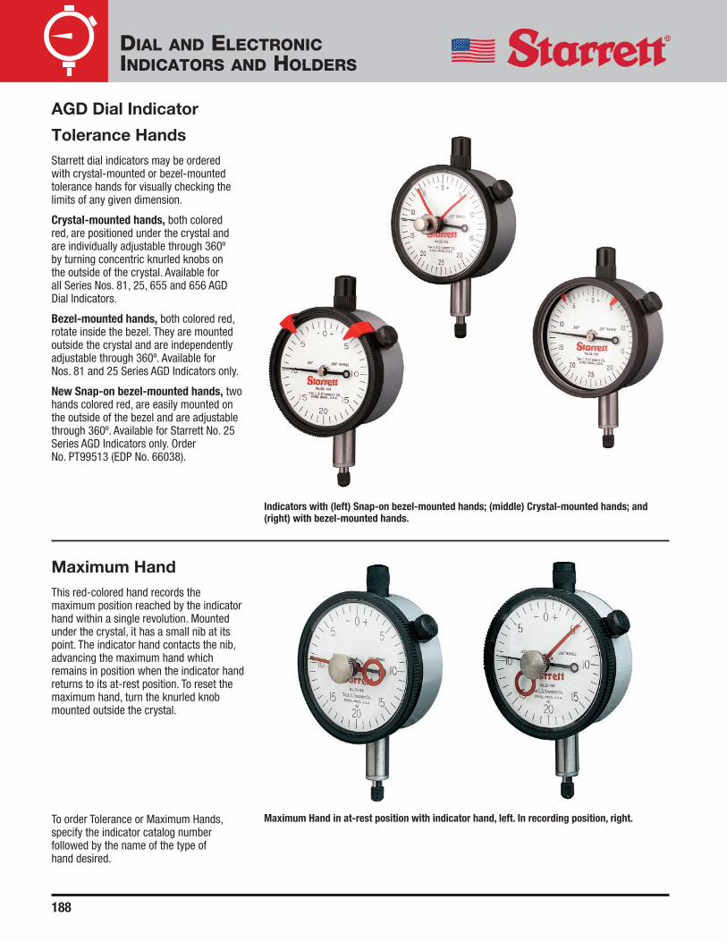
188
AGD Dial Indicator
Tolerance HandsStarrett dial indicators may be ordered with crystal-mounted or bezel-mountedtolerance hands for visually checking thelimits of any given dimension.
Crystal-mounted hands, both colored red, are positioned under the crystal andare individually adjustable through 360º by turning concentric knurled knobs on the outside of the crystal. Available for all Series Nos. 81, 25, 655 and 656 AGD Dial Indicators.
Bezel-mounted hands, both colored red,rotate inside the bezel. They are mountedoutside the crystal and are independentlyadjustable through 360º. Available for Nos. 81 and 25 Series AGD Indicators only.
New Snap-on bezel-mounted hands, twohands colored red, are easily mounted onthe outside of the bezel and are adjustablethrough 360º. Available for Starrett No. 25Series AGD Indicators only. Order No. PT99513 (EDP No. 66038).
Maximum HandThis red-colored hand records themaximum position reached by the indicatorhand within a single revolution. Mountedunder the crystal, it has a small nib at itspoint. The indicator hand contacts the nib,advancing the maximum hand whichremains in position when the indicator handreturns to its at-rest position. To reset themaximum hand, turn the knurled knobmounted outside the crystal.
Indicators with (left) Snap-on bezel-mounted hands; (middle) Crystal-mounted hands; and(right) with bezel-mounted hands.
Maximum Hand in at-rest position with indicator hand, left. In recording position, right.To order Tolerance or Maximum Hands,specify the indicator catalog numberfollowed by the name of the type of hand desired.
DIAL AND ELECTRONICINDICATORS AND HOLDERS

189
0-1� RangeMicrometer HeadGraduation Description Catalog No. EDP No.
.0001�Tester with carbide faced spindle,
716X 67228Indicator Mounting and Offset Attachment
0-25mm Range
0.002mmTester with carbide faced spindle,
716MX 67229Indicator Mounting and Offset Attachment
AccessoryDescription Catalog No. EDP No.
Indicator Mounting Attachment Only PT26009 65102
Indicator TestersNo. 716 0-1�
No. 716M 0-25mm
With direct reading capability to .0001� or0.002mm, these gages provide a rapidmeans for calibrating both AGD and dialtest indicators for linearity and repeatabilitythrough ranges up to 1� or 25mm. Thistester design is unlike others because itcan be swung to any position betweenvertical and horizontal by loosening a largehand knob which fastens the gageassembly to the base.
In addition, the micrometer head can beturned on its axis and its scale positioned tosuit the operator’s convenience byloosening a single set screw. Tensionedlocking screws prevent tipping of both thegage assembly and the indicator holdingclamp during set-up and adjustment.
The micrometer head is our No. 469 Seriessuper-precision head with reverse readingcapability. When testing a Series No. 2600or No. 2700 Electronic Indicator, a .000050�graduated head is advisable, available onspecial order.
An indicator mounting attachment holdsdovetail mount indicators, AGD indicatorswith 3/8� (9.5mm) stems and indicatorswith a holder that has a 3/16� (4.7mm)shank. Unit also has a fine adjustment tozero the indicator.
NOTE: Also available on special order withresolution to .000050� or 0.001mm.
Packed one in a box.
Dial test indicator is held in place by anoffset attachment.
No. 716.
Checking AGD dial indicator.
DIAL AND ELECTRONICINDICATORS AND HOLDERS

190
No. 2600 Full-Function IndicatorAction Features◆ Bezel rotates the reading for convenient
positioning◆ Instant inch/mm conversion◆ Zero at any position◆ Ability to retain and return reading to the
original zero reference (zero absolute[ABS])
◆ Plus/minus control to indicate direction◆ Min/Max/TIR – Min/max mode is used to
retain the lowest and highest readingsin a group, and TIR gives the differencebetween them
◆ Limits mode to enter low and high limitsfor tolerance control. This is easily doneby the shift control to enter the properfunction
◆ Preset is used to install any reading atany point in the display and is also donewith the shift control
◆ ON/OFF control with automatic off afterone hour of nonuse. (Zero referenceswill not be lost from memory)
◆ Output jack allows data transmission to the following peripherals for SPCanalysis, data collection and hard copy documentation– Starrett No. 772 Series Advanced
Data Collection Systems– Starrett No. 761 Series Data Multiplexers– Works well with Starrett DataSure®
Wireless Data Collection System– Other devices that support RS232C
Electronic IndicatorsNo. 2600 Series AGD Group 2Ranges up to 1� and 25mm
This series of indicators is available in twoversions; one with basic functions and onewith full functions for complete SPCcompatibility.
Features and Benefits Common to Both Versions:◆ Conform to the dimensions of AGD size
Group 2◆ Available with either a .375� (9.5mm)
stem or an 8mm (.315�) stem. Furnishedwith .375� (9.5mm) stem unlessotherwise ordered
◆ 1� (25mm) range◆ Readout available to .0005� and
0.01mm◆ A large, right-sized, easy-to-read LCD
digital readout, surrounded by a rotatingblack bezel
◆ Furnished with lug-on-center back◆ Starrett-designed electronics
microprocessor◆ Output to Starrett SPC Plus® system
components on most models◆ Utilizes standard indicator accessories
and holding devices◆ Battery powered and portable◆ Rugged, sealed enclosure makes them
F.F.F. (factory floor friendly)
No. 2600 Basic Indicator Action Features◆ Instant inch/mm conversion◆ Zero at any position◆ Plus/minus control to indicate direction◆ ON/OFF control with automatic off after
one hour of nonuse. (Zero referenceswill not be lost from memory)
Left, No. 2600-0 basic model; right, No. 2600-8 Full-Function Indicator.
DIAL AND ELECTRONICINDICATORS AND HOLDERS

191
Electronic IndicatorsNo. 2600 Series AGD Group 2 (continued)
11/32�DIA(9)
2-1/4� DIA(57)
50º
1-1/64�(26)
3�(77)
1-3/4�(44)
2-45/64�(69)
45/64�(18)
9/32�(7)
1/4�(6)
1/4�(6)
2-5/64� (53)DIA
1-21/64�(34)
3/8�(9.5)
3/4�(19)
15/32� (12)
13/32�(10)
7/32� (5) DIA
.375� DIA(9.5)
.156� (4) DIA
Output Format4,800 BAUD, seven data bits, even parity, one stop bit, ASCII data.Transmission is exactly 16 characters followed by a carriage return and a line feed.
SpecificationsRange Resolution Accuracy
Inch mm Inch mm Inch mm
1� 25mm.001�
0.01mm ±.001� ±0.03mm.0005�
Basic ModelsResolution
Inch mm Output Catalog No. EDP No.
.001� 0.01mm No 2600-7 66041
.0005� 0.01mm No 2600-0 65593
.0005� 0.01mm Yes 2600-1 64886
Full Function Models.001� 0.01mm Yes 2600-8 66042
.0005� 0.01mm Yes 2600-4 64889
Accessories and CablesDescription Part No. EDP No.
Adaptor from No. PT22938 Cable to PC (RS232C) PT61768 66454
Shielded Cable to Starrett No. 761 Data Multiplexer and No. 772 PT22938 64059Series Data Collector Modules and No. PT61768 Adaptor
Spindle Lifting Cable PT26263 66043
One 3-Volt Battery No. CR2450 PT61120 65446
DIAL AND ELECTRONICINDICATORS AND HOLDERS

192
WISDOM® ElectronicIndicatorsNo. 2700 SeriesAGD Groups 2, 3 andRectangularRanges up to 4� and 100mm
This is our most versatile line of electronicindicators, available in three styles, inaddition to a remote display andaccompanying probe series.
All indicators feature a glass scale designwith an unsurpassed accuracy of ± tworesolutions when measuring from a knownstandard. All have rugged, sealedenclosures as well.
American designed and manufactured.
WISDOM Basic Series◆ User Selectable Resolutions:
All available resolutions can be utilizedin the same indicator, provided they arecoarser than the resolution of thepurchased model.Example: selecting an indicator with the finest .00005�/0.00mm baseresolution means you have all eightremaining resolutions “below” thiswhich are usable in that model. If youselect an indicator with a .001�/0.02mmbase resolution, it will be your onlyavailable resolution for that model.
◆ 10 resolutions and 5 measuring rangesavailable (see specifications)
◆ Instant inch/mm conversion◆ Plus or minus travel direction◆ Maximum Reading Hold◆ Zero the tool at any position of the spindle◆ Rotating bezel◆ Auto Off: After 10 minutes of nonuse.
When Auto Off is engaged, an hourglass figure appears at the left side of the display
◆ Serial number: Indicators are furnishedwith individual serial number labels,coded with date for traceability
◆ Three power sources – operate bybattery, A/C adaptor or through data port
◆ The output jack allows datatransmission, either through a traditional wire or by connecting to aStarrett DataSure® Wireless DataCollection System end node
◆ Output data can be used by a variety ofperipherals for analysis, data collectionand hard copy documentation, including:◆ Starrett No. 772 Series Advanced
Data Collection Systems◆ Starrett No. 761 Series Data
Multiplexers◆ Other devices that support RS232C
WISDOM Plus SeriesThese models have all the features andfunctions of the Basic Series, plus thefollowing:◆ Preset mode to install any reading at any
point in the display. Reading is retainedeven if the indicator is turned off
◆ T.I.R.: Displays the difference betweenthe highest and lowest values reached
◆ Tolerancing: Permits the entering of highand low tolerances. When tolerances areexceeded, the display will flash.Numbers are retained even if theindicator is turned off
◆ Minimum reading hold◆ Hold button to freeze display: Displays
and holds the reading after themeasurement has been taken
◆ Feature lock: Unique feature locks userselections so that a wrong button pushwill not change your settings
WISDOM-OEM Indicators:Starrett can customize WISDOM models tomeet your needs. Any combination offeatures found in WISDOM Basic or PlusSeries can be furnished. In addition, unitscan be designed with features such as:◆ Special measuring ratios like 2:1, 4:1, etc.◆ Other units of measurement (cm, lb., etc.)◆ Custom LCDs, graphics◆ Varying the auto-off after nonuse time
(Example: 45 minutes vs. 10 minutes)
See specifications, next two pages.
Above: regular and oversized models.
DIAL AND ELECTRONICINDICATORS AND HOLDERS
Left, No. F2730-0; right, No. 2720-4.
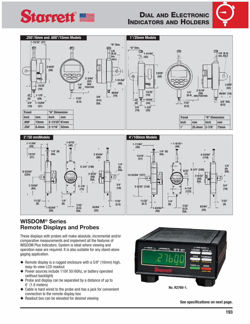
193
WISDOM® SeriesRemote Displays and ProbesThese displays with probes will make absolute, incremental and/orcomparative measurements and implement all the features ofWISDOM Plus Indicators. System is ideal where viewing andoperation ease are required. It is also suitable for any stand-alonegaging application.
◆ Remote display is a rugged enclosure with a 5/8� (16mm) high,easy-to-view LCD readout
◆ Power sources include 110V 50/60hz, or battery operated(without backlight)
◆ Probe and display can be separated by a distance of up to 6� (1.8 meters)
◆ Cable is hard wired to the probe and has a jack for convenientconnection to the remote display box
◆ Readout box can be elevated for desired viewing
.250�/6mm and .600�/15mm Models 1�/25mm Models
2�/50 mmModels 4�/100mm Models
1-15/32� (37)
1-41/64� (42)
2-9/32�(58)
2 9/32�(58)
1/4�(6.4) DIA.HOLE
1/4� (6.4)DIA. HOLE
1-1/8�(29)
1-13/64�(31)
.23�(6) .23�
(6) 3/4�(19)
3/4�(19)
7/32�(6)
63/64�(25)
3/4�(19)
1-3/8�(35)
1-19/64�(33)
13/32�(10)
13/32�(10)
1/4�(6)
1/4�(6.4)
49/64�(19)
49/64� (19)
2.058�(52)
1-51/64�(46)
2-3/64�(52)MIN.
POSITION2-5/16�
(59) MIN.POSITION
7/32�(5.5) 7/32�
(5.5)
3/8�(9.5)DIA.
1/4�(6)DIA.
2-9/32�(58)DIA.
2-9/32�(58)DIA.
7/32� (5.5)DIA.
7/32� (5.5)DIA.
1/4� (6)DIA.
1-63/64�(50)
11/32�(8.7)
13/16�(21)
1-11/64�(30)
1-9/16�(40)
1/4� (6)DIA.
8-53/64�(224)
13/16�(21)
1-11/64�(29)
5-3/4� (146)9-3/4� (248)
4-43/64�(119)
2-7/8�(73)
1/4�(6)
1/4�(6)
4-7/8�(123)
1-9/16�(40)
3/8� DIA.(9.5)
Travel “A” Dimension
Inch mm Inch mm
.600� 15mm 2-13/32� 61mm
.250� 6.4mm 2-1/16� 52mm
See specifications on next page.
9/32� (7)
3 19/64�(84)
1-63/64�(50)
11/32�(8)
63/64�(25)
7/32�(5.5)
3/4�(19)
1/4�(6)DIA.
2 43/64�(68)
5-9/32� (134)
14-53/64� (377)
No. R2760-1.
“A” Dim.
Travel “A” Dimension
Inch mm Inch mm
1� 25.4mm 2-7/8� 73mm
“A” Dim.
DIAL AND ELECTRONICINDICATORS AND HOLDERS
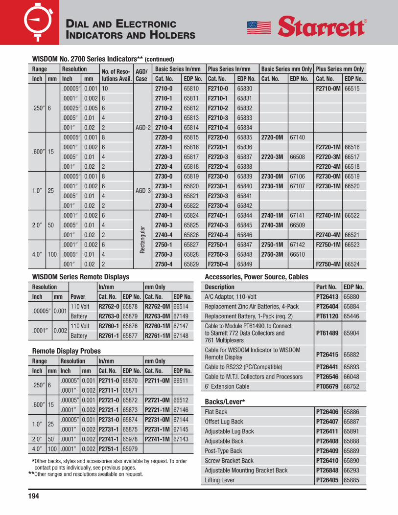
194
WISDOM No. 2700 Series Indicators** (continued)
Range Resolution No. of Reso- AGD/ Basic Series In/mm Plus Series In/mm Basic Series mm Only Plus Series mm Only
Inch mm Inch mm lutions Avail. Case Cat. No. EDP No. Cat. No. EDP No. Cat. No. EDP No. Cat. No. EDP No.
.00005� 0.001 10 2710-0 65810 F2710-0 65830 F2710-0M 66515
.0001� 0.002 8 2710-1 65811 F2710-1 65831
.250� 6 .00025� 0.005 6 2710-2 65812 F2710-2 65832
.0005� 0.01 4 2710-3 65813 F2710-3 65833
.001� 0.02 2 AGD-2 2710-4 65814 F2710-4 65834
.00005� 0.001 8 2720-0 65815 F2720-0 65835 2720-0M 67140
.600� 15 .0001� 0.002 6 2720-1 65816 F2720-1 65836 F2720-1M 66516
.0005� 0.01 4 2720-3 65817 F2720-3 65837 2720-3M 66508 F2720-3M 66517
.001� 0.02 2 2720-4 65818 F2720-4 65838 F2720-4M 66518
.00005� 0.001 8 2730-0 65819 F2730-0 65839 2730-0M 67106 F2730-0M 66519
1.0� 25 .0001� 0.002 6
AGD-32730-1 65820 F2730-1 65840 2730-1M 67107 F2730-1M 66520
.0005� 0.01 4 2730-3 65821 F2730-3 65841
.001� 0.02 2 2730-4 65822 F2730-4 65842
.0001� 0.002 6 2740-1 65824 F2740-1 65844 2740-1M 67141 F2740-1M 66522
2.0� 50 .0005� 0.01 4 2740-3 65825 F2740-3 65845 2740-3M 66509
.001� 0.02 2 2740-4 65826 F2740-4 65846 F2740-4M 66521
.0001� 0.002 6 2750-1 65827 F2750-1 65847 2750-1M 67142 F2750-1M 66523
4.0� 100 .0005� 0.01 4 2750-3 65828 F2750-3 65848 2750-3M 66510
.001� 0.02 2 2750-4 65829 F2750-4 65849 F2750-4M 66524
WISDOM Series Remote DisplaysResolution In/mm mm Only
Inch mm Power Cat. No. EDP No. Cat. No. EDP No.
.00005� 0.001110 Volt R2762-0 65878 R2762-0M 66514
Battery R2763-0 65879 R2763-0M 67149
.0001� 0.002110 Volt R2760-1 65876 R2760-1M 67147
Battery R2761-1 65877 R2761-1M 67148
Remote Display ProbesRange Resolution In/mm mm Only
Inch mm Inch mm Cat. No. EDP No. Cat. No. EDP No.
.250� 6.00005� 0.001 P2711-0 65870 P2711-0M 66511
.0001� 0.002 P2711-1 65871
.600� 15.00005� 0.001 P2721-0 65872 P2721-0M 66512
.0001� 0.002 P2721-1 65873 P2721-1M 67146
1.0� 25.00005� 0.001 P2731-0 65874 P2731-0M 67144
.0001� 0.002 P2731-1 65875 P2731-1M 67145
2.0� 50 .0001� 0.002 P2741-1 65978 P2741-1M 67143
4.0� 100 .0001� 0.002 P2751-1 65979
Accessories, Power Source, Cables Description Part No. EDP No.
A/C Adaptor, 110-Volt PT26413 65880
Replacement Zinc Air Batteries, 4-Pack PT26404 65884
Replacement Battery, 1-Pack (req. 2) PT61120 65446
Cable to Module PT61490, to Connect to Starrett 772 Data Collectors and PT61489 65904761 Multiplexers
Cable for WISDOM Indicator to WISDOM PT26415Remote Display 65882
Cable to RS232 (PC/Compatible) PT26441 65893
Cable to M.T.I. Collectors and Processors PT26546 66048
6' Extension Cable PT05679 68752
Backs/Lever*Flat Back PT26406 65886
Offset Lug Back PT26407 65887
Adjustable Lug Back PT26411 65891
Adjustable Back PT26408 65888
Post-Type Back PT26409 65889
Screw Bracket Back PT26410 65890
Adjustable Mounting Bracket Back PT26848 66293
Lifting Lever PT26405 65885
*Other backs, styles and accessories also available by request. To ordercontact points individually, see previous pages.
**Other ranges and resolutions available on request.
Rect
angu
lar
DIAL AND ELECTRONICINDICATORS AND HOLDERS

195
Electronic IndicatorsNo. 3600 SeriesAGD Group 2Ranges up to .500� and 12.7mm
No. 3600 Series Electronic Indicators havesimple, powerful, easy-to-use functions, allat an attractive price. Versions are availablefor inch/metric and metric only.
Features◆ Large, easy-to-read LCD◆ AGD group 2 size◆ Range: .500" or 12.7mm ◆ Resolution: .0005" or .01mm◆ Power On / Off button◆ Reverse travel (± control indicates
direction)◆ Zero setting at any position◆ Long battery life ◆ 3/8" diameter stem for inch/mm model
(8mm on metric-only model)◆ 4-48 spindle thread on inch/mm model
(M2.5 X .45 thread on metric-onlymodel)
◆ Lug-on-center back + additional flatback
◆ Dust cap◆ Plastic storage case with clear cover
Inch/mm Range Resolution
Inch mm Inch mm Catalog No. EDP No.
.500 12.7 .0005 0.01 3600-5 68813
Metric-Only 12.7 0.01 3600M-5 68918
AccessoryDescription Catalog No. EDP No.
SR44 Battery PT61918 67169
DIAL AND ELECTRONICINDICATORS AND HOLDERS

196
Starrett offers a full line of indicator holdersand stands to meet the requirements of awide variety of applications.
Four of these are applicable to Dial andElectronic Indicator applications, and arealso used with Test Indicators.
These models are detailed in the TestIndicator Section. Please refer to theappropriate page number for informationabout these models.
DIAL AND ELECTRONICINDICATORS AND HOLDERS
Magnetic Base Indicator Holders
No. 657AASee Page 154
No. 657TSee Page 156
No. 657-1 & 657-2See Page 157
No.660See Page 158
No. 657 SeriesBase has three precision ground, magneticcontact surfaces. Grips horizontally,vertically or upside down. V-step holds baseto round surfaces. Extra #1/4-20 tappedhole in one side of base (not shown) formounting post.
Available with or without Starrett AGD DialIndicators: inch reading No. 25-131J(graduation .0005�, dial reading 0-25-0, range .125�) or millimeter readingNo. 25-181J (graduation 0.01mm, dialreading 0-50-0, range 2.5mm). Otherindicators can be furnished on request.
A. No. 657P Magnetic Base – 1-15/16� x 1-5/8� x 1-7/8�(50 x 40 x 48mm) deep. Push button on/off switch for one-hand operation.
B. No. 657G Upright Base Post – 3/8� (9.5mm) diameter x 7-7/16� (190mm)length overall.
C. No. 657H Swivel Post Snug – Allows universal indicator adjustment – up-and-down, any vertical angle, for acomplete 360º. Two 3/8� (9.5mm) holes.
D. No. PT06784-A Gage Holding Rod – 3/8� x 9-1/2� (9.5 x 240mm) with clampingmechanism for gripping the indicator lugback (see photo below).
E. and F. Nos. 57S and 58S UniversalSnugs – Adapt various scribers andindicator shanks to rods and posts.
Base Holder Assembly and Individual ComponentsPhoto Key Description Catalog No. EDP No.
Magnetic Base, Upright Post Assembly Including 657D 52749Post, Swivel Post Snug and Gage Holding Rod
A Magnetic Base Only 657P 52757
B Upright Base Post Only 657G 52753
C Swivel Post Snug Only 657H 52785
D Gage Holding Rod with Clamp Mechanism PT06784-A 52755
E Universal Snug with 5/16� and 3/8� Hole Dia. 57S 50296
F Universal Snug with 1/4�, 5/16� and 3/8� Hole Dia. 58S 56613
Sets Including Magnetic Base, Upright Post Assembly and AGD Dial Indicatorsw/Finished Wood Case Without Case
Description Catalog No. EDP No. Catalog No. EDP No.
Base and Upright Post Assembly with Inch Reading Indicator No. 25-131J
657EZ 52751 657E 52750
Base and Upright Post Assembly with Millimeter Reading Indicator 657MEZ 56358 657ME 56357No. 25-181J
A
D
B
C
No. 657D.
E
F
Clamp mechanism grips indicator lug back.
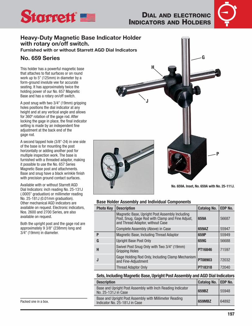
197
This holder has a powerful magnetic basethat attaches to flat surfaces or on roundwork up to 5� (125mm) in diameter by aform-ground involute vee for accurateseating. It has approximately twice theholding power of our No. 657 MagneticBase and has a rotary on/off switch.
A post snug with two 3/4� (19mm) grippingholes positions the dial indicator at anyheight and at any vertical angle and allowsfor 360º rotation of the gage rod. Afterlocking the gage in place, the final indicatorsetting is made by an independent fineadjustment at the back end of the gage rod.
A second tapped hole (3/8�-24) in one sideof the base is for mounting the posthorizontally or adding another post formultiple inspection work. The base isfurnished with a threaded adaptor, makingit possible to use the No. 657 SeriesMagnetic Base post and attachments.Base and snug have a black wrinkle finishwith precision ground contact surfaces.
Available with or without Starrett AGD Dial Indicators: inch reading No. 25-131J(.0005� graduation) or millimeter readingNo. 25-181J (0.01mm graduation).Other mechanical AGD indicators areavailable on request. Electronic indicators,Nos. 2600 and 2700 Series, are alsoavailable on request.
Both the upright post and the gage rod areapproximately 9 3/8� (238mm) long and3/4� (19mm) in diameter.
Base Holder Assembly and Individual ComponentsPhoto Key Description Catalog No. EDP No.
Magnetic Base, Upright Post Assembly Including Post, Snug, Gage Rod with Clamp and Fine Adjust, 659A 56687and Thread Adaptor, without Case
Complete Assembly (Above) in Case 659AZ 55947
P Magnetic Base, Including Thread Adaptor 659P 55949
G Upright Base Post Only 659G 56688
HSwivel Post Snug Only with Two 3/4� (19mm)
PT16846 71597Gripping Holes
JGage Holding Rod Only, Including Clamp Mechanism
PT08903 72032and Fine-Adjustment
Thread Adaptor Only PT18318 72040
Sets, Including Magnetic Base, Upright Post Assembly and AGD Dial IndicatorsDescription Catalog No. EDP No.Base and Upright Post Assembly with Inch Reading Indicator
659BZ 55948No. 25-131J in Case
Base and Upright Post Assembly with Millimeter Reading 659MBZ 64892Indicator No. 25-181J in CasePacked one in a box.
No. 659A. Inset, No. 659A with No. 25-111J.
P
G
H
J
DIAL AND ELECTRONICINDICATORS AND HOLDERS
Heavy-Duty Magnetic Base Indicator Holderwith rotary on/off switch. Furnished with or without Starrett AGD Dial Indicators
No. 659 Series

198
Inspection Holder andStarrett AGD DialIndicatorsNo. 665 SeriesThis is the most versatile dial indicatorholder with an extremely stable base (A)that is 8-1/2� (215mm) long x 2-1/4�(57mm) wide at the bottom. It can inspectworkpieces on the top surface of theground base or within a working areadefined by the 8� (200mm) upright basepost (B) and the 9-1/2� (238mm) longgage-holding rod (C). The base post can beconveniently located anywhere along the 8-1/2� (215mm) T-slot in the base.
This tool can be held in a vise or by a boltin a machine T-slot coming up through oneof the two 3/8� (9.5mm) holes in the baseand fastening down on the top surface.
A great variety of mechanical AGDindicators and electronic indicators, Nos.2600 and 2700 Series, are available onrequest.
D. Swivel Post Snug No. 665D Snug has a .375� (9.5mm) hole for thegage holding rod and a .465� (11.8mm)hole for the upright post. Also comes withthe No. 665L Reducing Bushing that canreduce the .465� (11.8mm) hole to 3/8� (9.5mm).
E. Base Reference Guide No. 665E(Optional) – Guide is used to check partsor surfaces from straight or angularsurfaces by use of the radiused guide stop. This fits into the T-slot in the bottomof the base and is fastened at right angles to the length.
Push up to a radius surface or slide along aradius surface.
F. Square Keyway Guide No. 665F(Optional) – This guide can also bereferenced from a square edge, a T-slot ora keyway with at least a 1/2� (12.7mm)width. Has square edges and is fastened at right angles to the length.
Push up to a square edge or slide along asquare edge.
No. 665JZ with No. 25-131J Indicator.
(Continued on next page.)
E
F
A
B
C
D
DIAL AND ELECTRONICINDICATORS AND HOLDERS

199
No. 665 Series (continued)
There are three very useful inspectioncombinations that can be made byremoving the complete swivel post snugand gage holding rod and using them as follows:
G. Clamp No. 665G Take the clamp and put the clamp post intothe snug and lock it. Now this combinationcan be used to clamp the gage holding rodand the indicator into hard-to-reach placesfor inspecting jigs, fixtures, lining up workon centers and machine tables.
The clamp has a 3� (75mm) capacity and a post with an approximately 5-3/4�(145mm) length. The clamp post is .464�(11.8mm) diameter that fits into the regularswivel post snug No. 665D.
There are three other clamp post diameteroptions available – No. 665G-3/8 is a 3/8�(9.5mm) diameter clamp post that can beused in the regular swivel post snug No.665D with the addition of the No. 665Lreducing bushing. The Nos. 665G-5/16 (7.9mm) and 665G-1/4 (6.3mm) can beused with other snugs to hold an indicator.
H. Tool Post Holder No. 665H Put one end of the offset arm into theswivel post snug No. 665D (with the No. 665L reducing bushing in it). Then putthis rectangular tool post holder No. 665Honto the other arm. This combination nowallows for a good, tight setup in lathe toolposts and other machine setups.
I. Offset Arm No. 665G-1 Another very popular measuringcombination is to put the reducing bushing(which is furnished) into the snug and thenput one leg of the offset arm into it. Nowthe tool can be used in a 3/8� (9.5mm)chuck or collet to sweep a large area.
J. Reducing Bushing No. 665L Bushing has a .465� (11.8mm) O.D. and a .375� (9.5mm) I.D.
Individual ComponentsKey Description Catalog No. EDP No.
A* Base Only 665A 52783
B* Upright Base Post .464� x 8� (11.8 x 200mm)665B 52784with Clamp Mechanism
C* Gage Holding Rod 3/8� x 9-1/2� (9.5 x 240mm)PT06784-A 52755with Clamp Mechanism
D* Swivel Post Snug with .465� and 3/8� (11.8 and 9.5mm)665D 52754holes with No. 665L Reducing Bushing
E Base Reference Guide 665E 52787
F Square Keyway Guide 665F 52788
G* Clamp with .464� x 5-3/4� (11.8 x 146mm) Post 665G 52792
Clamp with 1/4� (6.3mm) Diameter Post 665G-1/4 52793
Clamp with 5/16� (7.9mm) Diameter Post 665G-5/16 52794
Clamp with 3/8� (9.5mm) Diameter Post 665G-3/8 52795
H* Tool Post Holder Approximately 1� x 7/16� (25 x 11mm) 665H 52790
I* Offset Arm 3/8� (9.5mm) Diameter 3� and 5 1/2�665G-1 52789(75 and 140mm) Arms
J* Reducing Bushing Only (for Swivel Post Snug) 665L 52756.465� (11.8mm) O.D. .375� (9.5mm) I.D.
Inspection Sets with AGD Dial IndicatorsDescription Catalog No. EDP No.
Complete with Components * and No. 25-131J Inch Reading Indicator in Case
665JZ 56275
Complete with Components * and No. 25-181J Millimeter Reading Indicator in Case
665MJZ 56276
Packed one in a box.
H
I
J
G
DIAL AND ELECTRONICINDICATORS AND HOLDERS

200
Dial Comparators with granite baseNo. 675GJ No. 675GMJ Extremely rugged and universallyadjustable to any position, these gages are well suited for inspection, layout,checking and lineup operations anywherein the shop. All settings are individuallymade without disturbing others.
These versatile stands allow the indicatorto be positioned at any height within thecapacity of the upright base post – 360ºboth horizontally and vertically.
The indicator can also be movedlengthwise within the capacity of the 3/4� x 9-7/8� (19 x 250mm) horizontalgage-holding rod.
A special feature of this tool is thesensitive, fine-adjustment at the end of thegage rod. The fine-adjustment range isapproximately 1/4� (6.3mm).
A 1/4� (6.3mm) steel indicator contact pointis provided, but contact points in otherlengths and materials are also available –see previous accessory pages.
This holder has a Starrett Grade-A CrystalPink Granite base that is 8� x 12� x 2�(200 x 300 x 50mm), and is finished to anoverall tolerance of .0001� (0.0025mm).
No. 675G with No. F2710-1 Electronic Indicator.
Complete UnitsDial Indicator Specifications* With Granite BaseGraduation Dial Reading Range Indicator No. Catalog No. EDP No.
.0005� 0-25-0 .125� 25-131J 675GJ 55964
0.01mm 0-50-0 2.5mm 25-181J 675GMJ 56129
Individual ComponentsDescription Catalog No. EDP No.
Granite Base, Upright Base Post and Gage Holding Rod, Including Clamp Mechanism and Fine-Adjustment
675G 66051
Gage Holding Rod Only, Including Clamp Mechanism PT08903 72032and Fine-Adjustment
Swivel Post Snug Only with Two 3/4� (19mm) Gripping Holes PT16846 71597
NOTE: Available with special nonshock mechanism or without indicator.Any Starrett AGD Dial or Electronic Indicator can be interchanged with indicators listed. Pleasespecify when ordering.
*For complete specifications see previous pages.
DIAL AND ELECTRONICINDICATORS AND HOLDERS

201
These bench-type comparator gages are ruggedly built for in-process and final inspection work.
The dial indicator can be adjusted vertically and locked in anyposition. A sliding ring with locking screw below the beam permitsswinging the indicator to either side. The ring also acts as a safetydevice, preventing the beam from accidentally dropping. There is afine adjustment on the beam for final indicator setting.
The hand lifting lever on the indicator raises the spindle andreleases it to contact the work. A left hand lever is furnished unlessspecified otherwise.
Both gages have a maximum vertical capacity of 9-1/4� (235mm)and a throat depth of 5� (125mm) and a vertical indicator fineadjustment of up to 1/2� (12.7mm). Post diameter is 1-1/2�.
No. 653 Series have a ribbed, precision ground cast iron basemeasuring approximately 8� x 9� (200 x 225mm).
No. 653G Series have a Starrett Grade A, Crystal Pink Granite base,measuring 8� x 12� x 2� (200 x 300 x 50mm). Base is finished to anoverall tolerance of .0001� (0.0025mm).
No. 653J. No. 653GJ.
Dial ComparatorsNo. 653 Series with cast iron base, inch and mm readingNo. 653G Series with granite base, inch and mm reading
Complete UnitsDial Indicator Specifications* With Cast Iron Base With Granite Base
Graduation Dial Reading Range Indicator No. Catalog No. EDP No. Catalog No. EDP No.
.001�0-50-0
.250� 655-141J 653J 52737 653GJ 55966
0.01mm 2.5mm 655-181J 653MJ 56146 653GMJ 56127
Individual ComponentsDescription Catalog No. EDP No.
Comparator with Cast Iron Base, without Indicator 653 55917
Comparator with Granite Base, without Indicator 653G 56646
NOTE: Available with special nonshock mechanism or without indicator.Any Starrett AGD Dial or Electronic Indicator can be interchanged with indicators listed.Please specify accordingly.
*For complete specifications see previous pages.
DIAL AND ELECTRONICINDICATORS AND HOLDERS

202
Dial Bench GagesNo. 652 Series with sliding table and fine-adjustment
These compact gages are used for benchor beside-the-machine inspection of smallparts and materials. The hand lever ispressed down to lift the spindle andreleased to contact the work under uniformpressure. Gages are furnished with lefthand lever unless specified otherwise. Thedial can be rotated for zero setting andlocated in place with the bezel clamp.
The 652 has a ground and lapped table thatcan be adjusted vertically and locked inposition. A sliding ring below a tablebracket can also be locked in positionpermitting the table to swing to either side. Final setting of the table is made by a fine-adjusting screw.
Size Specifications Inch mm
Maximum Vertical Capacity 1-3/4� 44mm
Maximum Throat Depth 1-5/8� 40mm
Table Diameter 2� 50mm
Table Fine-Adjustment 1/8� 3mm
Base Diameter 5� 125mm
Dial Indicator Specifications*Graduation Dial Reading Range Indicator No. Catalog No. EDP No.
.0005� 0-25-0 .125� 25-131J 652JZ 52733
0.01mm 0-50-0 2.5mm 25-181J 652MJZ 52734
*For complete specifications see previous pages.
Furnished in case. Packed one in a box.
NOTE: All gages can be furnished with tolerance hands; special nonshock mechanism;special sizes and shapes of contact points and tables. Available by request.
No. 652JZ.
DIAL AND ELECTRONICINDICATORS AND HOLDERS

J.W. DONCHIN CO. 4841-43 W. Chicago Ave. • Chicago, IL 60651-3224Ph: 773-261-2182 • Fax: 773-261-2867 • [email protected] • www.jwdonchin,com
Special Function Indicator Gages
203 Chamfer Gages Series Nos. 683, 684, 685, 686
204 Chamfer Gages Series Nos. 683, 684, 685, 686
205 Countersink Gages Series No. 687, 688, 689
206 Hole Gages Series No. 690, 690M
207 Dial Sheet Gages Series No. 170, 170M
Dial Indicator Pocket Gages Series No. 1010, 1010M
208 Portable Dial Thickness Gages Series No. 1015, 1015M
209 Dial Indicator Snap Gages Series No. 1150
210 Dial Indicator Groove Gages Series No. 1175, 1175M
211 Dial Caliper Gages Series No. 1017, 1018
Internal Dial Caliper Gages Series No. 1019, 1019M
212 Dial Out-Of-Roundness Gages Series No. 681, 681M
213 Shaft Alignment Clamp Sets Series No. 668
214 Crankshaft Distortion Dial/Strain Gage Series No. 696, 696M
215 Crankshaft Distortion Dial/Strain Gage Series No. 696, 696M
216 Automotive Disc Brake Indicating Gages Series No. 1016, 1016M
217 Cylinder Gages Series No. 452, 452M
218 Dial Indicator Diameter Gages Series No. 1102, 1102M
219 Dial Indicator Diameter Gages Series No. 1102, 1102M
220 Dial Indicator Diameter Gages Series No. 1101, 1101M
221 Heavy-Duty Dial Indicator Diameter Gages Series No. 1100, 1100M
222 Internal-External Adjustable Setting Master for
Starrett No. 1102 Diameter Gages Series No. 1102, 1127
223 Internal-External Adjustable Setting Masters for
Starrett Nos. 1100 and 1101 Series Diameter Gages Series No. 1126
224 Dial Depth Gages Series No. 640, 643, 644
Top Reading Dial Depth Gages Series No. 642, 642M

203
Special Function Dial GagesThis section includes special function dial gages that we list as regular items. Gages are also available with electronic indicators onrequest, where noted.
In addition, we have made many other special function gages to suit a wide variety of our customers’ specific requirements. If you havea special application, we invite you to submit your drawings and specifications to our Special Order Department at 121 Crescent Street,Athol, MA 01331, USA . We will be happy to provide a prompt quotation.
◆ Groove Gages◆ Caliper Gages◆ Depth Gages◆ Out-of-roundness Gages◆ Inside Dial Gages
◆ Automotive Gages◆ Crankshaft Distortion Gages◆ Cylinder Gages◆ Disc Brake Gages◆ Large Diameter Gages
◆ Chamfer Gages◆ Countersink Gages◆ Hole Gages◆ Bore Gages – See Bore Gages Section◆ Direct-Reading Thickness Gages◆ Snap Gages
Chamfer Gages
For Internal Chamfers:No. 683 Series 0-90ºNo. 684 Series 90-127º
For External Chamfers:No. 685 Series 0-90º No. 686 Series 90-127º These gages directly measure the diameter ofchamfered holes. No setting master isnecessary.When the three-blade plunger ispressed against a flat surface, the gage shouldread the set number stamped on the back ofthe indicator. In case of wear, the gage may beadjusted to read the proper number.
All ground surfaces are of hardened tool steel. Indicators are AGD design.
Internal gages will measure the largestdiameter of any chamfer that has anincluded angle within the range of anglesprinted on the dial face of the gage.
External gages will measure the smallestdiameter of any chamfer within the range ofangles printed on the dial face of the gage.
See specifications on next page.
Right: No. 684-2Z ChamferGage with No. F2710-3Electronic Indicator on theNo. 695 Check Stand.
SPECIAL FUNCTIONINDICATOR GAGES
Left, No. 683-1Z;
Right, No. 685-3Z.

204
Inch Reading0-90º Angle 90-127º Angle
Range Catalog No. EDP No. Catalog No. EDP No.
0-3/8� 683-1Z 63684 684-1Z 63688
0-1/2� 683-2Z 63685 684-2Z 63689
0-1� 683-3Z 63686 684-3Z 63690
1-2� 683-4Z 63687 684-4Z 63691
Millimeter Reading with Yellow Dials0-9.5mm 683M-1Z 64989 684M-1Z 64993
0-12.7mm 683M-2Z 64990 684M-2Z 64994
0-25mm 683M-3Z 64991 684M-3Z 64995
25-50mm 683M-4Z 64992 684M-4Z 64996
Inch Reading1/8-1/2� 685-1Z 63692 686-1Z 63695
3/16-1� 685-2Z 63693 686-2Z 63696
1-2� 685-3Z 63694 686-3Z 63697
Millimeter Reading with Yellow Dials3.2-12.7mm 685M-1Z 64997 686M-1Z 65000
4.7-25mm 685M-2Z 64998 686M-2Z 65001
25-50mm 685M-3Z 64999 686M-3Z 65002
No. 683(Internal)
No. 684(Internal)
No. 686(External)
0-90º
0-90º
90-127º
No. 685(External)
Diameter
Diameter Diameter
Diameter
Check Gage Stand for Chamfer, Countersink and Hole GagesDescription Catalog No. EDP No.
8-3/16� H x 6� W x 4� D (212 x 150 x 100mm)Hold Downs – 5� (125mm) on Center – 695 638751/4� (6.3mm) Holes
Chamfer Gages (continued)
Internal Gages
External Gages
NOTE: Also available with electronic indicators.Please specify.
Gages furnished in deluxe padded case.
90-127º
SPECIAL FUNCTIONINDICATOR GAGES

205
Countersink GagesNo. 687 Series 82ºNo. 688 Series 90ºNo. 689 Series 100ºStarrett Countersink Gages are offered inthree different angles so that the gage setson the angular side of the countersink, asopposed to a chamfer gage which sets onthe top edge of the chamfer.
This gage directly reads the large diameter of the countersink in .002� or0.05 mm increments. A set master ring isfurnished with each gage for calibrationand setting. Press the button on top of theindicator to firmly depress the gage headinto the countersink. When the gage isremoved, the indicator reading is held inplace until the reset button is activated.
All ground surfaces are of hardened toolsteel. Indicators are AGD design.
82-90-100º
Diameter
Check Gage Stand for Chamfer, Countersink and Hole GagesDescription Catalog No. EDP No.
8-3/16� H x 6� W x 4� D (212 x 150 x 100mm)Hold Downs – 5� (125mm) on Center – 1/4� (6.3mm) Holes
695 63875
Inch Reading82º Angle 90º Angle 100º Angle
Range Catalog No. EDP No. Catalog No. EDP No. Catalog No. EDP No.
.020-.170� 687-1Z 63698 688-1Z 63702 689-1Z 63706
.160-.360� 687-2Z 63699 688-2Z 63703 689-2Z 63707
.360-.560� 687-3Z 63700 688-3Z 63704 689-3Z 63708
.560-.780� 687-4Z 63701 688-4Z 63705 689-4Z 63709
Millimeter Reading with Yellow Dials0.5-4.3mm 687M-1Z 65003 688M-1Z 65007 689M-1Z 65011
4-9mm 687M-2Z 65004 688M-2Z 65008 689M-2Z 65012
9-14.2mm 687M-3Z 65005 688M-3Z 65009 689M-3Z 65013
14.2-19.8mm 687M-4Z 65006 688M-4Z 65010 689M-4Z 65014
Nos. 687,688, 689
NOTE: Also available with electronic indicators.Please specify.
Gages furnished in deluxe padded case.
Left-to-right: Nos. 687-4Z, No. 688-3Z, No. 689-1Z.
SPECIAL FUNCTIONINDICATOR GAGES

206
Hole GagesNo. 690 Series .010-.330�
No. 690M Series 0.25-8.35mm
These hole gages will check hole diameters to .001� and 0.02mm. They are fast, accurate, easy to read and have a balanced design for easy one-hand operation.
The gage can be pressed down on a flat surface and checked so the size should read the same as the set numberstamped on the back of the indicator. It can also be checked and set with anoptional “setting master”.
All ground surfaces are of hardened toolsteel. Indicators are AGD design.
Holes that need to be accurately checkedmust have no chamfers or countersinks.
Inch Reading Gages Set Masters (Optional)
Range Catalog No. EDP No. Part No. EDP No.
.010-.040� 690-1Z 63710 PT23710-1 63879
.030-.130� 690-2Z 63711 PT23710-2 63880
.130-.230� 690-3Z 63712 PT23710-3 63881
.230-.330� 690-4Z 63713 PT23710-4 63882
Millimeter Reading with Yellow Dials.25-1.00mm 690M-1Z 63714 PT23710-5 63883
.75-3.30mm 690M-2Z 63715 PT23710-6 63884
3.30-5.85mm 690M-3Z 63716 PT23710-7 63885
5.85-8.35mm 690M-4Z 63717 PT23710-8 63886
No. 690
MeasureDiameter
Check Gage Stand for Chamfer, Countersink and Hole GagesDescription Catalog No. EDP No.
8-3/16� H x 6 � W x 4� D (212 x 150 x 100mm)Hold Downs – 5� (125mm) on Center – 695 638751/4� (6.3mm) Holes
NOTE: Also available with electronic indicators.Please specify.
Gages furnished in deluxe padded case.
Left, No. 690-3Z; right, No. 690M-2Z.
SPECIAL FUNCTIONINDICATOR GAGES

207
Inch ReadingRange Graduation Dial Reading Contacts Catalog No. EDP No.
.375�.001� 0-100
Flat1010Z 53114
.0005� 0-50 1010EZ 53115
.275� .001� 0-100 Round 1010RZ 56067
Millimeter Reading9mm 0.01mm 0-100 Flat 1010MZ 53116
Inch ReadingRange Graduation Dial Reading Catalog No. EDP No.
.150� .001� 0-100 170Z 50647
Millimeter Reading2.5mm 0.2mm 0-100 170MZ 66036
Dial Sheet GagesNo. 170 .150�
No. 170M 2.5mm
Measures the thickness of sheet materialslike paper, cardboard, leather, plastics andmetals. Raise the movable contact, insertthe work, remove thumb, and springpressure holds the work parallel with thecontacts. The thickness is registered on thedial. By turning the knurled bezel, the dialmay be moved to bring the hand to zero.The contact edges are radiused to preventthe work from being marred or deflected.The flat contact area measures 5/16�(8mm) in diameter. Black finish.
◆ Throat depth is 1-1/8� (28.5mm)◆ Furnished in deluxe padded case
Dial Indicator Pocket GagesNo. 1010 Series .375�
No. 1010M 9mm
Handy pocket gage is approximately thesize of a thin pocket watch. Ideal forinspectors, purchasing agents andsalespeople to check the size of materialsup to 3/8� or 9mm thick. The gage fitsnaturally into the curve between the thumband index finger. A slight pull on theserrated top plate raises the spindle.
◆ The throat depth ranges from 1/2�(12.7mm) down to 5/16� (8mm)
◆ Models are available with flat orrounded contacts as listed
◆ The diameter of both the flat or roundcontacts are 1/4� (6.3mm)
◆ The gage has a small count hand for recording each revolution of thelarge hand
◆ The case is chrome plated, and the dialis covered with an unbreakable crystal
◆ Furnished in attractive, protective case
No. 170Z.
No. 1010RZ.
Thickness GagesThree handy, specialized, direct-readinggages, as shown on these two pages.
SPECIAL FUNCTIONINDICATOR GAGES

208
Portable Dial Thickness GagesNo. 1015 Series 0-1�
No. 1015M Series 0-25mm
After inserting work between themeasuring contacts, releasing the lever willcause the spindle to contact the work,giving an accurate size reading becausemeasuring pressure is independent of theuser. Indicators have jewel bearings andcontinuous dials. (Models with balanceddials, other graduations and ranges are also available on special order. Electronicindicators can also be furnished.) Throatdepths include 2-1/2�, 4�, and 6�. Thecontact edges are radiused to prevent thework from being marred or deflected. Theflat contact area measures 1/4� (6.3mm) in diameter and is 1/8� (0.125mm) thick.Special contact sizes and shapes areavailable by request.
Inch Reading
Throat Dial Indicator Without Case Case Only
Depth Range Graduation Dial Reading Model No. Catalog No. EDP No. Catalog No. EDP No.
2-1/2�1/2� .0005� 0-50 1015A-431J 1015A 53119 1015AZZ 55407
1� .001� 0-100 1015B-441J 1015B 53121 1015BZZ 55408
4�1/2� .0005� 0-50 1015A-431J 1015A-4 67646
1� .001� 0-100 1015B-441J 1015B-4 67649
6�1/2� .0005� 0-50 1015A-431J 1015A-6 67652
1� .001� 0-100 1015B-441J 1015B-6 67655
Millimeter Reading
63mm10mm 1015MA-481J 1015MA 56131 1015AZZ 55407
25mm 1015MB-881J 1015MB 56133 1015BZZ 55408
100mm10mm 1015MA-481J 1015MA-100 67647
25mm0.01mm 0-100
1015MB-881J 1015MB-100 67650
150mm10mm 1015MA-481J 1015MA-150 67653
25mm 1015MB-881J 1015MB-150 67656
No. 1015A.
No. 1015A-6.
Packed one in a box.
SPECIAL FUNCTIONINDICATOR GAGES

209
Dial Indicator Snap GagesNo. 1150 Series 0-8�
These compact gages have rigid aluminumalloy frames protected from hand heat byinsulating handles. They are used to gageoutside diameters to an accuracy of .0001�.
Dimensional variations are transmitted to thedial indicator through a linear friction-freetransfer mechanism totally enclosed forprotection against side thrust, foreign matterand coolants. Flat gaging contacts simplifymeasurement close to shoulders. The topsensitive contact may be reversed to presenta spherical face to the work. An adjustablebackstop simplifies centering the work.
The contacts and backstop are 5/16�diameter hardened tool steel, precisionground and lapped flat. The contacts areindividually adjustable to a maximum 2� range and are locked in position bytightening parallel-lock clamps to maintainparallelism of faces. Both contacts are alsokeyed to maintain orientation of facesregardless of adjustment.
Plus or minus tolerances are read directlyfrom the indicator since the dial face has a double row of graduations reading inopposite directions from zero, with “minus”graduations in red and “plus” in black. Theindicator can be rotated 360º and locked inposition to read from any angle, and a fine-adjusting screw provides for zero settingthe hand. A guard protects the dial indicatorwhen the gage is laid down.
A bench stand is available to convert thegage to a bench comparator. The series isalso available with indicators other thanthose listed, a No. 717 Gage Amplifier andgaging head in place of the indicator,carbide faces on the contacts, special
SPECIAL FUNCTIONINDICATOR GAGES
Left: No. 1150Z-2 as a handheld snap gage.Center: No. 1150Z-2 with No. F2710-1 Electronic Indicator.Right: No. 1150Z-2 mounted on a No. 1150 Bench Stand.
Inch ReadingDial Indicator Without Stand
Range Graduation Dial Reading Range Model No. Catalog No. EDP No.
0-2� 1150Z-2 53168
2-4�.0001�
+ 10 .040� 81-111-11501150Z-4 53169
4-6� – 10 1150Z-6 53170
6-8� 1150Z-8 53171
AccessoryBench Stand Only 1150 53172
Wide Face Ball or Roll Blade Type Offset Offset for up to 9/16� Square Face Groove
Some of the many interchangeable anvil configurations designed to suit special applications.
Special Contacts
Gages furnished in case. Packed one in a box.
contact and backstop shapes and sizes,variable gaging pressure control, disc
setting and otherspecial masters, and larger ranges.

Dial Indicator GrooveGagesNo. 1175 .375-6�
No. 1175M 9.5-150mm
This lightweight gage is used for in-processor bench inspection of oil grooves, snapring retainer grooves, “O” ring seat retainergrooves and similar internal recesses. It isalso useful for checking bore dimensionsand testing for taper, bell-mouth and out-of-roundness.
The movable, sensitive gaging contact hasa 1/2� (12.7mm) retractable range andtransfers the measurement through alinear, friction-free transfer mechanism tothe dial indicator. The lower reference jawis fixed and supports the entire weight ofthe gage and the operator’s hands, thuspreventing incorrect gaging pressure andfalse readings.
The reference jaw can be mounted in twopositions on the range adjusting bar. Thebar itself is also adjustable for greater orlesser range. A fine adjustment screw and alock are also provided.
This gage has the following features:◆ Supplied with two sets of jaws, both
readily interchangeable◆ Three sets of contacts are furnished
(Styles 1-10, 2-10, 2-20) that can beattached to the ends of the jaws withoutreplacing the entire jaw. Contacts haveflush ends so that grooves at the bottomof blind holes can be gaged. Thecontacts are hardened steel with a hardchrome finish for long life
◆ Gage can be set with gage blocks orother methods such as micrometers,vernier calipers and ring gages.
Special jaws for 4� and 6� (100mm and150mm) gaging depths, a diameter rangeextension bar from 6-12� (150-300mm),dial indicators graduated in .001�, or anyspecial modification of gaging contacts andjaws, are also available by request throughour Special Order Department
SPECIAL FUNCTIONINDICATOR GAGES
Furnished with storage case. Packed onein a box.
210
No. 1175Z.
1.25� (32)MAX. GAGING DEPTH
2.50� (64)MAX. GAGING DEPTH
3.00� (76.2)GROOVE I.D.
MAX.GROOVE I.D.
LOWER JAW
PT30913
WILLENTERMIN.BORE
CONTACTMOUNTING SCREWPT03497
UPPERJAWPT30916 B
A
LOWER JAWPT30914
CONTACTMOUNTING SCREW08272-0
WILLENTER.375�(9.5)MIN.BORE
Will Enter Maximum
Contact Part No. Minimum Bore Groove I.D. A B
Set Upper Lower Inch mm Inch mm Inch mm Inch mm
Style 1-10 PT30917 PT30917 .375� 9.5 3.00� 75 .100� 2.5 .024� 0.6
Style 2-10 PT30918 PT30919 .690� 17.5 5.00� 125 .140� 3.6 .034� 0.8
Style 2-20 PT30920 PT30921 1.00� 25 6.00� 150 .265� 6.7 .051� 1.3
Dial Indicator
Range Model No. Graduation Reading Range Catalog No. EDP No.
.375-6� 81-136-1175 .0005� ±30 .060� 1175Z 53173
9.5-150mm 81-181-1175 0.01mm ±100 2.5mm 1175MZ 65032
UPPER JAWPT30915
.024�.100�(2.54)
STYLE 1-10 STYLES 2-10, 2-20
Contact Set Specifications:Style 1-10 is for the smaller jaws and can enter a .375� (9.5mm) bore. Styles 2-10 and 2-20 are used on the larger jaws to get the range up to 6� (150mm).
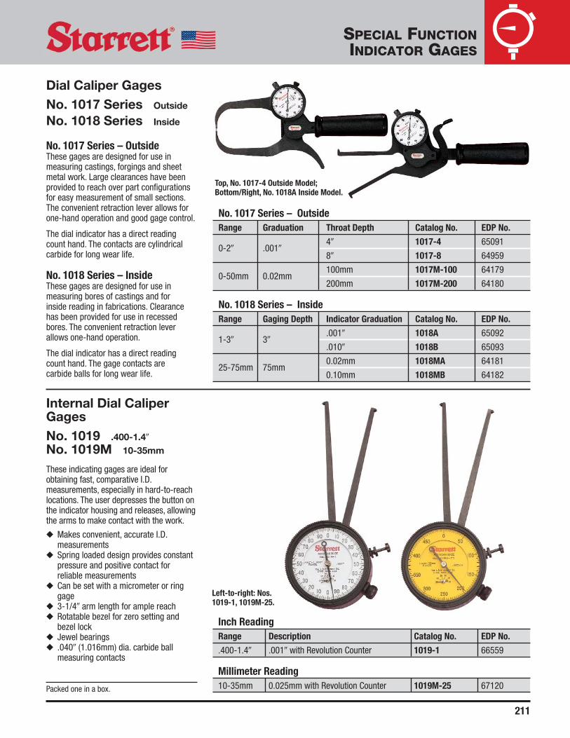
211
Internal Dial CaliperGagesNo. 1019 .400-1.4�
No. 1019M 10-35mm
These indicating gages are ideal forobtaining fast, comparative I.D.measurements, especially in hard-to-reachlocations. The user depresses the button onthe indicator housing and releases, allowingthe arms to make contact with the work.
◆ Makes convenient, accurate I.D.measurements
◆ Spring loaded design provides constantpressure and positive contact forreliable measurements
◆ Can be set with a micrometer or ringgage
◆ 3-1/4� arm length for ample reach◆ Rotatable bezel for zero setting and
bezel lock◆ Jewel bearings◆ .040� (1.016mm) dia. carbide ball
measuring contacts
Packed one in a box.
Inch ReadingRange Description Catalog No. EDP No.
.400-1.4� .001� with Revolution Counter 1019-1 66559
Millimeter Reading10-35mm 0.025mm with Revolution Counter 1019M-25 67120
Left-to-right: Nos.1019-1, 1019M-25.
SPECIAL FUNCTIONINDICATOR GAGES
Dial Caliper GagesNo. 1017 Series Outside
No. 1018 Series Inside
No. 1017 Series – OutsideThese gages are designed for use inmeasuring castings, forgings and sheetmetal work. Large clearances have beenprovided to reach over part configurationsfor easy measurement of small sections.The convenient retraction lever allows forone-hand operation and good gage control.
The dial indicator has a direct readingcount hand. The contacts are cylindricalcarbide for long wear life.
No. 1018 Series – InsideThese gages are designed for use inmeasuring bores of castings and for inside reading in fabrications. Clearancehas been provided for use in recessedbores. The convenient retraction leverallows one-hand operation.
The dial indicator has a direct readingcount hand. The gage contacts are carbide balls for long wear life.
No. 1017 Series – OutsideRange Graduation Throat Depth Catalog No. EDP No.
0-2� .001�4� 1017-4 65091
8� 1017-8 64959
0-50mm 0.02mm100mm 1017M-100 64179
200mm 1017M-200 64180
No. 1018 Series – InsideRange Gaging Depth Indicator Graduation Catalog No. EDP No.
1-3� 3�.001� 1018A 65092
.010� 1018B 65093
25-75mm 75mm0.02mm 1018MA 64181
0.10mm 1018MB 64182
Top, No. 1017-4 Outside Model;Bottom/Right, No. 1018A Inside Model.

212
Dial Out-Of-RoundnessGagesNo. 681 1-1/4–5�
No. 681M 30-125mm
A compact, easy-to-apply gage forchecking the out-of-roundness ofconnecting rod bearings and holes ofshallow depth. Also for inspectingparallelism and for alignment of slots and assembled parts in jig and fixture work. A dial indicator is mounted on top of the base, and on the bottom a positiveadjustable slide which is readily set to theapproximate hole size or slot width. Thisslide holds the stationary contact plus twocentralizing contacts under spring tension,insuring constant alignment. Bearingsurfaces and contact points are ofhardened steel. The contact points areinserted to a depth of approximately 3/8� (9.5mm).
Dial Indicator
Range Graduation Dial Reading Range Model No. Catalog No. EDP No.
1-1/4-5� .001� 0-25-0 .125� 81-145 681 52899
30-125mm 0.01mm 0-50-0 2.5mm 81-181 681M 52900
Packed one in a box.
SPECIAL FUNCTIONINDICATOR GAGES
Inside Dial GagesNo. 697 2-3/8–18�
No. 697M 61–458mm
These gages are used between two wallsto check parallelism and also to takecomparative measurements of internaldiameters. There are ten rods and oneextension furnished. The rods are markedto designate the approximate overall lengthof the gage. All measuring contacts arerounded. Tool can be set with a micrometer.
The indicator bezel is rotated to adjust thedial in relation to the hand and has a non-breakable crystal. The movement of the dialindicator is approximately 5/32� (4mm).Rods of different lengths can also befurnished on request.
Furnished in attractive, protective case. Packedone in a box.
Range Graduation Dial Reading One Revolution Catalog No. EDP No.
2-3/8–18� .001� 0-20-0 .040� 697Z 52907
61-458mm 0.02mm 0-50-0 1.0mm 697MZ 52908

213
Shaft Alignment ClampSetsNo. 668 SeriesThe Starrett Shaft Alignment Clamp isdesigned for fast, precise alignment ofmotors, pumps, compressors, etc. Thissystem is capable of addressing radial andangular misalignment problems and can beset up within minutes.
Features◆ Lightweight clamp design made of black
anodized aluminum◆ Rigid 3/8� diameter stainless steel
indicator posts provided in three lengths(5�, 7-7/16�, and 9�)
◆ Extension plate allows for added radialclearance
◆ Heavy-duty roller chain can accommodateup to a 7-1/2� diameter shaft
◆ Sets are available with either two StarrettNos. 196B5 or 81-141J Indicators
◆ Excess roller chain can be secured to theside of the chain clamp
◆ A second shaft alignment clamp can bemounted across from the first clamp to actas a vertical “target” for face alignment
Description Catalog No. EDP No.
1 each: Chain Clamp, Extension Plate, Posts (5�, 7-7/16�, 9�), S668A 67150without Case
2 each: Chain Clamp, Extension Plate, Posts (5�, 7-7/16�, 9�), S668BZ 67151with Fitted Case
2 each: Chain Clamp, No. 196B5 Indicator, PT18724 Snug, S668CZ 67152Extension Plate, Posts (5�, 7-7/16�, 9�), with Fitted Case
2 each: Chain Clamp, No. 81-141J Indicator,No. 657Y Indicator Attachment, No. PT18724 Snug, S668DZ 67153Extension Plate, Posts (5�, 7-7/16�, 9�), with Fitted Case
Photo Individual Catalog EDPKey Components No. No.
AChain Clamp
668 67155Only
BExtension Plate
PT99529 67454Screw, Washer
C 5� Post PT27981 67302
D 7-7/16� Post 657G 52753
E 9� Post PT27982 67303
F Snug Complete PT18724 50710
GIndicator
657Y 52765Attachment
No. S668CZ mounted on coupling.
No. S668DZ.
A
C
D
E
G
B
F
SPECIAL FUNCTIONINDICATOR GAGES

214
SPECIAL FUNCTIONINDICATOR GAGES
No. 696B Balancing Attachment isfurnished with the gage. For certainapplications, like turning the crank undertest with the gage in place, the attachmentcan be adjusted to maintain the face of theindicator upward or in desired position. Toinstall it on a strain gage in use, remove theknurled clamping nut, then the doweledplate or end strap at either end by thescrew. The unit is then positioned over thehubs on two sides of the indicator head. Aspring plunger provides the friction thatholds the balance in proper relation toposition. The parts are nickel plated.
The dial indicator movement isapproximately 5/32� (4mm) and with rodsand extension, provides a range from 2 3/8-18� or 61-458mm. There are 10 rods and one extension furnished. Therods are marked to designate theapproximate overall length of the gage.The indicator has a movable bezel to adjust the dial in relation to the hand and a non-breakable crystal.
This gage was designed in collaborationwith the Hartford Steam Boiler Inspectionand Insurance Company. It was known asthe Hartford Steam Boiler Engine StrainGage and is used by their inspectors tocheck the distortion of engine shafts andframes as shown.
Crankshaft DistortionDial/Strain GageNo. 696 2-3/8–18�
No. 696M 61–458mm
An ideal gage for checking bearingalignment or shaft deflection withoutdismantling the engine. Also useful as astrain gage on engine frames. This insidemeasuring gage checks the distortion ofcrankshaft webs (Fig. 1 and Fig. 2 nextpage). This distortion bears a direct relationto existing misalignment or excessivebearing wear. The gage makes it possibleto check bearing alignment or undue shaftdeflection without dismantling the engine.Used on all diesel engine shafts and thecenter crankshafts on any type of engine orcompressor, the gage can also be appliedas a strain gage on engine frames (Fig .3and Fig. 4 next page) while the engine isoperating. A comparison of readings takenat top and bottom positions indicates anymisalignment of cylinder and frame whichresults in local over-stress and eventualcracking of the frame neck.
With a special spring tension in the dialindicator, the gage is self-sustaining in anyposition without sacrificing necessaryrigidity, thus leaving the operator’s handsfree. The contact points are conical, with anapproximate 60º included angle, hardenedand ground to a sharp point, and will stay inplace on 45º surfaces.
No. 696B Balancing Attachment.
See specifications on next page.

215
SPECIAL FUNCTIONINDICATOR GAGES
STRAIN GAGE
C-CLAMP ON RIB
CRACK FROMUNSYMMETRICAL STRAIN
STRAIN GAGE APPLIED TO ENGINE FRAME (WHILE OPERATING),DIFFERENCE BETWEEN TOP AND BOTTOM READINGS OF THE STRAINGAGE INDICATES IMPROPER ALIGNMENT, CAUSING CRACKS.
CYLINDER
DRAIN PIPE
ENGINEFRAME
MISALIGNMENT OF CYLINDER AND ENGINE FRAME (SHOWNEXAGGERATED FOR PURPOSES OF ILLUSTRATION).
STRAIN GAGE
STRAIN GAGE
OIL PIPE
A
B
DISTORTION OF FLANGEFROM MISALIGNMENT.
TO DETERMINE ALIGNMENT, SET THESTRAIN GAGE SO THAT IT JUST CLEARSCONNECTING ROD.
TURN ENGINE UNTILCONNECTING ROD NEARLYTOUCHES STRAIN GAGE RODON OTHER SIDE AND TAKE AREADING AT EACH QUARTER.
FIG. 1
STRAIN GAGE APPLIED TO CRANK OF DIESELENGINE TO DETERMINE IMPROPER ALIGNMENT.
Dial Indicator
Dial RangeRange Graduation Reading One Rev. Description Catalog No. EDP No.
Strain Gage 2-3/8–18� .001� 0-20-0 .040� with Balancing 696Z 52901
Attachment
Millimeter Strain 61-458mm 0.02mm 0-50-0 1mm Gage with 696MZ 52902
Balancing Attachment
Description Catalog No. EDP No.
Balancing Attachment Only 696B 52903Gage furnished with 10 rods, sharp points and balancing attachment in attractive,protective case.
Crankshaft Distortion Dial/Strain Gage (continued)
No. 696
FIG. 3
FIG. 2
FIG. 4
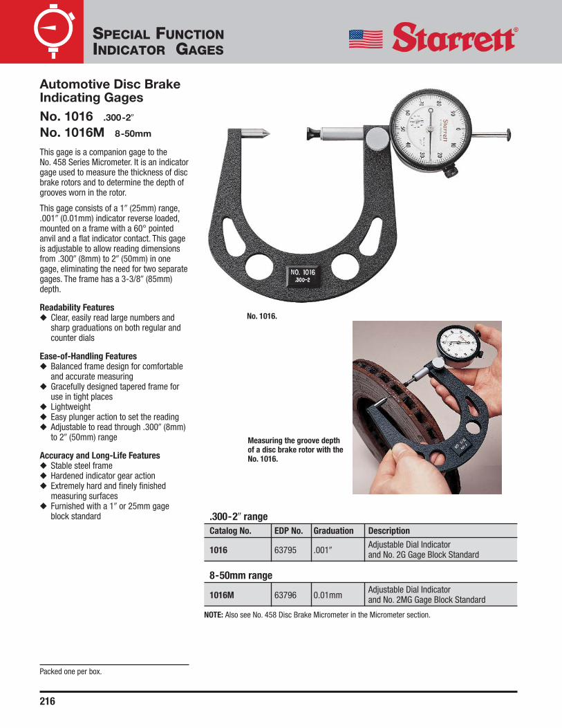
216
.300-2� rangeCatalog No. EDP No. Graduation Description
1016 63795 .001�Adjustable Dial Indicator and No. 2G Gage Block Standard
8-50mm range
1016M 63796 0.01mmAdjustable Dial Indicator and No. 2MG Gage Block Standard
Automotive Disc BrakeIndicating GagesNo. 1016 .300-2�
No. 1016M 8-50mm
This gage is a companion gage to the No. 458 Series Micrometer. It is an indicatorgage used to measure the thickness of discbrake rotors and to determine the depth ofgrooves worn in the rotor.
This gage consists of a 1� (25mm) range,.001� (0.01mm) indicator reverse loaded,mounted on a frame with a 60° pointedanvil and a flat indicator contact. This gageis adjustable to allow reading dimensionsfrom .300� (8mm) to 2� (50mm) in onegage, eliminating the need for two separategages. The frame has a 3-3/8� (85mm)depth.
Readability Features◆ Clear, easily read large numbers and
sharp graduations on both regular andcounter dials
Ease-of-Handling Features◆ Balanced frame design for comfortable
and accurate measuring◆ Gracefully designed tapered frame for
use in tight places◆ Lightweight◆ Easy plunger action to set the reading◆ Adjustable to read through .300� (8mm)
to 2� (50mm) range
Accuracy and Long-Life Features◆ Stable steel frame◆ Hardened indicator gear action◆ Extremely hard and finely finished
measuring surfaces◆ Furnished with a 1� or 25mm gage
block standard
Measuring the groove depth of a disc brake rotor with the No. 1016.
Packed one per box.
NOTE: Also see No. 458 Disc Brake Micrometer in the Micrometer section.
No. 1016.
SPECIAL FUNCTIONINDICATOR GAGES

217
Inch ReadingRange Graduation Dial Reading One Rev. Catalog No. EDP No.
2-1/2–6� 452B 52339
2-1/2–9�.001� 0-100 .100�
452B-9 52341
2-1/10–6� 452E 52342
2-1/10–9� 452E-9 52344
Millimeter Reading63-150mm
0.02mm 0-100 1.0mm452MB 52340
54-150mm 452ME 52343
AccessoriesExtra Handle for Nos. 452B-9, 452MB PT05805-1/2 72175
Extra Handle for Nos. 452E-9, 452ME PT06722 72275
NOTE: Height from contact points to top of handle is 10� (250mm).
Cylinder GagesNo. 452 Series 2-1/10–9�
No. 452M Series 54–150mm
These convenient, easy-to-use gages areused to determine taper and out-of-roundness of bores, offering a quick andaccurate way to show your customerwhether new rings or reconditioning isnecessary.
The ranges are achieved by the use of twomeasuring contact rods. The gage is easilyand accurately set to a micrometer.
Gages also include the following features:◆ Dial is graduated to show plus or minus ◆ Bezel may be rotated for zero setting◆ Sled is hardened and ground for long,
accurate life and has two long-linecontacts in constant alignment with thecylinder wall. These reference points arespring loaded, making the gage self-centering and non-collapsible
◆ The locking screw (stem protrudingabove the dial) clamps the contactpoints in position for measurement witha micrometer
◆ The handle can be locked in anyperpendicular or angular position andmay also be transformed by a slight turninto a toggle joint with a wide sweep
◆ Extra handles may be ordered to make along extension
Packed one in a box.
No. 452B.
SPECIAL FUNCTIONINDICATOR GAGES

218
SPECIAL FUNCTIONINDICATOR GAGES
Dial Indicator Diameter GagesThese gages measure both outside and inside diameters bycomparing dimensions to gage blocks or an adjustablesetting master. Each gage consists of a strong rectangularbox beam with a sensitive gaging contact at one end and areference gaging contact at the other.
All of the diameter gages have these features:◆ The sensitive contact transfers dimensions to the dial
indicator through a linear friction-free mechanism◆ There are two gage feet at the reference end of the gage
and one foot at the sensitive end of the gage to set thegage on the work and align the contacts
◆ Gage depth is set by adjusting the gage feet up or down◆ A lever-actuated reverse mechanism loads the gage for
either inside or outside diameter measurements
◆ The gage contacts are easily changed to I.D. or O.D.gaging by turning them end for end
◆ Unless otherwise specified, the dial indicator sent withthe gage reads in .0005� increments with a total range of±.030�. The dial has a double row of graduations readingin opposite directions – minus in red and plus in black
◆ On the following pages we list our standard line but tosuit other needs we also can furnish the following:
1. Any length that is required2. Any dial indicator with inch or millimeter reading3. No. 717 Electronic Gage Amplifier and Gaging Head in
place of the indicator4. Electronic indicators can also be furnished on any of
these gages except the No. 11025. Special contact shapes6. Gaging contacts with more depth
A
DE
CC
B
Dial Indicator Diameter GagesNo. 1102 1-12�
No. 1102M 25-300mm
This is a light, easy-to-handle gage that is a workhorsein its range. Approximate weight is 1 lb., 12 oz. (0.8kg).The gaging depth can be set within a range of 0-1�(0-25mm) by adjusting the rest foot.Dial indicators are the No. 81-136-623 Inch Reading(.0005�) or No. 81-181-623 Millimeter Reading(0.01mm) models.
The gage should be checked against our No. 1127Master for a precise reference standard duringproduction gaging. (See the following pages.) Alsoavailable on request with .0001� or 0.002mmgraduations.
See specifications on next page.
Photo Key Description
A Range Lock Screw
B I.D.-O.D. Preload ReversingMechanism Lever
C Rest Foot
D Reference Contact
E Sensitive Contact

219
SPECIAL FUNCTIONINDICATOR GAGES
Sent without case unless otherwise ordered.
Length Range Height Adjustment Catalog No. EDP No.
1-12� 0-1� 1102 56134
1-12" 0-1" 1102-1 69004
25-300mm 0-25mm 1102M 65020
CaseStorage Case to Hold Both Gage and No. 1127 Master 1102ZZ 56136
Dial Indicator Diameter Gages (continued)
Nos. 1102, 1102M Series
REVERSIBLE
REVERSIBLE
NO. 7 SPECIAL FORMCONTACT .062�DIAMETER BALL
STANDARDAGDCONTACT.250�
DIAMETERCARBIDETIPPED BALL
FLANGEGROOVECONTACT.100� MAX.
SPECIAL CONTACTS DESIGNED TO ORDER
.49� RADIUS
.030� RADIUS
STANDARD CONTACTS FURNISHED WITH GAGE
SEE VIEW A
1�MIN. I.D.
LOCK SCREW
INTERNAL-EXTERNAL – FULL ADJ. RANGE 1-12�
GAGINGDEPTH 0-1�;1-2� TOORDERSPACER USED WITH REFERENCE CONTACT
WHEN GAGING WITHOUT REST FEET
ROLL TYPE GAGE REST FEET;ONE FRONT, TWO REAR
.0005 DIAL INDICATOR; OTHERGRADUATIONS CAN BE SUBSTITUTED
NO. 1102
VIEW A

220
SPECIAL FUNCTIONINDICATOR GAGES
A
D E F G H
BC
Dial Indicator DiameterGagesNo. 1101 Series 12-60�
No. 1101M Series300-1500mm
These gages allow for measurementbeyond the size range of our No. 1102models. Each gage adjusts a full 6� or 150mm. The contact carriers are verticallyadjustable to handle various work depth.Special contacts are available.
This tool has dowel (line) contacts at oneend of the gage feet, and a button (point)contact gage at the other end of the feet.These can be reversed as needed and thegaging depth can be set within a range of 2-3/4� or 70mm.
This gage should be checked against ourNo. 1126 Master for a precise referencestandard during production gaging. (See thefollowing pages.)
Photo Key Description
A Dial Indicator Fine-Adjusting Screw
B Beam – Rectangular Box Section
C Contact for Added Applications
D I.D.-O.D. Preload Reversing Mechanism Lever
E Combination Dowel/Button Rest Feet
F Sensitive Contact
G Reference Contact
H Mounting Plate with Combination Dowel and Button Rest Feet
5/8�(16)
ADJUSTABLE GAGING EXTERNAL
MIN. MAX. GAGEREST ADJ.
3/4� (19)
2-3/8� (60) MAX.BELOW PLANE X
PT07215
BUTTONTYPE REST
DOWELTYPE REST
3.00�(75)
3/8� (9.5) MAX.ABOVE PLANE X
WILL CLEAR 11/16� (17)
ADJUSTABLE GAGING INTERNAL PT06632-7
PLANE X
Length Inch Reading Millimeter Reading Inch Reading Millimeter Reading.0005� Graduations .01mm Graduations .0001� Graduations .002mm Graduations
Inch mm Catalog No. EDP No. Catalog No. EDP No. Catalog No. EDP No. Catalog No. EDP No.
12-18� 300-450mm 1101-18 53144 1101M-450 65015 1101-18-1 69005 1101M-450-2 69021
18-24� 450-600mm 1101-24 53146 1101M-600 65016 1101-24-1 69006 1101M-600-2 69022
24-30� 600-750mm 1101-30 53148 1101M-750 65017 1101-30-1 69007 1101M-750-2 69023
30-36� 750-900mm 1101-36 53150 1101M-900 65018 1101-36-1 69008 1101M-900-2 69024
36-42� 900-1050mm 1101-42 53152 1101M-1050 65019 1101-42-1 69009 1101M-1050-2 69025
42-48� 1050-1200mm 1101-48 53154 1101M-1200 65021 1101-48-1 69010 1101M-1200-2 69026
48-54� 1200-1350mm 1101-54 53156 1101M-1350 65022 1101-54-1 69011 1101M-1350-2 69027
54-60� 1350-1500mm 1101-60 53158 1101M-1500 65023 1101-60-1 69012 1101M-1500-2 69028
Gaging Contact Range: ±.050� ±1.3mm ±.050� ±1.3mm
NOTE: Sent without case unless otherwise ordered. To order case, specify the Catalog No. and “ZZ” (For example: No. 1101ZZ-18).

221
SPECIAL FUNCTIONINDICATOR GAGES
Heavy-Duty DialIndicator DiameterGagesNo. 1100 Series 12-60�
No. 1100M Series 300-1500mm
These gages combine heavy-dutyconstruction features with adaptability for a wide range of internal and externalmeasurements. The adjustable dowel restlegs ride on slotted mounting plates forhorizontal adjustment. Each of the legs arevertically adjustable to obtain the properrest position on the work and correctalignment on the gaging contacts. 2� or 50 mm range is the vertical adjustment.
The gaging contacts are radiused but maybe modified by request to suit specialgaging conditions.
The indicator and its housing can berotated through to 360º so that theindicator may be read at the mostconvenient angle. The gage should bechecked against our No. 1126 Master for a precise reference standard duringproduction gaging. (See the followingpages.)
A
BC D
E
F G
H
I J
K
Photo Key Description
A I.D.-O.D. Preload Reversing Mechanism Lever
B Tamper Proof Dial Indicator Fine-Adjust Screw
C Beam – Rectangular Box Section
D, E Adjustable Dowel Rest Leg
F, K Dowel Rest
G Sensitive Contact
H Slotted Rest Leg Mounting Plate
I Reference Contact
J Reference Contact Carrier
1-3/16� (30)
ADJUSTABLE GAGING EXTERNAL3.00� (75)
1/8� (3) MAX. BELOWPLANE X
.030R±.001�
2.00 (50) MAX. DROP
1-3/16� (30)
WILL CLEAR 3-1/4� (81)
ADJUSTABLE GAGING INTERNAL
PT30114
PLANE X
5/8�(16)
Length Inch Reading Millimeter Reading Inch Reading Millimeter Reading.0005� Graduations .01mm Graduations .0001� Graduations .002mm Graduations
Inch mm Catalog No. EDP No. Catalog No. EDP No. Catalog No. EDP No. Catalog No. EDP No.
12-18� 300-450mm 1100-18 53128 1100M-450 65024 1100-18-1 69013 1100M-450-2 69029
18-24� 450-600mm 1100-24 53130 1100M-600 65025 1100-24-1 69014 1100M-600-2 69030
24-30� 600-750mm 1100-30 53132 1100M-750 65026 1100-30-1 69015 1100M-750-2 69031
30-36� 750-900mm 1100-36 53134 1100M-900 65027 1100-36-1 69016 1100M-900-2 69032
36-42� 900-1050mm 1100-42 53136 1100M-1050 65028 1100-42-1 69017 1100M-1050-2 69033
42-48� 1050-1200mm 1100-48 53138 1100M-1200 65029 1100-48-1 69013 1100M-1200-2 69034
48-54� 1200-1350mm 1100-54 53140 1100M-1350 65030 1100-54-1 69013 1100M-1350-2 69035
54-60� 1350-1500mm 1100-60 53142 1100M-1500 65031 1100-60-1 69020 1100M-1500-2 69036
Gaging Contact Range: ±.050� ±1.3mm ±.050� ±1.3mm
NOTE: Sent without case unless otherwise ordered. To order case, specify the Catalog No. and “ZZ” (For example: No. 1101ZZ-18).

222
SPECIAL FUNCTIONINDICATOR GAGES
These setting masters are used to check and reset diametergages under production gaging conditions. Each masterconsists of a rigid box beam with reference and sensitiveheads which are individually adjustable along dovetail ways.
A platen on each head locates the diameter gage from itsfeet. The position of the gage contacts is matched by theanvils on the masters which are vertically adjustable. Thereference head anvil has a fine adjustment for final settings,plus a restrictor to help position the gage in the master.
Both heads can be reversed for I.D. or O.D. settings. Eachmaster has a fixed single point rest and two leveling screwswhich provide a three-point suspension. All contact andworking surfaces are hardened and ground.
The setting procedure is as follows: set the diameter gageprecisely to gage blocks or height gages. Then, using thediameter gage, set the master which can then be used as aprecise reference standard for the diameter gage duringproduction gaging.
Setting Masters For Dial Indicator Diameter Gages
A
B C D
E F G
SENSITIVE AND REFERENCE HEADS TOBE REVERSED AS SHOWN IN PHANTOMFOR INTERNAL MEASUREMENT
GAGE RESTPAD SURF.
SET 5.25-12� (133.4-304.8)EXTERNAL MEASUREMENT
SET 1-12� INTERNAL (25.4-304.8)
MEASUREMENT
0-2� ADJ. DROP(50)
0-2� ADJ.DROP
DOVETAIL HARDENED WAYSDOVETAIL LOCKS
Internal-ExternalAdjustable SettingMaster for Starrett No. 1102 Diameter GagesCatalog No. 1127EDP 56135This set master is used with our No. 1102Diameter Gages. The internal adjustmentrange is 1–12� (25-300mm) and externaladjustment is 5-1/4–12� (133-300mm).Storage case is available to hold both thegage and master (Catalog No. 1102ZZ,EDP 56136).
PhotoKey Description
A Sensitive Head
B Hardened Rest Platen
C Anvil
D Reference Head
PhotoKey Description
E Fixed Single Point Button Rest
F Beam – Rectangular Box Section
G Leveling Screws (2)

223
SPECIAL FUNCTIONINDICATOR GAGES
A
B C D
EF G
Internal-ExternalAdjustable SettingMasters for StarrettNos. 1100 and 1101Series Diameter GagesNo. 1126 Series 12-60� (300-1500mm)
These set masters are used to check and reset Starrett Nos. 1100 and 1101 Diameter Gages under production gaging conditions.The range is from 12-60� or 300-1500mm.
PLANE X .250� (6.3)ABOVE PLANE X
STRAIGHT-FACEDMASTER ANVIL NIBSSEE DETAIL (1) BELOW
Angular or Conical Nibs and Riser Blocks Quoted Upon Request
DETAIL (1)
ANGULAR OR CONICAL FACE MASTERANVIL NIBS CAN BE FURNISHED ANDARE INTERCHANGEABLE WITH THESTRAIGHT FACED NIBS
DETAIL (2)
RISER BLOCK SETS CAN BEFURNISHED IN INCREMENTS OF2� (50) TO GAGE DEPTH SETTINGRANGE UP TO 6� (150) MAXIMUM
2.00� (50) MAX. BELOW PLANE X. SEE DETAIL (2)
RISERBLOCK
Photo Key Description
A Sensitive Head
B Hardened Rest Platen
C Anvil
D Reference Head
E Leveling Screws (2)
F Beam – Rectangular Box Section
G Fixed Single Point Button Rest
Length Range For Use With Diameter Gage Nos.
Inch mm Inch mm Inch mm Catalog No. EDP No.
12-18� 300-450mm 1100-18 1100M-450 1101-18 1101M-450 1126-18 53160
18-24� 450-600mm 1100-24 1100M-600 1101-24 1101M-600 1126-24 53161
24-30� 600-750mm 1100-30 1100M-750 1101-30 1101M-750 1126-30 53162
30-36� 750-900mm 1100-36 1100M-900 1101-36 1101M-900 1126-36 53163
36-42� 900-1050mm 1100-42 1100M-1050 1101-42 1101M-1050 1126-42 53164
42-48� 1050-1200mm 1100-48 1100M-1200 1101-48 1101M-1200 1126-48 53165
48-54� 1200-1350mm 1100-54 1100M-1350 1101-54 1101M-1350 1126-54 53166
54-60� 1350-1500mm 1100-60 1100M-1500 1101-60 1101M-1500 1126-60 53167
NOTE: Setting masters for larger diameters are also available by request – priced on the application.
Sent without case. Cases are available to hold gage and master. To order case, specify the Catalog No. and “ZZ” (For example: 1126ZZ-18).

224
SPECIAL FUNCTIONINDICATOR GAGES
Dial Depth GagesNo. 640 Series 0-1/2�
No. 640M Series 0-10mm
No. 643 0-.125�
No. 644 0-3�
No. 644M 0-75mm
See Page 137 for complete details.
Left-to-right: Nos. 640JZ, 643JZ, 644JZ.
Top Reading Dial Depth GagesNo. 642 Series 0-8.6�
No. 642M Series 0-215mm
See Page 138 for complete details.
Left, No. 642AZ side view; right, top view.
Special Function Dial Gages – A Final NoteIn addition to the products detailed in this section, we have made many other special function gages to suit a wide variety of ourcustomers’ specific requirements.
If you have a special application, we invite you to submit your drawings and specifications to our Special Order Department at 121Crescent Street, Athol, MA 01331, USA . We will be happy to provide a prompt quotation.

J.W. DONCHIN CO.Precision Measuring Equipment and Industrial Supplies since 1924.
www.jwdonchin.com
4841 W. Chicago Ave. - Chicago, IL 60651 • Phone: 773-261-2182 • Fax: 773-261-2867 • [email protected]
J.W. DONCHIN CO.
J.W. Donchin Co. was established in 1924 and has been known world wide ever since. Customer Service is our Main Focus. We offerExpert Product Knowledge, Large Stocking Inventory and Competitive Pricing to assist you in locating and selecting the correcttool or product to fit your needs. (J.W. Donchin Co. is one of L.S. Starrett’s largest stocking distributors.)
Contact Information:
Phone: 773-261-2182
Fax: 773-261-2867
Email: [email protected]
Direct Access Links (View specific information, click on any of the following)
• Latest Website Updates:
• Website:
• Quotes:
• Latest Promos:
• Line Card (Product Lines & Mfg)
Catalog / Promo / Pricelist
• Starrett
• Mitutoyo
• Fowler
• Brown & Sharpe