dgps survey report
TRANSCRIPT

Name of the Applicant: Executive Engineer,
Public Work Department,
National Highway Division,
Jagdalpur (C.G).
D.G.P.S. SURVEY REPORT FOR
CONSTRUCTION OF APPROACH ROAD & HIGH
LEVEL BRIDGE AT KM 337.200
(SINGAR BAHAR RIVER) OF NH-63 (OLD NH-16)
BHOPALPATANAM TO JAGDALPUR road
FOREST DIVISION BIJAPUR
DISTRICT BIJAPUR
CHHATTISGARH
INDEX
MAPS ON A3 SIZE PRINTOUT
S. No. PARTICULARS 1 LOCATION MAP
2 GEO REFERENCE SURVEY SITE ON SOI TOPOSHEET
3 SURVEY SITE WITH BASE STATION POINTS
4 SURVEY SITE SUPERIMPOSE ON GOOGLE IMAGE
5 SURVEY SITE ON SATELLITE IMAGE
6 SURVEY SITE ON SOI TOPOSHEET IN A0 SIZE
DATA ENCLOSED IN SOFT COPY
S. NO. PARTICULARS 1 SURVEY REPORT
2 KML FILE
3 SHP FILE
4 MAPS IN JPEG & PDF FORMAT
S. No. PARTICULARS
1 ABOUT US
2 INTRODUCTION TO DGPS
3 INTRODUCTION TO SURVEY SITE
4 METHODOLOGY USED
5 CONTROL POINTS
6 SURVEY DATE & PHOTOGRAPHS

1. ABOUT US
Computer Plus an ISO 9001:2015 certified organization working in the field of I.T. Consulting & Software Services. We are registered organization
under Directorate of Geology and Mining, Chhattisgarh. We are serving since 1998 & head office in Raipur, (C.G.), with core competence in the areas of Integrated Business Solutions with Implementation and Support.
Our Team:
We're justifiably proud of the team we've assembled. Initially numbering just two programmers, Computer Plus has grown steadily and now has over
250 staff members. The Computer Plus team is made up of highly-qualified, talented and innovative IT and GIS professionals each with their own area of expertise. Their experience spans the full range of custom software
development, from small entrepreneurial projects to complex systems for major corporations.
Our Mission:
Computer Plus's mission is to solve challenging technical problems in
partnership with our clients. How we achieve it:
We understand the business needs of our clients, and how technology can be a tool to make modern businesses more profitable for both private and government sector.
Computer Plus combines technical excellence with great customer service and value for money.
We value creativity and collaboration; ideas are shared and everybody
contributes on an individual basis toward the common goal.
We create new teams for each project, ensuring the best possible
combination of skills and experience to meet the client's needs and deliver
high quality solutions.

2. INTRODUCTION TO DGPS
The term DGPS is sometimes used to refer to differential GPS that is based on pseudo ranges, aka code phase. Even though the accuracy of code phase applications was given a boost with the elimination of Selective Availability (SA) in May 2000 consistent accuracy better than the 25 meter range still requires reduction of the effect of correlated ephemeris and atmospheric errors by differential corrections. Though the corrections could be applied in post-processing services that supply these corrections, most often operate in real-time. In such an operation pseudo range based versions can offer meter or even sub meter results.
Usually, pseudo range corrections are broadcast from the base to the
rover or rovers for each satellite in the visible constellation. Rovers with an
appropriate input/output (I/O) port can receive the correction signal and
calculate coordinates. The real-time signal comes to the receiver over a data
link. It can originate at a project specific base station or it can come to the
user through a service of which there are various categories. Some are open
to all users and some are by subscription only. Coverage depends on the
spacing of the beacons, aka transmitting base stations, their power,
interference, and so forth. Some systems require two-way, some one-way,
communication with the base stations. Radio systems, geostationary
satellites, lowearthorbiting.

SURVEY METHOD
1 RTK (Real Time Kinematic)
2 STATIC METHOD
1 Real-time Kinematic
Most, not all, GPS surveying relies on the idea of differential positioning.
The mode of a base or reference receiver at a known location logging data at
the same time as a receiver at an unknown location together provide the
fundamental information for the determination of accurate coordinates. While
this basic approach remains today, the majority of GPS surveying is not done
in the static post-processed mode. Post-processing is most often applied to
control work. Now, the most commonly used methods utilize receivers on
reference stations that provide correction signals to the end user via a data
link sometimes over the Internet, radio signal, or cell phone and often in real-
time.
In this category of GPS surveying work there is sometimes a distinction
made between code based and carrier based solutions. In fact, most
systems use a combination of code and carrier measurements so the
distinction is more a matter of emphasis rather than an absolute difference.
Well that's a bit of discussion about static surveying, but as you know, a
good deal of GPS these days is done not static. Much work is now done with
DGPS or real-time kinematic, RTK.
Errors in satellite clocks, imperfect orbits, the trip through the layers of
the atmosphere, and many other sources contribute inaccuracies to GPS
signals by the time they reach a receiver.
These errors are variable, so the best to way to correct them is to monitor them as they happen. A good way to do this is to set up a GPS receiver on a

station whose position is known exactly, a base station. This base station receiver’s computer can calculate its position from satellite data, compare that position with its actual known position, and find the difference. The resulting error corrections can be communicated from the base to the rover. It works well, but the errors are constantly changing so a base station has to monitor them all the time, at least all the time the rover receiver or receivers are working. While this is happening the rovers move from place to place collecting the points whose positions you want to know relative to the base station, which is the real objective after all. Then all you have to do is get those base station corrections and the rover’s data together somehow. That combination can be done over a data link in real-time, or applied later in post processing.
Real-time positioning is built on the foundation of the idea that, with the
important exceptions of multipath and receiver noise, GPS error sources are
correlated. In other words, the closer the rover is to the base the more the
errors at the ends of the baseline match. The shorter the baseline, the more
the errors are correlated. The longer the baseline, the less the errors are
correlated.
The base station is at a known point, whether it was on a building
permanently or it's a tripod mounted base station. The fact that it is in a
known position allows the base station to produce corrections. The
constellation is telling the base station that it is in a slightly different place, so
corrections can be created to sent to the rover at the unknown point. The
corrections are applied in real time.
RADIAL GPS
Such real-time surveying is essentially radial. There are advantages to the approach. The advantage is a large number of positions can be established in a short amount of time with little or no planning. The disadvantage is that there is little or no redundancy in positions derived, each of the baselines originates from the same control station. Redundancy can be incorporated, but it requires repetition of the observations so each baseline is determined with more than one GPS constellation. One way to do it is to occupy the

project points, the unknown positions, successively with more than one rover. It is best if these successive occupations are separated by at least 4 hours and not more than 8 hours so the satellite constellation can reach a significantly different configuration.
RTK and DGPS are radial. You have a known point in the middle, the base, and then the unknown points around it. This provides little geometric solidity. If there's an error in one of these radial base lines, it would be tough to catch it because there's no real redundancy. The illustration shows a way around this difficulty. There are two receivers, A and B, and it's possible by double occupation, one receiver going one way and the other going the other, by double occupying the unknown points to get some redundancy and some checks against the positions from a base. Another way to do it is to use one receiver. That receiver would occupy each points twice with four to eight hours between the first occupation and the second occupation on the point. Another way is to move the base to another known point. Then if you have vectors from another base into these points, you have a check. This approach allows a solution to be available from two separate control stations. Obviously, this can be done with reoccupation of the project points after one base station has been moved to a new control point, or a two base stations can be up and running from the very outset and throughout of the work as would be the case using two CORS stations. It is best if there are both two occupations on each point and each of the two utilize different base stations.
A more convenient but less desirable approach is to do a second
occupation almost immediately after the first. The roving receiver’s antenna is
blocked or tilted until the lock on the satellites is interrupted. It is then
reoriented on the unknown position a second time for the repeat solution.
This does offer a second solution, but from virtually the same constellation.
More efficiency can be achieved by adding additional roving receivers.
However, as the number of receivers rises, the logistics become more
complicated, and a survey plan becomes necessary. Also, project points that
are simultaneously near one another but far from the control station should
be directly connected with a baseline to maintain the integrity of the survey.
Finally, if the base receiver loses lock and it goes unnoticed, it will completely
defeat the radial survey for the time it is down.
These are a few possibilities to consider when you are doing a real-time survey.
An advantage to continuously operating reference station network is that
since those bases are operating simultaneously and all the time, it's possible
to download the positions from more than one base and process your new
position based on these continuously operating reference stations and have
some redundancy.

2. STATIC METHOD
I. Rapid Static Method
II. Traverse Method
III. Trilateration Method

3. METHODOLOGY USED
SURVEY METHODLOGY UNDER LINEAR PROJECT
z
UNDER LINEAR PROJECT TRIANGULATION METHOD WILL BE FOLOWED
USING THIS PBM AS A CORRECTION POINT WE HAVE TO COLLECT OTHER BOUNDARY POINTS
COLLECTED DATA HAVE TO
BE SUPERIMPOSE ON
TOPOSHEET MAP WHICH
HAVE BEEN COLLECTED
FROM SURVEY OF INDIA
COLLECTED DATA HAVE
TO BE SUPERIMPOSE ON
CADASTRAL MAP WHICH
HAVE BEEN COLLECTED
FROM GOVERNMENT DEPARTMENT
COLLECTED DATA HAVE TO
BE SUPERIMPOSE ON
SATELLITE IMAGE WHICH
HAVE BEEN COLLECTED
FROM NRSC HYDERABAD
REPORT PREPARATION & MAP PREPARED AS PER REQUIRED SCALE

4. INTRODUCTION TO SURVEY SITE
The surveyed area for Construction of Approach Road & High Level
Bridge at Km 337.200 (Singar Bahar River) of NH-63 (Old NH-16)
Bhopalpatanam to Jagdalpur Road is located on Village
Chinnakodepal, which comes under Block Usur & Bijapur, District
Bijapur, Chhattisgarh. Bijapur Bus Stand longitude latitude is
80°48'55.96"E 18°47'7.56"N. Survey site is located 6.9 Km from
Bijapur. Survey site comes under Forest Division Bijapur, Forest
Range Bijapur and Forest Circle Jagdalpur.
AREA DETAILS & LAND CLASSIFICATION OF RESERVE FOREST
S.No. District Name Division Name Block Name Compartment No. Area (In Hectare)
1 Bijapur
Bijapur
Bijapur RF 212 0.453
2 Usur RF 213 0.467
TOTAL 0.920
LAND DESCRIPTION
S.No. Land Description Width (In Meters) Length (In Meters)
1 BRIDGE 16 100.00
2 APPROACH ROAD 20 379.96
TOTAL 479.96

5. CONTROL POINT
PRIMARY CONTROL POINT (FIXING OF BASE STATION POINT)
S.No. P.C.P VILLAGE NAME LONGITUDE LATITUDE
GROUND CONTROL POINT 1 Chinnakodepal
80° 45' 36.502" E 18° 46' 53.357" N
GROUND CONTROL POINT 2 80° 45' 33.732" E 18° 46' 49.093" N
SURVEYED GROUND CONTROL POINTS
S.No. PILLAR ID LONGITUDE LATITUDE
1 C1 80° 45' 37.543" E 18° 46' 53.751" N
2 C2 80° 45' 36.752" E 18° 46' 53.318" N
3 C3 80° 45' 35.849" E 18° 46' 52.537" N
4 C4 80° 45' 35.079" E 18° 46' 51.905" N
5 C5 80° 45' 34.308" E 18° 46' 51.274" N
6 C6 80° 45' 33.322" E 18° 46' 49.945" N
7 C7 80° 45' 32.337" E 18° 46' 48.616" N
8 C8 80° 45' 31.346" E 18° 46' 47.361" N
9 C9 80° 45' 30.363" E 18° 46' 46.658" N
10 C10 80° 45' 29.115" E 18° 46' 45.995" N
11 C11 80° 45' 27.904" E 18° 46' 45.239" N
12 C12 80° 45' 26.674" E 18° 46' 44.373" N
13 C13 80° 45' 25.444" E 18° 46' 43.508" N
14 L1 80° 45' 37.713" E 18° 46' 53.469" N
15 L2 80° 45' 36.954" E 18° 46' 53.054" N
16 L3 80° 45' 36.072" E 18° 46' 52.290" N
17 L4 80° 45' 35.301" E 18° 46' 51.659" N
18 L5 80° 45' 34.531" E 18° 46' 51.027" N
19 L5A 80° 45' 34.492" E 18° 46' 51.070" N
20 L6 80° 45' 33.526" E 18° 46' 49.768" N
21 L7 80° 45' 32.610" E 18° 46' 48.421" N
22 L7A 80° 45' 32.555" E 18° 46' 48.460" N
23 L8 80° 45' 31.588" E 18° 46' 47.130" N
24 L9 80° 45' 30.569" E 18° 46' 46.398" N
25 L10 80° 45' 29.292" E 18° 46' 45.717" N
26 L11 80° 45' 28.099" E 18° 46' 44.972" N
27 L12 80° 45' 26.873" E 18° 46' 44.109" N
28 L13 80° 45' 25.647" E 18° 46' 43.246" N
29 R1 80° 45' 37.373" E 18° 46' 54.033" N
30 R2 80° 45' 36.522" E 18° 46' 53.559" N
31 R3 80° 45' 35.623" E 18° 46' 52.780" N
32 R4 80° 45' 34.854" E 18° 46' 52.150" N
33 R5 80° 45' 34.085" E 18° 46' 51.520" N

S.No. PILLAR ID LONGITUDE LATITUDE
34 R5A 80° 45' 34.130" E 18° 46' 51.471" N
35 R6 80° 45' 33.102" E 18° 46' 50.098" N
36 R7 80° 45' 32.064" E 18° 46' 48.812" N
37 R7A 80° 45' 32.118" E 18° 46' 48.773" N
38 R8 80° 45' 31.102" E 18° 46' 47.593" N
39 R9 80° 45' 30.177" E 18° 46' 46.931" N
40 R10 80° 45' 28.928" E 18° 46' 46.267" N
41 R11 80° 45' 27.701" E 18° 46' 45.500" N
42 R12 80° 45' 26.471" E 18° 46' 44.635" N
43 R13 80° 45' 25.241" E 18° 46' 43.769" N
LENGTH IN BETWEEN SURVEYED GROUND CONTROL POINTS
POINT NAME LENGTH (In Meters)
POINT NAME LENGTH (In Meters)
C1 - C2 26.71
L7 - L8 49.69
C2 - C3 35.71
L8 - L9 37.39
C3 - C4 29.76
L9 - L10 42.84
C4 - C5 29.76
L10 - L11 41.75
C5 - C6 50.00
L11 - L12 44.63
C6 - C7 50.00
L12 - L13 44.63
C7 - C8 48.28
R1 - R2 28.87
C8 - C9 35.98
R2 - R3 35.57
C9 - C10 41.84
R3 - R4 29.69
C10 - C11 42.39
R4 - R5 29.69
C11 - C12 44.77
R5 - R5A 2.00
C12 - C13 44.77
R5A - R6 51.84
L1 - L2 25.63
R6 - R7A 49.88
L2 - L3 34.89
R7A - R7 2.00
L3 - L4 29.76
R7 - R8 46.86
L4 - L5 29.76
R8 - R9 33.88
L5 - L5A 1.75
R9 - R10 41.89
L5A - L6 49.00
R10 - R11 42.94
L6 - L7A 49.23
R11 - R12 44.77
L7A - L7 2.00
R12 - R13 44.77

6. SURVEY DATE
Survey Date Survey Time Village Name
16-04-2019 11.55 AM To 05.30 PM Chinnakodepal
Weather was nice with clear sun light. Survey pillar marking has been
done before itself so it was easy to get the location point. Survey has
been done by the survey team members Mr. Santosh Sahu, Mr. Rahul
Bhoi and Mr. Amit Loha. The team was lead by Mr. Santosh sahu.
Base Station Photographs
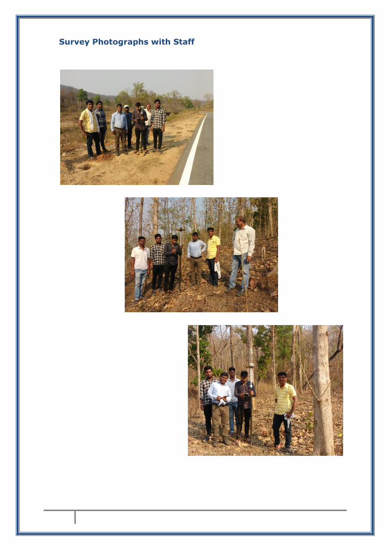
Survey Photographs with Staff

DGPS SURVEY & REPORT PREPARED BY:
COMPUTER PLUS
Software Development & Consultancy
Plot No. 4 Sector-1, Devendra Nagar Raipur (C.G.) 492001 Phone No: 0771 4031077 M : 7587113793 E-mail: [email protected] Website: www.cplus.in
Service providing
GPS & DGPS Land Survey
GIS ANALYSIS WORKS
GIS MAPPING & TOPOLOGICAL SURVEY
MAP DIGITIZATION
SOFTWARE DEVELOPMENT & WEB DESIGNING
MOBILE & WEB APPS
DATA ANALYSIS WORK