developments in fluidized bed conversion of solid fuels online-first/0354... · developments in...
TRANSCRIPT

1
DEVELOPMENTS IN FLUIDIZED BED CONVERSION OF SOLID FUELS
BO LECKNER
Dept. Energy and Environment, Chalmers University of Technology, 41296 Göteborg, Sweden
Email: [email protected]
A summary is given on the development of fluidized bed conversion (combustion and
gasification) of solid fuels. First, gasification is mentioned, following the line of
development from the Winkler gasifier to recent designs. The combustors were initially
bubbling beds, which were found unsuitable for combustion of coal because of various
drawbacks, but they proved more useful for biomass where these drawbacks were absent.
Instead, circulating fluidized bed boilers became the most important coal converters,
whose design now is quite mature, and presently the increments in size and efficiency are
the most important development tasks. The new modifications of these conversion devices
are related to CO2 capture. Proposed methods with this purpose, involving fluidized bed,
are single-reactor systems like oxy-fuel combustion, and dual-reactor systems, including
also indirect biomass gasifiers.
Key words: fluidized bed; combustion; gasification; chemical looping; oxy-fuel; calcium
looping.
1. Introduction
The development of fluidized bed conversion (FBC) during the last hundred years is illustrated
in fig. 1, where various lines of evolution are seen.
Figure 1. Fluidized bed conversion history. The lines show the main paths of development.
It is the purpose of this article to make a concise survey over the historic period covered by fig.
1, commenting on the various lines of development and their connections.
Single reactor FB
Twin reactor FB
1920 1930 1940 1950 1960 1970 1980 1990 2000 2010
* Winkler gasifier HTW Gasifier , BFB , lignite Uhde Gasifier
USSR BFB all solid fuels BFB
CFB
YEAR
BFB , lignite BFB
Lewis & Gilliland ( Cat Cracker , petroleum )
Kunii, Pyrox Güssing gasifier , biomass & waste Calcium looping and other post combustion methods
CLC , all fuels
*
*
biomass & wastes
all solid fuels
PFBC coal * *

2
2. The Winkler line
The technical development of FBC was first manifested in 1922 in a patent by Winkler [1] on a
bubbling fluidized bed gasifier. Almost 40 units of this type were built for production of syngas for the
chemical industry, starting 1926 in Leuna (Germany) and ending in 1975. The Winkler gasifier is a
“direct gasifier” where some combustion by air or oxygen is performed in the gasifier bed to produce
heat for the endothermic gasification
reactions and for heating of the fuel and
the bed.
A drawing of an early version of
the gasifier in fig. 2a shows a rather large
refractory-lined reactor whose cross
section is up to 5 m in diameter, with
staged steam/oxygen supply, and an
arrangement for extracting the ashes
from the bottom. From the drawing it is
evident that particles were also carried
away with the gas. Well-known
drawbacks during operation with coal
(lignite) were clinkering, limiting the operation temperature to less than 1040 oC, tar formation at this
“low” temperature, and loss of char in the removed bottom and fly ashes.
This type of gasifier was improved in a design called High-Temperature Winkler (HTW)
gasifier in Germany, shown in fig. 2b, introduced in 1974 and successfully developed till the year
1997 for applications in power generation and production of methanol [2]. At that year the work was
stopped: it was not economical to produce syngas from lignite. A later effort in commercialization
aimed at power production in combined cycle, but high-efficiency Rankine cycle with pulverized coal
was finally preferred. Recently (2011), the manufacturing rights of the HTW gasifier were taken over
by the German company Thyssen-Krupp-Uhde. One of the projects carried out by that company was a
study of a 111 MWfuel HTW gasifier for production of methanol by gas from biomass in Sweden.
During the last 30 years many gasification units of the same kind as the Winkler gasifier have
been built, employing biomass. However, most of them were stopped for economic reasons. An
example of a recent successful plant is the 2x80 MWfuel gasifier in Lahti, Finland [3] using biomass
and sorted waste. The product gas is cooled and filtered at about 400 oC before it is burned in a boiler.
This arrangement has several advantages: the filter temperature permits removing the fly ashes in a
solid form, including alkali compounds and many of the heavy metal contained in waste. At the same
time most of the tars do not condense. Hence, the connected boiler burns cleaned gas and is no longer
a waste boiler, which otherwise would have made the boiler more expensive and prevented co-
combustion with other types of fuel. Moreover, the corrosion propensity of the gas is reduced and high
steam data can be used, which increases the efficiency of electric power production compared to what
is normal in waste boilers.
3. Combustors
3.1 Bubbling fluidized bed (BFB) boilers at atmospheric pressure
The first effort to burn solid fuels in a fluidized bed was made in the Soviet Union after World
War II [4] with the purpose of developing boilers for industry and district heating. Figure 3a shows a
drawing of one of the prototypes. The coal was to some extent gasified in the bed and no horizontal
cooling tubes were used there; the gases produced were burnt in the freeboard by secondary air.
a) b)
Figure 2. a) Early Winkler gasifier. b) Modern High
Temperature Winkler gasifier. (Both are “bubbling”
beds despite the cyclone)

3
Probably there was a problem to avoid slag formation, because in a later publication [5] a
modified design is shown where the fuel is fed on top of the bed, and various ways to control the bed
temperature, among them cooling tubes, are discussed. However, before any commercial plant was
built, natural gas became more attractive in the Soviet Union, and the FBC development lost its
momentum.
Instead, the FBC technology was introduced in China, and thousands of small FBC units were
operating there already during the 1980s [6]. Figure 3b gives an example. Because of the potential
environmental advantages and the ability to burn various types of fuel, the development of BFB
combustors (operated at “low” gas velocities, 1-3 m/s) was taken up also in USA and Europe [8]. One
of the most advanced BFB designs from this region is shown in Fig. 3c. Further examples from the
early activities are found in the book of Oka [9].
After some years of development it became obvious that BFB was a dead end for coal
combustion because of several disadvantages: 1) heavy erosion on in-bed heat-transfer surfaces; 2)
very large bed surface was needed for utility-size boilers, fig. 4; 3) considerable loss of combustible
char; and 4) the sulphur capture was not as good as anticipated.
In a BFB the limestone is contained in the particle phase of the bed, subject to predominantly
reducing conditions, while gas containing oxygen and SO2 passes through the bubbles. In a CFB the
particle phase, even in the bottom part, is more disperse and tends more towards oxidising conditions,
favouring sulphur capture. Particles are also contained in the riser allowing further reactions. As a
result, the sulphur capture is more efficient as seen from fig. 5 [10]: the retention is higher at a smaller
Ca/S ratio than in a BFB. Because of changes in the reducing/oxidizing conditions the optimum is
displaced towards higher temperatures in CFB.
Figure 4. Efforts to design large-scale boilers using BFB [11]. The beds are located in the bottom
part or in cages mounted on the walls.
a) b)
c)
Figure 3. a) FBC boiler built in the USSR in 1950s [4]; b) Chinese 130 t/h FBC boiler from 1980
[6]; c) One of the most developed boilers in this period, Georgetown FBC 50 t/h boiler, 1980 [7]

4
However, the BFB did not disappear: the drawbacks of coal combustion identified above are
less important for biomass and organic waste, both high-volatile fuels, which tend to burn and release
their heat in the freeboard above the dense bed to a large extent, allowing operation of bubbling beds
at reasonable bed temperatures (750-900 oC) without immersed cooling tubes. So, BFBs presently
burn biomass and waste in boilers of up to a few hundred MWth in industrial and district heating
systems [12]. A typical example is given in fig. 6, where the temperature profile reveals how the heat
is released in the furnace. Air is added to the bottom bed and to secondary-air nozzles in the freeboard.
The bottom air meets the volatile gases and reacts above the bed, while combustion in the bed itself is
moderate, maintaining a relatively low bed temperature. The final combustion, promoted by the
secondary air, creates a temperature peak, which might lead to melting of ashes, forming deposits on
the walls. Therefore, to avoid excess temperatures, the secondary air is often added in stages. The
boiler in fig. 6 shows an empty gas pass before the gases enter the convection section. This could have
two reasons: 1) if the boiler is to be used for (prepared) wastes, then (in the European Union) there
must be a gas residence time of at least 2 seconds after the last supply of air at above 850 oC according
to EU’s Waste Directive [13]; 2) to reduce the propensity for corrosion on the final superheater, the
designs often optimize the gas temperature to be relatively close to the tube temperature at the
entrance of the superheater tube bundle.
3.2 Bubbling fluidized bed boilers at higher pressure (PFBC)
The development of PFBC up till 1992 has been clearly described in [14]. Three large-scale
pilot plants were put into operation in 1991 in Spain (Escatrón), USA (Tidd), and Sweden (Värtan).
The first two plants are stopped, but the Swedish one is still in operation as a combined heat and
power plant. The last unit built was the Karita 365 MWe plant in 2001 in Japan. The experience was
relatively positive but some drawbacks became obvious: 1) despite low fluidization velocities some
erosion of in-bed tube bundles was experienced; 2) increase of the flue-gas temperature to levels
permitted by modern gas turbines requires an additional combustion chamber and perhaps a gasifier to
produce the gas needed to be burnt for the enhancement of the flue gas temperature. Although this can
be done, it is a complication, and furthermore, desulphurization of that gas adds to the complexity; 3)
cleaning of the gas by cyclones is possible, but filters are a better solution to protect the gas turbine
from particles and some alkali compounds. However, even if considerable development efforts were
made, reliable high-temperature filters are still not available. Despite the “low” temperature before the
Figure 5. Sulphur capture in a BFB
boiler (16 MWth) (C) and a CFB (40
MWth) boiler (N) operated with coal
under similar conditions and with the
same limestone [10].
Figure 6. BFB boiler for biomass and waste,
showing the temperature profile in the
combustion chamber
5
gas turbine in the plants mentioned, efficiencies of 42% were reached. The thermodynamic advantage
of PFBC remains, but the road chosen in the recent development of FBC is efficiency enhancement in
atmospheric pressure CFB employing supercritical steam data.
3.3 Circulating fluidized bed (CFB) boilers
It was found that operation at higher gas velocities (5-6 m/s), returning the entrained bed
material to the furnace by a particle separator (CFB), is less susceptible to the problems mentioned in
relation to BFB: 1) heat is transferred by the entrained particles to the vertical wall surfaces of the
combustion chamber and to additional vertical surfaces inserted in regions less exposed to erosion than
in the dense fluidized bottom-bed; 2) higher energy density (MW/m2 cross section) makes the
combustion chambers narrower, and therefore the scale-up to larger sizes becomes easier; 3) better
combustion and sulphur capture efficiencies are attained through the longer residence times for small
particles achieved by recirculation.
A dominant design criterion in FBC, as well as in CO2 capture processes involving solid fuel, is
the large gas volume-flow that passes the equipment, especially at fuel-conversion temperature, 800-
900 oC and atmospheric pressure. Just like illustrated by the BFBs in fig. 4, the bed cross-section
becomes large unless the gas velocity is increased like in a CFB. So, from the mid-1980s CFB became
the predominant design for combustion of coal (also for other fuels), employed in a variety of ways, as
illustrated in the survey of fig. 1, including conventional CFB for coal combustion as well as various
modifications for CO2 capture. In low-temperature devices for CO2 removal, applied in the cold end of
the flue-gas pass, the situation is slightly relaxed: the volume flow is only one third to one fourth of
that at high temperatures (300K /1200K), but CFB has been proposed for many applications in this
region too.
The first patent on high-velocity fluidization was obtained by Lewis and Gilliland [15], who
realized that they could achieve greater output from their catalyst-bed reactor if they increased the
fluidization velocity above that normal for a low-velocity fluidized bed. They found that high input of
solids to the bed was necessary to maintain a relatively dense particle suspension in a tall riser and to
avoid emptying the bed. They did not mention the design of the reactor, but in an accompanying
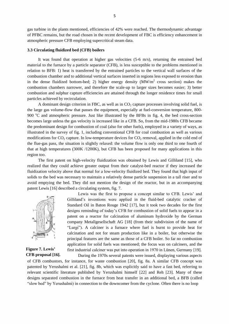
patent Lewis [16] described a circulating system, fig. 7.
Lewis was the first to propose a concept similar to CFB. Lewis’ and
Gilliland’s inventions were applied in the fluid-bed catalytic cracker of
Standard Oil in Baton Rouge 1942 [17], but it took two decades for the first
designs reminding of today’s CFB for combustion of solid fuels to appear in a
patent on a reactor for calcination of aluminum hydroxide by the German
company Metallgesellschaft AG [18] (from their subdivision of the name of
“Lurgi”). A calciner is a furnace where fuel is burnt to provide heat for
calcination and not for steam production like in a boiler, but otherwise the
principal features are the same as those of a CFB boiler. So far no combustion
application for solid fuels was mentioned; the focus was on calciners, and the
first industrial calciner was put into operation in 1970 in Lünen, Germany [19].
During the 1970s several patents were issued, displaying various aspects
of CFB combustors, for instance, for waste combustion [20], fig. 8a. A similar CFB concept was
patented by Yerushalmi et al. [21], fig. 8b, which was explicitly said to have a fast bed, referring to
relevant scientific literature published by Yerushalmi himself [22] and Reh [23]. Many of these
designs separated combustion in the furnace from heat transfer in an additional bed, a BFB (called
“slow bed” by Yerushalmi) in connection to the downcomer from the cyclone. Often there is no loop
Figure 7. Lewis’
CFB proposal [16].

6
seal on the patent drawings. The most important patents related to boilers belong to Metallgesellschaft
[24,25] fig. 8c, based on the previous experience of that company on calciners.
The Lurgi patents [24,25] fig. 8c, having the priority date of 1975, comprise reactor, separator,
recycling conduit for particles, and air supply, organized into two streams: primary and secondary air,
such as is common in combustors of all types. The secondary air could be added in several locations
along the height of the furnace. The lower part of the bed could be downwardly tapered, i.e. with
inclined walls. There is an external fluidized-bed heat exchanger attached to the system, but heat could
also be transferred to tubes in the furnace and in the particle separator. The combustion bed is
characterized by a certain particle density-gradient from the bottom and upwards. It was claimed that
there is no jump in the transition in density between the denser phase in the bottom region and the
upper dust-containing space in accordance with the characteristics of a “fast” fluidized bed (i.e. no
distinct bed surface). In fact, the authors mentioned [22,23] and Kwauk [26] from the Chinese
Academy of Science, independently, were the predominant advocates of the fast-bed concept that
came to play a important role in the interpretation of the fluidized regime prevalent in a CFB reactor.
After these significant development steps of CFB, many patents were awarded, focusing on
details of the process. In fig. 8d just one example is given of a subsequent development: the integrated
particle separator, which considerably simplified the boiler structure, and contributed to the market
success of the company involved, Foster Wheeler (after purchasing Ahlstrom Pyropower in 1995, the
company that was originally awarded the patent). This cyclone was made up by water-wall panels just
like an extension of the furnace and could have the cross-section of a “square, rectangle, or other
polygon”. In the first boilers the cyclone was quite square-ish, while subsequently it has been given a
more rounded form, still employing refractory-coated tube panels.
a)
a)
b)
c)
d)
Figure 8. Some early patents on CFB boilers. a) Stahl, Becuwe 1972-74: Combustion of
industrial or household wastes [20]; b) Yerushalmi, Erlich 1977-78: Combustion of
carbonaceous fuels by a fast and a slow bed [21]; c) Collin, Flink, Reh 1977-79: Process for
burning carbonaceous materials [24, 25]; d) Hyppänen et al. 1991-92: Centrifugal separator
[27].
7
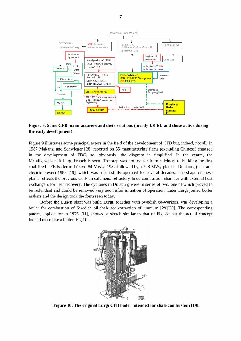
Figure 9. Some CFB manufacturers and their relations (mostly US-EU and those active during
the early development).
Figure 9 illustrates some principal actors in the field of the development of CFB but, indeed, not all: In
1987 Makansi and Schwieger [28] reported on 55 manufacturing firms (excluding Chinese) engaged
in the development of FBC, so, obviously, the diagram is simplified. In the centre, the
Metallgesellschaft/Lurgi branch is seen. The step was not too far from calciners to building the first
coal-fired CFB boiler in Lünen (84 MWth) 1982 followed by a 208 MWth plant in Duisburg (heat and
electric power) 1983 [19], which was successfully operated for several decades. The shape of these
plants reflects the previous work on calciners: refractory-lined combustion chamber with external heat
exchangers for heat recovery. The cyclones in Duisburg were in series of two, one of which proved to
be redundant and could be removed very soon after initiation of operation. Later Lurgi joined boiler
makers and the design took the form seen today.
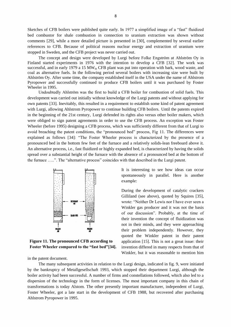
Before the Lünen plant was built, Lurgi, together with Swedish co-workers, was developing a
boiler for combustion of Swedish oil-shale for extraction of uranium [29][30]. The corresponding
patent, applied for in 1975 [31], showed a sketch similar to that of Fig. 8c but the actual concept
looked more like a boiler, Fig 10.
Figure 10. The original Lurgi CFB boiler intended for shale combustion [19].
1987, 1993 (Lurgi co-operation)
ABB (1989) Combustion
-
Engineering
US - UK 1970
- British coal, Renfrew (Babcock) Rivesville 1976
1996
1989
Metso
Kvaerner
Generator
Götaverken
Tampella
Petroleum & Chemical industry
BHEL
2000 Alstom
1996/97 Lurgi Lentjes Babcock 1993 2007 AE&E Lentjes 2011 Doosan Lentjes
FosterWheeler BFB 1978 -1990 Georgetown CFB 198 8 - 1995
Dongfang Harbin Shanghai Etc
A h lström 1979 CFB A h lstrom - Pyropower
Technology transfer 2003
Purchase 1995
License to Dongfang 1995
Winkler gasifier 1922 -
65
U SSR 1940 - -
60
China 1965 -
CFB Catcracker: Lewis Gilliland 1950
Metallgesellschaft ( Lurgi ) 1970s First CFB patents,
Lünen 1982 Keeler - Dorr Oliver
Valmet
Lurgi patent agreement
Lurgi patent agreement
2003 Envirotherm
8
Sketches of CFB boilers were published quite early. In 1977 a simplified image of a “fast” fluidized
bed combustor for shale combustion in connection to uranium extraction was shown without
comments [29], while a more detailed picture is presented in [30], complemented by several earlier
references to CFB. Because of political reasons nuclear energy and extraction of uranium were
stopped in Sweden, and the CFB project was never carried out.
The concept and design were developed by Lurgi before Folke Engström at Ahlström Oy in
Finland started experiments in 1976 with the intention to develop a CFB [32]. The work was
successful, and in early 1979 a 15 MWth CFB plant was put into operation with bark, wood waste, and
coal as alternative fuels. In the following period several boilers with increasing size were built by
Ahlström Oy. After some time, the company established itself in the USA under the name of Ahlstrom
Pyropower and successfully continued to produce CFB boilers until it was purchased by Foster
Wheeler in 1995.
Undoubtedly Ahlström was the first to build a CFB boiler for combustion of solid fuels. This
development was carried out initially without knowledge of the Lurgi patents and without applying for
own patents [33]. Inevitably, this resulted in a requirement to establish some kind of patent agreement
with Lurgi, allowing Ahlstrom Pyropower to continue building CFB boilers. Until the patents expired
in the beginning of the 21st century, Lurgi defended its rights also versus other boiler makers, which
were obliged to sign patent agreements in order to use the CFB process. An exception was Foster
Wheeler (before 1995) designing a CFB process, which was sufficiently different from that of Lurgi to
avoid breaching the patent conditions, the “pronounced bed” process, Fig 11. The differences were
explained as follows [34]: “The Foster Wheeler process is characterized by the presence of a
pronounced bed in the bottom few feet of the furnace and a relatively solids-lean freeboard above it.
An alternative process, i.e., fast fluidized or highly expanded bed, is characterized by having the solids
spread over a substantial height of the furnace with the absence of a pronounced bed at the bottom of
the furnace …..”. The “alternative process” coincides with that described in the Lurgi patent.
It is interesting to see how ideas can occur
spontaneously in parallel. Here is another
example:
During the development of catalytic crackers
Gilliland (see above), quoted by Squires [35],
wrote: “Neither Dr Lewis nor I have ever seen a
Winkler gas producer and it was not the basis
of our discussion”. Probably, at the time of
their invention the concept of fluidization was
not in their minds, and they were approaching
their problem independently. However, they
quoted the Winkler patent in their patent
application [15]. This is not a great issue: their
invention differed in many respects from that of
Winkler, but it was reasonable to mention him
in the patent document.
The many subsequent activities in relation to the Lurgi design, indicated in fig. 9, were initiated
by the bankruptcy of Metallgesellschaft 1993, which stopped their department Lurgi, although the
boiler activity had been successful. A number of firms and constellations followed, which also led to a
dispersion of the technology in the form of licenses. The most important company in this chain of
transformations is today Alstom. The other presently important manufacturer, independent of Lurgi,
Foster Wheeler, got a late start in the development of CFB 1988, but recovered after purchasing
Ahlstrom Pyropower in 1995.
Figure 11. The pronounced CFB according to
Foster Wheeler compared to the “fast bed”[34].

9
To the left on fig. 9, a great number of firms are seen, which converged into Valmet, another
Finnish company, after mergers and commercial transformations. The Chinese development, seen on
the right-hand side of the diagram, accelerated, especially after the technology transfer agreement with
Alstom 2003 that resulted in the 300 MWe plant in Baima, which was followed by an “explosion” of
new large-scale Chinese plants. At present, the largest boiler in the world, 600 MWe, designed by
Dongfang [36], has been taken into operation in China. The Chinese development, including Chinese
research related to boilers, has recently been described by Yue [37].
3.3.1 Resulting CFB designs
The predominant designs of CFB boilers, after gradual development, converge into rather
common features, irrespective of manufacturer: 1) the size of the air distributor at the furnace bottom
is about half of the cross section of the upper part, an effect of the inclined front and rear walls. About
half of the air is added through the bottom and the rest at one or two levels a few meters above the
bottom. The fuel is added in various points along the tapered walls and sometimes also in the return
ducts of bed material from the cyclones with one feed point per 20 to 30 m2 furnace cross-sectional
area for large boilers (To be compared with one feed point per m2 which was the recommendation for
coal-fired BFB). The arrangement with tapered walls reduces the consumption of electric power
compared to a design having straight vertical walls. It also improves mixing of fuel and air across the
cross section of the furnace; 2) The width of the furnace is limited to less than 10 m by the penetration
of the secondary-air jets and the spread of the fuel, clearly seen in larger boilers where the furnace
cross-section is given a rectangular shape; 3) A cyclone is the most efficient form of particle separator,
and CFB boilers have cyclones for particle recirculation, with a few notable exceptions, for instance
Babcock&Wilcox’ U-beam separator [38]. The cyclone is a centrifugal separator and its efficiency is
inversely proportional to its radius. Therefore, and for space reasons, large CFB boilers have several
cyclones. There are two options: cold or hot cyclones. The cold cyclones are connected to the steam-
water system of the boiler and are steam or water cooled. The hot cyclones are simply refractory
structures connected to the furnace through thermal expansion compensators; 4) Internal heat transfer
surfaces are wing walls located in the upper part of the furnace or internal walls extending from
bottom to top. In very large boilers external heat exchangers of some kind may be used; 5) In the
largest boilers built recently, the steam data are increased to the supercritical range, important for the
efficiency of electricity production but not significantly affecting the combustion side of the boiler.
Scale-up in size is an important trend during recent years. Originally, the membrane-tube walls
of the furnace served as the only heat-transfer surface, but during scaling up to larger size >50 MWth,
the wall surface area is insufficient, despite the fact that for large boilers the furnace is made as tall as
is considered reasonable, a maximum height around 50 m, fig. 12. Above that height, the particle
concentration has declined too much, and it may be difficult to maintain the bed temperature and the
heat transfer in the uppermost parts. To extend the heat-transfer area, internal surfaces (wing walls,
division walls etc.) are introduced, located in parallel to the particle flow. Finally, in large plant the
return flow of hot particles from the separator is used for heat transfer, as shown in fig. 13, either
through heat exchangers included in the loop seal (cf. fig. 8a and 8b) or in external heat exchangers
(cf. fig. 8c). Figure 13 indicates that designers prefer to use the more protected region in the return
loop, even though the capacity of a loop-seal heat-exchanger is limited. In fig. 12b it is shown how a
600 MW boiler could be formed from two 300 MW boilers. Among several minor adjustments
needed, the more limited space for wing walls in the large furnace, surrounded by cyclones, has to be
compensated by additional internal vertical heat-transfer panels and external heat exchangers (in
separate arrangement like in fig. 13a or in loop seals like in fig. 13b or c). The common wall may be
replaced by a dedicated internal tube-wall.

10
a) b) c)
Figure 13. Examples of external or loop seal heat exchangers from various manufacturers, a)
Alstom; b) Foster Wheeler; c) Valmet.
4. Development trends
Just like FBC was once introduced to the Western countries because of its anticipated
advantages with respect to low emissions of pollutants, the recent development trends utilize the
advantages of fluidized bed for devices aiming at CO2 reduction. These new development trends can
be divided into single-reactor systems (oxy-fuel combustion) and dual-reactor systems (chemical-
looping combustion, calcium looping, and several other systems consisting of two reactors). Dual
reactor systems have been used in the petroleum industry for a century. For gasification of biomass
and waste it was first introduced in the beginning of the 1970s in Kunii’s Pyrox plant [39] (see fig. 1),
consisting of two coupled fluidized beds. In the recent developments, this principle is employed both
for coal and for biomass gasification pilot plant. Below, some proposals for CO2 reduction and
biomass gasification will be described briefly. So far no large-scale plant for CO2 reduction has been
built.
4.1 Oxy-fuel combustion
4.1.1 Conventional CFB designs fed with oxygen, single FB system
An oxy-fuel CFB is a regular FBC
boiler supplied with pure oxygen instead of
air to produce CO2 in the flue gas, not being
diluted by nitrogen. To replace the nitrogen
and to moderate the O2 concentration, a
certain amount of the flue gas is recirculated
either as dry gas (CO2) or as wet gas
(CO2+H2O), as
seen in fig. 14.
Figure 12 Scale-up from a 300 MWe boiler with three cyclones (left) to a hypothetical 600
MWe plant (right), formed by the addition of two 300 MWe furnaces.
Figure 14. Oxygen supply to a CFB furnace
from an air separation unit. The flue gas can
be cleaned and dried before recirculation.
BoilerFlue gas cleaning
CondensationCO2
treatement
Steamcycle
Air separation
Air Nitrogen
CO2
Rest gases
Electric power
O2
H2O
Wet
Gas recirculation
DryDirty
30
40
8
300 MW 600 MW
50
16
30

11
The application for CO2 capture may have two forms: 1) the ”CO2-capture-ready” concept,
which is similar to present air-fired CFB boilers prepared for CO2 capture, if demanded; 2) “new
design” where the oxygen concentration is chosen as high as possible in a new boiler. The CO2-
capture-ready design replaces N2 with CO2, maintaining the design of the air-fired boiler with the same
bed and entrance temperatures Tbed and Tin. Also excess oxygen and fluidization velocity are kept
unchanged at given power and furnace dimensions. To fulfill the heat balance, the gas flow g times the
specific heat cp has to be identical in the air-fired (af) and CO2 circulation (co2) cases
(Tbed-Tin)(gcpgas)af=(Tbed-Tin)(gcpgas)co2. (1)
In the dry circulation case cpaf=1.098 and cpco2=1.090 kJ/kgK, that is, they are almost equal. The
gas flows in the air and CO2 circulation cases should then also be about equal, gaf≈gco2, which is
achieved by the recirculation of flue gas. To maintain the heat balance in the air-fired case a mass
concentration of oxygen of around 30% in the inlet gas is required, somewhat depending on the excess
oxygen chosen [40]. In order to keep the oxygen excess in the furnace similar to that of the air-fired
case, the excess oxygen supplied can be smaller than in the air case [40], because the circulated
oxygen helps maintaining a desired level in the furnace.
In contrast to an oxy-fired pulverized fuel boiler, in a CFB of the CO2-ready case there is an
additional criterion to be fulfilled: the fluidization velocity should be maintained constant. This,
however, is related to the volume flow and contradicts the heat balance criterion eq. (1), which is
based on mass flow: both cannot be fulfilled. The impact is not very large and the remedy is to relax
somewhat the strict equalities between temperatures and oxygen supply declared above.
The new-design case is straight-forward: for a given power most parameters are chosen similar
to conventional data except the excess oxygen, which can be lower than in air combustion for the
reason just mentioned. The amount of gas recirculated at a given bed temperature and fluidization
velocity depends on the chosen oxygen concentration in the input gas. The higher the oxygen
concentration, the less nitrogen has to be replaced by flue-gas recirculation: the total gas flow will be
smaller, and to attain the given fluidization velocity the cross-section of the furnace should be made
smaller, as seen in fig. 15 where an oxygen concentration of 60% gives half the furnace volume of a
corresponding air-fired boiler based on gross power (power consumption for air separation and CO2
compression for disposal have not been included). There will be less space for heat transfer surfaces,
and external heat exchangers may be necessary.
The decisive factor, so far not
well known, is the rate of particle
circulation to transport the particles
(heat) to the external heat exchangers.
In the literature there are few data on
the rate of particle circulation in boilers,
and those available are quite divergent,
ranging from 5-10 [41] to 30-40 [42]
for boilers of the kind treated here.
4.1.2 Chemical looping combustion
(CLC), dual FB system
In CLC, the drawback of the
above type of oxy-fuel CFB, the air-
separation unit, is absent. Instead, metal particles are oxidized in an air reactor (a CFB unit) and
transported to another FB reactor where the particles are reduced by reacting the fuel. This oxy-fuel
30
40
8 7
50
14
Figure 15. Comparison between air (left) and oxy-fired
(right) 300 MWe CFB @ 60%O2; Wall surfaces 240 m2
vs. 96 m2.The dimensions are taken from a typical air-
fired 300 MWe CFB boiler and the height of the oxy-
fuel boiler is extended as much as reasonable [40].

12
boiler, seen in fig. 16, belongs to the dual-reactor group consisting of an “air reactor” where oxidation
takes place and a “fuel reactor” where the oxygen brought by the oxidized particles is consumed by the
fuel. The present status of this method has been thoroughly reviewed [43, 44].
Heat removal
H2O, CO2,
Flue gas,N2, O2
Figure 16. CFB reactor system
for gaseous fuel, 1) air reactor, 2)
cyclone, 3) fuel reactor 4) loop
seals. In designs with solid fuel
the fuel reactor is a CFB
fluidized by added steam or by
steam/CO2 from the off gas.
Figure 17. Three cases of reaction in the fuel
reactor. (Right) A gaseous fuel reacts with a metal
oxide particle. (Center) A solid fuel particle is
gasified and then the gases react with the metal
oxide particle (MeO). (Left) A metal oxide particle
releases oxygen and enhances thereby the reaction.
Modified from [46] Modified from [45].
CO2 in the off-gas from the “fuel reactor” is free from nitrogen because the oxidation of the
metal powder in the air reactor by air leaves the nitrogen in the flue gases from that reactor. The metal,
now in the form of an oxide, is transported to the fuel reactor where it is reduced by the fuel, which
“burns”, yielding the gaseous combustion products H2O and CO2 in the off-gas to be treated for CO2
deposition. The ashes are removed, and the metal is returned to the air reactor for renewed oxidation.
With most oxygen carriers, the fuel energy is released during the oxidation, and the air reactor serves
as a boiler absorbing reaction energy and providing sensible heat to the fuel reactor by the oxygen
carriers. The total heat release is the same as in conventional combustion.
There are three major paths of reaction in the fuel reactor, as illustrated in fig. 17. The
application with gas as a fuel is simpler than with solid fuels. The fuel gas, serves as a fluidization
medium, and reacts directly with the metal oxide. The stoichiometric air-fuel volume ratio indicates
that the air volume is much larger than the fuel volume, and the CFB air-reactor could be coupled to a
BFB fuel-reactor. The conversion of solid fuels (particularly the char part) is more complicated. Solid-
solid reactions are out of question. So, the char has to be gasified by steam and/or CO2, which also
serve as the fluidization medium. Gasification is a slow process at the temperature concerned, but
enhancement is possible by the release of oxygen from some types of oxygen carrier for
thermodynamic reasons, while moving from the oxidizing conditions in the air reactor to the reducing
conditions in the fuel reactor. The oxygen released reacts readily with the fuel. Such a process is called
CLOU [47]. Other enhancement of a catalytic nature has been observed for some oxygen carriers [48].
Furthermore, the rate of gasification tends not to be inhibited by H2 and CO as usual in gasifiers, since
these gases are consumed by the oxygen carriers.
Preferably also the fuel reactor should be a circulating bed, because the fuel’s volatiles in
particular tend to react above the surface region of a BFB, and the contact with the oxygen carriers is
limited while the combustible gases ascend in the freeboard. In the circulating bed the oxygen carriers
are present in the entire reactor, although it is desired that the solids density be enhanced in the upper
part of the riser [49].
There are a number of complications that have to be solved by additional measures. The most
important ones are: 1) The ashes of solid fuels have to be separated from the oxygen carriers. Such a
FuelMeO
MeO
Moisture H2O, CO2
H2O, CO2 Volatiles
CO, H2
CH4
CH4H2O
Solid fuel Gaseous fuelProcesses in the fuel reactor
H2O
Fuel
MeO
Moisture
Volatiles
CO, H2
H2O
H2O
O2
CLOUInternal
gasification
H2O, CO2

13
separation process is not perfect, and therefore only cheap oxygen carriers, which can be wasted to
some extent, should be used; 2) In any case, the bed material (the oxygen carrier) contains ashes and
unburnt char, which has to be prevented from returning together with the metal particles into the air
reactor. Some burn-out device might be needed in between the two reactors; 3) Unburnt gases and
some char may escape with the CO2 from the fuel reactor, but in a CFB this amount can probably be
reduced to a low level.
On the whole, CLC is a promising technology, if the complications mentioned do not seriously
impede the process, and high combustion efficiency can be attained also with solid fuel. Although it
has not yet reached the pilot plant scale, one can imagine how a power plant using this technology
would look like: in Ref. [50] a tentative design and cost analysis is carried out.
4.2 CO2 removal from flue gases (Post combustion CO2 capture), dual FB systems
4.2.1 High-temperature systems (Calcium looping)
Calcium looping is a post-combustion CO2 capture process consisting of two coupled fluidized-
bed reactors, as suggested by Shimizu et al. [51]. Overviews of this method have been presented in
[52, 53]. The CO2 contained in the flue gas from any type of boiler is absorbed by CaO converted to
CaCO3 in a CFB reactor (the “carbonator”), fluidized by the same flue gas. The CaO needed is
produced from added limestone, CaCO3, and recycled material from the carbonator to another FB
reactor (the “calciner”) while CO2 is released for deposition. From there the CaO produced is returned
Figure 18. Equilibrium regions of calcination and carbonation in respective reactor,
shown as CO2 concentration vs. temperature.
again to the carbonator. The corresponding reactions take place when temperature and pressure in each
reactor are within the ranges of the respective chemical equilibria, as shown on fig. 18.
This flue-gas treatment method appears attractive because limestone is readily available in many
locations, and presently a great deal of research has been carried out to analyze this process, which is
an alternative to amine scrubbing to remove CO2 from flue gas. However, there are several severe
limitations: a) the absorption capacity of limestone decays rapidly after some cycles, although this can
be compensated for by allowing a sufficiently high circulation rate [54] and addition of make-up
limestone; b) the size of the equipment is large. Flue gases at 650 oC, which is a typical carbonator
temperature, have a considerable volume. Ströle et al. [55] estimated the cross section of the
carbonator to be about 400 m2
for a 1000 MWe power plant, despite rather favorable assumptions
(45.6% net efficiency of power production and 6 m/s fluidization velocity); c) the calcination reaction
is endothermal (178 kJ/kmol) and heat has to be supplied to the calciner by combustion, which
converts the calciner into a coal-fired oxy-fuel combustor (but not a to boiler, because the heat

14
produced is absorbed by the reactions), operating at a bed temperature of 900 oC. An air-separation
unit is required together with CO2 recirculation, just as has been described above for the oxy-fuel CFB
process and it is necessary to increase the plant capacity by 50% of the original power plant [55] and;
d) char contained in the bed material is transported back into the carbonator with the recirculating bed
material, which reduces the efficiency of the CO2 capture and may cause incomplete combustion.
In order to appreciate the disadvantages mentioned, one has to compare with alternative post-
combustion solutions, such as amine scrubbing by liquid amines. That method also requires equipment
of huge dimensions, and it has a considerable energy demand. The essential comparative advantage of
calcium looping is that the energy released from the exothermic carbonation is at sufficiently high
temperature level to be integrated in the power cycle, whereas the energy from amine scrubbing is
released at a low temperature level, making it difficult to find a use for this heat. CO2 avoidance costs
for calcium looping are estimated as lower than those of amine scrubbing [55].
4.2.2 Low-temperature systems
4.2.2.1 Dry alkali systems
In this proposed process, an alkali compound M (potassium or sodium) reacts in a carbonizer
with the CO2 of the wet flue gas from a boiler according to,
M2CO3+H2O+CO2=2MHCO3 (2)
The bicarbonate produced can be regenerated in a regeneration reactor, fig. 19,
The M2CO3 is then recirculated back to
the carbonizer. A description has been given
in [56]. There are some similarities with
calcium looping, but here the process goes
between an exothermic reaction below 100 oC,
but above the water dew-point, and an
endothermic decarbonization reaction at a
temperature of 120 to 200 oC higher. The
temperature level of the flue gas yields a gas
volume, which is about half of that of the
calcium looping process, but the heat
involved in the process is at low temperature
where excess heat is difficult to use.
4.2.2.2 Amine capture of CO2.
To improve CO2 capture by amines, sorbents are prepared by impregnation of solid carrier-
particles with amines. These particles are used in a CO2 removal reactor exposed to the cold-end flue
gases and then regenerated in a parallel reactor similar to the previously described arrangement of
calcium and alkali looping. An example of a publication dealing with the topic is Ref. [57].
4.3 Indirect gasification of biomass in dual FB systems
The gasification application with two reactors is called “indirect” in contrast to the Winkler type
of “direct” gasification. The heat necessary for gasification is produced by separate combustion in one
of the two reactors (the combustor) and transported with the bed material to the other reactor (the
2MHCO3=M2CO3+CO2+H2O (3)
Carbonizer
DecarbonizerConden-
ser
Cleaned gas from boiler
CO2-free gas to stack
CO2
Water out
Figure 19. Layout of an alkali CO2 capture system
in the cold flue-gas end of a power plant.

15
gasifier). The flue gas is emitted from the combustor and will not dilute the product gas from the
gasifier, which then attains a high heating value without using pure oxygen as would be necessary for
the corresponding purpose in a direct gasifier. Biomass and many wastes consist mostly of volatiles,
and in such cases pyrolysis of the fuel is a sufficient process in the gasification reactor, while the char
is needed in the combustion reactor to produce heat. Imbalance between available char and the fuel to
be burnt may require enhancement of gasification or additional fuel feed to the combustor. The
reasonably high heating value of the product gas (no nitrogen) is an advantage, while the method
shares its disadvantage with most other biomass and waste gasifiers: production of tars requires
cleaning, depending on the intended use of the product gas. The Güssing gasifier in Austria [58] is an
example of this type, which has succeeded to be introduced commercially in several places, for
instance, in the 20 MWfuel demonstration plant in Göteborg [59], intended for methane production
from biomass.
5. Conclusions
FBC is now a mature technology, but it is still greatly based on empirical knowledge, and new
applications: scale-up, load following, and increased efficiency would benefit from additional and
improved basic knowledge.
CO2 removal is the most important challenge for further development. Several routes are
proposed using FB both in single and dual reactor systems: oxy-combustion, chemical looping
combustion, calcium cycling, alkali cycling, and amine absorption with solid sorbents. The research is
still on the laboratory scale. Pilot scale plants have not yet been built, but would greatly accelerate
development.
Fluidized bed for conversion of biomass and wastes is being gradually improved. Combustion is
established, while gasification is fighting with economic obstacles.
6. Acknowledgement
This is an extended version of a presentation given at the 22nd International Fluidized Bed
Conversion Conference 2015.
References
[1] Winkler, F., (IG Farbenindustrie AG), Process for production of water gas, Patentschrift Nr
437970 (1922).
[2] Lambertz, J., Ewers, J., Clean coal Power, the answer of the power technology to the challenge
from the climate protection, VGB PowerTech, 5 (2006).
[3] Honkola, T., Industrial gasification demonstration plants by Metso, Finnish–Swedish Flame
days, Jyväskylä, 2013.
[4] Cemenenko, H.A., Cidelkovski, L.H., Particularities and experiences from the application of
fluidized bed furnaces (In Russian), Teploenergetika No 3, (1954), pp. 17-21.
[5] Cemenenko, H.A., Shurygin, A.P., Cidelkovski, L.H., Getting aquainted with furnaces with
fluidized bed (In Russian), Izvestia Vyshich Uchebnich Zavedenii Energetika, No 11 (1962), pp.
58-65.
[6] Zhang, X.Y., The progress of FBC boilers in People’s republic of China, 6th Int. Conf. on FBC,
US DoE, CONF-800428-Vol.1, 1980, pp.36-40.
[7] Gamble, R.L., Operation of the Georgetown University Fluidized Bed Steam Generator, 6th Int.
Conf. on FBC, US DoE, CONF-800428-Vol.1, 1980, pp. 307-316.

16
[8] Ehrlich, S., History of the development of the fluidized-bed boiler, Proc. of the 4th Int. Conf. on
FBC, ERDA, CONF-751213, Washington, pp. 15-20 (1975).
[9] Oka, S.N., Fluidized Bed Combustion, Chapter 5, Marcel Dekker Inc., 2004, ISBN:0-8247-
4699-6.
[10] Leckner, B., Optimization of emissions from fluidized bed boilers, Int. J. Energy Res., 6 (1992),
pp. 351-363
[11] Broadfield, B., Lipari, P.F., Slone, R.S., Engineering studies of atmospheric FBC electric power
plants in the USA, VDI Berichte Nr 322 (1978).
[12] Leckner, B., Atmospheric (non-circulating) fluidized bed combustion, Chapter 14 in (Ed. F.
Scala). Fluidized-bed technologies for near-zero emission combustion and gasification, 2013,
Woodhead Publishing Ltd., ISBN:0 85709 541 2.
[13] European Commission. Directive 2000/76/EC on the incineration of waste, Official Journal of
the European Communities L 332/91, 28.12.2000.
[14] Hoy, H.R., Roberts, A.G., Stantan, J.E., Chapter 1, Introduction, in: Pressurized Fluidized Bed
Combustion (Eds: M., Alvarez Cuenca, E.J., Anthony) 1995, ISBN: 978-94-010-4271-0.
[15] Lewis, W.K., Gilliland, E.R., (Standard Oil Dev Co), Conversion of hydrocarbons with
suspended catalyst, US Patent 2,498,088, (Patented 1950, original application 1940).
[16] Lewis, W.K., (Standard Oil Dev.Co), Reaction between solids and gases, US Patent 2,343,780,
(Patented March, 1944, application August 1941).
[17] The Fluid Bed Reactor, The Office of Communications, American Chemical Society, 1998.
[18] Schytil, F., Calcination of aluminium hydrooxide, Auslegeschrift 1146041 (1960-1963).
[19] Reh, L., The circulating fluid bed reactor—its main features and applications, Chemical
Engineering and Processing: Process Intensification, 20 (1986), pp. 117-127.
[20] Stahl, G., Becuwe, J., (Rhône Progil), Procedure and apparatus for combustion of household and
industrial waste (In French), Patent FR2 209 074 (1972).
[21] Yerushalmi, J., Erlich, S., Maagoul, M., (EPRI), Apparatus and method for combusting
carbonaceous fuels employing in tandem a fast bed boiler and a slow boiler, US Patent 4103646
(1978).
[22] Yerushalmi, J., Turner, D.H., Squires, A.M., The fast fluidized bed, Ind. Eng. Chem. Proc.
Design Dev., 15 (1976), pp. 47-53.
[23] Reh, L., Fluidized bed processing, Chem. Eng. Progr., 67 (1971), pp. 58-63.
[24] Reh, L., Hirsch M, Plass L, (Metallgesellschaft AG), Method and apparatus for carrying out an
exothermic process, US Patent 4111158 (1978).
[25] Reh, L., Hirsch, M., Collin, H., Flink, S.N., (Metallgesellschaft AG), Process for burning
carbonaceous materials, US Patent 4165717 (1979).
[26] Kwauk, M., Fluidization, idealized and bubbleless, with applications, Science Press, Beijing,
1992.
[27] Hyppänen, T., Kuivalainen, R., Ollila, H., (Ahlström OY), Centrifugal separator, Patent
EP0481438 (A2) (1992).
[28] Makansi, J., Schwieger, R., Fluidized-bed boilers, Power, May 1987, pp. S1-S16.
[29] Oscarsson, B., Sjöberg, K., All the valuable components of the Ranstad shale are to be
recovered (In Swedish), Teknisk Tidskrift, 14 (1977), pp. 26-29.
[30] Reh, L., Plass, L., Hirsch, M., Utilization of energy and raw materials content of minerals
containing carbon (In German), VDI-Berichte Nr. 322, 1978.
[31] Reh, L., Hirsch, M., Collin P.H., Flink, S.N., Process burning materials containing carbon (In
German), German Patent No 25395469 (1975).
[32] Engström, F., Development and commercial operation of a circulating fluidized bed combustion
system, 6th Int. Conf. on FBC, Atlanta 1980, US DOE.
[33] Engström, F., Personal communication.

17
[34] Abdulally, I., Parham, D., Cox, J., Foster Wheeler’s answer to meeting the challenge: large
scale CFB unit design for the eclectric utility market, The 5th Int. Power Generation Exhibition
& Conf., Orlando Fl, 1992.
[35] Squires, A.M., The story of fluid catalytic cracking: the first circulating fluidized bed, in
Circulating Fluidized Bed Technology (Ed. P Basu), Pergamon Press, 1986.
[36] Li, Y., Nie, L., Hu. X.K., et al., Structure and performance of a 600 MWe supercritical CFB
boiler with water cooled panels, 20th Int. Conf. on FBC, Xian, (Eds. G. Yue, et al.), 2009, pp.
132-136.
[37] Yue, G., The contribution on CFB combustion theory by China, 22nd
Int. Conf. on FBC (Eds. D.
Bankiewicz, M. Mäkinen, P. Yrjas), Turku 2015, pp. 12-22.
[38] Babcock&Wilcox Power Generation Group, Internal Recirculation Circulating Fluidized-Bed
Boilers, Brochure (2006), http://www.babcock.com/library/documents/e1013148.pdf
[39] Kunii, D., Chemical reaction engineering and research and development of gas solid systems,
Chem. Eng. Sci., 35 (1980), pp. 1887-1911.
[40] Leckner, B., Gómez-Barea, A., Oxy-fuel combustion in circulating fluidized bed boilers, Appl.
Energy, 125 (2014), pp. 308–318.
[41] Yue, G., Lu, J., Zhang, H., et al., Design theory of circulating fluized bed boilers, 18th Int. Conf.
on FBC, Toronto, 2005.
[42] Wu, H., Zhang, M., Sun, Y., et al., Research on the heat transfer model of platen heating
surface of 300 MW circulating fluidized bed boilers, Powder Techn., 226 (2012), pp. 83–90.
[43] Lyngfelt, A., Chemical looping combustion, Chapter 20 in (Ed. F. Scala), 2013, Fluidized-bed
technologies for near-zero emission combustion and gasification, Woodhead Publishing Ltd.
ISBN:0 85709 541 2.
[44] Adánez, J., Abad, A., García-Labiano, F., et al., Progress in Chemical-Looping Combustion and
Reforming technologies, Progr. Energy Comb. Sci., 38 (2012), pp. 215–282.
[45] Lyngfelt, A., Leckner, B., Mattisson, T., A fluidized bed combustion process with inherent CO2
separation; application of chemical-looping combustion, Chem. Eng. Sci., 56 (2001), pp. 3101-
3113.
[46] Leckner, B., Zero emission coal technologies--a summary, Reunión del Grupo Español del
Carbón, 2007, Teruel, Spain.
[47] Mattisson, T., Lyngfelt, A., Leion, H., Chemical-looping with oxygen uncoupling for
combustion of solid fuels, Int. J. Greenhouse Gas Control, 3 (2009), pp. 11-9.
[48] Keller, M., Leion, H., Mattisson, T., Mechanisms of solid fuel conversion by chemical looping
combustion (CLC) using manganese ore: catalytic gasification by potassium compounds,
Energy Technol., 1 (2013), pp. 273-282.
[49] Pröll, T., Hofbauer, H., A dual fluidized bed system for chemical looping combustion of solid
fuels, AIChE Annual Meeting 2010, Salt Lake City USA.
[50] Lyngfelt, A., Leckner, B., A 1000 MWth boiler for chemical-looping combustion of solid
fuels—discussion of design and costs, Appl. Energy
http://dx.doi.org/10.1016/j.apenergy.2015.04.057 (In press).
[51] Shimizu, T., Hirama, T., Hosoda, H., et al., Twin bed reactor for removal of CO2 from
combustion processes, Inst. Chem. Engns., 77 (1999), pp. 62-68.
[52] Blamey, J., Anthony, E.J., Wang, J., Fennell, P.S., The calcium looping cycle for large-scale
CO2 capture, Progr. Energy and Combust. Sci., 36 (2010), pp. 260–279.
[53] Anthony, E.J., Ca looping technology: current status, developments and future directions,
Greenhouse Gases: Science and Technology, 1 (2011), pp. 36–47.
[54] Sánchez-Biezma, A., Ballesteros, J.C., Diaz, L., et al., Postcombustion CO2 capture with CaO.
Status of the technology and next steps towards large scale demonstration, Energy Procedia, 4
(2011), pp. 852-859.

18
[55] Ströhle, J., Galloy, A., Epple, B., Feasibility study on the carbonate looping process for post-
combustion CO2 capture from coal-fired plants, Energy Procedia, 1 (2009), pp. 1313-1320.
[56] Zhao, C., Chen, X., Anthony, E.J., et al., Capturing CO2 in flue gas from fossil fuel-fired power
plants using dry regenerable alkali metal-based sorbent, Progr. Energy Comb. Sci., 39 (2013).
pp. 515-534.
[57] Veneman, R., Li, Z.S., Hogendoorn, J.A., et al., Continuous CO2 capture in a circulating
fluidized bed using supported amine sorbents, Chem. Eng. J., 207-208 (2012), pp. 18-26.
[58] Hofbauer, H., Aichernig, C., Fluidized bed gasification based on steam: the Güssing example,
VDI Berichte, Issue 1891 (2005), pp. 197-211.
[59] Hedenskog, M., Gasification of forest residues in a large demonstration scale -- The GoBiGas-
project, International Seminar on Gasification 2014, The Swedish Gas Technology Center,
Malmö.