development platform for i.mx 6quad built to freescale ... · user manual v1.2 mcimx6q-sl:...
TRANSCRIPT
Development Platform for i.MX 6Quad
Built to Freescale SABRE Lite design
USER MANUAL v1.2 MCIMX6Q-SL: element14 development platform for i.MX 6Quad
Built to Freescale SABRE Lite design
2
Table of Contents
1 BOARD OVERVIEW ................................................................................................................................................................ 5
1.1 PRODUCT INTRODUCTION ..................................................................................................................................................... 5
1.2 FEATURES .......................................................................................................................................................................... 6
2 QUICK START GUIDE .............................................................................................................................................................. 8
2.1 UNPACKING THE KIT ............................................................................................................................................................ 8
2.2 WEB-BASED CONTENTS ....................................................................................................................................................... 8
2.3 SETTING UP THE SYSTEM ...................................................................................................................................................... 8
2.3.1 Insert MicroSD Card ................................................................................................................................................... 8
2.3.2 Connect RS-232 cable ................................................................................................................................................ 8
2.3.3 Connect USB OTG (optional) ...................................................................................................................................... 9
2.3.4 Connect the Power Supply ......................................................................................................................................... 9
3 HARDWARE DESCRIPTION ................................................................................................................................................... 10
3.1 PROCESSOR ..................................................................................................................................................................... 10
3.1.1 Core Features ........................................................................................................................................................... 10
3.1.2 External memory interfaces: .................................................................................................................................... 11
3.1.3 Interface to external devices .................................................................................................................................... 11
3.1.4 Advanced Power Management unit ........................................................................................................................ 12
3.1.5 Hardware Accelerators ............................................................................................................................................ 13
3.2 EXPANDED CHIP INTRODUCTION .......................................................................................................................................... 13
3.2.1 H5TQ2G63BFR-H9C ................................................................................................................................................. 13
3.2.2 SST25VF016B ........................................................................................................................................................... 13
3.2.3 KSZ9021RN .............................................................................................................................................................. 13
3.2.4 USB2513B-AEZG for USB 2.0 High Speed 3-Port Hub .............................................................................................. 14
3.2.5 SGTL5000 ................................................................................................................................................................. 14
3.2.6 ICL3232CVZ .............................................................................................................................................................. 14
3.2.7 TJA1040T ................................................................................................................................................................. 14
3.3 HARDWARE INTERFACE ...................................................................................................................................................... 15
3.3.1 Power Input Jack ...................................................................................................................................................... 15
3.3.2 SATA Power Interface ............................................................................................................................................... 15
3.3.3 SATA Data Interface ................................................................................................................................................. 16
3.3.4 CAN Interface ........................................................................................................................................................... 17
3.3.5 Parallel RGB Interface .............................................................................................................................................. 17
3.3.6 Audio Output Jack .................................................................................................................................................... 19
3.3.7 Microphone Input Jack ............................................................................................................................................ 20
3.3.8 Camera Interface ..................................................................................................................................................... 20
USER MANUAL v1.2 MCIMX6Q-SL: element14 development platform for i.MX 6Quad
Built to Freescale SABRE Lite design
3
3.3.9 RS232 Serial Port ..................................................................................................................................................... 22
3.3.10 RGMII LAN Interface ............................................................................................................................................ 22
3.3.11 USB Host Interface ............................................................................................................................................... 23
3.3.12 Micro USB Interface ............................................................................................................................................. 24
3.3.13 SD Card Interface ................................................................................................................................................. 25
3.3.14 JTAG Interface ...................................................................................................................................................... 25
3.3.15 Expansion Interface ............................................................................................................................................. 26
3.3.16 Boot Configuration Select .................................................................................................................................... 26
3.3.17 ANDROID KEYBOARD INTERFACE ........................................................................................................................ 27
3.3.18 LED ....................................................................................................................................................................... 28
3.3.19 Switch .................................................................................................................................................................. 28
3.3.20 TF/MMC Card Interface ....................................................................................................................................... 29
3.3.21 HDMI Interface .................................................................................................................................................... 29
3.3.22 LVDS Interface ...................................................................................................................................................... 30
3.3.23 MIPI Interface ...................................................................................................................................................... 31
3.3.24 PCIe Interface ...................................................................................................................................................... 32
4 SOFTWARE DESCRIPTION .................................................................................................................................................... 33
4.1 SOFTWARE OVERVIEW- LINUX ............................................................................................................................................. 33
4.1.1 System Development ............................................................................................................................................... 33
4.1.1.1 Preparing the Board .......................................................................................................................................................... 33
4.1.1.2 Booting your Board ............................................................................................................................................................ 34
4.1.1.3 Using the Demo ................................................................................................................................................................. 34
4.1.2 For More Information .............................................................................................................................................. 35
4.2 ANDROID ........................................................................................................................................................................ 37
4.2.1 Quick Guide ............................................................................................................................................................. 37
4.2.1.1 How to Boot the i.MX 6Dual/Quad SABRE-Lite Board ....................................................................................................... 37
4.2.1.2 Setup Terminal ................................................................................................................................................................... 38
4.2.2 Download Images .................................................................................................................................................... 39
4.2.2.1 System on TF card .............................................................................................................................................................. 39
4.2.2.2 System on NFS ................................................................................................................................................................... 43
4.2.3 Running the Image on the Target ............................................................................................................................ 44
4.2.3.1 Running the Image from MMC/SD ................................................................................................................................... 44
4.2.3.2 Running the image from NFS ............................................................................................................................................ 45
4.2.4 BSPs ........................................................................................................................................................................ 45
4.2.4.1 Introduction ....................................................................................................................................................................... 45
4.2.4.2 PC Setup ............................................................................................................................................................................ 45
4.2.4.3 Prebuilt image ................................................................................................................................................................... 46
4.2.4.4 Build Android for i.MX ..................................................................................................................................................... 46
5 APPENDIX ............................................................................................................................................................................ 49
USER MANUAL v1.2 MCIMX6Q-SL: element14 development platform for i.MX 6Quad
Built to Freescale SABRE Lite design
4
5.1 ESD PRECAUTIONS AND PROPER HANDLING PROCEDURES ........................................................................................... 49
LIST OF FIGURES
Figure 11 Functional Block Diagram of SABRE Lite Board ............................................................................................ 5
Figure 31 Block Diagram of i.MX 6Dual/6Quad .......................................................................................................... 11
Figure 32 SABRE Lite Board ........................................................................................................................................ 15
Figure 33 SATA Power Interface ................................................................................................................................. 15
Figure 34 SATA connector .......................................................................................................................................... 16
Figure 35 CAN Interface .............................................................................................................................................. 17
Figure 36 Parallel RGB Interface ................................................................................................................................. 17
Figure 37 Audio Output Jack ....................................................................................................................................... 19
Figure 38 MIC In Jack .................................................................................................................................................. 20
Figure 39 RS232 Serial Port ........................................................................................................................................ 22
Figure 310 RGMII LAN Interface ................................................................................................................................. 22
Figure 311 Micro USB Interface .................................................................................................................................. 24
Figure 312 TF/MMC Card Interface ............................................................................................................................ 29
LIST OF TABLES
Table 21 SABRE Lite Kit Contents ................................................................................................................................. 8
Table 31 Power Interface ........................................................................................................................................... 15
Table 32 SATA Power Interface .................................................................................................................................. 16
Table 33 SATA Connector ........................................................................................................................................... 16
Table 34 CAN Interface ............................................................................................................................................... 17
Table 35 Parallel RGB interface .................................................................................................................................. 18
Table 36 Audio Output Jack ........................................................................................................................................ 19
Table 37 MIC In Jack ................................................................................................................................................... 20
Table 38 Camera Interface ......................................................................................................................................... 20
Table 39 RS-232 Serial Port ........................................................................................................................................ 22
Table 310 RGMII LAN interface .................................................................................................................................. 23
Table 311 USB Host Interface ..................................................................................................................................... 23
Table 312 USB Host Interface ..................................................................................................................................... 24
Table 313 Micro USB Interface ................................................................................................................................... 24
Table 314 SD Card Interface ....................................................................................................................................... 25
Table 315 JTAG Interface ............................................................................................................................................ 25
Table 316 IIC expansion interface .............................................................................................................................. 26
Table 317 Boot Configuration Select .......................................................................................................................... 26
Table 318 ANDROID BUTTONS ................................................................................................................................... 27
Table 319 LED ............................................................................................................................................................. 28
Table 320 Reset Switch ............................................................................................................................................... 28
Table 321 Boot Switch ................................................................................................................................................ 28
Table 322 TF/MMC Card Interface ............................................................................................................................. 29
Table 323 HDMI Interface .......................................................................................................................................... 29
Table 324 LVDS Interface ............................................................................................................................................ 30
Table 325 MIPI Interface ............................................................................................................................................ 31
Table 326 PCIe Interface ............................................................................................................................................. 32
USER MANUAL v1.2 MCIMX6Q-SL: element14 development platform for i.MX 6Quad
Built to Freescale SABRE Lite design
5
1 Board Overview
1.1 Product Introduction
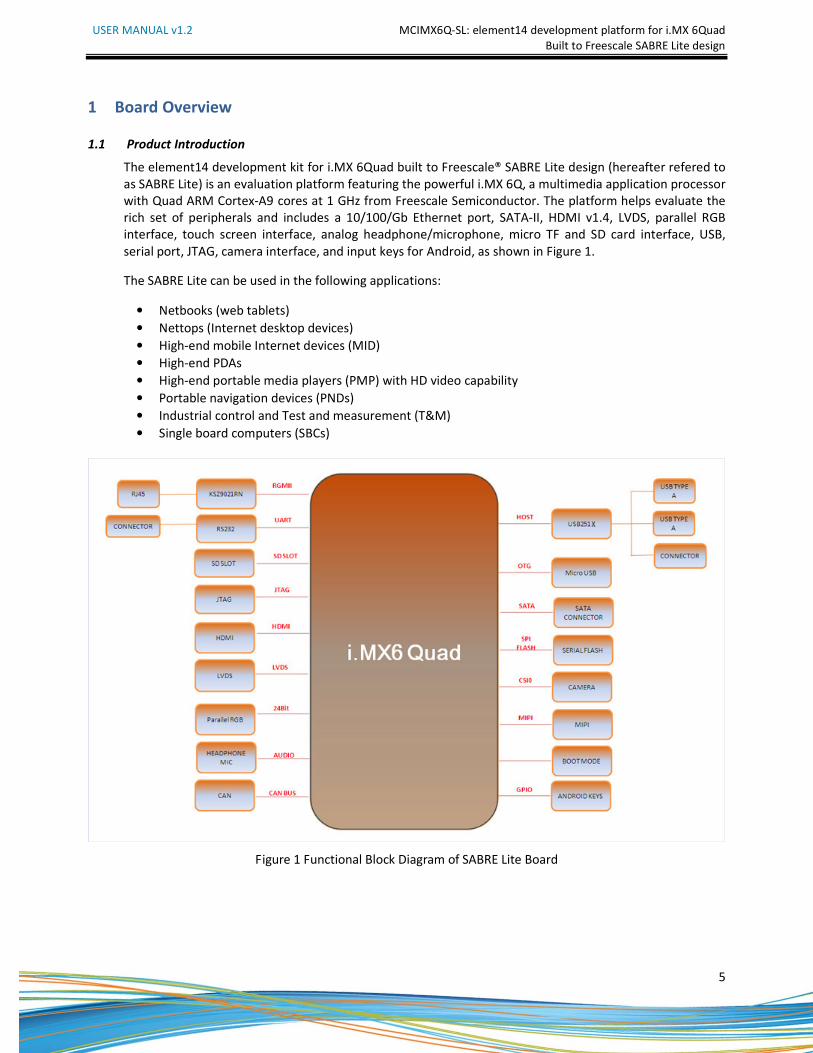
The element14 development kit for i.MX 6Quad built to Freescale® SABRE Lite design (hereafter refered to
as SABRE Lite) is an evaluation platform featuring the powerful i.MX 6Q, a multimedia application processor
with Quad ARM Cortex-A9 cores at 1 GHz from Freescale Semiconductor. The platform helps evaluate the
rich set of peripherals and includes a 10/100/Gb Ethernet port, SATA-II, HDMI v1.4, LVDS, parallel RGB
interface, touch screen interface, analog headphone/microphone, micro TF and SD card interface, USB,
serial port, JTAG, camera interface, and input keys for Android, as shown in Figure 1.
The SABRE Lite can be used in the following applications:
• Netbooks (web tablets)
• Nettops (Internet desktop devices)
• High-end mobile Internet devices (MID)
• High-end PDAs
• High-end portable media players (PMP) with HD video capability
• Portable navigation devices (PNDs)
• Industrial control and Test and measurement (T&M)
• Single board computers (SBCs)
Figure 1 Functional Block Diagram of SABRE Lite Board
USER MANUAL v1.2 MCIMX6Q-SL: element14 development platform for i.MX 6Quad
Built to Freescale SABRE Lite design
6
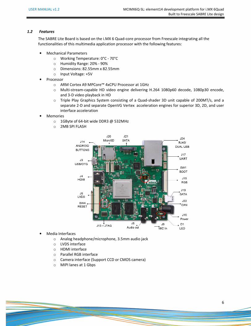
1.2 Features
The SABRE Lite Board is based on the i.MX 6 Quad-core processor from Freescale integrating all the
functionalities of this multimedia application processor with the following features:
• Mechanical Parameters
o Working Temperature: 0°C - 70°C
o Humidity Range: 20% - 90%
o Dimensions: 82.55mm x 82.55mm
o Input Voltage: +5V
• Processor
o ARM Cortex A9 MPCore™ 4xCPU Processor at 1GHz
o Multi-stream-capable HD video engine delivering H.264 1080p60 decode, 1080p30 encode,
and 3-D video playback in HD
o Triple Play Graphics System consisting of a Quad-shader 3D unit capable of 200MT/s, and a
separate 2-D and separate OpenVG Vertex acceleration engines for superior 3D, 2D, and user
interface acceleration
• Memories
o 1GByte of 64-bit wide DDR3 @ 532MHz
o 2MB SPI FLASH
• Media Interfaces
o Analog headphone/microphone, 3.5mm audio jack
o LVDS interface
o HDMI interface
o Parallel RGB interface
o Camera interface (Support CCD or CMOS camera)
o MIPI lanes at 1 Gbps
USER MANUAL v1.2 MCIMX6Q-SL: element14 development platform for i.MX 6Quad
Built to Freescale SABRE Lite design
7
• Data Transfer Interfaces
o Serial Ports
� UART1, 3 line serial port, RS232 Logic
� UART2, 3 line serial port, RS232 Logic
o USB Ports:
� USB2.0 OTG, micro USB, high-speed, 480Mbps
� Two USB2.0 HOST, Type A, high-speed, 480Mbps
� USB2.0 HOST, connector, high-speed, 480Mbps
o TF card interface
o SD card interface
o SATA II interface, 3.0 Gbps
o 10M/100M/Gb Ethernet Interface (RJ45 jack)
o 1 channel I2C interface
o 1 channel PCIE X1 interface
o CAN bus
• Input Interfaces
o Android keyboard interface
o 10-pin JTAG interface
o 2 bit DIP switch for boot mode selection
o Boot configuration interface
• Others
o Power LED
o DC Jack
o Reset button
USER MANUAL v1.2 MCIMX6Q-SL: element14 development platform for i.MX 6Quad
Built to Freescale SABRE Lite design
8
2 Quick Start Guide
This section describes how to use the SABRE Lite and associated components.
2.1 Unpacking the Kit
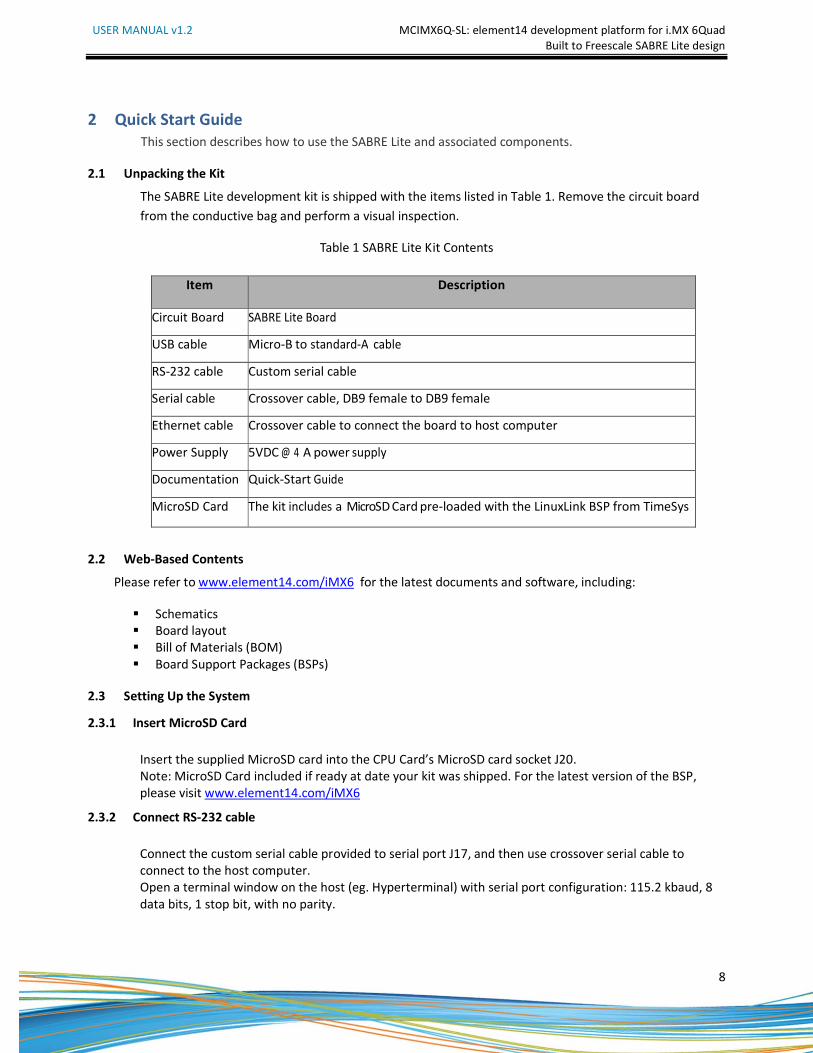
The SABRE Lite development kit is shipped with the items listed in Table 1. Remove the circuit board
from the conductive bag and perform a visual inspection.
Table 1 SABRE Lite Kit Contents
2.2 Web-Based Contents
Please refer to www.element14.com/iMX6 for the latest documents and software, including:
� Schematics
� Board layout
� Bill of Materials (BOM)
� Board Support Packages (BSPs)
2.3 Setting Up the System
2.3.1 Insert MicroSD Card
Insert the supplied MicroSD card into the CPU Card’s MicroSD card socket J20.
Note: MicroSD Card included if ready at date your kit was shipped. For the latest version of the BSP,
please visit www.element14.com/iMX6
2.3.2 Connect RS-232 cable
Connect the custom serial cable provided to serial port J17, and then use crossover serial cable to
connect to the host computer.
Open a terminal window on the host (eg. Hyperterminal) with serial port configuration: 115.2 kbaud, 8
data bits, 1 stop bit, with no parity.
Item Description
Circuit Board SABRE Lite Board
USB cable Micro-B to standard-A cable
RS-232 cable Custom serial cable
Serial cable Crossover cable, DB9 female to DB9 female
Ethernet cable Crossover cable to connect the board to host computer
Power Supply 5VDC @ 4 A power supply
Documentation Quick-Start Guide
MicroSD Card The kit includes a MicroSD Card pre-loaded with the LinuxLink BSP from TimeSys

USER MANUAL v1.2 MCIMX6Q-SL: element14 development platform for i.MX 6Quad
Built to Freescale SABRE Lite design
9
2.3.3 Connect USB OTG (optional)
Connect the cable from the kit to micro USB connector J3 on the board.
2.3.4 Connect the Power Supply
Plug in the 5VDC supply to power jack J10, the power LED (D1) should illuminate.
To reboot, press the reset button SW4
USER MANUAL v1.2 MCIMX6Q-SL: element14 development platform for i.MX 6Quad
Built to Freescale SABRE Lite design
10
3 Hardware Description
3.1 Processor
The i.MX 6Dual/6Quad processors represents Freescale Semiconductor’s latest achievement in integrated
multimedia applications processors, which are part of a growing family of multimedia-focused products that
offer high performance processing and are optimized for lowest power consumption.
The processor features Freescale’s advanced implementation of the quad ARM™ Cortex-A9 core, which
operates at speeds up to 1GHz. They include 2D and 3D graphics processors, 3D 1080p video processing, and
integrated power management. Each processor provides a 64-bit DDR3/LVDDR3-1066 memory interface and a
number of other interfaces for connecting peripherals, such as WLAN, Bluetooth™, GPS, hard drive, displays,
and camera sensors.
3.1.1 Core Features
The i.MX 6Dual/6Quad processors are based on the ARM Cortex A9 MPCore™ platform with the following
features:
• ARM Cortex A9 MPCore™ 4xCPU Processor (with TrustZone)
• The core configuration is symmetric, where each core includes:
o 32 KByte L1 Instruction Cache
o 32 KByte L1 Data Cache
o Private Timer and Watchdog
o Cortex-A9 NEON MPE (Media Processing Engine) Co-processor
• The ARM Cortex A9 MPCore™ complex includes:
o General Interrupt Controller (GIC) with 128 interrupt support
o Global Timer
o Snoop Control Unit (SCU)
o 1 MB unified I/D L2 cache, shared by two/four cores
o Two Master AXI (64-bit) bus interfaces output of L2 cache
o Target frequency of the core (including Neon and L1 cache) is:
o 1 GHz overdrive over the specified temperature rang
o 900 MHz non-overdrive over the specified temperature range
o NEON MPE coprocessor
o SIMD Media Processing Architecture
o NEON register file with 32x64bit general-purpose registers
o NEON Integer execute pipeline (ALU, Shift, MAC)
o NEON dual, single-precision floating point execute pipeline (FADD, FMUL)
o NEON load/store and permute pipeline
• The memory system consists of the following components:
o Level 1 Cache--32 KB Instruction, 32 KB Data cache per core
o Level 2 Cache--Unified instruction and data (1 MByte)
o On-Chip Memory:
o Boot ROM, including HAB (96 KB)
o Internal multimedia / shared,fast access RAM (OCRAM, 256 KB)
o Secure/non-secure RAM (16 KB)
USER MANUAL v1.2 MCIMX6Q-SL: element14 development platform for i.MX 6Quad
Built to Freescale SABRE Lite design
11
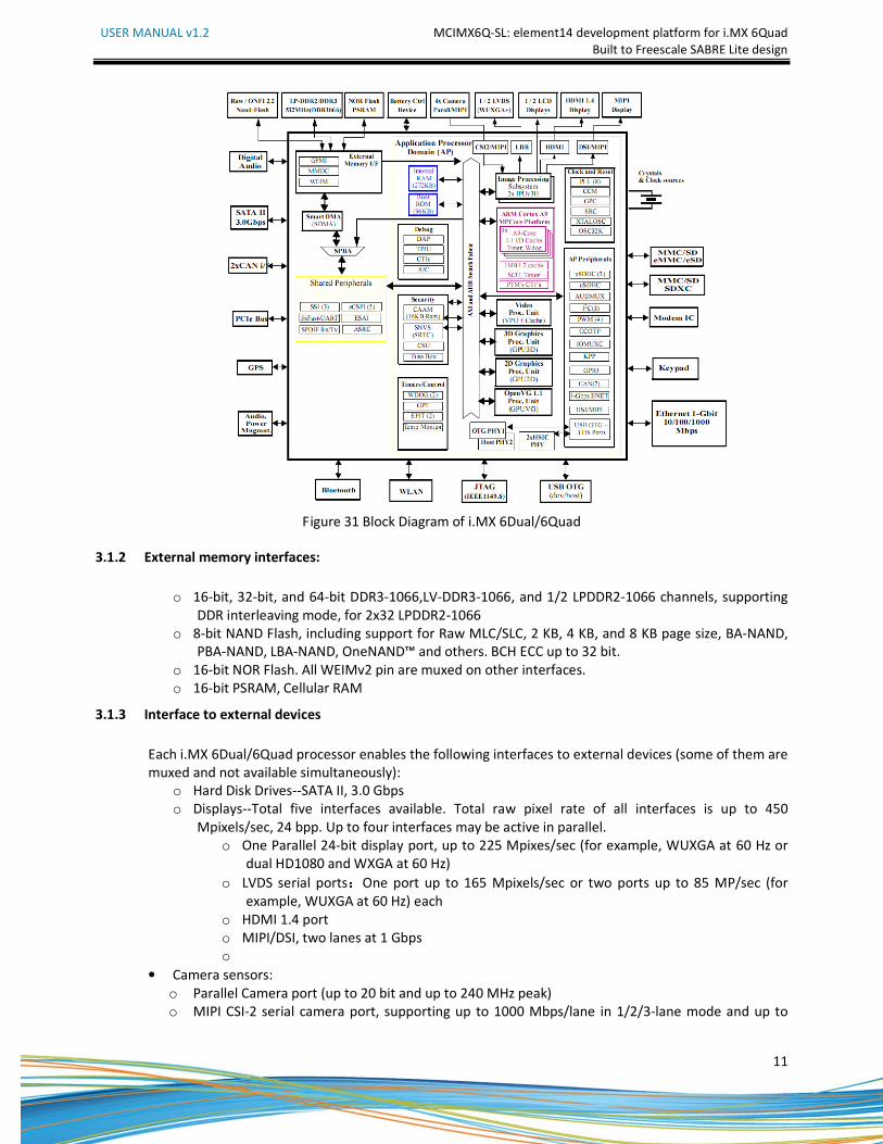
Figure 31 Block Diagram of i.MX 6Dual/6Quad
3.1.2 External memory interfaces:
o 16-bit, 32-bit, and 64-bit DDR3-1066,LV-DDR3-1066, and 1/2 LPDDR2-1066 channels, supporting
DDR interleaving mode, for 2x32 LPDDR2-1066
o 8-bit NAND Flash, including support for Raw MLC/SLC, 2 KB, 4 KB, and 8 KB page size, BA-NAND,
PBA-NAND, LBA-NAND, OneNAND™ and others. BCH ECC up to 32 bit.
o 16-bit NOR Flash. All WEIMv2 pin are muxed on other interfaces.
o 16-bit PSRAM, Cellular RAM
3.1.3 Interface to external devices
Each i.MX 6Dual/6Quad processor enables the following interfaces to external devices (some of them are
muxed and not available simultaneously):
o Hard Disk Drives--SATA II, 3.0 Gbps
o Displays--Total five interfaces available. Total raw pixel rate of all interfaces is up to 450
Mpixels/sec, 24 bpp. Up to four interfaces may be active in parallel.
o One Parallel 24-bit display port, up to 225 Mpixes/sec (for example, WUXGA at 60 Hz or
dual HD1080 and WXGA at 60 Hz)
o LVDS serial ports:One port up to 165 Mpixels/sec or two ports up to 85 MP/sec (for
example, WUXGA at 60 Hz) each
o HDMI 1.4 port
o MIPI/DSI, two lanes at 1 Gbps
o
• Camera sensors:
o Parallel Camera port (up to 20 bit and up to 240 MHz peak)
o MIPI CSI-2 serial camera port, supporting up to 1000 Mbps/lane in 1/2/3-lane mode and up to
USER MANUAL v1.2 MCIMX6Q-SL: element14 development platform for i.MX 6Quad
Built to Freescale SABRE Lite design
12
800 Mbps/lane in 4-lane mode. The CSI-2 Receiver core can manage one clock lane and up to four
data lanes. Each i.MX 6Dual/6Quad processor has four lanes.
• Expansion cards:
o Four MMC/SD/SDIO card ports all supporting:
o 1-bit or 4-bit transfer mode specifications for SD and SDIO cards up to UHS-I SDR-104 mode (104
MB/s max)
o 1-bit, 4-bit, or 8-bit transfer mode specifications for MMC cards up to 52 MHz in both SDR and
DDR modes (104 MB/s max)
• USB
o High Speed (HS) USB 2.0 OTG (Up to 480 Mbps), with integrated HS USB PHY
o Three USB 2.0 (480 Mbps) hosts
o One HS host with integrated High Speed PHY
o Two HS hosts with integrated HS-IC USB (High Speed Inter-Chip USB) PHY
• Expansion PCI Express port (PCIe) v2.0 one lane
o PCI Express (Gen 2.0) dual mode complex, supporting Root complex operations and Endpoint
operations. Uses x1 PHY configuration.
• Miscellaneous IPs and interfaces:
o Three I2S/SSI/AC97,up to 1.4 Mbps each
o Enhanced Serial Audio Interface ESAI), up to 1.4 Mbps per channel
o Five UARTs, up to 4.0 Mbps each
o Providing RS232 interface
o Supporting 9-bit RS485 multidrop mode
o One of the five UARTs (UART1) supports 8-wir while others four supports 4-wire. This is due to
the SoC IOMUX limitation, since all UART IPs are identical.
o Five eCSPI (Enhanced CSI), up to 52 Mbps each
o Three I2C, supporting 400 kbps
o Gigabit Ethernet Controller(IEEE1588 compliant), 10/100/1000 Mbps
o Four Pulse Width Modulators (PWM)
o System JTAG Controller (SJC)
o GPIO with interrupt capabilities
o 8x8 Key Pad Port (KPP)
o Sony Philips Digital Interface (SPDIF), Rx and Tx
o Two Controller Area Network (FlexCAN), 1 Mbps each
o Two Watchdog timers (WDOG)
o Audio MUX (AUDMUX)
3.1.4 Advanced Power Management unit
The i.MX 6Dual/6Quad processors integrate advanced power management unit and controllers:
• Provide PMU, including DCDC and LDO supplies, for on-chip resources
• Use Temperature Sensor for monitoring the die temperature
• Support DVFS techniques for low power modes
• Use SW State Retention and Power Gating for ARM and MPE
• Support various levels of system power modes
• Use flexible clock gating control scheme
USER MANUAL v1.2 MCIMX6Q-SL: element14 development platform for i.MX 6Quad
Built to Freescale SABRE Lite design
13
3.1.5 Hardware Accelerators
The i.MX 6Dual/6Quad processors use dedicated HW accelerators to meet the targeted multimedia
performance. The use of HW accelerators is a key factor in obtaining high performance at low power
consumption numbers, while having the CPU core relatively free for performing other tasks.
The i.MX 6Dual/6Quad processors incorporate the following hardware accelerators:
• VPU--Video Processing Unit
• IPUv3H--Image Processing Unit version 3H (2 IPUs)
• GPU3Dv4--3D Graphics Processing Unit (OpenGL ES 2.0) version
• GPU2Dv2--2D Graphics Processing Unit (BitBlt)
• GPUVG—Open VG 1.1 Graphics Processing Unit
• ASRC--Asynchronous Sample Rate Converter
• Security functions are enabled and accelerated by the following hardware:
• ARM TrustZone including the TZ architecture (separation of interrupts, memory mapping, etc.)
• SJC--System JTAG Controller. Protecting JTAG from debug port attacks by regulating or blocking the
access to the system debug features.
• CAAM--Cryptographic Acceleration and Assurance Module, containing 16 KB secure RAM and True and
Pseudo Random Number Generator (NIST certified)
• SNVS--Secure Non-Volatile Storage, including Secure Real Time Clock
• CSU--Central Security Unit. Enhancement for the IC Identification Module (IIM). Will be configured
during boot and by eFUSEs and will determine the security level operation mode as well as the TZ
policy.
• A-HAB Advanced High Assurance Boot--Hv4 with the new embedded enhancements:
• SHA-256, 2048-bit RSA key, version control mechanism, warm boot, CSU, and TZ initialization.
3.2 Expanded Chip Introduction
3.2.1 H5TQ2G63BFR-H9C
The board has 1GB of SDRAM (4x256MB). The H5TQ2G63BFR is a 256MB DDR3 Synchronous DRAM, ideally
suited for the main memory applications which require large memory density and high bandwidth.
3.2.2 SST25VF016B
The serial EPROM SST25VF016B is a 16Mb SPI Serial Flash used for boot code storage. Booting from serial
EPROM is recommended.
3.2.3 KSZ9021RN
The KSZ9021RN is a single-port 10/100/1000Base-T Gigabit transceiver in industry’s smallest footprint,
supporting data transfer over standard CAT-5 unshielded twisted pair cable. This device offers robust
performance and low power consumption. On-chip integration of termination resistors and LDO controller,
along with built-in diagnostic features, significantly reduces the cost and the complexity of Gigabit Ethernet
applications. This device is ideal for enabling Gigabit Ethernet performance in SOHO and SMB networking
applications, such as SOHO media center, wired/wireless Gigabit SOHO/SMB router, and VoIP gateway.
The SABRE Lite can be connected to a network hub directly through a cable. It also can be directly connected
with a computer through a crossover cable which is provided with the kit.
USER MANUAL v1.2 MCIMX6Q-SL: element14 development platform for i.MX 6Quad
Built to Freescale SABRE Lite design
14
3.2.4 USB2513B-AEZG for USB 2.0 High Speed 3-Port Hub
The USB2513 hub is a family of low-power, OEM configurable, MTT (multi transaction translator) hub
controller IC with 3 downstream ports for embedded USB solutions. The SMSC hub supports low-speed, full-
speed, and hi-speed (if operating as a hi-speed hub) downstream devices on all of the enabled downstream
ports.
3.2.5 SGTL5000
The SGTL5000 is a low power stereo Codec with Headphone Amp from Freescale, and is designed to provide a
complete audio solution for portable products needing line-in, mic-in, line-out, headphone-out, and digital I/O.
Deriving its architecture from best-in-class Freescale-integrated products currently on the market, the
SGTL5000 is able to achieve ultra low-power with very high performance and functionality, all in one of the
smallest footprints available.
Designed with features such as capless headphone and an integrated PLL to allow clock reuse within the
system, it helps customers achieve a lower overall system cost.
3.2.6 ICL3232CVZ
The Intersil ICL32XX X interface ICs operate from a single +3V to +5.5V supply, guarantee a 250kbps minimum
data rate, require only four small external 0.1µF capacitors, feature low power consumption, and meet all ElA
RS-232C and V.28 specifications. Targeted applications are PDAs, Palmtops, and notebook and laptop
computers where the low operational and even lower standby, power consumption is critical.
3.2.7 TJA1040T
The TJA1040, a High Speed CAN transceiver is the interface between the Controller Area Network (CAN)
protocol controller and the physical bus. It is primarily intended for high speed applications, up to 1MBaud, in
passenger cars. The device provides differential transmit capability to the bus and differential receive
capability to the CAN controller.
USER MANUAL v1.2 MCIMX6Q-SL: element14 development platform for i.MX 6Quad
Built to Freescale SABRE Lite design
15
3.3 Hardware Interface
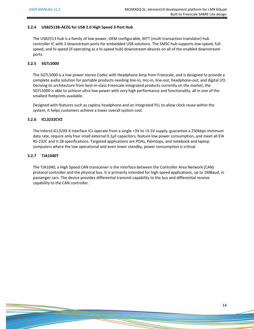
3.3.1 Power Input Jack
The 5V/4A AC-to-DC power supply that comes with the board is plugged into the Power Jack (J10) on the
board. It is not recommended to use a higher voltage since possible damage to the board may result due to
failure of the protection circuitry.
Figure 32 SABRE Lite Board
Table 31 Power Interface
J10
Pin Signal Function
1 GND GND
2 NC NC
3 +5V Power supply (+5V) 4A (Type)
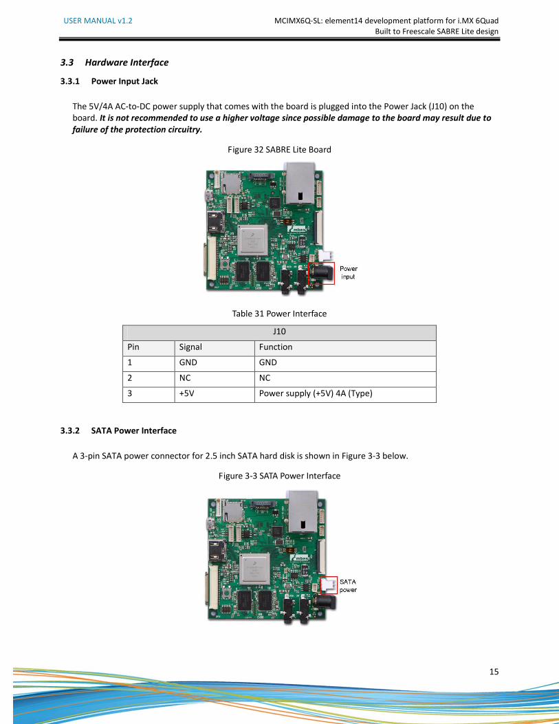
3.3.2 SATA Power Interface
A 3-pin SATA power connector for 2.5 inch SATA hard disk is shown in Figure 3-3 below.
Figure 3-3 SATA Power Interface
USER MANUAL v1.2 MCIMX6Q-SL: element14 development platform for i.MX 6Quad
Built to Freescale SABRE Lite design
16
Table 32 SATA Power Interface
J19
Pin Signal Function
1 +3.3V 3.3V output
2 GND GND
3 +5V 5V output
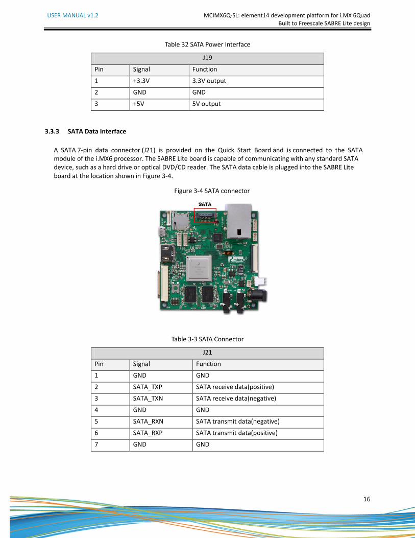
3.3.3 SATA Data Interface
A SATA 7-pin data connector (J21) is provided on the Quick Start Board and is connected to the SATA
module of the i.MX6 processor. The SABRE Lite board is capable of communicating with any standard SATA
device, such as a hard drive or optical DVD/CD reader. The SATA data cable is plugged into the SABRE Lite
board at the location shown in Figure 3-4.
Figure 3-4 SATA connector
Table 3-3 SATA Connector
J21
Pin Signal Function
1 GND GND
2 SATA_TXP SATA receive data(positive)
3 SATA_TXN SATA receive data(negative)
4 GND GND
5 SATA_RXN SATA transmit data(negative)
6 SATA_RXP SATA transmit data(positive)
7 GND GND
USER MANUAL v1.2 MCIMX6Q-SL: element14 development platform for i.MX 6Quad
Built to Freescale SABRE Lite design
17
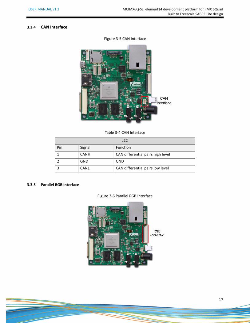
3.3.4 CAN Interface
Figure 3-5 CAN Interface
Table 3-4 CAN Interface
J22
Pin Signal Function
1 CANH CAN differential pairs high level
2 GND GND
3 CANL CAN differential pairs low level
3.3.5 Parallel RGB Interface
Figure 3-6 Parallel RGB Interface
USER MANUAL v1.2 MCIMX6Q-SL: element14 development platform for i.MX 6Quad
Built to Freescale SABRE Lite design
18
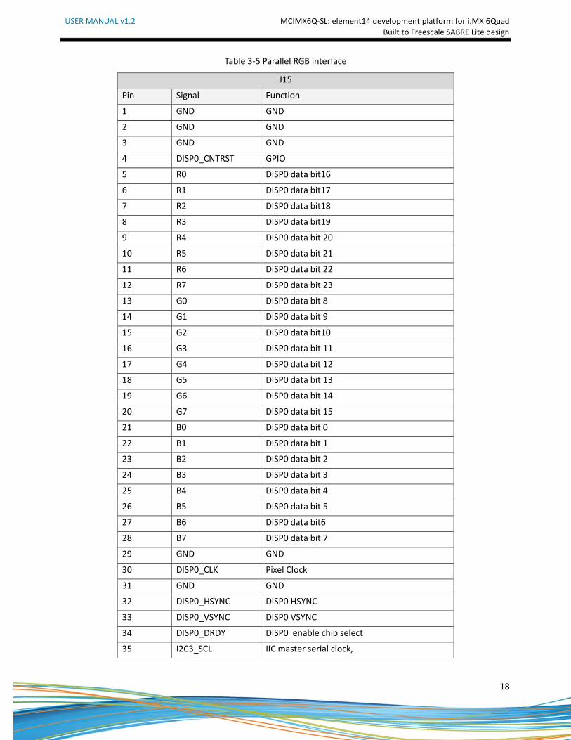
Table 3-5 Parallel RGB interface
J15
Pin Signal Function
1 GND GND
2 GND GND
3 GND GND
4 DISP0_CNTRST GPIO
5 R0 DISP0 data bit16
6 R1 DISP0 data bit17
7 R2 DISP0 data bit18
8 R3 DISP0 data bit19
9 R4 DISP0 data bit 20
10 R5 DISP0 data bit 21
11 R6 DISP0 data bit 22
12 R7 DISP0 data bit 23
13 G0 DISP0 data bit 8
14 G1 DISP0 data bit 9
15 G2 DISP0 data bit10
16 G3 DISP0 data bit 11
17 G4 DISP0 data bit 12
18 G5 DISP0 data bit 13
19 G6 DISP0 data bit 14
20 G7 DISP0 data bit 15
21 B0 DISP0 data bit 0
22 B1 DISP0 data bit 1
23 B2 DISP0 data bit 2
24 B3 DISP0 data bit 3
25 B4 DISP0 data bit 4
26 B5 DISP0 data bit 5
27 B6 DISP0 data bit6
28 B7 DISP0 data bit 7
29 GND GND
30 DISP0_CLK Pixel Clock
31 GND GND
32 DISP0_HSYNC DISP0 HSYNC
33 DISP0_VSYNC DISP0 VSYNC
34 DISP0_DRDY DISP0 enable chip select
35 I2C3_SCL IIC master serial clock,
USER MANUAL v1.2 MCIMX6Q-SL: element14 development platform for i.MX 6Quad
Built to Freescale SABRE Lite design
19
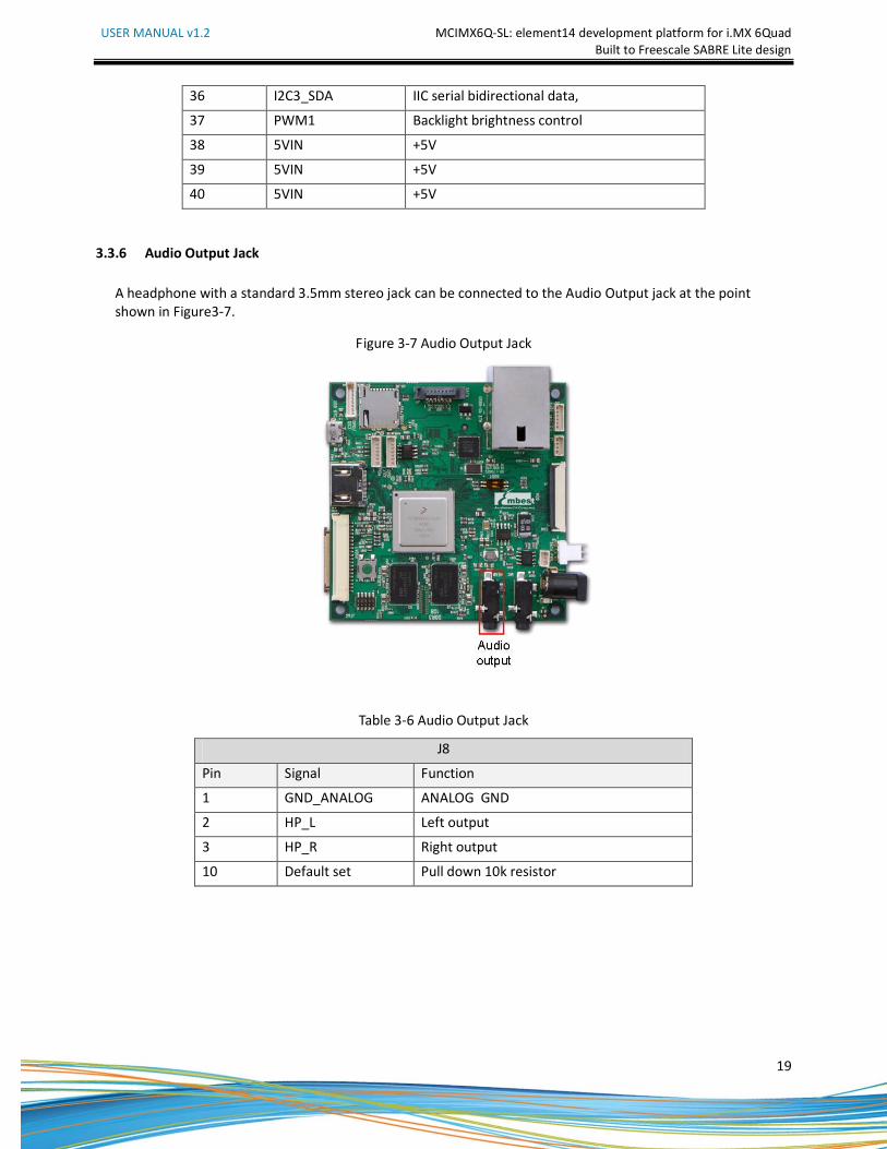
36 I2C3_SDA IIC serial bidirectional data,
37 PWM1 Backlight brightness control
38 5VIN +5V
39 5VIN +5V
40 5VIN +5V
3.3.6 Audio Output Jack
A headphone with a standard 3.5mm stereo jack can be connected to the Audio Output jack at the point
shown in Figure3-7.
Figure 3-7 Audio Output Jack
Table 3-6 Audio Output Jack
J8
Pin Signal Function
1 GND_ANALOG ANALOG GND
2 HP_L Left output
3 HP_R Right output
10 Default set Pull down 10k resistor
USER MANUAL v1.2 MCIMX6Q-SL: element14 development platform for i.MX 6Quad
Built to Freescale SABRE Lite design
20
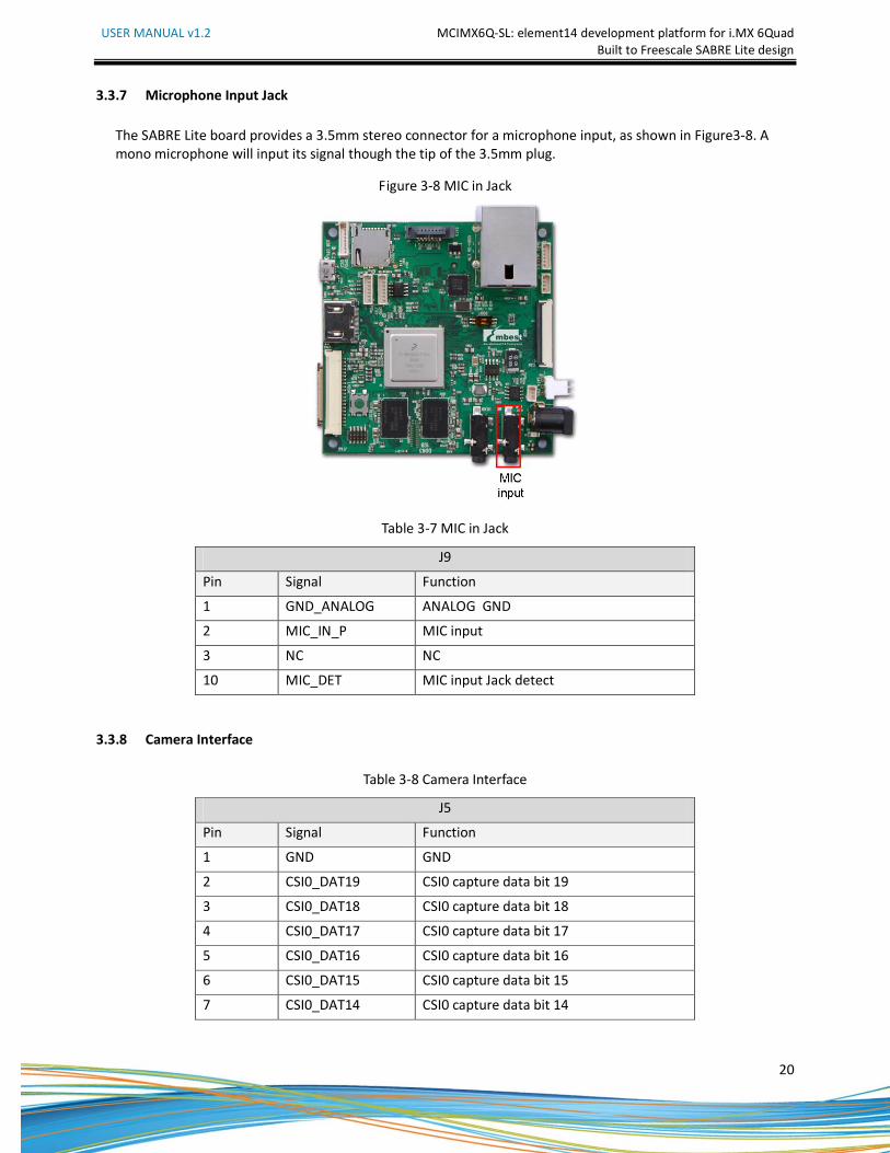
3.3.7 Microphone Input Jack
The SABRE Lite board provides a 3.5mm stereo connector for a microphone input, as shown in Figure3-8. A
mono microphone will input its signal though the tip of the 3.5mm plug.
Figure 3-8 MIC in Jack
Table 3-7 MIC in Jack
J9
Pin Signal Function
1 GND_ANALOG ANALOG GND
2 MIC_IN_P MIC input
3 NC NC
10 MIC_DET MIC input Jack detect
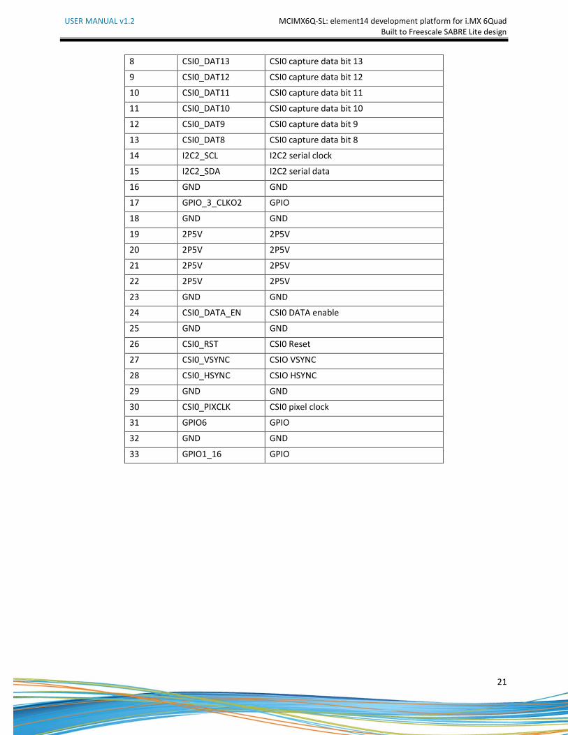
3.3.8 Camera Interface
Table 3-8 Camera Interface
J5
Pin Signal Function
1 GND GND
2 CSI0_DAT19 CSI0 capture data bit 19
3 CSI0_DAT18 CSI0 capture data bit 18
4 CSI0_DAT17 CSI0 capture data bit 17
5 CSI0_DAT16 CSI0 capture data bit 16
6 CSI0_DAT15 CSI0 capture data bit 15
7 CSI0_DAT14 CSI0 capture data bit 14
USER MANUAL v1.2 MCIMX6Q-SL: element14 development platform for i.MX 6Quad
Built to Freescale SABRE Lite design
21
8 CSI0_DAT13 CSI0 capture data bit 13
9 CSI0_DAT12 CSI0 capture data bit 12
10 CSI0_DAT11 CSI0 capture data bit 11
11 CSI0_DAT10 CSI0 capture data bit 10
12 CSI0_DAT9 CSI0 capture data bit 9
13 CSI0_DAT8 CSI0 capture data bit 8
14 I2C2_SCL I2C2 serial clock
15 I2C2_SDA I2C2 serial data
16 GND GND
17 GPIO_3_CLKO2 GPIO
18 GND GND
19 2P5V 2P5V
20 2P5V 2P5V
21 2P5V 2P5V
22 2P5V 2P5V
23 GND GND
24 CSI0_DATA_EN CSI0 DATA enable
25 GND GND
26 CSI0_RST CSI0 Reset
27 CSI0_VSYNC CSIO VSYNC
28 CSI0_HSYNC CSIO HSYNC
29 GND GND
30 CSI0_PIXCLK CSI0 pixel clock
31 GPIO6 GPIO
32 GND GND
33 GPIO1_16 GPIO
USER MANUAL v1.2 MCIMX6Q-SL: element14 development platform for i.MX 6Quad
Built to Freescale SABRE Lite design
22
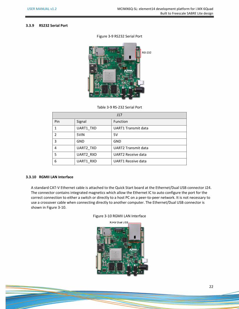
3.3.9 RS232 Serial Port
Figure 3-9 RS232 Serial Port
Table 3-9 RS-232 Serial Port
J17
Pin Signal Function
1 UART1_TXD UART1 Transmit data
2 5VIN 5V
3 GND GND
4 UART2_TXD UART2 Transmit data
5 UART2_RXD UART2 Receive data
6 UART1_RXD UART1 Receive data
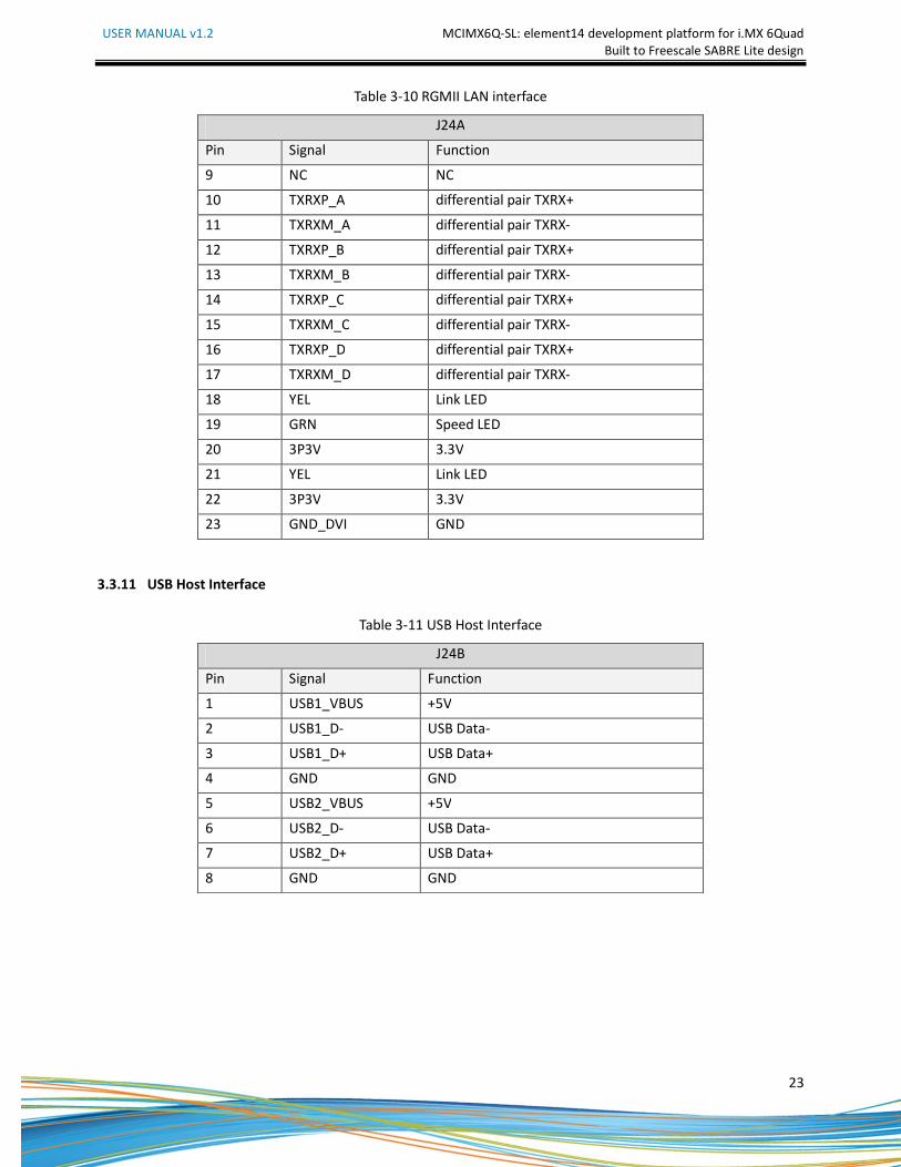
3.3.10 RGMII LAN Interface
A standard CAT-V Ethernet cable is attached to the Quick Start board at the Ethernet/Dual USB connector J24.
The connector contains integrated magnetics which allow the Ethernet IC to auto configure the port for the
correct connection to either a switch or directly to a host PC on a peer-to-peer network. It is not necessary to
use a crossover cable when connecting directly to another computer. The Ethernet/Dual USB connector is
shown in Figure 3-10.
Figure 3-10 RGMII LAN Interface
USER MANUAL v1.2 MCIMX6Q-SL: element14 development platform for i.MX 6Quad
Built to Freescale SABRE Lite design
23
Table 3-10 RGMII LAN interface
J24A
Pin Signal Function
9 NC NC
10 TXRXP_A differential pair TXRX+
11 TXRXM_A differential pair TXRX-
12 TXRXP_B differential pair TXRX+
13 TXRXM_B differential pair TXRX-
14 TXRXP_C differential pair TXRX+
15 TXRXM_C differential pair TXRX-
16 TXRXP_D differential pair TXRX+
17 TXRXM_D differential pair TXRX-
18 YEL Link LED
19 GRN Speed LED
20 3P3V 3.3V
21 YEL Link LED
22 3P3V 3.3V
23 GND_DVI GND
3.3.11 USB Host Interface
Table 3-11 USB Host Interface
J24B
Pin Signal Function
1 USB1_VBUS +5V
2 USB1_D- USB Data-
3 USB1_D+ USB Data+
4 GND GND
5 USB2_VBUS +5V
6 USB2_D- USB Data-
7 USB2_D+ USB Data+
8 GND GND
USER MANUAL v1.2 MCIMX6Q-SL: element14 development platform for i.MX 6Quad
Built to Freescale SABRE Lite design
24
Table 3-12 USB Host Interface
J1
Pin Signal Function
1 5VIN +5V
2 USBDN_DM3 USB Data-
3 USBDN_DP3 USB Data+
4 GND GND
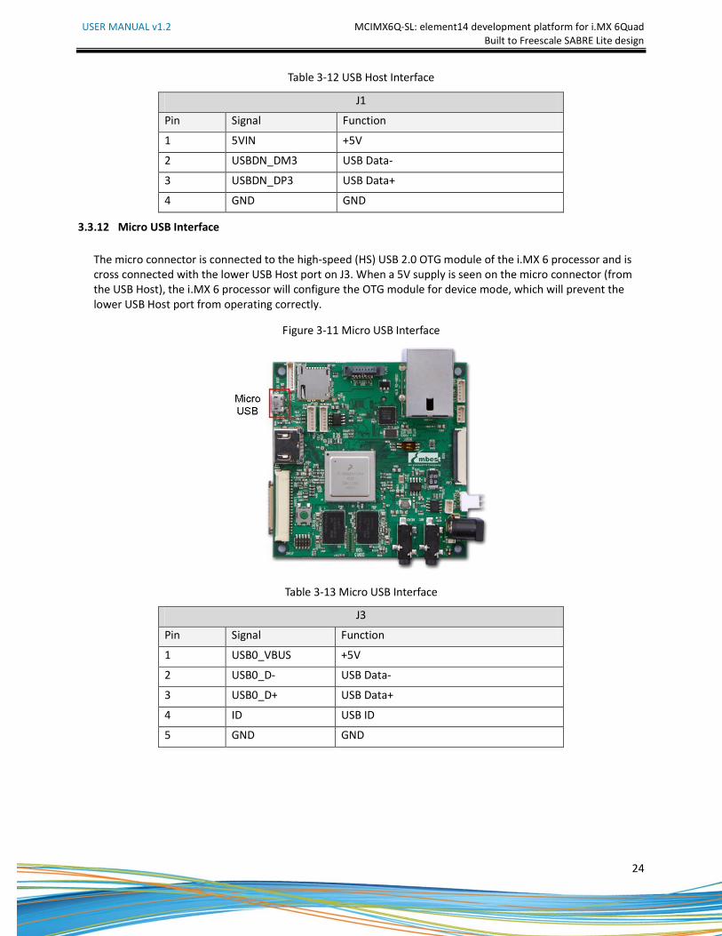
3.3.12 Micro USB Interface
The micro connector is connected to the high-speed (HS) USB 2.0 OTG module of the i.MX 6 processor and is
cross connected with the lower USB Host port on J3. When a 5V supply is seen on the micro connector (from
the USB Host), the i.MX 6 processor will configure the OTG module for device mode, which will prevent the
lower USB Host port from operating correctly.
Figure 3-11 Micro USB Interface
Table 3-13 Micro USB Interface
J3
Pin Signal Function
1 USB0_VBUS +5V
2 USB0_D- USB Data-
3 USB0_D+ USB Data+
4 ID USB ID
5 GND GND
USER MANUAL v1.2 MCIMX6Q-SL: element14 development platform for i.MX 6Quad
Built to Freescale SABRE Lite design
25
3.3.13 SD Card Interface
Table 3-14 SD Card Interface
J18
Pin Signal Function
1 SD3_DAT3 Card data 3
2 SD3_CMD Command Signal
3 GND GND
4 3P3V 3P3V
5 SD3_CLK Clock
6 VSS GND
7 SD3_DAT0 Card data 0
8 SD3_DAT1 Card data 1
9 SD3_DAT2 Card data 2
10 SD3_CD Card detect
11 SD3_WP Card write protected
12 GND GND
13 GND GND
14 GND GND
15 GND GND
3.3.14 JTAG Interface
Table 3-15 JTAG Interface
J13
Pin Signal Function
1 3P3V 3.3V
2 JTAG_TMS Test mode select
3 GND GND
4 JTAG_TCK Test clock
5 GND GND
6 JTAG_TDO Test data output
7 JTAG_MOD Test mode
8 JTAG_TDI Test data input
9 JTAG_nTRST Test system reset
10 RESET_N RESET for TPS3808
USER MANUAL v1.2 MCIMX6Q-SL: element14 development platform for i.MX 6Quad
Built to Freescale SABRE Lite design
26
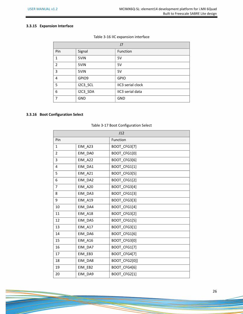
3.3.15 Expansion Interface
Table 3-16 IIC expansion interface
J7
Pin Signal Function
1 5VIN 5V
2 5VIN 5V
3 5VIN 5V
4 GPIO9 GPIO
5 I2C3_SCL IIC3 serial clock
6 I2C3_SDA IIC3 serial data
7 GND GND
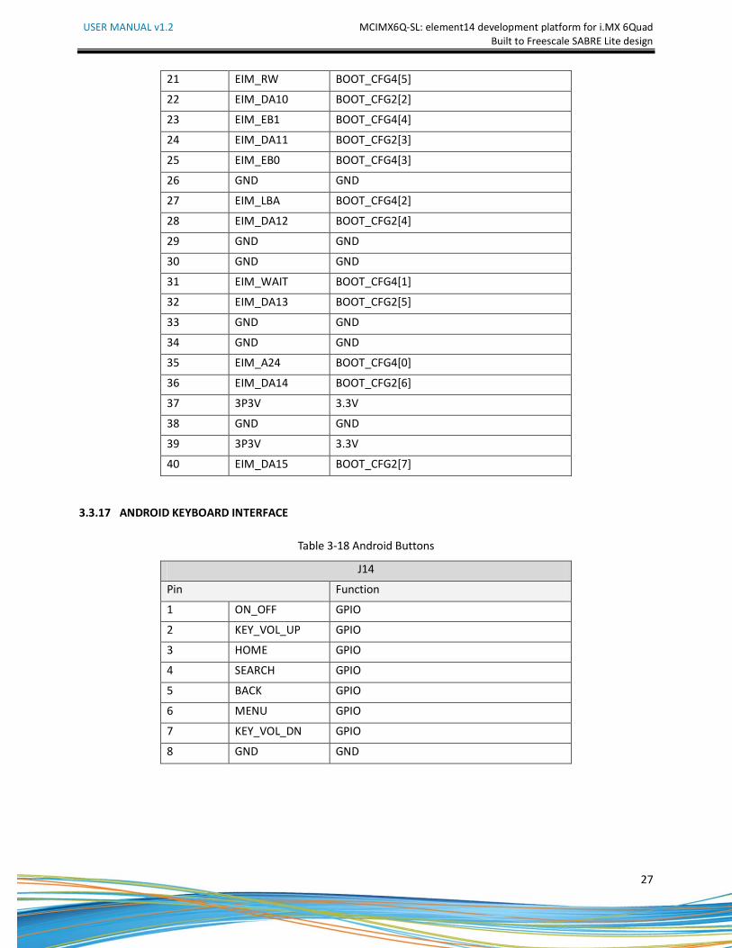
3.3.16 Boot Configuration Select
Table 3-17 Boot Configuration Select
J12
Pin Function
1 EIM_A23 BOOT_CFG3[7]
2 EIM_DA0 BOOT_CFG1[0]
3 EIM_A22 BOOT_CFG3[6]
4 EIM_DA1 BOOT_CFG1[1]
5 EIM_A21 BOOT_CFG3[5]
6 EIM_DA2 BOOT_CFG1[2]
7 EIM_A20 BOOT_CFG3[4]
8 EIM_DA3 BOOT_CFG1[3]
9 EIM_A19 BOOT_CFG3[3]
10 EIM_DA4 BOOT_CFG1[4]
11 EIM_A18 BOOT_CFG3[2]
12 EIM_DA5 BOOT_CFG1[5]
13 EIM_A17 BOOT_CFG3[1]
14 EIM_DA6 BOOT_CFG1[6]
15 EIM_A16 BOOT_CFG3[0]
16 EIM_DA7 BOOT_CFG1[7]
17 EIM_EB3 BOOT_CFG4[7]
18 EIM_DA8 BOOT_CFG2[0]]
19 EIM_EB2 BOOT_CFG4[6]
20 EIM_DA9 BOOT_CFG2[1]
USER MANUAL v1.2 MCIMX6Q-SL: element14 development platform for i.MX 6Quad
Built to Freescale SABRE Lite design
27
21 EIM_RW BOOT_CFG4[5]
22 EIM_DA10 BOOT_CFG2[2]
23 EIM_EB1 BOOT_CFG4[4]
24 EIM_DA11 BOOT_CFG2[3]
25 EIM_EB0 BOOT_CFG4[3]
26 GND GND
27 EIM_LBA BOOT_CFG4[2]
28 EIM_DA12 BOOT_CFG2[4]
29 GND GND
30 GND GND
31 EIM_WAIT BOOT_CFG4[1]
32 EIM_DA13 BOOT_CFG2[5]
33 GND GND
34 GND GND
35 EIM_A24 BOOT_CFG4[0]
36 EIM_DA14 BOOT_CFG2[6]
37 3P3V 3.3V
38 GND GND
39 3P3V 3.3V
40 EIM_DA15 BOOT_CFG2[7]
3.3.17 ANDROID KEYBOARD INTERFACE
Table 3-18 Android Buttons
J14
Pin Function
1 ON_OFF GPIO
2 KEY_VOL_UP GPIO
3 HOME GPIO
4 SEARCH GPIO
5 BACK GPIO
6 MENU GPIO
7 KEY_VOL_DN GPIO
8 GND GND
USER MANUAL v1.2 MCIMX6Q-SL: element14 development platform for i.MX 6Quad
Built to Freescale SABRE Lite design
28
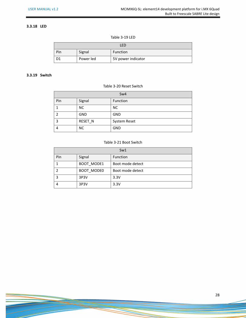
3.3.18 LED
Table 3-19 LED
LED
Pin Signal Function
D1 Power led 5V power indicator
3.3.19 Switch
Table 3-20 Reset Switch
Sw4
Pin Signal Function
1 NC NC
2 GND GND
3 RESET_N System Reset
4 NC GND
Table 3-21 Boot Switch
Sw1
Pin Signal Function
1 BOOT_MODE1 Boot mode detect
2 BOOT_MODE0 Boot mode detect
3 3P3V 3.3V
4 3P3V 3.3V
USER MANUAL v1.2 MCIMX6Q-SL: element14 development platform for i.MX 6Quad
Built to Freescale SABRE Lite design
29
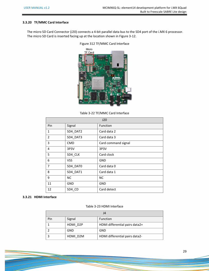
3.3.20 TF/MMC Card Interface
The micro SD Card Connector (J20) connects a 4-bit parallel data bus to the SD4 port of the i.MX 6 processor.
The micro SD Card is inserted facing up at the location shown in Figure 3-12.
Figure 312 TF/MMC Card Interface
Table 3-22 TF/MMC Card Interface
J20
Pin Signal Function
1 SD4_DAT2 Card data 2
2 SD4_DAT3 Card data 3
3 CMD Card command signal
4 3P3V 3P3V
5 SD4_CLK Card clock
6 VSS GND
7 SD4_DAT0 Card data 0
8 SD4_DAT1 Card data 1
9 NC NC
11 GND GND
12 SD4_CD Card detect
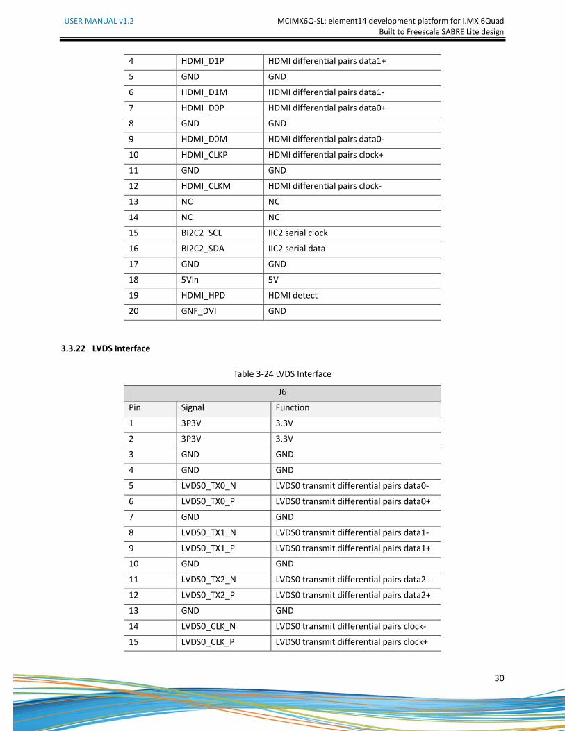
3.3.21 HDMI Interface
Table 3-23 HDMI Interface
J4
Pin Signal Function
1 HDMI_D2P HDMI differential pairs data2+
2 GND GND
3 HDMI_D2M HDMI differential pairs data2-
USER MANUAL v1.2 MCIMX6Q-SL: element14 development platform for i.MX 6Quad
Built to Freescale SABRE Lite design
30
4 HDMI_D1P HDMI differential pairs data1+
5 GND GND
6 HDMI_D1M HDMI differential pairs data1-
7 HDMI_D0P HDMI differential pairs data0+
8 GND GND
9 HDMI_D0M HDMI differential pairs data0-
10 HDMI_CLKP HDMI differential pairs clock+
11 GND GND
12 HDMI_CLKM HDMI differential pairs clock-
13 NC NC
14 NC NC
15 BI2C2_SCL IIC2 serial clock
16 BI2C2_SDA IIC2 serial data
17 GND GND
18 5Vin 5V
19 HDMI_HPD HDMI detect
20 GNF_DVI GND
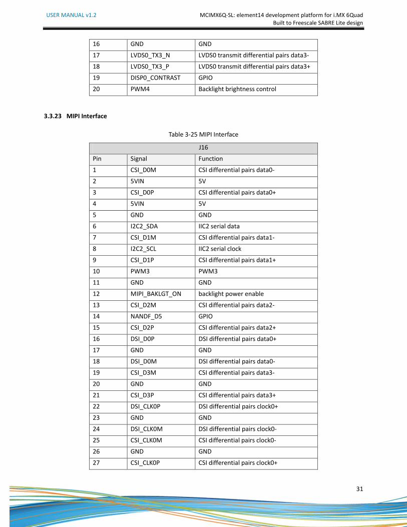
3.3.22 LVDS Interface
Table 3-24 LVDS Interface
J6
Pin Signal Function
1 3P3V 3.3V
2 3P3V 3.3V
3 GND GND
4 GND GND
5 LVDS0_TX0_N LVDS0 transmit differential pairs data0-
6 LVDS0_TX0_P LVDS0 transmit differential pairs data0+
7 GND GND
8 LVDS0_TX1_N LVDS0 transmit differential pairs data1-
9 LVDS0_TX1_P LVDS0 transmit differential pairs data1+
10 GND GND
11 LVDS0_TX2_N LVDS0 transmit differential pairs data2-
12 LVDS0_TX2_P LVDS0 transmit differential pairs data2+
13 GND GND
14 LVDS0_CLK_N LVDS0 transmit differential pairs clock-
15 LVDS0_CLK_P LVDS0 transmit differential pairs clock+
USER MANUAL v1.2 MCIMX6Q-SL: element14 development platform for i.MX 6Quad
Built to Freescale SABRE Lite design
31
16 GND GND
17 LVDS0_TX3_N LVDS0 transmit differential pairs data3-
18 LVDS0_TX3_P LVDS0 transmit differential pairs data3+
19 DISP0_CONTRAST GPIO
20 PWM4 Backlight brightness control
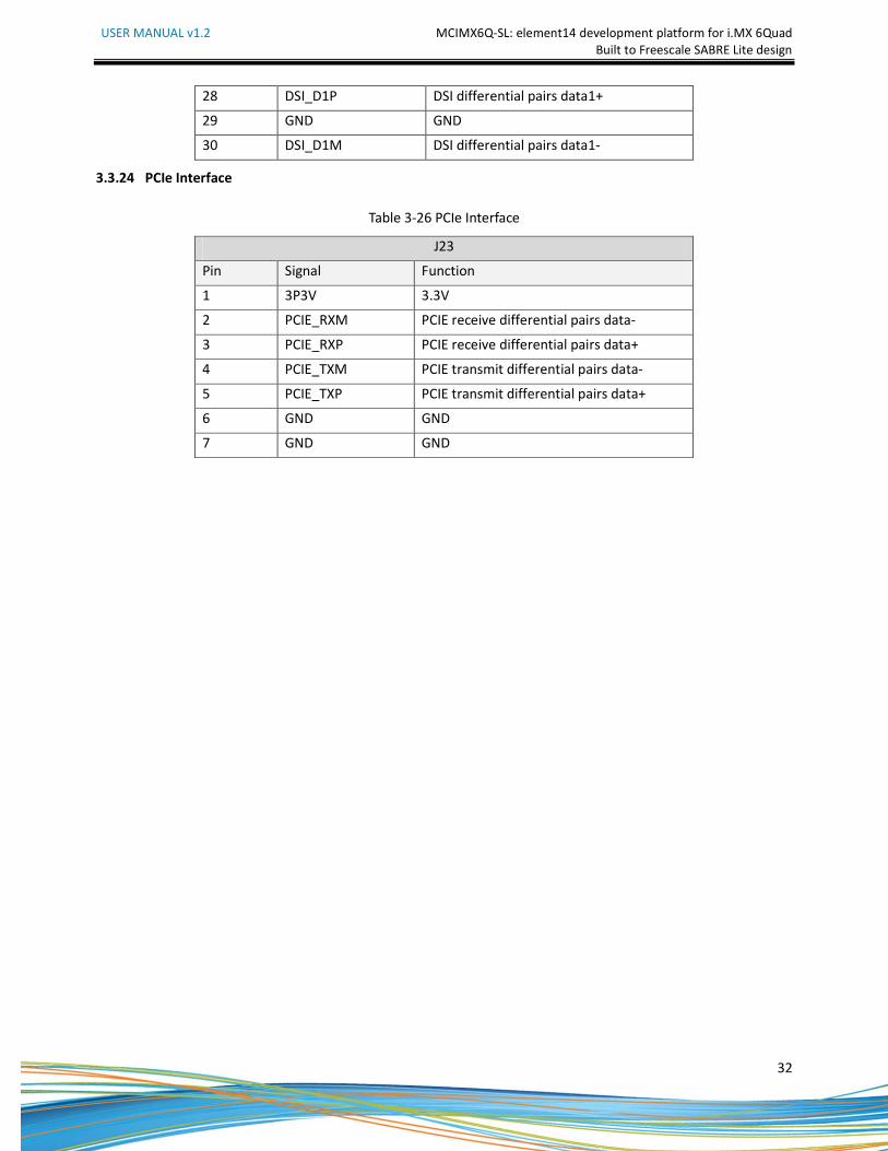
3.3.23 MIPI Interface
Table 3-25 MIPI Interface
J16
Pin Signal Function
1 CSI_D0M CSI differential pairs data0-
2 5VIN 5V
3 CSI_D0P CSI differential pairs data0+
4 5VIN 5V
5 GND GND
6 I2C2_SDA IIC2 serial data
7 CSI_D1M CSI differential pairs data1-
8 I2C2_SCL IIC2 serial clock
9 CSI_D1P CSI differential pairs data1+
10 PWM3 PWM3
11 GND GND
12 MIPI_BAKLGT_ON backlight power enable
13 CSI_D2M CSI differential pairs data2-
14 NANDF_D5 GPIO
15 CSI_D2P CSI differential pairs data2+
16 DSI_D0P DSI differential pairs data0+
17 GND GND
18 DSI_D0M DSI differential pairs data0-
19 CSI_D3M CSI differential pairs data3-
20 GND GND
21 CSI_D3P CSI differential pairs data3+
22 DSI_CLK0P DSI differential pairs clock0+
23 GND GND
24 DSI_CLK0M DSI differential pairs clock0-
25 CSI_CLK0M CSI differential pairs clock0-
26 GND GND
27 CSI_CLK0P CSI differential pairs clock0+
USER MANUAL v1.2 MCIMX6Q-SL: element14 development platform for i.MX 6Quad
Built to Freescale SABRE Lite design
32
28 DSI_D1P DSI differential pairs data1+
29 GND GND
30 DSI_D1M DSI differential pairs data1-
3.3.24 PCIe Interface
Table 3-26 PCIe Interface
J23
Pin Signal Function
1 3P3V 3.3V
2 PCIE_RXM PCIE receive differential pairs data-
3 PCIE_RXP PCIE receive differential pairs data+
4 PCIE_TXM PCIE transmit differential pairs data-
5 PCIE_TXP PCIE transmit differential pairs data+
6 GND GND
7 GND GND
USER MANUAL v1.2 MCIMX6Q-SL: element14 development platform for i.MX 6Quad
Built to Freescale SABRE Lite design
33
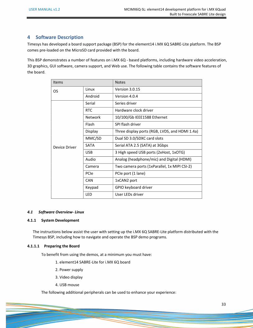
4 Software Description
Timesys has developed a board support package (BSP) for the element14 i.MX 6Q SABRE-Lite platform. The BSP
comes pre-loaded on the MicroSD card provided with the board.
This BSP demonstrates a number of features on i.MX 6Q - based platforms, including hardware video acceleration,
3D graphics, GUI software, camera support, and Web use. The following table contains the software features of
the board.
Items Notes
OS Linux Version 3.0.15
Android Version 4.0.4
Device Driver
Serial Series driver
RTC Hardware clock driver
Network 10/100/Gb IEEE1588 Ethernet
Flash SPI flash driver
Display Three display ports (RGB, LVDS, and HDMI 1.4a)
MMC/SD Dual SD 3.0/SDXC card slots
SATA Serial ATA 2.5 (SATA) at 3Gbps
USB 3 High speed USB ports (2xHost, 1xOTG)
Audio Analog (headphone/mic) and Digital (HDMI)
audio Camera Two camera ports (1xParallel, 1x MIPI CSI-2)
PCIe PCIe port (1 lane)
CAN 1xCAN2 port
Keypad GPIO keyboard driver
LED User LEDs driver
4.1 Software Overview- Linux
4.1.1 System Development
The instructions below assist the user with setting up the i.MX 6Q SABRE-Lite platform distributed with the
Timesys BSP, including how to navigate and operate the BSP demo programs.
4.1.1.1 Preparing the Board
To benefit from using the demos, at a minimum you must have:
1. element14 SABRE-Lite for i.MX 6Q board
2. Power supply
3. Video display
4. USB mouse
The following additional peripherals can be used to enhance your experience:
USER MANUAL v1.2 MCIMX6Q-SL: element14 development platform for i.MX 6Quad
Built to Freescale SABRE Lite design
34
5. Ethernet cord
6. Camera
7. RS-232 serial cable
8. USB keyboard
Connect the display, USB mouse, and optionally the ethernet cord, camera and serial cable to your
SABRE-Lite board. Then insert the power supply plug into the power port on your board.
4.1.1.2 Booting your Board
Several seconds after supplying power to the SABRE-Lite, you will see the Timesys logo displayed on your video
display. Wait for around 30 seconds for the boot process to complete.
At the conclusion of the boot, the Qt demo launcher application will begin, characterized by a number of
application thumbnails arranged in a horizontal line, with a mouse positioned at center-screen.
NOTE: A number of displays are supported as defaults for the BSP distributed with your board. If you are using
a non-default display, then you may have to manually set the U-Boot environment for your board in order to
see the desired graphical output. For information on how to do this, sign up for your free LinuxLink account at
http://linuxlink.timesys.com , and see the SABRE-Lite Getting Started Guide at
https://linuxlink.timesys.com/docs/gsg/i.MX6QSABRELite .
4.1.1.3 Using the Demo
The demo begins in the Qt application called 'fluidlauncher'. A number of demos can be launched from here.
In order to navigate through the menu, click on with the USB mouse on a side of the window in the direction
you wish to cycle the application thumbnails. For instance, if you wish to access an application whose
thumbnail is to the left of center, position your mouse on the left side of the screen over black space and click
several times until the thumbnail for your application is moved to center.
Once the thumbnail for the desired application is centered, click on it to launch the demo.
1. Timesys Theatre
Timesys theatre showcases a number of the unique capabilites of the i.MX 6Q hardware, most notably:
• Hardware video acceleration
• Multi-core processing
• Video streaming from camera
The main menu for the theatre provides four options:
• Accelerated Video: Play a video using Freescale accelerated codecs
• Non-accelerated Video: Play same video with standard, unaccelerated gstreamer and ffmpeg
codecs
• Camera: see the video capture stream from an attached camera. Includes non-accelerated
gstreamer pipeline elements
USER MANUAL v1.2 MCIMX6Q-SL: element14 development platform for i.MX 6Quad
Built to Freescale SABRE Lite design
35
• Exit: leave this demo
When selecting any of the first three menu options, you may stress-test the video pipeline to see the
impact of additional computational work on video that is accelerated and non-accelerated. In order to do
this:
• Select "Accelerated Video," "Non-accelerated Video," or "Camera"
• Click anywhere on the screen to bring up the Qt GUI overlay
• Add additional computational load with the "Add CPU Load" button
• View the per-core CPU usage in the top-left corner of the screen
Note that you will see notable video slowdown when adding CPU load for the non-accelerated video
pipeline. Alternatively, you should see nearly no slowdown, if any, for the accelerated pipeline.
To return to the main menu from any of the video streams, hit the "Stop" button in the lower-right corner
of the Qt GUI overlay.
2. Vivante GPU demos
Vivante provides a binary package of OpenGLES libraries to make 3D graphics acceleration available to the
developer on an i.MX 6Q - based platform.
Two Vivante-developed demos, "3D Spinning Orb" and "3D Spinning Block," show the SABRE-Lite's 3D
graphics acceleration capabilities in a number of simple tests with texturized 3D objects.
3. Timesys website
If your element14 i.MX 6Q SABRE-Lite is connected to a DHCP and DNS server through an ethernet cable,
you can access the Web via the Qt application called 'fancybrowser.'
This demo will route you to the Timesys website, after which you may navigate about the Web as you
would with a standard Web browser.
4. Qt applications
Two Qt demos, "Vector Deformation" and "Path Stroking," have been included to demonstrate the
capabilities of Qt software for this platform.
Qt is a toolkit that provides the ability to construct complex and rich GUI environments for your
applications. The two demos above show a wide range of GUI elements available to the Qt developer.
4.1.2 For More Information
The Linux kernel and software for this BSP was built using the Timesys Factory.
The Factory provides a toolchain, sources, and build infrastructure that can be used for rapid development and
customization of an embedded Linux OS for your target platform. At this time, over 100 reference boards and
1300 packages are integrated into the Factory build system.

USER MANUAL v1.2 MCIMX6Q-SL: element14 development platform for i.MX 6Quad
Built to Freescale SABRE Lite design
36
To build your own free Linux BSP for your element14 i.MX 6Q SABRE-Lite, visit
http://www.timesys.com/embedded-linux/resources/dev-center/imx6. From here, you can find further
instructions on building a custom Linux distribution using Timesys's LinuxLink, documentation on booting your
board, and other materials to help you support Linux for your platform.
USER MANUAL v1.2 MCIMX6Q-SL: element14 development platform for i.MX 6Quad
Built to Freescale SABRE Lite design
37
4.2 Android
4.2.1 Quick Guide
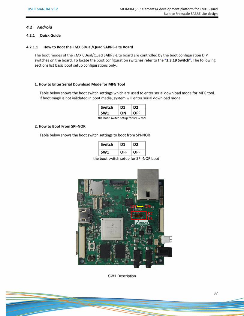
4.2.1.1 How to Boot the i.MX 6Dual/Quad SABRE-Lite Board
The boot modes of the i.MX 6Dual/Quad SABRE-Lite board are controlled by the boot configuration DIP
switches on the board. To locate the boot configuration switches refer to the ”3.3.19 Switch”. The following
sections list basic boot setup configurations only.
1. How to Enter Serial Download Mode for MFG Tool
Table below shows the boot switch settings which are used to enter serial download mode for MFG tool.
If bootimage is not validated in boot media, system will enter serial download mode.
Switch D1 D2
SW1 ON OFF the boot switch setup for MFG tool
2. How to Boot From SPI-NOR
Table below shows the boot switch settings to boot from SPI-NOR
Switch D1 D2
SW1 OFF OFF
the boot switch setup for SPI-NOR boot
SW1 Description
D2
D1
ON OFF
USER MANUAL v1.2 MCIMX6Q-SL: element14 development platform for i.MX 6Quad
Built to Freescale SABRE Lite design
38
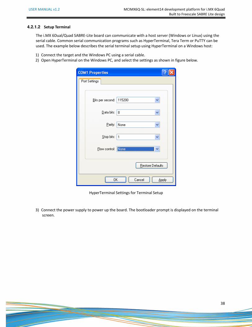
4.2.1.2 Setup Terminal
The i.MX 6Dual/Quad SABRE-Lite board can communicate with a host server (Windows or Linux) using the
serial cable. Common serial communication programs such as HyperTerminal, Tera Term or PuTTY can be
used. The example below describes the serial terminal setup using HyperTerminal on a Windows host:
1) Connect the target and the Windows PC using a serial cable.
2) Open HyperTerminal on the Windows PC, and select the settings as shown in figure below.
HyperTerminal Settings for Terminal Setup
3) Connect the power supply to power up the board. The bootloader prompt is displayed on the terminal
screen.
USER MANUAL v1.2 MCIMX6Q-SL: element14 development platform for i.MX 6Quad
Built to Freescale SABRE Lite design
39
4.2.2 Download Images
i.MX Android can be booted up in two ways:
1) Boot from TF card
2) Boot from NFS (networking)
Before boot, you should program the bootloader, kernel, ramdisk and rootfs images into the main storage
device (TF card) or unpack the NFS root filesystem into the NFS server root.
The following download methods are supported for i.MX6Q Sabrelite:
1) MFGTool to download all images to TF card
2) Using dd command to download all images to TF card
4.2.2.1 System on TF card
The images needed to create an android system on TF card are listed below:
1) u-boot image: u-boot.bin
2) boot image: boot.img
3) Android system root image: system.img
4) Recovery root image: recovery.img
The images can be obtained from the release package or they can be built out.
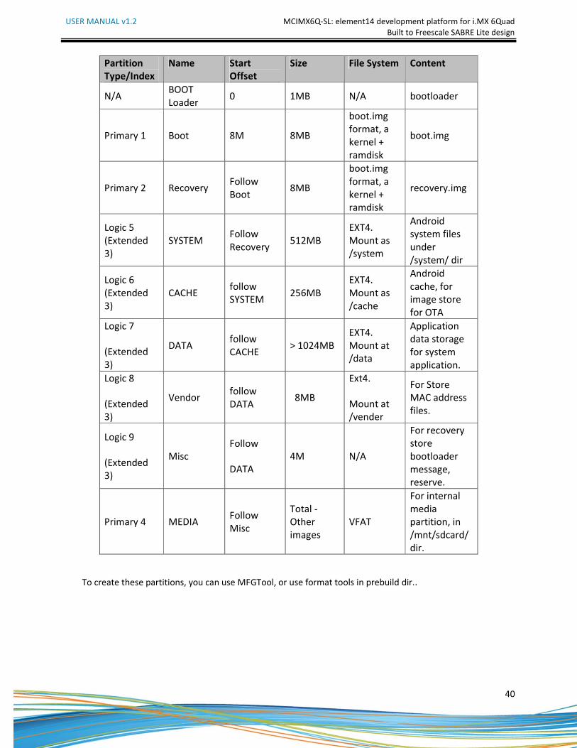
Storage Partitions
The layout of the TF card for Android system is shown below:
1) [Partition type/index] is which defined in the MBR.
2) [Name] is only meaningful in android. You can ignore it when creating these partitions.
3) [Start Offset] shows where partition is started, unit in MB.
The SYSTEM partition is used to put the built out android system image. The DATA is used to put
applications’ unpacked codes/data, system configuration database, etc. In normal boot mode, the root file
system is mounted from uramdisk. In recovery mode, the root file system is mounted from the RECOVERY
partition.
USER MANUAL v1.2 MCIMX6Q-SL: element14 development platform for i.MX 6Quad
Built to Freescale SABRE Lite design
40
Partition
Type/Index
Name Start
Offset
Size File System Content
N/A BOOT
Loader 0 1MB N/A bootloader
Primary 1 Boot 8M 8MB
boot.img
format, a
kernel +
ramdisk
boot.img
Primary 2 Recovery Follow
Boot 8MB
boot.img
format, a
kernel +
ramdisk
recovery.img
Logic 5
(Extended
3)
SYSTEM Follow
Recovery 512MB
EXT4.
Mount as
/system
Android
system files
under
/system/ dir
Logic 6
(Extended
3)
CACHE follow
SYSTEM 256MB
EXT4.
Mount as
/cache
Android
cache, for
image store
for OTA
Logic 7
(Extended
3)
DATA follow
CACHE > 1024MB
EXT4.
Mount at
/data
Application
data storage
for system
application.
Logic 8
(Extended
3)
Vendor follow
DATA 8MB
Ext4.
Mount at
/vender
For Store
MAC address
files.
Logic 9
(Extended
3)
Misc
Follow
DATA
4M N/A
For recovery
store
bootloader
message,
reserve.
Primary 4 MEDIA Follow
Misc
Total -
Other
images
VFAT
For internal
media
partition, in
/mnt/sdcard/
dir.
To create these partitions, you can use MFGTool, or use format tools in prebuild dir..

USER MANUAL v1.2 MCIMX6Q-SL: element14 development platform for i.MX 6Quad
Built to Freescale SABRE Lite design
41
1. Downloading Images using MFG Tool
This chapter describes the procedure for using the MFG tool to download Android images.
1) Installing the MFG Tools
Please download Android Image Programming tools “Mfgtools-Rel-12.04.01_ER_MX6Q_UPDATER”
into your windows PC from www.element14.com/iMX6.
2) Usage
Read the MFG tool documentation in the "Document" folder, before using the MFG tool.
The MFG tool follows the instructions in "Profiles\MX6Q Linux Update\OS Firmware\ucl.xml"
to execute program operations. The user can read and update ucl.xml to understand the
operations before using the MFG tool.
Follow these instructions to use the i.MX 6Dual/Quad SABRE-Lite MFG tool:
a) Connect a USB cable from a PC to the USB OTG port on the board.
b) Connect UART to PC for console output. Open a Terminal emulator program.
c) Set boot pin to Mfgtools mode. Refer to “How to Enter Serial Download Mode for MFG
Tool”.
d) You can specify your images in two ways:
The first is by editing "Profiles\MX6QLinux Update\OS Firmware\ucl.xml" to modify the
file path or flash operations according to your usage. You can modify them for i.MX
6Dual/Quad SABRE-Lite programming. After the modification is completed, save the
changes and exit.
Another way is by copying your files in "Profiles\MX6Q Linux Update\OS
Firmware\files\android" directory. You can replace the files inside this folder.
NOTE You will find u-boot-<board>.bin and uImage binaries in
"Profiles\MX6Q Linux Update\OS Firmware" folder.
These files should not be replaced. They are different from
your image files and serve another purpose.
e) Execute "MfgTool.exe" and power on the board. If this is the first time connecting an
i.MX6Q board with the MFG tool, System will automatically install HID driver for you.
f) Select the appropriate USB port in the sheet "USB Ports". Or Click "Scan" button.
g) Under the “Options” menu, choose “Configuration”. Select the appropriate profile under
the tab labeled "Profiles." In the “Operations" section there is a column labeled
“Options”.
h) Select “Android-Sabrelite-SPI_NOR-TF" to program images to SPINOR & TF card.
USER MANUAL v1.2 MCIMX6Q-SL: element14 development platform for i.MX 6Quad
Built to Freescale SABRE Lite design
42
i) Start the downloading process by pressing the green, “Start”, button. You will see the
progress bar as well as the current task in the notification bar as shown in Figure below.
When you see "Update Complete" in the notification bar, press the red, “Stop”, button
to finish.
NOTE The manufacturing tool may sometimes report an error message when it is
downloading the file system in an SD card. This can be caused by insufficient
space in the SD card due to a small partition size. To fix this, unzip the file
"Profiles\MX6Q Linux Update\OS Firmware\mksdcard-android.sh.tar" and
then modify the script to increase the size of the partition and create more
partitions according to your file system requirements. After the modification
is done, tar the script again.
2. Using a Linux Host to Make a booting SD/MMC Card
This chapter describes the steps to make an TF card that can be used boot up an i.MX
6Dual/Quad SABRE-Lite board.
1) Requirements
A SD/MMC card reader such as a USB card reader is required. It will be used to transfer the
bootloader and kernel images, initialize the partition table and copy the root file system. To
simplify the instructions, a 4GB TF card is used hereafter.
The Linux kernel running on the Linux host will assign a device node to the TF card. The kernel
might The device node name might be given by the kernel or udev rules.
udev is not used in the following instructions.
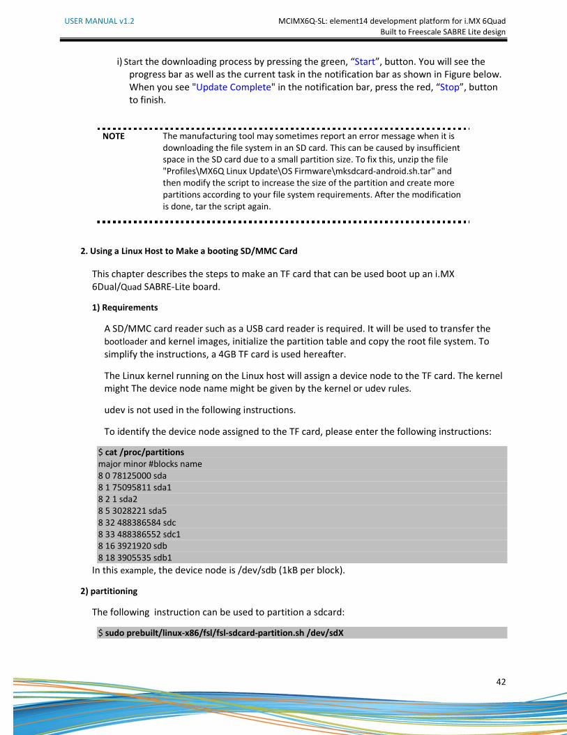
To identify the device node assigned to the TF card, please enter the following instructions:
$ cat /proc/partitions
major minor #blocks name
8 0 78125000 sda
8 1 75095811 sda1
8 2 1 sda2
8 5 3028221 sda5
8 32 488386584 sdc
8 33 488386552 sdc1
8 16 3921920 sdb
8 18 3905535 sdb1
In this example, the device node is /dev/sdb (1kB per block).
2) partitioning
The following instruction can be used to partition a sdcard:
$ sudo prebuilt/linux-x86/fsl/fsl-sdcard-partition.sh /dev/sdX
USER MANUAL v1.2 MCIMX6Q-SL: element14 development platform for i.MX 6Quad
Built to Freescale SABRE Lite design
43
NOTE 1、 The minimum size of TF card is 2G bytes
2、 The letter “x” in /dev/sdxN is the disk index from 'a' to 'z'. It may be
different on each Linux PC.
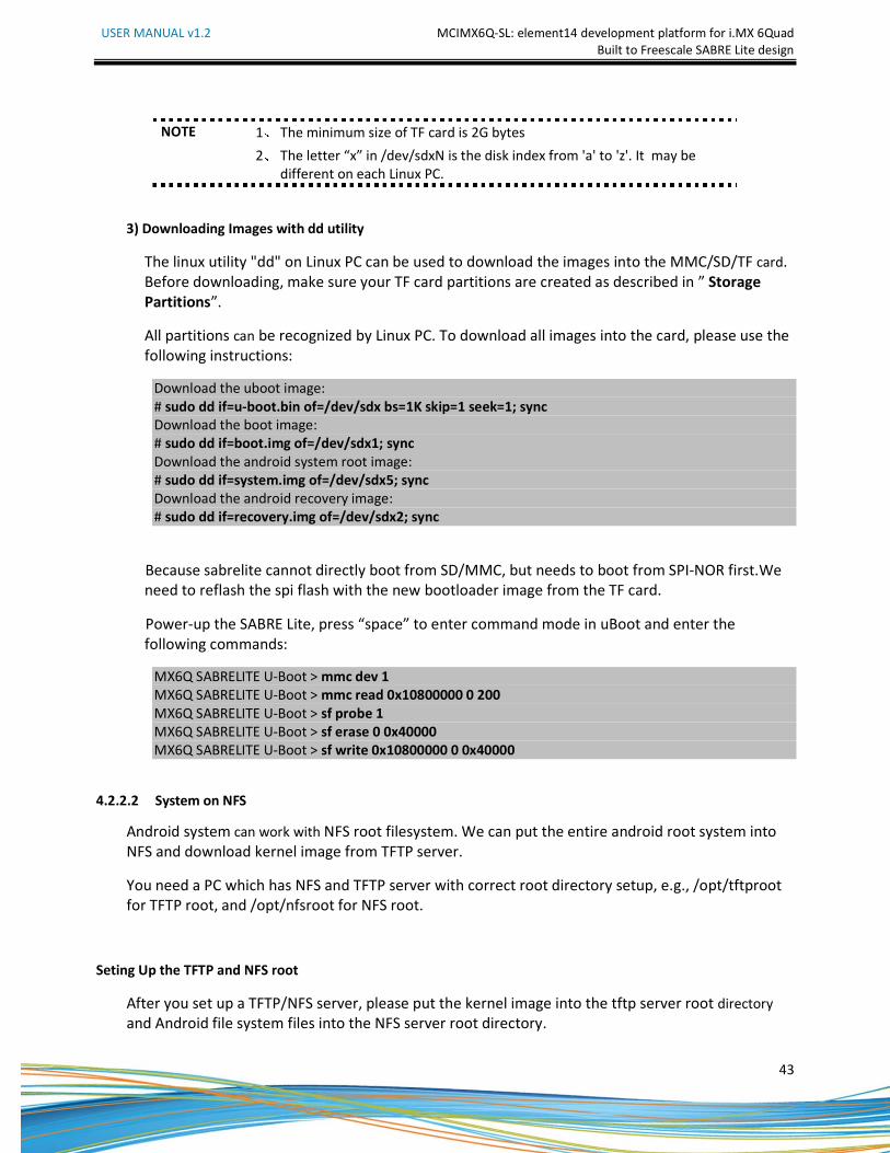
3) Downloading Images with dd utility
The linux utility "dd" on Linux PC can be used to download the images into the MMC/SD/TF card.
Before downloading, make sure your TF card partitions are created as described in ” Storage
Partitions”.
All partitions can be recognized by Linux PC. To download all images into the card, please use the
following instructions:
Download the uboot image:
# sudo dd if=u-boot.bin of=/dev/sdx bs=1K skip=1 seek=1; sync
Download the boot image:
# sudo dd if=boot.img of=/dev/sdx1; sync
Download the android system root image:
# sudo dd if=system.img of=/dev/sdx5; sync
Download the android recovery image:
# sudo dd if=recovery.img of=/dev/sdx2; sync
Because sabrelite cannot directly boot from SD/MMC, but needs to boot from SPI-NOR first.We
need to reflash the spi flash with the new bootloader image from the TF card.
Power-up the SABRE Lite, press “space” to enter command mode in uBoot and enter the
following commands:
MX6Q SABRELITE U-Boot > mmc dev 1
MX6Q SABRELITE U-Boot > mmc read 0x10800000 0 200
MX6Q SABRELITE U-Boot > sf probe 1
MX6Q SABRELITE U-Boot > sf erase 0 0x40000
MX6Q SABRELITE U-Boot > sf write 0x10800000 0 0x40000
4.2.2.2 System on NFS
Android system can work with NFS root filesystem. We can put the entire android root system into
NFS and download kernel image from TFTP server.
You need a PC which has NFS and TFTP server with correct root directory setup, e.g., /opt/tftproot
for TFTP root, and /opt/nfsroot for NFS root.
Seting Up the TFTP and NFS root
After you set up a TFTP/NFS server, please put the kernel image into the tftp server root directory
and Android file system files into the NFS server root directory.
USER MANUAL v1.2 MCIMX6Q-SL: element14 development platform for i.MX 6Quad
Built to Freescale SABRE Lite design
44
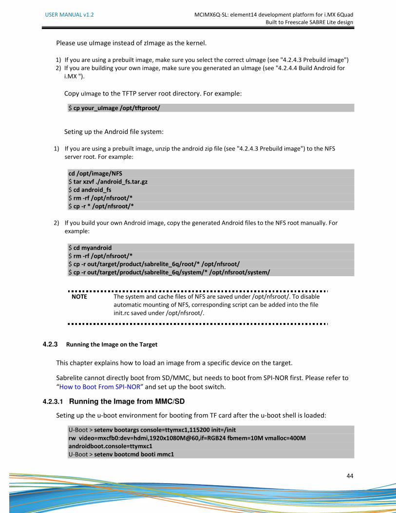
Please use uImage instead of zImage as the kernel.
1) If you are using a prebuilt image, make sure you select the correct uImage (see "4.2.4.3 Prebuild image")
2) If you are building your own image, make sure you generated an uImage (see "4.2.4.4 Build Android for
i.MX ").
Copy uImage to the TFTP server root directory. For example:
$ cp your_uImage /opt/tftproot/
Seting up the Android file system:
1) If you are using a prebuilt image, unzip the android zip file (see "4.2.4.3 Prebuild image") to the NFS
server root. For example:
cd /opt/image/NFS
$ tar xzvf ./android_fs.tar.gz
$ cd android_fs
$ rm -rf /opt/nfsroot/*
$ cp -r * /opt/nfsroot/*
2) If you build your own Android image, copy the generated Android files to the NFS root manually. For
example:
$ cd myandroid
$ rm -rf /opt/nfsroot/*
$ cp -r out/target/product/sabrelite_6q/root/* /opt/nfsroot/
$ cp -r out/target/product/sabrelite_6q/system/* /opt/nfsroot/system/
NOTE The system and cache files of NFS are saved under /opt/nfsroot/. To disable
automatic mounting of NFS, corresponding script can be added into the file
init.rc saved under /opt/nfsroot/.
4.2.3 Running the Image on the Target
This chapter explains how to load an image from a specific device on the target.
Sabrelite cannot directly boot from SD/MMC, but needs to boot from SPI-NOR first. Please refer to
“How to Boot From SPI-NOR” and set up the boot switch.
4.2.3.1 Running the Image from MMC/SD
Seting up the u-boot environment for booting from TF card after the u-boot shell is loaded:
U-Boot > setenv bootargs console=ttymxc1,115200 init=/init
rw video=mxcfb0:dev=hdmi,1920x1080M@60,if=RGB24 fbmem=10M vmalloc=400M
androidboot.console=ttymxc1
U-Boot > setenv bootcmd booti mmc1
USER MANUAL v1.2 MCIMX6Q-SL: element14 development platform for i.MX 6Quad
Built to Freescale SABRE Lite design
45
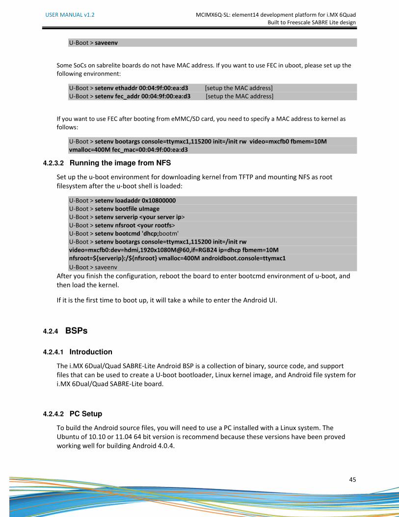
U-Boot > saveenv
Some SoCs on sabrelite boards do not have MAC address. If you want to use FEC in uboot, please set up the
following environment:
U-Boot > setenv ethaddr 00:04:9f:00:ea:d3 [setup the MAC address]
U-Boot > setenv fec_addr 00:04:9f:00:ea:d3 [setup the MAC address]
If you want to use FEC after booting from eMMC/SD card, you need to specify a MAC address to kernel as
follows:
U-Boot > setenv bootargs console=ttymxc1,115200 init=/init rw video=mxcfb0 fbmem=10M
vmalloc=400M fec_mac=00:04:9f:00:ea:d3
4.2.3.2 Running the image from NFS
Set up the u-boot environment for downloading kernel from TFTP and mounting NFS as root
filesystem after the u-boot shell is loaded:
U-Boot > setenv loadaddr 0x10800000
U-Boot > setenv bootfile uImage
U-Boot > setenv serverip <your server ip>
U-Boot > setenv nfsroot <your rootfs>
U-Boot > setenv bootcmd 'dhcp;bootm'
U-Boot > setenv bootargs console=ttymxc1,115200 init=/init rw
video=mxcfb0:dev=hdmi,1920x1080M@60,if=RGB24 ip=dhcp fbmem=10M
nfsroot=${serverip}:/${nfsroot} vmalloc=400M androidboot.console=ttymxc1
U-Boot > saveenv
After you finish the configuration, reboot the board to enter bootcmd environment of u-boot, and
then load the kernel.
If it is the first time to boot up, it will take a while to enter the Android UI.
4.2.4 BSPs
4.2.4.1 Introduction
The i.MX 6Dual/Quad SABRE-Lite Android BSP is a collection of binary, source code, and support
files that can be used to create a U-boot bootloader, Linux kernel image, and Android file system for
i.MX 6Dual/Quad SABRE-Lite board.
4.2.4.2 PC Setup
To build the Android source files, you will need to use a PC installed with a Linux system. The
Ubuntu of 10.10 or 11.04 64 bit version is recommend because these versions have been proved
working well for building Android 4.0.4.
USER MANUAL v1.2 MCIMX6Q-SL: element14 development platform for i.MX 6Quad
Built to Freescale SABRE Lite design
46
After installing Linux PC, you need to check whether you have all the necessary packages installed
for building an Android. Please refer to "Setting up your machine" on the Android web site
http://source.android.com/source/initializing.html for detailed infromation.
4.2.4.3 Prebuilt image
To test Android before building any code, use the prebuilt images under image/ and directly go to
"Download Images" and "Running the Image on the Target".
For i.MX6Q Sabrelite platform:
1) Uboot image
u-boot.bin
2) Android system images for TF card
System root: TF/system.img
Data: Not provided since it's empty.
Boot image: TF/boot.img
Recovery image: TF/recovery.img
3) Android system images for TFTP/NFS
NFS/android_fs.tar.gz
4) Kernel image for TFTP/NFS
NFS/uImage
4.2.4.4 Build Android for i.MX
1) Getting Android Source Code
$ cd ~
$ tar jxvf android-imx6-r13.3.tar.bz2
2) Building uboot Images $ cd ~/ android-imx6-r13.3/bootable/bootloader/uboot-imx
$ export ARCH=arm
$ export CROSS_COMPILE=~/android-imx6-r13.3/prebuilt/linux-x86/toolchain/arm-eabi-
4.4.3/bin/arm-eabi-
Command to build for i.MX6Q Sabrelite board is:
$ make distclean
$ make mx6q-sabrelite_android_config
$ make
"u-boot.bin"will be generated after the above instructions are executed..
The u-boot.bin has 1024KB padding at the head of the file,for example, first executable instruction is at the
offset 1KB.
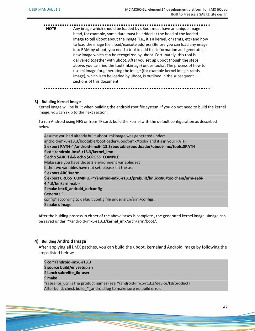
USER MANUAL v1.2 MCIMX6Q-SL: element14 development platform for i.MX 6Quad
Built to Freescale SABRE Lite design
47
NOTE Any image which should be loaded by uBoot must have an unique image
head, for example, some data must be added at the head of the loaded
image to tell uboot about the image (i.e., it's a kernel, or ramfs, etc) and how
to load the image (i.e., load/execute address).Before you can load any image
into RAM by uboot, you need a tool to add this information and generate a
new image which can be recognized by uboot. Fortunately, this tool is
delivered together with uboot. After you set up uboot though the steps
above, you can find the tool (mkimage) under tools/. The process of how to
use mkimage for generating the image (for example kernel image, ramfs
image), which is to be loaded by uboot, is outlined in the subsequent
sections of this document
3) Building Kernel Image
Kernel image will be built when building the android root file system. If you do not need to build the kernel
image, you can skip to the next section.
To run Android using NFS or from TF card, build the kernel with the default configuration as described
below:
Assume you had already built uboot. mkimage was generated under:
android-imx6-r13.3/bootable/bootloader/uboot-imx/tools/ and it's in your PATH
$ export PATH=~/android-imx6-r13.3/bootable/bootloader/uboot-imx/tools:$PATH
$ cd ~/android-imx6-r13.3/kernel_imx
$ echo $ARCH && echo $CROSS_COMPILE
Make sure you have those 2 environment variables set
If the two variables have not set, please set the as:
$ export ARCH=arm
$ export CROSS_COMPILE=~/android-imx6-r13.3/prebuilt/linux-x86/toolchain/arm-eabi-
4.4.3/bin/arm-eabi-
$ make imx6_android_defconfig
Generate ".
config" according to default config file under arch/arm/configs.
$ make uImage
After the buiding process in either of the above cases is complete , the generated kernel image uImage can
be saved under ~/android-imx6-r13.3/kernel_imx/arch/arm/boot/.
4) Building Android Image
After applying all i.MX patches, you can build the uboot, kerneland Android image by following the
steps listed below:
$ cd ~/android-imx6-r13.3
$ source build/envsetup.sh
$ lunch sabrelite_6q-user
$ make
"sabrelite_6q" is the product names (see ~/android-imx6-r13.3/device/fsl/product)
After build, check build_*_android.log to make sure no build error.
USER MANUAL v1.2 MCIMX6Q-SL: element14 development platform for i.MX 6Quad
Built to Freescale SABRE Lite design
48
For i.MX6Q Sabrelite, the following outputs are generated by default under android-imx6-
r13.3/out/target/product/sabrelite_6q :
root/: root file system (including init, init.rc, etc). Mounted at /
system/: Android system /binary/libraries. Mounted at /system
data/: Android data area. Mounted at /data
recovery/: root file system when booting in "recovery" mode. Not used directly.
boot.img: a composite image which includes the kernel zImage, ramdisk, and boot parameters.
ramdisk.img: Ramdisk image generated from "root/". Not directly used.
system.img: EXT4 image generated from "system/". Can be written to "SYSTEM" partition of SD/eMMC
card with "dd"
userdata.img: EXT4 image generated from "data/".
recovery.img: EXT4 image generated from "recovery/". Can be written to "RECOVERY" partition of
SD/eMMC card with "dd"
u-boot.bin: uboot image with padding.
For production release, the android image should be built in user mode. The user mode is different from
eng mode as shown below:
1. It has limited access due to security reason, and it lacks many debug tools.
2. It tags modules installed as user, and installs APKs&tools according to product definition files, which is in
PRODUCT_PACKAGES in device/fsl/imx6/imx6.mk
3. Set ro.secure=1, ro.debuggable=0. and disable adb.
For more information about building android. Please refer to:
http://source.android.com/source/building.html
5) Building boot.img
We use boot.img and booti as default instructions to boot rather than the uramdisk and uImage
we used before.
You can use the following instructions to generate boot.img under android environment:
$ source build/envsetup.sh
$ lunch sabrelite_6q-user
$ make bootimage
USER MANUAL v1.2 MCIMX6Q-SL: element14 development platform for i.MX 6Quad
Built to Freescale SABRE Lite design
49
5 APPENDIX
5.1 ESD PRECAUTIONS AND PROPER HANDLING PROCEDURES
• Avoid carpets in cool, dry areas. Leave development kits in their anti-static packaging until ready to
be installed.
• Dissipate static electricity before handling any system components (development kits) by touching
a grounded metal object, such as the system unit unpainted metal chassis.
• If possible, use antistatic devices, such as wrist straps and floor mats.
• Always hold a evaluation board by its edges. Avoid touching the contacts and components on the
board.
• Take care when connecting or disconnecting cables. A damaged cable can cause a short in the
electrical circuit.
• Prevent damage to the connectors by aligning connector pins before you connect the cable.
Misaligned connector pins can cause damage to system components at power-on.
• When disconnecting a cable, always pull on the cable connector or strain-relief loop, not on the
cable itself.