development of premium connection “ksbear” for ... · kawasaki steel technical ... for...
TRANSCRIPT
14 KAWASAKI STEEL TECHNICA REPORT
KAWASAKI STEEL TECHNICAL REPORT No. 47 December 2002
Development of Premium Connection “KSBEAR” for Withstanding High Compression,
High External Pressure, and Severe Bending*
Jun TakanoStaff Assistant Manager, Products Service &Development Sec.,Products Service &Development Dept.,Chita Works
Masao YamaguchiStaff Deputy Manager, Products Service &Development Sec.,Products Service &Development Dept.,Chita Works
Hidenori KunishigeTechnical SupportGroup, Chubu Office, Kawatetsu Systems,Inc.
Synopsis:
For the connection of oil well tubes used in increas-ingly severer environments, special screw jointsequipped with metal-to-metal seals, excellent in resis-tance to leakage, are generally used. However, there areincreasing in number, stricter oil well designs wheretoscrew joints of conventional properties have bacomeinapplicable any longer. Under the circumstances, oilwell screw joints, having anti-leakage property, bearablespecifically in an environment of the burdens of com-pression, external pressure and bending have becomestrongly demanded. To satisfy the above-describeddemands of customers, Kawasaki Steel has developed“KSBEAR”, substantially exceeding the properties ofconventional tubular joints. Through the uniqueadvanced design concept of a new screw thread, thedevelopment of a screw joint outstandingly surpassingthe level of API Class 1 has been achieved.
1 Introduction
In recent years, much emphasis is placed on prof-itability in oil well development and subsequent oil pro-duction, yet successive mergers between major oilcompanies and other structural changes have led theworld oil industry into fierce cost competition. Inresponse to these changes, oil wells are getting deeper,and the numbers of directional wells1) and horizontalwells are increasing. Accordingly, the condition in whichthreaded connections are used for connecting oil and gaswell tubes is becoming increasingly severe.
The method of evaluating special threaded connec-tions for oil well tubes is stipulated in API RP (Ameri-can Petroleum Institute: Recommended Practice) 5C5.Even in the highest-ranking Class 1 requirements, thestipulated test conditions are only up to the compressionof 40%PBYS (pipe body yield strength) and the leak testunder bending is not stipulated.2) On the other hand,some of the test methods recently adopted by individualoil companies take into account the actual usage envi-ronment and incorporate severe conditions such as high�����
* Originally published in Kawasaki Steel Giho, 34(2002)1, 21–28
compression of 80%PBYS and bending of 39.4°/30 m(equivalent to the bending radius of 43.7 m). Conven-tional oil well tubing threaded connections for OCTG(oil country tubular goods) can not meet these severetest conditions. Further, in view of global environmentalprotection, the ratio of gas wells is increasing, and soleakage resistance is becoming more important. There isstrong market demand for special threaded connections,premium joints which have far better performance com-pared with conventional connections. In order to meetthis demand, Kawasaki Steel has developed the premiumjoint for oil well tubes “KSBEAR” that has excellentleakage resistance under high compression, high exter-nal pressure, and severe bending. This report outlinesthe KSBEAR threaded connection, its performance eval-uation using FEA (finite element analysis), a test methodfor evaluating the connection performance, the results ofthe evaluation, and its production technology.
2 Performance Required for Oil Well TubingThreaded Connections
2.1 Leakage Resistance
Oil well tubes and their connections are subjected tovarious loads while being installed and subsequentlyused for oil production. During and also after installa-tion, tensile load acts on the connections due to the selfweight of the tubes; external pressure acts on the con-nections from the wall of the oil well; and internal pres-sure acts from within the tube due to the fluid beingproduced.
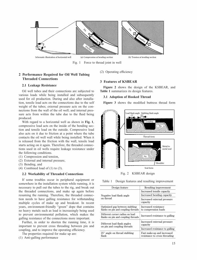
With regard to a horizontal well as shown in Fig. 1,compressive load acts on the inside of the bending sec-tion and tensile load on the outside. Compressive loadalso acts on it due to friction at a point where the tubecontacts the oil well wall while being installed. When itis released from the friction with the wall, tensile loadstarts acting on it again. Therefore, the threaded connec-tions used in oil wells require leakage resistance underthe following conditions.(1) Compression and tension,(2) External and internal pressure,(3) Bending, and(4) Combined load of (1) to (3).
2.2 Workability of Threaded Connections
If some troubles occur in peripheral equipment orsomewhere in the installation system while running, it isnecessary to pull out the tubes to the rig, and break outthe threaded connections, and make up again beforeresuming the running. Therefore, the threaded connec-tion needs to have galling resistance for withstandingmultiple cycles of make up and breakout. In recentyears, environment-friendly “green” dope that containsno heavy metals such as lead is increasingly being usedto prevent environmental pollution, which makes thegalling resistance of the connections more important.
Further, in order to shorten the running time, it isimportant to prevent cross threading between pin andcoupling, and to improve the operating efficiency.
The properties required for make up are:(1) Anti-galling performance
(2) Operating efficiency
3 Features of KSBEAR
Figure 2 shows the design of the KSBEAR, andTable 1 summarizes its design features.
3.1 Adoption of Hooked Thread
Figure 3 shows the modified buttress thread form
No. 47 December 2002 15
(b) Tension at bending section(a) Compression at bending sectionSchematic illustration of horizontal well
R
Pin
Coupling
Pin
Coupling
Friction
Fig. 1 Force to thread joint in well
Load flank angle Stabbing flank angle
Thread form
Seal form
Coupling
Pin
Coupling
Pin
Metal tometal seal
Shoulder
�5° 25°
Fig. 2 KSBEAR design
Design feature
Negative load flank angle on thread
Optimized gap between stabbingflanks on pin and coupling threads
Different corner radius on loadflanks on pin and coupling threads
Different load flank angles on pin and coupling threads
25° angle on thread stabbingflank
Resulting improvementIncreased tensile capacityIncreased bending capacity
Increased external pressurecapacity
Increased resistance to compression loads
Increased resistance to galling
Increased external pressurecapacity
Increased resistance to galling
Fast make-up and increasedresistance to cross threading
Table 1 Design features and resulting improvement

used for normal premium joints. When tensile load,bending load, and external pressure act on a connectionthat has a modified buttress thread form, these loadsgenerate a force that moves the pin thread and couplingthread away from each other in the radial direction. Inthe KSBEAR, the hooked thread form was adapted,which significantly reduced the force that moves the pinthread and coupling thread away from each other in theradial direction when tensile load, bending load, orexternal pressure acts on it.
3.2 Optimization of Gap between Stabbing Flanks
The surfaces of the threads that work as guides in theprocess of making up the pin and coupling are calledstabbing flanks, and the surfaces of the threads thatcome in contact with each other when the pin and cou-pling are tightly made up are called load flanks. Whenthe pin and coupling are made up, there is a spacebetween the stabbing flanks facing each other. When acompressive load acts on the connection, the load flanksof the pin and coupling are separated. Figure 4 showsthe results of FEA for investigating the thread conditionwhen a high compressive load of 90%PBYS acts on theconnection. The figure shows that the stabbing flankscontacting each other carry the compressive stress in theKSBEAR thread. Conversely in the modified buttressthread, there is a wide gap between the stabbing flanksof the pin and coupling threads and, even when a highcompressive load of 90%PBYS acts, the stabbing flanksdo not come in contact with each other. Therefore, allthe stress in the axial direction of the tube needs to be
carried by the sealing section and torque shoulder, andplastic deformation is caused there. When a tensile loadis applied after compression, the contact pressure at thesealing section is lowered, resulting in leakage. In con-trast, in the KSBEAR, the gap between the stabbingflanks is optimized so that the stabbing flanks come intocontact with each other when high compression isapplied. Approximately 19% of the total compressiveload is carried by the stabbing flanks in contact witheach other (in case of 80 ksi 7˝ � 32.0 lb/ft). Accord-ingly, the loads acting on the shoulder and sealing sec-tion are reduced and plastic deformation at thesesections is significantly suppressed. As a result, the leak-age resistance is markedly improved when a tensile loadis applied after compression.
3.3 Optimization of Corner Radius of Load Flank of Pin Thread
As stated in Section 3.1, the hooked thread offersgood leakage resistance. However, galling tends to occurwhen the threads are being made up, particularly at aposition where stress concentrates: that is, the upper por-tion of the load flank of the pin thread. In the KSBEAR,the radius of the upper corner of the load flank wasmade larger to prevent stress concentration that causesgalling. As a result, the KSBEAR has excellent gallingresistance.
3.4 Optimization of Load Flank Angles of Pin and Coupling Threads
As stated in Section 3.3, stress tends to concentrate atthe crest of the hooked pin thread and cause breakagethere. In the KSBEAR, the angle of the load flank of thepin thread against that of the coupling thread was modi-fied so as to make the stress concentrate at the lowerportion of the pin thread that has the highest strength.Figure 5 shows the stress distribution obtained by FEA.The galling resistance was further improved.
3.5 Stabbing Angle of 25°
In the running of connection at an oil well, a pipelifted up is lowered and a pin end of the pipe is insertedinto a coupling. If cross threading occurs in this process,
16 KAWASAKI STEEL TECHNICAL REPORT
Load flank angle Stabbing flank angle3° 10°
Coupling
Pin
Fig. 3 Form of modified buttress thread
Compression 0 TensionCompression 0 Tension
(b) KSBEAR thread(a) Modified buttress thread
Fig. 4 Axial stress distribution by FEA at 90%PBYS compression (13 Cr-80 7˝ � 29.0 lb/ft)

the work efficiency is decreased significantly. Therefore,the stabbing angle was increased to 25° in the KSBEARfrom 10° in the modified buttress thread to improve themake-up efficiency.
4 Development of FEA Models
FEA is an effective means to estimate the amount ofelasto-plastic deformation in the threaded connectionsand the contact pressure at the sealing sections in thephysical test quantitatively. However, conventional FEAmodels cannot simulate results of the physical test car-ried out under severe conditions not previously experi-enced, such as extremely high compression, highexternal pressure, and severe bending. Therefore, twomodels were newly developed as described below.
4.1 Successive Make-up Model
Leakage tests of threaded connections are generallyperformed after multiple cycles of make-up and break-out of the threads. It is necessary to evaluate the amountof strain generated in the axial and radial directions ofthe tube when multiple cycles of make-up and break-outare successive performed. Conventional FEA modelscan only be used to analyze a single make-up. In thenewly developed model, imaginary thermal strain isgiven in a region where the coupling is located as shownin Fig. 6, and allowed to expand and shrink in the axialdirection in order to model the thread make-up andbreak-out. Figure 7 compares the values of axial strainand hoop strain calculated by FEA and with those mea-sured in the experiment. Evaluated points at make-up areshown in Fig. 8. The values calculated using the newFEA model and observed values are in good agreement,thus confirming the high accuracy of the new model.
4.2 Bending Model
Almost no FEA has been carried out for analyzing theresults of bending tests so far. A bending load is axiallynon-symmetrical; therefore conventional axially sym-metrical models are not applicable. For analyzing bend-ing behavior, a 3-dimensional model is needed, butdeveloping a 3-dimensional model is too laborious andthe calculation time is too long, so it is not a practicalsolution. Therefore, a new bending model was con-
No. 47 December 2002 17
Compression 0 Tension
Fig. 5 Axial stress distribution by FEA at make-up(KSBEAR)
OverlapOverlap
Initial
Contact
Overlap
1st step
Expansion in axial direction
2nd step
Contact
Contact
Shrinkage in axial direction
3rd step
Fig. 6 Make-up model in FEA model

structed employing axially symmetrical elements thatpermit non-linear, axially non-symmetrical deformation;hence 3-dimensional analysis can be performed using anaxially symmetrical model. These elements have inde-pendent nodal points in the hoop direction. Nodal pointdisplacement is calculated from the equation of equilib-rium of force at each nodal point. Displacement at anarbitrary point is given by Eq. (1).
ur M�uz�� � Hm (g, h) �uθ
m�1
P�1 urmp
P 0�� Rp (θ)�uzmp�� � sin pθ� 0 �� · · · (1)
p�1 0 p�1 uθmp
Where urmp, uz
mp, uθmp are respectively the displace-
ment component in the radial direction, axial directionand hoop direction at θ � π(p-1)/P; Hm(g, h) is theinterpolation function in the r-z plane at θ � 0; Rp(θ) isthe interpolation function in the hoop direction; M is thenumber of nodal points in the element; and P is thenumber of nodal planes in the hoop direction.
The bending load is the bending moment equivalentto the bending amount that is given at the end of the pin.Figure 9 shows the results of FEA calculation. Figure10 compares the results of calculation using the newlyproposed FEA model and the theoretical values. The twosets of values are in good agreement.
5 Performance Evaluation Test of KSBEAR
The method for evaluating threaded connections foroil well use is stipulated in API RP 5C5. However, inrecent years, customers are increasingly requesting addi-tional bending tests and higher compression tests.
The performance evaluation test that a certain majoroil company requested is introduced below as well as theresults of the tests performed on the KSBEAR.
18 KAWASAKI STEEL TECHNICAL REPORT
0.004
0.002
0
�0.002
�0.004
Observed
FEAA
xial
str
ain
1 2 3 4
Number of make-ups
Axial strain at point A
0.004
0.002
0
�0.002
�0.004
Observed
FEA
Hoo
p st
rain
1 2 3 4
Number of make-ups
Hoop strain at point A
0.004
0.002
0
�0.002
�0.004
Observed
FEA
Axi
al s
trai
n
1 2 3 4Number of make-ups
Axial strain at point B
0.004
0.002
0
�0.002
�0.004
Observed
FEA
Hoo
p st
rain
1 2 3 4Number of make-ups
Hoop strain at point B
Fig. 7 Change in strain by number of make-ups
B
A
5.0 mm
127.0 mm
Fig. 8 Evaluation point for stress at make-up
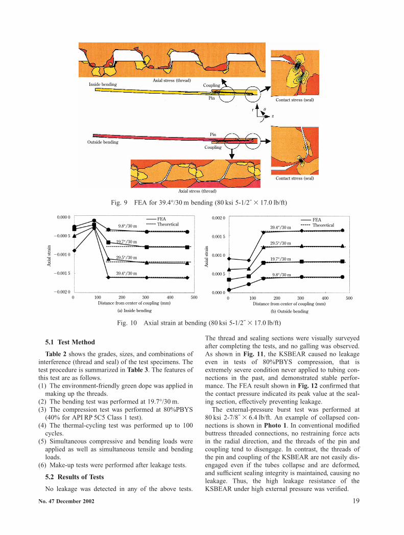
5.1 Test Method
Table 2 shows the grades, sizes, and combinations ofinterference (thread and seal) of the test specimens. Thetest procedure is summarized in Table 3. The features ofthis test are as follows.(1) The environment-friendly green dope was applied in
making up the threads.(2) The bending test was performed at 19.7°/30 m.(3) The compression test was performed at 80%PBYS
(40% for API RP 5C5 Class 1 test).(4) The thermal-cycling test was performed up to 100
cycles.(5) Simultaneous compressive and bending loads were
applied as well as simultaneous tensile and bendingloads.
(6) Make-up tests were performed after leakage tests.
5.2 Results of Tests
No leakage was detected in any of the above tests.
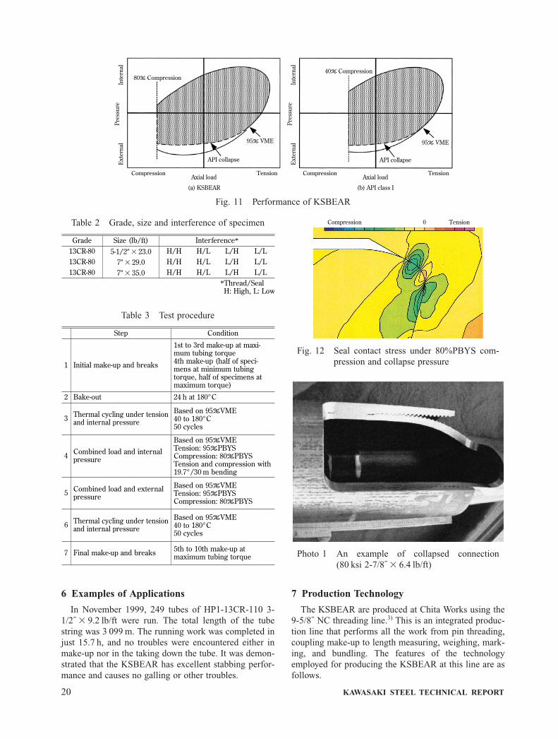
The thread and sealing sections were visually surveyedafter completing the tests, and no galling was observed.As shown in Fig. 11, the KSBEAR caused no leakageeven in tests of 80%PBYS compression, that isextremely severe condition never applied to tubing con-nections in the past, and demonstrated stable perfor-mance. The FEA result shown in Fig. 12 confirmed thatthe contact pressure indicated its peak value at the seal-ing section, effectively preventing leakage.
The external-pressure burst test was performed at80 ksi 2-7/8˝ � 6.4 lb/ft. An example of collapsed con-nections is shown in Photo 1. In conventional modifiedbuttress threaded connections, no restraining force actsin the radial direction, and the threads of the pin andcoupling tend to disengage. In contrast, the threads ofthe pin and coupling of the KSBEAR are not easily dis-engaged even if the tubes collapse and are deformed,and sufficient sealing integrity is maintained, causing noleakage. Thus, the high leakage resistance of theKSBEAR under high external pressure was verified.
No. 47 December 2002 19
Contact stress (seal)
Contact stress (seal)
rz
θ
Inside bending
Outside bending
Coupling
Pin
Pin
Coupling
Axial stress (thread)
Axial stress (thread)
Fig. 9 FEA for 39.4°/30 m bending (80 ksi 5-1/2˝ � 17.0 lb/ft)
0.002 0
0.001 5
0.001 0
0.000 5
0.000 0
FEATheoretical39.4°/30 m
29.5°/30 m
19.7°/30 m
9.8°/30 m
0 100 200 300 400 500Distance from center of coupling (mm)
(b) Outside bending
Axi
al s
trai
n
0.000 0
�0.000 5
�0.001 0
�0.001 5
�0.002 0
FEATheoretical
0 100 200 300 400 500Distance from center of coupling (mm)
(a) Inside bending
Axi
al s
trai
n
9.8°/30 m
19.7°/30 m
29.5°/30 m
39.4°/30 m
Fig. 10 Axial strain at bending (80 ksi 5-1/2˝ � 17.0 lb/ft)
6 Examples of Applications
In November 1999, 249 tubes of HP1-13CR-110 3-1/2˝ � 9.2 lb/ft were run. The total length of the tubestring was 3 099 m. The running work was completed injust 15.7 h, and no troubles were encountered either inmake-up nor in the taking down the tube. It was demon-strated that the KSBEAR has excellent stabbing perfor-mance and causes no galling or other troubles.
7 Production Technology
The KSBEAR are produced at Chita Works using the9-5/8˝ NC threading line.3) This is an integrated produc-tion line that performs all the work from pin threading,coupling make-up to length measuring, weighing, mark-ing, and bundling. The features of the technologyemployed for producing the KSBEAR at this line are asfollows.
20 KAWASAKI STEEL TECHNICAL REPORT
Compression TensionAxial load
(b) API class I
API collapse
95% VME
40% Compression
Inte
rnal
Ext
erna
lPr
essu
re
Compression TensionAxial load
(a) KSBEAR
API collapse
95% VME
80% Compression
Inte
rnal
Ext
erna
lPr
essu
re
Fig. 11 Performance of KSBEAR
Step Condition
1 Initial make-up and breaks
1st to 3rd make-up at maxi-mum tubing torque4th make-up (half of speci-mens at minimum tubingtorque, half of specimens atmaximum torque)
2 Bake-out 24 h at 180°C
3 Thermal cycling under tensionand internal pressure
Based on 95%VME40 to 180°C50 cycles
4 Combined load and internal pressure
Based on 95%VMETension: 95%PBYSCompression: 80%PBYSTension and compression with19.7°/30 m bending
5 Combined load and externalpressure
Based on 95%VMETension: 95%PBYSCompression: 80%PBYS
6
7
Thermal cycling under tensionand internal pressure
Final make-up and breaks
Based on 95%VME40 to 180°C50 cycles
5th to 10th make-up atmaximum tubing torque
Table 3 Test procedure
Compression 0 Tension
Fig. 12 Seal contact stress under 80%PBYS com-pression and collapse pressure
Photo 1 An example of collapsed connection(80 ksi 2-7/8˝ � 6.4 lb/ft)
Grade Size (lb/ft) Interference*
13CR-80 5-1/2� � 23.0 H/H H/L L/H L/L13CR-80 7� � 29.0 H/H H/L L/H L/L13CR-80 7� � 35.0 H/H H/L L/H L/L
*Thread/SealH: High, L: Low
Table 2 Grade, size and interference of specimen

7.1 Threading by Tool-rotating NC Machine
There are two types of threading machines: pipe-rotating type and tool-rotating type. The two types arecompared in Table 4. The pipe-rotating type commonlyused has one chaser, and has a large space around thepipe being cut, which leads to excellent tip disposability.However, it performs a designated amount of cutting at atime, and takes longer to complete the threading work,which results in lower productivity. It also has a disad-vantage in cutting a hooked thread of KSBEAR,because, for each cutting operation, the cutting trajec-tory needs to be shifted to the pipe’s axial direction (z-axis direction) as well as to the radial direction (x-axisdirection).
On the other hand, the tool-rotating type employed inthis threading line uses four chasers positioned aroundthe pipe for cutting threads. Three crests in each chaserhave a phase delayed by one-quarter of a cycle from thecorresponding crest in the preceding chaser, and the cor-responding crests become higher and wider in the orderof cutting. The last crest finishes the cutting work. Thetool block moves in the pipe’s axial direction while thechasers rotate around the pipe. The tool-rotating typecan quickly cut a thread that requires a complex cuttingmethod such as a hooked thread. However, its tip dis-posability is inferior because multiple chasers simulta-neously perform cutting work, and the crests of thechasers tend to be broken off. Kawasaki Steel has over-come these shortcomings by improving the configura-tion of the tool block and so on.
7.2 Seal Portion Cutting by Formed Tool
The seal portion is generally cut by the single-pointcutting method. The threading machine in this lineemploys the formed tool for cutting the seal portion.Figure 13 compares the cutting methods of the seal por-tion by single-point cutting and formed tool cutting. Inthe single-point cutting, the cutting speed needs to bereduced for cutting the seal portion because a high-qual-ity surface finish is required, which prolongs therequired cutting time. In the formed tool cutting, ahighly accurate seal shape can be obtained in a muchshorter time.
7.3 Fully Automatic Thread Inspection by Optical Gauging System
A fully automatic optical gauging system is employedin this threading line, as shown in Fig. 14. The feature ofthis system is that the thread form is recognized by anoptical, non-contact method. In order to establish consis-tency of measured values with conventional contact-typegauging systems, a virtual probe system was adopted,which simulates the contact between the thread formobtained by the optical system and the probe in the con-
No. 47 December 2002 21
Schematicillustration
Chaser arrangementand chaser form
Cutting order
Pipe-rotating type threading machine Tool-rotating type threading machine
Front turretRear turret
Pipe endPipe chuck
Chaser
Pipe
1234
5678
9101112: Finish
ZX
Tool block
Pipe end
Pipe chuck
Internal pipesupport
ABCD
ChaserB
D
PipeA
C
B3B2B1 C3C2C1 D3D2D1A1 A3A2
A1B1C1D1
A2B2C2D2
A3B3C3D3
Table 4 Comparison in threading machine between pipe-rotating type and tool-rotating type
ImprovedConventional
Fig. 13 Cutting method of seal portion

ventional gauging system. This system can quickly per-form the measurement, and makes 100% inspection pos-sible without lowering the productivity of the line.
8 Conclusion
The KSBEAR is a premium threaded connection foroil well tubes used in severe environments and wasdeveloped based on a new concept different from thatfor conventional connections. The following results wereachieved.
(1) Plastic deformation at the seal portion under thehigh compressive load was suppressed by optimizingthe gap between the stabbing flanks.
(2) The hooked thread’s tendency to cause galling wasovercome by changing the corner radius of the loadflank.
(3) The galling resistance was further improved by opti-mizing the load flank angles of both the pin and cou-pling.
(4) FEA models were developed for analyzing theeffects of multiple cycles of successive make-up andbreak-out the connections.
(5) Also, FEA models were proposed for analyzing theeffects of bending.
(6) Performance evaluation tests confirmed that theKSBEAR causes no leakage even under the compres-sion of 80%PBYS and bending of 19.7°/30 m, andmarkedly outperforms the API Class 1 performancerequirements.
(7) A new technology was developed for quickly cuttinga thread that requires a complicated cutting methodsuch as a hooked thread using a tool-rotating typethreading machine.
References
1) Technology Research Center, Japan National Oil Corp.:“Sekiyu Kogyo no Gijutsu Koza”, (1983), 269, [Sekiyu KeizaiJournal Sya]
2) American Petroleum Institute: “Recommended Practice forEvaluation Procedures for Casing and Tubing Connections”,(1996), 45
3) K. Shimamoto, J. Takano, and K. Takahashi: Kawasaki SteelGiho, 29(1997)2, 71
22 KAWASAKI STEEL TECHNICAL REPORT
Data processor boardLinear CCD
Proceeding direction
of optical system
Pinthread
Halogen lamp
Fig. 14 Schematic illustration of optical gaugingsystem