development of portable x-band linac x …goneri.nuc.berkeley.edu/jiw-ntas/student...
TRANSCRIPT
Joint International Workshop: Nuclear Technology and Society – Needs for Next Generation Berkeley, California, January 6-8, 2008, Berkeley Faculty Club, UC Berkeley Campus
DEVELOPMENT OF PORTABLE X-BAND LINAC X-RAY SOURCE FOR NON-DESTRUCTIVE TESTING
Tomohiko Yamamoto, Takuya Natsui, Fumito Sakamoto and Mitsuru Uesaka Nuclear Professional School, Department of Engineering
The University of Tokyo 2-22 Shirakata - Shirane, Tokai, Naka, Ibaraki, JAPAN 319-1188
[email protected]; [email protected]; [email protected]; [email protected]
Naoki Nakamura, Eiji Tanabe Accuthera Inc.
2-7-6, Kurigi, Asao, Kawasaki, Kanagawa, JAPAN, 215-0033 [email protected]; [email protected]
ABSTRACT
We are developing a portable X-ray non-destructive testing (NDT) system using 9.4GHz X-band linear accelerator (linac) with 250kW magnetron. This X-ray source’ energy is less than 950 keV for Japanese regulation. The 950 keV X-band linac X-ray generator is under development for corrosion wastage of tubes and condition based maintenance of impeller pumps. We have chosen the 250kW magnetron so that the RF heat loss is remarkably reduced. This design yields compactness and portable. This system consists of the X-band magnetron, modulator, thermionic 20kV electron gun, X-band linac, and metal target of X-ray generation. We aim that X-ray spot size is less than 1mm. We designed the linac structure of the π mode at low energy parts and the π/2 mode at high energy parts, and analyzed the electromagnetic field by SUPERFISH and the electron beam dynamics by GPT. We finished cold test, RF aging and electron beam emission. Now, we are performing electron accelerating test and X-ray generation. Details of the total system and demonstration experiment are presented. Key Words: X-band linac X-ray source, Non-destructive test, Condition based maintenance
1. INTRODUCTION Generally, non-destructive testing (NDT) is carried out by using ultrasonic, radiation, neutron, eddy-current, and X-ray. Nondestructive testing by using X-ray is particularly the most useful technique to inspect with higher resolution. We can especially evaluate corroded pipes of petrochemical complex, nuclear- and thermal-power plants by the high energy X-ray NDT system. General X-ray NDT system is based on the S-band linear accelerator (linac), but it is rather large and the electron beam spot size and the spatial resolution are about 3 mm. On the other hand, we design a mobile “Suit-case-sized” X-band 950keV linac for NDT applications. The NDT system with X-band linac uses 1 MW magnetron, where the RF heat loss is serious.

Tomohiko Yamamoto, et al.
Joint International Workshop: Nuclear Technology and Society – Needs for Next Generation Berkeley, California, January 6-8, 2008, Berkeley Faculty Club, UC Berkeley Campus
2/6
We can inspect inner imperfections of many remarkable industrial products if we use this portable NDT system.
2. THE DETAIL OF X-RAY SOURCE SYSTEM
2.1. Schematic View of X-ray Non-destructive Testing System We have developed a compact X-ray NDT system using 9.4 GHz X-band linac driven by a tunable 250 kW magnetron. Fig.1 is the schematic illustration of our compact NDT system. Instead of a large 1.5MW magnetron conventionally used in 1 MeV X-band linacs, we have chosen a low power, marine radar magnetron to significantly reduce system cost and enhance portability. Our system consists of the magnetron, microwave components, pulse modulator,thermionic 20 kV electron gun, X-band linac, target for X-ray generation, and control system.The total system size consists of two boxes of 50 cm x 30 cm x 30 cm for power supply, 50 cm x 30 cm x 30 cm for magnetron, linac, cooling system and metal target of X-ray generation. The operation temperature of the system is 35 degree.
Gun Heater Supply
PowerSupply
Heater
RF WindowGun HV
Magnetron HV
Magnetron Heater Supply
TargetElectron
Gun
Accelerator Tube
AFC
Circulator
DummyLoad
CompressedZone by N2
RF Window
e- Beam
X-ray
Temperature 35
Gun Heater Supply
PowerSupply
Heater
RF WindowGun HV
Magnetron HV
Magnetron Heater Supply
TargetElectron
Gun
Accelerator Tube
AFC
Circulator
DummyLoad
CompressedZone by N2
RF Window
e- Beam
X-ray
Temperature 35
Figure 1. Schematic illustration of compact X-ray generator
2.2. X-ray Non-destructive Testing Applications The 950 keV X-band linac X-ray generator is under development for corrosion wastage of tubes and condition based maintenance of impeller pumps. We can carry out on-site evaluation of
DEVELOPMENT OF PORTABLE X-BAND LINAC X-RAY SOURCE FOR NON-DESTRUCTIVE TESTING
Joint International Workshop: Nuclear Technology and Society – Needs for Next Generation Berkeley, California, January 6-8, 2008, Berkeley Faculty Club, UC Berkeley Campus
3/6
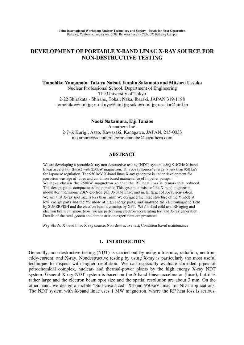
industrial products at various plants and petrochemical complexes with this NDT system,. Considering X-ray energy and spot size, this system can evaluate corrosion and wastage of tube. As you can see Table 1, the corrosion and wastage size are more than 1mm.
Table I. Objects of evaluation
< 1> 1> 1Size (mm)Small crackWastageCorrosion
Flaw
< 1> 1> 1Size (mm)Small crackWastageCorrosion
Flaw
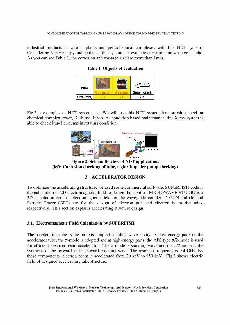
Fig.2 is examples of NDT system use. We will use this NDT system for corrosion check at chemical complex tower, Kashima, Japan. As condition based maintenance, this X-ray system is able to check impeller pump in rotating condition.
Corrosion and hole
�
X-ray
1-4m
20-8
0m
Corrosion and hole
�
X-ray
1-4m
20-8
0m
Figure 2. Schematic view of NDT applications
(left: Corrosion checking of tube, right: Impeller pump checking)
3. ACCELERATOR DESIGN To optimize the accelerating structure, we used some commercial software. SUPERFISH-code is the calculation of 2D electromagnetic field to design the cavities. MICROWAVE STUDIO is a 3D calculation code of electromagnetic field for the waveguide coupler. D-GUN and General Particle Tracer (GPT) are for the design of electron gun and electron beam dynamics, respectively. This section explains accelerating structure design.
3.1. Electromagnetic Field Calculation by SUPERFISH The accelerating tube is the on-axis coupled standing-wave cavity. At low energy parts of the accelerator tube, the π-mode is adopted and at high-energy parts, the APS type π/2-mode is used for efficient electron beam acceleration. The π-mode is standing wave and the π/2-mode is the synthesis of the forward and backward traveling wave. The resonant frequency is 9.4 GHz. By these components, electron beam is accelerated from 20 keV to 950 keV. Fig.3 shows electric field of designed accelerating tube structure.

Tomohiko Yamamoto, et al.
Joint International Workshop: Nuclear Technology and Society – Needs for Next Generation Berkeley, California, January 6-8, 2008, Berkeley Faculty Club, UC Berkeley Campus
4/6
Figure 3. Electric field of accelerator tube by SUPERFISH
3.2. Beam Dynamics Simulation by GPT We could calculate beam energy shift by GPT, and confirmed this accelerator structure is effective. The energy density and histogram are shown in Fig.4
N(nmacro) = 1920
0.0 0.2 0.4 0.6 0.8 1.0 1.2 1.4 1.6 1.8 2.0GPT Energy [MeV]
0
500
1000
1500
2000
coun
t
Figure 4. Beam dynamics simulation by GPT (left: energy density, right: histogram)
4. EXEPERMENT RESULT We completed the measurement of resonant frequency and axial electromagnetic fields using the bead-pull method. We have also checked the design parameters. Now, the whole system included beam diagnostic section is under construction at Nuclear Professional School, the University of Tokyo. Fig.6 is the photograph of X-band linac tube.
e- gun
RF Window
e- Beam
Figure 6.Photo of accelerator tube
Effective beam
DEVELOPMENT OF PORTABLE X-BAND LINAC X-RAY SOURCE FOR NON-DESTRUCTIVE TESTING
Joint International Workshop: Nuclear Technology and Society – Needs for Next Generation Berkeley, California, January 6-8, 2008, Berkeley Faculty Club, UC Berkeley Campus
5/6
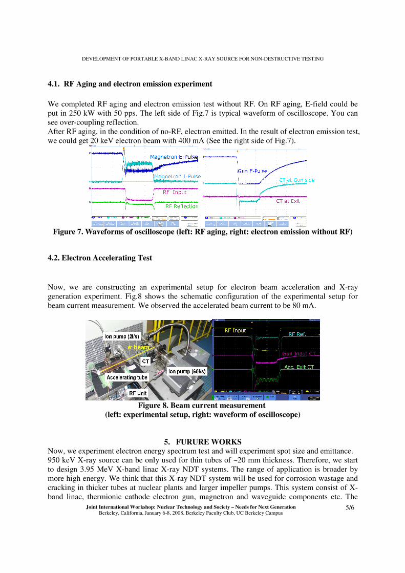
4.1. RF Aging and electron emission experiment We completed RF aging and electron emission test without RF. On RF aging, E-field could be put in 250 kW with 50 pps. The left side of Fig.7 is typical waveform of oscilloscope. You can see over-coupling reflection. After RF aging, in the condition of no-RF, electron emitted. In the result of electron emission test, we could get 20 keV electron beam with 400 mA (See the right side of Fig.7).
Figure 7. Waveforms of oscilloscope (left: RF aging, right: electron emission without RF)
4.2. Electron Accelerating Test Now, we are constructing an experimental setup for electron beam acceleration and X-ray generation experiment. Fig.8 shows the schematic configuration of the experimental setup for beam current measurement. We observed the accelerated beam current to be 80 mA.
Figure 8. Beam current measurement
(left: experimental setup, right: waveform of oscilloscope)
5. FURURE WORKS Now, we experiment electron energy spectrum test and will experiment spot size and emittance. 950 keV X-ray source can be only used for thin tubes of ~20 mm thickness. Therefore, we start to design 3.95 MeV X-band linac X-ray NDT systems. The range of application is broader by more high energy. We think that this X-ray NDT system will be used for corrosion wastage and cracking in thicker tubes at nuclear plants and larger impeller pumps. This system consist of X-band linac, thermionic cathode electron gun, magnetron and waveguide components etc. The

Tomohiko Yamamoto, et al.
Joint International Workshop: Nuclear Technology and Society – Needs for Next Generation Berkeley, California, January 6-8, 2008, Berkeley Faculty Club, UC Berkeley Campus
6/6
3.95 MeV X-band linac structure is adopted side-coupled structure for higher electric field works out. This structure is more effective acceleration than 950 keV Linac with alternating periodic structure. We adopt 1.3 MW magnetron for RF source. This accelerator system is ~30cm long. The beam current is ~150 mA, and X-ray dose rate is 10 Gy@1m/500 pps.
6. CONCLUSIONS We have designed and developed a compact, non-destructive X-ray evaluation system using the 9.4 GHz X-band linac with a 250 kW magnetron. By using X-band linac and low power magnetron, the accelerator length becomes shorter, and the RF heat loss is remarkably reduced. Therefore, the cooling system becomes smaller, and the total system size becomes more compact and portable. With this NDT system, we can carry out on-site evaluation of industrial products at various plants and petrochemical complexes.
ACKNOWLEDGMENTS The part of present study has been performed under the program of KEK to support universities in accelerator developments, and Local Area Consortium Research and Development Project of Ministry of Economy, Trade and Industry. A part of application study has been performed under Global COE Program “Nuclear Education and Research Initiative.”
REFERENCES 1. Tomohiko Yamamoto et al., “Development of Portable 950 keV X-band Li c for On-
site Nondestructive Evaluation,” Proceeding of Eighth International Topical Meeting on Nuclear Application and Utilization of Accelerators (AccApp'07), Pocatello, USA, July 29-Aug. 2,pp(2007).
2. Takuya Natsui et al., “Development of Nondestructive Testing System by 9.4 GHz X-band 950keV Electron Linac,” Proceeding of Particle Accelerator Conference '07, Albuquerque, USA, Dates of Meeting, THPMN031 (2007).
3. Tomohiko Yamamoto et al., “Compact 950 keV X-band (9.4GHz) Linac X-ray Source for On-site Non-destructive Evaluation,” Proceeding of Eighth IEEE International Vacuum Electronics Conference (IVEC2007), Kitakyushu, JAPAN, May13-17, pp.443-444 (2007).
4. Tomohiko Yamamoto et al., “Design of 9.4GHz 950keV X-band Linac for Nondestructive Testing,” Proceeding of European Particle Accelerator Conference '06, Edinburgh, UK, Dates of Meeting, WEPCH182 (2006).
5. SUPERFISH: Los Alamos National Laboratory, http://laacg1.lanl.gov/laacg/services/download_sf.phtml
6. MICROWAVE STUDIO: CST Inc. Germany, http://www.cst.com/ 7. D-GUN: Russian Academy of Science, http://www.vlepp.serpukhov.su/engl/dgun.html 8. General Particle Tracer (GPT): Pulsar Physics, Netherlands, http://www.pulsar.nl/gpt/