development of polyvinylidene fluoride ...umpir.ump.edu.my/id/eprint/7065/1/cd7201.pdf · pengimbas...
TRANSCRIPT

i
DEVELOPMENT OF POLYVINYLIDENE FLUORIDE -
POLYDIMETHYLSILOXANE (PVDF-PDMS) THIN FILM
COMPOSITE (TFC) MEMBRANE FOR CO2/ N2 GAS SEPARATION
ABDUL KARIM BIN SHAIKH ABDUL NASIR
A thesis submitted to the Faculty of Chemical and Natural Resources Engineering in
partial fulfillment of the requirement for the Degree of Bachelor of Engineering in
Chemical Engineering (Gas Technology)
Faculty of Chemical and Natural Resources Engineering
Universiti Malaysia Pahang
FEBRUARY 2013

vi
DEVELOPMENT OF POLYVINYLIDENE FLUORIDE –
POLYDIMETHYLSILOXANE (PVDF-PDMS) THIN FILM COMPOSITE
(TFC) MEMBRANE FOR CO2/ N2 GAS SEPARATION
ABSTRACT
The objectives of this research is to develop of Polyvinylidenefluoride
(PVDF) – Polydimethylsiloxane (PDMS) Thin Film Composite (TFC) and study the
membrane performance for gas separation of CO2/N2. The support PVDF membranes
were prepared by dry wet phase inversion with 15 %w/v of PVDF and 82%w/v of
N-methyl-2-pyrrolidone (NMP) as solvent and 3%w/v of water as non-solvent.
Polydimethylsiloxane (PDMS) was coated on the support membrane to produce a
composite membrane using a dip coating method using 10, 15, 20 ratio of PDMS/n-
hexane. Scanning Electron Microscopy (SEM) and Fourier Transform Infrared
(FTIR) spectroscopy, to determine chemical properties and physical of membrane.
The selectivity of CO2/N2 gas was determined by gas permeation test. From the
results, the high selectivity of the membrane behavior selected as the new
membranes for gas separation membranes future. After tested by gas permeation test,
the result of development PVDF-PDMS-TFC membrane gave excellent performance
in separating CO2/N2 with higher selectivity and permeability.
vii
PENGHASILAN POLIVINYLIDENE FLUORIDA -
POLIDIMETILSILOKSAN (PVDF-PDMS) KOMPOSIT FILEM NIPIS (TFC)
MEMBRAN UNTUK PENGASINGAN GAS CO2/ N2
ABSTRAK
Objektif kajian ini adalah untuk menghasilkan Polyvinylidene Fluoride
(PVDF) - Polydimethylsiloxane (PDMS) Filem Nipis Komposit (TFC) dan mengkaji
prestasi membran untuk pemisahan gas CO2/N2. Sokongan PVDF membran telah
disediakan oleh penyongsangan fasa basah kering dengan 15% w / v PVDF dan 82%
w / v N-metil-2-pyrrolidone (NMP) sebagai pelarut dan 3% w / v air sebagai bukan
pelarut . Polydimethylsiloxane (PDMS) telah disalut pada membran sokongan untuk
menghasilkan membran komposit menggunakan kaedah celup salutan menggunakan
10, 15, 20 nisbah PDMS / n-heksana. Pengimbas Mikroskopi Elektron (SEM) dan
Fourier Spektroskopi Radiasi Infra-merah (FTIR), untuk menentukan sifat-sifat
kimia dan fizikal membran. Kepilihan CO2/N2 gas telah ditentukan oleh ujian
penyerapan gas. Daripada keputusan, kepilihan yang tinggi tingkah laku membran
dipilih sebagai membran baru membran pemisahan gas masa depan. Selepas diuji
dengan ujian penyerapan gas, hasil membran pembangunan PVDF-PDMS-TFC
memberikan prestasi yang cemerlang dalam memisahkan CO2/N2 dengan pemilihan
yang lebih tinggi dan kebolehtelapan.
viii
TABLE OF CONTENT
SUPERVISOR’S DECLARATION ii
STUDENT’S DECLARATION iii
DEDICATION iv
ACKNOWLEDGEMENT v
ABSTRACT vi
ABSTRAK vii
LIST OF TABLES xi
LIST OF FIGURES xii
LIST OF EQUATION xv
LIST OF ABBREVIATIONS xvi
LIST OF SYMBOLS xvii
CHAPTER 1 INTRODUCTION
1.1 Background of The Research 1
1.2 Problem Statement 2
1.3 Research Objectives 3
1.4 Scopes of Research Proposed 3
1.5 Rationale And Significant 4
CHAPTER 2 LITERATURE REVIEW
2.1 Background Of Membranes 5
2.2 Membrane Module 6
2.2.1 Plate And Frame 7
2.2.2 Tubular 7
2.2.3 Hollow Fiber 9
2.2.4 Spiral Wound 10
2.3 Membrane Material 11
2.4 Structure of Membrane 13
2.5 Process And Application of Membrane 15
2.6 Membrane Fouling 18
2.7 Advantages of Membrane 19
2.8 Disadvantages of Membrane 19
ix
2.9 Membrane Gas Separation 19
2.9.1 History 19
2.9.2 Application of Membrane Gas 22
2.9.3 Market of Membrane Gas 23
2.9.4 Mechanism For Membrane Gas Absortion 23
2.9.5 N2 And CO2 Gas Separation Process 25
2.10 Thin Film Composite (TFC) Membrane 25
2.10.1 TFC Membrane 25
2.10.2 Technology Development In TFC Membrane 26
2.10.3 Application of TFC Membrane 27
2.10.4 Advantages of TFC Membrane 27
2.10.5 Disadvantages of TFC Membrane 27
2.10.6 Structure And Material of TFC Membrane 28
CHAPTER 3 METHODOLOGY
3.1 Preparation of Polyvinylidenefluride (PVDF) membrane 30
3.1.1 Materials 30
3.1.1.1 Polymer 30
3.1.1.2 Solvent 31
3.1.1.3 Non-solvent 32
3.1.2 Dope solution process 33
3.2 Casting process 34
3.3 Preparation of Polydimethylsiloxane (PDMS) coating 34
3.3.1 Materials 34
3.3.1.1 Polymer 35
3.3.1.2 Solvent 35
3.3.1.3 Non-solvent 36
3.3.2 Dip-coating method 37
3.4 Membrane characterization 37
3.5 Membrane permeability and selectivity 38
3.6 Gas permeation test 39
CHAPTER 4 RESULT AND DISCUSSION
4.1 Membrane Morphology by Using SEM 42
x
4.2 Performance Membrane For Different Percent of PDMS Coated 48
4.3 Result of FTIR Analysis 55
CHAPTER 5 CONCLUSION AND RECOMMENDATIONS
5.1 Conclusion 59
5.2 Recommendations 60
LIST OF REFERENCES 61
APPENDICES 65
xi
LIST OF TABLES
PAGE
Table 2.1 Application of Membranes 16
Table 3.1 Properties of PVDF 31
Table 3.2 Properties of NMP 32
Table 3.3 Properties of PDMS 35
Table 3.4 Properties of n-Hexane 36
Table 3.5 Properties of Water 36
Table 4.1 The Distribution of Time Taken For Carbon Dioxide (N2) Gas 49
Table 4.2 The Distribution of Time Taken For Nitrogen (CO2) Gas 50
Table 4.3 The Calculation Results of Permeability and Selectivity of
Membrane
51
xii
LIST OF FIGURES
PAGE
Figure 2.1 Plate And Fram Module 7
Figure 2.2 Tubular Membrane Module 8
Figure 2.3 Hollow Fiber Membrane Module 10
Figure 2.4 Spiral Wound Membrane Module 11
Figure 2.5 Membrane Structure 14
Figure 3.1 General Process Flow Method 29
Figure 3.2 Dope Solution Preparation Vessel 33
Figure 3.3 Experimental Set-up For Single Gas Permeation 39
Figure 3.4 Schematic of Membrane Module Test 40
Figure 4.1 The Surface Image of PVDF Membrane coated
with 0% of PDMS at Magnification 1.5 K X
43
Figure 4.2 The Cross-Section Image of PVDF Membrane
coated with 0% of PDMS at Magnification 1.0 K
X
43
Figure 4.3 The Cross-Section Image of PVDF Membrane
coated with 10% of PDMS at Magnification 1.0
K X
44
Figure 4.4 The Surface Image of PVDF Membrane coated
with 10% of PDMS at Magnification 1.5 K X
44
Figure 4.5 The Cross-Section Image of PVDF Membrane
coated with 15% of PDMS at Magnification 1.0
K X
45
xiii
Figure 4.6 The Surface Image of PVDF Membrane coated
with 15% of PDMS at Magnification 1.5 K X
45
Figure 4.7 The Cross-Section Image of PVDF Membrane
coated with 20% of PDMS at Magnification 1.0
K X
46
Figure 4.8 The Surface Image of PVDF Membrane coated
with 20% of PDMS at Magnification 1.5 K X
46
Figure 4.9 N2 Permeance With Different Feed Pressure for
The Various Percentage of PDMS on Membrane
52
Figure 4.10 CO2 Permeance With Different Feed Pressure for
The Various Percentage of PDMS on Membrane
53
Figure 4.11 CO2 / N2 Selectivity With Different Feed Pressure
for The Various Percentage of PDMS on
Membrane
53
Figure 4.12 FTIR Absorbance Peak For Membrane Coated
With 10% of PDMS
56
Figure 4.13 FTIR Absorbance Peak For Membrane Coated
With 15% of PDMS
56
Figure 4.14 FTIR Absorbance Peak for Membrane Coated
With 20% of PDMS
57
Figure A.1 Dope Solution 65
Figure A.2 Membrane Casting Process 65
Figure A.3 Removing Bubbles In Ultrasonic Water Bath 66
Figure A.4 Dip-Coating Process 66
Figure A.5 Fourier Transform Infrared Radiation (FTIR) 67
Figure A.6 Scanning Electron Microscopic (SEM) 67
xiv
Figure A.7 Samples Coated With Layer of Gold For SEM 68
Figure A.8 Gas Permeation Test 68
Figure A.9 Nitrogen Gas Cylinder 69
Figure A.10 Carbon Dioxide Gas Cylinder 69
xv
LIST OF EQUATION
PAGE
Equation 3.5-1 Permeation rate 38
Equation 3.5-2 Permeance 38
Equation 3.5-3 Selectivity 39
xvi
LIST OF ABBREVIATIONS
CH4 - Methane gas
CO2 - Carbon dioxide
N2 - Nitrogen
H2O -Water
TFC - Thin Film Composite
PVDF - Polyvinylidene Fluoride
PDMS - Polydimethylsiloxane
SEM - Scanning Electron Microscopy
FTIR - Fourier Transform Infrared Radiation
RO - Reverse Osmosis
NF - Nanofiltration
UF -Ultrafiltration
MF - Microfiltration
TMP - Trans-membrane Pressure
CA - Cellulose Acetate
PAN - Polyacrylonitrile
PP - Polypropylene
PSf - Polysulfone
PES - Polyethersulfone
PA - Polyamide
GP - Gas Permeation
NMP - N-Methyl-2-Pyrrolidone
xvii
LIST OF SYMBOLS
°C - Degree Celcius
min - minute
mmHg - Milimeter Mecury
cal/g. °C - Specific Heat
cp - Viscosity
wt% - Weight Percent
% - Percentage
rpm - Rotation per Minute
ppm - Part per million
g/mol - Molecular Weight
α - Selectivity
g - Gram
ml - mili Litre
cm - Centimeter
mm - milimeter
s - second
GPU - Permeability
nm - nanometer
μ m - micrometer
1
CHAPTER 1
INTRODUCTION
This chapter will discuss about the researh formulation. First topic will cover up
the background of study, problem statement, objectives of the research, scope of the
research and the rationale and significant of doing this research.
1.1 Background of The Research
Gas separation is a process of separating various hydrocarbon components in
natural gas to be used at its fullest value. It can be separated effectively by synthetic
membranes, adsorption, absorption and also cryogenic distillation. This process is
depend to the product or gas that we need from air we want to separate nitrogen and
oxygen, so that we need to use separation method to remove oxygen from air because
we want to take nitrogen as product. Nowadays, we know that the energy costs rises and
impacted to the costs of industries in making process. Membrane technology for
2
separating gases is likely to play an increasingly important role in reducing the
environmental impact and costs of industrial processes. Gas separation membranes
process give more benefits compare with others methods of gas separation technologies,
conventional technologies such as the cryogenic distillation of air, condensation to
remove condensable organic vapors from gas mixtures, and amine absorption to remove
acid gases such as carbon dioxide from natural gas require a gas-to- liquid phase change
in the gas mixture that is to be separated. The phase change adds a significant energy
cost to the separation cost.
Membrane gas separation does not require a phase change. In addition, gas
separation membrane units are smaller than other types of plants like amine stripping
plants and therefore have relatively small footprints. A small footprint is important in
environments such as offshore gas-processing platforms. The lack of mechanical
complexity in membrane systems is another advantage. (Freeman ,2005).
1.2 Problem Statement
In industry, gas separation is important to get some gas for use. Therefore, the
manufacturing and structuring membranes is a factor to the efficient separation of the
gas. The study of membrane structure necessary to produce a membrane which is good
for gas separation that can save time, energy, and resources used. In membrane
separation, the main problem happened is the fouling of membrane that may block the
pore of membrane to flow the feed. However, by using thin composite membrane it can

3
limit the resistance of the membrane to flow which will passes more freely through the
porous substructure. The fouling still happened but it was decrease.
1.3 Research Objectives
The main objectives in this research is to develop PVDF-PDMS thin film
composite (TFC) membrane for CO2/N2 gas separation. The spesific objectives
are :
i. To produce Thin Film Composite (TFC) membrane using Polyvinyldene
fluoride (PVDF) as support.
ii. To study the characteristic of Thin Film Composite (TFC) membrane
produced.
iii. To study the performance of Thin Film Composite (TFC) membrane
produced.
1.4 Scopes of Research Proposed
In order to achieve the objectives, there are some scopes of this study
defined which are :
i. Study on PVDF-PDMS Thin Film Composite (TFC) membrane using dip-
coating method.
4
ii. Characterize on membrane structure using Scanning Electron Microscopic
(SEM) and Fourier Transform Infra-Red (FTIR).
iii. Study on PVDF-PDMS Thin Film Composite (TFC) membrane based on
permeance and selectivity.
1.5 Rationale And Significant
The rational of this study is to know how to designing the membrane for
separating CO2 and N2 gas in order to design the size of pore, thickness, and also the
shape of membrane.
Besides that, the defect of the membrane can be reduced and repaired after
coated with PDMS. Hence it can give the beneficial to the company and reduce the cost
to change the defect membrane. Other than that, with more efficient membrane
produced, it will give more accurate product separated.
5
CHAPTER 2
LITERATURE REVIEW
2.1 Background of Membranes
Membrane term is commonly refers to a thin sheet of material, film- like
structure that can separate two fluids or substances. In biological, it is a layer of tissue
covering surfaces or separating or connecting regions, structures, or organs of an animal
or a plant. It also known as cell membrane. In chemistry, membrane is a thin sheet of
natural or synthetic material that is permeable to substances in solution.
A membrane is a layer of material which serves as a selective barrier between
two phases and remains impermeable to specific particles, molecules, or substances
when exposed to the action of a driving force. Some components are allowed passage
by the membrane into a permeate stream, whereas others are retained by it and
accumulate in the retentate stream. Membranes can be a various thickness. Their
structure can be homogeneous or heterogeneous. Membranes can be classified
6
according to their pore diameter.
For microporous membrane, it has diameter pore less than 2nm. It is the
smallest pore size between the three types of membrane. For mesoporous, it has
diameter pore between 2nm and 50nm. And for macroporous, it has diameter of pore
over 50nm. Membranes can be neutral or charged and particles transport can be active
or passive. The latter can be facilitated by pressure, concentration, chemical or
electrical gradients of the membrane process. Membranes can be generally classified
into synthetic membranes and biological membranes.
2.2 Membrane Module
Membrane module is housing for membranes in a suitable device. The
feasibility of a membrane process depends on the design of membrane module since the
active separation membrane area is directly influenced by the membrane module
configuration. The cost reduction of membrane module has led to the
commercialization of membrane process in the 1960s and 1970s (Baker et al.,1991).
There are four types of membrane module commonly used nowadays; plate and frame,
spiral wound, tubular and hollow fiber. The earliest module has been designed are
plate-and-frame and tubular membrane. It is based on simple filtration technology.
This both systems still available use until today, because of their relatively high cost and
inefficiency, they have been substituted by hollow fiber and spiral wound membrane
module.

7
2.2.1 Plate And Frame
It was among the earliest types of module used in a membrane systems and the
design is principally based on conventional filter press. Figure 2.1 shows membrane
feed spacers and product spacers are layered together between two end plates. Because
of the comparatively high production cost as compared to others membrane modules and
leaks caused by the numerous gasket seals in the system have limited the usage of this
system to small scale application. The use of plate and frame is now normally limited to
electro dialysis and pervaporation systems (Baker et al., 1991).
Figure 2.1 : Plate And Frame Module
2.2.2 Tubular
This type of modules is usually made by casting a membrane onto the inside of a
pre-formed tube, which is referred to as the substrate tube. These are generally made
from non-woven fabrics such as polyester or polypropylene. The range of diameter
8
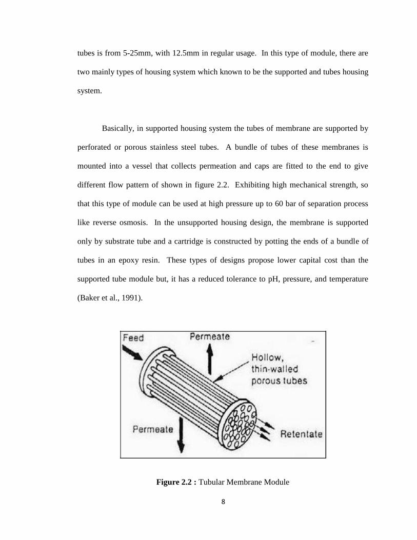
tubes is from 5-25mm, with 12.5mm in regular usage. In this type of module, there are
two mainly types of housing system which known to be the supported and tubes housing
system.
Basically, in supported housing system the tubes of membrane are supported by
perforated or porous stainless steel tubes. A bundle of tubes of these membranes is
mounted into a vessel that collects permeation and caps are fitted to the end to give
different flow pattern of shown in figure 2.2. Exhibiting high mechanical strength, so
that this type of module can be used at high pressure up to 60 bar of separation process
like reverse osmosis. In the unsupported housing design, the membrane is supported
only by substrate tube and a cartridge is constructed by potting the ends of a bundle of
tubes in an epoxy resin. These types of designs propose lower capital cost than the
supported tube module but, it has a reduced tolerance to pH, pressure, and temperature
(Baker et al., 1991).
Figure 2.2 : Tubular Membrane Module
9
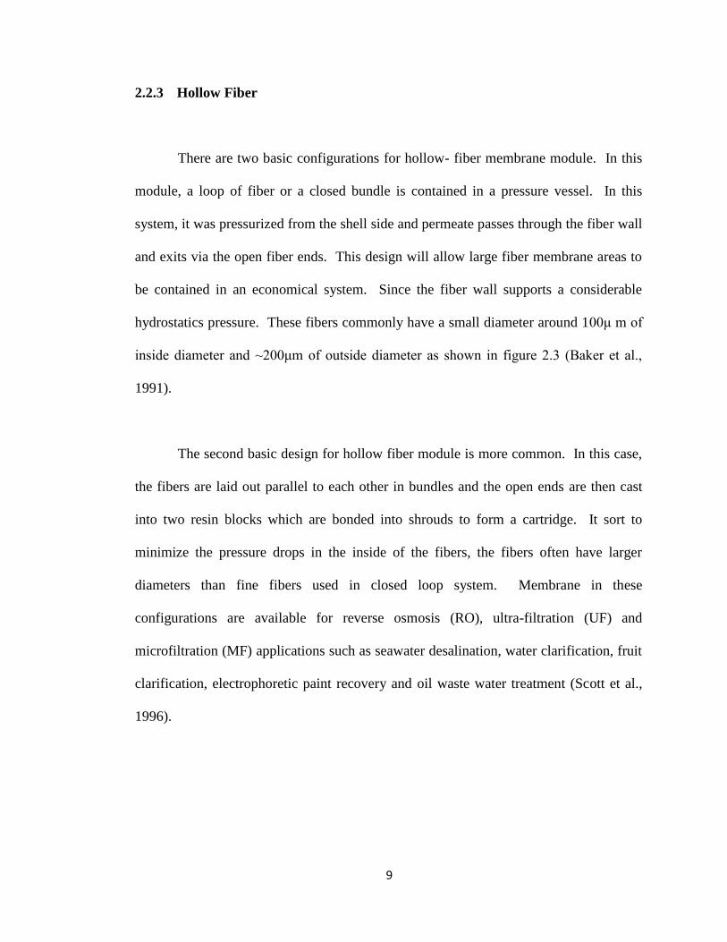
2.2.3 Hollow Fiber
There are two basic configurations for hollow- fiber membrane module. In this
module, a loop of fiber or a closed bundle is contained in a pressure vessel. In this
system, it was pressurized from the shell side and permeate passes through the fiber wall
and exits via the open fiber ends. This design will allow large fiber membrane areas to
be contained in an economical system. Since the fiber wall supports a considerable
hydrostatics pressure. These fibers commonly have a small diameter around 100μ m of
inside diameter and ~200μm of outside diameter as shown in figure 2.3 (Baker et al.,
1991).
The second basic design for hollow fiber module is more common. In this case,
the fibers are laid out parallel to each other in bundles and the open ends are then cast
into two resin blocks which are bonded into shrouds to form a cartridge. It sort to
minimize the pressure drops in the inside of the fibers, the fibers often have larger
diameters than fine fibers used in closed loop system. Membrane in these
configurations are available for reverse osmosis (RO), ultra-filtration (UF) and
microfiltration (MF) applications such as seawater desalination, water clarification, fruit
clarification, electrophoretic paint recovery and oil waste water treatment (Scott et al.,
1996).

10
Figure 2.3 : Hollow Fiber Membrane Module
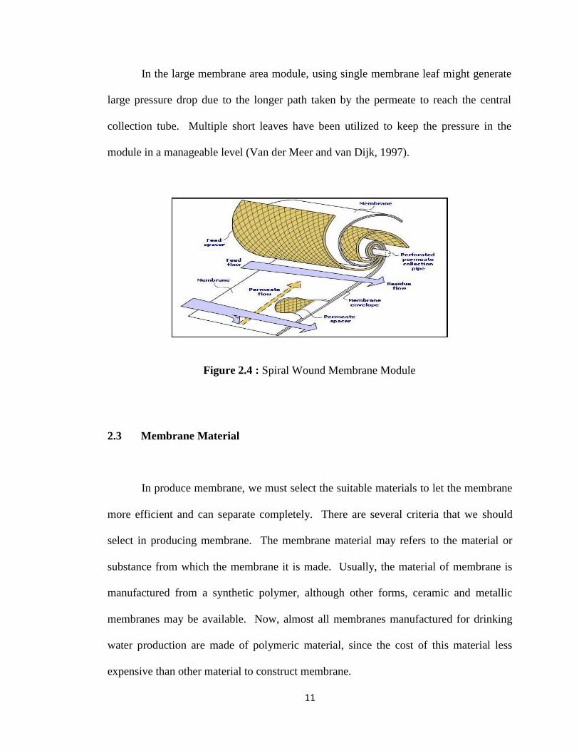
2.2.4 Spiral Wound
This type of module consist of membrane envelopes and feed spacers that wound
around a perforated central collection tube as shown in figure 2.4. Feed solution passes
through axially and down the module across the membrane envelope. A portion of the
feed solution permeates into the membrane envelope, where it spirals toward the center
and exits through the collection tube (Scott et al., 1996). These modules were designed
in an effort to pack as much membrane surface as possible into a given volume
(Senthilmurugan et al., 2005). Small scale spiral wound modules consist of a single
membrane leaf wrapped around the collection tube.
11
In the large membrane area module, using single membrane leaf might generate
large pressure drop due to the longer path taken by the permeate to reach the central
collection tube. Multiple short leaves have been utilized to keep the pressure in the
module in a manageable level (Van der Meer and van Dijk, 1997).
Figure 2.4 : Spiral Wound Membrane Module
2.3 Membrane Material
In produce membrane, we must select the suitable materials to let the membrane
more efficient and can separate completely. There are several criteria that we should
select in producing membrane. The membrane material may refers to the material or
substance from which the membrane it is made. Usually, the material of membrane is
manufactured from a synthetic polymer, although other forms, ceramic and metallic
membranes may be available. Now, almost all membranes manufactured for drinking
water production are made of polymeric material, since the cost of this material less
expensive than other material to construct membrane.