development of ieee complaint software ‘economical ... · pdf filedevelopment of ieee...
TRANSCRIPT
International Journal on Electrical Engineering and Informatics ‐ Volume 4, Number 2, July 2012
Development of IEEE Complaint Software ‘Economical Substation
Grounding System Designer’ Using MATLAB GUI Development Environment
Kaustubh A. Vyas and J. G. Jamnani
Department of Electrical Engineering
Institute of Technology, Nirma University Ahmedabad, Gujarat, India
[email protected], [email protected]
Abstract: Substations as a whole being an important part of the complete power system, grounding system of substations plays a vital role in overall performance of reliable power system. Grounding system of any substation deserves considerable care and attention at design stage, primarily to ensure electrical safety of persons working within or near substations. Looking to such great significance of grounding system design procedure, software which analyzes performance of ground grids of various shapes as per method described in IEEE standard 80 - 2000 has been developed using MATLAB®. Proposed software is able to calculate various performance parameters of grounding system for given input data related to grid geometry, soil and system conditions for all the basic shapes of grounding grid in uniform and two layered soils. Additionally this software can also suggest optimal i.e. most appropriate, safe and cost-effective design of the grounding system under given conditions and safety constraints. This software is deployed as windows standalone application using MATLAB run time compiler. Hence it can run on systems where MATLAB is not installed. In order to test the performance of the software, simple design problems have been solved and the results given by it are compared with those obtained form ETAP – GGS module and after verifying its technical performance it is found to be quite reliable tool in the field of grounding system design. Keywords:Ground grid; Optimal grounding system design; Safety criteria; Step voltage; Touch voltage; MATLAB
1. Introduction On its way from generating station to the end consumer, electrical power passes through different kinds of substations. Continuity of electrical power supply depends to a considerable extent upon the successful operation of substation. It is therefore essential to exercise at most care while designing and building a substation. Grounding system plays crucial role in the performance of a substation as it provides place for connecting system neutral points, equipment body and support structures to the earth. It also ensures safety of working personnel within the substation and enables earth fault detection and protection. It provides path for discharging the earth currents from neutrals of equipments, faults, surge arrestors, overhead shielding wires etc. It keeps step and touch potential within tolerable limits. Hence properly designed and installed grounding system ensures reliable performance of electrical substation, safety of persons working within or near substation and limits the ground potential rise GPR within acceptable levels. Substation grounding system being an essential part of the overall electrical system, its design is also of very much importance [1, 2]. Design of grounding system is an area in which there has been extensive study and analysis for last five decades. Several methods for grounding system analysis and design have been proposed. Numbers of computer programs have been developed to calculate safety parameters Received: March 31th, 2012. Accepted: August 8th, 2012
335
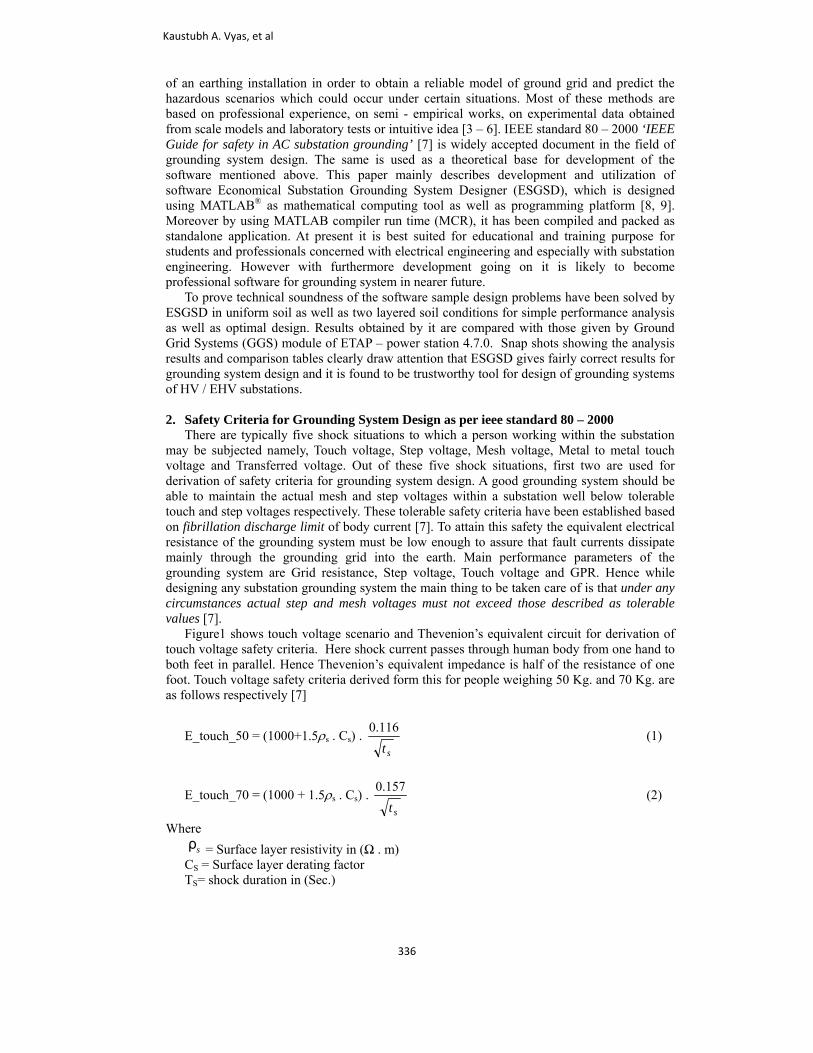
of an earthing installation in order to obtain a reliable model of ground grid and predict the hazardous scenarios which could occur under certain situations. Most of these methods are based on professional experience, on semi - empirical works, on experimental data obtained from scale models and laboratory tests or intuitive idea [3 – 6]. IEEE standard 80 – 2000 ‘IEEE Guide for safety in AC substation grounding’ [7] is widely accepted document in the field of grounding system design. The same is used as a theoretical base for development of the software mentioned above. This paper mainly describes development and utilization of software Economical Substation Grounding System Designer (ESGSD), which is designed using MATLAB® as mathematical computing tool as well as programming platform [8, 9]. Moreover by using MATLAB compiler run time (MCR), it has been compiled and packed as standalone application. At present it is best suited for educational and training purpose for students and professionals concerned with electrical engineering and especially with substation engineering. However with furthermore development going on it is likely to become professional software for grounding system in nearer future. To prove technical soundness of the software sample design problems have been solved by ESGSD in uniform soil as well as two layered soil conditions for simple performance analysis as well as optimal design. Results obtained by it are compared with those given by Ground Grid Systems (GGS) module of ETAP – power station 4.7.0. Snap shots showing the analysis results and comparison tables clearly draw attention that ESGSD gives fairly correct results for grounding system design and it is found to be trustworthy tool for design of grounding systems of HV / EHV substations. 2. Safety Criteria for Grounding System Design as per ieee standard 80 – 2000 There are typically five shock situations to which a person working within the substation may be subjected namely, Touch voltage, Step voltage, Mesh voltage, Metal to metal touch voltage and Transferred voltage. Out of these five shock situations, first two are used for derivation of safety criteria for grounding system design. A good grounding system should be able to maintain the actual mesh and step voltages within a substation well below tolerable touch and step voltages respectively. These tolerable safety criteria have been established based on fibrillation discharge limit of body current [7]. To attain this safety the equivalent electrical resistance of the grounding system must be low enough to assure that fault currents dissipate mainly through the grounding grid into the earth. Main performance parameters of the grounding system are Grid resistance, Step voltage, Touch voltage and GPR. Hence while designing any substation grounding system the main thing to be taken care of is that under any circumstances actual step and mesh voltages must not exceed those described as tolerable values [7]. Figure1 shows touch voltage scenario and Thevenion’s equivalent circuit for derivation of touch voltage safety criteria. Here shock current passes through human body from one hand to both feet in parallel. Hence Thevenion’s equivalent impedance is half of the resistance of one foot. Touch voltage safety criteria derived form this for people weighing 50 Kg. and 70 Kg. are as follows respectively [7]
E_touch_50 = (1000+1.5ρs . Cs) . st
116.0 (1)
E_touch_70 = (1000 + 1.5ρs . Cs) . st
157.0 (2)
Where
ρs = Surface layer resistivity in (Ω . m) CS = Surface layer derating factor TS= shock duration in (Sec.)
Kaustubh A. Vyas, et al
336
Figurestep voltaanother fimpedanc
Step volta
Figu
e 2. shows stepage safety critefoot, thus botce is twice of th
Fig
age safety crite
ure 1. Touch v
p voltage sceneria. Here shocth feet resistahe resistance of
gure 2. Step vo
eria for people
oltage scenario
nario and Thevck current pasances being if one foot.
oltage scenario
weighing 50 K
o and equivalen
venion’s equivases through huin series. Hen
o and equivalen
Kg. and 70 Kg.
nt circuit
alent circuit fouman body fronce Thevenion
nt circuit
are as follows
r derivation ofom one foot ton’s equivalent
s respectively.
f o t
Development of IEEE Complaint Software ‘Economical Substation
337
E_step_ 50 = (1000 + 6ρs . Cs) . st
116.0 (3)
E_step_70 = (1000 + 6ρs . Cs) . st
157.0 (4)
3. Development of Economical Substation Grounding system Designer IEEE Guide [7] demonstrates guide lines for design of grounding systems for HV / EHV AC substations, considering its performance at power frequencies only. Software Economical Substation Grounding System Designer (ESGSD) has been designed as per guide lines given in the same. Additionally this software provides option for modeling the soil as two layered one which is not given in IEEE guide. ESGSD has been developed using MATLAB – GUI as programming tool and MATLAB as mathematical computing tool [8, 9]. This has been designed using MATLAB version 7.6 R2008a; however it is deployed as standalone application hence it will work even in absence of MATLAB. Various salient features and detailed description of the software can be found from [10]. A. Methods of analysis This software analyzes performance of any grounding system in following two ways 1. Simple performance analysis of proposed grounding system by taking data related to grid
geometry, general system parameters and soil characteristics. 2. Optimal design of substation grounding system for all the five shapes of ground grid
namely, Square, Rectangular, Triangular, T shaped and L shaped in uniform as well as two layered soil.
In case of simple performance analysis, the software asks for data related to ground grid geometry, No. of ground rods, data regarding substation soil, generalized data related to power system for safety criteria establishment, conductor size and material etc. Then it calculates tolerable voltages as per safety criteria, actual mesh and step voltages, grounding system resistance (Rg), ground potential rise (GPR) and safety of the proposed grounding system. After calculation results are displayed in a separate window. In case of optimization, ESGSD suggests the most appropriate, safe and economical i.e. optimal design of grounding system. For the purpose of optimization, two dominating parameters affecting grounding system performance viz. No. of conductors in horizontal ground grid and No. of vertical ground rods, have been considered to be variable. Hence for obtaining optimal design of grounding system, No. of ground grid conductors are varied thereby altering separation between them for fixed grounding system area. Also No. of ground rods are varied to get most appropriate design at minimal cost. Depth of burial is again assumed constant and not varied for optimization. Information on effects of various parameters on grounding system performance can be found from [1, 2, 11 -14] B. Optimization problem formulation In order to get optimal design, following cost objective function has to be minimal subjected to safety criteria listed below it [15]. Optimization problem: Minimize the cost of grounding system given by
)()()()(),,,( yxyxccirrrirrrryx NLLNCCCNCLNLNNNf ⋅+⋅⋅⋅+⋅+⋅⋅=
(5)
Kaustubh A. Vyas, et al
338
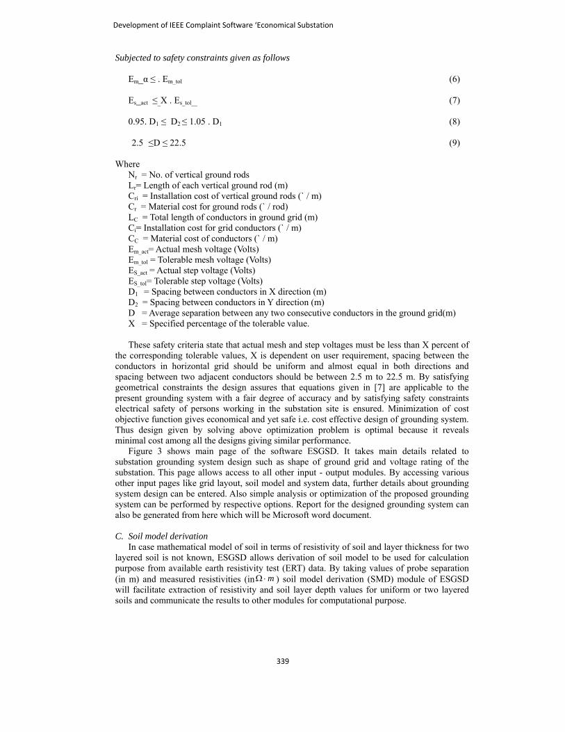
Subjected to safety constraints given as follows Em_α ≤ . Em_tol (6) Es_act ≤_X . Es_tol__ (7) 0.95. D1 ≤ D2 ≤ 1.05 . D1 (8)
2.5 ≤D ≤ 22.5 (9) Where
Nr = No. of vertical ground rods Lr= Length of each vertical ground rod (m) Cri = Installation cost of vertical ground rods (` / m) Cr = Material cost for ground rods (` / rod) LC = Total length of conductors in ground grid (m) Ci= Installation cost for grid conductors (` / m) CC = Material cost of conductors (` / m) Em_act= Actual mesh voltage (Volts) Em_tol = Tolerable mesh voltage (Volts) ES_act = Actual step voltage (Volts) ES_tol= Tolerable step voltage (Volts) D1 = Spacing between conductors in X direction (m) D2 = Spacing between conductors in Y direction (m) D = Average separation between any two consecutive conductors in the ground grid(m) X = Specified percentage of the tolerable value.
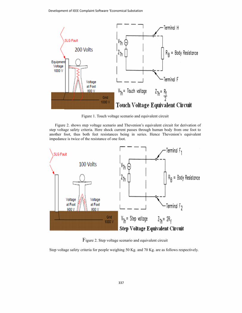
These safety criteria state that actual mesh and step voltages must be less than X percent of the corresponding tolerable values, X is dependent on user requirement, spacing between the conductors in horizontal grid should be uniform and almost equal in both directions and spacing between two adjacent conductors should be between 2.5 m to 22.5 m. By satisfying geometrical constraints the design assures that equations given in [7] are applicable to the present grounding system with a fair degree of accuracy and by satisfying safety constraints electrical safety of persons working in the substation site is ensured. Minimization of cost objective function gives economical and yet safe i.e. cost effective design of grounding system. Thus design given by solving above optimization problem is optimal because it reveals minimal cost among all the designs giving similar performance. Figure 3 shows main page of the software ESGSD. It takes main details related to substation grounding system design such as shape of ground grid and voltage rating of the substation. This page allows access to all other input - output modules. By accessing various other input pages like grid layout, soil model and system data, further details about grounding system design can be entered. Also simple analysis or optimization of the proposed grounding system can be performed by respective options. Report for the designed grounding system can also be generated from here which will be Microsoft word document. C. Soil model derivation In case mathematical model of soil in terms of resistivity of soil and layer thickness for two layered soil is not known, ESGSD allows derivation of soil model to be used for calculation purpose from available earth resistivity test (ERT) data. By taking values of probe separation (in m) and measured resistivities (in mΩ ⋅ ) soil model derivation (SMD) module of ESGSD will facilitate extraction of resistivity and soil layer depth values for uniform or two layered soils and communicate the results to other modules for computational purpose.
Development of IEEE Complaint Software ‘Economical Substation
339
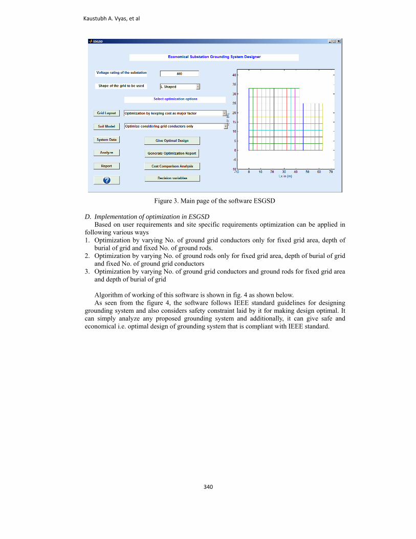
Figure 3. Main page of the software ESGSD
D. Implementation of optimization in ESGSD Based on user requirements and site specific requirements optimization can be applied in following various ways 1. Optimization by varying No. of ground grid conductors only for fixed grid area, depth of
burial of grid and fixed No. of ground rods. 2. Optimization by varying No. of ground rods only for fixed grid area, depth of burial of grid
and fixed No. of ground grid conductors 3. Optimization by varying No. of ground grid conductors and ground rods for fixed grid area
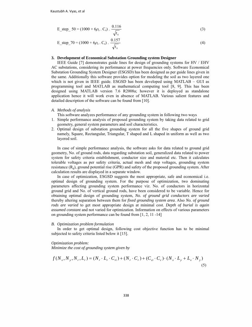
and depth of burial of grid Algorithm of working of this software is shown in fig. 4 as shown below. As seen from the figure 4, the software follows IEEE standard guidelines for designing grounding system and also considers safety constraint laid by it for making design optimal. It can simply analyze any proposed grounding system and additionally, it can give safe and economical i.e. optimal design of grounding system that is compliant with IEEE standard.
Kaustubh A. Vyas, et al
340
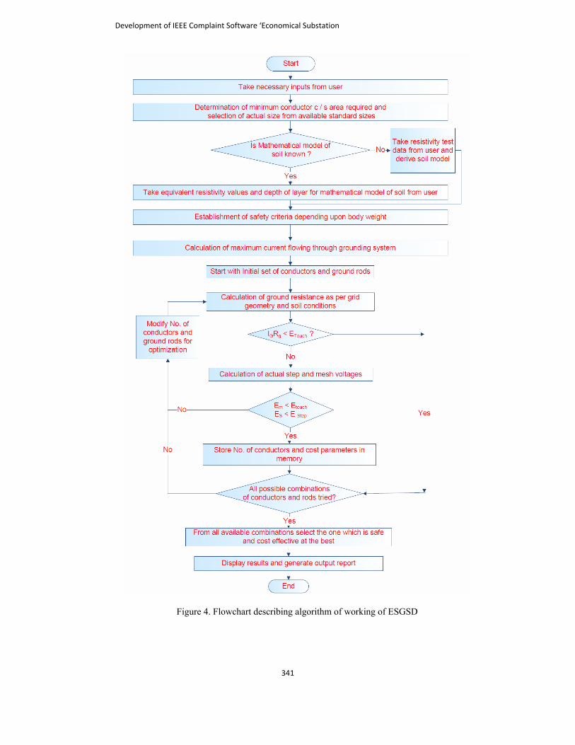
Figure 4. Flowchart describing algorithm of working of ESGSD
Development of IEEE Complaint Software ‘Economical Substation
341
4. Performance Evaluation of ESGSD A. Design of grounding system with ESGSD and verification of results with ETAP – GGS The software ESGSD has been developed using MATLAB and is based on IEEE – 80 – 2000 guidelines as described before. In order to validate the results given by the software following two problems have been solved by it and the same are also solved with the help of Ground Grid Systems (GGS) module of ETAP – professional software. ESGSD facilitates two types of analysis for grounding system design. 1. Simple performance analysis: Here it only gives output whether the system is safe or not
with the proposed grounding system as per data entered by user. 2. Optimization: It works in two ways as explained below.
If the proposed system is already safe then optimization gives the design at minimal cost i.e. monetary saving without sacrificing electrical safety performance.
If the initially proposed system is not safe then optimization makes design safe and that too at least cost.
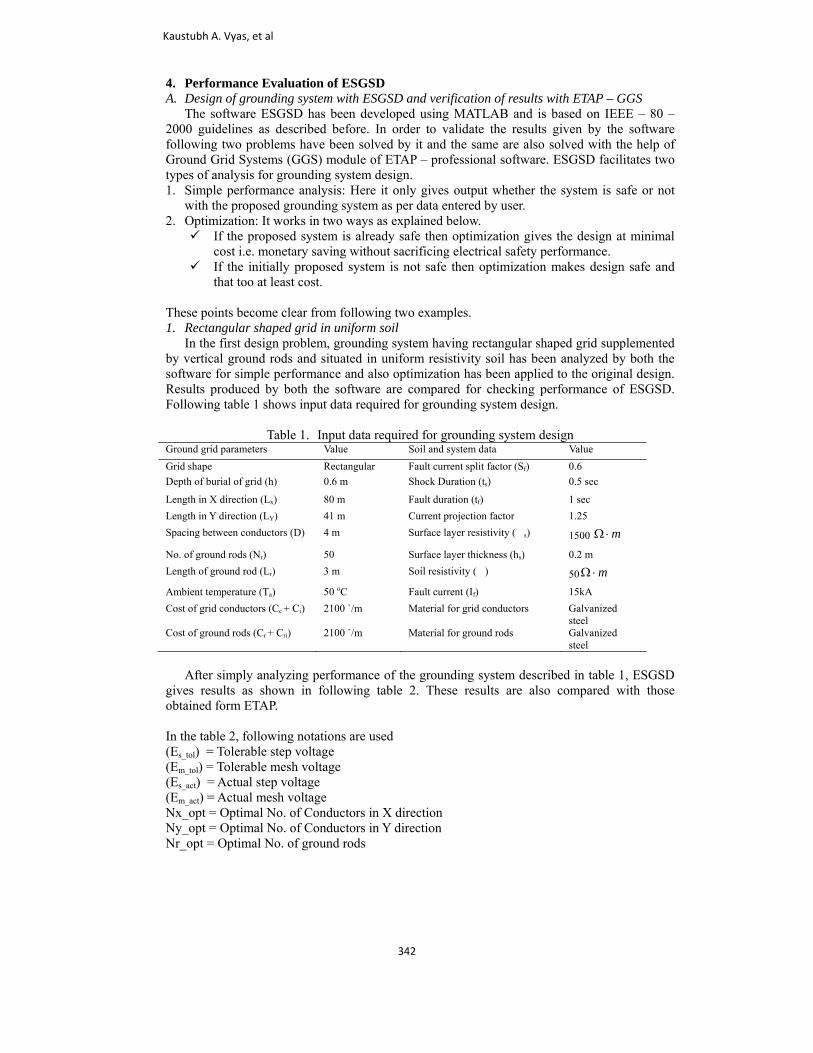
These points become clear from following two examples. 1. Rectangular shaped grid in uniform soil In the first design problem, grounding system having rectangular shaped grid supplemented by vertical ground rods and situated in uniform resistivity soil has been analyzed by both the software for simple performance and also optimization has been applied to the original design. Results produced by both the software are compared for checking performance of ESGSD. Following table 1 shows input data required for grounding system design.
Table 1. Input data required for grounding system design Ground grid parameters Value Soil and system data Value Grid shape Rectangular Fault current split factor (Sf) 0.6 Depth of burial of grid (h) 0.6 m Shock Duration (ts) 0.5 sec
Length in X direction (Lx) 80 m Fault duration (tf) 1 sec Length in Y direction (LY) 41 m Current projection factor 1.25 Spacing between conductors (D) 4 m Surface layer resistivity (s) 1500 mΩ ⋅
No. of ground rods (Nr) 50 Surface layer thickness (hs) 0.2 m Length of ground rod (Lr) 3 m Soil resistivity () 50 mΩ ⋅
Ambient temperature (Ta) 50 oC Fault current (If) 15kA Cost of grid conductors (Cc + Ci) 2100 `/m Material for grid conductors Galvanized
steel Cost of ground rods (Cr + Cri) 2100 `/m Material for ground rods Galvanized
steel After simply analyzing performance of the grounding system described in table 1, ESGSD gives results as shown in following table 2. These results are also compared with those obtained form ETAP. In the table 2, following notations are used (Es_tol) = Tolerable step voltage (Em_tol) = Tolerable mesh voltage (Es_act) = Actual step voltage (Em_act) = Actual mesh voltage Nx_opt = Optimal No. of Conductors in X direction Ny_opt = Optimal No. of Conductors in Y direction Nr_opt = Optimal No. of ground rods
Kaustubh A. Vyas, et al
342
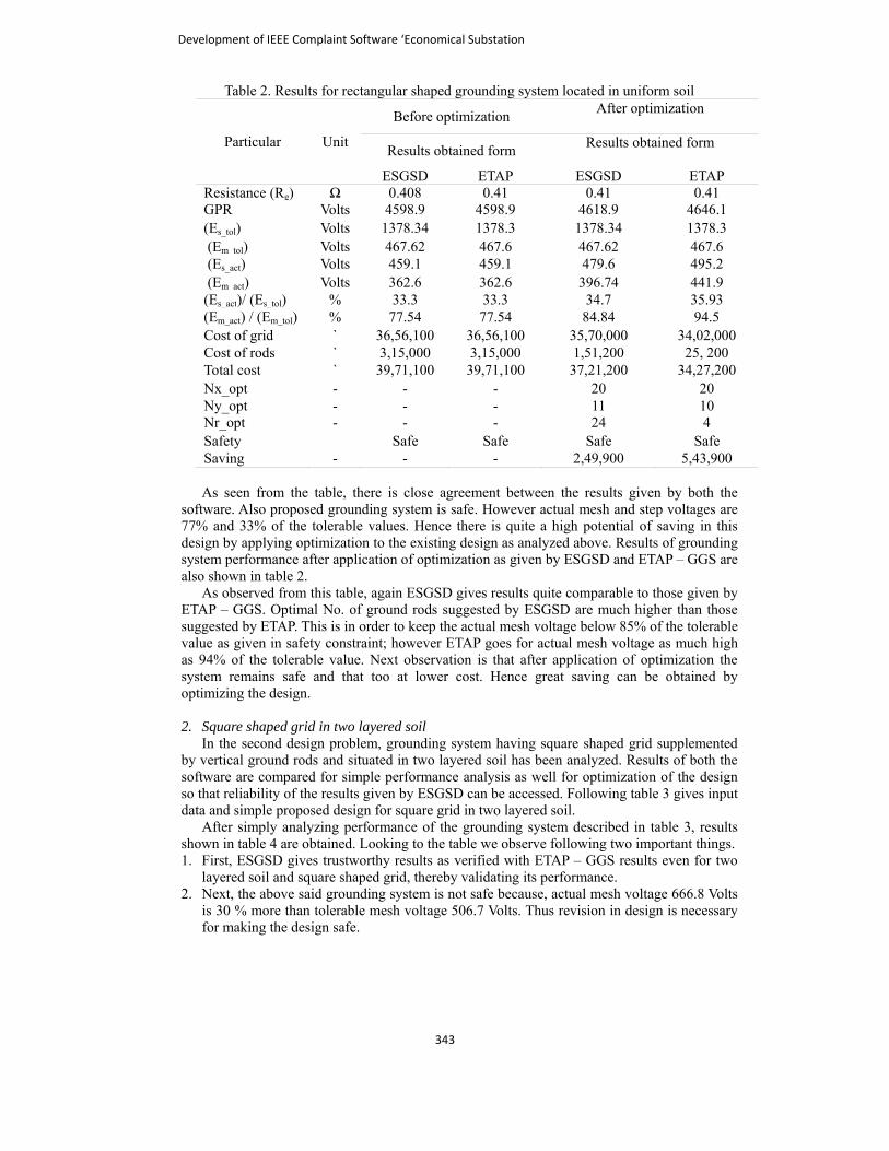
Table 2. Results for rectangular shaped grounding system located in uniform soil
Particular Unit
Before optimization After optimization
Results obtained form Results obtained form
ESGSD ETAP ESGSD ETAP Resistance (Rg) Ω 0.408 0.41 0.41 0.41 GPR Volts 4598.9 4598.9 4618.9 4646.1 (Es_tol) Volts 1378.34 1378.3 1378.34 1378.3 (Em_tol) Volts 467.62 467.6 467.62 467.6 (Es_act) Volts 459.1 459.1 479.6 495.2 (Em_act) Volts 362.6 362.6 396.74 441.9 (Es_act)/ (Es_tol) % 33.3 33.3 34.7 35.93 (Em_act) / (Em_tol) % 77.54 77.54 84.84 94.5 Cost of grid ` 36,56,100 36,56,100 35,70,000 34,02,000 Cost of rods ` 3,15,000 3,15,000 1,51,200 25, 200 Total cost ` 39,71,100 39,71,100 37,21,200 34,27,200 Nx_opt - - - 20 20 Ny_opt - - - 11 10 Nr_opt - - - 24 4 Safety Safe Safe Safe Safe Saving - - - 2,49,900 5,43,900
As seen from the table, there is close agreement between the results given by both the software. Also proposed grounding system is safe. However actual mesh and step voltages are 77% and 33% of the tolerable values. Hence there is quite a high potential of saving in this design by applying optimization to the existing design as analyzed above. Results of grounding system performance after application of optimization as given by ESGSD and ETAP – GGS are also shown in table 2. As observed from this table, again ESGSD gives results quite comparable to those given by ETAP – GGS. Optimal No. of ground rods suggested by ESGSD are much higher than those suggested by ETAP. This is in order to keep the actual mesh voltage below 85% of the tolerable value as given in safety constraint; however ETAP goes for actual mesh voltage as much high as 94% of the tolerable value. Next observation is that after application of optimization the system remains safe and that too at lower cost. Hence great saving can be obtained by optimizing the design. 2. Square shaped grid in two layered soil In the second design problem, grounding system having square shaped grid supplemented by vertical ground rods and situated in two layered soil has been analyzed. Results of both the software are compared for simple performance analysis as well for optimization of the design so that reliability of the results given by ESGSD can be accessed. Following table 3 gives input data and simple proposed design for square grid in two layered soil. After simply analyzing performance of the grounding system described in table 3, results shown in table 4 are obtained. Looking to the table we observe following two important things. 1. First, ESGSD gives trustworthy results as verified with ETAP – GGS results even for two
layered soil and square shaped grid, thereby validating its performance. 2. Next, the above said grounding system is not safe because, actual mesh voltage 666.8 Volts
is 30 % more than tolerable mesh voltage 506.7 Volts. Thus revision in design is necessary for making the design safe.
Development of IEEE Complaint Software ‘Economical Substation
343
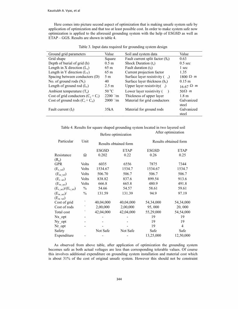
Here comes into picture second aspect of optimization that is making unsafe system safe by application of optimization and that too at least possible cost. In order to make system safe now optimization is applied to the aforesaid grounding system with the help of ESGSD as well as ETAP – GGS. Results are shown in table 4.
Table 3. Input data required for grounding system design
Table 4. Results for square shaped grounding system located in two layered soil
Particular Unit
Before optimization After optimization
Results obtained form Results obtained form
ESGSD ETAP ESGSD ETAP Resistance (Rg)
Ω 0.202 0.22 0.26 0.25
GPR Volts 6035 6556 7875 7344 (Es_tol) Volts 1534.67 1534.7 1534.67 1534.7 (Em_tol) Volts 506.70 506.7 506.7 506.7 (Es_act) Volts 838.82 837.6 899.54 913.6 (Em_act) Volts 666.8 665.8 480.9 491.8 (Es_act)/(Es_tol) % 54.66 54.57 58.61 59.61 (Em_act)/ (Em tol)
% 131.59 131.39 94.9 97.19
Cost of grid ` 40,04,000 40,04,000 54,34,000 54,34,000 Cost of rods ` 2,00,000 2,00,000 95, 000 20, 000 Total cost ` 42,04,000 42,04,000 55,29,000 54,54,000 Nx_opt - - - 19 19 Ny_opt - - - 19 19 Nr_opt - - - 19 4 Safety Not Safe Not Safe Safe Safe Expenditure - - - 13,25,000 12,50,000
As observed from above table, after application of optimization the grounding system becomes safe as both actual voltages are less than corresponding tolerable values. Of course this involves additional expenditure on grounding system installation and material cost which is about 31% of the cost of original unsafe system. However this should not be constraint
Ground grid parameters Value Soil and system data Value Grid shape Square Fault current split factor (Sf) 0.63 Depth of burial of grid (h) 0.5 m Shock Duration (ts) 0.5 sec Length in X direction (Lx) 65 m Fault duration (tf) 1 sec Length in Y direction (LY) 65 m Current projection factor 1.35 Spacing between conductors (D) 5 m Surface layer resistivity (s) 1800 mΩ ⋅ No. of ground rods (Nr) 40 Surface layer thickness (hs) 0.15 m Length of ground rod (Lr) 2.5 m Upper layer resistivity() 16.67 mΩ ⋅ Ambient temperature (Ta) 50 oC Lower layer resistivity () 50 mΩ ⋅ Cost of grid conductors (Cc + Ci) 2200 `/m Thickness of upper layer 1.8 m Cost of ground rods (Cr + Cri) 2000 `/m Material for grid conductors Galvanized
steel Fault current (If) 35kA Material for ground rods Galvanized
steel
Kaustubh A. Vyas, et al
344
because in order bring actual voltages below the specified maximum voltages, levels more no. of conductors are supposed to be used and after all personnel safety is of major interest than money. Also the design suggested by ESGSD is optimal and the most favorable at least at preliminary analysis stage. This is also verified by corresponding results of ETAP. 3. General observations and discussion We can summarize complete description given up till now as follows
Newly developed software ESGSD performs quite reliably while evaluating technical performance of any grounding system in uniform as well as two layer modeled soil for all the five grid shapes mentioned above which can also be verified form[16].
Also it gives most favorable design for grounding system of any HV / EHV AC substations considering the safety criteria established by IEEE, furthermore it keeps design optimal i.e. safe and cost – effective .
Optimization does not mean that the design obtained after optimization is only cheap or only safe, rather it considers both factors i.e. technical performance in terms of electrical safety and cost. Optimization gives safe and economical design. Neither the technical performance is underestimated nor is the system made over designed and excessively costly.
Results obtained by ESGSD are validated by professional software ETAP – GGS for all the cases. It proves technical soundness of the novel software thus confirming it as a reliable tool in substation grounding system design as far as preliminary grounding system performance at power frequency is concerned.
5. Conclusion In this paper initially importance of grounding system is starched at and newly developed software is briefly introduced. Next, safety criterion is explained along with appropriate figures and equations. Then information about development of software together with its salient features is given. Next objective function for optimizing the grounding system design along with the safety and geometrical design constraints is described. Then general design methodology as per IEEE guidelines is discussed with flowchart of program algorithm. Finally performance of newly developed software ESGSD is evaluated by solving two design problems and comparing results with those given by professional software ETAP. Analysis results clearly show technical soundness of the novel software and importance of application of optimization. Finally ESGSD can be considered as an effective design tool at least at preliminary level for designing grounding system of AC substations considering only power frequency performance parameters. It can serve quite useful to design engineers for designing preliminary grounding system as per standards rather than using empirical hand calculation methods based on rough approximation or previous experiences. References [1]. Kaustubh A. Vyas and J.G. Jamnani, “Optimal design and development of software for
design of substation grounding system”, 2nd International Conference on Current Trends in Technology – NUiCONE, Ahmedabad, Gujarat, India, December 2011, pp. 1 – 6.
[2]. Project report available at: https://docs.google.com/viewer?a=v&pid=sites&srcid=ZGVmYXVsdGRvbWFpbnxncm91bmRpbmdzeXN0ZW1kZXNpZ258Z3g6NDY2NWM2NTVlYzljNjk0ZQ
[3]. F. P. Dawalibi and D. Mukhedkar, “Optimum Design of Substation Grounding in a two Layer Earth Structure, Part - 1”, IEEE Trans. on PAS, Vol. PAS 94, No. 2, pp. 252-272, 1974.
[4]. J. G. Sverak, “Optimized Grounding Grid Design Using Variable Spacing Technique”, IEEE Trans. on PAS, Vol. PAS 95, No. 1, pp. 362-374, 1976.
[5]. J. Nahman, and D. Salamon, “Earthing system modeling by element aggregation” IEE PROCEEDINGS, Vol. 133, Part. C, No. I, pp. 54 – 58, January 1986.
Development of IEEE Complaint Software ‘Economical Substation
345
[6]. J. ATran
[7]. IEEE[8]. Dr. A
Std. Scie
[9]. http[10]. Help
https91bm
[11]. John[12]. A. P
effec2007
[13]. AhdcalcuNov
[14]. Gup[15]. Gary
2011[16]. Proj
https91bm
education
power sythan 22 pprojects f
A. Sulivan, “Ansm. Distrib., VE guide for safAttia A. El-Fer80 - 2000 us
ence and Techn://www.mathwp file s://docs.googlemRpbmdzeXNn D Mc DonaldPuttarach, N.Chct of GPR”, IE7, pp.1 – 5.
dab Elmorshedulation for gr
vember 2006, ppta B. R, Powery Gilbert, “Hi1 ect s://docs.googlemRpbmdzeXN
KaustHe isEnginHe obM.TecUnivePowerGroun
nal purpose. He
J. G. 1971. EngineGujarafrom tElectriyears levels
ystems, High vapers in Nation
for Industry. H
Alternative eartVol. 145, pp. 27fety in AC subsrgany, “Designsing GUI and nology, Vol. 3 Nworks.in/help/te
of e.com/viewer?a
N0ZW1kZXNpd, Electrical pohakpitak, T. KaEEE PES Conf
dy Rabah Amrounding gridspp. 501 – 505.r System Analyigh voltage gr
repoe.com/viewer?a
N0ZW1kZXNp
tubh A. Vyass currently A
neering at Kalobtained his B.Ech (Electrical ersity, Ahmedar System Protnding Systeme has published
Jamnani wasHe is currentl
eering at Gujarat, India. He othe Indian Insical Engineerinof teaching e and 2 years
voltage Enginnal/Internation
He is a life mem
thing calculati71- 280, May 1station groundin and optimizeMATLAB cod
No. 7, pp. 6033echdoc/creating
softwara=v&pid=sites
pZ258Z3g6Mjgower substationasirawat and Cference and Exp
er Sherif Ghos”, First Inter
ysis and Designrounding syste
ort a=v&pid=sites
pZ258Z3g6OTQ
was born in MAssistant Profol Institute and. (Electrical) inPower System
abad, Gujarat, Itection, Power
m Design andd 4 papers in N
s born in Godly Professor arat Power Engobtained his Bstitute of Techng from M. S.experience at bs Industrial expeering and El
nal conferencesmber of ISTE a
ons for grids 1998. ing, IEEE stane substation grdes”, Internati3- 6039, July 2g_guis/bqz6p8re ava
s&srcid=ZGVmg5ODkzYTE0Zn engineering, C. Pongsriwat, xposition, Joha
oneim, Holgerrnational Pow
n: S. Chand & ms”, PhD the
avails&srcid=ZGVmQ5MWEyNmE
Mandvi, Gujarafessor in the d Research Insn 2009 from L.ms) from InstiIndia in 2012. r System Stabd developmen
National/Interna
dhra-city, Gujaand Head in thgineering and RB.E. Electrical hnology, Roor. University, Vboth the undeperience. His lectrical mach
s/Journals and cand member of
and rods”, Pr
dard 80, 2000 ounding grid bonal Journal o
2011 1.html ailable mYXVsdGRvbZGVhNmE0OCRC Press: 20“Ground layer
annesburg, Sou
r Hirsch, “Surwer and Energ
Company Limesis, University
lable mYXVsdGRvbE4NzA0NmYz
at, India on MDepartment
stitute, Kalol, . D. Engineerinitute of TechnHis areas of in
bility, Electricant of softwarational confere
arat, India on he DepartmenResearch Institin 1993, M.T
rkee, in 2002 Vadodara. He ergraduate and areas of in
hines. He has pcompleted manIEEE.
roc. IEE Gen.
based on IEEEof Engineering
at :bWFpbnxncmQ
006 r depth and theuth Africa, July
rface potentialgy Conference,
mited, 2008 y of Waterloo,
at:bWFpbnxncmz.
March 25, 1988of Electrical
Gujarat, Indiang College andnology, Nirmanterest includeal Switchgear,re useful fornces/Journals.
December 20,nt of Electricaltute, Mehsana,
Tech. Electricaland Ph.D. inhas over 17
d postgraduateterest include
published moreny consultancy
.
E g
:
e y
l ,
,
:
. l .
d a e , r
, l , l n 7 e e e y
Kaustubh A. Vyas, et al
346