development of guidelines for usage of - dot7.state.pa.us · development of guidelines for usage of...
TRANSCRIPT

Development of Guidelines for Usage of High Percent RAP in Warm-Mix Asphalt Pavements FINAL REPORT December 15, 2011 By Mansour Solaimanian, Scott Milander, Ilker Boz and Shelley M. Stoffels The Thomas D. Larson Pennsylvania Transportation Institute COMMONWEALTH OF PENNSYLVANIA DEPARTMENT OF TRANSPORTATION CONTRACT No. 510602 PROJECT No. PSU 032

This work was sponsored by the Pennsylvania Department of Transportation, the Mid-Atlantic Universities Transportation Center, and the U.S. Department of Transportation, Federal Highway Administration. The contents of this report reflect the views of the authors, who are responsible for the facts and the accuracy of the data presented herein. The contents do not necessarily reflect the official views or policies of the Federal Highway Administration, U.S. Department of Transportation, the Mid-Atlantic Universities Transportation Center, or the Commonwealth of Pennsylvania at the time of publication. This report does not constitute a standard, specification, or regulation.

Technical Report Documentation Page
1. Report No. FHWA-PA-2011-013-PSU 032
2. Government Accession No. 3. Recipient’s Catalog No.
4. Title and Subtitle Development of Guidelines for Usage of High Percent RAP in Warm-Mix Asphalt Pavements
5. Report Date December 15, 2011
6. Performing Organization Code
7. Author(s) Mansour Solaimanian, Scott Milander, Ilker Boz, Shelley Stoffels
8. Performing Organization Report No. LTI 2012-02
9. Performing Organization Name and Address The Thomas D. Larson Pennsylvania Transportation Institute The Pennsylvania State University 201 Transportation Research Building University Park, PA 16802-4710
10. Work Unit No. (TRAIS)
11. Contract or Grant No. 510602, PSU 032
12. Sponsoring Agency Name and Address The Pennsylvania Department of Transportation Bureau of Planning and Research Commonwealth Keystone Building 400 North Street, 6th Floor Harrisburg, PA 17120-0064
13. Type of Report and Period Covered Final Report 11/01/2010 – 11/25/2011
14. Sponsoring Agency Code
15. Supplementary Notes COTR: Sean Oldfield, 717-783-2444
16. Abstract
Road construction using warm-mix asphalt has been rapidly gaining popularity in the United States, in part because WMA is believed to be friendlier to the environment as compared to hot-mix asphalt. Parallel to this rapid growth in WMA construction is utilization of reclaimed asphalt pavement (RAP) in road construction. Research was conducted to develop guidelines for using high percentages of RAP in WMA. The laboratory work was focused on three WMA technologies: water foaming, a chemical additive (Evotherm™), and an organic additive (Sasobit™). The work included RAP characterization, mix design, moisture damage evaluation, and rutting evaluation using the Superpave Shear Tester and Model Mobile Load Simulator Third Scale. Accelerated load testing was conducted at a temperature range of approximately 42 to 50°C for 400,000 cycles of loading. Rutting resistance of the mixes was rated as fair to good. This research indicates that it is possible to produce WMA with high RAP having sufficient moisture damage and rutting resistance. However, a mix design established for HMA does not necessarily produce satisfactory performance when used with WMA, and it is important that moisture damage and rutting susceptibility of WMA be evaluated for any mix design, even though that mix design may have demonstrated satisfactory performance for HMA.
17. Key Words
Warm-mix asphalt, rutting, moisture damage, accelerated loading, foaming, Evotherm, Sasobit
18. Distribution Statement No restrictions. This document is available from the National Technical Information Service, Springfield, VA 22161
19. Security Classif. (of this report) Unclassified
20. Security Classif. (of this page) Unclassified
21. No. of Pages 126
22. Price
Form DOT F 1700.7 (8-72) Reproduction of completed page authorized


v
TABLE OF CONTENTS LIST OF FIGURES .......................................................................................................... vii LIST OF TABLES ............................................................................................................. ix ACKNOWLEDGEMENTS ................................................................................................ x EXECUTIVE SUMMARY .............................................................................................. 1 CHAPTER ONE: INTRODUCTION ............................................................................. 4
Background ..................................................................................................................... 4 Work Plan ....................................................................................................................... 5
Task 1: Survey of Agencies on WMA/RAP Design and Construction ..................... 6 Task 2: Review Basic and Applied Research on WMA Pavements with RAP ......... 6 Task 3: Develop Experimental Plan for Laboratory Investigation ............................ 6 Task 4: Submit Interim Report .................................................................................. 6 Task 5: Procurement of Materials .............................................................................. 6 Task 6: Conduct Experimental Plan Developed in Phase I ....................................... 7 Task 7: Develop Draft Guidelines for Usage of High RAP with WMA Technology ................................................................................................. 7
CHAPTER TWO: SURVEY OF STATES AND LITERATURE REVIEW .............. 8
Survey of Agencies on WMA/RAP Design and Construction ....................................... 8 Review Basic and Applied Research on WMA Pavements with RAP ......................... 10
CHAPTER THREE: EXPERIMENTAL PROGRAM .............................................. 13
Experimental Plan ......................................................................................................... 13 WMA Technologies .................................................................................................. 13 Materials ................................................................................................................... 13 Additive Application Rates and Temperatures ......................................................... 14 Mix Type and RAP Content ..................................................................................... 14 Blending Procedure ................................................................................................... 15 Equipment and Tests ................................................................................................. 17
RAP Characterization ................................................................................................... 18 RAP Extraction ......................................................................................................... 18 RAP Binder Recovery............................................................................................... 18 RAP Aggregate Gradation and Binder Content Using Ignition Oven ...................... 19 RAP Binder Aging Using the Rolling Thin Film Oven ............................................ 19 RAP Binder Stiffness Using Dynamic Shear Rheometer ......................................... 20 RAP Binder Stiffness Using Bending Beam Rheometer .......................................... 21
Evaluation of Moisture Susceptibility (Resistance to Moisture Damage) .................... 26 Specimen Preparation: .............................................................................................. 27 Specimen Conditioning:............................................................................................ 27
Testing with the Model Mobile Load Simulator 1/3 Scale ........................................... 29 MMLS3 Sample Preparation .................................................................................... 31

vi
MMLS3 Sample Testing ........................................................................................... 31 Superpave Shear Tester................................................................................................. 32
SST Specimen Preparation ....................................................................................... 33 SST Testing Procedure ............................................................................................. 35
CHAPTER FOUR: ANALYSIS, INTERPRETATION, AND FINDINGS ............. 36
Characterization of Materials ........................................................................................ 36 RAP ........................................................................................................................... 36 Virgin Aggregate ...................................................................................................... 39
Determination of RAP Binder Grade ............................................................................ 39 Results from Dynamic Shear Rheometer Testing ..................................................... 39 Results from the Bending Beam Rheometer Test ..................................................... 40
Investigation of Gradation, Air Void, and Binder Blending ......................................... 44 HMA-RAP Study 1 ................................................................................................... 44 HMA-RAP Study 2 ................................................................................................... 45 HMA-RAP Study 3 ................................................................................................... 47 HMA-RAP Study 4 ................................................................................................... 48 HMA-RAP Study 5 ................................................................................................... 49 HMA-RAP Study 6 ................................................................................................... 50 HMA-RAP Study Summary ..................................................................................... 50
Determination of Optimum Binder Content ................................................................. 51 Results from Moisture Susceptibility Evaluation ......................................................... 55 Results from Testing with MMLS3 .............................................................................. 57 Results from Constant Height Repeated Shear Test ..................................................... 63
CHAPTER FIVE: CONCLUSIONS AND RECOMMENDATIONS ...................... 67
Summary and Conclusions ........................................................................................... 67 Recommendations ......................................................................................................... 68
REFERENCES ................................................................................................................ 70 APPENDIX A: RESULTS OF MIX DESIGN APPENDIX B: RESULTS FROM MOISTURE DAMAGE TESTING - AASHTO T283
APPENDIX C: RESULTS OF ACCELERATED PAVEMENT TESTING FROM MMLS3 APPENDIX D: RESULTS FROM REPEATED SHEAR AT CONSTANT HEIGHT - AASHTO T320 APPENDIX E: DRAFT GUIDELINES FOR USAGE OF WARM-MIX ASPHALT WITH HIGH PERCENT RAP (HIGH-RAP WMA)

vii
LIST OF FIGURES Figure 1. Flow Chart of Tasks ........................................................................................... 5 Figure 2. (a) Rolling Thin Film Oven (RTFO), (b) Binder Bottles at Different Stages .. 19 Figure 3. Dynamic Shear Rheometer (DSR) ................................................................... 21 Figure 4. Loading Configuration in DSR ........................................................................ 21 Figure 5. Bending Beam Rheometer ................................................................................ 22 Figure 6. Loading Configuration and Response in Bending Beam Rheometer ............... 22 Figure 7. Gradation Plot for Zero Percent RAP Mixes .................................................... 24 Figure 8. Gradation Plot for 15 Percent RAP Mixes ....................................................... 24 Figure 9. Gradation Plot for 35 Percent RAP Mixes ....................................................... 25 Figure 10. SGC Specimen Set in the Loading Frame for Indirect Tensile Testing and Corresponding Loading in Diametral Direction ...................................... 28 Figure 11. Trimmed SGC Specimens Arranged for MMLS3 Tracking .......................... 30 Figure 12. MMLS3 Loading System Assembled and Ready to Load Specimens ........... 30 Figure 13. Dimensions of Trimmed Specimens .............................................................. 31 Figure 14. Profilometer Used to Measure Rut Profiles.................................................... 32 Figure 15. Tracked Specimens after 400,000 Cycles of MMLS3 Loading. .................... 32 Figure 16. Sawed Face of 6-inch SGC Specimen for SST .............................................. 33 Figure 17. Gluing Jig for Fixing Platens to the Shear Test Specimen ............................. 34 Figure 18. Assembly of Specimen and LVDTs for Deformation Measurement ............. 34 Figure 19. LVDT Assembly for Measuring Shear Deformation ..................................... 35 Figure 20. RAP Binder Content from Extractions ........................................................... 36 Figure 21. RAP Binder Content from Burn-Offs............................................................. 37 Figure 22. RAP Gradation Plot ........................................................................................ 38 Figure 23. Determination of RAP Binder Critical High Temperature under No Lab Aging Condition ............................................................................................. 40 Figure 24. Determination of RAP Binder Critical High Temperature under Lab RTFO Aged Condition ......................................................................................... 41 Figure 25. Determination of RAP Binder Critical Intermediate Temperature ................ 41 Figure 26. Determination of RAP Binder Critical Low Temperature Based on Stiffness................................................................................................................... 42 Figure 27. Determination of RAP Binder Critical Low Temperature Based on Relaxation Index, m ..................................................................................... 42 Figure 28. Determination of Performance Grade of RAP-Virgin Binder Blend ............. 43 Figure 29 Air Voids for HMA with no RAP at Design Number of Gyrations ................. 52 Figure 30. Air Voids for Different Mixes at Design Number of Gyrations .................... 53 Figure 31. Indirect Tensile Strength of Different Mixes at Design Number of Gyrations ................................................................................................................. 54 Figure 32. Tensile Strength Ratios for Different Mixes .................................................. 56 Figure 33. Temperature Variation with Time during MMLS3 Testing ........................... 58 Figure 34. Maximum Rutting after 400,000 Cycles of MMLS3 Loading ....................... 59 Figure 35. Rutting Profiles for All Mixes after 400,000 Cycles of MMLS3 Loading .... 59 Figure 36. Rutting Profiles for 15 Percent RAP Mixes after 400,000 Cycles of MMLS3 Loading ......................................................................................................... 60

viii
Figure 37. Rutting Profiles for 35 Percent RAP Mixes after 400,000 Cycles of MMLS3 Loading ......................................................................................................... 60 Figure 38. Maximum Rutting after 100,000 Cycles of MMLS3 Loading ....................... 61 Figure 39. Rutting Profiles for All Mixes after 100,000 Cycles of MMLS3 Loading .... 62 Figure 40. Rutting Profiles for 15 Percent RAP Mixes after 100,000 Cycles of MMLS3 Loading ......................................................................................................... 62 Figure 41. Rutting Profiles for 35 Percent RAP Mixes after 100,000 Cycles of MMLS3 Loading ......................................................................................................... 63 Figure 42. Permanent Shear Strain for Different Mixes from SST ................................. 63

ix
LIST OF TABLES Table 1. Materials Used in This Research Project ........................................................... 14 Table 2. Additive Application Rates and Mixing and Compaction Temperatures Used in This Study ....................................................................................................... 15 Table 3. Testing Matrix to Evaluate the Effect of RAP Content on WMA Properties .... 17 Table 4. Mix Gradations for 0% RAP, 15% RAP and 35% RAP ................................... 23 Table 5. Testing Matrix for Mix Design .......................................................................... 26 Table 6. Testing Matrix for Moisture Damage Test ........................................................ 26 Table 7. Test Results from PTM 757 Method A and PTM 702 ...................................... 37 Table 8. RAP Gradation: RAP 1—Black Rock, RAP 2—Extraction, RAP 3— Ignition ......................................................................................................... 38 Table 9. RAP Aggregate Specific Gravities .................................................................... 39 Table 10 Virgin Aggregate Gravities ............................................................................... 39 Table 11. Mix Gradation for HMA-RAP Study 1 ........................................................... 45 Table 12. Test Results for HMA-RAP Study 1 ............................................................... 45 Table 13. Mix Gradation for HMA-RAP Study 2 ........................................................... 46 Table 14. Test Results for HMA-RAP Study 2 ............................................................... 47 Table 15. Mix Gradation for HMA-RAP Study 3 ........................................................... 47 Table 16. Test Results for HMA-RAP Study 3 ............................................................... 48 Table 17. Proportion and Gradation of the Mixtures ....................................................... 48 Table 18. Testing Results ................................................................................................. 48 Table 19. Mix Gradation for HMA-RAP Study 5 and 6 .................................................. 49 Table 20. Test Results for HMA-RAP Study 5 ............................................................... 49 Table 21. Test Results for HMA-RAP Study 6 ............................................................... 50 Table 22. HMA-RAP Study Summary ............................................................................ 51 Table 23. Air Voids and Indirect Tensile Strength for Different Mixes at Design Number of Gyrations ................................................................................................... 55 Table 24. Summary of Results from Moisture Damage Study ........................................ 57 Table 25. Permanent Shear Strain from SST after 5,000 Cycles ..................................... 64 Table 26. Criteria to Determine Mix Rutting Resistance ................................................ 65 Table 27. Predicted Rut Depths Based on Shear Test Results for a 75-mm Asphalt Layer ............................................................................................................... 66

x
ACKNOWLEDGEMENTS The work upon which this report is based is the result of almost eleven months of laboratory investigation. Financial support for this project was provided by the Pennsylvania Department of Transportation (PennDOT). This support is greatly appreciated. Ms. Lisa Tarson and Mr. Sean Oldfield of the PennDOT Bureau of Research and Planning served as the project manager and contract administrator, respectively. Their guidance is truly appreciated. Ms. Sheri Little of the PennDOT Bureau of Construction and Materials served as technical liaison with PennDOT. Her counsel and direction were of great value to this project. Also recognized is the invaluable help and guidance provided by the project technical panel. The authors are also grateful to Mr. Michael Casper, who provided support with editing and formatting the report.
1
EXECUTIVE SUMMARY
Road construction using warm-mix asphalt (WMA) has been rapidly gaining popularity in the United States. The number of WMA projects constructed has grown aggressively and steadily. A major reason for such rapid success is that WMA is friendlier to the environment as compared to hot-mix asphalt (HMA), and is in concord with green highway initiatives. This technology is believed to reduce construction energy consumption and emissions without sacrificing the quality of the constructed pavement, as lower temperatures are used to produce and construct WMA. Parallel to this rapid growth in WMA construction is the attention placed on usage of reclaimed asphalt pavement (RAP) in asphalt construction. RAP has been used in HMA construction for many years, but its application in WMA is relatively new. It is probably true that 35 percent RAP is the highest amount included in the mix designs submitted by producers for review and approval by Pennsylvania Department of Transportation (PennDOT). Currently, the performance of this level of RAP in WMA is not well established. Therefore, PennDOT sponsored this research project to evaluate the performance of high-RAP WMA for wearing courses and to develop guidelines for such usage. The research consisted of a literature review, telephone/e-mail interviews of key states, and laboratory testing of high-RAP WMA. The survey states consisted of California, Florida, Indiana, New York, Ohio, Texas, and Virginia. Department of Transportation personnel from these states were contacted to discuss their usage of RAP-WMA. The focus was on agencies that currently allow higher percentages of RAP in HMA or that have been leaders in implementing WMA. While the agency policies and approaches vary significantly, all are currently either in the process of assessing their warm-mix implementation or have adopted permissive specifications for WMA technologies. The results of the literature review indicated that WMA, in general, was softer than HMA, except for the cases utilizing Sasobit™, which had a stiffening effect on the mix. This stiffening effect was sufficient to change the binder grade in some cases. Overall, it was noticed that HMA had better moisture damage resistance compared with WMA when no RAP was used. However, the inclusion of RAP resulted in a decrease in moisture susceptibility (i.e., better moisture damage resistance) for both HMA and WMA. The papers reviewed did not adequately or directly address the aggregate coating issue. Some of the papers did provide results on mix workability. The general consensus was that WMA mixes, even with high percentages of RAP, were sufficiently workable even at lower temperatures of WMA production. None of the reviewed papers proposed a rigorous testing or scientific approach to determine the level of blending between RAP binder and virgin binder. The laboratory work at Penn State was focused on three WMA technologies: water foaming, a chemical additive (Evotherm™), and an organic additive (Sasobit™). This work included RAP characterization, mix design, moisture damage evaluation, and

2
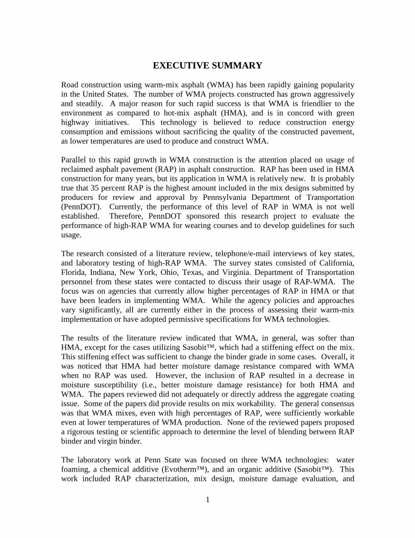
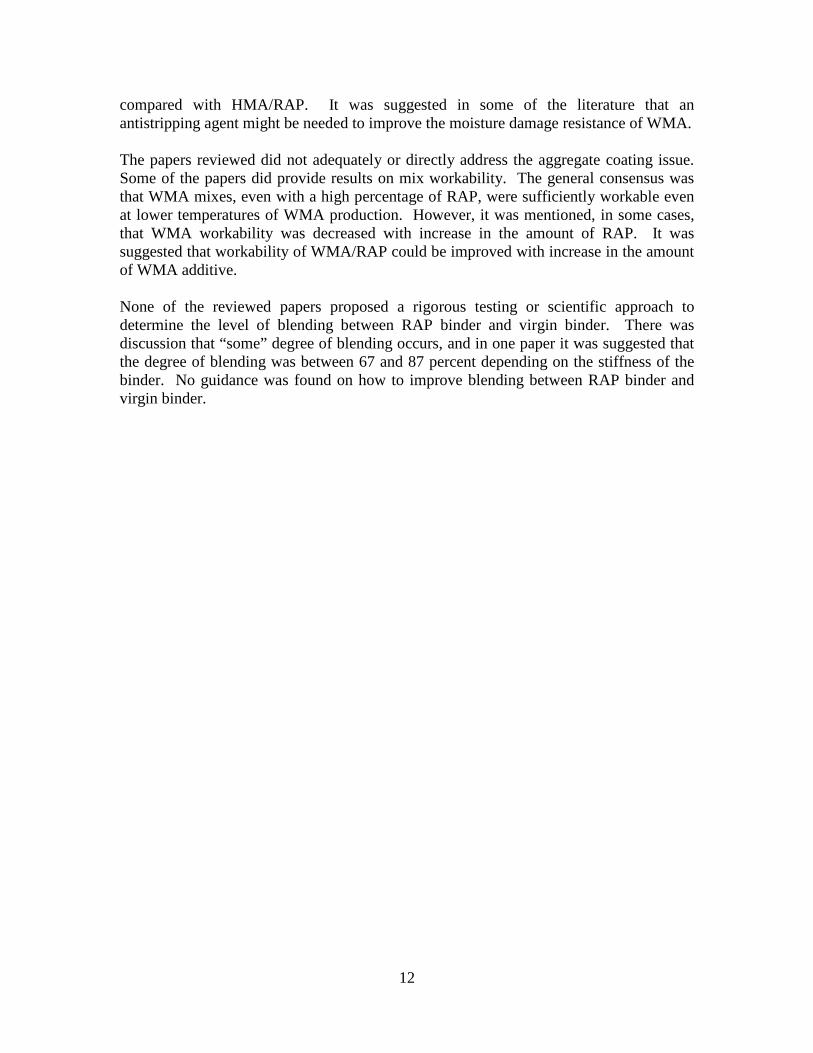
rutting evaluation using the Superpave Shear Tester (SST) and Model Mobile Load Simulator Third Scale (MMLS3). An extensive amount of laboratory testing was conducted considering the relatively short period of time allocated to this project, which began in January 2011 and ended in November 2011. The experiment was limited in terms of the type of materials, number of WMA additives, application rates of additives, and mixing and compaction temperatures. Only one aggregate source (dolomite limestone), one virgin binder (PG 64-22), and one RAP source were utilized in this research. Hot-mix asphalt concrete with no RAP was included in the study as a control mix. Two RAP contents, 15 percent and 35 percent, were utilized. WMA additive application rates were selected based on manufacturer’s recommendations, relevant information from the literature, and the rates that have been used within the last few years in construction of WMA. A Superpave mix with a nominal maximum aggregate size of 9.5 mm was used throughout the research. Superpave design number of gyrations was selected as 75 applying to traffic levels of 0.3 to 3 million 18-kip equivalent single axle loads (ESALs). Design binder content for HMA at different RAP contents, established at 4 percent air voids and design number of gyrations, was used for WMA technologies. No adjustments were made to the binder content of WMA to obtain 4 percent voids. In general, it was found that for 15 percent and 35 percent RAP mixes, the air void of WMA technologies varied within a range of ±0.5 percent from that of HMA. In establishing the target gradation, full blending between the RAP binder and virgin binder was assumed in this research. RAP binder was characterized through testing and blended binder was found to have a high temperature grade of PG 70 at 35 percent RAP content. Moisture damage evaluation indicated that all mixes passed the minimum required tensile strength ratio (TSR) of 0.8, except the foaming mix at 15 percent and 35 percent RAP levels, prompting the need for usage of an antistripping agent. The chemical and organic WMA additives used in this research yielded a similar or higher TSR compared to HMA when no RAP was used or when the amount of RAP was limited to 15 percent. In the case of 35 percent RAP, both additives yielded a lower TSR, even though both passed the minimum TSR criteria. Accelerated load testing was conducted at a temperature range of approximately 42 to 50°C for 400,000 cycles of loading. The foaming mixes at both 15 percent and 35 percent demonstrated good rutting resistance and better than other mixes, which demonstrated a fair level of rutting resistance. Rutting was also evaluated using the Superpave Shear Tester through the repeated shear constant height test at a temperature of 52 °C, simulating summer pavement temperature in Pennsylvania. Based on the test results, the lowest shear strain was obtained for WMA with the Sasobit™ additive and no RAP content, and averaged 0.63 percent. The highest shear strain was observed for WMA with the Evotherm™ additive and 15 percent RAP,

3
averaging 4.8 percent. Except for this mix, the performance of other WMA showed fair to good rutting resistance. This research indicates that it is possible to produce WMA with sufficient moisture damage and rutting resistance. However, a mix design established for HMA does not necessarily produce satisfactory performance when used with WMA, and it is important that moisture damage and rutting susceptibility of WMA be evaluated for any mix design even though that mix design might have demonstrated satisfactory performance for HMA. Fatigue performance and resistance to low-temperature cracking were not evaluated as part of this research. It is particularly important to evaluate these two performance measure for both HMA and WMA mixes with high RAP content. Optimum binder content developed from HMA could be applied to WMA but air void must be checked for WMA at the design number of gyrations to ensure it does not differ significantly from the HMA design air void. A difference of no more than ±0.75 percent is recommended. Larger differences require adjustments to the binder content. Measures should be taken to fix the mix deficiencies in case performance requirements are not satisfied. In case the mix does not demonstrate the required level of moisture damage resistance, the use of liquid antistripping or hydrated lime might eliminate the problem. In case of poor rutting susceptibility, changes in gradation, reduction in binder content, or reduction/increase of WMA additive application rate are the factors that could be considered. The WMA additive application rate should not be reduced below the manufacturer’s recommended rate.

4
CHAPTER ONE: INTRODUCTION
Background Since its introduction in the United States in early 2000, warm-mix asphalt (WMA) has been rapidly gaining popularity. Several states have implemented this technology on a number of their construction projects in lieu of hot-mix asphalt (HMA) within the last several years. The number of WMA projects constructed has grown aggressively and steadily. A major reason for such rapid success is that WMA is friendlier to the environment as compared to HMA and is in accordance with green highway initiatives. This technology results in reduction of both energy consumption and emissions because of the use of lower temperatures during production and construction. Another major advantage of this technology is the possibility of extending the construction season for cold regions, because of the ability to place and compact the WMA at a lower temperature. The importance of this new technology is well recognized within the asphalt industry, state highway agencies, and the Federal Highway Administration (FHWA). The great potential of WMA technology to dominate production and construction of flexible pavement materials in the years to come is the reason the National Cooperative Highway Research Program (NCHRP) initiated several research projects on WMA, based on the research needs identified by the WMA Technical Working Group. The WMA Technical Working Group was formed by the National Asphalt Pavement Association (NAPA) and FHWA to evaluate WMA technologies. Parallel to the success noticed with the development of WMA construction is the success of using recycled asphalt materials in pavement construction, due to major cost savings and environmental benefits. In some states, using up to 15 percent of reclaimed asphalt pavement (RAP) in asphalt construction has been a norm for many years. Using higher percentages of RAP in HMA has been exercised in many instances. In Pennsylvania, fewer than 50 percent of mixes contained RAP before the year 2008; the trend began to change in that year, and a majority of mixes now contain RAP. Now that WMA is gaining wider acceptance, RAP is being utilized in WMA in some construction projects. The work and data presented in this report are the result of a research project sponsored by PennDOT to focus on evaluating the feasibility of using high RAP contents in WMA, and on determining the laboratory performance of WMA pavements containing a high percentage of RAP. The final objective was to develop draft guidelines for usage of high percentages of RAP in WMA in Pennsylvania. These guidelines are presented in Appendix E.

5
Work Plan The general research approach, the testing plan, and the sequencing of project tasks are presented in the flowchart presented in Figure 1. The first major activity of the project was to gather useful information from state highway agencies and contractors regarding design and construction of WMA pavements with high RAP content, and information from existing literature on this issue. This was followed by selecting a series of WMA technologies and high RAP contents and conducting a laboratory evaluation and testing program. The results were utilized in developing draft guidelines for usage of high RAP with WMA. Following are brief descriptions of the completed tasks.
Figure 1. Flow Chart of Tasks
Task 4: Interim Report on Survey of States and Literature Review
Task 8: Final Report
Task 1: Survey of Agencies on WMA/RAP Design and Construction
Task 2: Review Basic and Applied Research on WMA Pavements with RAP
Task 3: Development of Experimental Plan
Task 5: Procurement of Materials
Task 6: Conduct Experimental Plan
Task 7: Development of Draft Guidelines and Draft Specifications for Usage of High RAP Content in WMA

6
Task 1: Survey of Agencies on WMA/RAP Design and Construction As mentioned previously, WMA was introduced into the United States less than a decade ago. Despite its relatively young age in this country, WMA technology has been used in construction of a considerable number of pavements in different states. A survey was conducted of several states to determine the experience gained, the technologies used, and the observed performance. This survey was conducted through phone conversations with state representatives and through e-mail correspondence. The results of the survey were provided to PennDOT in March 2011. A summary of the survey results are presented in Chapter Two.
Task 2: Review Basic and Applied Research on WMA Pavements with RAP The research team conducted a thorough literature search on using RAP with WMA. The core of this task was a critical review of the literature on basic and applied research conducted on WMA/RAP design and construction. A brief summary of the literature review is provided in Chapter Two. Additional details were provided in the interim report to PennDOT in March 2011.
Task 3: Develop Experimental Plan for Laboratory Investigation An experimental plan was developed and submitted to PennDOT in April 2011. The plan included the following items:
• WMA technologies to be included • The type and amount of materials • Equipment and test procedures • Testing matrix for each step of the laboratory investigation
Task 4: Submit Interim Report An interim report was submitted to PennDOT in March 2001. This report included the following items: 1. Summary of surveyed state highway agencies and provinces regarding WMA/RAP
pavements 2. Summary of literature review regarding WMA/RAP pavements
Task 5: Procurement of Materials Under this task, materials needed for testing were procured, including:
• Aggregates • Asphalt binder • WMA additives

7
• RAP Penn State was responsible for the procurement of aggregates, asphalt binders, and WMA additives. PennDOT procured and delivered the RAP material to Penn State.
Task 6: Conduct Experimental Plan Developed in Phase I Under this task, the developed and approved experimental plan was implemented. Details of this testing plan are provided in Chapter Three.
Task 7: Develop Draft Guidelines for Usage of High RAP with WMA Technology Results from this research provided the basis for the development of draft guidelines for usage of high RAP in WMA construction. The draft guidelines were provided to PennDOT in October 2011 and are reported in the Appendix of this report. Task 8: Final Report The final project task was the preparation of this final project report.

8
CHAPTER TWO: SURVEY OF STATES AND LITERATURE REVIEW
Survey of Agencies on WMA/RAP Design and Construction An informal survey was conducted of selected lead states to determine the experience gained, the technologies used, and the observed performance from their WMA projects through 2010. This survey was conducted through phone conversations with state representatives and through e-mail correspondence, and is summarized in the following paragraphs. Experiences between agencies have varied significantly, largely dependent upon other relevant policies and practices in the states. Additional details are available in the interim project report. Since 2006, the California Department of Transportation (CALTRANS) has completed 18 WMA projects, including a project on Interstate 5, with 8 to 10 additional projects planned for 2011. Technologies tested include Advera™, Astec Double Barrel® Green, MAXAM, Gencor, Evotherm™, Sasobit™ and Rediset WMX. Prior to 2011, CALTRANS has only used WMA in surface pavement preservation layers, and compaction temperatures have only been dropped by approximately 25 °F. The CALTRANS specification currently allows alternate the use of Evotherm™, Advera™ or Sasobit™, although the agency plans to move to a permissive specification contract. CALTRANS has mandated the use of some percentage of rubber and also utilizes a lot of polymer-modified binders. Rubber is temperature sensitive, and thus WMA has positive potential, but this is balanced by limitations on lowering the temperature too much with the polymer-modified binders. To date, CALTRANS has not allowed the use of RAP in warm mix. The Florida Department of Transportation (FDOT) first used WMA in 2006, but has constructed only 439,000 tons of WMA through 2010; there has not been widespread buy-in from Florida contractors. The approach has been to design WMA as HMA, and then to add the warm-mix additive at the plant. Water-injection foaming is the most popular in Florida, but Eco-Foam II, Aspha-min, Astec Double Barrel® Green System, Evotherm™ DAT, Meeker Aqua Foam, and Terex WMA System have been approved. The ambient air temperature requirements are lowered by 5 °F for WMA. The comparative mixing and compaction temperatures for all projects have been compiled by FDOT, indicating reductions in mixing temperature varying up to 75 °F, with 40 °F being fairly typical. Until two years ago, FDOT did not allow RAP in any friction courses. FDOT does not have tracking of WMA with RAP, as the agency is not treating it differently from HMA and has no additional restrictions on RAP in WMA. In 2009, Indiana DOT (INDOT) tried one or two of the WMA chemicals but had issues and concerns; the agency could not get densities and compaction, and found that it added to the cost of the mix. Therefore, INDOT decided to only use direct water foaming pending further national research, and only on roadways with less than 10 million ESALs, although INDOT is constructing one or two pilot projects on roads with higher

9
traffic. Indiana has about 100 certified plants, and 30 percent of those have foaming equipment. Temperatures at production are 280 to 300 °F, which is slightly below HMA; they are not focused on fuel savings, but rather on good coating and good compaction for cases where the haul time is as long as an hour. In 2010, INDOT changed its RAP specification for use in both HMA and WMA to switch from controlling percent RAP based on mass of mix to controlling percent RAP based on mass of binder. The binder of the RAP is limited to a maximum of 40 percent for base and binder courses, 25 percent for open-graded mixes, 40 percent for lower-traffic dense-graded surface courses, and 15 percent for higher-traffic surface courses. INDOT has reported excellent coating with 25 percent binder replacement in WMA; most contractors find binder replacements over 25 percent less cost-effective due to the premium binders needed. New York (NYSDOT) started using WMA in 2006 with two technologies, Sasobit™ and LEA (Low Emission Asphalt). In 2010, usage increased from the previous years, with the technologies including LEA, LEA Lite and Terex Foaming. With LEA, the agency has had temperatures drop to about 210 °F. With Evotherm™, reductions have been around 40 °F from HMA levels. With LEA Lite, they could go down to 250 °F. RAP limits in HMA in New York are 20 percent maximum for wearing and binder courses and 30 percent maximum for base layers. In one case of LEA, 20 percent RAP was used, without other changes in the process. The RAP was introduced wet at the same time as the wet sand. TSR (tensile strength ratio) was acceptable, and performance has been good to date. In 2006, Ohio (ODOT) first started using WMA on low-volume roads with three technologies: Sasobit™, Evotherm™ and Advera™. In 2008, a set of specifications for foaming was developed, but limited WMA construction was performed. In 2009, foaming was used on non-heavy duty roads, but not allowed in SMA. However, in 2010, usage increased drastically when WMA was allowed on heavy duty roads. With foaming, ODOT has reduced temperatures by 25 to 35 °F from HMA temperatures and has seen significant reductions in emissions. It is believed that the problems that have been observed on WMA are not related to RAP. RAP limits in Ohio for HMA depend on the magnitude of jobs and other factors, allowing 10 to 25 percent for wearing courses, 35 to 40 percent for binder layers, and 40 to 50 percent for the base layers. Typical usage has been 20 percent for wearing courses, 30 to 35 percent for binder courses and 35 to 40 percent for base layers. Ohio DOT has used RAP with WMA foaming technology, but not with other WMA additives. Texas Department of Transportation (TXDOT) has been increasing the usage of WMA drastically, from 2000 tons in 2008 to over a million tons in 2010. WMA is now allowed or required on all projects. Texas has been using WMA with both dense-graded mixes as well as Stone Mastic Asphalt. Hamburg wheel tracking results on Texas WMA have shown more rutting and moisture damage potential compared with HMA, but there is no field evidence of inferior performance. TXDOT has also investigated laboratory design of WMA, showing that the asphalt content is reduced by about 0.5 percent. While there are about 12 WMA technologies approved, the ones mainly used include Evotherm™, Astec's Double Barrel® Green Foaming, and Advera™. The current recommendation is

10
to continue designing as HMA to prevent reduction in asphalt content. The maximum RAP allowed in TXDOT mixes for wearing, binder, and base courses are 20 percent, 30 percent, and 40 percent, respectively. Texas has constructed many projects with WMA/RAP, mostly with 20 percent RAP with chemical WMA additives. The only change for using RAP with WMA was the increase of dwell time in the drum, to ensure proper coating and mixing. Virginia DOT allowed WMA through special provisions until 2010, but is now utilizing a permissive specification. An estimated 40 to 50 percent of 2010 and 2011 asphalt paving is WMA, but it is only tracked on the weigh tickets. An estimated 60 to 75 percent are running foaming equipment, and many are leaving the foaming on for all mixes as a compaction aid. The specification allows compaction temperature reduction. The base temperature must be above 4.4 °C (40 °F). For the mix, the manufacturer’s recommendations can be followed, and the requirements are simply that the mix has to meet the specifications for density and tensile strength ratio (TSR). In Virginia, RAP is used in almost all asphalt pavements, including stone-mastic warm-mix asphalt. Up to 20 percent RAP is permitted without exception, with 20 to 30 percent RAP considered high, and allowing the use of a binder credit (reducing the high temperature grade of the virgin binder by one grade). The result of the combination of the permissive specification for warm mix, and the extensive use of RAP, means that many warm mix projects were constructed in 2010 containing 10 to 20 percent RAP, and some with up to 30 percent RAP. Temperature drops of around 50°F or more have been noted on some trial projects, with density and ride requirements met. However, on many projects, especially with polymer-modified binders, the contractors are only dropping the temperatures by 25 to 35°F.
Review Basic and Applied Research on WMA Pavements with RAP A brief summary of relevant literature regarding areas of consideration for usage of the WMA/RAP combination is provided in this section. Attention was focused on the following important aspects:
• The degree of binder blending, or how well the RAP binder blends with the virgin binder, is not new and is applicable to all circumstances where RAP is introduced into hot-mix asphalt or warm-mix asphalt. This becomes a greater concern as the amount of RAP introduced into the mix is increased.
• Specific temperatures to be used during mixing and compaction are recommended
for certain WMA technologies. Would usage of high RAP content in WMA require altering WMA production temperatures in any way?
• The RAP may affect the amount of WMA additive, since the RAP binder is
highly aged with high modulus. As the amount of RAP is increased, would it require increasing the amount of WMA additive, and if so, would this increase

11
adversely impact performance, and what limits should be observed when such an increase in additive amount is needed?
• The fact that WMA can be produced at a lower temperature than HMA is because
the binder’s ability to coat, and mix workability and mix compactability are not sacrificed as a result of lower temperatures (through additives or foaming). Is there an upper limit to the amount of RAP that could be included in WMA to maintain binder coating ability, mix workability, and mix compactability?
• The success of WMA depends on whether it is a mix that can deliver performance
better or at least equal to the performance of HMA. It is important to evaluate how the mix stiffness and performance are affected as high RAP content is used in WMA mixes.
• Work within the past several years on WMA has indicated that laboratory
performance of WMA has been inferior to HMA in regard to moisture damage, but there is no supporting field evidence. Would increases in the RAP content potentially improve moisture damage resistance of WMA?
The existing literature on WMA/RAP was investigated with the preceding concerns and questions in mind. The findings from this literature search are briefly summarized below, with additional details in Table 1 of the interim report. The literature review included 10 research projects on laboratory performance of WMA and RAP. The type of non-foaming technologies included in these research projects was limited; the most common non-foaming additive considered in most of the papers reviewed included Sasobit™. Other than direct water foaming, Advera Zeolite was the second most common additive researched behind Sasobit™. The maximum RAP content of the mix in two of the research projects was 100 percent, although most of the research projects had maximum RAP content of 30 to 40 percent.
Laboratory evaluation included a wide range of tests including dynamic modulus, flow number, indirect tensile, Hamburg Wheel Tracking, Asphalt Pavement Analyzer, resilient modulus, seismic modulus, and a series of moisture damage tests. Two of the papers also addressed field construction of the laboratory investigated mixes. In general, the results indicated that RAP stiffens the mix, as expected. Both HMA and WMA with RAP were stiffer and had higher tensile strength compared with HMA and WMA without RAP. The results also indicated that WMA, in general, was softer than HMA except for the cases with Sasobit™, which had a stiffening effect on the mix. This stiffening effect was sufficient to change the binder grade in some cases. Overall, it was noticed that HMA had better moisture damage resistance compared with WMA when no RAP was used. However, inclusion of RAP resulted in a decrease of moisture susceptibility (i.e., better moisture damage resistance) for both HMA and WMA. Furthermore, this RAP addition improved the moisture damage resistance of WMA to a point where, in some cases, better performance of WMA/RAP was observed
12
compared with HMA/RAP. It was suggested in some of the literature that an antistripping agent might be needed to improve the moisture damage resistance of WMA. The papers reviewed did not adequately or directly address the aggregate coating issue. Some of the papers did provide results on mix workability. The general consensus was that WMA mixes, even with a high percentage of RAP, were sufficiently workable even at lower temperatures of WMA production. However, it was mentioned, in some cases, that WMA workability was decreased with increase in the amount of RAP. It was suggested that workability of WMA/RAP could be improved with increase in the amount of WMA additive. None of the reviewed papers proposed a rigorous testing or scientific approach to determine the level of blending between RAP binder and virgin binder. There was discussion that “some” degree of blending occurs, and in one paper it was suggested that the degree of blending was between 67 and 87 percent depending on the stiffness of the binder. No guidance was found on how to improve blending between RAP binder and virgin binder.

13
CHAPTER THREE: EXPERIMENTAL PROGRAM
Experimental Plan The major part of this research project was laboratory evaluation of WMA-RAP. This chapter covers the activities associated with this portion of the research. In general, the laboratory work included selection and procurement of materials and conducting all necessary tests. The tests included the following:
• Gradation determination for both RAP aggregate and virgin aggregate • Determination of specific gravities of RAP aggregate and virgin aggregate • Asphalt content determination for the RAP • Characterization of virgin and RAP binders • Mix design • Moisture damage evaluation • Accelerated rut testing using MMLS3 • Permanent shear deformation evaluation
During development of the laboratory experimental plan, the following issues were addressed, in consultation with PennDOT:
• Specific WMA technologies to be included. • RAP, virgin aggregate, and binders considered for this research. • Equipment and procedures needed to conduct testing.
WMA Technologies The following three WMA technologies were considered in this research.
• Water foaming • EvothermTM • SasobitTM
In the foaming process, water was used to foam the asphalt. Penn State acquired water foaming equipment from Pavement Technology Incorporated. This piece of equipment was used in this research to prepare the foamed specimens. Evotherm™, from MeadWestvaco Corporation, is a chemical additive and was blended with the asphalt binder in the laboratory. Sasobit™ is an organic (waxy) additive from Sasol Wax North America Corporation and was blended with the asphalt binder in the laboratory.
Materials The reclaimed asphalt pavement material used in this project was from Glenn O. Hawbaker, Inc (GOH), and was stockpiled at the Penn State Asphalt Laboratory. This RAP is from material stockpiled at GOH’s Pleasant Gap bituminous production facility.

14
The virgin aggregate was dolomite limestone from the Curtin Gap aggregate quarry of HRI, Inc. This aggregate has PennDOT skid resistance level (SRL) designation M (for highways with annual daily traffic of 1000 to 3000). The binder was from the United Refineries Terminal at Warren, Pa., and was graded as PG 64-22. Table 1 presents a summary of the materials and sources.
Table 1. Materials Used in This Research Project
Material Source Quantity Month Received Aggregates HRI 2,000 lb October 2010
RAP GOH 1,150 lb October 2010
Sasobit™ Additive
Sasol Wax North America 15 lb April 2011
Evotherm™ Additive
MeadWestvaco 30 fl oz April 2011
PG 64-22 Asphalt Binder
United Refineries, Warren, PA
20 gal December 2010, May 2011
Additive Application Rates and Temperatures Application rates for both Evotherm™ and Sasobit™ were selected based on general guidelines provided by the additive manufacturers as well as based on what was found in the literature regarding past research. Similarly, temperatures for mixing and compaction were decided based on past research and available information. The researchers did not find any specific directions regarding the application rate of additives depending on the type of binder or the amount of RAP in the mix. The researchers for this project believed that, in general, the amount of these WMA additives must be probably increased as the amount of RAP is increased. The reasoning for this belief is that RAP tends to stiffen the mix and the WMA additives tend to provide more fluidity (workability) of the mix. Table 2 presents the application rates and temperatures used in this research.
Mix Type and RAP Content A Superpave 9.5-mm gradation was used for this research. The RAP content was established at zero percent, 15 percent, and 35 percent. RAP and virgin aggregate were blended at temperatures that were determined based on manufacturers’ recommendations and literature reviewed in this research. This was followed by introduction of the virgin binder modified with WMA additive. The amount of virgin binder to be added was decided based on RAP binder content and optimum binder content. Mixing and compaction temperatures were decided based on recommendations of WMA additive providers. Mix designs were conducted by the research team for HMA. Those designs were then directly used to produce WMA. The RAP contents reported in this document

15
are based on the mass of the aggregate-RAP. Percent reported RAP will be lower if it is based on the mass of the mix. For example, 15 percent and 35 percent RAP reported based on aggregate-RAP blend in this study are 14.3 percent and 33.6 percent if reported based on the mass of the mix.
Table 2. Additive Application Rates and Mixing and Compaction Temperatures Used in This Study
Technology % RAP Additive
Application Rate, %
Mixing Temperature,
°C (°F)
Compaction Temperature,
°C (°F) Evotherm™ 0 0.4 132 (270) 121 (250) Sasobit™ 0 1.5 132 (270) 121 (250) Foaming 0 2.0 138 (280) 128 (262)
HMA 0 0.0 147 (297) 138 (280)
Evotherm™ 15 0.5 132 (270) 121 (250) Sasobit™ 15 1.75 132 (270) 121 (250) Foaming 15 2.0 138 (280) 128 (262)
HMA 15 0.0 147 (297) 138 (280)
Evotherm™ 35 0.6 132 (270) 121 (250) Sasobit™ 35 2.0 132 (270) 121 (250) Foaming 35 2.0 138 (280) 128 (262)
HMA 35 0.0 147 (297) 138 (280)
Blending Procedure The WMA additives were blended into the PG 64-22 binder in the laboratory.
The binder was originally obtained in 5-gal buckets and needed to be split into smaller quart cans for easier handling. To split the buckets, they were placed into an oven at 135 ˚C (275 °F) for between 5 and 6 hours, until the viscosity of the binder was thin enough to pour into quart cans. The cans were then labeled with the proper identification of their contents.
Steps for the Foaming Process
1. Binder was heated in the oven at a temperature of 135 °C (275 °F) for 45 minutes, to make it fluid enough for pouring.
2. While the binder was being heated, the foamer was started, and the reservoir and exit temperatures were set at 138 °C (280 °F) and 141 °C (285 °F), respectively.
3. The reservoir bag was placed and the corresponding thermocouples of the bag were attached to the foaming equipment.
4. An air pressure hose was attached to the air regulator and the pressure was adjusted to the manufacturer’s recommended level.

16
5. The water application rate (2 percent) for foaming was entered in the foamer. 6. The desired amount of foamed binder was selected. 7. At this point, the heated fluid binder was poured into the plastic bag residing
inside the reservoir of the foamer. 8. Sufficient time was allowed for the temperature of the binder and the reservoir to
establish at the target level. 9. Once the temperature of the binder and reservoir was stabilized, the foaming
process began. 10. A hot container was used to collect the foamed asphalt. 11. The foamed asphalt was immediately transported and added to the batched
material on scale to prepare the asphalt mix. Steps to Blend the Evotherm™ into the Virgin Binder
1. The size of the can and the mass of the binder for blending were selected in a way that, to the extent possible, the final blended material could be consumed once, without the need for reheating at a later time for use.
2. The mass of the binder was determined accurately. 3. The binder mass was used to determine the mass of the additive to be blended,
resulting in the target additive application rate. 4. The binder cans were placed into an oven at 135 ˚C (275 °F) for 45 minutes, until
the binder was fluid enough for pouring. 5. The hot binder can was quickly placed on a scale and the Evotherm™ additive
was added to deliver the established application rate. 6. Immediately after the addition of the additive, the can was placed on a ceramic
hot plate with temperature control. The temperature was set at a level high enough to maintain the binder fluid during blending.
7. Shear blender was utilized to stir the additive and asphalt. The blender was gradually lowered into the hot binder and shear blending was conducted for at least 30 minutes, or until the material appeared homogenous and uniform. Blending was conducted at 500 revolutions per minute (RPM).
8. The preceding steps were repeated for all three application rates using different binder cans.
9. The cans were then labeled corresponding to the percent additive applied. Steps to Blend the Sasobit™ into the Virgin Binder
1. The size of the can and the mass of the binder for blending were selected in a way that, to the extent possible, the final blended material could be consumed once, without the need for reheating at a later time for use.
2. The mass of binder was determined accurately. 3. The binder mass was used to determine the mass of the additive to be blended,
resulting in the target additive application rate. 4. The binder cans were placed into an oven at 135 ˚C (275 °F) for 45 minutes, until
the binder was fluid enough for pouring. 5. During the time the binder was heated in the oven, small tins were used to weigh
out the necessary amount of Sasobit™ for each can.

17
6. Immediately after the addition of the additive, the can was placed on a ceramic hot plate with temperature control. The temperature was set at a level high enough to keep the binder fluid during blending.
7. The blender was lowered into the hot binder and was set at 1,000 rpm, and then the Sasobit™ was slowly added. The binder and Sasobit™ blending continued until all of the Sasobit™ pellets were completely melted. Complete melting was typically observed after approximately 30 minutes from the beginning of the blending process.
8. The preceding steps were repeated for all three applications rates using different binder cans.
9. The cans were then labeled corresponding to the percent additive applied.
Equipment and Tests Water foaming was implemented using the recently purchased foamer from Pavement Technologies, Inc. Preparation of specimens for testing was conducted using equipment available at Penn State, that includes forced-draft ovens, bucket mixer, Pine gyratory compactor, and asphalt binder extraction equipment. Mechanical testing was conducted using the servo-hydraulic systems and rheometers available at Penn State. The Third-Scale Model Mobile Load Simulator was used to conduct accelerated pavement testing. The testing matrix provided in Table 3 was followed. The PennDOT-modified version of AASHTO T283 was used to evaluate the moisture susceptibility of the produced mixes. AASHTO T320 testing was used to evaluate the rutting potential of the mixes. Finally, accelerated pavement testing with MMLS3 was used to evaluate rutting susceptibility of these mixes under trafficking. MMLS3 testing was limited to 15 percent and 35 percent RAP mixes, and while only two of the three WMA additives were planned to be included due to budget and time constraints, all three WMA technologies were included in the final testing.
Table 3. Testing Matrix to Evaluate the Effect of RAP Content on WMA Properties
Test Procedure
No. of RAP
Contents
No. of WMA Technologies
HMA
No. of Tests per
Group
No. of Specimens Per Test
Total No. of
Specimens AASHTO
T283 Modified (1)
3 3 1 9 6 72
AASHTO T320(2) 3 3 1 1 2 24
MMLS3(3) 2 3 0 2 9 18
1. Modified procedure of T283 based on PennDOT Bulletin 27 was used except targeting a saturation level between 70 and 80 percent.
2. Determining the Permanent Shear Strain Using Repeated Shear Constant Height Test 3. Model Mobile Load Simulator-Third Scale

18
RAP Characterization Determination of RAP aggregate and binder properties and binder content were required before determination of the required virgin aggregate gradation and binder content.
RAP Extraction Extraction of the RAP binder was achieved using centrifuge extraction according to Pennsylvania Test Method (PTM) 702 Method A (Quantitative Extraction of Bitumen from Bituminous Paving Mixtures). Extraction was conducted on the RAP material after the material larger than 12.5 mm was scalped off the RAP. The extraction process uses a centrifuge and solvent to dissolve and extract the asphalt from a sample. The procedure requires a centrifuge, solvent, container for catching the solvent, filter ring, and other standard laboratory equipment to perform the test method. To begin, the test sample, filter, and empty ignition dish are weighed, and the values are recorded. Next, the test sample is placed into the centrifuge bowl and covered with the solvent. Enough time is allowed for the sample to be dissolved. After the sample has been dissolved, the filter is placed on the bowl and covered tightly with the lid. A container is placed to catch the solvent beneath the drain of the centrifuge. The centrifuge is started slowly, and the speed is gradually increased to the maximum of 3,600 rpm, until the solvent ceases to flow from the drain. After the centrifuge has stopped rotating, an additional 200 mL of solvent is added, and the extraction continues. Additional solvent should be added in 200 mL quantities until the extract is clear and not darker than a light straw color. Once the extract is clear in color, the filter ring is removed from the bowl and is allowed to air dry. After air drying, the mineral matter is removed from the filter ring to the extent possible, and is placed into the centrifuge bowl with the aggregate. Then, the filter ring is placed into an oven at 163 °C and is dried to a constant mass, after which its weight is recorded. Next, the collected extract solvent is agitated, and a 100-mL aliquot is measured and placed into the ignition dish. First, the ignition dish is dried on a hot plate; then, it is burned at a dull, red heat at 600 °C, cooled, and weighed, and then 5 mL of saturated ammonium carbonate solution is added per gram of the ash. The mixture is then digested at room temperature for 1 hour, then placed into an oven at 110 °C to dry, and then cooled in a desiccator and weighed to 0.001 g. Finally, the volume of the extracted solvent solution and the mass of the extracted mineral matter are recorded.
RAP Binder Recovery Once extraction was completed, the binder was recovered using a rotary evaporator according to ASTM D5404 (Standard Practice for Recovery of Asphalt from Solution Using the Rotary Evaporator). In brief, the binder is recovered from the solution by using a rotary evaporator to evaporate, condense, and then recover the solvent in a separate flask. The binder remains in the distillation flask. First, an oil bath is heated to 140 °C (284 °F) , and water is circulated through the condenser. A 500-mL sample of the solvent solution is added to the distillation flask and then is attached to the evaporator. Next, a vacuum is applied at 5.3 kPa, and a nitrogen flow of 500 mL/min is added to the system. The distillation flask is then lowered into the hot oil bath and begins to rotate

19
until most of the solvent solution is evaporated, and then an additional 500-mL sample of the solvent solution is added. This procedure is repeated until all of the solvent solution has evaporated. After the bulk of the solvent has been distilled from the asphalt and no noticeable condensation is occurring in the condenser, the flask is then immersed to a depth of 1.5 inches, a vacuum is applied at an increased pressure of 80.0 kPa, and the nitrogen flow is increased to 600 mL/min. This is applied for a total of 15 minutes, after which the asphalt is poured into containers for storage.
RAP Aggregate Gradation and Binder Content Using Ignition Oven After scalping the RAP of any material retained on the 12.5-mm sieve and above, the binder content of the RAP was obtained by PTM 757 (Determination of Asphalt Content and Gradation of Mixtures by the Ignition Method). This test method covers the determination of asphalt content of bituminous mixtures by the ignition of the asphalt binder at 538 ± 5°C (1000 ± 9°F) in a furnace, and is a modification of AASHTO T308. The aggregate remaining after burning can be used for the sieve analysis using AASHTO T30. The asphalt binder in the bituminous mixture is ignited using the furnace equipment applicable to the particular method. The asphalt content is calculated as the difference between the initial mass of the bituminous mixture and the mass of the residual aggregate, any calibration factor(s) and moisture content. The calibration factor for RAP binder content was assumed to be 0.5 based on guidelines provided in PennDOT Bulletin 27 and PTM 757 for RAP material. The asphalt content is expressed as a mass percentage of the moisture-free mixture.
RAP Binder Aging Using the Rolling Thin Film Oven In situations where short-term aging was needed, the asphalt binders were aged in accordance with AASHTO T240, Standard Method of Test for Effect of Heat and Air on a Moving Film of Asphalt “Rolling Thin Film Oven Test” (RTFO). RTFO consists of an oven chamber that houses a vertical circular carriage (Figure 2a). The carriage, which holds eight RTFO specimen bottles (each contains 35 g of binder, Figure 2b), rotates about its center. A single air jet is located in the oven. Hot air, at a temperature of 163 °C, is blown into the center of each RTFO bottle as it passes in front of the jet. A fan continually circulates the air within the oven chamber. This exposure to hot air continues for 85 minutes.
Figure 2. (a) Rolling Thin Film Oven (RTFO), (b) Binder Bottles at Different Stages

20
RAP Binder Stiffness Using Dynamic Shear Rheometer The Dynamic Shear Rheometer (DSR, Figure 3) measures shear complex modulus G* and phase angle δ by measuring the shear strain response of the specimen to a torque, as shown in Figure 4. Before performing any DSR tests, the binder from the RAP was extracted and recovered using PTM 702 Method A and ASTM D5404. The binder was first tested at high temperature using original unaged binder settings. To determine the critical high temperature, Tc(High), the following equation was used:
𝑇𝑐(𝐻𝑖𝑔ℎ) = �log( 1.00) − log(𝐺1)
𝑎� + 𝑇1
(1)
where G1= the G*/sin 𝛿 value at a specific temperature, T1, and α = the slope of the stiffness-temperature curve. Next the remaining binder was RTFO aged and then tested using RTFO-aged settings. To determine the critical high temperature, Tc(High), for the RTFO binder, the following equation was used:
𝑇𝑐(𝐻𝑖𝑔ℎ) = �log( 2.20) − log(𝐺1)
𝑎� + 𝑇1
(2)
where G1= the G*/sin 𝛿 value at a specific temperature, T1, and α = the slope of the stiffness-temperature curve. The values from both Tc(High) equations were compared and the lower of the two values was used to determine the Tc(High) of the binder. This value was then used to determine the performance grade of the recovered RAP binder. Next, the intermediate temperature DSR testing was performed on the RTFO-aged binder. To determine the critical intermediate temperature, Tc(Int), for the binder, the following equation was used:
𝑇𝑐(𝐼𝑛𝑡) = �log( 5000) − log(𝐺1)
𝑎�+ 𝑇1
(3)
where G1= the G*sin 𝛿 value at a specific temperature, T1, and α = the slope of the stiffness-temperature curve.

21
Figure 3. Dynamic Shear Rheometer (DSR)
Figure 4. Loading Configuration in DSR
RAP Binder Stiffness Using Bending Beam Rheometer The Bending Beam Rheometer (BBR, Figure 5) is used to characterize the low-temperature stiffness properties of binders. It measures the creep stiffness (S) and logarithmic creep rate (m). These properties are determined by measuring the response of a small binder beam specimen to a creep load at low temperatures (Figure 6). After finding the Tc(High) and Tc(Int) temperatures of the RAP binder, the RTFO-aged binder was tested using the BBR to determine the critical low temperature. To determine the critical low temperature Tc(S), the following equation was used:
𝑇𝑐(𝑆) = �log( 300) − log(𝑆1)
𝑎� + 𝑇1
(4)

22
where S1 = the S-value at a specific temperature, T1, and α = the slope of the stiffness-temperature curve. Also, the critical low temperature, Tc(m), was calculated using the m-value, using the following equation:
𝑇𝑐(𝑚) = �0.300 −𝑚1
𝑎� + 𝑇1
(5)
where m1 = the m-value at a specific temperature, T1, and α = the slope of the curve. The values from Tc(S) and Tc(m) were compared and the higher of the two critical temperatures was chosen to represent the low critical temperature, Tc(Low), for the recovered binder.
Figure 5. Bending Beam Rheometer
Figure 6. Loading Configuration and Response in Bending Beam Rheometer

23
Mix Design The mix design was conducted according to the PennDOT Bulletin 27 requirements in the AASHTO procedures: Practice R35, Specification M323, and Density Determination using Superpave Gyratory Compactor T312. The design number of gyrations was established at 75. A Superpave 9.5-mm gradation was used for all the mixes. Once optimum binder content was established at 4 percent air voids for HMA, the same asphalt content was used for all WMA regardless of the air void obtained at 75 gyrations. It was discussed that three RAP levels were considered: zero percent RAP (the control mix), 15 percent RAP, and 35 percent RAP. Mix gradations for the established RAP contents and gradation plots are shown in Table 4 and Figures 7 through 9, respectively.
Table 4. Mix Gradations for 0% RAP, 15% RAP and 35% RAP
Percent Passing Sieve
0% RAP 15% RAP
85% V. AGG.
35% RAP
65% V. AGG.
Target
2" 50.0mm V. AGG. 100.00 100.00 100.00 100.00 100.00 1 1/2" 37.5mm 100.00 100.00 100.00 100.00 100.00 100.00
1" 25mm 100.00 100.00 100.00 100.00 100.00 100.00 3/4" 19mm 100.00 100.00 100.00 100.00 100.00 100.00 1/2" 12.5mm 100.00 100.00 100.00 100.00 100.00 100.00 3/8" 9.5mm 95.00 92.80 95.39 92.80 96.18 95.00 #4 4.75mm 74.80 70.80 75.51 70.80 76.95 74.80 #8 2.36mm 44.50 49.99 43.53 49.99 41.54 44.50 #16 1.18mm 28.35 34.99 27.18 34.99 24.77 28.35 #30 0.6mm 19.50 25.10 18.51 25.10 16.48 19.50 #50 0.3mm 12.25 18.08 11.22 18.08 9.11 12.25 #100 0.15mm 8.20 14.28 7.13 14.28 4.93 8.20 #200 0.075mm 5.65 11.20 4.67 11.20 2.66 5.65

24
Figure 7. Gradation Plot for Zero Percent RAP Mixes
Figure 8. Gradation Plot for 15 Percent RAP Mixes
0
10
20
30
40
50
60
70
80
90
100%
Pas
sing
Sieve Opening (Raised to 0.45 Power), mm)
100% Virgin Aggregate
Max. Density Line
Combined Gradation
Control Points
R. Zone upper limit
R. Zone lower limit
12.59.54.762.361.180.30.075
0
10
20
30
40
50
60
70
80
90
100
% P
assin
g
Sieve Opening (Raised to 0.45 Power), mm)
15 % RAP and 85 % Virgin Aggregate
Max. Density Line
Combined Gradation
Control Points
R. Zone upper limit
R. Zone lower limit
RAP
Virgin. AGG.
12.59.54.762.361.180.30.075

25
Figure 9. Gradation Plot for 35 Percent RAP Mixes
After establishing the target gradation, the optimum binder content was determined for HMA at different RAP contents. For this purpose, three replicate specimens of HMA mixes at trial asphalt contents for 0 percent RAP, 15 percent RAP, and 35 percent RAP were prepared and compacted at the design number of gyrations. The mixing temperature was set at 147 °C (297 °F), while the compaction temperature was set at 137 °C (279 °F), for these HMA mixes. For all mixes, the same binder, a PG 64-22 from United Refineries, was used. Based on the test results, the optimum binder contents for 0 percent RAP, 15 percent RAP and 35 percent RAP were determined to be 5.4 percent, 5.6 percent, and 5.8 percent, respectively, by the weight of total mix. Three batches of virgin aggregate and RAP material were prepared for each mix. Virgin aggregate batches were conditioned at mixing temperature in the oven overnight. RAP material was placed in the oven at 110 °C (230 °F) for 2 hours before blending. Virgin binder was placed in the oven approximately 1.5 hours before mixing with the virgin aggregate and RAP material. RAP and virgin aggregate were blended at mixing temperatures, followed by introduction of the virgin binder. The amount of virgin binder to be added was decided based on the RAP binder content and optimum binder content. Table 5 shows the number of specimens prepared for each mix and the corresponding asphalt content.
0
10
20
30
40
50
60
70
80
90
100
% P
assin
g
Sieve Opening (Raised to 0.45 Power), mm)
35 % RAP and 65 % Virgin Aggregate
Max. Density Line
Combined Gradation
Control Points
R. Zone upper limit
R. Zone lower limit
RAP
Virgin. AGG.
12.59.54.762.361.180.30.075

26
Table 5. Testing Matrix for Mix Design
RAP, %
AC, %
Testing Matrix (No. of Specimens) HMA Evotherm Sasobit Foaming
0 5.8 3 3 3 3 0 5.4 3 3 3 3
15 5.6 3 3 3 3 35 5.8 3 3 3 3
Bulk specific gravity of compacted specimens was measured after leaving the specimens at room temperature overnight. Afterwards, indirect tensile test (IDT) was conducted to determine the indirect tensile strength (ITS) for each specimen using INSTRON 5583 test equipment. After IDT, one of the three specimens was broken loose to determine maximum theoretical specific gravity. Test results for air void and strength for each specimen and each mix are presented in Appendix A.
Evaluation of Moisture Susceptibility (Resistance to Moisture Damage) The moisture damage resistance of the mixes was evaluated according to the modified version of AASHTO T283, as detailed in PTM Bulletin 27. WMA additive application rates, RAP contents, asphalt contents, and gradations, as established during mix design, were used in preparing specimens for moisture damage evaluation. Preparation of specimens for the testing was conducted using equipment available at Penn State, which includes devices for mixing and compacting SGC specimens; vacuum containers with a vacuum pump, balance, and water tank for AASHTO T166; water bath with constant temperature of 60 °C (140 °F); freezer; plastic film for wrapping specimens; leak-proof plastic bags to enclose saturated specimens; and the INSTRON series 5583 loading frame. Six specimens, 150 mm in diameter and 95 mm tall, were prepared using the Superpave gyratory compactor. An additional loose specimen was prepared for determining the maximum theoretical specific gravity. Total mass of material was calculated to deliver a 95-mm tall specimen at 7 percent ± 0.5 percent air voids. Virgin aggregate, RAP, and virgin binder were proportioned to deliver the required mass for each mix. The number of specimens prepared for moisture damage evaluation is listed in Table 6.
Table 6. Testing Matrix for Moisture Damage Test
RAP, %
AC, %
Testing Matrix (No. of Specimens) HMA Evotherm Sasobit Foaming
0 5.8 7 7 7 7 0 5.4 7 7 7 7 15 5.6 7 7 7 7 35 5.8 7 7 7 7

27
It should be noted that moisture susceptibility evaluation at zero percent RAP was conducted at both 5.4 percent and 5.8 percent asphalt content (AC). Evaluation at 5.4 percent AC was conducted because this AC represented the design asphalt content. Evaluation at 5.8 percent AC, while not part of the original study, was conducted to provide additional information regarding the effect of asphalt content on moisture damage. After compaction, specimens were allowed to cure at room temperature for 24 hours. After curing, the maximum specific gravity and bulk specific gravity testing were done in order to determine the percentage of air voids. If the target air void of 7 percent ± 0.5 percent were not achieved, a new set of specimens would be prepared. The prepared specimens were divided into two subsets, each having three specimens. One subset remained dry (dry group) and the other subset underwent water conditioning (wet group). Grouping was done in a way that the average percent of air voids of the dry subset was approximately equal to that of the wet subset. Specimens of the wet group were subject to vacuum saturation, which continued until the degree of saturation was between 70 and 80 percent. For some of the specimens, it took approximately 2 hours of applying vacuum to achieve the target saturation range. The conditioned subset was then subjected to the freeze-thaw cycle before being tested for indirect tensile strength. Details of the specimen preparation and conditioning are provided in the following sections.
Specimen Preparation:
a. Batches for seven specimens for each mix were prepared. b. Batches of virgin aggregate were placed in the oven overnight, while the RAP
material was placed in the 110 °C (230 °F) oven for 2 hours before mixing. c. After mixing, the mixture was placed in the oven at compaction temperature
for 4±0.5 hours prior to compaction. The specimens were compacted to the height of 95 mm and placed at room temperature for 24±3 hours.
d. Air voids were determined and specimens were divided into two subsets. One subset was tested dry and the other was partially vacuum-saturated, subjected to freezing and thawing in hot water before testing.
Specimen Conditioning:
e. The specimens were placed in the vacuum container, resting on the spacer, and covered with at least 25 mm of water above the surface of the specimens. Vacuum of approximately 20-in Hg partial pressure provided the vacuum needed for partial saturation. A minimum of 70 percent saturation was achieved through this process.
f. Each of the conditioned specimens was covered with a plastic film and was placed in a sealed plastic bag containing 10±0.5 mL of water.

28
g. The bags were placed in a freezer at -18±3 °C (0±5 °F)for a minimum of 16 hours.
h. The specimens were placed in a 60±1 °C (140±1.8 °F) water bath for 24±3 hours.
i. After removal of the plastic bags, the specimens were placed in a water bath at 25±0.5 °C (77±0.9 °F) for 2 hours±10minutes.
j. The dry specimens were at room temperature and placed in a 25±0.5 °C (77±0.9 °F) water bath along with the conditioned specimens for 2 hours±10 minutes, with a minimum 25mm of water above their surface before being tested with the indirect tensile tester.
Indirect tensile strength of specimens was determined after completion of conditioning (Figure 10). The ratio of retained tensile strengths of the wet and dry subsets was calculated to determine whether the tested mix was resistant to moisture damage (Equation 6). If TSR was less than 0.80, the mix was considered susceptible to moisture damage. Detailed test results are listed in Appendix B.
dry
wet
ITSITS
TSR =
(6)
where ITSwet and ITSdry represent the average indirect tensile strength of the wet and dry groups, respectively.
Figure 10. SGC Specimen Set in the Loading Frame for Indirect Tensile Testing and Corresponding Loading in Diametral Direction

29
Testing with the Model Mobile Load Simulator 1/3 Scale The MMLS3, manufactured by MLS Test Systems in South Africa, is a small-scale accelerated trafficking device. It contains four pneumatic tires that can be inflated to a maximum tire pressure of 700 kPa (approximately 100 psi). For this project, the tires were inflated to between 600 and 650 kPa (approximately 87 to 94 psi). The tires move on bogies to apply unidirectional moving wheel loadings to the briquettes (trimmed SGC specimens). The suspensions of these wheels are calibrated so that during trafficking, they apply a load of 2.7 kN (607 lb) on the specimens. To run the test, SGC specimens had to be trimmed and put in the test bed. Nine gyratory compacted specimens were trimmed and placed in one row to form the track for tire loading, as shown in Figure 11. To prevent effects from the approaching and departing impacts from the wheels, specimens placed on both sides (at the two ends) were considered dummy specimens. Two thermocouples were inserted into one of the dummy specimens to monitor the pavement temperatures, one at the surface and one at the bottom of the sample. When the dummy specimens are excluded, the test track contains a total of seven actual briquettes for evaluation under loading. For this project, the seven briquettes consisted of three specimens of the Evotherm™ mix, three specimens of the foaming mix, and one specimen of the Sasobit™ mix. Due to budget and time constraints, hot-mix asphalt specimens were not included in the MMLS3 study. Although the Sasobit™ mix was not considered in the original plan, it was introduced into the MMLS3 testing as a single specimen. The MMLS3 can run the accelerated trafficking test under two different environmental conditions, wet and dry. In this project, specimens were tested under dry conditions. Testing temperatures were between 40 and 50 °C (104 to 122 °F), and trafficking continued for 400,000 cycles. The goal of the project was to evaluate the rutting characteristics of the tested mixes. Figure 12 demonstrates how the MMLS3 is positioned at the top of the test bed.

30
Figure 11. Trimmed SGC Specimens Arranged for MMLS3 Tracking
Figure 12. MMLS3 Loading System Assembled and Ready to Load Specimens

31
MMLS3 Sample Preparation Specimens used for this test were mixed and compacted under the same method used to prepare all specimens. However, the specimens were compacted to 75-mm high and were trimmed by saw in order to fit in the briquette spaces of the test bed. The briquettes obtained from SGC specimens were 105 mm wide and 150 mm long, as shown in Figure 13.
Figure 13. Dimensions of Trimmed Specimens
MMLS3 Sample Testing Raising the temperature of the track specimens was achieved through circulating hot water through an enclosed channel beneath the specimens. The circulating water is pumped back into the heater through its cycle, to maintain its high temperature. The target temperature for the specimens was 50 °C (122 °F), a typical maximum pavement temperature in Pennsylvania. Testing began only after the specimen temperatures reached the target and remained approximately constant. Temperature was recorded every 30 minutes using the datalogger. At this point, the test could be started by setting up the trafficking cycles on the control panel. Measurement of rutting using the profilometer was performed between each trafficking cycle in order to record the rutting-development process. Profile readings were measured on the third, fifth and seventh samples. Profile readings were taken at the following cycles (thousands): 0, 5, 10, 20, 50, 100, 150, 250, 300, and 400. The profilometer has a small wheel that moves across the top of the sample and is attached to an LVDT capturing the profile of the sample (Figures 14 and 15).

32
Figure 14. Profilometer Used to Measure Rut Profiles
Figure 15. Tracked Specimens after 400,000 Cycles of MMLS3 Loading.
Superpave Shear Tester An Interlaken Superpave Shear Tester (SST) was used to capture the properties of the asphalt mixtures in regard to permanent deformation. This is a closed-loop feedback, servo-hydraulic system that can induce various stress paths in the specimen through

33
application of axial loads, shear loads, and confinement pressures at controlled temperatures. There are six major components to this testing equipment: testing chamber, control and data acquisition system, environmental control chamber, air pressurizing system, load and deformation measuring transducers (load cells and LVDTs, respectively), and hydraulic system. Typical dimensions for test specimens are a diameter of 150 mm and a height of 50 mm. The environmental chamber can control the temperature in the range of 0 to 70 °C (158 °F). The Interlaken Series 3410 hydraulic motors power two actuators, each with a capacity of approximately 32 KN (7 kips). One actuator applies the vertical load, while the horizontal actuator induces the shear load by moving the shear table.
SST Specimen Preparation The first step in specimen preparation for testing with the Superpave Shear Tester is to compact specimens with diameter of 150 mm using the Superpave Gyratory Compactor. The specimens were compacted to air voids of 7±1 percent. Each compacted specimen was sawed using a circular saw and trimmed to deliver a specimen that was 50 mm in height. The specific gravity of the trimmed specimen was then measured, and the specimen was allowed to dry before gluing to the platens. The cross section of a trimmed specimen can be seen in Figure 16. A gluing device (Figure 17) was used to squeeze the specimen between the two platens while the glue cures. An epoxy-type glue, such as Devcon Plastic Steel, is employed for this purpose. The gluing device rigidly holds the platens and specimen to ensure that the platen faces are parallel. After the epoxy has cured, LVDT holding brackets are affixed to the sides of the platens. These brackets hold the horizontal LVDT as well as vertical LVDTs (Figures 18 and 19).
Figure 16. Sawed Face of 6-inch SGC Specimen for SST

34
Figure 17. Gluing Jig for Fixing Platens to the Shear Test Specimen
Figure 18. Assembly of Specimen and LVDTs for Deformation Measurement

35
Figure 19. LVDT Assembly for Measuring Shear Deformation
SST Testing Procedure The test was conducted according to AASHTO T320. A haversine load inducing a 69 kPa (10 psi) shear stress at 10 Hz was applied. Temperature of the specimen was maintained at 51-52 °C (124-126 °F) during the test. The loading time was 0.1 seconds, and the rest period between two loads was 0.6 seconds. A total of 5,000 cycles of shear load were applied for each specimen.
Platen
Specimen
Shear LVDT

36
CHAPTER FOUR: ANALYSIS, INTERPRETATION, AND FINDINGS
Characterization of Materials
RAP The largest size aggregate in the procured RAP was 1 inch (25 mm). Since the goal was evaluation of the RAP-WMA for a 9.5-mm mix, RAP was scalped over a ½-inch (12.5-mm) sieve to remove oversized particles before further processing. As discussed in Chapter Three, after the scalping process, RAP moisture content and RAP theoretical maximum specific gravity were determined in accordance with PTM 749 and AASHTO T209, respectively. The moisture content was found to be 0.24 percent and the maximum theoretical specific gravity was 2.531. RAP asphalt content was determined based on PTM 702 extraction testing and PTM 757 Method A ignition testing. PennDOT Bulletin 27 (Appendix H) requires solvent extraction for determination of RAP asphalt content when RAP content is equal to or greater than 20 percent. Both the extraction testing and ignition testing were performed on two random samples of the as-received RAP (i.e., with all sizes of material) and four random samples of the scalped RAP (i.e., black rock passing the 12.5-mm sieve). As seen in Figure 20, from extraction testing, the binder content of the finer RAP is significantly higher than that of the coarse RAP.
Figure 20. RAP Binder Content from Extractions
Similarly, as seen in Figure 21, the binder content of the as-received RAP (coarser material) is significantly lower than that of the finer RAP. Two burn-offs were performed on the RAP as received, and four burn-offs were performed after scalping the 12.5-mm black rock.
0.00.51.01.52.02.53.03.54.04.55.05.5
Extraction 1, RAP as Received
Extraction 2, RAP as Received
Extraction 3, RAP after Scalped
Extraction 4, RAP after Scalped
Extraction 5, RAP after Scalped
Extraction 6, RAP after Scalped
% B
inde
r C
onte
nt
Extractions
% Binder Content from Extractions

37
Figure 21. RAP Binder Content from Burn-Offs
The results for the scalped RAP are also shown in Table 7. The AC values shown in Table 6 for the PTM 757 were calculated after subtracting an assumed calibration factor of 0.5 and measured RAP moisture content. The RAP moisture content was determined to be 0.24 percent. RAP asphalt content for this project was determined to be 5.0 percent, as the average of all test results based on PTM 702 and PTM 757.
Table 7. Test Results from PTM 757 Method A and PTM 702
PTM 757 AC, % Average, % Std. Deviation, % Coefficient of Variation, % 1 5.56 5.11 0.33 6.49 2 4.86 3 5.16 4 4.86
PTM 702 AC,% Average, % Std. Deviation, % Coefficient of Variation, %
1 5.00 4.85 0.19 3.95 2 4.60 3 4.80 4 5.00
After determining RAP asphalt content, sieve analyses were performed on residual aggregate in accordance with AASHTO T30 in order to determine RAP gradation (Table 8). The designation “RAP 1” in the table is used to refer to the RAP as is, without removing the binder. This gradation is referred to as the “black rock” gradation. RAP 2
0.00.51.01.52.02.53.03.54.04.55.05.56.0
Burn-off 1, RAP as Received
Burn-off 2, RAP as Received
Burn-off 3, RAP after Scalped
Burn-off 4, RAP after Scalped
Burn-off 5, RAP after Scalped
Burn-off 6, RAP after Scalped
% B
inde
r C
onte
nt
Burn-Offs
% Binder Content from Burn-Offs (After Applying Correction Factor)

38
and RAP 3 refer to gradations of aggregates obtained from the extraction and ignition oven, respectively. Figure 22 includes a graph of RAP gradation. As expected, the gradations from the ignition oven and from extraction are close to each other, and considerably finer than the gradation of black rock. Gradation from the ignition process is slightly finer than the one obtained through the extraction process.
Table 8. RAP Gradation: RAP 1—Black Rock, RAP 2—Extraction, RAP 3— Ignition
Sieve % Passing
RAP 1 RAP 2 RAP 3 2" 50.0mm 100.0 100.0 100.0
1 1/2" 37.5mm 100.0 100.0 100.0 1" 25mm 100.0 100.0 100.0
3/4" 19mm 100.0 100.0 100.0 1/2" 12.5mm 100.0 100.0 100.0 3/8" 9.5mm 86.65 92.88 92.80 #4 4.75mm 52.54 68.87 70.80 #8 2.36mm 21.20 47.21 49.99 #16 1.18mm 8.00 31.71 34.99 #30 0.6mm 2.89 22.30 25.10 #50 0.3mm 1.09 16.17 18.08 #100 0.15mm 0.57 13.01 14.28 #200 0.075mm 0.27 10.47 11.20
Figure 22. RAP Gradation Plot
0 10 20 30 40 50 60 70 80 90
100
% P
assin
g
Sieve Opening (Raised to 0.45 Power), mm
RAP Gradation Plot
RAP 1
RAP 2
RAP 3
12.5 9.5 4.76 2.36 1.18 0.3 0.075

39
RAP aggregate gradation, RAP 3, obtained from the ignition testing was used throughout the project instead of RAP aggregate gradation, RAP 2, obtained from the extraction test. Two reasons led to this decision: the two gradations are very close to each other, and the ignition testing is easier in terms of time. Bulk and apparent specific gravities of RAP aggregate were also determined according to AASHTO T84 (fine portion, passing #4 sieve) and T85 (coarse portion, retained on #4 sieve). The test results are shown in Table 9.
Table 9. RAP Aggregate Specific Gravities
AASHTO T84 Bulk Specific Gravity (Gsb) 2.717 Apparent Specific Gravity (Gsa) 2.795
AASHTO T85 Bulk Specific Gravity (Gsb) 2.720 Apparent Specific Gravity (Gsa) 2.774
Virgin Aggregate The aggregate from #8 stockpiled material was used for sizes between 9.5 mm and #4; the aggregate from B3 stockpiled material was used for the aggregate sizes ranging from #8 sieve to material passing #200 sieve. The aggregate was 100 percent crushed. Specific gravities of the fine and coarse portions of the virgin aggregate are shown in Table 10.
Table 10 Virgin Aggregate Gravities
AASHTO T84 Bulk Specific Gravity (Gsb) 2.735 Apparent Specific Gravity (Gsa) 2.821
AASHTO T85 Bulk Specific Gravity (Gsb) 2.753 Apparent Specific Gravity (Gsa) 2.820
Determination of RAP Binder Grade
Results from Dynamic Shear Rheometer Testing The Dynamic Shear Rheometer (DSR) tests were conducted on the recovered RAP binder at selected high, intermediate, and low temperatures. Results of high temperature testing are shown in Figures 23 and 24. For this testing, the critical high temperature Tc(High), without any further processing of the RAP binder, was calculated to be 77.4 °C (171.3 °F) using equations discussed in Chapter Three. Afterwards, the recovered RAP binder was aged through the RTFO process, and was tested again at the selected high temperature settings. For this testing, the critical high temperature Tc(High) was calculated to be 82.2 °C (180 °F). The final DSR test on the RTFO aged binder was at a

40
series of intermediate temperatures to find the Tc(Int). Results are shown in Figure 25. The critical intermediate temperature was calculated to be 26.2 °C (79.2 °F).
Figure 23. Determination of RAP Binder Critical High Temperature under No Lab
Aging Condition
Results from the Bending Beam Rheometer Test Tests using the Bending Beam Rheometer (BBR) were conducted to determine the critical low temperatures for stiffness Tc(S) and for relaxation rate Tc(m). The RTFO aged binder of the RAP was used in this testing. Tests were conducted at -12, -18, and -24 °C (10.4, -0.4, -11.2 °F), and the test results for stiffness and relaxation rate are presented in Figures 26 and 27, respectively. Using equations discussed in Chapter Three, Tc(S) and Tc(m) were calculated as -13.2 °C (8.2 °F) and -12.2 °C (10 °F), respectively.

41
Figure 24. Determination of RAP Binder Critical High Temperature under Lab
RTFO Aged Condition
Figure 25. Determination of RAP Binder Critical Intermediate Temperature

42
Figure 26. Determination of RAP Binder Critical Low Temperature Based on
Stiffness
Figure 27. Determination of RAP Binder Critical Low Temperature Based on
Relaxation Index, m

43
The final grade of the RAP was determined to be PG 77-22. This is an indication of a mildly aged RAP material. It is not uncommon to see RAP binder grades at the high end exceeding a PG 82. The softer than normal grade of this RAP did not warrant the need for the virgin binder to be softer than a PG 64. The resulting high temperate grade of the combined RAP binder and virgin binder at 35 percent RAP (based on the mass of the RAP and virgin aggregate) was found to be PG 70 assuming full blending (Figure 28). It should be noted that this level of RAP delivers 29 percent of the total binder in the mix, since the design binder content and RAP binder content are 5.8 percent and 5.0 percent, respectively. In other words, 29 percent of the total binder is replaced with the RAP binder when 35 percent RAP is used.
Figure 28. Determination of Performance Grade of RAP-Virgin Binder Blend
0
10
20
30
40
50
60
70
80
90
100
0 10 20 30 40 50 60 70 80 90 100
Hig
h Te
mpe
ratu
re P
G, °
C
Percent of RAP Binder in the Blend

44
Investigation of Gradation, Air Void, and Binder Blending The question of how well the RAP binder blends with the virgin binder is not new and is applicable to all circumstances where RAP is introduced into hot-mix asphalt or warm-mix asphalt. This becomes a greater concern as the amount of RAP introduced into the mix is increased. In the case of WMA, the problem becomes more complicated as lower temperatures are used and WMA additives are introduced into the mix. Would this lower temperature adversely impact the degree of binder blending, or would the additive (which could increase asphalt fluidity) improve blending? Answering these questions may not be easy, but our approach in addressing this issue was to evaluate the effect of assuming full blending versus assuming zero blending on the mix volumetric properties. A number of different scenarios were investigated to establish target gradation and optimum asphalt content and to evaluate the effect of blending level assumption on mix volumetrics. All cases included HMA with 35 percent RAP and 65 percent virgin aggregate.
HMA-RAP Study 1 Volumetric properties of mixtures were studied in this part with an assumption that there is 0 percent blending between RAP binder and virgin binder. Thus, RAP gradation was taken as black rock gradation, RAP 1. As seen in Table 11, target gradation was established in accordance with an AASHTO M323 standard for mixes having a Superpave 9.5-mm gradation. In this part of the study, four specimens were mixed and compacted at 4 percent virgin binder content by total weight of the mix. One of the four specimens was prepared as follows: virgin aggregate and binder were blended and then RAP was added. For the rest of the specimens, virgin aggregate and RAP were first blended, and then virgin binder was added. This was done to see if the blending sequence had any effect on the mixing process. The following paragraph explains the mixing and compaction procedure. Virgin aggregates were placed in a forced-draft oven at 147 °C (297 °F) for 24 hours, and the RAP material was conditioned at 110 °C for 2 hours before mixing. Mixing of specimens took place at 147 °C (297 °F) and then, right after mixing, the mixtures were subjected to 2-hour conditioning at 137°C (297 °F). Following the 2-hour conditioning, compaction of specimens with a target of 75 gyrations was done at 137 °C (279 °F). The compacted specimens underwent testing to determine their Gmb, IDT and Gmm, and the results are given in Table 12.

45
Table 11. Mix Gradation for HMA-RAP Study 1
Sieve Percent Passing 35% RAP 1 65% V. AGG. Target
2" 50.0mm 100.00 100.00 100.00 1 1/2" 37.5mm 100.00 100.00 100.00
1" 25mm 100.00 100.00 100.00 3/4" 19mm 100.00 100.00 100.00 1/2" 12.5mm 100.00 100.00 100.00 3/8" 9.5mm 86.65 97.96 94.00 #4 4.75mm 52.54 79.40 70.00 #8 2.36mm 21.20 47.05 38.00 #16 1.18mm 8.00 31.08 23.00 #30 0.6mm 2.89 19.98 14.00 #50 0.3mm 1.09 11.72 8.00 #100 0.15mm 0.57 8.92 6.00 #200 0.075mm 0.27 5.88 3.92
Table 12. Test Results for HMA-RAP Study 1
ID Virgin Binder, % Gmb Gmm Air Voids, % Dry Strength, psi
VB-R 4 2.439 2.538 3.90 212.31 VR-B1 4 2.428 2.541 4.44 217.00 VR-B2 4 2.432 2.541 4.28 216.02 VR-B3 4 2.425 2.541 4.55 222.14
HMA-RAP Study 2 Full blending between RAP binder and virgin binder was assumed in this part of the study as opposed to the HMA-RAP Study 1. Thus, RAP aggregate gradation, RAP 3, obtained from the PTM 757, was used to determine the needed virgin aggregate gradation to meet the target. Three different scenarios were implemented in this part, as explained below. The first scenario was conducted in every way similar to the HMA-RAP Study 1, except for the change in gradation of virgin aggregate. For the second scenario, virgin aggregates were superheated to 165 °C (329 °F) in the oven for 24 hours, and RAP material was moistened using 6 percent of water by total weight of RAP, and then placed and sealed in a bag, retained at room temperature overnight before blending. This was done to see if the steam generated by the retained

46
moisture in the RAP, when in contact with the superheated aggregate, would improve the blending process. The focus was the effect of this moisture on blending and no attempts were made to investigate the effect on moisture susceptibility or performance of the mix. The third scenario was similar to the second scenario, except that the moistened RAP material was conditioned in the oven at 110 °C (230 °F) for 2 hours before blending. For all scenarios, the mixing and compaction process were exactly followed as explained in HMA-RAP Study 1. Mix gradation and test results for the three scenarios are shown in Table 13 and Table 14, respectively.
Table 13. Mix Gradation for HMA-RAP Study 2
Sieve Percent Passing 35% RAP 65% V. AGG. Target
2" 50.0mm 100.00 100.00 100.00 1 1/2" 37.5mm 100.00 100.00 100.00
1" 25mm 100.00 100.00 100.00 3/4" 19mm 100.00 100.00 100.00 1/2" 12.5mm 100.00 100.00 100.00 3/8" 9.5mm 92.80 94.65 94.00 #4 4.75mm 70.80 69.57 70.00 #8 2.36mm 49.99 31.55 38.00 #16 1.18mm 34.99 16.55 23.00 #30 0.6mm 25.10 8.02 14.00 #50 0.3mm 18.08 2.57 8.00 #100 0.15mm 14.28 1.54 6.00 #200 0.075mm 11.20 0 3.92
Comparison of air void data from RAP-HMA Study 1 and those from Study 2 does not provide any evidence of degree of binder blending. However, the data indicate that assuming black rock versus total blending significantly affects gradation of aggregate gradation and therefore, the resulting air void. Results in Table 14 also indicate that the aggregate-RAP blending sequence does not have a significant impact on volumetric properties of the mixes. In this project, the blending sequence for preparation of specimens was established as follows: virgin aggregate and RAP were first blended, followed by blending in the virgin binder. In the research by Copeland et al. (2010), the authors imply that full blending of virgin and RAP binders occurs in high RAP HMA but incomplete blending may occur in high RAP-WMA. For this study, it was assumed that full blending occurs between the virgin and RAP binders. Further HMA-RAP studies were conducted, as explained below, to establish target gradation and optimum binder content.

47
Table 14. Test Results for HMA-RAP Study 2
ID Virgin Binder, % Gmb Gmm Air Voids, % Dry Strength, psi
First Scenario VB-R2 4 2.334 2.541 8.16 135.89 VR-B4 4 2.344 2.545 7.89 144.08 VR-B5 4 2.336 2.545 8.22 135.74 VR-B6 4 2.352 2.545 7.59 156.00
Second Scenario VR-B7 4 2.340 2.553 8.33 128.38 VR-B8 4 2.342 2.553 8.26 132.28
Third Scenario VR-B9 4 2.329 2.549 8.63 121.87
HMA-RAP Study 3 This study was the beginning of a series of trial-and-error procedures to evaluate the effect of gradation and binder content on volumetrics, assuming full blending of the RAP and virgin binders. In HMA-RAP Study 3, the original target gradation was modified to increase the amount of fines, as shown in Table 15. The gradation satisfied requirements established in AASHTO M323 specification for a Superpave 9.5-mm mix. The air voids obtained for this gradation are reported in Table 16.
Table 15. Mix Gradation for HMA-RAP Study 3
Sieve Percent Passing 35% RAP 65% V. AGG Target
2" 50.0mm 100.00 100.00 100.00 1 1/2" 37.5mm 100.00 100.00 100.00
1" 25mm 100.00 100.00 100.00 3/4" 19mm 100.00 100.00 100.00 1/2" 12.5mm 100.00 100.00 100.00 3/8" 9.5mm 92.80 96.18 95.00 #4 4.75mm 70.80 76.95 74.80 #8 2.36mm 49.99 44.62 46.50 #16 1.18mm 34.99 27.31 30.00 #30 0.6mm 25.10 18.95 21.10 #50 0.3mm 18.08 11.73 13.95 #100 0.15mm 14.28 7.31 9.75 #200 0.075mm 11.20 3.66 6.30

48
Table 16. Test Results for HMA-RAP Study 3
ID Virgin Binder, % Gmb Gmm Air Voids, % Dry Strength, psi
VR-B#10 4 2.458 2.553 3.39 202.17 VR-B#11 4 2.450 2.534 3.68 183.86
HMA-RAP Study 4 The gradation and binder content of HMA-RAP Study 3 was adjusted, and one specimen was prepared to evaluate the volumetrics. Adjustment of gradation was conducted to make the gradation slightly coarser and move further away from the restricted zone (Table 17). The results of this single specimen provided the basis for the work conducted under Study 5 (Table 18).
Table 17. Proportion and Gradation of the Mixtures
Sieve Percent Passing 35% RAP 65% V. AGG Target 1
1/2" 37.5mm 100.00 100.00 100.00
1" 25mm 100.00 100.00 100.00 3/4" 19mm 100.00 100.00 100.00 1/2" 12.5mm 100.00 100.00 100.00 3/8" 9.5mm 92.80 96.18 95.00 #4 4.75mm 70.80 76.95 74.80 #8 2.36mm 49.99 41.54 44.50 #16 1.18mm 34.99 24.77 28.35 #30 0.6mm 25.10 16.48 19.50 #50 0.3mm 18.08 9.11 12.25 #100 0.15mm 14.28 4.93 8.20 #200 0.075mm 11.20 2.66 5.65
Table 18. Testing Results
ID Virgin Binder, % Gmb Gmm Air Voids, % Dry Strength, psi
VR-B12 4 2.421 2.543 4.79 172.07

49
HMA-RAP Study 5 The virgin asphalt content was increased to 4.23 percent, as opposed to the previous HMA-RAP studies, in order to get 4 percent air voids, but the gradation remained as used for the previous study (Table 19). Test results are shown in Table 20.
Table 19. Mix Gradation for HMA-RAP Study 5 and 6
Sieve Percent Passing 35% RAP 65% V. AGG. Target
2" 50.0mm 100.00 100.00 100.00 1 1/2" 37.5mm 100.00 100.00 100.00
1" 25mm 100.00 100.00 100.00 3/4" 19mm 100.00 100.00 100.00 1/2" 12.5mm 100.00 100.00 100.00 3/8" 9.5mm 92.80 96.18 95.00 #4 4.75mm 70.80 76.95 74.80 #8 2.36mm 49.99 41.54 44.50 #16 1.18mm 34.99 24.77 28.35 #30 0.6mm 25.10 16.48 19.50 #50 0.3mm 18.08 9.11 12.25 #100 0.15mm 14.28 4.93 8.20 #200 0.075mm 11.20 2.66 5.65
Table 20. Test Results for HMA-RAP Study 5
ID Total Binder, %
Virgin Binder, %
Gmb Gmm Air Voids, %
Dry Strength, psi
VR-B#13 5.9 4.23 2.444 2.533 3.52 216.67 VR-B#14 5.9 4.23 2.439 2.533 3.73 211.79 VR-B#15 5.9 4.23 2.427 2.533 4.17 204.82
Average Air Voids, % 3.81
Target gradation established in this study was used as the gradation for all mixes throughout the project. Also, at 4 percent air voids, the total asphalt content for mixes containing 35 percent RAP was determined to be 5.8 percent.

50
HMA-RAP Study 6 An attempt was made to determine the degree of RAP and virgin binders blending. In this study, the RAP binder was recovered and blended with the virgin binder. The RAP aggregate, as recovered from the ignition process, was blended with the virgin aggregate at the established proportions. This was followed by mixing and compaction of the specimens through the normal process followed. As in HMA-RAP Study 5, the same mix gradation was used in this study. The assumption is that if there is full blending between RAP binder and virgin binder, the air voids of the specimens from HMA-RAP studies 4 and 5 should be approximately the same, recalling that in study 5, black rock and aggregate were blended before adding virgin binder, and in study 6, recovered aggregate from RAP and virgin aggregate were mixed before adding the blend of virgin and RAP binders. Comparing the results from Table 21 with those in Table 19 indicates that the air voids are considerably different between these two cases. Unfortunately, based on the air voids obtained, this study did not provide any evidence of blending level in any directions.
Table 21. Test Results for HMA-RAP Study 6
ID Total Binder, %
Virgin Binder, %
Gmb Gmm Air Voids, %
Dry Strength, psi
VR-B#22 5.9 4.23 2.337 2.529 7.60 166.372 VR-B#23 5.9 4.23 2.338 2.529 7.55 171.622 VR-B#24 5.9 4.23 2.344 2.529 7.30 176.771
Average Air Voids, % 7.48
HMA-RAP Study Summary The degree of blending between RAP binder and virgin binder was investigated for HMA mixes containing 35 percent RAP. This investigation was done through establishing different target gradations by using RAP gradation either as a black rock gradation or RAP aggregate gradation obtained from the ignition testing. The target gradation was also established through these studies. It was shown that assumption of full blending versus zero blending has a major impact on air voids, as the gradation of virgin aggregate needs to be adjusted to achieve the target gradation. In this research the gradation of virgin aggregate was established assuming full blending occurs between the RAP and virgin binders. Table 22 provides a summary of results.

51
Table 22. HMA-RAP Study Summary
ID Blending
Assumption Target
Gradation RAP,
%
Virgin Binder
Content, %
Average Air
Voids, % HMA-RAP Study 1 Zero HMA-RAP
Study 1 35 4 4.29
HMA-RAP Study 2 First Scenario
Full HMA-RAP Study 1
35 4 7.97
HMA-RAP Study 2 Second Scenario
Full HMA-RAP Study 1
35 4 8.30
HMA-RAP Study 2 Third Scenario
Full HMA-RAP Study 1
35 4 8.63
HMA-RAP Study 3 Full HMA-RAP Study 3
35 4 3.54
HMA-RAP Study 4 Full HMA-RAP Study 4
35 4 4.79
HMA-RAP Study 5 Full HMA-RAP Study 4
35 4.23 3.81
HMA-RAP Study 6 Full HMA-RAP Study 4
35 4.23 7.48
Determination of Optimum Binder Content Mix design procedures discussed in Chapter Three were followed to establish optimum binder content for HMA at different RAP contents. The optimum binder content selected for HMA was used for all WMA technologies. No attempts were made to adjust the binder content of WMA to achieve the same air void content as in HMA. An important observation that must be explained here relates to establishing design air void for HMA with no RAP content. Originally, based on the work conducted in July 2011, asphalt content for HMA with no RAP was established at 5.4 percent to deliver 4 percent air voids. Later, in November 2011, when this asphalt content was utilized with WMA technologies with no RAP, air voids were found to be considerably higher than the 4 percent void content established earlier for HMA with no RAP. This prompted the research team to revisit the air void at the design number of gyrations for HMA with no RAP in November 2011. The work conducted at this time indicated that the air void of HMA with no RAP in November was truly different from the air void of HMA with no RAP found in July 2011. This difference was further reaffirmed through new testing in December 2011 (Figure 29). It is possible that this difference is attributable to the change in material from July to November, as the first batch of material, used in July, was depleted and required procurement of new material from the same source in September 2011. However, the research team cannot state with certainty that this is the source of the

52
observed discrepancy. The latest level of air voids of HMA found at 5.4 percent asphalt with no RAP content was used for comparison with air voids of WMA. Figure 30 indicates how air void varies in WMA using the binder content, which was designed for HMA. It can be seen that the air void of WMA technologies varies within a range of ±0.5 percent from that of HMA. In all cases, it was observed that the air void of the WMA with Evotherm™ additive increased or stayed the same compared with HMA, while for Sasobit™ and foaming, a decrease or increase was observed, depending on the mix. Based on the results presented in Figure 31, it appears that all WMA-RAP mixes have lower indirect tensile strength compared with HMA-RAP, perhaps an indication of the softening effect of WMA additive after mixing and compaction. Numerical values of air voids and ITS are presented in Table 23.
Figure 29 Air Voids for HMA with no RAP at Design Number of Gyrations
HMA 3.95
HMA 5.63HMA 5.34
0
1
2
3
4
5
6
Air
Voi
ds, %
HMA - 0% RAP at 5.4% AC
HMA, 7/9/2011 HMA, 11/16/2011 HMA, 12/1/2011

53
Figure 30. Air Voids for Different Mixes at Design Number of Gyrations
0.0 0.5 1.0 1.5 2.0 2.5 3.0 3.5 4.0 4.5 5.0 5.5 6.0 6.5 7.0
HMA
Evotherm
Sasobit
Foaming
Air Void, %
35%
RA
P&
5.8
% A
C15
% R
AP
& 5
.6%
AC
0%R
AP
& 5
.4%
AC
0% R
AP
& 5
.8%
AC

54
Figure 31. Indirect Tensile Strength of Different Mixes at Design Number of
Gyrations
0 30 60 90 120 150 180 210
HMA
Evotherm
Sasobit
Foaming
Strength, psi
35%
RA
P&
5.8
% A
C15
% R
AP
& 5
.6%
AC
0%R
AP
& 5
.4%
AC
0% R
AP
& 5
.8%
AC

55
Table 23. Air Voids and Indirect Tensile Strength for Different Mixes at Design Number of Gyrations
0% RAP 0% RAP 15% RAP 35% RAP 5.4% Asphalt
Content 5.8% Asphalt
Content 5.6% Asphalt
Content 5.8% Asphalt
Content
Technology Air Void, %
Strength, psi
Air Void, %
Strength, psi
Air Void, %
Strength, psi
Air Void, %
Strength, psi
HMA 5.6 149.2 2.7 134.5 4.0 196.0 4.1 172.1
Evotherm™ 5.6 132.3 3.2 104.8 4.2 133.2 4.6 154.9
Sasobit™ 5.4 124.3 3.2 110.0 3.8 139.0 3.5 127.0
Foaming 5.8 112.6 2.8 117.7 4.1 161.9 3.7 155.9
Results from Moisture Susceptibility Evaluation A summary of results from the moisture damage study is presented in Figure 32 and Table 24. Details are provided in Appendix B. Low standard deviation and variability of indirect tensile strength, as reported in Appendix B, indicates that the laboratory specimens were produced and tested under well-controlled conditions. The degree of saturation for all specimens exceeds 70 percent. This level of saturation was attained through prolonged vacuum saturation. For many specimens, it took almost 2 hours to reach the target saturation level. Air voids obtained for specimens are well within the required range of 7±0.5 percent. In general, it can be seen that all mixes pass the minimum required tensile strength ratio (TSR) of 0.8, except the foaming mix at 15 percent and 35 percent RAP levels. Probably a suitable antistripping agent will assist in improving the moisture damage resistance of the mixes produced through foaming. Evotherm™ and Sasobit™ additives yield a similar or higher TSR compared to HMA when no RAP is used or when the amount of RAP is limited to 15 percent. In the case of 35 percent RAP, both additives yielded a lower TSR, even though both passed the minimum TSR criteria.

56
Figure 32. Tensile Strength Ratios for Different Mixes
0.7 0.75 0.8 0.85 0.9 0.95
HMA
Evotherm
Sasobit
Foaming
TSR
35%
RA
P&
5.8
% A
C15
% R
AP
& 5
.6%
AC
0%R
AP
& 5
.4%
AC
0% R
AP
& 5
.8%
AC

57
Table 24. Summary of Results from Moisture Damage Study
Results from Testing with MMLS3 It was discussed in Chapter Three that specimens for MMLS3 testing were prepared from foaming, Evotherm™, and Sasobit™ mixes. During the trafficking of the MMLS3 samples, the samples were placed into the test bed the night before trafficking started in order to heat the samples to the proper testing temperature of 50 °C (122 °F). While this
ID RAP, %
AC, %
Average Air Void, %
Average Degree of Saturation, %
Average Strength, psi
TSR
Wet 6.5 72.6 145.8Dry 6.5 174.4Wet 7.0 72.6 107.0Dry 7.0 118.2Wet 7.1 74.3 83.5Dry 6.9 96.1Wet 6.7 74.9 117.3Dry 6.6 136.6
Wet 7.1 71.6 121.3Dry 6.9 135.8Wet 7.2 71.0 95.9Dry 7.0 107.7Wet 7.1 70.3 97.9Dry 6.9 110.4Wet 7.0 70.9 111.4Dry 6.9 127.7
Wet 6.9 71.0 142.5Dry 6.9 174.5Wet 7.1 71.0 120.3Dry 7.1 136.3Wet 6.8 74.2 112.3Dry 6.8 137.0Wet 7.0 71.9 126.3Dry 7.0 170.8
Wet 7.3 71.8 129.3Dry 7.2 141.5Wet 7.3 73.5 112.1Dry 7.3 129.1Wet 7.2 69.8 103.7Dry 7.0 128.6Wet 6.7 75.8 109.6Dry 6.7 138.3
HMA
35 5.8
0.91
Evotherm 0.87
Sasobit 0.81
Foaming 0.79
HMA
15 5.6
0.82
Evotherm 0.88
Sasobit 0.82
Foaming 0.74
HMA
0 5.8
0.89
Evotherm 0.89
Sasobit 0.89
Foaming 0.87
Sasobit 0.87
Foaming 0.86
0 5.4
HMA 0.84
Evotherm 0.90

58
temperature was almost reached before the beginning of the test, the temperature could not be maintained at this level during the loading period. Figure 33 presents temperature change as a function of time during the testing period, which included 400,000 cycles and lasted approximately 7 days for each of the test sets. The plots are provided for both 15 percent and 35 percent RAP mixes. As the temperature was measured at both the bottom and the top of the specimen, four graphs are presented (two for 15 percent and two for 35 percent RAP mixes). Since heating initiates below the specimen and radiates to the top, the bottom temperatures are higher. The extended periods of constant temperatures shown on the graph are during the weekend, when temperature was maintained but no trafficking was applied. For the 35 percent RAP mixes, the bottom temperature varied in the range of 50 to 56 °C (122 to 133 °F), while for the top the temperature range was 43 to 49 °C ((109 to 120 °F). For the 15 percent RAP mixes, the bottom and top of the specimens experienced a temperature variation in the range of 50 to 56 °C (122 to 133 °F), and 41 to 47 °C (106 to 117 °F), respectively. The average temperature of the top and bottom of the specimens for the 35 percent RAP was close to 48 °C during the test, while that for the 15 percent RAP was approximately 46 °C (115 °F). This slight decrease in temperature helps with reduction of rutting in the 15 percent RAP mixes. Temperature fluctuation was the result of colder tires coming in contact with the hot specimens, drawing heat from the specimens, and resulting in temperature drop. Temperature fluctuation was also the result of airflow generated as a result of cyclic loading that was generated from the rotation of the wheels. As cycling progressed and tires became warmer, temperature followed an increasing trend. After each loading interval for profile measurements, time was allowed for temperature to rise before continuation of the loading cycles.
Figure 33. Temperature Variation with Time during MMLS3 Testing
Maximum rut depth after 400,000 cycles for the 35 percent RAP mixes varied between 3.0 and 3.4 mm, with the foamed specimens having the lowest rutting level (Figure 34). For the 15 percent RAP, maximum rut varied between 2.5 and 3 mm, again with the
39
41
43
45
47
49
51
53
55
57
0 10 20 30 40 50 60 70 80 90 100 110 120 130 140 150 160
15% RAP Surface
15% RAP Bottom
35% RAP Surface
35% RAP Bottom
Bri
quet
te T
empe
ratu
re, C
Temperatures of MMLS3 Samples During Trafficking, C
Total Time of Testing in Hours

59
foaming giving the lowest rutting level (Figure 34). Similarly, rutting across the specimen is shown in Figures 35 through 37.
Figure 34. Maximum Rutting after 400,000 Cycles of MMLS3 Loading
Figure 35. Rutting Profiles for All Mixes after 400,000 Cycles of MMLS3 Loading
-4
-3.5
-3
-2.5
-2
-1.5
-1
-0.5
0
Max
imum
Rut
, mm
Maximum Rut at 400K Cycles
15% RAP 35% RAP
Saso
bit
Foam
ing
Evot
herm
-4.0
-3.0
-2.0
-1.0
0.0
1.0
2.0
0 25 50 75 100 125 150 175 200
Rut
ting
(mm
)
Distance Across Slab, mm
Rutting at 400K Cycles for All Samples
0 Cycles
15% RAP Evotherm
15% RAP Sasobit
15% RAP Foaming
35% RAP Evotherm
35% RAP Sasobit
35% RAP Foaming

60
Figure 36. Rutting Profiles for 15 Percent RAP Mixes after 400,000 Cycles of
MMLS3 Loading
Figure 37. Rutting Profiles for 35 Percent RAP Mixes after 400,000 Cycles of
MMLS3 Loading
-3.5
-3.0
-2.5
-2.0
-1.5
-1.0
-0.5
0.0
0.5
1.0
1.5
0 25 50 75 100 125 150 175 200
Rut
ting
(mm
)
Distance Across Slab, mm
Rutting at 400K Cycles for 15% RAP Samples
0 Cycles
15% RAP Evotherm
15% RAP Sasobit
15% RAP Foaming
-4.0
-3.0
-2.0
-1.0
0.0
1.0
2.0
0 25 50 75 100 125 150 175 200
Rut
ting
(mm
)
Distance Across Slab, mm
Rutting at 400K Cycles for 35% RAP Samples
0 Cycles
35% RAP Evotherm
35% RAP Sasobit
35% RAP Foaming

61
Interim Protocols, known as Baton Rouge Protocols, were developed by Hugo (2004) to use rutting results from MMLS3 to evaluate mix rut resistance characteristics. These protocols suggest that the rutting under the MMLS3 at the critical pavement temperature should not exceed 3 mm after 100,000 load repetitions for highway applications and should not exceed 1.8 mm for airports. The critical temperature is 50 ˚C (122 ˚F) or more and depends on the pavement location. The MMLS3 loading for establishing these criteria is 7,200 load applications per hour, similar to the application rate carried out for this research. In our testing, based on data discussed before, the bottom of the specimens was mostly maintained at temperatures close to 50 °C (122 °F) or higher for both types of RAP mixes; the temperature of the surface was, on average, about 46 °C (115 °F) for the 35 percent RAP mixes and 44 °C (111 °F) for the 15 percent RAP mixes. Rutting from MMLS3 for both 15 and 35 percent RAP at 100,000 cycles is presented in Figures 38 through 41. Applying this protocol to the measured rutting data under this project indicates that the 15 percent RAP mixes all have satisfactory performance, as the rutting does not exceed 2.5 mm, with the foaming having the best performance. For the 35 percent Evotherm™ and Sasobit™ mixes rutting performance is rated as fair, as the rut is just about 3 mm, and for the 35 percent RAP foaming is rated as good, as the rutting does not exceed 2.5 mm. It should be noted that the 35 percent and 15 percent RAP mixes had binder contents of 5.8 percent and 5.6 percent, respectively. Furthermore, the 15 percent RAP mixes were tested at a slightly lower temperature as compared with the 35 percent RAP mixes. Adjustments to the mixes in terms of binder content and additive application rates could probably improve the rutting resistance.
Figure 38. Maximum Rutting after 100,000 Cycles of MMLS3 Loading
-3.5
-3.0
-2.5
-2.0
-1.5
-1.0
-0.5
0.0
Rut Measurement at 100K Cycles
Rut
Rea
ding
, mm
Evot
herm
Saso
bit
Foam
ing
15% RAP 35% RAP

62
Figure 39. Rutting Profiles for All Mixes after 100,000 Cycles of MMLS3 Loading
Figure 40. Rutting Profiles for 15 Percent RAP Mixes after 100,000 Cycles of
MMLS3 Loading
-3.5
-3.0
-2.5
-2.0
-1.5
-1.0
-0.5
0.0
0.5
1.0
0 25 50 75 100 125 150 175 200
0 Cycles
15% RAP Evotherm
15% RAP Sasobit
15% RAP Foaming
35% RAP Evotherm
35% RAP Sasobit
35% RAP Foaming
Rutting at 100K Cycles for All Samples
Rut
ting
(mm
)
Distance Across Slab, mm
-3.0
-2.5
-2.0
-1.5
-1.0
-0.5
0.0
0.5
1.0
0 25 50 75 100 125 150 175 200
0 Cycles
15% RAP Evotherm
15% RAP Sasobit
15% RAP Foaming
Rutting at 100K Cycles for 15% RAP Samples
Rut
ting
(mm
)
Distance Across Slab, mm

63
Figure 41. Rutting Profiles for 35 Percent RAP Mixes after 100,000 Cycles of
MMLS3 Loading
Results from Constant Height Repeated Shear Test Details of results from shear tests at different numbers of cycles are reported in Appendix D. Figure 42 and Table 25 present the maximum shear deformation and maximum shear strain at the end of the test (i.e., after completion of 5,000 cycles). The test temperature was between 51 and 52°C.
Figure 42. Permanent Shear Strain for Different Mixes from SST
-3.5
-3.0
-2.5
-2.0
-1.5
-1.0
-0.5
0.0
0.5
1.0
0 25 50 75 100 125 150 175 200
0 Cycles
35% RAP Evotherm
35% RAP Sasobit
35% RAP Foaming
Rutting at 100K Cycles for 35% RAP SamplesR
uttin
g (m
m)
Distance Across Slab, mm
-5.0
-4.5
-4.0
-3.5
-3.0
-2.5
-2.0
-1.5
-1.0
-0.5
0.0
Maximum Shear Strain at 5000 Cycles for All SST Samples
Shea
r St
rain
, %
35% RAP0% RAP 15% RAP
Saso
bit 2
Foam
ing
1
Foam
ing
2
Evot
herm
1 Evot
herm
2
Hot
-mix
2
Hot
-mix
1
Saso
bit 1

64
Table 25. Permanent Shear Strain from SST after 5,000 Cycles
Considerable difference is observed in the permanent shear strain of the two specimens of the HMA mixtures with 15 percent RAP and zero percent RAP. The reason for such discrepancy is not clear, and the results from HMA are not included in the comparison of results discussed below. The lowest shear strain was obtained for WMA with the Sasobit™ additive and no RAP content, and averaged about 0.63 percent. The highest shear strain is observed for WMA with the Evotherm™ additive and 15 percent RAP, averaging 4.8 percent. A qualitative system for estimating the rut resistance of asphalt concrete mixtures based on SST data has been proposed by the Asphalt Institute, as shown in Table 26 (Bukowski and Harman, 1997).
% RAP Sample IDMax.
Deformation, mm
Max. Shear Strain, %
Avg. Shear Strain, %
S1A -0.198 -0.40S1B -0.449 -0.87F1A -0.864 -1.69F1B -1.395 -2.68E1A -1.219 -2.48E1B -0.829 -1.63H1A -0.739 -1.50H1B -1.874 -3.66S3A -1.361 -2.68S3B -0.821 -1.57F3A -0.883 -1.72F3B -1.020 -2.01E3A -2.502 -4.75E3B -2.519 -4.86H3A -1.834 -3.66H3B -0.934 -1.80S2A -1.211 -2.41S2B -0.841 -1.67F2A -0.905 -1.83F2B -1.000 -1.98E2A -0.965 -1.93E2B -1.265 -2.51H2A -1.149 -2.29H2B -0.711 -1.40
-2.04
-1.90
-2.22
-1.84
15%
-2.13
-1.87
-4.80
-2.73
-0.63
-2.19
-2.06
-2.58
0%
35%

65
Table 26. Criteria to Determine Mix Rutting Resistance
Permanent Shear Strain γ, % Mix Rutting Resistance γ < 1.0 Excellent
1.0 < γ < 2.0 Good 2.0 < γ < 3.0 Fair
3.0 < γ Poor
Correspondence with the Asphalt Institute indicated that this table was probably developed for traffic levels between 1 to 3 million ESALs but certainly for no more than 10 million ESALs. If these criteria are applied to the mixes tested under this research, it would be concluded that, except for Evotherm™ at 15 percent RAP content, rutting performance of these mixes will be fair to good. For Sasobit™ mix at 0 percent RAP, excellent rutting resistance is observed. As mentioned before, adjustments to the mixes, in terms of additive application rates and changes in binder content and gradation, could improve rutting resistance. Sousa and Solaimanian (1994) have proposed a quantitative method of predicting rutting from repeated shear constant height (RSCH) data, which appears to give reasonable predictions, although it has not been validated for a wide range of mixtures, climates, and traffic levels. This procedure for estimating rutting involves the following steps:
1. Perform RSCH test on pavement cores. 2. Determine RSCH loading cycles equivalent to design ESALs. 3. Determine permanent shear strain at calculated equivalent RSCH loading
cycles. 4. Estimate rut depth from calculated shear strain and pavement thickness.
The preferred approach is to use pavement cores in SST testing for rutting predictions. However, our testing was with SGC specimens to provide a comparative measure of how the mixes behaved. Rutting estimates can be made for these mixes based on RSCH test, but the reader should keep in mind that these will only represent rough estimates of rutting potential. The RSCH loading cycles equivalent to the design traffic ESALs can be found using the following equation (Sousa and Solaimanian, 1994):
Log (cycles) = -4.36 + 1.24 log (ESALs) (8) The permanent shear strain at this equivalent number of cycles (PSS’) can be determined from the permanent shear strain at 5,000 cycles (PSS5000) and the log-log slope of RSCH permanent shear strain versus cycles (m):
PSS’ = 10[log (PSS5000) + m log (cycles/5000)] (9)
where cycles refers to the equivalent RSCH cycles as calculated using Equation 8. Finally, the rut depth is calculated using the following relationship.
Rut depth = 0.74 × thickness × PSS’ (10)

66
where rut depth and thickness must be in consistent units. PSS’ is the permanent shear strain, and thickness is the total thickness of bound material. This protocol was applied to the specimens tested under this research for a design ESAL level of 3 million, and for a 75-mm asphalt concrete layer (wearing and binder courses). Results are presented in Table 27. Results indicate fair to good performance for all mixes except Evotherm at 15 percent RAP.
Table 27. Predicted Rut Depths Based on Shear Test Results for a 75-mm Asphalt Layer
%RAP Material SST SST Slope SST Average
Max. # Max
Strain m Shear Strain,
% Rut, mm Rut, mm
of
Cycles % log-log PSS' Predicted Predicted
0
S1-A 5000 0.40 0.10 0.40 0.22 0.35 S1-B 5000 0.87 0.23 0.86 0.48 F1-A 5000 1.69 0.24 1.66 0.92 1.19 F1-B 5000 2.68 0.25 2.64 1.46 E1-A 5000 2.48 0.18 2.45 1.36 1.13 E1-B 5000 1.63 0.14 1.62 0.90 H1-A 5000 1.50 0.25 1.48 0.82 1.41 H1-B 5000 3.66 0.23 3.61 2.00
15
S2-A 5000 2.68 0.18 2.65 1.47 1.17 S2-B 5000 1.57 0.21 1.55 0.86 F2-A 5000 1.72 0.23 1.70 0.94 1.02 F2-B 5000 2.01 0.28 1.97 1.10 E2-A 3000 4.75 0.24 5.29 2.94 2.80 E2-B 5000 4.85 0.21 4.79 2.66 H2-A 5000 3.65 0.15 3.62 2.01 1.50 H2-B 5000 1.80 0.18 1.78 0.99
35
S3-A 5000 2.41 0.17 2.38 1.32 1.12 S3-B 5000 1.67 0.30 1.64 0.91 F3-A 5000 1.82 0.25 1.79 0.99 1.04 F3-B 5000 1.98 0.21 1.95 1.08 E3-A 5000 1.93 0.41 1.88 1.04 1.21 E3-B 5000 2.51 0.22 2.48 1.37 H3-A 5000 2.28 0.16 2.26 1.25 1.01 H3-B 5000 1.40 0.31 1.37 0.76
Notes: 1. Assumptions in developing this table: ESALs = 3M, Layer Thickness = 75 mm. 2. Slope m is the slope of the relationship between RSCH cycles and shear strain (log-log scale). 3. PSS’ is permanent shear strain for the number of cycles equivalent to selected ESALs.

67
CHAPTER FIVE: CONCLUSIONS AND RECOMMENDATIONS
Summary and Conclusions A research project was sponsored by PennDOT and carried out by Penn State to evaluate the performance of warm-mix asphalt (WMA) containing up to 35 percent reclaimed asphalt pavement (RAP), and to develop guidelines on usage of WMA with high RAP content. Extensive laboratory testing was conducted considering the relatively short period of time allocated to this project, which began in January 2011 and ended in November 2011. Only one aggregate source (dolomite limestone), one virgin binder (PG 64-22), and one RAP source were utilized in this research. Three WMA technologies were included in the research (water foaming, Sasobit™, and Evotherm™). All three were on PennDOT’s current list of approved technologies for WMA construction. Hot-mix asphalt concrete with no RAP was included in the study as q control mix. Two RAP contents, 15 percent and 35 percent, were utilized. These were as percentages of the aggregate/RAP mass. Based on the mass of the mix, the percentages were 33 percent and 14 percent. The experiment was limited in terms of the type of materials, number of WMA additives, application rates of additives, and mixing and compaction temperatures. For example, for each specific combination of RAP and WMA, only one application rate and one temperature of mixing was applied. Therefore, the study did not include evaluation of the effect of temperatures and application rates on laboratory performance of these mixes. Application rates were selected based on manufacturer’s recommendations, relevant information from the literature, and the rates that have been used within the last few years in construction of WMA. Laboratory work included establishing mix design and evaluating moisture damage and rutting potential of the mixes through laboratory testing and accelerated pavement testing. Superpave design number of gyrations was selected as 75 applying to traffic levels of 0.3 to 3 million 18-kip equivalent single axle loads (ESALs). Design binder content for hot-mix asphalt at different RAP contents, established at 4 percent air voids and design number of gyrations, was used for WMA technologies. No adjustments were made to the binder content of WMA to obtain 4 percent voids. In general, it was found that for 15 percent and 35 percent RAP mixes, the air void of WMA technologies varied within a range of ±0.5 percent from that of HMA. Moisture damage studies were conducted according to AASHTO T283. In general, it was found that all mixes passed the minimum required tensile strength ratio (TSR) of 0.8, except the foaming mix at 15 percent and 35 percent RAP levels. Most probably the usage of a proper antistripping agent will improve the moisture damage resistance of mixes produced through the foaming process. Evotherm™ and Sasobit™ additives yielded a similar or higher TSR compared to HMA when no RAP was used or when the amount of RAP was limited to 15 percent. In the case of 35 percent RAP, both additives yielded a lower TSR, even though both passed the minimum TSR criteria.

68
Accelerated testing was carried out using MMLS3. Compacted specimens were used to prepare the loading track. The goal of the test was to compare rutting susceptibility of these mixes. Unfortunately, due to time and budget constraints, no HMA was included in this testing. Furthermore, only 15 percent and 35 percent mixes were included. Therefore, this section of the experiment did not include a control mix (i.e., HMA with no RAP). MMLS3 testing was conducted at a temperature range of approximately 42 to 50 °C (108 to 122 °F). The tire loading was 2.7 kN, applied for 400,000 cycles at a rate of 3,600 cycles per hour. Rutting profiles were measured at different intervals during the test. The foaming mixes at both 15 percent and 35 percent demonstrated good rutting resistance. The Sasobit™ and Evotherm™ mixes at 15 and 35 percent RAP demonstrated fair rutting resistance. Rutting was also evaluated using the Superpave Shear Tester. Repeated shear constant height test was conducted at a shear stress level of 69 KPa (10 psi) and at a temperature of 52 °C (126 °F) simulating summer pavement temperature in Pennsylvania. Based on the test results, the lowest shear strain was obtained for WMA with the Sasobit™ additive and no RAP content, and averaged 0.63 percent. The highest shear strain was observed for WMA with the Evotherm™ additive and 15 percent RAP, averaging 4.8 percent. Except for this mix, the performance of other WMA showed fair to good rutting resistance. A general conclusion can be drawn that it is possible to produce WMA with sufficient resistance to moisture damage and rutting. However, the data indicate that different performance levels are observed and a mix design established for HMA does not necessarily produce satisfactory performance when used with WMA.
Recommendations It was mentioned previously that this experiment was limited to just one aggregate source, one binder content, and one RAP. In addition, only one additive application rate and one temperature were used for each combination of WMA-RAP. Therefore, caution should be exercised when extending conclusions drawn from this study to other mixes and materials and other application rates and temperatures. It is highly recommended that moisture damage and rutting susceptibility of WMA be evaluated for any mix design even though that mix design might have demonstrated satisfactory performance for HMA. This is important, as the data in this research clearly indicate that extending HMA design to WMA does not necessarily produce the same results. Fatigue performance and resistance to low-temperature cracking were not evaluated as part of this research. It is particularly important to evaluate these two performance measures for both HMA and WMA mixes with high RAP content.

69
Optimum binder content developed from HMA could be applied to WMA, but air voids must be checked for WMA at the design number of gyrations to ensure it does not differ significantly from the HMA design air void. A difference of no more than ±0.75 percent is recommended. Larger differences require adjustments to the binder content. In case the mix does not demonstrate the required level of moisture damage resistance, the use of liquid antistripping or hydrated lime might eliminate the problem. In the case of poor rutting susceptibility, changes in gradation, reduction in binder content, or reduction/increase of WMA additive application rate are the factors that could be considered. The WMA additive application rate should not be reduced below the manufacturer’s recommended rate.

70
REFERENCES
1. Copeland, A. R., J. A. D’Angelo, R. N. Dongre, and G. A. Sholar, “Field Evaluation of High Reclaimed Asphalt Pavement-Warm-Mix Asphalt Project in Florida: Case Study,” TRB 89th Annual Meeting Compendium of Papers, Report No. 10-3792, 2010.
2. Hugo, F., “Overview of the Model Mobile Load Simulator MK3 (MMLS3) by the
International Users Group,” MMLS3 Users Group Meeting 2004, Baton Rouge, LA, 2004.
3. Bukowski, J. R., and T. Harman, “Minutes of the Superpave Mixture Report Task
Group,” Meeting of September, 1997.
4. Sousa, G. and M. Solaimanian, “Abridged Procedure to Determine Permanent Deformation of Asphalt Concrete Pavements,” Transportation Research Record 1448, pp. 25-33, National Research Council, Washington, D.C., 1994.

A-1
Appendix A
Results of Mix Design

A-2

A-3
Table A-1. Air Void and Indirect Tensile Strength at Design Number of Gyrations
Figure A-1. Air voids at design number of gyrations.
Technology # of specimens
Air Void, % Strength, psi
Air Void, % Strength, psi
Air Void, % Strength, psi
Air Void, % Strength, psi
1 5.8 156.5 2.8 139.8 3.8 197.6 4.3 168.82 5.5 146.2 2.7 129.9 4.0 191.9 3.8 175.13 5.6 144.7 2.6 133.7 4.1 198.5 4.2 172.4
Average 5.6 149.2 2.7 134.5 4.0 196.0 4.1 172.1
1 5.7 136.1 3.1 106.5 4.1 131.8 4.6 158.62 5.7 129.5 3.5 102.1 4.5 131.2 5.0 147.93 5.4 131.2 3.1 105.7 4.1 136.6 4.3 158.2
Average 5.6 132.3 3.2 104.8 4.2 133.2 4.6 154.9
1 5.5 120.2 3.6 110.4 3.9 140.9 3.4 133.92 5.1 126.1 3.0 113.1 3.9 138.2 3.5 120.93 5.5 126.6 2.8 106.4 3.6 138.0 3.7 126.2
Average 5.4 124.3 3.2 110.0 3.8 139.0 3.5 127.0
1 6.0 106.7 2.7 119.2 4.3 166.3 4.0 155.22 5.8 114.1 2.8 117.1 4.0 161.8 3.2 159.43 5.8 117.0 2.8 116.6 4.2 157.6 4.0 153.0
Average 5.8 112.6 2.8 117.7 4.1 161.9 3.7 155.9
0% RAP 0% RAP 15% RAP 35% RAP5.4% AC 5.8% AC 5.6% AC 5.8% AC
HMA
Foaming
Sasobit
Evotherm
HMA, 5.6 Evotherm, 5.6Sasobit, 5.4
Foaming, 5.8
0
1
2
3
4
5
6
Air
Voi
d, %
0% RAP at 5.4% AC

A-4
Figure A-2. Indirect tensile strength at design number of gyrations.
Figure A-3. Air voids at design number of gyrations.
HMA, 149.170
Evotherm,132.259 Sasobit,
124.277 Foaming,112.626
0
40
80
120
160
200
Stre
ngth
, psi
0% RAP at 5.4% AC
HMA, 2.7Evotherm, 3.2 Sasobit, 3.1
Foaming, 2.8
0
1
2
3
4
5
Air
Voi
d, %
0% RAP at 5.8% AC

A-5
Figure A-4. Indirect tensile strength at design number of gyrations.
HMA, 134.454
Evotherm, 104.779
Sasobit, 109.981
Foaming, 117.674
0
40
80
120
160
200
Stre
ngth
, psi
0% RAP at 5.8% AC

A-6
Figure A-5. Air voids at design number of gyrations.
Figure A-6. Indirect tensile strength at design number of gyrations.
HMA, 4.0
Evotherm,4.2 Sasobit,
3.8
Foaming,4.2
0
1
2
3
4
5
Air
Voi
d, %
15% RAP at 5.6% AC
HMA, 195.984
Evotherm,133.197
Sasobit,139.047
Foaming,161.890
0
40
80
120
160
200
Stre
ngth
, psi
15% RAP at 5.6% AC

A-7
Figure A-7. Air voids at design number of gyrations.
Figure A-8. Indirect tensile strength at design number of gyrations.
HMA, 4.1
Evotherm, 4.6
Sasobit, 3.5
Foaming, 3.7
0
1
2
3
4
5A
ir V
oid,
%
35% RAP at 5.8% AC
HMA,172.101
Evotherm, 154.909
Sasobit, 127.027
Foaming, 155.863
0
40
80
120
160
200
Stre
ngth
, psi
35% RAP at 5.8% AC

B-1
Appendix B
Results from Moisture Damage Testing
AASHTO T283

B-2
Table B-1. Results from Moisture Damage Study for HMA
ID Air Void, %
Saturation, %
Strength, kpa
Strength, psi
Avg. Strength, psi
TSR
MH8 7.1 71.4 855.4 124.1MH9 7.2 70.9 845.1 122.6MH12 7.1 72.6 809.0 117.3MH11 7.0 896.9 130.1MH10 6.9 940.3 136.4MH13 6.8 971.3 140.9
ID Air Void, %
Saturation, %
Strength, kpa
Strength, psi
Avg. Strength, psi
TSR
MH22 6.6 73.2 997.5 144.7MH23 6.5 72.5 992.1 143.9MH24 6.5 72.2 1026.5 148.9MH25 6.6 1216.1 176.4MH26 6.5 1145.1 166.1MH27 6.5 1245.9 180.7
ID Air Void, %
Saturation, %
Strength, kpa
Strength, psi
Avg. Strength, psi
TSR
MH15 6.9 71.2 966.4 140.2MH16 6.9 71.1 979.6 142.1MH17 7.0 70.7 1002.1 145.3MH18 7.0 1211.3 175.7MH19 7.0 1176.7 170.7MH20 6.8 1220.4 177.0
ID Air Void, %
Saturation, %
Strength, kpa
Strength, psi
Avg. Strength, psi
TSR
MH1 7.3 70.5 884.0 128.2MH2 7.3 73.3 882.3 128.0MH3 7.3 71.5 907.3 131.6MH4 7.2 994.9 144.3MH5 7.2 950.0 137.8MH6 7.3 982.3 142.5
HMA, 15% RAP, 5.6% AC
Wet 142.5
0.82
Dry 174.5
HMA, 0% RAP, 5.4% AC
Wet 145.8
0.84
Dry 174.4
Wet
Dry
121.3
135.8
HMA, 0% RAP, 5.8% AC
0.89
HMA, 35% RAP, 5.8% AC
Wet 129.3
0.91
Dry 141.5

B-3
Table B-2. Results from Moisture Damage Study for Evotherm™
Evotherm at 0.6%, 0% RAP, 5.8% AC
ID Air
Void, %
Saturation, %
Strength, kPa
Strength, psi
Avg. Strength,
psi TSR
Wet ME8 7.2 70.3 684.2 99.2
95.9
0.89
ME9 7.2 70.7 637.8 92.5 ME13 7.2 71.9 * *
Dry ME11 7.0
744.5 108.0
107.7 ME12 7.0 732.8 106.3 ME10 6.9 749.4 108.7
Evotherm at 0.4%, 0% RAP, 5.4% AC
ID Air
Void, %
Saturation, %
Strength, kPa
Strength, psi
Avg. Strength,
psi TSR
Wet ME19 7.0 71.8 732.9 106.3
107.0
0.90
ME16 7.0 71.0 738.2 107.1 ME20 7.0 74.9 741.6 107.6
Dry ME18 7.1
799.6 116.0
118.2 ME15 7.2 811.6 117.7 ME17 6.8 833.9 120.9
Evotherm at 0.5%, 15% RAP, 5.6% AC
ID Air
Void, %
Saturation, %
Strength, kPa
Strength, psi
Avg. Strength,
psi TSR
Wet ME22 7.1 70.9 824.3 119.6
120.3
0.88
ME23 7.1 70.6 838.0 121.5 ME24 7.0 71.4 825.3 119.7
Dry ME25 7.1
916.8 133.0
136.3 ME26 7.1 933.8 135.4 ME27 7.1 969.3 140.6
Evotherm at 0.6%, 35% RAP, 5.8% AC
ID Air
Void, %
Saturation, %
Strength, kPa
Strength, psi
Avg. Strength,
psi TSR
Wet ME1 7.3 72.7 774.7 112.4
112.1
0.87
ME2 7.3 71.6 762.8 110.6 ME3 7.3 76.2 780.4 113.2
Dry ME4 7.3
858.4 124.5
129.1 ME5 7.3 935.9 135.7 ME6 7.3 876.9 127.2

B-4
Table B-3. Results from Moisture Damage Study for Sasobit™
ID Air Void, %
Saturation, %
Strength, kpa
Strength, psi
Avg. Strength, psi
TSR
MS8 7.1 70.7 680.8 98.7MS11 7.1 69.8 651.8 94.5MS10 7.2 70.5 692.5 100.4MS12 6.9 760.5 110.3MS9 6.8 738.5 107.1
MS13 6.9 785.1 113.9
ID Air Void, %
Saturation, %
Strength, kpa
Strength, psi
Avg. Strength, psi
TSR
MS15 7.2 73.4 579.2 84.0MS16 7.1 73.9 565.0 81.9MS18 7.0 75.7 582.0 84.4MS17 6.9 660.8 95.8MS19 6.9 653.2 94.7MS20 6.9 674.2 97.8
ID Air Void, %
Saturation, %
Strength, kpa
Strength, psi
Avg. Strength, psi
TSR
MS22 6.9 75.0 762.5 110.6MS23 6.8 73.7 765.7 111.1MS24 6.6 73.9 794.3 115.2MS25 6.7 960.4 139.3MS26 6.8 947.3 137.4MS27 6.8 926.9 134.4
ID Air Void, %
Saturation, %
Strength, kpa
Strength, psi
Avg. Strength, psi
TSR
MS1 7.1 70.7 717.2 104.0MS2 7.2 69.7 710.6 103.1MS3 7.2 69.1 717.8 104.1MS4 7.1 861.5 124.9MS5 7.0 896.1 130.0MS6 6.9 901.3 130.7
Sasobit at 1.5%, 0% RAP, 5.4% AC
Wet 83.5
0.87
Dry 96.1
Sasobit at 1.75%, 15% RAP, 5.6% AC
Wet 112.3
0.82
Dry 137.0
Sasobit at 2%, 0% RAP, 5.8% AC
Wet 97.9
0.89
Dry 110.4
Sasobit at 2%, 35% RAP, 5.8% AC
Wet 103.7
0.81
Dry 128.5

B-5
Table B-4. Results from Moisture Damage Study for Foaming
ID Air Void, %
Saturation, %
Strength, kpa
Strength, psi
Avg. Strength, psi
TSR
MF12 7.0 70.2 753.1 109.2MF9 7.1 71.2 758.4 110.0
MF10 7.0 71.3 793.6 115.1MF11 6.9 863.6 125.3MF8 6.9 896.9 130.1
MF13 6.9 881.3 127.8
ID Air Void, %
Saturation, %
Strength, kpa
Strength, psi
Avg. Strength, psi
TSR
MF22 6.6 73.8 782.5 113.5MF23 6.9 75.2 779.6 113.1MF24 6.5 75.8 864.7 125.4MF25 6.5 942.0 136.6MF26 6.8 904.5 131.2MF27 6.6 979.1 142.0
ID Air Void, %
Saturation, %
Strength, kpa
Strength, psi
Avg. Strength, psi
TSR
MF15 7.0 71.9 885.7 128.5MF16 7.0 72.0 869.1 126.1MF17 7.0 71.9 857.9 124.4MF18 6.9 1184.6 171.8MF19 7.0 1159.5 168.2MF20 7.2 1188.6 172.4
ID Air Void, %
Saturation, %
Strength, kpa
Strength, psi
Avg. Strength, psi
TSR
MF1 6.8 78.0 787.2 114.2MF2 6.7 77.7 738.1 107.1MF3 6.6 71.6 740.9 107.5MF4 6.7 915.6 132.8MF5 6.7 955.0 138.5MF6 6.6 989.5 143.5
Foaming at 2%, 0% RAP, 5.4% AC
Wet 117.3
0.86
Dry 136.6
Foaming at 2%, 35% RAP, 5.8% AC
Wet 109.6
0.79
Dry
Foaming at 2%, 0% RAP, 5.8% AC
Wet 111.4
0.87
Dry 127.7
138.3
Foaming at 2%, 15% RAP, 5.6% AC
Wet 126.3
0.74
Dry 170.8

B-6
Figure B-1. Tensile strength ratio (TSR) at zero percent RAP.
Figure B-2. Tensile strength ratio (TSR) at zero percent RAP.
0.84
0.90
0.87
0.86
TSR
0% RAP at 5.4% AC
Foaming at 2% Sasobit at 1.5% Evotherm at 0.4% HMA

B-7
Figure B-3. Tensile strength ratio (TSR) at 15 percent RAP.

B-8
Figure B-4. Tensile strength ratio (TSR) at 35 percent RAP.
Figure B-5. Degree of saturation at 0 percent RAP.

B-9
Figure B-6. Degree of saturation at 0 percent RAP.
Figure B-7. Degree of saturation at 15 percent RAP.
72.6 72.6
74.3
74.9
Degree of Saturation, %
5.4 % AC at 0% RAP
HMA Evotherm at 0.4% Sasobit at 1.5% Foaming

B-10
Figure B-8. Degree of saturation at 35 percent RAP.

C-1
Appendix C
Results of Accelerated Pavement Testing from MMLS3
(Model Mobile Load Simulator 1/3 Scale)
NOTE: The top graph on each page represents the actual readings from the profilometer. The bottom graph indicates the rutting magnitude as a result of loading. Rutting is obtained by subtracting the original profile reading (i.e., the reading at zero cycles, considered offset reading) from the profile reading at any selected number of cycles.

C-2
Figure C-1. MMLS3 Transverse Profile Reading for Evotherm Mix with 15% RAP.
Figure C-2. MMLS3 Rutting Profile for Evotherm Mix with 15% RAP.
12
13
14
15
16
17
18
0 25 50 75 100 125 150 175 200
Prof
ile R
eadi
ng (m
m)
Distance in mm of Profile Across Slab
15% RAP, 5.6% Binder with 0.5% Evotherm
0 Cycles
5,000 Cycles
100,000 Cycles
400,000 Cycles
-3.5
-3.0
-2.5
-2.0
-1.5
-1.0
-0.5
0.0
0.5
1.0
0 25 50 75 100 125 150 175 200
Rut
ting
(mm
)
Distance Across Slab, mm
15% RAP, 5.6% Binder with 0.5% Evotherm
0 Cycles
5,000 Cycles
100,000 Cycles
400,000 Cycles

C-3
Figure C-3. MMLS3 Transverse Profile Reading for Sasobit Mix with 15% RAP.
Figure C-4. MMLS3 Rutting Profile for Sasobit Mix with 15% RAP.
12
13
14
15
16
17
18
0 25 50 75 100 125 150 175 200
Prof
ile R
eadi
ng (m
m)
Distance in mm of Profile Across Slab
15% RAP, 5.6% Binder with 1.75% Sasobit
0 Cycles
5,000 Cycles
100,000 Cycles
400,000 Cycles
-3.0
-2.5
-2.0
-1.5
-1.0
-0.5
0.0
0.5
1.0
0 25 50 75 100 125 150 175 200
Rut
ting
(mm
)
Distance Across Slab, mm
15% RAP, 5.6% Binder with 1.75% Sasobit
0 Cycles
5,000 Cycles
100,000 Cycles
400,000 Cycles

C-4
Figure C-5. MMLS3 Transverse Profile Reading for Foaming Mix with 15% RAP.
Figure C-6. MMLS3 Rutting Profile for Foaming Mix with 15% RAP.
12
13
14
15
16
17
18
0 25 50 75 100 125 150 175 200
Prof
ile R
eadi
ng (m
m)
Distance in mm of Profile Across Slab
15% RAP, 5.6% Binder with Foaming at 2.0% Water
0 Cycles
5,000 Cycles
100,000 Cycles
400,000 Cycles
-2.5
-2.0
-1.5
-1.0
-0.5
0.0
0.5
1.0
1.5
0 25 50 75 100 125 150 175 200
Rut
ting
(mm
)
Distance Across Slab, mm
15% RAP, 5.6% Binder with Foaming at 2.0% Water
0 Cycles
5,000 Cycles
100,000 Cycles
400,000 Cycles

C-5
Figure C-7. MMLS3 Transverse Profile Reading for Evotherm Mix with 35% RAP.
Figure C-8. MMLS3 Rutting Profile for Evotherm Mix with 35% RAP.
12
13
14
15
16
17
18
0 25 50 75 100 125 150 175 200
Prof
ile R
eadi
ng (m
m)
Distance in mm of Profile Across Slab
35% RAP, 5.8% Binder with 0.6% Evotherm
0 Cycles
5,000 Cycles
100,000 Cycles
400,000 Cycles
-3.5
-3.0
-2.5
-2.0
-1.5
-1.0
-0.5
0.0
0.5
1.0
1.5
0 25 50 75 100 125 150 175 200
Rut
ting
(mm
)
Distance Across Slab, mm
35% RAP, 5.8% Binder with 0.6% Evotherm
0 Cycles
5,000 Cycles
100,000 Cycles
400,000 Cycles

C-6
Figure C-9. MMLS3 Transverse Profile Reading for Sasobit Mix with 35% RAP.
Figure C-10. MMLS3 Rutting Profile for Sasobit Mix with 35% RAP.
12
13
14
15
16
17
18
0 25 50 75 100 125 150 175 200
Prof
ile R
eadi
ng (m
m)
Distance in mm of Profile Across Slab
35% RAP, 5.8% Binder with 2.0% Sasobit
0 Cycles
5,000 Cycles
100,000 Cycles
400,000 Cycles
-3.5
-3.0
-2.5
-2.0
-1.5
-1.0
-0.5
0.0
0.5
1.0
1.5
0 25 50 75 100 125 150 175 200
Rut
ting
(mm
)
Distance Across Slab, mm
35% RAP, 5.8% Binder with 2.0% Sasobit
0 Cycles
5,000 Cycles
100,000 Cycles
400,000 Cycles

C-7
Figure C-11. MMLS3 Transverse Profile Reading for Foaming Mix with 35% RAP.
Figure C-12. MMLS3 Rutting Profile for Foaming Mix with 35% RAP.
11
12
13
14
15
16
17
0 25 50 75 100 125 150 175 200
Prof
ile R
eadi
ng (m
m)
Distance in mm of Profile Across Slab
35% RAP, 5.8% Binder with Foaming at 2.0% Water
0 Cycles
5,000 Cycles
100,000 Cycles
400,000 Cycles
-3.5
-3.0
-2.5
-2.0
-1.5
-1.0
-0.5
0.0
0.5
1.0
1.5
0 25 50 75 100 125 150 175 200
Rut
ting
(mm
)
Distance Across Slab, mm
35% RAP, 5.8% Binder with Foaming at 2.0% Water
0 Cycles
5,000 Cycles
100,000 Cycles
400,000 Cycles

C-8
Table C-1. Air Voids of MMLS3 Samples.
% RAP Sample IDAir Voids,
%
MMLS3 E7 6.3MMLS3 E8 6.5MMLS3 E9 6.7MMLS3 F7 6.5MMLS3 F8 6.2MMLS3 F9 6.5MMLS3 S5 6.5MMLS3 E4 6.8MMLS3 E5 6.8MMLS3 E6 6.6MMLS3 F4 6.6MMLS3 F5 6.9MMLS3 F6 6.4MMLS3 S4 6.7
15%
35%

D-1
Appendix D
Results from Repeated Shear at Constant Height AASHTO T320

D-2
Figure D-1. SST Deformation for Sasobit Mix with 0% RAP.
Figure D-2. SST Deformation for Sasobit Mix with 0% RAP.
-0.25
-0.20
-0.15
-0.10
-0.05
0.000 1000 2000 3000 4000 5000 6000
Def
orm
atio
n, m
m
No. of Cycles
0% RAP, 5.4% Binder with 1.5% Sasobit, Sample S1A
-0.5
-0.4
-0.3
-0.2
-0.1
0.00 1000 2000 3000 4000 5000 6000
Def
orm
atio
n, m
m
No. of Cycles
0% RAP, 5.4% Binder with 1.5% Sasobit, Sample S1B

D-3
Figure D-3. SST Deformation for Foaming Mix with 0% RAP.
Figure D-4. SST Deformation for Foaming Mix with 0% RAP.
-1
-0.9
-0.8
-0.7
-0.6
-0.5
-0.4
-0.3
-0.2
-0.1
00 1000 2000 3000 4000 5000 6000
Def
orm
atio
n, m
m
No. of Cycles
0% RAP, 5.4% Binder with Foam at 2.0% Water, Sample F1A
-1.6
-1.4
-1.2
-1.0
-0.8
-0.6
-0.4
-0.2
0.0
0.2
0 1000 2000 3000 4000 5000 6000
Def
orm
atio
n, m
m
No. of Cycles
0% RAP, 5.4% Binder with Foam at 2.0% Water, Sample F1B

D-4
Figure D-5. SST Deformation for Evotherm Mix with 0% RAP.
Figure D-6. SST Deformation for Evotherm Mix with 0% RAP.
-1.4
-1.2
-1.0
-0.8
-0.6
-0.4
-0.2
0.00 1000 2000 3000 4000 5000 6000
Def
orm
atio
n, m
m
No. of Cycles
0% RAP, 5.4% Binder with 0.4% Evotherm, Sample E1A
-0.9
-0.8
-0.7
-0.6
-0.5
-0.4
-0.3
-0.2
-0.1
00 1000 2000 3000 4000 5000 6000
Def
orm
atio
n, m
m
No. of Cycles
0% RAP, 5.4% Binder with 0.4% Evotherm, Sample E1B

D-5
Figure D-7. SST Deformation for HMA with 0% RAP.
Figure D-8. SST Deformation for HMA with 0% RAP.
-0.8
-0.7
-0.6
-0.5
-0.4
-0.3
-0.2
-0.1
00 1000 2000 3000 4000 5000 6000
Def
orm
atio
n, m
m
No. of Cycles
0% RAP, HMA with 5.4% Binder, Sample H1A
-2.0
-1.8
-1.6
-1.4
-1.2
-1.0
-0.8
-0.6
-0.4
-0.2
0.00 1000 2000 3000 4000 5000 6000
Def
orm
atio
n, m
m
No. of Cycles
0% RAP, HMA with 5.4% Binder, Sample H1B

D-6
Figure D-9. SST Deformation for Sasobit Mix with 15% RAP.
Figure D-10. SST Deformation for Sasobit Mix with 15% RAP.
-1.6
-1.4
-1.2
-1.0
-0.8
-0.6
-0.4
-0.2
0.00 1000 2000 3000 4000 5000 6000
Def
orm
atio
n, m
m
No. of Cycles
15% RAP, 5.6% Binder with 1.75% Sasobit, Sample S3A
-0.9
-0.8
-0.7
-0.6
-0.5
-0.4
-0.3
-0.2
-0.1
00 1000 2000 3000 4000 5000 6000
Def
orm
atio
n, m
m
No. of Cycles
15% RAP, 5.6% Binder with 1.75% Sasobit, Sample S3B

D-7
Figure D-11. SST Deformation for Foaming Mix with 15% RAP.
Figure D-12. SST Deformation for Foaming Mix with 15% RAP.
-1.0
-0.9
-0.8
-0.7
-0.6
-0.5
-0.4
-0.3
-0.2
-0.1
0.00 1000 2000 3000 4000 5000 6000
Def
orm
atio
n, m
m
No. of Cycles
15% RAP, 5.6% Binder with Foam at 2.0% Water, Sample F3A
-1.2
-1.0
-0.8
-0.6
-0.4
-0.2
0.0
0.2
0 1000 2000 3000 4000 5000 6000
Def
orm
atio
n, m
m
No. of Cycles
15% RAP, 5.6% Binder with Foam at 2.0% Water, Sample F3B

D-8
Figure D-13. SST Deformation for Evotherm Mix with 15% RAP.
Figure D-14. SST Deformation for Evotherm Mix with 15% RAP.
-3.0
-2.5
-2.0
-1.5
-1.0
-0.5
0.00 1000 2000 3000 4000 5000 6000
Def
orm
atio
n, m
m
No. of Cycles
15% RAP, 5.6% Binder with 0.5% Evotherm, Sample E3A
-3.0
-2.5
-2.0
-1.5
-1.0
-0.5
0.00 1000 2000 3000 4000 5000 6000
Def
orm
atio
n, m
m
No. of Cycles
15% RAP, 5.6% Binder with 0.5% Evotherm, Sample E3B

D-9
Figure D-15. SST Deformation for HMA with 15% RAP.
Figure D-16. SST Deformation for HMA with 15% RAP.
-2.0
-1.8
-1.6
-1.4
-1.2
-1.0
-0.8
-0.6
-0.4
-0.2
0.00 1000 2000 3000 4000 5000 6000
Def
orm
atio
n, m
m
No. of Cycles
15% RAP, HMA w/ 5.6% Binder, Sample H3A
-1.0
-0.9
-0.8
-0.7
-0.6
-0.5
-0.4
-0.3
-0.2
-0.1
0.00 1000 2000 3000 4000 5000 6000
Def
orm
atio
n, m
m
No. of Cycles
15% RAP, HMA w/ 5.6% Binder, Sample H3B

D-10
Figure D-17. SST Deformation for Sasobit Mix with 35% RAP.
Figure D-18. SST Deformation for Sasobit Mix with 35% RAP.
-1.4
-1.2
-1.0
-0.8
-0.6
-0.4
-0.2
0.00 1000 2000 3000 4000 5000 6000
Def
orm
atio
n, m
m
No. of Cycles
35% RAP, 5.8% Binder with 2.0% Sasobit, Sample S2A
-0.9
-0.8
-0.7
-0.6
-0.5
-0.4
-0.3
-0.2
-0.1
0.0
0.1
0 1000 2000 3000 4000 5000 6000
Def
orm
atio
n, m
m
No. of Cycles
35% RAP, 5.8% Binder with 2.0% Sasobit, Sample S2B
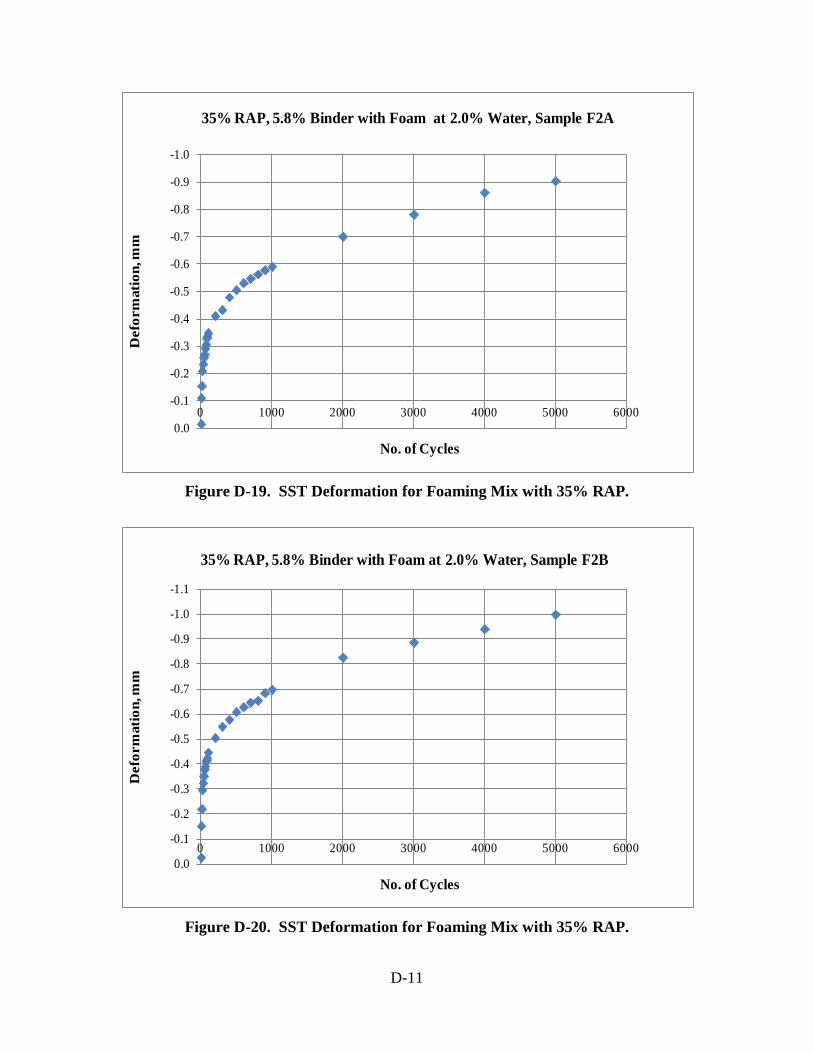
D-11
Figure D-19. SST Deformation for Foaming Mix with 35% RAP.
Figure D-20. SST Deformation for Foaming Mix with 35% RAP.
-1.0
-0.9
-0.8
-0.7
-0.6
-0.5
-0.4
-0.3
-0.2
-0.1
0.00 1000 2000 3000 4000 5000 6000
Def
orm
atio
n, m
m
No. of Cycles
35% RAP, 5.8% Binder with Foam at 2.0% Water, Sample F2A
-1.1
-1.0
-0.9
-0.8
-0.7
-0.6
-0.5
-0.4
-0.3
-0.2
-0.1
0.00 1000 2000 3000 4000 5000 6000
Def
orm
atio
n, m
m
No. of Cycles
35% RAP, 5.8% Binder with Foam at 2.0% Water, Sample F2B
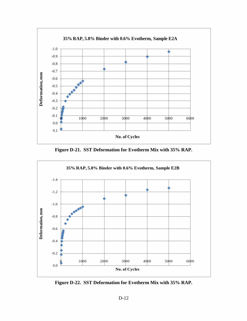
D-12
Figure D-21. SST Deformation for Evotherm Mix with 35% RAP.
Figure D-22. SST Deformation for Evotherm Mix with 35% RAP.
-1.0
-0.9
-0.8
-0.7
-0.6
-0.5
-0.4
-0.3
-0.2
-0.1
0.0
0.1
0 1000 2000 3000 4000 5000 6000
Def
orm
atio
n, m
m
No. of Cycles
35% RAP, 5.8% Binder with 0.6% Evotherm, Sample E2A
-1.4
-1.2
-1.0
-0.8
-0.6
-0.4
-0.2
0.00 1000 2000 3000 4000 5000 6000
Def
orm
atio
n, m
m
No. of Cycles
35% RAP, 5.8% Binder with 0.6% Evotherm, Sample E2B

D-13
Figure D-23. SST Deformation for HMA with 35% RAP.
Figure D-24. SST Deformation for HMA with 35% RAP.
-1.2
-1.1
-1.0
-0.9
-0.8
-0.7
-0.6
-0.5
-0.4
-0.3
-0.2
-0.1
0.00 1000 2000 3000 4000 5000 6000
Def
orm
atio
n, m
m
No. of Cycles
35% RAP, HMA with 5.8% Binder, Sample H2A
-0.8
-0.7
-0.6
-0.5
-0.4
-0.3
-0.2
-0.1
0.0
0.1
0 1000 2000 3000 4000 5000 6000
Def
orm
atio
n, m
m
No. of Cycles
35% RAP, HMA with 5.8% Binder, Sample H2B

D-14
Table D-1. Air Voids of SST Samples.
% RAP Sample IDAir Voids,
%
S1A 7.5S1B 6.2F1A 6.9F1B 6.8E1A 7.8E1B 7.0H1A 7.7H1B 6.9S3A 6.2S3B 7.0F3A 6.6F3B 6.7E3A 6.8E3B 6.3H3A 6.5H3B 6.6S2A 7.8S2B 6.9F2A 7.0F2B 7.8E2A 7.5E2B 7.4H2A 7.6H2B 7.1
0%
15%
35%

E-1
Appendix E
DRAFT GUIDELINES FOR USAGE OF WARM-MIX ASPHALT WITH HIGH PERCENT RAP (HIGH-RAP WMA)
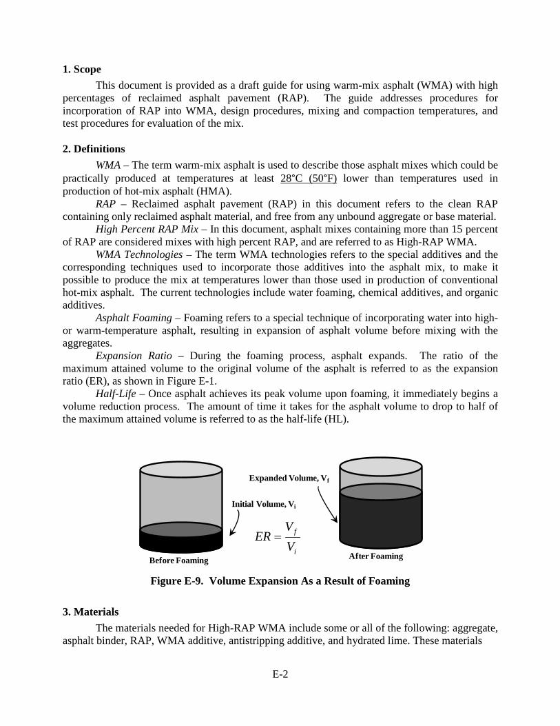
E-2
1. Scope This document is provided as a draft guide for using warm-mix asphalt (WMA) with high
percentages of reclaimed asphalt pavement (RAP). The guide addresses procedures for incorporation of RAP into WMA, design procedures, mixing and compaction temperatures, and test procedures for evaluation of the mix. 2. Definitions
WMA – The term warm-mix asphalt is used to describe those asphalt mixes which could be practically produced at temperatures at least 28°C (50°F) lower than temperatures used in production of hot-mix asphalt (HMA).
RAP – Reclaimed asphalt pavement (RAP) in this document refers to the clean RAP containing only reclaimed asphalt material, and free from any unbound aggregate or base material.
High Percent RAP Mix – In this document, asphalt mixes containing more than 15 percent of RAP are considered mixes with high percent RAP, and are referred to as High-RAP WMA.
WMA Technologies – The term WMA technologies refers to the special additives and the corresponding techniques used to incorporate those additives into the asphalt mix, to make it possible to produce the mix at temperatures lower than those used in production of conventional hot-mix asphalt. The current technologies include water foaming, chemical additives, and organic additives.
Asphalt Foaming – Foaming refers to a special technique of incorporating water into high- or warm-temperature asphalt, resulting in expansion of asphalt volume before mixing with the aggregates.
Expansion Ratio – During the foaming process, asphalt expands. The ratio of the maximum attained volume to the original volume of the asphalt is referred to as the expansion ratio (ER), as shown in Figure E-1.
Half-Life – Once asphalt achieves its peak volume upon foaming, it immediately begins a volume reduction process. The amount of time it takes for the asphalt volume to drop to half of the maximum attained volume is referred to as the half-life (HL).
Figure E-9. Volume Expansion As a Result of Foaming
3. Materials
The materials needed for High-RAP WMA include some or all of the following: aggregate, asphalt binder, RAP, WMA additive, antistripping additive, and hydrated lime. These materials
Before Foaming After Foaming
Initial Volume, Vi
Expanded Volume, Vf
i
f
VV
ER =

E-3
must satisfy PennDOT specifications. A sufficient amount of each material must be procured for laboratory mix design and evaluation. 4. Referenced Documents ASTM D5404 PTM 702 AASHTO R35 AASHTO T195 AASHTO TP79 AASHTO T320 AASHTO T283 5. Characterization of Materials
All required materials must satisfy pertinent PennDOT specifications. The RAP must be characterized for both aggregate and asphalt. It is important that the RAP material used in laboratory evaluation be sampled from the final processed RAP that will enter blending with the aggregate in the plant. The RAP aggregate, obtained from Pennsylvania Test Method (PTM) 702, or any other PennDOT-approved procedure, must satisfy required consensus properties. The binder must be recovered according to ASTM D5404 and tested at multiple temperatures using dynamic shear rheometer and bending beam rheometer, to determine its performance grade and critical cracking temperature. The procedure explained in Appendix H of PennDOT Publication 27 (Bulletin 27) must be followed to characterize the RAP material and determine the grade of the virgin binder required. 6. Selection of the WMA Technology
The selected WMA technology must be from the PennDOT approved list. Selection of the appropriate technology depends on cost, availability of the additive, and compatibility of the asphalt production plant with the selected technology. 7. Application Rates for Binder Additives
The application rate for the WMA additive must follow the manufacturer’s recommendations. For foaming, the following guidelines may be followed in case manufacturer’s recommendations are not available or if supplementary information is needed.
Water Application Rates for Foaming – For foaming applications, expansion ratio and half-life should be determined at four different levels of injected water. In general, higher ER and higher HL are both believed to help with better aggregate coating. Higher expansion results in less viscosity and more fluidity, and allows more mix workability. Higher half-life allows more time for the mixing and coating at reduced viscosity and increased workability. In general, for a specific asphalt at a specific water injection temperature, a higher level of water injection results in higher expansion and lower half life. Typically, water level is determined at the intersection of the corresponding curves, as shown in Figure E-2.

E-4
Figure E-2. Optimizing the Foaming Water Content
The expansion of asphalt is not only dependent on the magnitude of injected water, but also on the type of binder (binder chemical characteristics), grade of binder (binder stiffness), and the temperature of binder at the time of injection. Higher temperature is expected to result in higher expansion. However, for WMA, the upper limit of such temperature is limited. Furthermore, at the same temperature and water injection level, various binders behave very differently in terms of expansion. For some binders, considerable expansion could occur, while for others little expansion might be observed. Laboratory testing must be conducted for each unique asphalt to determine its expansion properties. 8. Blending Procedure
The blending procedure for the WMA additive and for incorporation of the additive into the binder must follow the manufacturer’s recommendations. The following guidelines may be followed in case manufacturer’s recommendations are not available or if supplementary information is needed.
Steps for the Foaming Process 1. Binder must be heated in an oven at a temperature of approximately 135 °C (275 °F).
Duration of heating must be sufficiently long to make the binder fluid enough for pouring. 2. While the binder is being heated, start the foaming equipment, and set the reservoir and
exit temperatures at the desired temperature, for example, 138 °C (280 °F) and 141 °C (285 °F), respectively.
3. Some types of foaming equipment may require a reservoir bag with temperature control. For those foamers, the bag must be inserted into the foamer container and the temperature control thermocouples of the bag must be attached to the foaming equipment.
4. Attach the air pressure hose to the air regulator and adjust the pressure to the manufacturer’s recommended level.
Foaming Water Content, %
Exp
ansi
on R
atio H
alf-Life (seconds)
Expansion Ratio
Optimum Water Content, %
Half Life

E-5
5. Select the water application rate for foaming in percent (i.e., percent of the binder mass), and set this application rate into the foamer through the control panel.
6. Select the desired amount of foamed binder if the equipment allows selection of the mass (some foamers have a built-in load cell that controls the magnitude of the foamed binder through a closed-loop system based on the desired mass entered into the system).
7. At this point, the heated fluid binder is poured into the plastic bag residing inside the reservoir of the foamer.
8. Sufficient time must be allowed for the temperature of the binder and the reservoir to establish at the target level.
9. Once the temperature of the binder and reservoir has stabilized, the foaming process can begin. In some foamers, the user is prompted through the control panel to start the foaming process once temperatures are stabilized. These systems do not allow foaming to start unless the target temperature has been reached.
10. Once foaming begins, a hot container is used to collect the foamed asphalt. 11. Use the foamed asphalt immediately with the batched material to prepare the asphalt mix.
Steps to Blend the Evotherm™ into the Virgin Binder
1. Select the size of the can and the binder for blending in a way that, to the extent possible, the final blended material could be consumed once, without the need for reheating at a later time for use.
2. Determine the mass of binder accurately. 3. Use the binder mass to determine the mass of the additive to be blended resulting in the
target rate. 4. Place the binder cans into an oven at 135 ˚C for 45 minutes, until the binder is fluid enough
for pouring. 5. The hot binder can is quickly placed on a scale and the Evotherm™ additive is added to
deliver the established application rate. 6. Immediately after the addition of the additive, the can is placed on a ceramic hot plate with
temperature control. The temperature is set at a level high enough to maintain the binder fluid during blending.
7. A shear blender is applied to stir the additive and asphalt. The blender is gradually lowered into the hot binder and shear blending is conducted for at least 30 minutes, or until the material appears homogenous and uniform. Blending is conducted at an intermediate level such as 500 revolutions per minute (RPM). In general, a low-shear mechanical stirrer will be sufficient for blending as long as it is equipped with appropriate impellers and is capable of blending the additive into the binder homogeneously.
8. The preceding steps are repeated for all application rates using different binder cans. 9. The cans are then labeled corresponding to the percent additive applied.
Steps to Blend the Sasobit™ into the Virgin Binder
1. Select the size of the can and the binder for blending in a way that, to the extent possible, the final blended material could be consumed once, without the need for reheating at a later time for use.
2. Determine the mass of binder accurately. 3. Use the binder mass to determine the mass of the additive to be blended resulting in the
target rate.

E-6
4. Place the binder cans into an oven at 135 ˚C for 45 minutes, until the binder is fluid enough for pouring.
5. During the time the binder is being heated in the oven, small tins are used to weigh out the necessary amount of Sasobit™ for each can.
6. Immediately after the addition of the additive, the can is placed on a ceramic hot plate with temperature control. The temperature is set at a level high enough to maintain the binder fluid during blending.
7. The blender is lowered into the hot binder and set to 1,000 revolutions per minute (RPM), and then the Sasobit™ is slowly added. The binder and Sasobit™ blending continues until all of the Sasobit™ pellets are completely melted. Complete melting is typically observed after approximately 30 minutes from the beginning of the blending process.
8. The preceding steps are repeated for all Sasobit™ application rates using different binder cans.
9. The cans are then labeled corresponding to the percent additive applied.
In general, it appears that higher RAP content will require higher amounts of the additives. Application rates presented in Table E-1 are provided as guidelines.
Table E-1. Additive Application Rates, Mixing and Compaction Temperatures (for PG 64-22 Binder)
Technology % RAP Additive Application Rate, %
Mixing Temperature, °C (°F)
Compaction Temperature, °C (°F)
Evotherm™ 0 0.4 132 (270) 121 (250) Sasobit™ 0 1.5 132 (270) 121 (250) Foaming 0 2.0 138 (280) 128 (262) HMA 0 0.0 147 (297) 138 (280) Evotherm™ 15 0.5 132 (270) 121 (250) Sasobit™ 15 1.75 132 (270) 121 (250) Foaming 15 2.0 138 (280) 128 (262) HMA 15 0.0 147 (297) 138 (280) Evotherm™ 35 0.6 132 (270) 121 (250) Sasobit™ 35 2.0 132 (270) 121 (250) Foaming 35 2.0 138 (280) 128 (262) HMA 35 0.0 147 (297) 138 (280)
It must be noted that the application rates provided in Table E-1 are based on the total binder in the mix (i.e., the summation of the virgin binder and the binder of the RAP). Since the WMA additive is pre-blended with the virgin binder, the rates given in Table E-1 must be adjusted to provide the application rate based on the mass of virgin binder only.

E-7
r(based on virgin binder) = r(based on total binder) * (percent total binder/percent virgin binder) where r = application rate of the WMA additive. It should be noted that these application rates were used with a virgin PG 64-22 asphalt, and at the RAP percentages presented in Table E-1. Stiffer binders and/or higher RAP contents would require higher application rates to maintain mixing temperatures within the range of those considered for WMA. 8. Mixing and Compaction Temperatures
In general, mixing and compaction temperatures depend on the WMA technology incorporated. When a high amount of RAP is blended with virgin material, workability is of concern and temperatures must be sufficiently high to provide enough mix workability. NCHRP Report 452 recommends that the RAP be heated to 110 °C (230 °F) for no more than 2 hours before blending with the virgin material. The report discourages against higher temperatures and longer heating times because of the risk of altering RAP properties. In the proposed appendix of AASHTO R 35 on WMA, which is based on the results of NCHRP 9-43 research, it is recommended that the RAP be heated in the oven with the aggregates at approximately 15 °C higher than the mixing temperature, but that the heating time for the RAP should be limited to 2 hours.
Mixing and compaction temperatures presented in Table E-1, utilized at Penn State’s Pavement Materials Research Laboratories, provided acceptable coating and compaction of produced mixes. It should be noted that these temperatures were used with a virgin PG 64-22 asphalt, at the RAP percentages presented in Table E-1. Stiffer binders and/or higher RAP contents would require higher temperatures to maintain the mix workability at acceptable levels. However, a change in application rate of the WMA additive may be needed to maintain satisfactory levels of mixing and compaction, if temperatures cannot exceed the established limits. NCHRP 9-43 recommends that for WMA-RAP, the compaction temperature be greater than the as-recovered high temperature grade of the RAP binder. For example, if the RAP binder is graded as a PG 92, the compaction temperature should not drop below 92 °C (approximately 200 °F). 9. Laboratory Blending Procedure
Once materials have been conditioned for the proper duration at specified temperatures, RAP and virgin aggregate are first blended, followed by addition of the virgin binder. For foaming applications, the transport of the foamed binder to the batched material should take place as quickly as possible so that the expanded volume of foamed binder helps with more effective coating during the mixing process. 10. Mix Design
It is currently recommended that the mix design be carried out according to PennDOT Bulletin 27 as established for HMA with high RAP. The optimum binder content determined based on HMA mix design will be utilized in production of WMA with high RAP. In cases where differences exist between the procedure outlined in Bulletin 27 and what follows in this document, the procedures stated in this document prevail.

E-8
Air Void Considerations: The air void content of the WMA at the optimum binder content designed based on HMA should be checked through preparation of three laboratory Superpave gyratory compacted specimens at design number of gyrations. If the average air voids of the three specimens exceeds ±1 of the HMA design air voids, adjustments to binder content are needed to bring the air voids within ±1 of the HMA design air voids.
Evaluation parameters: The following evaluations are recommended for the WMA-RAP, as outlined in the proposed draft appendix of AASHTO R 35 on WMA.
• Coating • Compactibility • Rutting Resistance • Moisture Damage Resistance
Coating Evaluation: The coating evaluation follows AASHTO T195 and is recommended
in lieu of viscosity-based mixing temperature. It ensures that the applied mixing temperature is sufficiently high to provide full coating of the aggregates.
Compactibility Evaluation: The compactibility evaluation is performed to ensure that the mix is workable and compactible at the applied compaction temperature. The procedure is explained in the proposed draft appendix of AASHTO R 35 on WMA. Gyratory specimens are prepared at the design number of gyrations at the proposed compaction temperature and at a temperature 30 °C (54 °F) below the proposed compaction temperature. At each of these two compaction temperatures, the number of gyrations to achieve 92 percent density is determined. The ratio of number of gyrations at the lower compaction temperature to the number of gyrations at the proposed compaction temperature is referred to as the compactibility gyration ratio (GR) and should be less than 1.25.
25.1)(
)(
%92
30%92 ≤= −
T
T
NNGR
Rutting Evaluation: It is recommended that the rutting resistance be evaluated using a
PennDOT-approved procedure. Based on NCHRP 9-43, the AASHTO TP79, Determining the Dynamic Modulus and Flow Number of Hot-Mix Asphalt Using the Asphalt Mixture Performance Tester (AMPT), is recommended by the proposed draft appendix of AASHTO R 35 on WMA. For the PennDOT-sponsored research project on WMA-RAP (WO-32), two different types of tests were conducted to evaluate rutting resistance: accelerated pavement testing using the Model Mobile Load Simulator, Third Scale (MMLS3), and AASHTO T320, Standard Method of Test for Determining the Permanent Shear Strain and Stiffness of Asphalt Mixtures using the Superpave Shear Tester (SST). Both of the tests utilized under project WO-32 are capable of providing valuable data in determining the rutting susceptibility of the mix.
Evaluation of Moisture Damage Resistance: The moisture damage resistance is evaluated according to the modified version of AASHTO T283, as detailed in Bulletin 27.

E-9
Evaluation of Fatigue Resistance: Project WO-32 did not address the mix fatigue resistance. Nor does the proposed draft appendix of AASHTO R 35 on WMA cover how fatigue performance of WMA should be evaluated. In general, it is believed that mixes with higher RAP content are more prone to fatigue damage. However, fatigue resistance might be enhanced through the use of WMA additives, and hence counteracting the effect of higher RAP content. Further research is needed to address this important issue.