development of dual clutch transmission for vfr1200f
TRANSCRIPT

Development of Dual Clutch Transmission for VFR1200F
− 9 −
Development of Dual Clutch Transmission for VFR1200F
Masataka TANAKA* Dai ARAI* Junya WATANABE*
Kazuyuki FUKAYA* Eiji KITTAKA* Masahiko TSUCHIYA*
ABSTRACT
The dual clutch transmission (DCT) for motorcycles that provides direct response to throttle operations without interruption of traction at shift was developed and installed on the VFR1200F.
This system has two separate hydraulic circuits for two clutches to provide individual controls. Weak creep control at departure, deceleration adaptive shift-down control, predictive cornering shift control, and other controls were developed to achieve the advanced performances in the vehicle departure and the shift change characteristic that are demanded for motorcycles. With those performances, riders can enjoy the pleasures of riding without depending on rider’s skills. Compact design of this DCT system has made it possible to share the same crankcase raw casting materials with manual transmission (MT) type which is developed in parallel, and this design has enabled the installation on the common frame with MT system.
1. Introduction
There are two types of mechanism commonly used for the automatic transmission for large motorcycles. One is the belt converter type for scooters, and the other is HFT (Human Friendly Transmission)(1) which is applied to Honda DN-01. These are both categorized in Continuously Variable Transmission (CVT), and they provide smooth gear shifting for enjoyable driving performance. On the other hand, there are people who like conventional manually operated multi-step transmissions seeking the sporty feeling with linear and direct responses of the driving force to the throttle operation, which is one of the requirements for sports motorcycles. Having these two opposing requirements in consideration and pursuing the value of this new automatic transmission motorcycle which is not dependent on rider’s skills, the world’s first DCT(2) system for motorcycles has been developed and installed on the VFR1200F. The present paper will describe the main technical points of this development.
2. Overview of VFR1200F
VFR1200F (Fig. 1) was developed with the aim of creating a large sports-tourer motorcycle that achieves high-level integration of advanced technologies and its original styling.
The engine (Fig. 2) adopts “UNICAM”(3) that actuates both intake and exhaust valves with a single camshaft, making its cylinder head compact to concentrate the engine
* Motorcycle R&D Center
Fig. 1 VFR1200F with dual clutch transmission
Fig. 2 External view of V4 engine with newly developed dual clutch transmission
Introduction of new technologies
Honda R&D Technical Review April 2011
− 10 −
mass and realizing a lower center of gravity. The engine is V-type and has a cylinder bank angle of 76 degrees combined with a 28-degree phase pin crankshaft so that primary vibration is counterbalanced without any balance shaft. It provides powerful and flat torque in low-speed range while realizing smooth throttle response in high-speed range, together with the unique pulse feeling and exhaust sound of V4-engines.
The throttle-by-wire (hereafter TBW) system, which controls the throttle valve electrically, and the electronically controlled fuel injector (hereafter PGM-FI) enable good engine responses that reflect the rider’s intentions.
Pro-Arm type is applied to the swing arm. The pivot and the propeller shaft are placed in an offset position. Variations in shaft length that arise from vertical movements of the suspension can be compensated by a constant-velocity joint located on the propeller shaft. This structure achieves both ride comfort and the driving stability as a sports-tourer.
Adoption of the DCT makes riders free from clutch operations that may be annoying when driving on city streets while allowing them to enjoy sport riding easily on winding roads.
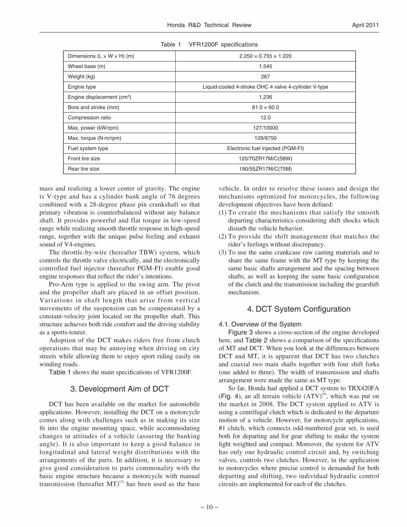
Table 1 shows the main specifications of VFR1200F.
3. Development Aim of DCT
DCT has been available on the market for automobile applications. However, installing the DCT on a motorcycle comes along with challenges such as in making its size fit into the engine mounting space, while accommodating changes in attitudes of a vehicle (assuring the banking angle). It is also important to keep a good balance in longitudinal and lateral weight distributions with the arrangements of the parts. In addition, it is necessary to give good consideration to parts commonality with the basic engine structure because a motorcycle with manual transmission (hereafter MT)(3) has been used as the base
Dimensions (L × W × H) (m) 2.250 × 0.755 × 1.220
1.545
267
Liquid-cooled 4-stroke OHC 4 valve 4-cylinder V-type
1,236
81.0 × 60.0
12.0
127/10000
129/8750
Electronic fuel injected (PGM-FI)
120/70ZR17M/C(58W)
190/55ZR17M/C(75M)
Wheel base (m)
Weight (kg)
Engine type
Engine displacement (cm3)
Bore and stroke (mm)
Compression ratio
Max, power (kW/rpm)
Max, torque (N·m/rpm)
Fuel system type
Front tire size
Rear tire size
vehicle. In order to resolve these issues and design the mechanisms optimized for motorcycles, the following development objectives have been defined:(1) To create the mechanisms that satisfy the smooth
departing characteristics considering shift shocks which disturb the vehicle behavior.
(2) To provide the shift management that matches the rider’s feelings without discrepancy.
(3) To use the same crankcase raw casting materials and to share the same frame with the MT type by keeping the same basic shafts arrangement and the spacing between shafts, as well as keeping the same basic configuration of the clutch and the transmission including the gearshift mechanism.
4. DCT System Configuration
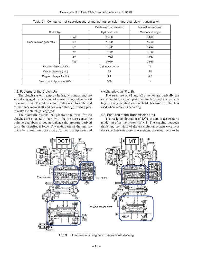
4.1. Overview of the SystemFigure 3 shows a cross-section of the engine developed
here, and Table 2 shows a comparison of the specifications of MT and DCT. When you look at the differences between DCT and MT, it is apparent that DCT has two clutches and coaxial two main shafts together with four shift forks (one added to three). The width of transmission and shafts arrangement were made the same as MT type.
So far, Honda had applied a DCT system to TRX420FA (Fig. 4), an all terrain vehicle (ATV)(4), which was put on the market in 2008. The DCT system applied to ATV is using a centrifugal clutch which is dedicated to the departure motion of a vehicle. However, for motorcycle applications, #1 clutch, which connects odd-numbered gear set, is used both for departing and for gear shifting to make the system light weighted and compact. Moreover, the system for ATV has only one hydraulic control circuit and, by switching valves, controls two clutches. However, in the application to motorcycles where precise control is demanded for both departing and shifting, two individual hydraulic control circuits are implemented for each of the clutches.
Table 1 VFR1200F specifications
Development of Dual Clutch Transmission for VFR1200F
− 11 −
4.2. Features of the Clutch UnitThe clutch systems employ hydraulic control and are
kept disengaged by the action of return springs when the oil pressure is zero. The oil pressure is introduced from the end of the inner main shaft and conveyed through feeding pipe to make the clutch get engaged.
The hydraulic pistons that generate the thrust for the clutches are situated in pairs with the pressure canceling volume chambers to counterbalance the pressure derived from the centrifugal force. The main parts of the unit are made by aluminum die casting for heat dissipation and
weight reduction (Fig. 5).The structure of #1 and #2 clutches are basically the
same but thicker clutch plates are implemented to cope with larger heat generation on clutch #1, because this clutch is used when vehicle is departing.
4.3. Features of the Transmission UnitThe basic configuration of DCT system is designed by
modeling after the system of MT. The spacing between shafts and the width of the transmission system were kept the same between those two systems, allowing them to be
DCT MT
Dual clutch
Gearshift mechanism
Transmission
Dual clutch transmission Manual transmission
900
4.9
75
2 (Inner + outer)
0.939
1.032
1.160
1.409
1.789
2.466
Hydraulic dual
-
4.0
75
1
0.939
1.032
1.160
1.363
1.736
2.600
Mechanical singleClutch type
Low
2ndTrans-mission gear ratio
3rd
4th
5th
Top
Number of main shafts
Center distance (mm)
Engine oil capacity (lit.)
Clutch control pressure (kPa)
Fig. 3 Comparison of engine cross-sectional drawing
Table 2 Comparison of specifications of manual transmission and dual clutch transmission

Honda R&D Technical Review April 2011
− 12 −
manufactured from the same raw casting materials. Inner main shaft and odd-numbered gears, such as first gear, third gear and fifth gear, are connected to #1 clutch while outer main shaft and even-numbered gears, such as second gear, fourth gear and sixth gear, are connected to #2 clutch (Fig. 6). It also adopts the same scheme of dog shifting as MT system in which gears themselves are moved along the shaft to establish direct coupling.
In the DCT system, so called pre-shifting is necessary where the next expected gear is connected in advance to get ready for the following shifting by switching of oil pressure to create the actual transitions of driving force. However, in the dog clutch type transmission systems, not like in the
Clutch pistonsClutch plates
Canceller volume
#1 clutch oil line(Odd-numbered gears)
#2 clutch oil line(Even-numbered gears)
Piston volume
Friction disks
Fig. 4 TRX420FA
Fig. 5 Structure of dual clutch
case of the systems for four-wheeled vehicles equipped with synchronizing mechanisms, the impact noises are generated associated with the abrupt changes in revolutions of gears and shafts when they are engaged for pre-shifting. Even though the same impacting noise is observed in MT systems as well, it is important for DCT systems to take care of the reduction of the noise because this noise, when it’s compared to MT systems, is more likely to be annoying as this noise generation, in this particular case, has no correspondences to the rider’s operations. Accordingly, gear ratios, from first speed to third speed, have been changed from those of the MT system (Table 2) and the drive train damper dedicated to the DCT system is implemented and the noise transfer paths are optimized as the noise reduction measures. These measures contribute to the reduction of the shock as well.
4.4. Features of the Shift MechanismBased on the design for MT type, the shift mechanism
is structured by changing means of operation for the shift spindles from a foot-manipulated shift pedal to the controlled electric motor with reduction gear train. The shift drum has twelve positions suited for neutral position, first speed position through sixth speed position and the positions in between that are to make both gears engaged for the adjacent positions to prepare for the shift transitions (Table 3).
In this system, gears out of driving force stands still in neutral position in order to keep the same response time for both shift-up and shift-down and to get good fuel economy by reducing the frictional losses in the non-driving clutch.
4.5. Features of the Hydraulic CircuitsThe oil pressure for controlling of clutch piston thrust,
which is generated by the oil pump specifically designed for DCT system, is branched into two paths and controlled by linear solenoid valves in the individual hydraulic circuits of the two clutches. Each circuit has its own oil pressure sensor to cope with the variations of engine oil, which works as operational fluid for hydraulic circuits. Those
Reduction gearsGearshift spindle
To angle sensor
Shift drum
#1 clutch
Outershaft for 3rd, 5th, 1st gearsInnershaft for2nd, 6th, 4th gears
Mainshaft
Countershaft
Shift forks
To angle sensor
Control motor
#2 clutch
Engaged gear
Shift drumposition #
Gearshiftconditions
Odd-numbered
gears
Even-numbered
gears
123456789101112
N11N333N555N
NN222N444N66
NeutralStart, 1st1st⇔2nd shift2nd2nd⇔3rd shift3rd3rd⇔4th shift4th4th⇔5th shift5th5th⇔6th shift6th
Fig. 6 Transmission and gearshift mechanism
Table 3 Shift drum position and gearshift conditions

Development of Dual Clutch Transmission for VFR1200F
− 13 −
#2 linear solenoid valve
#2 clutch EOPsensor
Inner coverpipe #1 clutch EOP
sensor
#1 linear solenoid valve
Clutch lineEOP sensor
Clutch oilfilter pipe
Pressurerelief valve
Clutch filter
Oil pump(Clutch feed pump)
Engine lubrication oil lineDCT oil line
Fig. 7 Hydraulic circuits
Main shaft(Dual clutch) Oil line
Hydraulic componentsconcentrated on right-side
cover of engine
#1 linearsolenoid valve(1st-3rd-5th/start)
#2 linearsolenoid valve(2nd-4th-6th)
Engineright-sidecover Oil filter
(for DCT)
Fig. 8 Engine right-side cover layout
oil variations are the differences in kinds of oil and the changes in oil viscosity that depends on its temperature. By arranging those hydraulic circuits all within the right-hand engine covering, it has been made possible to share the same crankcase with MT type (Figs. 7 and 8).
speeds of each shafts, angel of shifting mechanism, oil temperature, clutch oil pressure, and so on, are monitored to calculate the targeting position referring to the shifting map followed by outputting signals that control the clutch oil pressure and the shift mechanism.
5.2. Measures Taken for Engine Oil VariationsMotorcycles ordinar i ly share the same oi l for
transmission lubrication and for the engine oil. This feature has also been applied to this system and the engine oil is used for hydraulic fluid and for lubricant as well. However, engine oil generally experiences greater changes in viscosity due to temperature variations when it’s compared to automatic transmission fluid (hereafter ATF), making it necessary to have measures to deal with the changes in viscosity in flexible manner.
Therefore, this system adopts hydraulic feedback control system using oil pressure sensor, which continuously monitors oil pressure to clutches, and the function that estimates viscosity of the oil through characteristics of the oil pressure responses has been incorporated as well. The system is configured to provide a flexible response to oil temperature and viscosity changes by switching feedback gain based on the estimated oil viscosity. This minimized the influence of viscosity changes on the feeling of departing operations and the gear shifting operations, enhancing the responses of the hydraulic control system as well.
5.3. Control of DepartureSince the motorcycle rider must hold the vehicle steady
using his or her foots when stopping, the system has to restrain the generation of creep-torque by disengaging the clutch when the motorcycle is in gear and stopped with throttle closed. However, it becomes challenging to make precise control of the torque transfer on the clutch if the hydraulically controlled departure clutch is under the control of without creep torque, because it is necessary to move the clutch piston with a large amount within a short period of time just after the departing operation is applied.
In order to resolve this issue, this system employs the weak creep control. Making use of the time lag in engine responses, this control method is devised to make the transition of the clutch piston complete within the time between the beginning of throttle opening to the point that the engine revolution goes up. First, when opening of the throttle is detected, the target pressure for the hydraulic clutch control is raised to the state where weak creep occurs. Since the throttle is already open at this time, there is no issue in terms of usability, even if the vehicle moves forward in a creep state. When there is the response of engine output followed by the increased engine speed, the target transfer torque is applied to the clutch in accordance with the throttle opening and the engine speed (Fig. 10). Applying this control sequence, smooth departure performance has been realized by providing the clutch
5. DCT Control
5.1. Overview of Control SystemFigure 9 illustrates the configuration of input signals to
the electronic control unit (hereafter ECU), such as signals from switches and sensors, and output signals from ECU. The rider’s intentions, detected through throttle opening and operations of switches, the status of the engine speed, the status of the vehicle traveling, through vehicle speed, and the state of operation of DCT system, through revolution

Honda R&D Technical Review April 2011
− 14 −
Fig. 10 Time chart during starting
status just ready to transfer the torque before engine speed goes up while ensuring disengagement of the clutch before departure.
5.4. Shift OperationDCT shift operation occurs in the following order:
(1) When a shift command is applied, the system makes the gear, which is to be activated in the following shift stage, engaged, establishing the status with both gears
engaged for one odd-numbered gear and one even-numbered gear (pre-shift).
(2) By switching the clutch hydraulic pressure the engaging clutch is to be disengaged, and vice versa.
(3) The drop in oil pressure in the clutch of non-driving side is detected by the sensor, and by disengaging the dogs on the non-driving side it is placed in neutral standing-by state. This completes the gear shifting.The gearshift mechanism applied to this motorcycle is
of the dog clutch type and, using this mechanism for the DCT shifting means, it gets the advantage of short pre-shift time compared to the synchromesh type mechanism generally used in four-wheel vehicles. Accordingly, in this system, the time lag before completion of pre-shift is about 70 ms which achieves the good performance in gearshift responses.
However, because of the structural nature of the mechanism, it is impossible to perform a jump-shift, where the system shifts the gears between two or more speeds at a time. Therefore, the time needed for shifting has been made short by constantly monitoring the outputs from the sensors and by coupling the gear shifting control with the hydraulic pressure control.
By making the operation time as short as possible through coordination of mechanical functions, it has achieved the interval of 500 ms or less between successive receptions of requests for gearshift (Fig. 11).
In MT systems, the interruption of the driving force is needed for gear-shifting by operations of clutch and throttle. On the other hand, in this DCT system, it has been made possible to make gear-shift without interruption of the
Engine speed
Throttle angle
#1 clutch piston stroke
Increase in engine speedThrottle open
(1) No creep
(2) Weak creep
(3) Clutch slipping
(4) Fully engaged
Vehicle speed
Hyd
raul
ic g
ener
ated
wea
k cr
eep
torq
ue
Transmissionspeed
ABS modulator
Sidestand
PCM
[1] AT/MT MODE SIGNAL[2] N-D SHIFT SIGNAL[3] FRONT WHEEL SPEED SIGNAL[4] REAR WHEEL SPEED SIGNAL[5] FRONT BRAKE LIGHT SWITCH SIGNAL[6] SHIFT DOWN SIGNAL[7] SHIFT UP SIGNAL[8] SIDESTAND SWITCH SIGNAL[9] TBW MOTOR OUTPUT[10] TBW TP SENSOR SIGNAL[11] AP SENSOR SIGNAL[12] CKP SENSOR SIGNAL[13] #1 CLUTCH OIL PRESSURE SIGNAL[14] #1 LINEAR SOLENOID OUTPUT[15] #2 LINEAR SOLENOID OUTPUT[16] CLUTCH OIL PRESSURE[17] OIL TEMPERATURE SIGNAL[18] #2 CLUTCH OIL PRESSURE SIGNAL[19] SHIFT SPINDLE ANGLE SIGNAL[20] OUTER MAINSHAFT REVOLUTION SIGNAL[21] SHIFT CONTROL MOTOR OUTPUT[22] SHIFT DRUM ANGLE SENSOR SIGNAL[23] INNER MAINSHAFT REVOLUTION SIGNAL[24] SERIAL COMMUNICATION
[24]
[1][2][3][4][5][6][7][8][9]
[10][11][12]
[13]
[14]
[15]
[16]
[17]
[18][19][20][21][22][23]
Parking brakeswitch
PGM-FIcontrol
DCTcontrol
Fig. 9 Diagram of control system

Development of Dual Clutch Transmission for VFR1200F
− 15 −
traction by switching two clutches in continuous manner. Figure 12 shows a conceptual view of this scheme. Maximizing the advantage of this feature, the system is controlled to get the smooth torque transition to the rear wheel by determining the optimum clutch transfer torque through the estimated values of engine torque and the differences between gear ratios before and after shifting. This enables to maintain the uninterrupted acceleration and to reduce the vehicle pitching at gearshifts.
5.5. Features of Shift Timing ControlShift timing is basically determined by base shift-tables
for individual driving modes referring vehicle speeds and throttle opening signals. As the driving modes, it has three modes, D mode, S mode and MT mode. D mode is designed by assuming city driving with consciousness of fuel economy. S mode is designed for driving with relatively high engine speed aiming at sport riding on winding roads. MT mode provides the rider’s choice of gear positions that are changed by UP/DOWN switch on the left steering grip (Fig. 13).
In order to realize the performances of sport riding expected for motorcycles with an AT system as well, it is important for the system to select appropriate gears during the entire stretch of corner driving from the approaching at the entrance of a corner to the exit of the corner. Keeping that in mind, several controls have been added based on the analysis of gear shifting patterns of expert riders. These controls are described below.
Fig. 11 Time chart of gearshift sequence
Fig. 12 Comparison between MT motorcycle and DCT motorcycle using time chart of gearshift
Operation
Comfort
Sportsriding MT
Easy
DCT
MT modeSelecting gearvia shift switch
AT: D modeBetter fueleconomy
AT: S modeSports riding
S mode
D mode
MT mode
Fig. 13 Gearshift modes
Output of gearshiftspindle angle sensor
Targetgear position
#1 clutch oil pressure(Odd-numbered gear)
#2 clutch oil pressure(Even-numbered gear)
Start of preliminarygearshift
End of preliminarygearshift
Release of disengaged clutch
500 ms Max.
Engine speed
Shift drum position
End of gearshift
1-21-N
N-2
Time
Time
Time
MTDCT
Rear wheel traction
Rear wheel traction
Rear wheel traction
Vehicle speed
Engine speed
Throttle opening angle
Vehicle speed
Engine speed
Throttle opening angle
MT motorcycle
DCT motorcycle
MT and DCT
Vehicle speed
5.5.1. Deceleration adaptive shift-down controlIt is important for sport riding to keep the stability of the
vehicle with engine braking when it is heading into a corner by applying shift downs, and it also contributes to make a good preparation to get sufficient acceleration when getting out of a corner. To cope with this requirement, the system employs the control logic which makes early shift downs in accordance with the deceleration of the vehicle to realize a gearshift pattern similar to that of manual operations by real riders (Fig. 14).

Honda R&D Technical Review April 2011
− 16 −
Fig. 15 Cornering detection logic
Fig. 16 Comparison of blipping effect
Throttle
Vehicle speed
Acceleration
CorneringDetectionFlag
Suppressed gearshiftduring cornering
ON
Open
Close
OFF
+–
Inner mainshaft speed
Rotation synchronized
Throttle angle Throttle angle
Vehicle speed Vehicle speed
500 ms Target gearsposition
170 ms Time
Engine speedEngine speed
#2 clutch oilpressure
#1 clutch oilpressure
Outer mainshaft speed
Without blipping With blipping
5.5.2. Predictive Cornering Shift ControlIt is one of the features of a motorcycle which is leaned
when driven in a corner. Consequently, frequent occurrence of abrupt gearshifts is highly unfavorable for motorcycles. However, it is challenging in motorcycle systems to get the information whether the vehicle is in cornering state while driving compared with four-wheel vehicles where the detection of cornering status is relatively easy by using, for examples, the steering angle and/or the rotational differences between left and right wheels. To overcome this issue, the quasi cruising status which appears while cornering has been noticed and the driving status has been divided into three stages, acceleration stage, cruising stage and deceleration stage. The logic has been introduced to suppress the sift-ups while cornering, by dynamically changing the shifting schedule when a transition occurs from accelerat ion s tage to cruising stage or from deceleration stage to cruising stage. The adoption of this cornering detection logic enabled effective suppression of shifting operation during cornering without adding sensors or other such devices for bank angle detection (Fig. 15).
5.6. Blip ControlAs rider’s intention involves when the system initiates
6th
5th
4th
3rd
2nd
TimeEffective engine brake
Throttle opening angle
With early shift down logic
Without early shift down logic
Vehicle acceleration
Vehicle speed
Target gear position
Fig. 14 Early shift down logic during deceleration
gearshifts in MT mode, the control design can be put more emphasis on shorter shifting time. So called blip control has been implemented in this system in which, while downshifting, both clutches of odd-numbered and even-numbered are made disengaged during the shift operations and, having the coordination with TBW system, the engine speed is raised to meet the rotation speed of the next gear to be engaged (Fig. 16). With this blip control, the time needed for the completion of a gear shift has been made short from 500 ms to 170 ms compared with AT mode.
This control can provide sport feelings for inexperienced riders as well because riders can enjoy the blipping while shift-down that is usually performed only by expert riders.
5.7. Initial Learning of ClutchThe performance of the clutch engagement in each
individual system varies because of the variation in the clutch engagement points caused by deviations of the

Development of Dual Clutch Transmission for VFR1200F
− 17 −
clutch disk clearance and the clutch return spring load. It is important to calibrate those deviations of individual systems because, in this DCT system for motorcycle, all the controls of clutch engagements are done based on the reference oil pressure level which corresponds to the clutch engagement point, and because highly precise clutch controls with good accuracy is needed in this system. In addition to that, the calibration of the system needs to be done easily in the service field when the clutch system is replaced for maintenance, as well as in the factory for pre-shipment adjustments. Taking those requirements in consideration, the initial learning method for clutches in DCT system has been developed.
The initial learning of clutch involves raising the target hydraulic pressure at the set speed. The clutch engagement point is then estimated from varying behavior of the actual hydraulic pressure and the value of that point is recorded in the ECU. The introduction of this calibration has enabled the uniform engagement performance across the entire tolerance range and contributes to the stable, precise clutch engagement control.
6. Conclusions
A DCT system for motorcycles, which provides direct responses to throttle operations without causing traction interruptions at shifts, was developed and installed on VFR1200F. This realized a motorcycle with new value. The main points of technologies involved are as follows:(1) Realization of smoothness both in vehicle departure
characteristics and shifting operations by the optimized transmission ratios and damper characteristics, the weak creep control, and the control using initial learning of the clutch conditions.
(2) Realization of the shift management without providing any feeling of discrepancy to the riders by predictive cornering shift control, the deceleration adaptive shift-down control and blip control.
(3) Realization of common use of raw casting materials for the crankcase with the MT system and the installation on the same frame as MT’s, by arranging all the DCT hydraulic control circuits within the right-hand engine cover, and by adopting the arrangement of the two clutches in series and the coaxial dual main shafts structure.
References
(1) Yoshida, Y., Yakigaya, N., Nakamura, K., Takeuchi, K., Nakano, K., Usukura, Y.: New Generation Hydraulic-Mechanical Transmission with Lock-up Mechanisms and Automatic Start Clutch, SAE Paper, 2008-32-0040 (2008)
(2) Watanabe, J, Arai, D., Abe, T., Tanaka, M., Ogasawara, A., Tsuchiya, M., Tsubota, R.: Development of Dual Clutch Transmission for Large Motorcycles, SAE Paper,
2010-32-0057 (2010)(3) Kisaichi, T.: Technologies for Enabling Concept of
New-geometry 4-cylinder V-type Engine, SAE Paper, 2009-32-0059 (2009)
(4) Mizuno, K., Hamaoka, S., Kittaka, E., Kobayashi, M.: Development of 5-speed Dual-clutch Transmission System for All-Terrain Vehicle, Honda R&D Technical Review, 2008, October, p. 76-82
Author
Masataka TANAKA Dai ARAI Junya WATANABE
Kazuyuki FUKAYA Eiji KITTAKA Masahiko TSUCHIYA