development of an automated and dedicated measuring system ... · pdf filedevelopment of an...
TRANSCRIPT
DEVELOPMENT OF AN AUTOMATED AND DEDICATED MEASURING
SYSTEM FOR INTERNAL DIAMETER INSPECTION
Benedito Di Giacomo, [email protected]
Rodrigo Juliano Silva, [email protected] School of Engineering of São Carlos – USP – Av. Trabalhador Sãocarlense, 400 – 13566-590
Fabrício Tadeu Paziani, [email protected] Federal University of São Carlos
Abstract. Certain internal cylindrical surfaces require diameter inspection by means of bore gauges due to either
shape-inherent difficulties or poor access to the measuring point. Measurements with such instruments, which call for
skilled operator, are generally long and may present high uncertainty levels when inspecting mid-size or large part
batches. Accurate measurements with low associated uncertainty and cost-effective inspection time are decisive to
quality and productivity improvement, since dimensional information is essential to ensure that parts produced by
several manufacturing processes lie within specifications. This work aims to present the development of an automated
and dedicated diameter measuring system that simulates bore gauge inspection. An industrial robot, which was
employed to manipulate inductive type displacement probes, replaces the human operator. In order to achieve
measurements, a Delphi language object-oriented algorithm was developed to provide communication among
displacement probes, a microcomputer and the robot control system, by means of an AD/DA acquisition board.
Measured values were compared to pertinent metrological standards. The results were consistent and demonstrated
the efficiency of the proposed measuring system, both technically and economically
Keywords: Measurement automation; industrial robot; bore inspection
1. INTRODUCTION
Several industries are concerned about qualifying a product, as competition is getting fiercer and fiercer. Therefore,
qualification processes are becoming more demanding. Consequently, the techniques to enhance measurement
processes are gaining visibility, since knowing the dimensions is essential to ensure that the pieces produced through
several manufacturing processes lie within specifications.
Industrial competition requires the development of automated systems and pursuits productivity and quality
enhancement that promote objectivity and speed up measurement processes, within a metrological dimensional
perspective. For instance, there are industries that produce hundreds of thousands of cylindrical pieces that have simple
geometry, whose diameter must be controlled in terms of micrometers.
The evolution of technology and the development of new measurement systems integrated to manufacturing
process provided some changes. Tasks that were previously carried out by humans may know be performed by
machines (Sakakibara, 2003).
This technology was created in 1954, when coordinate-measurement machines (CMMs) were brought to the
industrial scenario. This way, complex measurements could be obtained. Previously, they were carried out with
conventional instruments in specialized Metrology laboratories. However, using CMMs is not always viable - for
instance, when measurement of serial pieces are done without temperature control (Griffith, 1994).
An automated measuring system may be implemented using an industrial robot equipped with adequate sensors to
perform the measurement. However, the use of industrial robots as measuring systems is not trivial and the low
positioning accuracy consists a serious restriction. Regarding coordinating measurement, the accuracy levels presented
by the industrial robots nowadays do not suffice to present good results.
Kato et al, 1991, presented a measuring system that used a robot with a displacement sensor that was used to
measure circularity error. The robot placed the sensor in three distinct points over the piece and measurement was
carried out at each point. As measurement range was ±2 μm, a piezoelectric actuator placed the displacement within the
range to perform the measurement. When the authors compared the results with the measurement conducted using a
conventional instrument, they found errors in 17% in the 1 μm (10 to 12 lobes) components.
Regarding non-contact measurement, many enterprises have been implementing the use of laser scanning placed at
the edge of the manipulators aiming to carry out the so called more accurate measurements. Nevertheless, the accuracy
has proved to be related to the robot accuracy itself, i.e. about 0.1 mm. Therefore, some precaution should be taken into
consideration when the position of the robot is used as a reference for laser-scanning measurement.
Lee and Park, 2000 designed an algorithm to inspect parts whose measurement was carried out using laser
scanning. Boillot and Uota, 2002 performed some measurement using a robotic arm and an optical laser sensor to check
weld nugget in automobiles chassis. Picard, 2002, designed an algorithm o assess and correct the positioning of parts in
ABCM Symposium Series in Mechatronics - Vol. 5 Copyright © 2012 by ABCM
Section VI – Metrology Page 967
robotic vehicles assemblage. These examples consist of applications that demand a low level of precision, where
measurement is performed using the robot position as a reference.
Robotic systems are commonly used in measurement with wide tolerance range. This is due to the absence of an
adequate reference to conduct measurement.
This paper is focused on the viability of the integration between metrology and productive systems and aims to
implement an industrial robot that measures and exams the internal parts of cylindrical pieces, promoting speed in
inspection, as well as high adaptability of the systems to measure diameters.
Industrial robots present large positioning errors that compromise the equipment coordinating system so it may not
be used as reference for accurate measurements (Miller, 1988). In order to integrate this system to measure internal
diameters, a robot was used together with linear variable differential transformers (LVDT), correcting the robotic
system errors regarding the values that were measured. LVDT are not sensitive to temperature changes, according to
Beckwith and Buck, 1991.
Mechanical devices were projected and implemented to measure test rings and map their position. The robot was
programmed and the measurement system applied. Simulations, tests and analysis were carried out so the results would
be satisfying and according the tolerance indexes previously determined. The internal diameters’ standard deviation and
mean were calculated.
2. PARTS OF THE SYSTEM
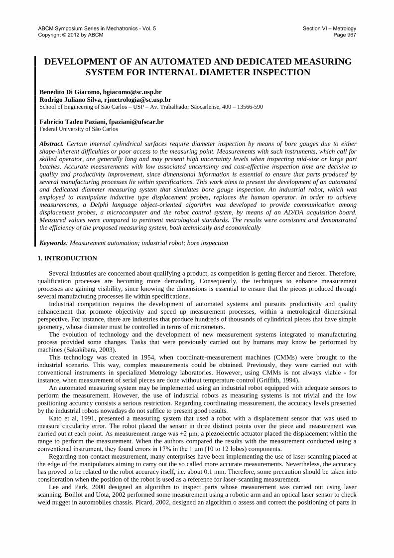
Figure 1 shows the automated system for the proposed measure in a schematic way:
Figure 1. Automated system for measuring internal diameters (ASMID)
The measuring signals obtained by the displacement transducers are sent to the measurement column. This column
converts the digital-analogical data and sent it to the computer to be analyzed. An analogical-digital (AD)/digital-
analogical (DA) conversion module is responsible for the interface between the measurement equipments and the data
gathering routine.
A six-axes industrial robot is programmed and prepared so communication with external systems is possible. The
model used in this experiment was ABB’s IRB140. It was designed for manufacturers that use automation based on
robotic systems.
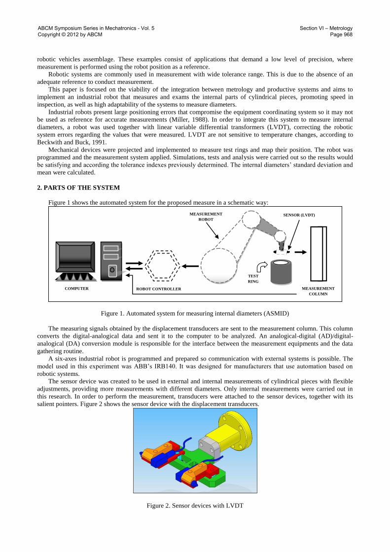
The sensor device was created to be used in external and internal measurements of cylindrical pieces with flexible
adjustments, providing more measurements with different diameters. Only internal measurements were carried out in
this research. In order to perform the measurement, transducers were attached to the sensor devices, together with its
salient pointers. Figure 2 shows the sensor device with the displacement transducers.
Figure 2. Sensor devices with LVDT
TEST
RING
TESTE
COMPUTER ROBOT CONTROLLER
SENSOR (LVDT) MEASUREMENT
ROBOT
MEASUREMENT
COLUMN
ABCM Symposium Series in Mechatronics - Vol. 5 Copyright © 2012 by ABCM
Section VI – Metrology Page 968
The demodulation of the analogical measurement signal provided by the displacement sensors (LVDT) was
performed through the measurement column TESA TT500. The communication between the column and the data
acquisition board is established through a parallel cable.
A piece case was designed to place the piece in such a way that there was enough room for the sensors. In addition,
this case provides the piece steadiness and places it in an adequate position to be measured. The case was attached to a
table made of granite which enhanced the stability and alignment of the piece.
In order to calibrate the system a Mitutoyo ring was used. Its internal diameter is 69.995 mm. Two test rings were
made and their internal measures were slightly different: 69.945mm and 70.045mm. The other rings had dimensions
that were similar to the ring gauge.
3. THE EXPERIMENT
An online program was used to move the robot. It consisted of a manual controller to place the robot in the working
area. Each programming instruction to manipulate the robot was regarding the path, position, displacement speed, tools,
and the dimension of the precision area.
In order to diminish the calibration time consuming for ring gauge and the measurement of the test rings, the
distance between the robot and the piece must be aligned. This will minimize the movements performed by the
manipulator inside the ring.
The tool central point (TCP) of the manipulator was defined. When TCP is determined, the information obtained
from the manipulator wrist coordinating system (xyz) is stored and transferred to the base of wrist. This way,
programming the robot movements is feasible. The measurement of the internal diameters of the rings was carried out.
It was possible after determining TCP, aligning the sensor device and designing the computer program.
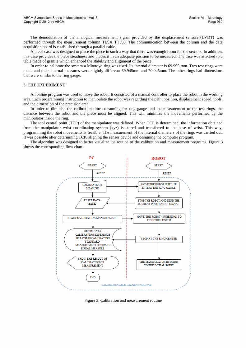
The algorithm was designed to better visualize the routine of the calibration and measurement programs. Figure 3
shows the corresponding flow chart.
Figure 3. Calibration and measurement routine
ABCM Symposium Series in Mechatronics - Vol. 5 Copyright © 2012 by ABCM
Section VI – Metrology Page 969

The standard measure ( ) enters the measuring program and is shown at the screen. The standard value used
is equal to 69.995mm. The LVDT calibration difference ( ) is obtained after the end of the translation
movement during the calibration and is equal to the “zeroed” standard. The variation ( ) is obtained after the
end of the translation movement during the measurement, and is equal to the difference between LVDT measure
(obtained during the measurement routine) in relation to the LVDT measure (obtained during the calibration routine).
The measurement equation obtained by the transducers to carry out the real measurement ( ) is shown
below:
(1)
The measurement procedure is similar to that of a comparator bore gauge. Thus, the first step consists of calibrating
the sensors using the ring gauge. The sensors are moved to the inner part of the ring gauge and translation movements
are performed (See figure 4).
Figure 4. The robotic translation movement
The translation movement makes sure the sensors determine the largest distance between two points in the internal
circumference of the ring gauge. It corresponds to the calibration of the comparator bore gauge.
Calibration and measurement were carried out according to the following steps:
The beginning of the movement from the programmed starting point;
The robot moves so the sensors are adjusted inside the ring gauge. The manipulator moves towards the inner
part of the ring and the robot starts the measurement;
The robot moves back to the starting point. This is the end of the movement.
After calibration is performed, the ring gauge is substituted for the test ring. The same procedure is undergone.
The result is shown automatically on the graphic measurement interface. There is a free slot in this interface where
the name of the piece is written. The measurement data is transferred to a sequential data bank.
The measurement of the test rings and the ring gauge were done considering the following measurement devices:
internal micrometer with three pointers, comparator bore gauge, coordinating measurement tridimensional machine.
4. RESULTS
The results were compared with the proposed system.
The ring gauge was calibrated using Máquina Universal SIP – Model 302M. The results obtained after measuring
the diameters of the standard and test rings five times are shown in table 1.
TRANSLATION
MOVEMENT
ABCM Symposium Series in Mechatronics - Vol. 5 Copyright © 2012 by ABCM
Section VI – Metrology Page 970
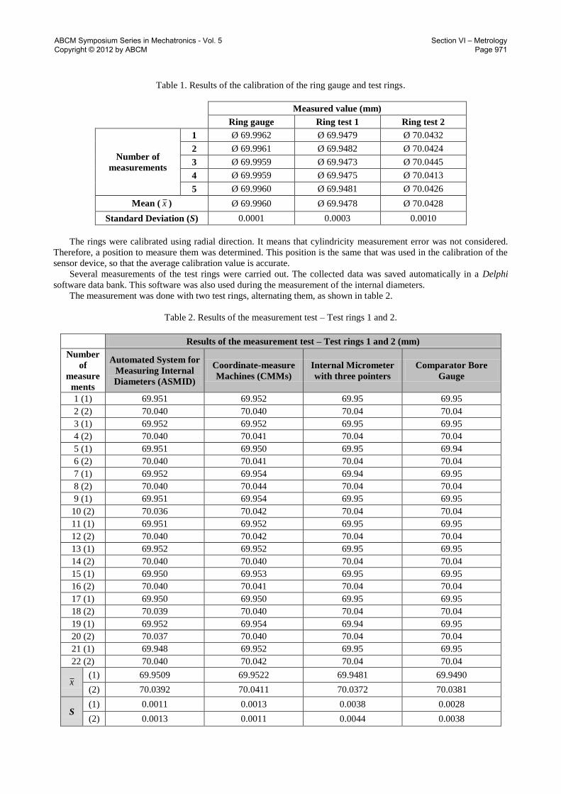
Table 1. Results of the calibration of the ring gauge and test rings.
Measured value (mm)
Ring gauge Ring test 1 Ring test 2
Number of
measurements
1 Ø 69.9962 Ø 69.9479 Ø 70.0432
2 Ø 69.9961 Ø 69.9482 Ø 70.0424
3 Ø 69.9959 Ø 69.9473 Ø 70.0445
4 Ø 69.9959 Ø 69.9475 Ø 70.0413
5 Ø 69.9960 Ø 69.9481 Ø 70.0426
Mean ( x ) Ø 69.9960 Ø 69.9478 Ø 70.0428
Standard Deviation (S) 0.0001 0.0003 0.0010
The rings were calibrated using radial direction. It means that cylindricity measurement error was not considered.
Therefore, a position to measure them was determined. This position is the same that was used in the calibration of the
sensor device, so that the average calibration value is accurate.
Several measurements of the test rings were carried out. The collected data was saved automatically in a Delphi
software data bank. This software was also used during the measurement of the internal diameters.
The measurement was done with two test rings, alternating them, as shown in table 2.
Table 2. Results of the measurement test – Test rings 1 and 2.
Results of the measurement test – Test rings 1 and 2 (mm)
Number
of
measure
ments
Automated System for
Measuring Internal
Diameters (ASMID)
Coordinate-measure
Machines (CMMs)
Internal Micrometer
with three pointers
Comparator Bore
Gauge
1 (1) 69.951 69.952 69.95 69.95
2 (2) 70.040 70.040 70.04 70.04
3 (1) 69.952 69.952 69.95 69.95
4 (2) 70.040 70.041 70.04 70.04
5 (1) 69.951 69.950 69.95 69.94
6 (2) 70.040 70.041 70.04 70.04
7 (1) 69.952 69.954 69.94 69.95
8 (2) 70.040 70.044 70.04 70.04
9 (1) 69.951 69.954 69.95 69.95
10 (2) 70.036 70.042 70.04 70.04
11 (1) 69.951 69.952 69.95 69.95
12 (2) 70.040 70.042 70.04 70.04
13 (1) 69.952 69.952 69.95 69.95
14 (2) 70.040 70.040 70.04 70.04
15 (1) 69.950 69.953 69.95 69.95
16 (2) 70.040 70.041 70.04 70.04
17 (1) 69.950 69.950 69.95 69.95
18 (2) 70.039 70.040 70.04 70.04
19 (1) 69.952 69.954 69.94 69.95
20 (2) 70.037 70.040 70.04 70.04
21 (1) 69.948 69.952 69.95 69.95
22 (2) 70.040 70.042 70.04 70.04
x (1) 69.9509 69.9522 69.9481 69.9490
(2) 70.0392 70.0411 70.0372 70.0381
S (1) 0.0011 0.0013 0.0038 0.0028
(2) 0.0013 0.0011 0.0044 0.0038
ABCM Symposium Series in Mechatronics - Vol. 5 Copyright © 2012 by ABCM
Section VI – Metrology Page 971

5. CONCLUSION
The measurement of the internal diameters for serial pieces using the automated system (ASMID) proved to be
more viable than the other measurement methods in terms of flexibility, measurement process automation, precision,
measurement time consuming and access to the measurement area.
The flexibility of the sensor device makes internal and external diameter measurements possible for several ranges.
The presence of a human operator is not necessary since the process is automated. The automated system enhances
productivity as the measurement process is not interrupted. The cost of the automated system is lower if compared to a
CNC machine measurement.
The degree of accuracy of the automated system is higher than the ones provided by conventional instruments,
micrometer and comparator bore gauge. This is due to the use of displacement transducers (LVDT) and the
measurement column that offers 1 µm resolution.
Measurement time consuming in the proposed system is lower than that of the coordinate-measurement machines
because the first does not need to be prepared to measure.
6. ACKNOWLEDGEMENTS
We would like to thank the Metrology Laboratory at LAMAFE – EESC/USP for allowing the development of this
research.
7. REFERENCES
Griffith, G.K. (1994). Measuring & gaging geometric tolerances. Englewood Cliffs, New Jersey: Prentice Hall Career
and Technology.
Beckwith, T.G.; and Buck, N. L. (1991). Mechanical Measurements. Reading, Massachussets: Addison-Wesley.
Boillot, J.P.; Uota, K. (2002). Flexible robotic measuring of weldments on production lines. Industrial Robot: An
International Journal, v.29, n.1, p.43-48.
Kato, H.; Sone, R.Y.; Nomura, Y. (1991). In-situ measuring system of circularity using an industrial robot and a
piezoactuator. International Journal of the Japan Society of Precision Engineering, v.25, n.2, p.130-135.
Lee, K.H.; Park, H.P. (2000). Automated inspection planning of free-form shape parts by laser scanning. Robotics and
Computer Integrated Manufacturing, v.16, n.4, p.201-210.
Miller, Rex (1988). Fundamentals of industrial robots and robotics. Boston: State University College at Buffalo.
Picard, M.P. (2002). Flexplace: watchmaker precision for robotic placement of automobile body parts. Industrial Robot:
An International Journal, v.29, n.4, p.329-333.
Sakakibara, S., (2003), “The Latest Robot Systems Which Reinforce Manufacturing Sector”, Proceedings of the 2003
IEEE International Conference on Robotics & Automation, Taipei, Taiwan, 14-19 September 2003.
ABCM Symposium Series in Mechatronics - Vol. 5 Copyright © 2012 by ABCM
Section VI – Metrology Page 972