development of a new nanostructured scaffold for neural ... · tânia sofia dos santos vieira...
TRANSCRIPT
Tânia Sofia dos Santos Vieira
Mestre em Ciências Biomédicas
Development of a new nanostructured scaffold for neural stem/progenitor cell
transplantation
Dissertação para a obtenção do grau de Doutor em Bioengineering Systems – MIT Portugal Program
Orientador: Dr Célia Henriques, Profª auxiliar, FCT-UNL Co-orientador: Dr João Paulo Borges, Prof auxiliar, FCT-UNL Co-orientador: Dr Ana Sofia Falcão, Pos-doc, CEDOC
Júri:
Presidente: Prof.Doutor Luís Paulo da Silva Nieto Marques Rebelo Arguentes: Profª. Doutora Maria Helena Mendes Gil Doutor Hugo Agostinho Machado Fernandes Vogais: Prof. Doutor António Alfredo Coelho Jacinto Profª. Doutora Maria Helena Figueiredo Godinho Prof. Doutor Frederico Castelo Ferreira Prof. Doutora Célia Maria Reis Henriques Doutora Ana Paula Gomes Moreira Pêgo
Outubro de 2017

ii

iii
Development of a new nanostructured scaffold for neural stem/progenitor cell transplantation
Copyright © Tânia Sofia dos Santos Vieira, Faculdade de Ciências e Tecnologia - Universidade
Nova de Lisboa.
A Faculdade de Ciências e Tecnologia e a Universidade Nova de Lisboa têm o direito, perpétuo
e sem limites geográficos, de arquivar e publicar esta dissertação através de exemplares
impressos reproduzidos em papel ou de forma digital, ou por qualquer outro meio conhecido ou
que venha a ser inventado, e de a divulgar através de repositórios científicos e de admitir a sua
cópia e distribuição com objectivos educacionais ou de investigação, não comerciais, desde
que seja dado crédito ao autor e editor.

iv

v
Acknowledgments
First of all I want to express my gratitude to my thesis advisors, professor Célia Henriques,
professor João Paulo Borges and Ana Sofia Falcão for the presentation of this fascinating
project and their effort to ensure all the necessary conditions for their development. I also thank
their guidance, encouragement and time during these years. I would like to thank to Professor
Jorge Silva for the availability and teaching during the development of this project.
I appreciate the financial support from Fundação para a Ciência e Tecnologia – FCT that funded
the PhD grant - SFRH/BD/90682/2012.
I also want to thank the members of the thesis committee, professor Helena Godinho and
professor Domingos Henrique for their suggestions throughout the development of the work.
I would like to thank to Professor Elvira Fortunato for the opportunity to use the CENIMAT/i3N
research facilities: thanks to Ana Pimentel and Alexandra Gonçalves for DSC/TGA acquisition;
Joana Pinto for XRD acquisition and Daniela Gomes for SEM acquisition.
I would like to express my gratitude to Doctor Cecília Bonifácio, from REQUIMTE – FCT/UNL,
for NMR acquisition and to Professor Ana Rego, from IST, for the XPS acquisition and for their
guidance and help in the interpretation of the results.
I am especially grateful to all the GREAT LAB students that provided moments of fun and laughs
and helped to overcome the difficulties. However, I am indebted to Luisa Fialho, Ana Fradinho,
Zeliha Güler, Carolina Rufino and Ana Nogueira for their friendship and support beyond the lab.
In the Polymers lab, I’d like to thank to Paula Soares, Susete Fernandes and Coro Echeverria
for scientific support and advices, you were always available to help. Augusta thanks for your
affection and happy guffaws. Ana Almeida thanks for the help in contact angle measurements.
I´d like to thank to all the colleagues and students that passed the Polymers Lab for their
contribution to a great lab atmosphere. Special thanks to Mariana Amaro for all the support,
encouragement and friendship.
I am especially grateful to Dr Sharka Kubinova for the opportunity to work in the laboratory of
biomaterials and biophysical methods at Institute of Experimental Medicine AS CR and for their
guidance and teaching. I also would like to thank to Lenka for the help in the lab integration and
in MSCs culture and to Klara for the guidance with the SPC-01 cultures. Thanks to the desktop
colleagues Barbora, Monika, Kristina, Serguei, Jiří and Zuska for support and “oběd” time.
“Děkuji” to all laboratory group.

vi
I want to thank to the MIT Portugal colleagues, especially Andreia Pimenta, Cláudia Saraiva
and Marta Costa, for learning, support and happy moments during the first year of the PhD
program.
I also thank to my friends Sara, Magda and Carla and my sister Ângela for their support and
patience during these last years. Special thanks to my parents for the education, advices,
support and love. Finally, special thanks go to Ricardo for the love, support and understanding.
Thank you for believe in me even when myself did not. Thank you for give me strength and help
me to be a better person.

vii
Abstract
Tissue engineering investigates new therapeutic approaches for spinal cord
regeneration. Biodegradable scaffolds are employed aiming at creating an appropriate
environment to support cell regrowth and transplantation. The transplantation of neural
stem/progenitor cells (NSPCs) is a promising strategy under investigation. The main objective
of this work was the synthesis of new soft materials for the production of nanostructured
scaffolds able to support NSPCs transplantation and enable spinal cord regeneration.
Polyurethanes (PUs) are segmented polymers, with tunable properties. PUs were
synthesized using polycaprolactone-diol (PCL-diol) as soft segment, and isophorone
diisocyanate and dimethylol propionic acid (DMPA) as hard segment. To introduce biological
cues in the polymer backbone, chitosan (CS) and gelatin (Gel) were used to substitute DMPA
as chain extender. The PUs were characterized regarding their chemical composition and
thermal properties.
Electrospun fibrous mats are convenient structures for cell support. In particular, aligned
nanofibers provide a guidance cue to axon regrowth. Electrospinning was used to produce
scaffolds of randomly oriented and aligned fibers from the different PU formulations. Scaffolds
were characterized regarding their morphology, mechanical behavior, crystallinity, surface
properties and hydrolytic degradation. Their impact on cells was evaluated in vitro using human
fibroblasts. Cell adhesion and proliferation was highest for scaffolds produced from PUs
containing CS or Gel as the only chain extender.
Stem cell interaction with PU-CS and PU-Gel scaffolds was studied using human
umbilical cord mesenchymal stem cells (MSCs) and human fetal spinal cord neural stem cells
(NSCs). MSCs proliferated best on PU-Gel randomly oriented fibers whereas NSCs proliferated
best on PU-CS with aligned fiber morphology. Neuronal differentiation of NSCs was confirmed
using neuronal markers. Neurites aligned along the fibers direction.
The physical, chemical and biological properties of PU-CS and PU-Gel fibrous mats
make them promising substrates for NSPC in order to promote neural regeneration.
Keywords: Polyurethanes, Chitosan, Gelatin, Electrospinning, Neural
Stem/progenitor Cells.

viii

ix
Resumo
A engenharia de tecidos investiga novas abordagens para a regeneração da espinal
medula. Estruturas biodegradáveis são usadas para criar um ambiente que suporte o
crescimento e transplante de células. O transplante de células neurais estaminais/progenitoras
(NSPCs) é uma estratégia promissora sob investigação. O principal objetivo deste trabalho foi
a síntese de novos materiais macios para produzir matrizes nano-estruturadas capazes de
suportar o transplante de NSPCs e permitir a regeneração da espinal medula.
Poliuretanos (PUs) são polímeros segmentados, com propriedades ajustáveis.
Foram sintetizados PUs utilizando policaprolactona-diol como segmento macio, e diisocianato
de isoforona e ácido dimetilol propiónico (DMPA) como segmento duro. Para introduzir sítios
para interação biológica na estrutura do polímero, foram utilizados quitosano (CS) e gelatina
(Gel) substituindo o DMPA. Os PUs foram caracterizados química e termicamente.
Matrizes fibrosas eletrofiadas, são estruturas convenientes para o suporte celular.
Em particular, nanofibras alinhadas guiam o crescimento dos axônios. Matrizes de fibras
orientadas aleatoriamente e alinhadas dos diferentes Pus foram obtidas por eletrofiação e
caracterizadas quanto à morfologia, comportamento mecânico, cristalinidade, propriedades de
superfície e degradação hidrolítica. O seu impacto nas células foi avaliado in vitro utilizando
fibroblastos humanos. A adesão e proliferação celular foram mais elevadas nas matrizes de
PUs contendo CS ou Gel como único extensor de cadeia.
A interação de células estaminais com matrizes de PU-CS e de PU-Gel foi estudada
usando células humanas estaminais mesenquimais do cordão umbilical (MSCs) e células
estaminais neurais da espinal medula fetal (NSCs). As MSCs proliferaram melhor nas fibras
orientadas aleatoriamente de PU-Gel, enquanto as NSCs proliferaram melhor em matrizes de
fibras alinhadas de PU-CS. A diferenciação neuronal das NSCs foi confirmada usando
marcadores neuronais. As neurites alinharam ao longo das fibras.
As propriedades físicas, químicas e biológicas das matrizes de PU-CS e PU-Gel
tornam-nas substratos promissores para NSPCs, na promoção da regeneração neural.
Palavras-chave: Poliuretanos, Quitosano, Gelatina, Electrofiação, Células Neurais
Estaminais/progenitoras.

x

xi
Table of Contents
Abstract ..................................................................................................................................... vii
Resumo ...................................................................................................................................... ix
List of Figures ............................................................................................................................ xv
List of Tables ............................................................................................................................ xix
List of Acronyms ....................................................................................................................... xxi
1. Introduction ........................................................................................................................ 2
2. Literature Review............................................................................................................... 8
2.1 Spinal Cord Injury ........................................................................................................ 8
2.1.1 Primary injury ....................................................................................................... 8
2.1.2 Secondary injury .................................................................................................. 8
2.2 Limited spinal cord regeneration capacity ................................................................. 10
2.3 Therapeutic/regenerative strategies .......................................................................... 11
2.3.1 Drugs ................................................................................................................. 12
2.3.2 Stem cells therapy ............................................................................................. 13
2.3.3 Tissue engineering ............................................................................................ 14
2.4 Interaction of scaffolds with NSPCs .......................................................................... 21
2.4.1 In vitro studies ................................................................................................... 21
2.4.2 In vivo studies .................................................................................................... 25
2.5 Role of scaffold topography in stem cell differentiation ............................................. 26
2.5.1 Nano/micro-scale scaffolds ............................................................................... 28
2.5.2 Self-assembly nanofibers .................................................................................. 28
2.5.3 Phase separation fibrillar structures .................................................................. 30
2.5.4 Lithographic patterned substrates ..................................................................... 30
2.5.5 Carbon-based nanomaterials ............................................................................ 32
2.5.6 Electrospinning .................................................................................................. 32
2.6 References ................................................................................................................ 45
3. Electrospun biodegradable chitosan based-poly(urethane urea) scaffolds for soft
tissue engineering ................................................................................................................... 60
3.1 Introduction ................................................................................................................ 60

xii
3.2 Materials and methods .............................................................................................. 62
3.2.1 Depolimerization of chitosan and determination of molecular weight ............... 62
3.2.2 Synthesis of Polyurethane extended with chitosan ........................................... 63
3.2.3 Characterization of synthesized polyurethanes ................................................ 63
3.2.4 Electrospinning and film casting ........................................................................ 64
3.2.5 Physico-chemical characterization of fibrous mats and films ............................ 65
3.3 Results and Discussion ............................................................................................. 69
3.3.1 Depolymerization of Chitosan ........................................................................... 69
3.3.2 Polyurethanes Characterization ........................................................................ 70
3.3.3 Optimization of the electrospinning process ..................................................... 79
3.3.4 Characterization of the electrospun nanofibers ................................................. 82
3.3.5 Aligned vs. random electrospun mats ............................................................... 97
3.4 Conclusions ............................................................................................................. 104
3.5 References .............................................................................................................. 104
4. A new biodegradable gelatin based-poly(ester urethane urea): synthesis,
characterization and electrospun scaffolds for soft tissue engineering......................... 112
4.1 Introduction .............................................................................................................. 112
4.2 Materials and methods ............................................................................................ 113
4.2.1 Synthesis of PU-Gel ........................................................................................ 113
4.2.2 Characterization:of PU-Gel ............................................................................. 114
4.2.3 Electrospinning and film casting ...................................................................... 114
4.2.4 Characterization of PU-Gel electrospun fibers ................................................ 115
4.3 Results and discussion ............................................................................................ 117
4.3.1 PU-Gel Characterization.................................................................................. 117
4.3.2 Characterization of fiber mats ......................................................................... 123
4.3.3 Random vs Aligned fibrous mats ..................................................................... 131
4.4 Conclusion ............................................................................................................... 135
4.5 References .............................................................................................................. 135
5. Biocompatibility evaluation of electrospun mats from chitosan or gelatin based
poly(urethane urea) ............................................................................................................... 140
5.1 Introduction .............................................................................................................. 140
5.2 Materials and methods ............................................................................................ 141

xiii
5.2.1 Materials .......................................................................................................... 141
5.2.2 Characterization of polyurethanes ................................................................... 142
5.2.3 Production of fibrous mats ............................................................................... 142
5.2.4 Characterization of fibrous mats ...................................................................... 142
5.2.5 Cell culture experiments .................................................................................. 143
5.3 Results and discussion ............................................................................................ 146
5.3.1 PU-CS and PU-Gel characterization ............................................................... 146
5.3.2 Fibrous mats characterization ......................................................................... 147
5.3.3 Proliferation of 3T3 fibroblasts ......................................................................... 151
5.3.4 MSCs adhesion and proliferation on fibrous mats .......................................... 152
5.3.5 NSCs proliferation on the fibrous mats ............................................................ 156
5.4 Conclusion ............................................................................................................... 161
5.5 References .............................................................................................................. 162
6. Conclusions and Future Work ..................................................................................... 166
6.1 Conclusions ............................................................................................................. 166
6.2 Future Work ............................................................................................................. 169
6.3 References .............................................................................................................. 170

xiv

xv
List of Figures
Chapter 2
Figure 2.1 – Pathophysiological events occurring after SCI, including the primary, secondary
and chronic phases. .................................................................................................................. 10
Figure 2.2 – Constituents and route of production of PUs. ....................................................... 18
Figure 2.3 – Cells mechanosensors are stimulated by external mechanical forces. ................ 27
Figure 2.4 – Scheme of the electrospinning setup. ................................................................... 34
Chapter 3
Figure 3.1 – IR spectra of CS before and after depolymerization. ............................................ 70
Figure 3.2 – Chemical structure of PU-DMPA/CS showing the urea bond between IPDI and the
amine group of CS. ................................................................................................................... 71
Figure 3.3 – 1H NMR spectra of PCL-diol and IPDI used in the chemical synthesis of PUs. ... 72
Figure 3.4 – 1H NMR spectra of the synthetized PUs. .............................................................. 72
Figure 3.5– FTIR spectra of the precursors and the intermediate pre-polymer to reach PU-
DMPA/CS. ................................................................................................................................. 74
Figure 3.6– FTIR spectra of the synthetized PUs. .................................................................... 74
Figure 3.7 – Carboxyl region (1600 – 1800 cm-1) of PU-CS IR spectrum: Absorbance spectrum
(A); second-derivative spectrum (B). ......................................................................................... 75
Figure 3.8– ATR-FTIR spectra in the carbonyl group stretching and the deconvoluted curves of
(A) PU-DMPA, (B) PU-DMPA/CS and (C) PU-CS. ................................................................... 76
Figure 3.9– ATR-FTIR spectra in the amine group stretching and the deconvoluted curves of(A)
PU-DMPA, (B) PU-DMPA/CS and (C) PU-CS. ......................................................................... 77
Figure 3.10 – Mass losses (A) and the corresponding derivatives (B) vs. temperature of PCL-
diol, CS, PU-DMPA, PU-DMPA/CS and PU-CS. ...................................................................... 78
Figure 3.11 – DSC curves of PCL-diol, CS and PUs with an increasing CS content substituting
DMPA as chain extender. .......................................................................................................... 79
Figure 3.12 – SEM images of the electrospun fibers produced from 20% PU-DMPA/CS solution
with THF:DMF at different ratios. .............................................................................................. 81
Figure 3.13– SEM images of the electrospun fibers produced from PU-DMPA/CS solution at
different concentrations with 50:50 THF:DMF solvent system. ................................................. 81
Figure 3.14 – SEM images of electrospun fibrous matrices produced from PU-DMPA, PU-
DMPA/CS and PU-CS and their respective fiber diameter histograms. ................................... 83
xvi
Figure 3.15– Tensile response curves of the electrospun nanofibrous matrices produced from
PU-DMPA, PUU-DMPA/CS and PU-CS. .................................................................................. 84
Figure 3.16– Hyteresis loops after 10 cycles stretching and recovering of electrospun fibrous
mats. .......................................................................................................................................... 85
Figure 3.17 – X-Ray diffractograms of PCL-diol, CS, and films and fiber mats from PU-DMPA,
PU-DMPA/CS and PU-CS. ........................................................................................................ 86
Figure 3.18– Fitting of the characteristic peaks of the PU-DMPA/CS fibrous mat diffractogram
with Voigt functions (red) and a cubic background (green). ...................................................... 87
Figure 3.19 – The C1s, N1s and O1s XPS spectra and the respective fitted peaks for PU-CS
films (top line) and fibrous mats (botoom line) at 0º take-off angle.. ......................................... 88
Figure 3.20– Water contact angle values for the PUs films and mats and the respective water
drop images. .............................................................................................................................. 91
Figure 3.21 – Hydrolitic degradation of PU films (F_) and fibrous mats (M_) produced from the
synthetized PUs immersed in PBS (A) and in lipase solution (B). ............................................ 92
Figure 3.22 – FTIR spectra of PU-DMPA, PU-DMPA/CS and PU-CS films and fibrous mats after
degradation in PBS and in lipase solution. ................................................................................ 93
Figure 3.23– Results of HFFF2 cells’ viability, obtained in a cytotoxicity assessment of PU-
DMPA, PU-DMPA/CS and PU-CS (A) films and (B) electrospun mats. ................................... 94
Figure 3.24– Optical microscope images of the HFFF2 cells seeded in 96 well plate in contact
with pure extracts ...................................................................................................................... 94
Figure 3.25 – HFFF2 cell population. ........................................................................................ 96
Figure 3.26– Fluorescent images of the cells stained with phalloidin (red) and DAPI (blue). .. 97
Figure 3.27 – SEM images of randomly oriented electrospun fibrous mats (column 1) from PU-
DMPA (A), PU-DMPA/CS (B) and PU-CS (C), and the respective histograms of the fiber
diameter (column 2) and the angular distribution (column 3). ................................................... 99
Figure 3.28– SEM images of aligned electrospun fibrous matrices (column 1) from PU-DMPA
(A), PU-DMPA/CS (B) and PU-CS (C), and the respective histograms of the diameter (column
2) and the angular distribution (column 3). .............................................................................. 100
Figure 3.29– Stress-strain curves of the electrospun random and aligned fibrous matrices
produced from PU-DMPA, PU-DMPA/CS and PU-CS (A). ..................................................... 101
Figure 3.30– Water contact angle values of the PU-DMPA, PU-DMPA/CS and PU-CS
electrospun fibrous mats with random and aligned morphology after 1 min recording time. .. 102
Figure 3.31 – Viability assay of HFFF2 cells ........................................................................... 103
Figure 3.32 - Fluorescent images of phalloidin (red) and cell nuclei (DAPI, blue) stained HFFF2
cells. ........................................................................................................................................ 104

xvii
Chapter 4
Figure 4.1– Synthesis route of polyurethane based gelatin. ................................................... 114
Figure 4.2– 1H NMR spectra of PU-Gel 1.0 g and its precursors in the range between 0.5 ppm
to 5.0 ppm. ............................................................................................................................... 118
Figure 4.3– FTIR spectra of PUs synthetized with different amounts of gelatin and their
constituents. ............................................................................................................................ 119
Figure 4.4– C=O stretching band analysis for PU-Gel with different gelatin contents: (A) 5%; (B)
7.5%; (C) 10%. ........................................................................................................................ 120
Figure 4.5 – N-H stretching band analysis for PU-Gel with different gelatin contents: (A) 5%; (B)
7.5%; (C) 10%. ........................................................................................................................ 121
Figure 4.6– DSC thermograms of PUs synthesized with different amounts of gelatin. .......... 122
Figure 4.7 – Thermal analysis of PU-Gel synthesized with different amounts of gelatin: (A)
thermogravimetric analysis spectra; (B) Derivative weight loss curves. ................................. 123
Figure 4.8 – SEM images of the fibrous mats ......................................................................... 124
Figure 4.9 – SEM images of the fibrous mats produced from PU-Gel-5................................. 125
Figure 4.10 – Typical stress-strain curves of PU-Gel films (F_PU-Gel) and fiber mats (M_PU-
Gel) (A) and the respective hysteresis loops (B and C) after 10 cycles stretching and recovery.
................................................................................................................................................. 126
Figure 4.11 – X-ray diffractograms of PU-Gel film and fibrous mat (A).. ................................ 127
Figure 4.12 – Water contact angle values of the PU-Gel films and electrospun fibrous mats and
the respective water drop images. .......................................................................................... 128
Figure 4.13 – Degradation profile of the PU-Gel films (A) and fibrous mats (B) in PBS, lipase
and trypsin. .............................................................................................................................. 129
Figure 4.14 – Cytotoxicity assessment of HFFF2 cells cultured with extracts from PU-Gel films
and mats at concentrations of 15, 10, and 5 mg/mL. .............................................................. 130
Figure 4.15 – Optical microscope images of the HFFF2 cells seeded in 96 well plate in contact
with pure extracts. ................................................................................................................... 130
Figure 4.16 – (A) Proliferation of HFFF2 cells ......................................................................... 131
Figure 4.17 – SEM images of random (A) and aligned (D) PU-Gel fibrous mats, and the
respective histograms of the fiber diameter distribution (B and E) and the angle distribution (C
and F). ..................................................................................................................................... 132
Figure 4.18 – Stress-strain curves of the random (R_) and aligned (A_) PU-Gel fibrous mats.
................................................................................................................................................. 133
Figure 4.19 – Water contact angle values of random and aligned PU-Gel mats. ................... 133

xviii
Figure 4.20 – Proliferation assay of HFFF2 cells seeded on the electrospun PU-Gel fibrous mats
with random and aligned morphology .................................................................................... 134
Chapter 5
Figure 5.1 – FTIR spectra of PU synthetized with gelatin or chitosan as chain extenders. .... 146
Figure 5.2 – SEM images of the PU-CS (1A, 3A) and PU-Gel (2A, 4A) fibrous mats with random
(1A, 2A) and aligned (3A, 4A) morphology. (B) Histogram of the fiber diameter distribution on
the mats. (C) Histogram with the angular distribution and the pixel intensity (from FFT analysis)
with the acquisition angle for the produced mats. ................................................................... 148
Figure 5.3 – Typical stress-strain curves of random and aligned PU-CS and PU-Gel fibrous mats
under (A) dry and (B) wet conditions. ...................................................................................... 150
Figure 5.4 – Water contact angle values of the electrospun random and aligned PU-CS and PU-
Gel mats and the representative picture of the water drop on the mats’ surface. .................. 151
Figure 5.5 – Resazurin proliferation assay of 3T3 fibroblasts seeded on the electrospun PU-CS
and PU-Gel random and aligned fibrous mats. ....................................................................... 152
Figure 5.6 – The average values of MSCs number (A) and growth area (B) seeded on the
electrospun fibrous mats during 4 h in the presence and the absence of PL in culture medium
................................................................................................................................................. 153
Figure 5.7 – Fluorescent images of immunofluorescent staining for cytoskeleton (phalloidin, red)
and cell nuclei (DAPI, blue) of MSCs seeded on electrospun fibrous mats ............................ 155
Figure 5.8 - Microscopic fluorescent images of NSCs seeded on electrospun nanofibrous mats
from R_PU-CS (a, e), A_PU-CS (b, f), R_PU-Gel (c, g) and A_PU-Gel (d, h) ....................... 157
Figure 5.9 – Scanning electron microscopy images of NSCs seeded on electrospun nanofibrous
mats ......................................................................................................................................... 158
Figure 5.10 – Laser scanning confocal images of NF70 (red) and DAPI (blue) (A – E) and MAP2
(red) and DAPI (blue) (F – J) stained NSCs seeded on electrospun nanofibrous mats. ........ 159
Figure 5.11 – Laser scanning confocal images of NF70 (red) and DAPI (blue) (A – D) and MAP2
(red) and DAPI (blue) (E – H) stained NSCs seeded on electrospun fibrous mats ................ 160

xix
List of Tables
Chapter 2
Table 2.1 – Interaction of 3D scaffolds from different polymers with NSPCs from different
sources. ..................................................................................................................................... 23
Table 2.2 – Effects of the electrospun nanofibers on nerve cells. ............................................ 38
Table 2.3 – Effects of the nanofibers alignment and diameter on the NSCs behavior. ............ 41
Table 2.4 – Effects of the nanofibers functionalization on the NSCs behavior. ........................ 43
Table 2.5 - Effects of the nanofibers conductivity on the NSCs behavior. ................................ 44
Chapter 3
Table 3.1– Electrospinning set-up parameters used in the production of fibrous mats from
synthesized PUs. ....................................................................................................................... 65
Table 3.2 – Wavenumber (v) and relative area (A) of the 5 components of the C=O stretching
band and the percentage of carbonyl hydrogen bonded. ......................................................... 76
Table 3.3 – Wavenumber (v) and relative area (A) of the 3 components of the N-H stretching
band and the percentage of amine hydrogen bonded. ............................................................. 77
Table 3.4– Thermal analysis data of the synthetized polyurethanes ........................................ 79
Table 3.5– Results from XRD and tensile tests of films and fibrous mats.. .............................. 87
Table 3.6 – XPS atomic percentage composition of different PU films and fibers surfaces. .... 89
Table 3.7– Adhesion ratio of HFFF2 cells to films (F_) and fiber mats (M_). ........................... 96
Chapter 4
Table 4.1– Wavenumber (v) and relative area (A) of the 5 components of the C=O stretching
band and the percentage of carbonyl hydrogen bonded. ....................................................... 120
Table 4.2– Frequency (v) and relative area (A) of the 4 components of the N-H stretching band
and the percentage of amine hydrogen bonded. .................................................................... 121
Table 4.3– Thermal analysis data of PU-Gel. From DSC:. ..................................................... 122
Table 4.4 – Results from XRD and tensile tests of PU-Gel films and fibrous mats.. .............. 127
Chapter 5
Table 5.1– Mechanical properties: Young’s modulus (E), elongation at break (Ɛ) and ultimate
tensile stress (σ) of random and aligned PU-CS and PU-Gel fibrous mats evaluated in dry and
wet conditions. ......................................................................................................................... 150

xx

xxi
List of Acronyms
3D Three dimensional space
3T3 3-day transfer, inoculum 3×10⁵ cells
AFM Atomic force microscopy
ATR Attenuated total reflectance
ATP Adenosine triphosphate
BD Butanediol
BDNF Brain-derived neurotrophic factor
BMP4 Bone morphogenic protein
bFGF Basic fibroblast growth factor
cAMP Cyclic adenosine monophosphate
CH3COOH Acetic acid
CH3COONa Sodium acetate
ChABC Chondroitinase ABC
CNS Central nervous system
CNTF Ciliary neurotrophic factor
CNTs Carbon nanotubes
CS Chitosan
CSPGs Chondroitin sulfate proteoglycans
DAPI 4,6-Diamidino-2-Phenylindole dihydrochloride
DD Degree of deacetylation
DHD 2,5-dimethyl-3-hexine-2,5-diol
DMAc Dimethylacetamide
DMEM Dulbecco’s modified Eagle’s medium
DMF N,N-dimethylformamide
DMPA Dimethylol proprionic acid
DOPA 3,4-diihydroxy-L-phenylalanine
DSC Differential scanning calorimetry
DTG Derivative thermo-gravimetric
ECM Extracellular matrix
EDTA Ethylenediaminetetraacetic acid
EGF Epidermal growth factor
EGFR Epidermal growth factor receptor
eFGF Epidermal fibroblast growth factor
ESCs Embryonic stem cells
FAK Focal adhesion kinase
FBS Fetal bovine serum
FFT Fast Fourier Transform

xxii
FGF-2 Fibroblast growth factor 2
FTIR Fourier transform infrared spectroscopy
FWHM Full width at half maximum
GDNF Glial cell line-derived neurotrophic factor
GPC Gel permeation chromatography
HFFF2 Caucasian foetal foreskin fibroblasts
HFP 1,1,1,3,3,3-hexafluoro-2-propanol
1H NMR Proton nuclear magnetic resonance
HPSG Heparan Sulfate proteoglycan
HS Hard segments
IgG Immunoglobulin G
IPDI Isophorone diisocyanate
IKVAV Ile-Lys-Val-Ala.Val amino acid sequence
iPSCs Induced pluripotent stem cells
LDH Lactate dehydrogenase
MAP2 Microtubule-associated protein 2
MAPK Mitogen-activated protein kinase
MDI Methyl di-p-phenyl diisocyanate
MEM Alpha-minimum essential medium
MIDE 2,2’-(methylimino) diethanol
MSCs Mesenchymal stem cells
NaHSO3 Sodium bisulfite
NaNO2 Sodium nitrite
NaOH Sodium hydroxide
NF70 70 kDa Neurofilament
NGF Nerve Growth factor
NMP N-methylpyrrolidone
Nogo-A Neurite outgrowth inhibitor
NSCs Neural stem cells
NSPCs Neural stem/progenitor cells
NT-3 Neurothophin-3
OHT 4-hydroxytamoxifen
PBS Phosphate buffer saline
PCL Polycaprolactone
PCL-diol Polycaprolactone-diol
PDL Poly-D-lysine
PDMS Poly(dimethylsiloxane)
PEDOT Poly(3,4-ethylenedioxythiophene)
PEG Polyethylene glycol
PES Polyethersulfone
xxiii
PHEMA Poly(2-hydroxyethyl methacrylate)
PHPMA Poly[N-2-(hydroxypropyl) methacrylamide]
PL Platelet lysate
PLA Poly(lactic acid)
PLCL Poly[(L-lactide)-co-(Ɛ-caprolactone)]
PLGA Poly(lactic-co-glycolic acid)
PLL Poly-L-lysine
PLLA Poly(L-lactic acid)
PU-CS Polyurethane extended with chitosan
PU-CS/DMPA Polyurethane extended with dimethylol proprionic acid and chitosan
PU-DMPA Polyurethane extended with dimethylol proprionic acid
PU-Gel Polyurethane extended with gelatin
PUs Polyurethanes
RADA-16 Ac-(Asp-Ala-Asp-Ala)4-CONH2 peptide
REST RE-1 silencing transcriptional factor
SCI Spinal cord Injury
SEM Scanning electron microscopy
SiRNA Small interference ribonucleic acid
SPC-01 Conditionally immortalized neural stem cell line derived from human fetal
spinal cord tissue
SS Soft segments
STEP Spinneret based tunable engineered parameters
TCP Tissue culture plate
TEA Triethylamine
TGA Thermogravimetric analysis
THF Tetrahydrophuran
TMS Tetramethylsilane
TrkC Tropomyosin receptor kinase C
UV Ultraviolet
VEGF Vascular endothelial growth factor
WCA Water contact angle
WST-1 [2-(2-methoxy-4-nitrophenyl)-3-(4-nitrophenyl)-5-(2,4-disulfophenyl)-2H-
tetrazolium, monosodium salt]
XPS X-ray photoelectron spectroscopy
XRD X-ray diffraction
Symbols
A1655 Absorption band at 1655 cm-1
A3450 Absorption band at 3450 cm-1
α Constant dependent on the solution (solute-solvent system) and temperature

xxiv
β Full width at half maximum
Y Young modulus
ΔHm Enthalpy of fusion
Ɛr Elongation at break
[ƞ] Intrinsic viscosity,
θ Diffraction angle
Ia Area of the diffraction peaks resulting from the amorphous reflections
Ic Area of the diffraction peaks resulting from the crystalline reflections
K Constant dependent on the solution (solute-solvent system) and temperature
λ Wavelength
Mv Viscosimetric molecular weight
σ600. Tensile stress at 600% strain
ρ Density
τ Crystallite size
Tg Glass transition temperature
Thard Degradation temperatures of soft segments
Tm Melting temperature
Tsoft Degradation temperatures of soft segments
W1 Specific gravity bottle weight filled with water
W2 Specific gravity bottle weight with water and scaffold
W3 Specific gravity bottle weight after removal of water-saturated matrix from W2
Wc,x Crystalline degree
Wi Initial mass
Wk Remaining mass
Ws Scaffold weight

xxv

xxvi

Chapter 1
Introduction

Chapter 1
2
1. Introduction
Spinal cord injury (SCI), either traumatic or non-traumatic in origin, represent a major health
problem affecting not only the patient but also their family and the community. After the injury,
loss of nervous tissue and consequently loss of motor and sensory function often produce
permanent disabilities such as respiratory failure, pressure sores and autonomic dysreflexia,
resulting in complete or partial paralysis (Thuret, Moon et al. 2006; Madigan, McMahon et al.
2009). Worldwide, it is estimated that 2.5 million people live with SCI, with more than 130,000
new SCI reported each year (International Campaign for Cures of Spinal Cord Injury Paralysis,
website: http://www.campaignforcure.org/). The main causes of SCI are road traffic accidents,
falls, violence and sports activities (Injury 2005), which affects mainly young people with ages
between 15 and 29 years (Van den Berg, Castellote et al. 2010). Less than 1% of people who
suffered from some type of SCI can recover complete neurological function (Injury 2005).
Unfortunately, there are no actual clinical treatment for this disability. Pain reliefs and
surgical decompression are the only procedures realized in clinics, depending on the type of
injury, but they are far from ideal to promote the functional regeneration. The transplantation of
functional stem cells, mainly neural stem cells (NSCs), to the injury site can lead to minimal
improvements at the sensory-motor functions (Tsukamoto, Uchida et al. 2013). However, a few
cells survive in the inhospitable injury environment and their differentiation is not controlled.
Tissue engineering has been working out in a new therapeutic regenerative approach for the
treatment of damaged or missing tissues or organs. In this approach, engineered scaffolds are
aimed at creating an appropriate environment to support endogenous cell regrowth and a possible
cell transplantation from exogenous sources. Recent studies have point out the implantation of
scaffolds as a vehicle for NSCs transplantation as a promising therapeutic strategy to fill in the
injury site and promote the spinal cord regeneration (Saglam, Perets et al. 2013; Li, Liu et al.
2016). However, the role of the scaffolds is far beyond that. A scaffold may provide chemical cues
(type of polymer and/or functionalization) (Ren, Zhang et al. 2009), mechanical properties (Leipzig
and Shoichet 2009) and topographical cues (nano and micro scale topographies)
(Kerativitayanan, Carrow et al. 2015) to influence stem cell behavior. Therefore, gather in a
scaffold all the characteristics that act in synergy to support the differentiation of NSCs in
functional neurons that extent axons over significant distances and form synapses with the host
neurons around the injury site is still a challenge.
The goal of this project was to develop a tissue engineering approach to produce an
electrospun mat to guide the NSCs. The stem cells respond to the substrate chemical cues as
well as to the micro and nanotopography, similar to the extracellular matrix (ECM), which
determine their fate. With this idea, three main tasks were performed: (1) develop new
biocompatible and biodegradable polyurethanes, (2) process those polyurethanes with the
electrospinning technique to get fibrous mats, and (3) evaluate the effect of the chemical and
topographic cues on the NSPCs.

Chapter 1
3
In chapter 2 the SCI problem is described and an overview of the polymers used in tissue
engineering scaffolds for spinal cord repair are exposed. The benefits of use scaffolds seeded
with NSCs were also detailed. Finally, the effect of the scaffolds topographic and chemical cues
were also addressed.
Different techniques were used to create scaffolds with a structure similar to the ECM:
phase separation, self-assembly peptide nanofibers and electrospinning. From those,
electrospinning has been investigated in the construction of conduits that not only fill in the injury
and bridge the lesion site but also contain the topographical signals essential to provide contact
guidance to host cells infiltration and axonal outgrowth (Liu, Houle et al. 2012). The easy control
over the fiber alignment and diameter as well as their functionalization, make the fibrous
substrates suitable to support NSCs (Lim, Liu et al. 2010). The polyurethanes (PUs) are polymers
whose their properties can be easily tunable. Therefore, PUs can be designed to have customized
chemistry and mechanical properties, resulting in promising biomaterials for a wide range of tissue
engineering applications (Guelcher 2008). Electrospun mats from designed PUs are promising
substrates for stem cell support in order to promote blood vessels replacement (Wang, Li et al.
2013) and tendon/ligament regeneration (Cardwell, Dahlgren et al. 2012). However, for spinal
cord, there are no reports designing and processing through electrospinning a tunable PU to get
mats that support and induce the differentiation of NSCs.
To overcome this gap, in chapter 3 is described the synthesis of PUs extended with
dimetlylol proprionic acid (DMPA), DMPA and chitosan (CS) and CS, which were characterized
with spectroscopic techniques and thermal analysis. CS is widely used in biomedical applications
due to its biocompatibility, biodegradability and antimicrobial, antimicrobial, antioxidant and
hemostatic properties (Dash, Chiellini et al. 2011). In neural regeneration, CS has been explored
as a suitable biomaterial for neural differentiation (Du, Tan et al. 2014). It is also described the
optimization of the electrospinning process in order to get mats from the synthetized PUs with
random and aligned morphology. Their morphology, mechanical properties, degradation profile,
wettability and cytotoxicity were evaluated. The mats were also seeded with caucasian foetal
foreskin fibroblasts (HFFF2) cells and the adhesion and proliferation of the cells on the mats was
evaluated.
In the chapter 4, and similarly to the chapter 3, is described the synthesis and
characterization of the PUs extended with gelatin. The gelatin quantity was adjusted to render a
polymer suitable for electrospinning. Gelatin is a biocompatible and biodegradable natural
polymer derived from the hydrolysis and denaturation of collagen, with motifs for cell adhesion
and prolileration (Kang, Tabata et al. 1999). However, gelatin is water soluble and their use as
scaffold requires an additional crosslinking step. The crosslinking agents are toxic and can left
toxic residues in the gelatin scaffolds, which can also impair their structure (Amadori, Torricelli et
al. 2015). The incorporation of the gelatin in the PU structure prevent that. The electrospinning
parameters for the synthetized PUs were optimized. The resulting mats with random and aligned

Chapter 1
4
morphology were characterized according to mechanical properties, degradation profile,
wettability and cytotoxicity. The adhesion and proliferation of HFFF2 fibroblasts in the mats was
also studied.
In the chapter 5, the ability of the mats from PUs extended with either chitosan or gelatin
to support human mesenchymal stem cells (MSCs) and NSCs is evaluated. Mats were seeded
with human MSCs and adhesion and proliferation assay as well as fluorescent staining was
performed to evaluate the viability of those cells on the mats. Human NSCs were also seeded
on the mats and their proliferation was evaluated. In addition, the ability of the cells to differentiate
in neurons on the mats, without additional biomolecules, was evaluated by immnufluorescent
analysis.
Finally, the conclusions of this study are described in chapter 6. The results demonstrate
the feasibility of the electrospun mats to support human mesenchymal and neural stem cells.
Further research on the field is also described.
References
Amadori, S., P. Torricelli, et al. (2015). "Effect of sterilization and crosslinking on gelatin films." Journal of Materials Science: Materials in Medicine 26(2): 1-9.
Cardwell, R. D., L. A. Dahlgren, et al. (2012). "Electrospun fibre diameter, not alignment, affects mesenchymal stem cell differentiation into the tendon/ligament lineage." Journal of tissue engineering and regenerative medicine 8(12): 937–945.
Dash, M., F. Chiellini, et al. (2011). "Chitosan—A versatile semi-synthetic polymer in biomedical applications." Progress in polymer science 36(8): 981-1014.
Du, J., E. Tan, et al. (2014). "Comparative evaluation of chitosan, cellulose acetate, and polyethersulfone nanofiber scaffolds for neural differentiation." Carbohydrate polymers 99: 483-490.
Guelcher, S. A. (2008). "Biodegradable polyurethanes: synthesis and applications in regenerative medicine." Tissue Engineering Part B: Reviews 14(1): 3-17.
National Spinal Cord Injury Statistical Center. (2005). "Spinal Cord Ijury. Facts and Figures at a Glance." The Journal of Spinal Cord Medicine 28(4): 379:380.
Kang, H.-W., Y. Tabata, et al. (1999). "Fabrication of porous gelatin scaffolds for tissue engineering." Biomaterials 20(14): 1339-1344.
Kerativitayanan, P., J. K. Carrow, et al. (2015). "Nanomaterials for engineering stem cell responses." Advanced healthcare materials 4(11): 1600-1627.
Leipzig, N. D. and M. S. Shoichet (2009). "The effect of substrate stiffness on adult neural stem cell behavior." Biomaterials 30(36): 6867-6878.
Li, X., S. Liu, et al. (2016). "Training Neural Stem Cells on Functional Collagen Scaffolds for Severe Spinal Cord Injury Repair." Advanced Functional Materials 26(32): 5835-5847.
Lim, S. H., X. Y. Liu, et al. (2010). "The effect of nanofiber-guided cell alignment on the preferential differentiation of neural stem cells." Biomaterials 31(34): 9031-9039.
Liu, T., J. D. Houle, et al. (2012). "Nanofibrous collagen nerve conduits for spinal cord repair." Tissue Engineering Part A 18(9-10): 1057-1066.

Chapter 1
5
Madigan, N. N., S. McMahon, et al. (2009). "Current tissue engineering and novel therapeutic approaches to axonal regeneration following spinal cord injury using polymer scaffolds." Respiratory physiology & neurobiology 169(2): 183-199.
Ren, Y.-J., H. Zhang, et al. (2009). "In vitro behavior of neural stem cells in response to different chemical functional groups." Biomaterials 30(6): 1036-1044.
Saglam, A., A. Perets, et al. (2013). "Angioneural crosstalk in scaffolds with oriented microchannels for regenerative spinal cord injury repair." Journal of Molecular Neuroscience 49(2): 334-346.
Thuret, S., L. D. Moon, et al. (2006). "Therapeutic interventions after spinal cord injury." Nature Reviews Neuroscience 7(8): 628-643.
Tsukamoto, A., N. Uchida, et al. (2013). "Clinical translation of human neural stem cells." Stem Cell Res Ther 4(4): 102.
Van den Berg, M., J. Castellote, et al. (2010). "Incidence of spinal cord injury worldwide: a systematic review." Neuroepidemiology 34(3): 184-192.
Wang, F., Z. Li, et al. (2013). "Fabrication of mesenchymal stem cells-integrated vascular constructs mimicking multiple properties of the native blood vessels." Journal of Biomaterials Science, Polymer Edition 24(7): 769-783.

Chapter 1
6

Chapter 2
Literature Review

Chapter 2
8
2. Literature Review
2.1 Spinal Cord Injury
Spinal cord has well-characterized descending and ascending tracts. The ascending tracts
are the ones that receive the sensorial inputs and the descending tracts are responsible for a rich
variety of quantifiable motor outputs, ranging from simple reflexes to more complex motor
patterns, such as scratching, fast paw shake and locomotion (Rossignol and Frigon 2011). In a
devastating condition (physical or mechanical trauma) the ascending and/or descending
pathways, which connects the brain to the rest of the body, are disrupted. This phenomenon
results in a large damage to the spinal cord, leading to paralysis and loss of sensation below the
level of injury (Ghosh, Haiss et al. 2009). The initial trauma – primary injury is followed by the
secondary injury, consisting of several events including the loss of neuronal and glial cells, which
culminates with the formation of cystic cavities and glial scars (Figure 2.1).
2.1.1 Primary injury
The primary injury emerges from the initial physical and/or mechanical trauma to the spinal
cord and surrounding vertebral column, caused by blunt impact, compression and penetrating
trauma. Blunt impact comes mainly from falls or collisions; compression from hyperflexion,
hyperextension, axial loading and severe rotation; and penetrating trauma usually arise from
gunshots and stab wounds (Viano, King et al. 1989; Dubendorf 1999; Hulsebosch 2002). After
immediate mechanical damage, a cascade of events such as blood vessel damage, dislocation
of bones, rupture of intervertebral discs, injury to ligaments and cease of blood flow that deprive
the spinal cord of oxygen and nutrients takes place, leading to immediate cell necrosis at the point
of impact (Hulsebosch 2002). Without any treatment, the cells and axons in the spinal cord that
were not affected by the primary injury can be damaged by secondary injury events spreading to
the surrounding tissue (Wang, Zhai et al. 2011).
2.1.2 Secondary injury
The secondary injury is characterized by the events that take place within the spinal cord
in response to the primary injury. Those events propagate from the site of injury to unaffected
areas of the spinal cord and include:
1- Ischemia and micro-vascular damage, comprising vasospasm, thrombosis, hemorrhage
and increased permeability that combined with edema lead to hypoperfusion and necrosis (Tator
and Fehlings 1991; Winkler, Sharma et al. 2002; Samadikuchaksaraei 2007).
2- Glutamatergic excitotoxicity, resulting from the accumulation of excitatory
neurotransmitters due to the failure of the adenosine triphosphate (ATP)-dependent ion pumps,

Chapter 2
9
conducting to the depolarization of the neuronal membrane potential (McDonald and Sadowsky
2002; Park, Velumian et al. 2004).
3- Oxidative stress, resulting from free radical formation and lipid peroxidation that can
attack membranes and other cell components, disturbing unaffected neurons and
oligodendrocytes (Braughler and Hall 1989; McDonald and Sadowsky 2002).
4- Inflammation, recruitment and activation of inflammatory cells associated with secretion
of cytokines, which contribute to further tissue damage (Dusart and Schwab 1994; Takami,
Oudega et al. 2002).
5- Loss of ionic intracellular balance, increase of the opioids at the injury site, depletion of
energy metabolites, conducting to an anaerobic metabolism, an increase of lactate
dehydrogenase (LDH) activity and an activation of calpains and caspases, culminating in cellular
apoptosis (Samadikuchaksaraei 2007).
After days to weeks from the injury, a fluid filled cystic cavity is formed due to the removal
of injured neurons, their axons and necrotic debris. The cyst is expanded to adjacent spinal cord
areas, increasing the cell dead and loss of neuronal function, mainly the dead of oligodendrocytes
that lead to malfunction and degeneration of the intact axons.
Finally, due to the absence of phagocytic macrophages, a scar is formed not only to
promote wound healing but also to limit the spreading of the injury to unaffected areas. In the
central nervous system (CNS), two types of scar tissue were identified, the fibrous scar in the
core and the glial scar in the surrounding parenchyma. The glial scar is constituted by reactive
astrocytes from self-duplication, oligodendrocyte progenitors and astrocytes derived from the
ependymal cells (presented at the central canal of the spinal cord with the ability of neural stem
cells), which are activated after a lesion (Sabelström, Stenudd et al. 2014). On the other hand,
the fibrotic/inflammatory scar is formed from collagen IV, which result in a meshwork basement
membrane where other ECM compounds and inhibitory molecules can bind. It also has
perivascular fibroblasts that deposit on the basal lamina and form a barrier between the lesion
core and the penumbra (Soderblom, Luo et al. 2013).

Chapter 2
10
Figure 2.1 – Pathophysiological events occurring after SCI, including the primary, secondary and
chronic phases. (reproduced with permission from (Mothe and Tator 2013))
2.2 Limited spinal cord regeneration capacity
The inflammatory events in the acute phase are necessary to prevent infections, clear the
debris tissue and close the blood-brain barrier, restraining the lesion site. However, in the chronic
stage, inflammation, myelin debris and glial scar formation limit the axonal regeneration and
consequently, the capacity of the spinal cord to restore their functions after an injury. The scar
formed after the injury is a hostile environment with inhibitory molecules and proteoglycans
without the ability to support the neuronal cells; therefore, acting as a chemical and physical
barrier to the axonal regeneration (Yiu and He 2006).
The inhibitory molecules released after SCI that limit the spinal cord regeneration are:
myelin-associated proteins that inhibit axonal growth such as, oligodendrocyte myelin protein –
neurite outgrowth inhibitor (Nogo-A), (GrandPré, Nakamura et al. 2000); netrin-1 (Löw,
Culbertson et al. 2008); transmembrane semaphoring Sema4D/CD100 (Moreau-Fauvarque,
Kumanogoh et al. 2003) and ephrin-B3 (Benson, Romero et al. 2005). In addition, new
Severed axons Demyelination
Apoptosis and necrosis
Inflammation
Edema Excitotoxicity, oxidative damage, etc.
Hemorrhage
Cavitation
Glial reactivity and inhibitory scar formation
Ischemia-vasospasm and occlusion

Chapter 2
11
compounds are formed to help the propagation of the inflammation and the remodeling of the
ECM. The deposition of inhibitory ECM molecules around the injury sites such as, inhibitory
chondroitin sulfate proteoglycans (CSPGs) secreted by reactive astrocytes on the glial scar will
impair the spinal cord regeneration and induces the formation of dystrophic cones on injured
neurons (Smith-Thomas, Stevens et al. 1995; Niederöst, Zimmermann et al. 1999).
Nevertheless, there are also some endogenous regeneration events that take place after
SCI, such as the upregulation of some proteins related to axonal growth at the lesion site
contributing to axonal sprouting in short distances and the migration of Schwann cells from spinal
roots to the damaged tissue to promote the myelination of spinal cord axons. However, the
recovery of the spinal cord is very limited (Duncan and Hoffman 1997; Zawadzka, Rivers et al.
2010). Although it is not a regenerative event, the glial scar formed by the astrocytes derived from
ependymal cells is needed to restrict secondary damage on the lesion site (Sabelström, Stenudd
et al. 2013). In addition, the ependymal cells also provide neurotrophic effects essential to the
survival of the intact neurons after a spinal cord injury. Also, the presence of oligodendrocyte
progenitor cells on the glial scar can generate myelinating oligodendrocytes after SCI
(Sabelström, Stenudd et al. 2014).
Plasticity within intrinsic spinal cord circuits has been reported as a phenomenon that help
in the spinal cord repair. The spinal cord inputs, from descending and peripheral sources,
experience functional and anatomical changes that contribute to recovery, mainly by accessing
and modulating the modified spinal network in a meaningful way (Raineteau and Schwab 2001;
Blesch and Tuszynski 2009). However, these events are almost negligible compared to all the
obstacles that prevent the complete spinal cord regeneration.
2.3 Therapeutic/regenerative strategies
Nowadays, there is no treatment for SCI. The standard therapies consist in surgical sta-
bilization and decompression of the spinal cord associated with the use of some drugs such as
methylprednisolone, to reduce inflammation and consequently, to minimize secondary damage
(Hyun and Kim 2010) and Pregabalin to neuropathic pain relief (Sadosky, Parsons et al. 2016).
However, the disabilities arising from the SCI such as paraplegia or tetraplegia, respiratory failure
and absence of sphincter control, are still a concern as they drastically reduce the patient’s life
quality.
In an attempt to regain the walking ability, various types of exercises and supporting
strategies have been developed such as, physiotherapy, functional electrical stimulation to
strength muscles, condition of heart and pain control, and robot-assistive devices (Colombo, Wirz
et al. 2001; McDonald and Sadowsky 2002; Wirz, Zemon et al. 2005; Ragnarsson 2007). These
strategies may improve the quality of life of the patient, minimizing the disabilities arising from
such devastating condition but, complete functional recovery was not attained yet.

Chapter 2
12
The complex mechanism involving SCI requires strategies that can overcome the inhibitory
environment at the injury, and at the same time can also prevent neuronal loss, promote axonal
myelinationn regeneration and the reconnection of the interrupted spinal cord signal, leading to
the complete spinal cord regeneration.
2.3.1 Drugs
Several drugs have been tested to limit the spinal cord secondary injury, facilitating
regeneration. Riluzole, which have been used in the treatment of amyotrophic lateral sclerosis, is
in phase IIB/III clinical trials for the treatment of acute SCI, demonstrating neuroprotective benefits
(Fehlings, Nakashima et al. 2016). Rolipram, a phosphodiesterase 4 inhibitor that elevated the
cyclic adenosine monophosphate (cAMP) levels, demonstrated anti-inflammatory effects,
enhanced axonal growth and functional recovery when administered in rats with SCI (Nikulina,
Tidwell et al. 2004; Costa, Pereira et al. 2013). Epothilone B, which is a microtubule-stabilizing
drug, encourage the polymerization of microtubules, inducing the axonal growth and functional
recovery (Ruschel, Hellal et al. 2015). The bacterial enzyme chondroitinase ABC (chABC), which
digests CSPG (contribute to the inhibitory environment), was investigated in a rat SCI model and
was effective in the restoration of electrophysiological activities and in the promotion of functional
recovery (Bradbury, Moon et al. 2002). When the delivery of the ChABC was carried out via gene
therapy into a cervical contusion injury rat model, it was observed improvements in the upper limb
and hands function (James, Shea et al. 2015). However, the ChABC therapy combined with
treadmill rehabilitation was more effective in promoting tissue regeneration of rats with chronic
severe spinal cord contusion by changing neural plasticity (Shinozaki, Iwanami et al. 2016).
Purified anti-Nogo-A monoclonal immunoglobulin G (IgG) antibodies, which block the myelin
protein Nogo-A, enhanced the neurite outgrowth and axonal regeneration in rat SCI model
(Liebscher, Schnell et al. 2005). A Rho GTPase, central regulators of actin reorganization,
antagonist – VX-210 – is in phase I/IIA trial and led to motor improvements without safety
concerns in SCI (Fehlings, Theodore et al. 2011). Other compounds such as antiserum to
dynorphin A (Faden 1990), omega-3 polyunsaturated fatty acids alphalinolenic acid and
docosahexaenoic acid (King, Huang et al. 2006) and 4-aminopyridine (Hayes, Blight et al. 1993)
were also investigated to prevent the inhibitory environment inside the SCI to facilitate the
regeneration process.
Neurotrophic factors such as, neurotrophin-3 (NT-3), nerve growth factor (NGF), brain-
derived neurotrophic factor (BDNF), ciliary neurotrophic factor (CNTF) and glial cell line-derived
neurotrophic factor (GDNF), enhance neuronal survival, proliferation, migration and
differentiation, axonal growth and synaptic plasticity, promoting the repair and recovery at some
extent of the central nervous system after injury (Nomura, Tator et al. 2006; Hyun and Kim 2010).
The drugs can be used after the SCI to limit the secondary events and to create an
environment inside the lesion most appropriate for regeneration. However, in the chronic phase,

Chapter 2
13
the focus should be in the regenerative therapies such as stem cells transplantation and tissue
engineering to achieve functional recovery.
2.3.2 Stem cells therapy
Stem cell transplantation has been widely studied in the treatment of several disabilities,
including the treatment of spinal cord. Stem cells (embryonic or adult in origin) are cells with the
ability to self-renew and differentiate into multiple lineages. Embryonic stem cells (ESCs) and
recently, induced pluripotent stem cells (iPSCs) are able to differentiate into the three germ layers
(endoderm, ectoderm and mesoderm). Although their high self-renewal and differentiation ability,
the in vivo transplantation of ESCs can induce teratomas, indicating the need to strictly control
the proliferation/differentiation processes of those cells. Even more, the use of these cells is
related with some ethical issues. On the other hand, the adult stem cells such as mesenchymal
stem cells (MSCs) and neural stem cells (NSCs) are more restricted and can only differentiate
into specific lineages.
Examples of stem cells that have been investigated for the SCI regeneration include:
embryonic or fetal stem cells, NSPCs, oligodendrocyte progenitor cells, MSCs from umbilical cord
blood and bone marrow, olfactory ensheathing glia and recently, iPSCs (Romanyuk, Amemori et
al. 2015). Several reviews summarized the benefits/effects of employing different stem cells types
both in vitro and in vivo in the central nervous system regeneration (Kabu, Gao et al. 2015; Iyer,
Wilems et al. 2017; Zhu, Uezono et al. 2017). Briefly, the stem cells implanted in rats with SCI
were able to differentiate into neurons and helped to bridge and restore the signaling in the spinal
cord, resulting in sensory- and motor-level improvements (Lu, Woodruff et al. 2014; Iyer, Wilems
et al. 2017). In addition, the stem cells secreted factors, which have neuroprotective effects and
promote regeneration of the damage axons (Raspa, Pugliese et al. 2016).
From the different stem cells, the NSPCs, found in mammalian brain and spinal cord, were
the most promising cell source since they are committed to the neural lineage. The transplanted
NSCPs to SCI have the potential to repopulate the damaged area with new neurons, to
remielinate the axons and to modulate the environment to neural repair (permitting neural
plasticity, trophic factor support and controlling the inflammatory response) (Bonner and Steward
2015). NSPCs, mainly from fetal sources, are in phase I/II clinical trials to the treatment of SCI,
improving the sensorial responses (Tsukamoto, Uchida et al. 2013).
Despite of the great potential of stem cells to differentiate into neuronal lineage and
improve spinal cord regeneration, some drawbacks have been reported arising from the
transplantation of the cells. The hostile environment inside the lesion site conducted to the low
rate of cell survival and uncontrolled cell differentiation. In addition, the lack of a physical support
led to insufficient cell reinnervation with few axons crossing the injury gap to the distal host tissue.
Therefore, the stem cells were preferentially differentiated into astrocytes and not into
oligodendrocytes and mature neurons (Vroemen, Aigner et al. 2003; Mothe, Kulbatski et al. 2008).

Chapter 2
14
2.3.3 Tissue engineering
Tissue engineering has been working out in a new therapeutic approach of regenerative
medicine for the treatment of damaged or missing tissues or organs. It combines several
strategies such as cell transplantation, scaffolds, and biomolecules/drug delivery systems.
Therefore, tissue engineering has been investigated in spinal cord regeneration.
After SCI, a structure suitable to connect the two injury ends and to create a suitable
environment for cell transplantation is needed. Tissue engineered scaffolds can act as structures
that bridges the lesion site and fill in the necrotic areas, creating the suitable cues to provide
axonal guidance through the lesion site and connection with the host tissue as well as support
the transplanted and endogenous cells and drugs/biomolecules (Cheng, Huang et al. 2007;
Potter, Kalil et al. 2008; Olson, Rooney et al. 2009).
The scaffolds seeded with stem cells and transplanted in rat SCI models, improved
behavioral recovery and graft survival, reduced the cavitation and increased oligodendrocytic
differentiation, compared to cells transplanted without any substrate (Mothe, Tam et al. 2013).
The presence of the physical support, facilitate the exchange of oxygen, nutrients, growth factors,
and cytokines from the cells with the surrounding environment, improving the cell survival inside
the lesion (Bozkurt, Mothe et al. 2010).
Scaffolds can control the delivery of biomolecules such as BDNF (Patist, Mulder et al. 2004;
Stokols and Tuszynski 2006) and NT3 (Piantino, Burdick et al. 2006; Fan, Zhang et al. 2011) in
the SCI site, which have beneficial effects in spinal cord regeneration, disrupting the inhibitory
environment inside the lesion and leading to better axonal growth and improved locomotion.
Several reviews are available in the literature explaining the effects of the controlled release of
drugs and bioactive agents from scaffolds for spinal cord regeneration (Kwon, Okon et al. 2011;
Tator, Hashimoto et al. 2012; Kabu, Gao et al. 2015).
Scaffold properties
A scaffold to be applied in spinal cord regeneration must fulfill a number of requirements:
1) biocompatible, integrating the host tissue without triggering a major immune response (reduced
astrocytic reaction and fibroblastic gliosis) (Madigan, McMahon et al. 2009); 2) possess high
porosity and interconnected pores improving cell attachment and in-growth, as well as the
capacity of vascularization (Dinan, Bhattarai et al. ; Pham, Sharma et al. 2006; Lim and Mao
2009); 3) biodegradable to avoid a second surgery for their removal, with a controlled degradation
rate mimicking the rate of tissue formation and non-toxic degradation products; 4) have adequate
permeability to various molecular sizes in order to supply adequate oxygen and nutrients to cells
and the removal of waste products; 5) have a favorable surface chemistry to allow cellular
attachment, differentiation, proliferation, and orientation (direction of the neural cell behavior); 6)
should possess mechanical properties similar to the ones of the native spinal cord, with a similar

Chapter 2
15
elastic moduli in order to minimize mechanical parenchymal damage at points in contact between
the scaffolds and the host; and 7) be produced on large scale and in a reproducible way (Straley,
Foo et al. 2010; Wang, Zhai et al. 2011; He, Wang et al. 2012).
Materials used in scaffold’s preparation
The physico-chemical properties of a scaffold and the interaction of the biological
environment with it, depend on the physico-chemical properties of the raw material. Both synthetic
and natural polymers have been investigated as materials for the production of scaffolds for spinal
cord regeneration.
Natural polymers
Natural polymers are extracted from the natural ECM of humans and animals. They are
biocompatible, biodegradable and have motifs to promote cell adhesion, proliferation, and even
differentiation. However, the use of natural polymers is associated with some drawbacks such as
variability in fabrication and risk of immunogenicity due to the incomplete polymer purification
(Straley, Foo et al. 2010; Kubinová and Syková 2012). Moreover, natural polymers usually own
weak mechanical properties and rapid degradation rate, which can be advantageous or not
depending on the application (Kai, Jin et al. 2013).
Scaffolds from natural polymers, such as collagen, agarose, fibrin and/or fibronectin, silk
fibroin and chitosan, were evaluated in the regeneration of the spinal cord. Scaffolds from
collagen, which is the main structural protein of connective tissue, improved the forelimb-hindlimb
locomotion when implanted into cat spinal cord transection (Goldsmith, Fonseca et al. 2005).
Yoshii et al. produced collagen filaments which were implanted in a rabbit spinal cord with a 3
mm transected defect, promoting not only the axonal regeneration but also the function restoration
of the transected spinal cord (Yoshii, Ito et al. 2009). Fibrous collagen nerve conduits were
repopulated with host cells and prevented astrocyte accumulation in SCI rat models (Liu, Houle
et al. 2012). Porous honeycomb collagen sponges filled with PuraMatrix hydrogel conducted to
regeneration, migration and differentiation of neural cells in rats with complete SCI transection,
resulting in locomotors recovery (Kaneko, Matsushita et al. 2015). Linearly ordered collagen
scaffolds surface modified with a collagen biding epidermal growth factor receptor (EGFR)
antibody, reduced the glial scar formation and promoted the neuronal differentiation as well as
myelination of endogenous NSCs in a transverse thoracic rat SCI, which result in functional
neurons exhibiting synaptic activity and conducting functional recovery (Fan, Li et al. 2017).
Fibronectin is also a protein of the ECM, which is important in cellular adhesion, growth
and migration. Scaffolds from fibronectin combined with fibrin had a good integration within the
knife-cut cavity in a rat spinal cord. Moreover, those scaffolds supported the axonal growth and
ingrowth (King, Alovskaya et al. 2010). Aligned fibrin hydrogels reduced the scarring and
inflammatory response in hemisection SCI canine model, leading to the infiltration of regenerating
nerve fibers through the lesion and improving the functional recovery (Zhang, Yao et al. 2017).

Chapter 2
16
Agarose is extracted from seaweed and has a particular characteristic: the gelling
temperature around 37 ºC – the human body temperature. Agarose scaffolds that gels in situ filled
in a hemisection spinal cord defect in adult rats. The gels supported the three dimensional space
(3D) neurite extension in vivo, controlled the delivery of trophic factors and anti-scar agents,
enhancing the regeneration (Jain, Kim et al. 2006).
Silk fibroin, a protein found in the silk produced by spiders and other insects, was processed
into multichannel scaffolds with hierarchical pore structure and coated with laminin. The construct
when implanted in hemisection SCI rat model enhanced the ECM and blood vessels formation
guiding the extension of the axons through the injury, with benefits in the locomotor function
(Zhang, Yan et al. 2016).
Chitosan is a polysaccharide derived from chitin, which is extracted from the exoskeleton
of crustaceans. It was been applied in the medical field due to the hemostatic and antibacterial
properties. Chitosan nerve conduits, fabricated by lyophilization, with an internal structure of open
channels and coated with laminin were implanted in a rat SCI model to observe the axonal re-
growth. The axons growth around the channels, requiring further scaffold optimization (Cheng,
Huang et al. 2007).
Synthetic polymers
Synthetic polymers can be processed in large quantities and their chemical and physical
properties can be easily controlled. They own good mechanical properties and stability in the
body, overcoming the drawbacks of natural polymers. However, synthetic polymers usually are
hydrophobic and lack the biological motifs for cell adhesion and proliferation found in the natural
polymers (Kubinová and Syková 2012; Kai, Jin et al. 2013).
Synthetic polymers such as, poly(2-hydroxyethyl methacrytale) (PHEMA), poly[N-2-
(hydroxypropyl) methacrylamide] (PHPMA), poly (lactic-co-glycolic acid) (PLGA) and
poly(caprolactone) (PCL) have been processed into hydrogels or microchannel tubes and their
effect evaluated into SCI animal models. A PHPMA hydrogel reduced the glial scar formation and
the myelin degradation and promoted the formation of new blood vessels when implanted into a
cat spinal cord transection (Woerly, Doan et al. 2004). Kubinová et al. produced a cholesterol
modified PHEMA hydrogel with a superporous structure and with an elastic modulus between 10
and 19 kPa. When implanted into rats with hemisection SCI, the hydrogels were well-integrated
into the surrounding tissue, bridging the lesion site and the porous structure enable the axons and
Schwann cells infiltration as well as the angiogenesis process (Kubinová, Horak et al. 2011).
PHEMA was also modified with poly(lactic acid) (PLA) rendering a copolymer of PLA-b-PHEMA,
which formed hydrogels that allowed the infiltration of neurofilament fibers of regenerating axons
and improve partially the locomotor function of rats with a spinal cord hemi-transection (Pertici,
Trimaille et al. 2014). A multi-channel PLGA scaffold with high channel number and
interconnected pores was produced combining a gas foaming technique with a sacrificial template
of sucrose fibers and salt particles. The scaffold implanted in a rat SCI model induced the re-
growth of axons and the infiltration of other cells (including oligodendrocytes) but did not improve
the myelination (Thomas, Kubilius et al. 2013). Porous scaffolds from PLGA (Pritchard, Slotkin et

Chapter 2
17
al. 2010) and PLGA/poly-L-lysine (PLL) (Slotkin, Pritchard et al. 2017) improved the remodeling
of the tissue into complete lateral thoracic hemisection spinal cord injury of African green
monkeys. In the scaffolds with PLL, the recovery of the monkey’s locomotion was observed
because the benefic effects of the positive charges of PLL, promoting a positive environment for
survival and growth of the axons (Slotkin, Pritchard et al. 2017). Recently, a PCL scaffold was
designed to maximize open pore volume using a modified salt-leaching technique. The scaffold
is composed of several microtubules inserted into a larger tube. The space into the microtubules
as well as the interstitial space between the tubes were filled with neurons and the axonal growth
was linear to the scaffolds into transected rat spinal cord model (Shahriari, Koffler et al. 2017).
Polyurethanes
Polyurethanes (PUs), the major class of synthetic elastomers, have been recently
investigated as suitable biomaterials to produce scaffolds for tissue engineering. They have three
main constituents, a macrodiol or polyol, a diisocyanate, and a chain extender (Figure 2.2).
Usually the synthesis of PUs is realized in two steps. In the first step, the pre-polymer is
formed by reacting the hydroxyl groups of a polyol with the isocyanate groups of a polyisocyanate
(usually a diisocyanate). The polyisocyanates used in the synthesis can be aromatic, aliphatic or
lysine-derived. The polyols are macrodiols with a polyether, polyester or polycarbonate backbone,
and hydroxyl functional groups (at least two groups). The second step consists in the extension
of the pre-polymer with a short polyol or polyamide extender, resulting in polyurethane or
polyurethane urea, respectively (Guelcher 2008; Bagdi, Molná et al. 2011).
In PUs, all components react in order to form segmented copolymers composed of soft
and hard segments (thermoplastic polyurethanes) that microphase separate due to the
thermodynamic incompatibility between them (Oprea 2010). The soft segment is derived from the
polyol and the hard one is derived from the polyisocyanate and the chain extender. The hard
segments are organized in discrete domains resulting from hydrogen bonds and van der Walls
interactions between the N-H groups of urethane and urea linkages, acting as reinforcing fillers
of the soft segment matrix. However, the hydrogen bonds can be established with the carbonyl
or ester/ether oxygen groups of the soft segment, which disturb the phase separation and drive
the phase mixing.

Chapter 2
18
Figure 2.2 – Constituents and route of production of PUs.
By changing the type and ratio of the PUs constituents, PUs with different physico-
chemical properties (mechanical, thermal, and physical), degradation rates and biocompatibility
can be obtained and used as biomaterials in different fields (Tatai, Moore et al. 2007; Li, Li et al.
2013).
Mechanical Properties
Soft tissues like heart, blood vessels, skeletal muscle, tendon, and so forth, are very
elastic and strong, with non-linear stress-strain behavior (Ma, Hong et al. 2011). Unlike soft
tissues, the available polymers are too stiff with low elongation or very soft with low strength
(Zhang, Zhang et al. 2006). Modulus mismatch between biomaterials and the surrounding tissue
can exacerbate inflammatory reactions that prevent and/or impair the tissue regeneration process
(Ma, Hong et al. 2011). PUs constituents can be wisely chosen to synthetize PUs with mechanical
properties similar to the tissues intended to repair/replace.
The polyol, either polyester, polyether or polycarbonate, has an important effect on the
mechanical properties of the PUs. The use of a polycarbonate as soft segment rendered PUs
with superior elongation at break and resilience compared to the PUs based polyester (Ma, Hong
et al. 2011). The variations in the molecular weight of the soft segment also affected the
mechanical moduli of the PUs (Ma, Hong et al. 2011). In PUs with polyester in their structure, the
interaction between hard and soft segments was stronger, resulting in PUs with higher strain
hardening tendency as well as larger tensile strength and smaller deformations comparing to PUs
based on polyethers (Bagdi, Molná et al. 2011).
The choice of the chain extender also influence the final mechanical properties of the
PUs. Chan-Chan et al. (2010) produced biodegradable segmented PUs using either butanediol
or dithioerythritol as chain extenders. The use of butanediol, which hinder the phase separation,
conducted to a PU with lower strain at break and superior Young modulus comparing to PUs
using the dithioerythritol as chain extender, which impart phase separation (Chan-Chan, Solis-
Correa et al. 2010). The PUs synthetized with different chain extenders such as, 2,5-dimethyl-3-
hexine-2,5-diol (DHD), hexaethylene glycol, glycerin, or castor oil, had distinct mechanical
properties due to their distinct chemical structure and the presence of hard-segment crosslinking
OH HO
Polyol: Polyester Polyether Polycarbonate
+
Isocyanate: Aromatic Aliphatic Cycloaliphatic Lysine
NCO OCN +
Chain extender: Diol Diamine
OH H2N
Pre-polymer
Soft segment Hard segment
Polyurethane Ply(urethane)urea

Chapter 2
19
(Oprea 2010). PUs with longer chain lengths between crosslinks had lower young modulus and
high elongation at break (Oprea 2010).
Biodegradation
An appropriate degradation rate is also essential and should be in tune with the rate of
new tissue formation: a too fast degradation will compromise the needed support for the forming
tissue and a too slow degradation may compromise the healing, contributing to a persistent host
inflammatory response (Zhang, Zhang et al. 2006).
The in vivo degradation of PUs occur mainly by hydrolytic, enzymatic and oxidative attack
(Santerre, Woodhouse et al. 2005). The polyesters are the preferred choice as soft segments for
PUs. The ester links are hydrolysable and their degradation can be accelerated by the presence
of enzymes existent in the organism, such as the esterases (Tokiwa, Ando et al. 1990; Wang,
Labow et al. 1997). On the other hand, the polyethers are less prone to hydrolytic and enzymatic
attack. However, they are susceptible to oxidative degradation (Schubert, Wiggins et al. 1995).
The urea and urethane linkages are reasonably stable to either hydrolysis, oxidative
stress or enzymatic attack, but still they are degradable in vivo. To control the degradation rate of
PUs and to get degradation products without toxicity, the naturally-derived chain extenders have
been incorporated in PUs. Those include phenylalanine diester chain extender (Skarja and
Woodhouse 2001) and lysine or ornithine chain extenders (Marcos-Fernández, Abraham et al.
2006), rendering biodegradable PU with non-toxic and easily metabolized in vivo degradation
products. The design of enzyme-sensitive chain extenders is another way to control the PUs
degradation. The chain extender based on DL-lactic acid and ethylene glycol on the PU backbone
accelerated the hydrolytic degradation (Tatai, Moore et al. 2007). A collagenase-sensitive peptide
was designed and used as chain extender to control the degradation of PUs through the enzyme
collagenase (Fu, Hong et al. 2014).
The choice of the diisocyanate has influence not only on the degradability of the PUs but
also, on the toxicity of the degradation products. In order to obtain biodegradable PUs, the
aliphatic and lysine-derived diisocyanates have been better choices in detriment of the aromatic
ones. The aromatic isocyanates did not meet agreement according to the toxicity of their
degradation products. The toxic effects are dependent on the degradation rate of the PUs as well
as the clearance rate by the tissue (Guelcher 2008). On the other hand, the biodegradable PUs
synthetized with the aliphatic diisocyanates (Park, Gong et al. 2013) and lysine-derived
diisocyanates (Wang, Yu et al. 2011) can be easily degraded in phosphate buffer saline (PBS)
and enzymatic solution and their degradation products were not toxic in in vitro experiments.
Biocompatibility
The controlled degradation rate of PUs, the lack of toxicity of their degradation products
and the minimum host inflammatory response are not the only factors to have into account during
the synthesis of PUs. To be used as biomaterials in tissue engineering, PUs must be able to
support the host and transplanted cells, allowing their adhesion, proliferation, survival, and

Chapter 2
20
differentiation. As synthetic polymers, PUs are destitute of biological recognition sites for cell
adhesion and proliferation and have poor hydrophilicity and hemocompatibility (Wang, Feng et al.
2012).
The biological response of PUs can be improved by using hydrophilic, polarized and with
biological recognition sites chain extenders. Zhang et al. synthetized PUs with methylene di-p-
phenyl-diisocyanate (MDI), PCL-diol and with either butanediol (BD) or 2,2’-(methylimino)
diethanol (MIDE) chain extenders. The PU with MIDE had superior hydrophilicity and swelling
rate, resulting in superior fibroblast’s adhesion and proliferation (Zhang, Zhang et al. 2006). PUs
extended with N,N-bis (2-hydorxyethyl)-2-aminoethane-sulfonic acid also supported the adhesion
and proliferation of fibroblasts, with additional anticoagulation properties (Zhang, Wen et al.
2008). The use of aminoacids as chain extenders in the PU structures is a way to introduce
specific biological functionality, such as enhanced cellular adhesion. Perales-Alcacio and co-
workers (Perales-Alcacio, Santa-Olalla Tapia et al. 2013) extended PUs with either glutamic acid,
cysteine or glycine aminoacids. The viability of endothelial cells was superior in PUs with either
glycine or cysteine in their structure. Endothelial cells were also used to evaluate the compatibility
of PUs with glycine, arginine and aspartic acid (Chan-Chan, Tkaczyk et al. 2013) and the PUs
extended with arginine support endothelial cells adhesion and viability.
PUs can be processed into scaffolds with tunable mechanical properties and degradation
rates as well as with the ability to support the host and/or transplanted cells for tissue engineering.
The PUs scaffolds have been widely studied for the cardiovascular and cartilage regeneration,
encouraging the formation of new tissue when they are associated with stem cells. For central
nervous system regeneration, PUs were used as substrates to guide neuronal differentiation in
vitro (Carlberg, Axell et al. 2009; Zandén, Erkenstam et al. 2014). In vivo, the use of the reverse
thermal gel poly(ethylene glycol)-poly(serinol hexamethylene urethane) loaded with bone marrow
stromal cells, increased the cells survival inside the lesion, improving the hindlimb motor and
sensorimotor recovery in rats with spinal cord contusions (Ritfeld, Rauck et al. 2014). Hsieh et al.
2015 synthetized aqueous PU dispersions with both PCL and PLLA on the soft segment that
formed hydrogels at 37 ºC by thermally-induced self-assembly, the gels had an elastic modulus
similar to that of the brain tissue. The PU water dispersion was used to embed NSCs before
gelation, constituting an ink for 3D printing. The cells proliferate and differentiate properly on the
hydrogel, rendering functional recovery of zebrafish neuronal injury (Hsieh, Lin et al. 2015).
Electrical conductive polymers
Special attention has been given to electrically conductive polymers due to their ability to
stimulate electrically responsive tissues. Some cells in the body, such as the ones from cardiac
and neural tissue, are responsive to electrical stimulus. Therefore, conductive polymers can have
a positive role in the spinal cord regeneration mechanism. Two semi-conductive polymers (iodine-
doped pyrrole and pyrrole-polyethylene glycol) were synthetized and implanted in rats with spinal
cord transection. The polymers were well integrated in the host tissue and prevented tissue
destruction (Olayo, Ríos et al. 2008). The polymers also improved the motor function and the

Chapter 2
21
somatosensory evoked potentials, particularly in the presence of iodine-doped pyrrole (Cruz,
Mondragón-Lozano et al. 2012). Therefore, iodine-doped pyrrole in a mesoparticles formulation
implanted in rats with traumatic SCI were combined with a treadmill training which induced
neuroplasticity, promoting the spinal cord functional recovery and preserving the tissues (Alvarez-
Mejia, Morales et al. 2015). Recently, poly(3,4-ethylenedioxythiophene) (PEDOT)-coated carbon
microfibers functionalized with a multimolecular complex of polylysine, heparin, basic fibroblast
growth factor and fibronectin were well integrated into transected rat spinal cord. The construct
interacted with the host cells, which provided guidance cues for axonal growth and regeneration
and promoted angiogenesis (Alves-Sampaio, García-Rama et al. 2016).
2.4 Interaction of scaffolds with NSPCs
As described before, either the transplantation of NSPCs or the implantation of scaffolds
are strategies that lead to improved spinal cord regeneration at some extent. However, using
scaffolds seeded with NSCs, improved the axonal regeneration in rat SCI model (Olson, Rooney
et al. 2009). Therefore, combining a 3D scaffold with NSCs as a therapeutic approach for SCI,
can conduct to better results for spinal cord regeneration, as these structures should support the
stem cells, guiding their migration, while supporting phenotype maintenance.
2.4.1 In vitro studies
The cell behavior is regulated by cell-matrix and cell-cell interactions. The interactions
between the scaffolds and the NSPCs have been evaluated to get a cell-scaffold construct that
maximizes spinal cord regeneration (Table 2.1). The scaffolds, mainly hydrogels and guiding
tubular structures, had a 3D porous macrostructures to support the NSPCs, which ameliorated
the communication between cells compared to flat 2D structures (Wang, Ao et al. 2010).
In general, the 3D porous scaffolds made of synthetic polymers such as polyethylene
glycol (PEG) and PLGA and natural polymers such as collagen, gelatin, hyaluronic acid and
chitosan owns the ability to support the adhesion, proliferation and differentiation of NPSCs into
the three neural lineages by adjusting the culture medium composition with specific growth factors
and/or others biomolecules.
The scaffolds should create the appropriate environment to induce the neuronal
differentiation, because in the SCI the NSCs without any support or stimulation spontaneously
differentiate mainly into astrocytes. Therefore, the scaffolds were designed with bioactive
molecules to induce the differentiation of NSPCs into functional neurons. Hydrogels from
xyloglucan functionalized with poly-D-lysine (PDL) (Nisbet, Moses et al. 2009), from
methacrylamide chitosan immobilized with biotin rat interferon γ (Leipzig, Wylie et al. 2011), from
PuraMatrix modified with two short peptide sequences, one derived from laminin and the other

Chapter 2
22
from bone marrow homing, and from PEG modified with adhesive peptide ligands (Zustiak, Pubill
et al. 2013) induced the differentiation of NSCs into neurons. In addition, collagen scaffolds
functionalized with EGRF not only induce the neuronal differentiation but also inhibited the
unwanted astrocytic differentiation (Li, Xiao et al. 2013). Recently, a collagen porous scaffold
modified with three neurotrophic factors (BDNF, NT3 and basic fibroblast growth factor – bFGF)
and two neutralizing proteins (Epha4LBD and PlexinB1LBD), all modified with a collagen biding
domain, induced the differentiation of NSCs into functional mature neurons and had a
neuroprotective effect in the presence of myelin derived inhibitory molecules (Li, Liu et al. 2016).
The scaffold itself, free of biomolecules, can control the cellular differentiation. Scaffolds
from chitosan (Wang, Ao et al. 2010) or gelatin (Saglam, Perets et al. 2013) with longitudinal
oriented microchannels stimulated the neuronal differentiation and also increased the neurites
alignment and outgrowth. Furthermore, scaffolds from poly(3,4-ehylenedioxythiophene) doped
with PEG, with high conductance (higher than 10-4 S/cm2), induced the differentiation of NSCs
and P19 pluripotent embryonic carcinoma cells into neurons due to the downregulation of the Akt
signaling pathway and the increase in expression of dual oxidase 1 (Ostrakhovitch, Byers et al.
2012). Moreover, the elastic modulus of the scaffolds can also influence the NSCs differentiation.
Thus, soft laminin-coated methacrylamide chitosan hydrogels with elasticity less than 1 kPa
(Leipzig and Shoichet 2009) and alginate hydrogels with low elastic modulus (Banerjee, Arha et
al. 2009) induced the neuronal differentiation of NSCs. The stiffness of the material regulates the
cytoskeletal organization and consequently, the intracellular signaling events, such as the
increased activation of the mechanotransductive Rho GTPases (Keung, de Juan‐Pardo et al.
2011).
When the NSCs were transfected with vectors carrying the tropomyosin receptor kinase C
(TrkC) gene and NT-3 gene, the PLGA macroporous rods provide the right environment to support
the differentiation of those cells into functional neurons, that established connections between
them and exhibited synaptic activity (Xiong, Zeng et al. 2009). Moreover, the gelatin sponges also
supported the differentiation of NSCs carrying the TrkC gene into functional neurons but in the
presence of Schwann cells transfected with vectors carrying the NT-3 gene (Lai, Wang et al.
2013). Therefore, the modification of the stem cells rather than the scaffolds was another
approach to induce the neuronal differentiation. Neuritogenesis can also be improved using the
co-culture of NSCs with endothelial cells in a 3D porous scaffold from gelatin (Saglam, Perets et
al. 2013) or in a hydrogel from fibrin with hyaluronic acid and laminin (Arulmoli, Wright et al. 2016).

Chapter 2
23
Table 2.1 – Interaction of 3D scaffolds from different polymers with NSPCs from different sources.
Material Processing Technique
Seeded cell type
Additional factors Cells – final state Reference
Collagen Gel forming Embryonic rat NSPCs
bFGF Cells survive, proliferate and differentiate in neurons
(Ma, Fitzgerald et al. 2004)
Collagen and type I-hyaluronan
Matrix of blended polymers
Adult mice NSPCs
mitogens epidermal growth factor (EGF) and fibroblast growth factor-2 (FGF-2)
Proliferation and differentiation in neurons, astrocytes, and oligodendrocytes
(Brännvall, Bergman et al. 2007)
Collagen Print hydrogel C17.2 (immortalized neural progenitor cell line)
Vascular endothelial growth factor (VEGF)-releasing fibrin gel
Cell survival to print and migrated and proliferated
(Lee, Polio et al. 2010)
Collagen and chitosan
Membranes Spinal cord rat derived NSCs - neurospheres
EGF, bFGF Cells survive, migrate, and differentiate into astrocytes, neurons and oligodendrocytes. The differentiated cells are also supported by the membrane
(Yang, Mo et al. 2010)
Collagen and heparan sulfate proteoglycan (HPSG)
Freeze-drying porous tubes
Primary rat NSCs
bFGF (from HPSG) NSCs adhesion and proliferation
(Wang, Zhou et al. 2012)
Collagen chemically conjugated with cetuximab (EGFR antagonist)
Freeze-drying Rat NPCs B27 supplement Scaffold support cells proliferation; promote neuronal differentiation while decrease the differentiation in astrocytes
(Li, Xiao et al. 2013)
Collagen Freeze-drying (Porous scaffold)
Rat NSCs (from telencephalon of newborn rats)
Scaffolds functionalized with three neurotrophic factors (BDNF, NT3 and bFGF) and two neutralizing proteins (Epha4LBD and PlexinB1LBD), Culture medium with 2% B27 and myelin
NSCs differentiated into functional mature neurons into the functionalized scaffolds that had neuroprotective effects, even in the presence of myelin derived inhibitory molecules.
(Li, Liu et al. 2016)
Gelatin Gel forming Human NSCs Basic fibroblast growth factor (bFGF)
Support adhesion and growth and differentiation in neurons
(Chen, Chiou et al. 2006)
Gelatin Sponges Rat NSCs and Schwann cells
NSCs and SCs transfected with vectors carrying TrkC gene and NT-3 gene, respectively
NSCs differentiated into neurons with the capacity to form structural and functional connections with each other
(Lai, Wang et al. 2013)
Gelatin crosslinked with genipin
3D porous scaffold with longitudinal oriented microchannels (freeze-drying technique)
PC12 pheochromocytoma cells; and endothelial cells (co-culture)
NGF Promote neurite alignment and outgrowth (even without NGF); Without endothelial cells neuritogenesis was not observed
(Saglam, Perets et al. 2013)

Chapter 2
24
Material Processing Technique
Seeded cell type
Additional factors Cells – final state Reference
Chitosan Films, porous scaffold and multimicrotubule conduit
Rat Embryonic NSCs
Fetal bovine serum (FBS)
Multimicrotubule conduit provide a better neuronal differentiation
(Wang, Ao et al. 2010)
Chitosan Carriers Rat spinal cord derived- NSC
NT-3 Support survival, proliferation and induce neuronal differentiation with a reduced quantity of NT3
(Yang, Duan et al. 2010)
Methacrylamide chitosan
Photocrosslinkable hydrogel with different elastic modulus
NSCs from forebrain of adult rats
L-glutamin; Scaffolds coated with laminin
Hydrogels with elasticity less than 1 kPa induced the neuronal differentiation
(Leipzig and Shoichet 2009)
Methacrylamide chitosan
Photocrosslinkable hydrogel
NSCs from forebrain of adult rats
Immobilization of biotin- rat interferon- γ
Differentiation in neurons (lineage specificity)
(Leipzig, Wylie et al. 2011)
Methacrylamide chitosan, perfluorocarbons
Hydrogel NSCs from forebrain of adult rats
recombinant interferon-γ
Support neuronal differentiation due to the controlled oxygen uptake through perfluorocarbons
(Li, Wijekoon et al. 2013)
Hyaluronic acid
Hydrogel modified with Nogo receptor antibody
Rat fetal pups primary NSCs
Retinoic acid Support NSCs and differentiation in neurons and glial cells
(Pan, Ren et al. 2009)
Hyaluronic acid and fibroin
Hydrogel (produced by freeze-drying)
Embryonic rat NSCs
EGF, bFGF Migration and adhesion of NSCs
(Ren, Zhou et al. 2009)
Hyaluronic acid, fibrin and laminin
Hydrogel Human NSCs (from cerebral cortices of brains) Human cord blood-derived endothelial cells
Neuronal differentiation media with 2% B27, 20 ng/mL BDNF and GDNF and 0.5 µM dibutyryl acidic adenosine monophosphate
NSCs proliferated and differentiated into the scaffolds, express integrins that bound to fibrinogen or laminin The co-culture with endothelial cells increased the vascularization
(Arulmoli, Wright et al. 2016)
Xyloglucan Termoresponsive hydrogel
Embryonic mice NSCs
Immobilization of poly-D-lysine
Neuronal survival, differentiation and neurite extension
(Nisbet, Moses et al. 2009)
Alginate hydrogel with different elastic modulus
NSCs from hippocampi of adult rats
N2 supplement, FGF-2
NSCs encapsulated into the hydrogel with low Young modulus induced better neuronal differentiation
(Banerjee, Arha et al. 2009)
PuraMatrix Hydrogel matrix modified with short peptide sequences (based on bone marrow homing factor and laminin)
Human NPCs Epidermal fibroblast growth factor (eFGF), bFGF
Differentiation in neurons, with lower number of apoptotic and necrotic neuronal cells
(Liedmann, Frech et al. 2012)
Recombinant spider silk
Films and foams uncoated or coated with poly-L-ornithine and fibronectin
Rat NSCs Bone morphogenic protein (BMP4), Wnt3a
Scaffolds supported proliferation and neuronal differentiation, reduced differentiation into oligodendrocytes
(Lewicka, Hermanson et al. 2012)
PEG Hydrogel Rat NSCs FGF-2 Cells survive, proliferate and differentiate in neurons and glia
(Mahoney and Anseth 2006)

Chapter 2
25
Material Processing Technique
Seeded cell type
Additional factors Cells – final state Reference
PEG and poly(3,4-ehylenedioxythiophene) (PEDOT)
Films Primary NSCs from post-natal mouse brains; P19 pluripotent embryonic carcinoma cells
Differentiation of both cell types into neurons due to the downregulation of the Akt signaling pathway and the increase in expression of dual oxidase 1
(Ostrakhovitch, Byers et al. 2012)
PEG with peptide ligands
Hydrogel (placed over a collagen coated coverslip)
PC12 cells (encapsulated in the hydrogel)
NGF The hydrolytic degradation release the cells from the hydrogel that proliferate and differentiate into neurons (due to the peptide ligands)
(Zustiak, Pubill et al. 2013)
PLGA Macroporous rods produced by thermally induced phase separation
Rat pups NSCs
NSCs transfected with NT-3 or its receptor TrkC gene
Differentiation in neurons, establish connections, exhibit synaptic activity
(Xiong, Zeng et al. 2009)
Poly(3-hydroxybutyrate-co-3-hydroxyvalerate)
Microspheres produced by emulsion-solvent-evaporation technique
Embryonic mouse NSCs
Microspheres coated with PLL; Brain derived neurotrophic factor (BDNF)
Differentiation in neurons (with low levels of maturation)
(Chen and Tong 2012)
2.4.2 In vivo studies
Scaffolds with NSPCs were implanted in rat and/or mice in vivo SCI models, to evaluate
the interaction of cell-scaffold constructs with the host tissue. Hydrogels have been widely studied
for spinal cord injury repair because they can be directly injected into the lesion site and gel in
situ, making those scaffolds less invasive. Hydrogels had beneficial effects in axonal recovery;
however, they provided low mechanical support and impaired the infiltration and survival of cells
inside their structure. Several reviews have discussed the role of the hydrogels as a vehicle for
cell transplantation in spinal cord regeneration (Nomura, Tator et al. 2006; Willerth and Sakiyama-
Elbert 2007; Zhong and Bellamkonda 2008; Madigan, McMahon et al. 2009).
Porous sponges and multichannel scaffolds from either natural or synthetic polymers were
appropriate vehicles for NSPCs allowing their survival and differentiation in in vivo SCI animal
models. Scaffolds from PLGA, with an inner part with macroporous structure and an outer part
with oriented structure, seeded with NSCs reduced the tissue loss and the glial scar, promoting
functional recovery at some extent (Teng, Lavik et al. 2002). A chitosan tubular construct with
NSCs bridge the lesion site, connecting the transected cord stumps with integration of host
neurons (Zahir, Nomura et al. 2008). Collagen porous scaffolds with oriented pores and NSCs
aligned the reparative tissue with the direction of the spinal cord, reducing the formation of fluid-
filled cysts and preventing the collapse of musculature and connective tissue into the lesion site
(Cholas, Hsu et al. 2012). The same scaffold functionalized with an epidermal growth factor
receptor (cetuximab) improved the functional recovery (Li, Xiao et al. 2013). Recently, NSCs in a
Chapter 2
26
collagen porous scaffold modified with three neurotrophic factors (BDNF, NT3 and bFGF) and
two neutralizing proteins (Epha4LBD and PlexinB1LBD), all modified with a collagen biding
domain, stimulated the endogenous neurogenesis in the lesion and improve the hosted NSCs
survival and differentiation into motor and sensory neurons, which can establish synapsis
between them and the host neurons (Li, Liu et al. 2016).
Scaffolds with both NSCs and Schwann cells induced spinal cord functional recovery due
to the presence of Schwann cells, which released neurotrophic factors to promote survival and
axonal regeneration of injured neurons (Chen, Hu et al. 2010). Using those cells but transfected
with adenoviral vectors carrying TrkC gene and NT-3 gene into gelatin sponges, created a
suitable environment to form a neural network derived from the NSCs that was well integrated
into the host neuronal network, which is a way to conduct signals from the brain to the hindlimbs,
providing the functional recovery (Lai, Wang et al. 2013) and also increasing the remyelination
(Lai, Wang et al. 2013). Ensheathing the gelatin sponges with a thin PLGA film formed a tubular
structure, which improved the axonal regeneration, the synaptogenesis and the locomotor
function, and decrease the injury site cavity (Du, Zeng et al. 2015). The NT-3 embedded into a
tubular scaffold from a block copolymer of poly(Ɛ-caprolactone)-block-poly(l-lactic acid-co-Ɛ-
caprolactone) coated with silk fibroin instead of using genetically modified NSCs also promoted
functional recovery and axonal regeneration (Tang, Liao et al. 2014).
2.5 Role of scaffold topography in stem cell differentiation
In the last years, the emergence of the nanotechnology/microtechnology allowed the
manipulation of the materials at nanometric/micrometric scale. At the submicron scale the
scaffolds can be designed to resemble many of the topographical features of the ECM, closely
interacting with the cells and influencing their behavior.
The ECM is a fibrous acellular matrix of molecules, which confer structural support to the
surrounding cells and modulates cellular activities such as migration, proliferation, differentiation,
gene expression and secretion of growth factors. The ECM forms a highly structured local
microenvironment that allows the transport of oxygen and nutrients and the removal of waste
products, allowing cellular metabolism and communication (Lim and Mao 2009; Zhao, Tan et al.
2012). The ECM of the CNS has a composition different from the ECM in most tissues of the
body. In the CNS, the interstitial matrix contains small quantities of fibrillar proteins and
glycoproteins. Instead, they are formed by a network of proteoglycans, hyaluronan, tenascins and
link proteins, which act not only as the mechanical support to the tissue but also as the scaffold
during development of adult neurogenesis (Zimmermann and Dours-Zimmermann 2008). In
addition, the soma and dendrites of the neuronal cell are surrounded by a high-density ECM
aggregates named perineuronal nets. In their niches, the NSCs were also surrounded by ECM
and closely interact with it by expressing adhesion molecules (Bond, Ming et al. 2015).

Chapter 2
27
As the cells sense the scaffolds characteristics at nano/micro-scale level – as an artificial
ECM, mechanical signals are generated and translated by intracellular signaling pathways,
regulating the genomic expression and the cell fate. This mechanism is called
mechanotransduction and integrins and focal adhesions take an important role on it (Figure 2.3)
(Lutolf and Hubbell 2005). The integrins mediate the adhesion of the cell to the ECM. When
integrins are bounded both conformation and affinity are changed, resulting in integrin clustering
and immature focal complexes formation. The focal complexes bind to actin linker proteins, which
result in stress fiber formation and increase focal adhesion site and cytoskeletal tension
(McMurray, Dalby et al. 2014). The integrin clustering depends on the sensed topography and
stiffness, and activate specific signaling pathways important for cellular function (migration,
proliferation and differentiation) (Gjorevski and Nelson 2009). Focal adhesions link the actin
cytoskeleton to the transmembrane integrins, experiencing forces that actin exerts on the
adhesion sites, which varied with the sensed topography and stiffness and resulted in alterations
in the cellular differentiation (McMurray, Dalby et al. 2014). The structural organization of the
nucleus and gene and protein expression are also influenced by topographical factors (Teo,
Ankam et al. 2010). The biophysical signals are transduced to the nucleus by soluble regulatory
factors through nuclear pores (Yim and Sheetz 2012).
Figure 2.3 – Cells mechanosensors are stimulated by external mechanical forces. (A) Multiple forces
activated the signaling pathways, modulating the gene expression, and consequently, protein expression
and cellular functions. (B) Focal adhesion experiencing the balance of the external (Fext) and internal forces
(Fcell) in driving stress at a mechanosensor (reproduced with the permission of McMurray 2014)
Chapter 2
28
The lack of a functional ECM at the lesion site is one of the causes that impair the
regeneration of the SCI because the cells (either transplanted or from the host) require a
functional ECM to survive and functionally integrate into the tissue (He, Wang et al. 2012; Purcell,
Naim et al. 2012). Therefore, a scaffold that mimic the ECM of the NSCs niche will support the
NSCs and guide their behavior inside the injury and, consequently, will assist the proper spinal
cord regeneration.
2.5.1 Nano/micro-scale scaffolds
Techniques such as, peptide self-assembly, phase separation, lithography and
nanoimprinting and electrospinning can modify/produce substrates with nano/micro-scale
topographies to guide the NSCs behavior.
2.5.2 Self-assembly nanofibers
Self-assembly technique allows the production of nanofibers from custom-designed
peptide-like amphiphiles that spontaneously assemble and organize by using positive and
negative L-amino acids (Ellis-Behnke, Liang et al. 2009). Excellent control over the substrate
chemistry and the nanoscale features of the resulting fibers are attractive characteristics of this
technique. However, it is a very time consuming and expensive technique due to the difficulty in
the optimization of the design, structure and stability of the peptide sequences (Rim, Shin et al.
2013).
Interaction of NSCs with self-assembly peptide nanofibers and
SCI treatment
3D hydrogels of nanofibers formed by self-assembly of peptide amphiphilic molecules were
designed to interact with NPCs. The Ac-(Asp-Ala-Asp-Ala)4-CONH2 – RADA-16 is a synthetic
amphiphilic peptide of 16 aminoacids that could self-assemble in a well-defined nanofiber
structure (~10 nm) and form a 3D hydrogel. Self-assembled structures from this peptide sequence
can be easily functionalized with cell adhesion and differentiation motifs, which are better
substrates for NSCs than the self-assembled hydrogels without modification. The different motifs
such as, functional motifs from bone marrow homing peptides – SKPPGTSS, bone marrow
homing peptides – PFSSTKT and fibronectin – arginylglycylaspartic acid (RGD) (Koutsopoulos
and Zhang 2012); neural cell adhesion molecule – derived mimetic peptide SIDRVEPYSSTAQ
(FRM) (Zou, Liu et al. 2014); motif from neural cell adhesion molecule AcN-
EVYVVAENQQGKSKA-CONH2 (FGL) (Wang, Zheng et al. 2015) and clyco-RGD (Gao, Tao et

Chapter 2
29
al. 2017) were used to functionalize the RADA-16 peptide, improving the proliferation and
differentiation of NSCs into progenitor neural cells, neurons, astrocytes and oligodendrocytes.
RADA-16 peptide self-assembled nanofiber hydrogels were seeded with NSPCs and
implanted in transected rat spinal cord, which supported the migration of host cells, the growth of
blood vessels and axons into the scaffolds, providing a true three-dimensional environment for
the migration of living cells (Guo, Su et al. 2007). However, encapsulation of the NSCs on the
self-assembled peptide nanofiber hydrogels enhanced the survival and differentiation of NSPCs
for longer periods (Koutsopoulos and Zhang 2013), which improved the functional recovery or
injured rats relatively to hydrogels seeded with NSPCs (Ye, Qin et al. 2016). The encapsulation
of NSCs into RADA16 functionalized with RGD and neurite-promoting laminin epitope – amino
acid sequence Ile-Lys-Val-Ala-Val (IKVAV) self-assembled peptides survived whereas in
RADA16 without modification the cells hardly survived, they also support the differentiation into
neurons and astrocytes (Sun, Li et al. 2016).
Other peptide self-assembly nanofibers and motifs were evaluated in the interaction with
NSCs. The nanofibers made of four Ala and three Gly residues with a hydrophobic alkyl tail, were
functionalized with the IKVAV epitope, which induced faster differentiation of NSCs into neurons,
while discouraged the development of astrocytes when compared to laminin or the soluble
peptides (Silva, Czeisler et al. 2004). The application of those nanofiber hydrogels into a rat SCI
model, conducted to the reduction of astrogliosis and cell death and increased the number of
oligodendroglia and the regeneration of both descending and ascending fibers in the lesion site
(Tysseling-Mattiace, Sahni et al. 2008).
Self-assembled peptides from LDLK-12 peptide, functionalized with the KLPGWSG
sequence which is found in proteins and is responsible for stem cell maintenance an
differentiation, was organized into a nanoconstructed hydrogel that supported the in vitro
differentiation of murine NSCs (from albino mice) (Caprini, Silva et al. 2013). Moreover, the
hydrogels with lower stiffness, comparable to the soft tissues, enhanced the neuronal
differentiation (Caprini, Silva et al. 2013). Changing the mechanical properties of the hydrogels
from silk-fibroin self-assembled nanofibers to ~5 kPa was sufficient to induce the neuronal
differentiation without biochemical factors (Bai, Zhang et al. 2014).
Self-assembled peptide molecules K2(QL)6K2 (QL6), which attenuate inflammation and glial
scar, associated with NSPCs and implanted in vivo SCI rat models promoted superior NSCs
survival, higher neuronal and oligodendrocyte differentiation, reduction of inflammation and
increased in the synaptic activity in the newly formed neurons inside the lesion site, resulting in
the recovery of locomotor function at some extent (Iwasaki, Wilcox et al. 2014; Zweckberger,
Ahuja et al. 2016).
The self-assembly peptide nanofibrous hydrogels mimic the ECM 3D environment to easily
integrate the host tissue and regenerate the tissue. The mechanisms of proliferation and
differentiation inside the self-assembly peptide is not truly understand, therefore more research
is needed to find the best structure and properties to the neural tissue engineering.

Chapter 2
30
2.5.3 Phase separation fibrillar structures
Phase separation is a technique that renders foam materials that can have a fibrillar
structure. It is a simple technique on which the polymer is dissolved in a suitable solvent and
rapidly cooled to induce phase separation. Then, the solvent is replaced by water and the
construct is freeze-dried, originating a structured material. However, the choice of the appropriate
solvent to induce phase separation is a difficult task and this technique is limited to a few polymers
(Rim, Shin et al. 2013). Therefore, this technique was not widely used in the construction of
scaffolds for spinal cord treatment. However, due to the nanofibrous structure, which resemble
the natural ECM, poly (L-lactic acid) (PLLA) (Yang, Murugan et al. 2004) and
Polyhydroxyalkanoates (Xu, Li et al. 2010) nanofibrous scaffolds produced by thermal-induced
phase separation supported the adhesion and neuronal differentiation of NSCs and induced the
neurites outgrowth.
2.5.4 Lithographic patterned substrates
Lithographic technique allow the construction of a variety of topographies with controlled
surface geometry. First, a pattern is created and exposed through light, ions, and electrons or
imprinted. Then, lithography is done in a polymer or suitable material, which can be used as a
mask to pattern other subtracts or used as the final product. Soft lithography is the most diffused
lithographic technique to create a master pattern on which an elastomeric material is cast
(typically, poly(dimethylsiloxane) (PDMS)). The resulting elastomeric material is cured and can
be used as the final substrate or can be used to pattern another surfaces or as a mold to cast
other polymers (Purcell, Naim et al. 2012).
Interaction of NSCs with surfaces patterned with lithography and
SCI treatment
Different pattern arrays (ridges, grooves, pits) with controlled dimension and alignment
produced with lithographic techniques can be used to control the NSCs adhesion, proliferation
and differentiation. Especial attention has been given to the topographical cues that induce better
neuronal differentiation and the axonal extension and elongation.
At the microscale level, PDMS substrates with grooves width between 10 and 20 µm, pre-
coated with PLL and laminin, induced both neuronal differentiation of NSCs and the alignment of
the forming neurites (Béduer, Vieu et al. 2012). Likewise, silica wafers with other patterns, linear
micro-pattern and circular micro-pattern with 10 and 2 µm width and coated with laminin,
increased the neuronal differentiation of NSCs and reduced the differentiation in astrocytes
compared to the dot micro-pattern. Furthermore, the cell body and the branches followed the
direction of the patterns. The topographical cues activated the mitogen-activated protein

Chapter 2
31
kinase/extracellular signaling-regulated kinase (MAPK/ERK) pathway, inducing the neuronal
differentiation (Qi, Li et al. 2013). The anisotropic grooved micropatterns were preferred to induce
the alignment of the neural cells.
At nanoscale, PU acrylate patterned substrates (treated with oxygen plasma) with
anisotropic grooves and isotropic pillar patterns were produced with different dimensions. NSCs
differentiate better into the neuronal lineage on the anisotropic grooves with 300 nm, while glial
differentiation was higher on isotropic patterns with 300 nm. Both nanopatterns, improved the
focal adhesion formation and stimulated the focal adhesion kinase (FAK) signaling pathway in
NSCs, when compared to flat substrates (Yang, Jung et al. 2013). The same trend was observed
when nanogrooves substrates from PLGA coated with 3,4-dihydroxy-L-phenylalanine (DOPA) to
improve the immobilization of PLL and fibronectin proteins on the surface of the patterns were
tested with human NSCs. The cells aligned along the nanogrooved pattern, improving the
neuronal differentiation, which can be increased by the addition of NGF (Yang, Park et al. 2015).
Therefore, anisotropic patterned substrates in the nanoscale were better to induce neuronal
differentiation of NSCs while isotropic patterns were favorable to induce the differentiation into
astrocytes.
The combined effect of hierarchical pattern with both micropatterns (microgroove patterns
with 1.5 µm groove size) and nanopatterns (nanopores with 10 nm diameter) were suitable
substrates to induce NSCs alignment, elongation and differentiation into functional neurons in
detriment of astrocytes. The presence of the nanoporous pattern brought advantages to NSCs
culture, promoting higher expression of focal adhesion proteins in NSCs, which contributed to
enhanced neuronal differentiation (Yang, Jung et al. 2014). Nano-roughness graphene oxide
(height: ~10 nm) was patterned using photolithography with microgrooves of 5 µm. The
hierarchical topographical cues enhanced the differentiation of human NSCs into functional
neurons, even without the addition of chemical agents to induce the neurogenesis (Yang, Lee et
al. 2016). Recently, (Geisel, Clasohm et al. 2016) copied the microstructures with controlled
topography (lines and grids) produced with photolithography and etching to bacterial cellulose,
changing their self-oriented fibers structures. In the valleys areas, where random bacterial
cellulose fibers are still found, the neurons and glial cells can differentiate and follow the
microstructures (Geisel, Clasohm et al. 2016). The microstructures led to cell guidance while
nanoscale features influence the differentiation of neurospheres derived from postnatal
subventricular zone. The ability to use a natural polymer prevented the use of other coatings
and/or surface modifications to enhance the cell adhesion. In addition, the natural nano-fibrillar
structure of the cellulose was an advantage to induce the neuronal differentiation of NSCs
together with the guidance cues provided by the microstructured pattern. This study opens new
opportunities to use other polymers in lithographic techniques.

Chapter 2
32
2.5.5 Carbon-based nanomaterials
The carbon nanotubes (CNTs) have very interesting properties, including electrical and
thermal conductivity and high flexibility and tensile strength. As referred before, NSCs react to
electrical stimulus leading to improved cell behavior. Therefore, CNTs can be used alone
improving the expansion of more neuronal fibers and higher growth cones activity in contact with
spinal cord explants (Fabbro, Villari et al. 2012) and supporting the NSCs proliferation and
differentiation (Kam, Jan et al. 2008). CNT-polyelectrolyte thin films assembled with layer-by-layer
also support the culture of NSCs. The cells can be differentiated into the three neural types
(neurons, astrocytes, oligodendrocytes) and the neurites were extended along the substrate,
similarly to the control poly-L-ornithine (Jan and Kotov 2007). When the CNTs were integrated
into polymeric scaffolds and implanted into SCI rat model, they improved the axonal repair and
regeneration into the lesion cavity with modest functional recovery (Roman, Niedzielko et al.
2011). Likewise, the combination of CNTs with Nafion (sulfonated tetrafluorethylene-based
tetrafluoroethylene copolymer) and their implantation into transection SCI rat model improved the
number of neuronal fibers on the lesion, which resulted in hindlimb locomotor recovery (Imani,
Zagari et al. 2016).
Graphene structures have excellent electrical, mechanical and optical properties and have
been investigated as substrates for NSCs. Graphene foams were able to electrically stimulate the
proliferation and differentiation in defined lineages of NSCs (Li, Zhang et al. 2013). Different hybrid
structures using graphene in several forms and other materials such as, arrays of graphene with
silica nanoparticles (Solanki, Chueng et al. 2013), graphene nanogrids on a SiO2 matrix with TiO2
nanoparticles (Akhavan and Ghaderi 2013), PCL nanofibers with graphene oxide (Shah, Yin et
al. 2014) and PEDOT combined with graphene oxide nanosheets (Weaver and Cui 2015) were
evaluated as substrates for NSCs. Those hybrids induced better neuronal differentiation of human
NSCs and guided the orientation of the differentiated cells. In addition, the structures can also
control the differentiation of NSCs into oligodendrocytes.
Recently, Akhavan and colleagues have shown that the reduced graphene oxide
nanomeshes were better cell substrates to human NSCs, compared to graphene oxide sheets.
The nanosheets induced superior neuronal differentiation, due to the low-energy photoelectrons
of the reduced graphene state (Akhavan, Ghaderi et al. 2015). By rolling the reduced graphene
oxide foams to get 3D conductive structures, Akhavan verified that the human NSCs can freely
go through the pores and interfaces of the structure and, when electrically stimulated, induced
superior proliferation and neuronal differentiation (Akhavan, Ghaderi et al. 2016).
2.5.6 Electrospinning
Electrospinning is a simple and cost effective technique that is easy to use, versatile and
allows the production of nano/microfibrous matrices from several polymeric solutions with
controlled fiber diameter and orientation (Sill and von Recum 2008). The obtained mats have high

Chapter 2
33
porosity, interconnectivity, and unique mechanical properties, resembling the hierarchical
structure of the ECM. Therefore, they have been used as subtracts for cell adhesion, proliferation
and differentiation, creating an appropriate environment for the diffusion of nutrients and waste
products in order to maintain the cellular metabolism. The principal drawback pointed out to this
technique is their recognition as a two dimensional and not as a 3D scaffold, due to the small fiber
diameter and inter-fiber distance. The reduced pore size impaired the cell penetration on the mats
and the vascularization process required in the formation of new tissue (Kai, Jin et al. 2013).
Although in most cases the cells do not migrate into the scaffold, the fibrous mesh is still different
from a 2D flat surface, since the cells receive nutrients and growth factors three-dimensionally.
Strategies such as the dissolution of salts into the polymeric solution or co-electrospun the desired
polymeric solution with a sacrificial polymer created pores through the nanofibrous meshes after
leaching out the sacrificial salts or polymeric fibers, respectively (Rim, Shin et al. 2013). The
treatment of the fiber meshes with aminolysis also improve the penetration of the cells into
electrospun fibrous mats (Nisbet, Forsythe et al. 2009).
The electrospinning technique was patented by Formhals in 1934 (Anton 1934) but just
recently was used to fabricate scaffolds for tissue engineering applications. The electrospinning
setup, depicted in the Figure 2.4, comprises a syringe pump to control the flow rate of the polymer
solution held in a syringe that is attached to a needle, a high voltage power supply to stretch the
polymeric solution and a grounded collector to collect the fibers. During the electrospinning
process (Henriques, Vidinha et al. 2009), a positive high voltage is applied to the needle,
establishing an electric field between the needle tip and the grounded collector. Under an
electrical field strong enough to overcome the solution surface tension, the drop solution at the
needle tip acquires a conical shape, named Taylor Cone (Taylor 1969), and a jet is forced to flow
from the tip of the Taylor Cone to the grounded collector. While the jet is travelling, the solvent
evaporates and the fibers are deposited in the grounded collector at a settled distance from the
needle tip. Typically, a stationary planar target is used to collect the fibers with a random
orientation. However, fibers with preferential alignment can be obtained using different collector
configurations such as a rotatory mandrel rotating at high rotation speed, parallel electrodes or a
rotating disk (Murugan and Ramakrishna 2007).

Chapter 2
34
Figure 2.4 – Scheme of the electrospinning setup.
In the electrospinning technique a number of parameters can be adjusted to control the
characteristics of the fibers. Those include the intrinsic characteristics of the polymeric solution
(concentration, viscosity, surface tension, conductivity and type of solvent), the setup parameters
(applied voltage, polymer flow rate, distance between the needle tip and the collector and needle
size) and the environmental conditions.
A solution to be electrospinnable should be from a polymer with high molecular weight
enough to promote chain entanglement and fiber formation. The polymer concentration in the
solution must be adjusted; high concentrations can impart the electrospinning by preventing the
jet stretching due to the high solution viscosity while solutions with low concentrations had low
solution viscosity and high surface tension, resulting in fibers with beads (Luo, Nangrejo et al.
2010). However, the viscosity and other parameters such as the conductivity and the surface
tension also depends on the solvent used in the dissolution of the polymer. Solvents with high
dielectric constant, density, boiling point and conductivity reduces the solution viscosity and carry
high amounts of charges that electrostatically repel each other, enhancing the continuous
stretching of the jet and resulting in fibers with small diameter. On the opposite, less conductive
solvents with lower dielectric constant, density and boiling point increase the solution viscosity,
resulting in higher diameter fibers (Wannatong, Sirivat et al. 2004; Uyar and Besenbacher 2008).
The influence of each setup parameters on the final fibers morphology is strictly related to
the other settled parameters. High solution flow rates resulted in fibers with higher diameter (and
mat pore size) since more solution is transferred in the same period of time. However, with high
flow rates the solvent cannot properly evaporate before the fibers reach the collector and thus,
the fibers can have beaded defects and/or a fused morphology (Bhardwaj and Kundu 2010).
Nevertheless, those problems can be circumvented by increasing the distance between the
needle tip and the ground collector, increasing the time for solvent evaporation and reducing the
diameter of the fibers because of the longer fiber stretching (Khil, Cha et al. 2003). As the distance
Fibers
Spinnret
Flat collector
Syringe pump
High voltage power supply
Syringe filled with polymeric solution
Taylor Cone

Chapter 2
35
between the needle tip and the collector increased, the applied voltage should also increase to
maintain the electric field. However, increasing the applied voltage decrease the time of flight of
the fiber jet contributing to superior fiber diameters but also increase the electrostatic repulsion
inside the jet leading to better stretching and resulting fibers with small diameter (Kidoaki, Kwon
et al. 2006).
Environmental factors such as humidity, temperature and air velocity also influence the
electrospinning process and the final fibers morphology. High humidity can lead to the formation
of pores in the fibers surface, resulting from the absorption of water molecules entrapped on the
jet (Casper, Stephens et al. 2004). On the other hand, low humidity can accelerate the solvent
evaporation rate preventing the fibers to reach the collector and, consequently, the
electrospinning process. High temperatures increase the drying rate of the solvent and the
conductivity of the solution, improving the electrospinning process (De Vrieze, Van Camp et al.
2009). Small variations on the air velocity affect the fiber jet resulting in different fiber surface
morphologies (Xu, Xu et al. 2011).
A detailed description of the influence of the electrospinning parameters on the fibers
morphology can be found in the review from (Murugan and Ramakrishna 2007).
Electrospun fibers in spinal cord regeneration
The electrospun fibrous mats can be rolled into conduits providing the appropriate physical
supports to fill in the injury site and bridge the lesion but also contain the topographical signals
essential to provide contact guidance to host cells infiltration and axonal outgrowth for SCI.
Conduits from electrospun PLLA aligned microfibers facilitated the infiltration of the host tissue
on a thoracic spinal cord gap, which was fully closed after 4 weeks and composed by regenerating
axons and glial cells (Hurtado, Cregg et al. 2011). The scaffold guided the tissue regeneration
without the administration of cells and biomolecules. PLGA electrospun nanofibers with a different
design, a bilayer structure with an inner layer of aligned nanofibers and an outer layer of random
nanofibers, were loaded with the rolipram drug (enhance cAMP activity in neurons and suppress
inflammatory response) to bridge the lesion site of rats with hemisection lesions. The scaffold
increased the axonal growth and angiogenesis as well as decreased the astrocytes and the
inhibitory environment in the lesion (Zhu, Wang et al. 2010). 3D spiral constructs from electrospun
collagen nanofibers supported extensive cellular penetration, prevented the astrocyte
accumulation and supported neural fiber sprouting in a rat hemi-section SCI model (Liu, Houle et
al. 2012). The electrospinning system with an air gap collector separated by projecting piers was
used to create a tubular scaffold from aligned polydioxinone fibers embedded with alginate beads
that are encapsulated with NGF and ChABC. The construct implanted into a hemisection spinal
cord rat model supported the vascularization and the axonal regeneration, improving the
functional recovery (Colello, Chow et al. 2016). Aligned poly (caprolactone-co-ethyl ethylene
phosphate) electrospun nanofibers incorporated into a collagen scaffolds formed a hybrid
construct able to guide neurite extension, support new vessels formation and integrate well into
Chapter 2
36
the host tissue of rats with hemi-section SCI model (Milbreta, Nguyen et al. 2016). However, the
functional recovery was not significant compared to the animals with injuries and without
scaffolds. Therefore, the same scaffold was encapsulated with NT3 and miR-22 (that control the
local protein synthesis at distal axons), providing not only topographical but also biochemical
cues, reducing the excessive inflammatory response and the scar tissue formation in the hemi-
sected rats (Nguyen, Gao et al. 2017). However, no functional tests were performed.
Neuronal cell’s interaction with electrospun fibrous mats
Polymeric nano/microfibrous matrices produced by electrospinning closely resemble the
topography of the CNS ECM, providing the right guidance cues to the neural/neuronal cells. The
electrospun fibrous substrates increased the neuritogenesis and neurite outgrowth of rat spinal
cord motor neurons compared to thin films without any topographical cue (Gertz, Leach et al. 2010).
Several in vitro and in vivo studies have explored the use of the electrospun mats to support and
guide the development of embryonic neurons as well as the regenerating neurons. Those studies
are briefly summarized in Table 2.2.
In neurons, the neurite growth cone at the tip of the axon regulates neurite outgrowth and
sense the guidance cues. The nanofibers interact intimately with the growth cone, providing the
contact guidance signals to induce the axonal growth (Nisbet, Forsythe et al. 2009). Nanofibrous
scaffolds with aligned morphology oriented the neurite outgrowth exactly parallel to the nanofiber
axis (Corey, Gertz et al. 2008; Xie, MacEwan et al. 2009). This is an important cue in SCI
regeneration, since neurites can reach longer distances from one end to the other of the lesion
site (Meiners, Ahmed et al. 2007; Hurtado, Cregg et al. 2011). On the opposite, the misalignment
of fibers prevent neurite outgrowth, which delay the axonal extension from one end to the other
of the injury, delaying the regeneration process (Wang, Mullins et al. 2008). However, fiber
density, surface chemistry and surface properties of the fibrous matrices can have stronger
influence than the fiber alignment and the neurites cannot align along the fibers direction (Xie, Liu
et al. 2014). In regions with high fiber density, the neurites perfectly align perpendicular to the
fiber alignment with in lower densities the fibers neurites follow the fiber alignment, increasing the
neurite outgrowth. However, in high density fibers coated with laminin the neurites also extend in
the direction of the fiber alignment.
The presence of ECM proteins such as laminin can thus improve the neurite outgrowth.
The increased immobilization of laminin on electrospun fibrous mats conducted to superior neurite
outgrowth of neuron-like PC12 cells (Zander, Orlicki et al. 2012). The FGF-2 growth factor, which
is important in neurogenesis, also conducted to superior neurite outgrowth and axonal extension
of rat dorsal root ganglia when immobilized on polyamide nanofibers (Delgado-Rivera, Harris et
al. 2009). Collagen nanofibers can adsorb NT-3 and chABC factors, which were controlled
release, resulting in superior neurite extension of rat dorsal root ganglia depending on the NT-3
concentration (Liu, Xu et al. 2012).

Chapter 2
37
Another topographical signal that influence the neuronal behavior is the diameter of the
fibers. PLLA aligned fibers with smaller diameter (300 nm) impaired neurite outgrowth while larger
fibers (700 and 1300 nm) increased their growth (Wang, Mullins et al. 2010). On the opposite, silk
fibroin fibers with 400 nm diameter were better substrates for neurite outgrowth of rat cortical
neurons relative to fibers with 800 nm and 1200 nm diameters (Qu, Wang et al. 2013). Better
neurite outgrowth and the formation of a 3D neuronal network was observed in PU fibers with
similar diameter ranges (450 nm) (Puschmann, de Pablo et al. 2014). Although the contradictory
results, the chemical structure of the polymer as well as the alignment degree of the fibers were
different between the studies, making it difficult to compare the results and define the better
diameters range for neurite outgrowth. However, fiber diameters in the range of 400 – 700 nm
could be the preferred choice to increase the neurite outgrowth, instead of microfibers or
nanofibers with smaller diameters (< 300 nm).
Therefore, fibers with aligned morphology, diameters ranging from 400 nm to 700 nm and
a surface presenting ECM proteins or growth factors seems to be appropriate substrates for
neuritogenesis and neurite outgrowth.

Chapter 2
38
Table 2.2 – Effects of the electrospun nanofibers on nerve cells.
Material/ scaffold
Nerve cell type Additional factors Effects on cells Reference
PLLA (aligned nanofibers)
Primary motor and sensory neurons (from rat spinal cord)
Coating substrates with PLL and collagen I for motor and sensory neurons, respectively
Directed neurite outgrowth in fiber direction
(Corey, Gertz et al. 2008)
PLLA (aligned nanofibers)
Chicks primary dorsal root ganglia; rat Schwann cells
Coating substrates with PLL
Guided neurite outgrowth in fiber direction; Schwann cells grew along the aligned fibers
(Wang, Mullins et al. 2008)
PLLA (nanofibers vs. films)
Rat spinal cord primary motor neurons
Coating substrates with PLL
Nanofibers accelerated the neuritogenesis and major neurite growth while restricted dendritic maturation and soma spreading
(Gertz, Leach et al. 2010)
PLLA (aligned nanofibers with diameters: 300, 700, and 1300 nm )
Rat dorsal root ganglia and Schwann cells
Higher neurite alignment on fibers with superior diameter and densely packed
(Wang, Mullins et al. 2010)
PCL (aligned nanofibers)
Embryonic chicks primary dorsal root ganglia
Coating fibers with laminin
Neurites preferential extended along the long axis of nanofiber matrice; Increased guidance with laminin
(Xie, MacEwan et al. 2009)
PCL (nanofibers surface modified)
Neuron-like PC12 cells
Covalent attachment of laminin
Neurite outgrowth increase with the increase of the attached laminin
(Zander, Orlicki et al. 2012)
PCL (aligned nanofibers – fiber density, and surface chemistry)
Chick dorsal root ganglion
Coated with poly-L-lysine (PLL) and laminin
Neurites grew parallel to the fiber alignment or perpendicular to it if the fibers were not coated with laminin or coated with PEG
(Xie, Liu et al. 2014)
Polydioxanone nanofibers (aligned vs. random)
Rat dorsal root ganglia; rat astrocytes
Coating substrates with PLL
Both neurites and astrocytes aligned in the direction of the electrospun fibers; Neurites grew more robustly and extended longer processes when co-cultured with astrocytes
(Chow, Simpson et al. 2007)
Polyamide (nanofibers surface modified)
Rat dorsal root ganglia and non-reactive astrocytes
Fibers covalently modified with FGF-2
Higher neurite outgrowth and axonal extension in nanofibers with FGF-2 modification
(Delgado-Rivera, Harris et al. 2009)
Polyurethane (nanofibers with diameters: 450 nm, 1350 nm, 2500 nm)
Mice embryonic hippocampus neurons (Co-culture with astrocytes)
Fibers coated with poly-D-lysine;
Neurite outgrowth was superior in fibers with 450 nm diameter while the astrocytes were less proliferative
(Puschmann, de Pablo et al. 2014)
Collagen nanofibers (aligned vs. random)
Prymary rat astrocytes and dorsal root ganglia neurons
Aligned nanofibers directed the orientation of neurites and astrocytes; In randomly oriented fibers the astrocytes spared radially
(Liu, Houle et al. 2012)
Collagen (nanofibers as drug delivery system)
Rat dorsal root ganglia
Incorporation of NT-3 and chABC in fibers
The neurite extension was increased depending on the NT-3 concentration loaded on the fibers
(Liu, Xu et al. 2012)
Silk fibroin (nanofibers with diameters: 400 nm, 800 nm, 1200 nm)
Prymary rat dorsal root ganglia neurons and astrocytes
Smaller diameter fibers induced better development and maturation of neurons
(Qu, Wang et al. 2013)

Chapter 2
39
The influence of fibrous mats on NSPCs
Electrospun fibers were better substrates than flat surfaces for the proliferation and
neuronal differentiation of human spinal cord-derived NPCs. Moreover, the differentiated neurons
on the fibrous substrates showed improved synaptic maturation involving the β-integrins-ERK1/2-
Synapsin pathway (Yin, Huang et al. 2014). Therefore, the resulting functional neurons can help
to restore the communication through the SCI, guiding the regeneration.
The fibrous substrates were also able to support the differentiation of other stem cell types
into the neural lineage such as, human ESC (Xie, Willerth et al. 2009; Lam, Patel et al. 2010;
Mahairaki, Lim et al. 2010; Cherry, Carlson et al. 2012; Wang, Ye et al. 2012; Abbasi, Hashemi
et al. 2015), iPSCs (Mohtaram, Ko et al. 2014) and MSCs from bone (Cho, Choi et al. 2010),
adipose tissue (Guo, Liu et al. 2015) endometrium (Ebrahimi-Barough, Javidan et al. 2014) and
human umbilical cord (Yao, Liu et al. 2016). In the last study human umbilical cord-derived MSCs
differentiated into neural and neuronal lineage in aligned fibrillar fibrin hydrogel fabricated using
electrospinning and simultaneous molecular self-assembly without soluble inductor factors, just
with the combined effect of the aligned morphology and the lower elastic modulus.
However, as NSPCS are the focus of this project, the effect of topographical cues
(alignment and fiber diameter) and the chemical groups at the surface of the fibrous mats on the
NSPCs will be described in detail hereafter.
Fiber alignment and/or diameter
The aligned electropun nanofibrous affected the behavior of NSPCs (Table 2.3). The
underlying aligned fibers provide directionality to the NSPCs. Therefore, fibers with high alignment
degree increased the proliferation of spinal cord derived NPCs (Wang, Yao et al. 2011; Zhou, Sui
et al. 2013) and also induced superior neuronal differentiation by upregulating the Wnt/β-catenin
pathway in adult NSCs (Lim, Liu et al. 2010). The differentiated neurons extend and elongate
following the direction of the fiber axis (Yang, Murugan et al. 2005; Ghasemi-Mobarakeh,
Prabhakaran et al. 2008). However, (Lins, Wianny et al. 2016) verified that the proliferation and
glial differentiation of NSCs were superior in non-aligned fibers when compared to the aligned
ones due to the difficulty of the cells to migrate and interact with each other. The alignment was
only favorable to induce the neuronal differentiation and to guide the neuronal cells along the fiber
alignment.
The interaction of NSCs with the fibrous mats can be optimized by adjusting the fibers
diameter (Table 2.3). PLLA aligned nanofibers (300 nm) improved the NSCs differentiation into
neurons relatively to the microfibers (1.5 µm) (Yang, Murugan et al. 2005). Likewise, the effect of
PLLA aligned fibers with precise diameters ranges (307 ± 47, 500 ± 53, 679 ± 72 and 917 ± 84)
on C17.2 cells were studied. The fibers of intermediate diameters (500 ± 53 nm) were better
substrates to support the adhesion and proliferation of cells. The neuronal differentiation was also
improved on this diameter range as well as the neurite outgrowth (He, Liao et al. 2010). Lim et al.
also verified improved neuronal differentiation of rat hippocampal-derived NSCs using PCL

Chapter 2
40
electrospun nanofibers with intermediate diameters (~480 nm) regarding smaller (~260 nm) and
larger (~930 nm) diameter fibers (Lim, Liu et al. 2010). Although without an aligned morphology,
the relationship between the fiber diameter and the neural differentiation in each one of the three
neural lineages (neurons, astrocytes and oligodendrocytes) was investigated by Christopherson
et al. Electrospun polyethersulfone (PES) fiber meshes with smaller diameter fibers (around 300
nm) differentiated the rat hippocampus-derived adult NSCs preferentially into oligodendrocytes
while larger fibers (around 750 nm) differentiated the into the neuronal lineage in the presence of
retinoic acid. The cells were able to spread in all directions on small diameter fibers, acquiring a
glial-like morphology. On the opposite, in larger fibers the neurites were restricted to spread along
a single fiber favoring the neuronal differentiation (Christopherson, Song et al. 2009).
Aligned fibers with diameters ranging from 500 to 700 nm were also suitable to induce the
neuronal differentiation of olfactory ensheathing cells (Kueh, Li et al. 2012) and hESC-derived
neurospheres (Kueh, Li et al. 2012; Wang, Ye et al. 2012).
Therefore, the fibrous mats with an aligned morphology and diameters around 500 nm were
suitable substrates for NSCs proliferation as well as to induce the neuronal differentiation and to
increase the neurite extension. However, the synthetic polymeric fibers were always covered with
adhesion proteins such as laminin, which are required in the culture of NSCs, to evaluate the
effect of the fibers topography on NSCs and exclude the effects of the chemical structure of the
substrate.
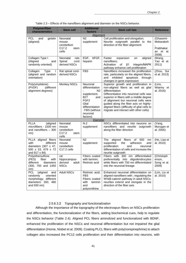
Chapter 2
41
Table 2.3 – Effects of the nanofibers alignment and diameter on the NSCs behavior.
Polymer/fiber characteristics
Stem cell Additional
factors Stem cell fate Reference
Alignment
PCL and gelatin (aligned)
Neonatal mouse cerebellum C17.2 stem cells
N2 supplement
Cell proliferation and elongation; Neurite outgrowth parallel to the direction of the fiber alignment
(Ghasemi-Mobarakeh, Prabhakaran et al. 2008)
Collagen Type I (Aligned and randomly oriented)
Neonatal rats Spinal cord derived NSCs
EGF, bFGF, heparin
Faster expansion on aligned nanofibers; Activation of β1 integrin/MAPK pathway enhance cell proliferation
(Wang, Yao et al. 2011)
Collagen Type I (aligned and random orientation)
Rat spinal cord-derived NSCs
FBS Nanofibers increased the proliferation rate, particularly on the aligned fibers, and inhibited apoptosis through changes in gene expression
(Zhou, Sui et al. 2013)
Poly(vinylidene) (PVDF) (different alignment degrees)
Monkey NSCs Neuronal differentiation: N2 supplement, B27 and FGF2 Glial differentiation: FBS (without neuronal factors)
Superior growth and proliferation in non-aligned fibers as well as glial differentiation Differentiation into neuronal cells was superior in fibers with a middle degree of alignment but neuronal cells were guided along the fiber axis on highly-aligned fibers (difficulty of glial cells to migrate and interact with other cells)
(Lins, Wianny et al. 2016)
Diameter
PLLA (aligned microfibers - 1500 nm and nanofibers – 300 nm)
Neonatal mouse cerebellum C17.2 stem cells
N-2 supplement
NSCs differentiated into neurons on nanofibers and neurite outgrowth along the fiber direction
(Yang, Murugan et al. 2005)
PLLA aligned fibers with different diameters (307 ± 47, 500 ± 53, 679 ± 72 and 917 ± 84)
Neonatal mouse cerebellum C17.2 cells
N2 supplement
The aligned fibers of 500 nm supported the adhesion and proliferation and neuronal differentiation of cells and increase the neurite outgrowth
(He, Liao et al. 2010)
Polyethersulfone (PES) fiber with different diameters (300, 750 and 1450 nm)
rat hippocampus-derived adult NSCs
Fibers coated with laminin; Retinoic acid
Fibers with 300 nm differentiated preferentially into oligodendrocytes while fibers with 750 nm differentiated into the neuronal lineage
(Christopherson, Song et al. 2009)
PCL (aligned and randomly oriented morphology; different diameters: 260, 480 and 930 nm)
Adult NSCs Retinoic acid; FBS Fibers coated with laminin and polyornithine
Enhanced neuronal differentiation on aligned nanofibers with ; regulating the Wnt/β-catenin pathway in adult NSCs; neurites extend and elongate in the direction of the fiber axis
(Lim, Liu et al. 2010)
Topography and functionalization
Although the importance of the topography of the electrospun fibers on NSCs proliferation
and differentiation, the functionalization of the fibers, adding biochemical cues, help to regulate
the NSCs behavior (Table 2.4). Aligned PCL fibers aminolized and functionalized with BDNF,
enhanced the proliferation of the NSCs and neuronal differentiation but not impaired the glial
differentiation (Horne, Nisbet et al. 2009). Coating PLCL fibers with poly(norepinephrine) to attach
collagen also increased the PC12 cells proliferation and their differentiation into neurons, with

Chapter 2
42
superior extension and number of neurites (Taskin, Xu et al. 2015). The immobilization of RE-1
silencing transcriptional factor (REST) small interference RNA (siRNA) (gene delivery vector) on
the PCL nanofibers surface via polydopamine coating, increased the NSCs differentiation into
functional neurons while reduced their differentiation into astrocytes, when compared to the PCL
film also immobilized with REST (Low, Rujitanaroj et al. 2013).
Similar to the electrospinning technique, the “spinneret based tunable engineered
parameters” (STEP) technology (use a metal micropipette and without an electrical field) was
used in the production of polystyrene nanofibers with aligned configuration (one layer) and
crosshatch (double layer) configuration (Bakhru, Nain et al. 2011). The scaffolds were
functionalized with poly-L-ornithine and laminin and NSCs were seeded on them. The cells
presented a polarized morphology and follow the alignment of the fibers, differentiating mainly
into neurons. However, cells were also seeded in a planar structure in close proximity to the cells
on the fibers. The cells on the planar structure were also differentiated into the neuronal lineage,
suggesting that a paracrine effect influenced the cells near to the ones on the fibers (Bakhru, Nain
et al. 2011).
However, neurotrophic factors such as BDNF can also be encapsulated in the electrospun
nanofibibers (from a copolymer of Ɛ-caprolactone and ethyl ethylene phosphate) (Low,
Rujitanaroj et al. 2013). The controlled release of BDNF associated with the topographical cues
of the scaffolds induced superior neuronal differentiation of mouse NSCs. The incorporation of
molecules such as retinoic acid and purmorphamine on the gelatin outer shell, on fibers with a
core-shell structure produced using co-axial electrospinning, enhanced the differentiation of
NSCs into motor neurons and improved the neurite extension (Binan, Tendey et al. 2014).
The own polymer used to construct the fibrous scaffolds also influenced the cell behavior.
The functional groups of collagen can interact with β1 integrin and activate MAPK signaling
cascade on the neonatal rat spinal cord derived NSCs, enhancing the cell proliferation (Wang,
Yao et al. 2011). Even without the aligned morphology, the fibrous scaffolds from chitosan were
a better choice for the NSCs proliferation and neuronal differentiation when compared to fibers
from either cellulose acetate or polyethersulfone (Du, Tan et al. 2014), reinforcing the importance
to choose the appropriate polymer to produce the electrospun mats for NSCs interaction.
Therefore, the combinatorial effects of nanostructure of the scaffolds and the biochemical
cues from the neurotrophic factors or other molecules are important in driving the NSPCs
behavior. Even with that, additional factors must be added to the culture medium to promote the
suitable cell maintenance (EGF, bFGF, FGF2) and to induce the neuronal (retinoic acid, N2
supplement) and the glial (FBS) differentiation.

Chapter 2
43
Table 2.4 – Effects of the nanofibers functionalization on the NSCs behavior.
Polymer/fiber characteristics
Stem cell Additional
factors Stem cell fate Reference
Surface Functionalization
PCL (3D non-woven scaffolds chemically modified with ethylamine – amine functionalization)
Adult rat brain-derived NSCs
FBS;
Increased the adhesion and spreading over all the scaffold NSCs differentiate primarily into oligodendrocytes in the presence of FBS
(Nisbet, Yu et al. 2008)
PCL (aligned vs random scaffolds aminolyzed and functionalized with BDNF)
Embryonic mice NSCs
EGF, FGF2 Enhance NSC proliferation; direct cell fate towards neuronal and oligodendrocyte specification
(Horne, Nisbet et al. 2009)
PCL nanofibers (immobilization with REST-siRNA)
Mice hippocampus-derived NSCs
N-2 supplement; B27; FGF2;
Improved the NSCs differentiation into functional neurons while reduced their differentiation into astrocytes
(Low, Rujitanaroj et al. 2013)
Polystyrene (highly aligned single and double layer crosshatch meshes – functionalized with poly-L-ornithine and laminin), STEP technology
Rat hippocampal NSCs
FGF2 Highly aligned fibers induced the neuronal NSCs differentiation and cellular polarization and elongation along the fiber alignment; NSCs on the fibers caused a paracrine signaling effect on near NSCs on planar surfaces, inducing their neuronal differentiation
(Bakhru, Nain et al. 2011)
Silica nanofibers (amino-functionalized with (3-aminoprpyl)trimethoxysilane)
Rat neural stem cells
N2 supplement, EGF, bFGF
Functionalized silica fibers improved the NSCs proliferation and neuronal maturation regarding PDL-coated flat substrates
(Chen, Hsieh et al. 2013)
Poly(lactic acid-co-caprolactone) (PLCL) (aligned and random orientation – coated with poly(norepinephrine) to attach collagen)
PC12 cells (derived from rat adrenal pheochromocytoma)
Attach collagen localize NGF from the culture medium
Cells proliferate and differentiate on the substrate and the alignment of neurites was verified on aligned topography with higher extension and neurites numbers
(Taskin, Xu et al. 2015)
Encapsulation of factors
Copolymer of Ɛ-caprolactone and ethyl ethylene phosphate electrospun fibers
Mouse NSCs Fibers loaded with BDNF and/or retinoic acid
Improved the differentiation of NSCs (Low, Rujitanaroj et al. 2013)
PLLA (core) and gelatin (shell) (co-electrospun fibers)
Engineered neural stem-like cells
Gelatin shell loaded with retinoic acid and purmorphamine
Cells proliferate and differentiate into motor neurons; enhanced neurite outgrowth of the resulting neurons
(Binan, Tendey et al. 2014)
Polymer choice
Chitosan, cellulose acetate and polyethersulfone electrospun fibers
PC12 cells and human NSC (from America Type Culture Collection)
B27, Leukemia inhibitory factor, fibers coated with collagen
Better NSCs proliferation ad neuronal differentiation in chitosan nanofibers
(Du, Tan et al. 2014)
Conductivity
Fibrous mats with conductive materials/polymers in their structure can provide electrical
stimulation to NSCs (Table 2.5). The conducting polymer polyaniline was used to dope the
electrospun nanofibers from PCL/gelatin blends (Ghasemi-Mobarakeh, Prabhakaran et al. 2009)
or it was blended with PLLA and the resulting solutions were electrospun into fibrous substrates
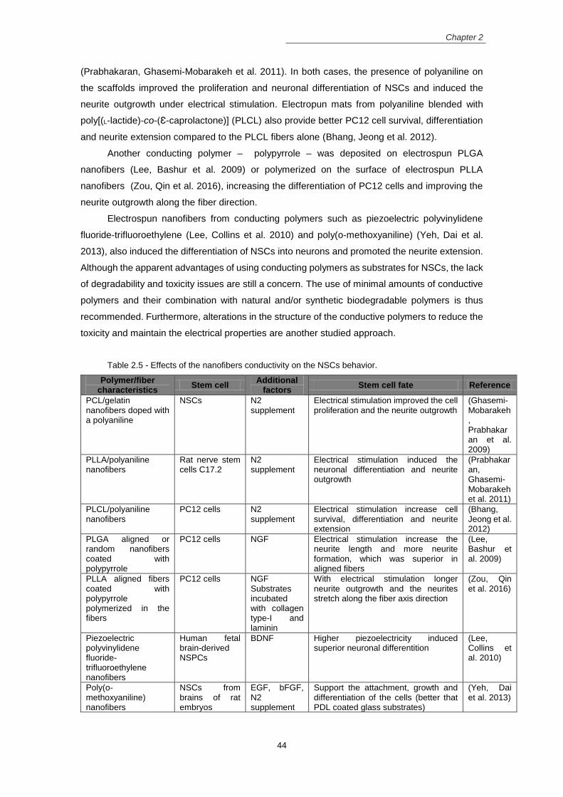
Chapter 2
44
(Prabhakaran, Ghasemi-Mobarakeh et al. 2011). In both cases, the presence of polyaniline on
the scaffolds improved the proliferation and neuronal differentiation of NSCs and induced the
neurite outgrowth under electrical stimulation. Electropun mats from polyaniline blended with
poly[(L-lactide)-co-(Ɛ-caprolactone)] (PLCL) also provide better PC12 cell survival, differentiation
and neurite extension compared to the PLCL fibers alone (Bhang, Jeong et al. 2012).
Another conducting polymer – polypyrrole – was deposited on electrospun PLGA
nanofibers (Lee, Bashur et al. 2009) or polymerized on the surface of electrospun PLLA
nanofibers (Zou, Qin et al. 2016), increasing the differentiation of PC12 cells and improving the
neurite outgrowth along the fiber direction.
Electrospun nanofibers from conducting polymers such as piezoelectric polyvinylidene
fluoride-trifluoroethylene (Lee, Collins et al. 2010) and poly(o-methoxyaniline) (Yeh, Dai et al.
2013), also induced the differentiation of NSCs into neurons and promoted the neurite extension.
Although the apparent advantages of using conducting polymers as substrates for NSCs, the lack
of degradability and toxicity issues are still a concern. The use of minimal amounts of conductive
polymers and their combination with natural and/or synthetic biodegradable polymers is thus
recommended. Furthermore, alterations in the structure of the conductive polymers to reduce the
toxicity and maintain the electrical properties are another studied approach.
Table 2.5 - Effects of the nanofibers conductivity on the NSCs behavior.
Polymer/fiber characteristics
Stem cell Additional
factors Stem cell fate Reference
PCL/gelatin nanofibers doped with a polyaniline
NSCs N2 supplement
Electrical stimulation improved the cell proliferation and the neurite outgrowth
(Ghasemi-Mobarakeh, Prabhakaran et al. 2009)
PLLA/polyaniline nanofibers
Rat nerve stem cells C17.2
N2 supplement
Electrical stimulation induced the neuronal differentiation and neurite outgrowth
(Prabhakaran, Ghasemi-Mobarakeh et al. 2011)
PLCL/polyaniline nanofibers
PC12 cells N2 supplement
Electrical stimulation increase cell survival, differentiation and neurite extension
(Bhang, Jeong et al. 2012)
PLGA aligned or random nanofibers coated with polypyrrole
PC12 cells NGF Electrical stimulation increase the neurite length and more neurite formation, which was superior in aligned fibers
(Lee, Bashur et al. 2009)
PLLA aligned fibers coated with polypyrrole polymerized in the fibers
PC12 cells NGF Substrates incubated with collagen type-I and laminin
With electrical stimulation longer neurite outgrowth and the neurites stretch along the fiber axis direction
(Zou, Qin et al. 2016)
Piezoelectric polyvinylidene fluoride-trifluoroethylene nanofibers
Human fetal brain-derived NSPCs
BDNF Higher piezoelectricity induced superior neuronal differentition
(Lee, Collins et al. 2010)
Poly(o-methoxyaniline) nanofibers
NSCs from brains of rat embryos
EGF, bFGF, N2 supplement
Support the attachment, growth and differentiation of the cells (better that PDL coated glass substrates)
(Yeh, Dai et al. 2013)

Chapter 2
45
2.6 References Abbasi, N., S. M. Hashemi, et al. (2015). "Influence of oriented nanofibrous PCL scaffolds on quantitative gene expression during neural differentiation of mouse embryonic stem cells." Journal of Biomedical Materials Research Part A 104(1): 155-164.
Akhavan, O. and E. Ghaderi (2013). "Differentiation of human neural stem cells into neural networks on graphene nanogrids." Journal of Materials Chemistry B 1(45): 6291-6301.
Akhavan, O., E. Ghaderi, et al. (2015). "Near infrared laser stimulation of human neural stem cells into neurons on graphene nanomesh semiconductors." Colloids and Surfaces B: Biointerfaces 126: 313-321.
Akhavan, O., E. Ghaderi, et al. (2016). "Rolled graphene oxide foams as three-dimensional scaffolds for growth of neural fibers using electrical stimulation of stem cells." Carbon 97: 71-77.
Alvarez-Mejia, L., J. Morales, et al. (2015). "Functional recovery in spinal cord injured rats using polypyrrole/iodine implants and treadmill training." Journal of Materials Science: Materials in Medicine 26(7):
1-11. Alves-Sampaio, A., C. García-Rama, et al. (2016). "Biofunctionalized PEDOT-coated microfibers for the treatment of spinal cord injury." Biomaterials 89: 98-113.
Anton, F. (1934). Process and apparatus for preparing artificial threads, Google Patents. Arulmoli, J., H. J. Wright, et al. (2016). "Combination scaffolds of salmon fibrin, hyaluronic acid, and laminin for human neural stem cell and vascular tissue engineering." Acta biomaterialia 43: 122-138.
Bagdi, K., K. Molná, et al. (2011). "Specific interactions, structure and properties in segmented polyurethane elastomers." eXPRESS Polym Lett 5: 417.
Bai, S., W. Zhang, et al. (2014). "Silk nanofiber hydrogels with tunable modulus to regulate nerve stem cell fate." Journal of Materials Chemistry B 2(38): 6590-6600.
Bakhru, S., A. S. Nain, et al. (2011). "Direct and cell signaling-based, geometry-induced neuronal differentiation of neural stem cells." Integrative Biology 3(12): 1207-1214.
Banerjee, A., M. Arha, et al. (2009). "The influence of hydrogel modulus on the proliferation and differentiation of encapsulated neural stem cells." Biomaterials 30(27): 4695-4699.
Béduer, A., C. Vieu, et al. (2012). "Engineering of adult human neural stem cells differentiation through surface micropatterning." Biomaterials 33(2): 504-514.
Benson, M. D., M. I. Romero, et al. (2005). "Ephrin-B3 is a myelin-based inhibitor of neurite outgrowth." Proceedings of the national academy of sciences of the United States of America 102(30): 10694-10699.
Bhang, S. H., S. I. Jeong, et al. (2012). "Electroactive Electrospun Polyaniline/Poly [(L‐lactide)‐co‐(ε‐caprolactone)] Fibers for Control of Neural Cell Function." Macromolecular bioscience 12(3): 402-411.
Bhardwaj, N. and S. C. Kundu (2010). "Electrospinning: a fascinating fiber fabrication technique." Biotechnology Advances 28(3): 325-347.
Binan, L., C. Tendey, et al. (2014). "Differentiation of neuronal stem cells into motor neurons using electrospun poly-l-lactic acid/gelatin scaffold." Biomaterials 35(2): 664-674.
Blesch, A. and M. H. Tuszynski (2009). "Spinal cord injury: plasticity, regeneration and the challenge of translational drug development." Trends in neurosciences 32(1): 41-47.
Bond, A. M., G.-l. Ming, et al. (2015). "Adult mammalian neural stem cells and neurogenesis: five decades later." Cell stem cell 17(4): 385-395.
Bonner, J. F. and O. Steward (2015). "Repair of spinal cord injury with neuronal relays: From fetal grafts to neural stem cells." Brain research 1619: 115-123.
Bozkurt, G., A. J. Mothe, et al. (2010). "Chitosan channels containing spinal cord-derived stem/progenitor cells for repair of subacute spinal cord injury in the rat." Neurosurgery 67(6): 1733-1744.
Bradbury, E. J., L. D. Moon, et al. (2002). "Chondroitinase ABC promotes functional recovery after spinal cord injury." Nature 416(6881): 636-640.

Chapter 2
46
Brännvall, K., K. Bergman, et al. (2007). "Enhanced neuronal differentiation in a three‐dimensional collagen‐hyaluronan matrix." Journal of neuroscience research 85(10): 2138-2146.
Braughler, J. M. and E. D. Hall (1989). "Central nervous systems trauma and stroke: I. Biochemical considerations for oxygen radical formation and lipid peroxidation." Free Radical Biology and Medicine 6(3):
289-301. Caprini, A., D. Silva, et al. (2013). "A Novel Bioactive Peptide: Assessing its Activity Over Murine Neural Stem Cells and its Potential for Neural Tissue Engineering." New biotechnology. Carlberg, B., M. Z. Axell, et al. (2009). "Electrospun polyurethane scaffolds for proliferation and neuronal differentiation of human embryonic stem cells." Biomedical Materials 4(4): 045004.
Casper, C. L., J. S. Stephens, et al. (2004). "Controlling surface morphology of electrospun polystyrene fibers: effect of humidity and molecular weight in the electrospinning process." Macromolecules 37(2): 573-
578. Chan-Chan, L., R. Solis-Correa, et al. (2010). "Degradation studies on segmented polyurethanes prepared with HMDI, PCL and different chain extenders." Acta Biomaterialia 6(6): 2035-2044.
Chan-Chan, L., C. Tkaczyk, et al. (2013). "Characterization and biocompatibility studies of new degradable poly (urea) urethanes prepared with arginine, glycine or aspartic acid as chain extenders." Journal of Materials Science: Materials in Medicine 24(7): 1733-1744.
Chen, G., Y.-r. Hu, et al. (2010). "Functional recovery following traumatic spinal cord injury mediated by a unique polymer scaffold seeded with neural stem cells and Schwann cells." Chinese Medical Journal (English Edition) 123(17): 2424.
Chen, W. and Y. W. Tong (2012). "PHBV microspheres as neural tissue engineering scaffold support neuronal cell growth and axon–dendrite polarization." Acta Biomaterialia 8(2): 540-548.
Chen, W. S., P. H. Hsieh, et al. (2013). "Chemically modified electrospun silica nanofibers for promoting growth and differentiation of neural stem cells." Journal of Materials Chemistry B 9: 1205-1215. Chen, Y.-W., S.-H. Chiou, et al. (2006). Using gelatin scaffold with coated basic fibroblast growth factor as a transfer system for transplantation of human neural stem cells. Transplantation proceedings, Elsevier 38(5): 1616-1617.
Cheng, H., Y.-C. Huang, et al. (2007). "Laminin-incorporated nerve conduits made by plasma treatment for repairing spinal cord injury." Biochemical and biophysical research communications 357(4): 938-944.
Cherry, J., A. Carlson, et al. (2012). "Oriented, Multimeric Biointerfaces of the L1 Cell Adhesion Molecule: An Approach to Enhance Neuronal and Neural Stem Cell Functions on 2-D and 3-D Polymer Substrates." Biointerphases 7(1-4): 1-16.
Cholas, R. H., H.-P. Hsu, et al. (2012). "The reparative response to cross-linked collagen-based scaffolds in a rat spinal cord gap model." Biomaterials 33(7): 2050-2059.
Chow, W. N., D. G. Simpson, et al. (2007). "Evaluating neuronal and glial growth on electrospun polarized matrices: bridging the gap in percussive spinal cord injuries." Neuron glia biology 3(02): 119-126.
Christopherson, G. T., H. Song, et al. (2009). "The influence of fiber diameter of electrospun substrates on neural stem cell differentiation and proliferation." Biomaterials 30(4): 556-564.
Colello, R. J., W. N. Chow, et al. (2016). "The incorporation of growth factor and chondroitinase ABC into an electrospun scaffold to promote axon regrowth following spinal cord injury." Journal of tissue engineering and regenerative medicine 10(8): 656-668.
Colombo, G., M. Wirz, et al. (2001). "Driven gait orthosis for improvement of locomotor training in paraplegic patients." Spinal Cord 39(5): 252-255.
Corey, J. M., C. C. Gertz, et al. (2008). "The design of electrospun PLLA nanofiber scaffolds compatible with serum-free growth of primary motor and sensory neurons." Acta biomaterialia 4(4): 863-875.
Costa, L. M., J. E. Pereira, et al. (2013). "Rolipram promotes functional recovery after contusive thoracic spinal cord injury in rats." Behavioural brain research 243: 66-73.

Chapter 2
47
Cruz, G. J., R. Mondragón-Lozano, et al. (2012). "Plasma polypyrrole implants recover motor function in rats after spinal cord transection." Journal of Materials Science: Materials in Medicine 23(10): 2583-2592.
De Vrieze, S., T. Van Camp, et al. (2009). "The effect of temperature and humidity on electrospinning." Journal of materials science 44(5): 1357-1362.
Delgado-Rivera, R., S. L. Harris, et al. (2009). "Increased FGF-2 secretion and ability to support neurite outgrowth by astrocytes cultured on polyamide nanofibrillar matrices." Matrix Biology 28(3): 137-147.
Dinan, B., N. Bhattarai, et al. "Characterization of Chitosan Based Hybrid Nanofiber Scaffolds for Tissue Engineering." Journal of Undergraduate Research in Bioengineering: 33-37. Du, B. L., X. Zeng, et al. (2015). "Graft of the gelatin sponge scaffold containing genetically‐modified neural
stem cells promotes cell differentiation, axon regeneration, and functional recovery in rat with spinal cord transection." Journal of Biomedical Materials Research Part A 103(4): 1533-1545.
Du, J., E. Tan, et al. (2014). "Comparative evaluation of chitosan, cellulose acetate, and polyethersulfone nanofiber scaffolds for neural differentiation." Carbohydrate polymers 99: 483-490.
Dubendorf, P. (1999). "Spinal cord injury pathophysiology." Critical care nursing quarterly 22(2): 31-35.
Duncan, I. and R. Hoffman (1997). "Schwann cell invasion of the central nervous system of the myelin mutants." Journal of anatomy 190(1): 35-49.
Dusart, I. and M. Schwab (1994). "Secondary cell death and the inflammatory reaction after dorsal hemisection of the rat spinal cord." European Journal of Neuroscience 6(5): 712-724.
Ellis-Behnke, R., Y. Liang, et al. (2009). "Forever young: how to control the elongation, differentiation, and proliferation of cells using nanotechnology." Cell transplantation 18(9): 1047-1058.
Fabbro, A., A. Villari, et al. (2012). "Spinal cord explants use carbon nanotube interfaces to enhance neurite outgrowth and to fortify synaptic inputs." ACS nano 6(3): 2041-2055.
Faden, A. I. (1990). "Opioid and nonopioid mechanisms may contribute to dynorphin's pathophysiological actions in spinal cord injury." Annals of neurology 27(1): 67-74.
Fan, C., X. Li, et al. (2017). "A modified collagen scaffold facilitates endogenous neurogenesis for acute spinal cord injury repair." Acta Biomaterialia 15(51): 304-316.
Fan, J., H. Zhang, et al. (2011). "Neural regrowth induced by PLGA nerve conduits and neurotrophin‐3 in
rats with complete spinal cord transection." Journal of Biomedical Materials Research Part B: Applied Biomaterials 97(2): 271-277.
Fehlings, M., H. Nakashima, et al. (2016). "Rationale, design and critical end points for the Riluzole in Acute Spinal Cord Injury Study (RISCIS): a randomized, double-blinded, placebo-controlled parallel multi-center trial." Spinal Cord 54(1): 8-15.
Fehlings, M. G., N. Theodore, et al. (2011). "A phase I/IIa clinical trial of a recombinant Rho protein antagonist in acute spinal cord injury." Journal of neurotrauma 28(5): 787-796.
Fu, H.-L., Y. Hong, et al. (2014). "Collagenase-labile polyurethane urea synthesis and processing into hollow fiber membranes." Biomacromolecules 15(8): 2924-2932.
Gao, M., H. Tao, et al. (2017). "Functionalized self-assembly polypeptide hydrogel scaffold applied in modulation of neural progenitor cell behavior." Journal of Bioactive and Compatible Polymers 32(1): 45-60.
Geisel, N., J. Clasohm, et al. (2016). "Microstructured Multilevel Bacterial Cellulose Allows the Guided Growth of Neural Stem Cells." Small 12(39): 5407-5413.
Gertz, C. C., M. K. Leach, et al. (2010). "Accelerated neuritogenesis and maturation of primary spinal motor neurons in response to nanofibers." Developmental Neurobiology 70(8): 589-603.
Ghasemi-Mobarakeh, L., M. P. Prabhakaran, et al. (2008). "Electrospun poly(ɛ-caprolactone)/gelatin nanofibrous scaffolds for nerve tissue engineering." Biomaterials 29(34): 4532-4539.

Chapter 2
48
Ghasemi-Mobarakeh, L., M. P. Prabhakaran, et al. (2009). "Electrical stimulation of nerve cells using conductive nanofibrous scaffolds for nerve tissue engineering." Tissue Engineering Part A 15(11): 3605-
3619. Ghosh, A., F. Haiss, et al. (2009). "Rewiring of hindlimb corticospinal neurons after spinal cord injury." Nature neuroscience 13(1): 97-104.
Gjorevski, N. and C. M. Nelson (2009). "Bidirectional extracellular matrix signaling during tissue morphogenesis." Cytokine & growth factor reviews 20(5): 459-465.
Goldsmith, H. S., A. Fonseca, et al. (2005). "Spinal cord separation: MRI evidence of healing after omentum–collagen reconstruction." Neurological research 27(2): 115-123.
GrandPré, T., F. Nakamura, et al. (2000). "Identification of the Nogo inhibitor of axon regeneration as a Reticulon protein." Nature 403(6768): 439-444.
Guelcher, S. A. (2008). "Biodegradable polyurethanes: synthesis and applications in regenerative medicine." Tissue Engineering Part B: Reviews 14(1): 3-17.
Guo, J., H. Su, et al. (2007). "Reknitting the injured spinal cord by self-assembling peptide nanofiber scaffold." Nanomedicine: Nanotechnology, Biology and Medicine 3(4): 311-321.
Hayes, K., A. Blight, et al. (1993). "Preclinical trial of 4-aminopyridine in patients with chronic spinal cord injury." Spinal Cord 31(4): 216-224.
He, J., X.-M. Wang, et al. (2012). "Scaffolds for central nervous system tissue engineering." Frontiers of Materials Science 6(1): 1-25.
He, L., S. Liao, et al. (2010). "Synergistic effects of electrospun PLLA fiber dimension and pattern on neonatal mouse cerebellum C17. 2 stem cells." Acta Biomaterialia 6(8): 2960-2969.
Henriques, C., R. Vidinha, et al. (2009). "A systematic study of solution and processing parameters on nanofiber morphology using a new electrospinning apparatus." Journal of nanoscience and nanotechnology 9(6): 3535-3545.
Horne, M. K., D. R. Nisbet, et al. (2009). "Three-dimensional nanofibrous scaffolds incorporating immobilized BDNF promote proliferation and differentiation of cortical neural stem cells." Stem cells and development 19(6): 843-852.
Hsieh, F.-Y., H.-H. Lin, et al. (2015). "3D bioprinting of neural stem cell-laden thermoresponsive biodegradable polyurethane hydrogel and potential in central nervous system repair." Biomaterials 71: 48-
57. Hulsebosch, C. E. (2002). "Recent advances in pathophysiology and treatment of spinal cord injury." Advances in physiology education 26(4): 238-255.
Hurtado, A., J. M. Cregg, et al. (2011). "Robust CNS regeneration after complete spinal cord transection using aligned poly-l-lactic acid microfibers." Biomaterials 32(26): 6068-6079.
Hyun, J. K. and H. W. Kim (2010). "Clinical and experimental advances in regeneration of spinal cord injury." Journal of tissue engineering 1(1): 650857.
Imani, S., Z. Zagari, et al. (2016). "Functional Recovery of Carbon Nanotube/Nafion Nanocomposite in Rat Model of Spinal Cord Injury." Artificial cells, nanomedicine, and biotechnology 44(1): 144-149.
Iwasaki, M., J. T. Wilcox, et al. (2014). "Synergistic effects of self-assembling peptide and neural stem/progenitor cells to promote tissue repair and forelimb functional recovery in cervical spinal cord injury." Biomaterials 35(9): 2617-2629.
Iyer, N. R., T. S. Wilems, et al. (2017). "Stem cells for spinal cord injury: Strategies to inform differentiation and transplantation." Biotechnology and bioengineering 114(2): 245-259.
Jain, A., Y. T. Kim, et al. (2006). "In situ gelling hydrogels for conformal repair of spinal cord defects, and local delivery of BDNF after spinal cord injury." Biomaterials 27(3): 497-504.
James, N. D., J. Shea, et al. (2015). "Chondroitinase gene therapy improves upper limb function following cervical contusion injury." Experimental neurology 271: 131-135.

Chapter 2
49
Jan, E. and N. A. Kotov (2007). "Successful differentiation of mouse neural stem cells on layer-by-layer assembled single-walled carbon nanotube composite." Nano letters 7(5): 1123-1128.
Kabu, S., Y. Gao, et al. (2015). "Drug delivery, cell-based therapies, and tissue engineering approaches for spinal cord injury." Journal of Controlled Release 219: 141-154.
Kai, D., G. Jin, et al. (2013). "Electrospun synthetic and natural nanofibers for regenerative medicine and stem cells." Biotechnology Journal 8(1): 59-72.
Kam, N. W. S., E. Jan, et al. (2008). "Electrical stimulation of neural stem cells mediated by humanized carbon nanotube composite made with extracellular matrix protein." Nano Letters 9(1): 273-278.
Kaneko, A., A. Matsushita, et al. (2015). "A 3D nanofibrous hydrogel and collagen sponge scaffold promotes locomotor functional recovery, spinal repair, and neuronal regeneration after complete transection of the spinal cord in adult rats." Biomedical Materials 10(1): 015008.
Keung, A. J., E. M. de Juan‐Pardo, et al. (2011). "Rho GTPases mediate the mechanosensitive lineage commitment of neural stem cells." Stem Cells 29(11): 1886-1897.
Khil, M. S., D. I. Cha, et al. (2003). "Electrospun nanofibrous polyurethane membrane as wound dressing." Journal of Biomedical Materials Research Part B: Applied Biomaterials 67(2): 675-679.
Kidoaki, S., I. K. Kwon, et al. (2006). "Structural features and mechanical properties of in situ–bonded meshes of segmented polyurethane electrospun from mixed solvents." Journal of Biomedical Materials Research Part B: Applied Biomaterials 76(1): 219-229.
King, V. R., A. Alovskaya, et al. (2010). "The use of injectable forms of fibrin and fibronectin to support axonal ingrowth after spinal cord injury." Biomaterials 31(15): 4447-4456.
King, V. R., W. L. Huang, et al. (2006). "Omega-3 fatty acids improve recovery, whereas omega-6 fatty acids worsen outcome, after spinal cord injury in the adult rat." The Journal of neuroscience 26(17): 4672-4680.
Koutsopoulos, S. and S. Zhang (2013). "Long-term three-dimensional neural tissue cultures in functionalized self-assembling peptide hydrogels, matrigel and collagen I." Acta biomaterialia 9(2): 5162-5169.
Kubinová, Š., D. Horak, et al. (2011). "Highly superporous cholesterol‐modified poly (2‐hydroxyethyl methacrylate) scaffolds for spinal cord injury repair." Journal of Biomedical Materials Research Part A 99(4):
618-629. Kubinová, Š. and E. Syková (2012). "Biomaterials combined with cell therapy for treatment of spinal cord injury." Regenerative medicine 7(2): 207-224.
Kueh, J. L.-L., D. Li, et al. (2012). "Directionality and bipolarity of olfactory ensheathing cells on electrospun nanofibers." Nanomedicine 7(8): 1211-1224.
Kwon, B. K., E. Okon, et al. (2011). "A systematic review of non-invasive pharmacologic neuroprotective treatments for acute spinal cord injury." Journal of neurotrauma 28(8): 1545-1588.
Lai, B.-Q., J.-M. Wang, et al. (2013). "The integration of NSC-derived and host neural networks after rat spinal cord transection." Biomaterials. Lai, B.-Q., J.-M. Wang, et al. (2013). "Graft of a tissue-engineered neural scaffold serves as a promising strategy to restore myelination after rat spinal cord transection." Stem cells and development 23(8): 910-
921. Lam, H. J., S. Patel, et al. (2010). "In vitro regulation of neural differentiation and axon growth by growth factors and bioactive nanofibers." Tissue Engineering Part A 16(8): 2641-2648.
Lee, J. Y., C. A. Bashur, et al. (2009). "Polypyrrole-coated electrospun PLGA nanofibers for neural tissue applications." Biomaterials 30(26): 4325-4335.
Lee, Y.-S., G. Collins, et al. (2010). Neural differentiation of human neural stem/progenitor cells on piezoelectric scaffolds. Bioengineering Conference, Proceedings of the 2010 IEEE 36th Annual Northeast, IEEE.

Chapter 2
50
Lee, Y. B., S. Polio, et al. (2010). "Bio-printing of collagen and VEGF-releasing fibrin gel scaffolds for neural stem cell culture." Experimental neurology 223(2): 645.
Leipzig, N. D. and M. S. Shoichet (2009). "The effect of substrate stiffness on adult neural stem cell behavior." Biomaterials 30(36): 6867-6878.
Leipzig, N. D., R. G. Wylie, et al. (2011). "Differentiation of neural stem cells in three-dimensional growth factor-immobilized chitosan hydrogel scaffolds." Biomaterials 32(1): 57-64.
Lewicka, M., O. Hermanson, et al. (2012). "Recombinant spider silk matrices for neural stem cell cultures." Biomaterials 33(31): 7712-7717.
Li, G., D. Li, et al. (2013). "Alternating block polyurethanes based on PCL and PEG as potential nerve regeneration materials." Journal of Biomedical Materials Research Part A 102(3): 685-697.
Li, H., A. Wijekoon, et al. (2013). "Encapsulated Neural Stem Cell Neuronal Differentiation in Fluorinated Methacrylamide Chitosan Hydrogels." Annals of biomedical engineering 42(7): 1456-1469.
Li, N., Q. Zhang, et al. (2013). "Three-dimensional graphene foam as a biocompatible and conductive scaffold for neural stem cells." Scientific reports 3: 1604.
Li, X., S. Liu, et al. (2016). "Training Neural Stem Cells on Functional Collagen Scaffolds for Severe Spinal Cord Injury Repair." Advanced Functional Materials 26(32): 5835-5847.
Li, X., Z. Xiao, et al. (2013). "Promotion of neuronal differentiation of neural progenitor cells by using EGFR antibody functionalized collagen scaffolds for spinal cord injury repair." Biomaterials 34(21): 5107-5116.
Liebscher, T., L. Schnell, et al. (2005). "Nogo‐A antibody improves regeneration and locomotion of spinal cord–injured rats." Annals of neurology 58(5): 706-719.
Liedmann, A., S. Frech, et al. (2012). "Differentiation of Human Neural Progenitor Cells in Functionalized Hydrogel Matrices." BioResearch Open Access 1(1): 16-24.
Lim, S. H., X. Y. Liu, et al. (2010). "The effect of nanofiber-guided cell alignment on the preferential differentiation of neural stem cells." Biomaterials 31(34): 9031-9039.
Lim, S. H. and H.-Q. Mao (2009). "Electrospun scaffolds for stem cell engineering." Advanced drug delivery reviews 61(12): 1084-1096.
Lins, L. C., F. Wianny, et al. (2016). "Effect of polyvinylidene fluoride electrospun fiber orientation on neural stem cell differentiation." Journal of Biomedical Materials Research Part B: Applied Biomaterials 105(8):
2376-2393. Liu, T., J. D. Houle, et al. (2012). "Nanofibrous collagen nerve conduits for spinal cord repair." Tissue Engineering Part A 18(9-10): 1057-1066.
Liu, T., J. Xu, et al. (2012). "Sustained release of neurotrophin‐3 and chondroitinase ABC from electrospun
collagen nanofiber scaffold for spinal cord injury repair." Journal of Biomedical Materials Research Part A 100(1): 236-242.
Löw, K., M. Culbertson, et al. (2008). "Netrin-1 is a novel myelin-associated inhibitor to axon growth." The Journal of neuroscience 28(5): 1099-1108.
Low, W. C., P.-O. Rujitanaroj, et al. (2013). "Nanofibrous scaffold-mediated REST knockdown to enhance neuronal differentiation of stem cells." Biomaterials 34(14): 3581-3590.
Low, W. C., P.-O. Rujitanaroj, et al. (2013). "Nanofiber-mediated release of retinoic acid and brain-derived neurotrophic factor for enhanced neuronal differentiation of neural progenitor cells." Drug delivery and translational research 5(2): 89-100.
Lu, P., G. Woodruff, et al. (2014). "Long-distance axonal growth from human induced pluripotent stem cells after spinal cord injury." Neuron 83(4): 789-796.
Luo, C., M. Nangrejo, et al. (2010). "A novel method of selecting solvents for polymer electrospinning." Polymer 51(7): 1654-1662.

Chapter 2
51
Lutolf, M. and J. Hubbell (2005). "Synthetic biomaterials as instructive extracellular microenvironments for morphogenesis in tissue engineering." Nature biotechnology 23(1): 47-55.
Ma, W., W. Fitzgerald, et al. (2004). "CNS stem and progenitor cell differentiation into functional neuronal circuits in three-dimensional collagen gels." Experimental neurology 190(2): 276-288.
Ma, Z., Y. Hong, et al. (2011). "Biodegradable polyurethane ureas with variable polyester or polycarbonate soft segments: effects of crystallinity, molecular weight, and composition on mechanical properties." Biomacromolecules 12(9): 3265-3274.
Madigan, N. N., S. McMahon, et al. (2009). "Current tissue engineering and novel therapeutic approaches to axonal regeneration following spinal cord injury using polymer scaffolds." Respiratory physiology & neurobiology 169(2): 183-199.
Mahairaki, V., S. H. Lim, et al. (2010). "Nanofiber matrices promote the neuronal differentiation of human embryonic stem cell-derived neural precursors in vitro." Tissue Engineering Part A 17(5-6): 855-863.
Mahoney, M. J. and K. S. Anseth (2006). "Three-dimensional growth and function of neural tissue in degradable polyethylene glycol hydrogels." Biomaterials 27(10): 2265-2274.
Marcos-Fernández, A., G. A. Abraham, et al. (2006). "Synthesis and characterization of biodegradable non-toxic poly (ester-urethane-urea) s based on poly (ε-caprolactone) and amino acid derivatives." Polymer 47(3): 785-798.
McDonald, J. W. and C. Sadowsky (2002). "Spinal-cord injury." The Lancet 359(9304): 417-425.
McMurray, R. J., M. J. Dalby, et al. (2014). "Using biomaterials to study stem cell mechanotransduction, growth and differentiation." Journal of tissue engineering and regenerative medicine. Meiners, S., I. Ahmed, et al. (2007). "Engineering electrospun nanofibrillar surfaces for spinal cord repair: a discussion." Polymer International 56(11): 1340-1348.
Milbreta, U., L. H. Nguyen, et al. (2016). "Three-dimensional nanofiber hybrid scaffold directs and enhances axonal regeneration after spinal cord injury." ACS Biomaterials Science & Engineering 2(8): 1319-1329.
Mohtaram, N. K., J. Ko, et al. (2014). "Electrospun biomaterial scaffolds with varied topographies for neuronal differentiation of human‐induced pluripotent stem cells." Journal of Biomedical Materials Research Part A 103(8): 2591-2601.
Moreau-Fauvarque, C., A. Kumanogoh, et al. (2003). "The transmembrane semaphorin Sema4D/CD100, an inhibitor of axonal growth, is expressed on oligodendrocytes and upregulated after CNS lesion." The Journal of neuroscience 23(27): 9229-9239.
Mothe, A. J., I. Kulbatski, et al. (2008). "Adult spinal cord stem/progenitor cells transplanted as neurospheres preferentially differentiate into oligodendrocytes in the adult rat spinal cord." Cell Transplantation 17(7): 735-
751. Mothe, A. J., R. Y. Tam, et al. (2013). "Repair of the injured spinal cord by transplantation of neural stem cells in a hyaluronan-based hydrogel." Biomaterials 34(15): 3775-3783.
Mothe, A. J. and C. H. Tator (2013). "Review of transplantation of neural stem/progenitor cells for spinal cord injury." International Journal of Developmental Neuroscience 31(7): 701-713.
Murugan, R. and S. Ramakrishna (2007). "Design strategies of tissue engineering scaffolds with controlled fiber orientation." Tissue engineering 13(8): 1845-1866.
Nguyen, L. H., M. Gao, et al. (2017). "Three-dimensional aligned nanofibers-hydrogel scaffold for controlled non-viral drug/gene delivery to direct axon regeneration in spinal cord injury treatment." Scientific Reports 7
42212. Niederöst, B. P., D. R. Zimmermann, et al. (1999). "Bovine CNS myelin contains neurite growth-inhibitory activity associated with chondroitin sulfate proteoglycans." The Journal of neuroscience 19(20): 8979-8989.
Nikulina, E., J. L. Tidwell, et al. (2004). "The phosphodiesterase inhibitor rolipram delivered after a spinal cord lesion promotes axonal regeneration and functional recovery." Proceedings of the National Academy of Sciences of the United States of America 101(23): 8786-8790.

Chapter 2
52
Nisbet, D., J. Forsythe, et al. (2009). "Review paper: a review of the cellular response on electrospun nanofibers for tissue engineering." Journal of biomaterials applications 24(1): 7-29.
Nisbet, D., D. Moses, et al. (2009). "Enhancing neurite outgrowth from primary neurones and neural stem cells using thermoresponsive hydrogel scaffolds for the repair of spinal cord injury." Journal of Biomedical Materials Research Part A 89(1): 24-35.
Nisbet, D., L. Yu, et al. (2008). "Characterization of neural stem cells on electrospun poly (ε-caprolactone) submicron scaffolds: evaluating their potential in neural tissue engineering." Journal of Biomaterials Science, Polymer Edition 19(5): 623-634.
Nomura, H., C. H. Tator, et al. (2006). "Bioengineered strategies for spinal cord repair." Journal of neurotrauma 23(3-4): 496-507.
Olayo, R., C. Ríos, et al. (2008). "Tissue spinal cord response in rats after implants of polypyrrole and polyethylene glycol obtained by plasma." Journal of Materials Science: Materials in Medicine 19(2): 817-
826. Olson, H. E., G. E. Rooney, et al. (2009). "Neural Stem Cell–and Schwann Cell–Loaded Biodegradable Polymer Scaffolds Support Axonal Regeneration in the Transected Spinal Cord." Tissue Engineering Part A 15(7): 1797-1805.
Oprea, S. (2010). "The effect of chain extenders structure on properties of new polyurethane elastomers." Polymer bulletin 65(8): 753-766.
Ostrakhovitch, E., J. Byers, et al. (2012). "Directed differentiation of embryonic P19 cells and neural stem cells into neural lineage on conducting PEDOT-PEG and ITO glass substrates." Archives of Biochemistry and Biophysics 528(1): 21-31.
Pan, L., Y. Ren, et al. (2009). "Viability and differentiation of neural precursors on hyaluronic acid hydrogel scaffold." Journal of neuroscience research 87(14): 3207-3220.
Park, E., A. A. Velumian, et al. (2004). "The role of excitotoxicity in secondary mechanisms of spinal cord injury: a review with an emphasis on the implications for white matter degeneration." Journal of neurotrauma 21(6): 754-774.
Park, H.-s., M.-S. Gong, et al. (2013). "Catalyst-free synthesis of high elongation degradable polyurethanes containing varying ratios of isosorbide and polycaprolactone: physical properties and biocompatibility." Journal of Materials Science: Materials in Medicine 24(2): 281-294.
Patist, C. M., M. B. Mulder, et al. (2004). "Freeze-dried poly (D, L-lactic acid) macroporous guidance scaffolds impregnated with brain-derived neurotrophic factor in the transected adult rat thoracic spinal cord." Biomaterials 25(9): 1569-1582.
Perales-Alcacio, J., J. Santa-Olalla Tapia, et al. (2013). "HUVEC biocompatibility and platelet activation of segmented polyurethanes prepared with either glutathione or its amino acids as chain extenders." Journal of Biomaterials Science, Polymer Edition 24(14): 1601-1617.
Pertici, V., T. Trimaille, et al. (2014). "Repair of the injured spinal cord by implantation of a synthetic degradable block copolymer in rat." Biomaterials 35(24): 6248-6258.
Pham, Q. P., U. Sharma, et al. (2006). "Electrospinning of polymeric nanofibers for tissue engineering applications: a review." Tissue engineering 12(5): 1197-1211.
Piantino, J., J. Burdick, et al. (2006). "An injectable, biodegradable hydrogel for trophic factor delivery enhances axonal rewiring and improves performance after spinal cord injury." Experimental neurology 201(2): 359-367.
Potter, W., R. E. Kalil, et al. (2008). "Biomimetic material systems for neural progenitor cell-based therapy." Frontiers in bioscience: a journal and virtual library 13: 806.
Prabhakaran, M. P., L. Ghasemi-Mobarakeh, et al. (2011). "Electrospun conducting polymer nanofibers and electrical stimulation of nerve stem cells." Journal of bioscience and bioengineering 112(5): 501-507.
Pritchard, C. D., J. R. Slotkin, et al. (2010). "Establishing a model spinal cord injury in the African green monkey for the preclinical evaluation of biodegradable polymer scaffolds seeded with human neural stem cells." Journal of neuroscience methods 188(2): 258-269.

Chapter 2
53
Purcell, E. K., Y. Naim, et al. (2012). "Combining Topographical and Genetic Cues to Promote Neuronal Fate Specification in Stem Cells." Biomacromolecules 13(11): 3427-3438.
Puschmann, T. B., Y. de Pablo, et al. (2014). "A Novel Method for Three-Dimensional Culture of Central Nervous System Neurons." Tissue Engineering Part C: Methods 20(6): 485-492.
Qi, L., N. Li, et al. (2013). "The effects of topographical patterns and sizes on neural stem cell behavior." PLoS ONE 8(3): e59022.
Qu, J., D. Wang, et al. (2013). "Electrospun silk fibroin nanofibers in different diameters support neurite outgrowth and promote astrocyte migration." Journal of Biomedical Materials Research Part A 101(9): 2267-
2278. Ragnarsson, K. (2007). "Functional electrical stimulation after spinal cord injury: current use, therapeutic effects and future directions." Spinal Cord 46(4): 255-274.
Raineteau, O. and M. E. Schwab (2001). "Plasticity of motor systems after incomplete spinal cord injury." Nature Reviews Neuroscience 2(4): 263-273.
Raspa, A., R. Pugliese, et al. (2016). "Recent therapeutic approaches for spinal cord injury." Biotechnology and bioengineering 113(2): 253-259.
Ren, Y. J., Z. Y. Zhou, et al. (2009). "Preparation and characterization of fibroin/hyaluronic acid composite scaffold." International journal of biological macromolecules 44(4): 372-378.
Rim, N. G., C. S. Shin, et al. (2013). "Current approaches to electrospun nanofibers for tissue engineering." Biomedical Materials 8(1): 014102.
Ritfeld, G. J., B. M. Rauck, et al. (2014). "The effect of a polyurethane-based reverse thermal gel on bone marrow stromal cell transplant survival and spinal cord repair." Biomaterials 35(6): 1924-1931.
Roman, J. A., T. L. Niedzielko, et al. (2011). "Single-walled carbon nanotubes chemically functionalized with polyethylene glycol promote tissue repair in a rat model of spinal cord injury." Journal of neurotrauma 28(11):
2349-2362. Romanyuk, N., T. Amemori, et al. (2015). "Beneficial effect of human induced pluripotent stem cell-derived neural precursors in spinal cord injury repair." Cell transplantation 24(9): 1781-1797.
Rossignol, S. and A. Frigon (2011). "Recovery of locomotion after spinal cord injury: some facts and mechanisms." Annual review of neuroscience 34: 413-440.
Ruschel, J., F. Hellal, et al. (2015). "Systemic administration of epothilone B promotes axon regeneration after spinal cord injury." Science 348(6232): 347-352.
Sabelström, H., M. Stenudd, et al. (2014). "Neural stem cells in the adult spinal cord." Experimental neurology 260: 44-49.
Sabelström, H., M. Stenudd, et al. (2013). "Resident neural stem cells restrict tissue damage and neuronal loss after spinal cord injury in mice." Science 342(6158): 637-640.
Sadosky, A., B. Parsons, et al. (2016). "Pain relief and functional improvement in patients with neuropathic pain associated with spinal cord injury: an exploratory analysis of pregabalin clinical trials." Journal of Pain Research 9: 405-416.
Saglam, A., A. Perets, et al. (2013). "Angioneural crosstalk in scaffolds with oriented microchannels for regenerative spinal cord injury repair." Journal of Molecular Neuroscience 49(2): 334-346.
Samadikuchaksaraei, A. (2007). "An overview of tissue engineering approaches for management of spinal cord injuries." Journal of neuroengineering and rehabilitation 4: 15.
Santerre, J., K. Woodhouse, et al. (2005). "Understanding the biodegradation of polyurethanes: from classical implants to tissue engineering materials." Biomaterials 26(35): 7457-7470.
Schubert, M. A., M. J. Wiggins, et al. (1995). "Oxidative biodegradation mechanisms of biaxially strained poly (etherurethane urea) elastomers." Journal of biomedical materials research 29(3): 337-347.

Chapter 2
54
Shah, S., P. T. Yin, et al. (2014). "Guiding Stem Cell Differentiation into Oligodendrocytes Using Graphene‐Nanofiber Hybrid Scaffolds." Advanced materials 26(22): 3673-3680.
Shahriari, D., J. Y. Koffler, et al. (2017). "Hierarchically Ordered Porous and High Volume poly caprolactone (PCL) Microchannel Scaffolds Enhanced Axon Growth in Transected Spinal Cords." Tissue Engineering(ja). Shinozaki, M., A. Iwanami, et al. (2016). "Combined treatment with chondroitinase ABC and treadmill rehabilitation for chronic severe spinal cord injury in adult rats." Neuroscience Research 113: 37-47.
Sill, T. J. and H. A. von Recum (2008). "Electrospinning: applications in drug delivery and tissue engineering." Biomaterials 29(13): 1989-2006.
Silva, G. A., C. Czeisler, et al. (2004). "Selective differentiation of neural progenitor cells by high-epitope density nanofibers." Science 303(5662): 1352-1355.
Skarja, G. and K. Woodhouse (2001). "In vitro degradation and erosion of degradable, segmented polyurethanes containing an amino acid-based chain extender." Journal of Biomaterials Science, Polymer Edition 12(8): 851-873.
Slotkin, J. R., C. D. Pritchard, et al. (2017). "Biodegradable scaffolds promote tissue remodeling and functional improvement in non-human primates with acute spinal cord injury." Biomaterials 123: 63-76.
Smith-Thomas, L. C., J. Stevens, et al. (1995). "Increased axon regeneration in astrocytes grown in the presence of proteoglycan synthesis inhibitors." Journal of cell science 108(3): 1307-1315.
Soderblom, C., X. Luo, et al. (2013). "Perivascular fibroblasts form the fibrotic scar after contusive spinal cord injury." The Journal of Neuroscience 33(34): 13882-13887.
Solanki, A., S. T. D. Chueng, et al. (2013). "Axonal Alignment and Enhanced Neuronal Differentiation of Neural Stem Cells on Graphene‐Nanoparticle Hybrid Structures." Advanced Materials 25(38): 5477-5482.
Stokols, S. and M. H. Tuszynski (2006). "Freeze-dried agarose scaffolds with uniaxial channels stimulate and guide linear axonal growth following spinal cord injury." Biomaterials 27(3): 443-451.
Straley, K. S., C. W. P. Foo, et al. (2010). "Biomaterial design strategies for the treatment of spinal cord injuries." Journal of neurotrauma 27(1): 1-19.
Sun, Y., W. Li, et al. (2016). "Functional self-assembling peptide nanofiber hydrogels designed for nerve degeneration." ACS applied materials & interfaces 8(3): 2348-2359.
Takami, T., M. Oudega, et al. (2002). "Methylprednisolone and interleukin-10 reduce gray matter damage in the contused Fischer rat thoracic spinal cord but do not improve functional outcome." Journal of neurotrauma 19(5): 653-666.
Tang, S., X. Liao, et al. (2014). "The effects of controlled release of Neurotrophin-3 from PCLA scaffolds on the survival and neuronal differentiation of transplanted neural stem cells in a rat spinal cord injury model." PLoS ONE 9(9): e107517.
Taskin, M. B., R. Xu, et al. (2015). "Poly (norepinephrine) as a functional bio-interface for neuronal differentiation on electrospun fibers." Physical Chemistry Chemical Physics 17(14): 9446-9453.
Tatai, L., T. G. Moore, et al. (2007). "Thermoplastic biodegradable polyurethanes: The effect of chain extender structure on properties and in-vitro degradation." Biomaterials 28(36): 5407-5417.
Tator, C. H. and M. G. Fehlings (1991). "Review of the secondary injury theory of acute spinal cord trauma with emphasis on vascular mechanisms." Journal of neurosurgery 75(1): 15-26.
Tator, C. H., R. Hashimoto, et al. (2012). "Translational potential of preclinical trials of neuroprotection through pharmacotherapy for spinal cord injury." Journal of Neurosurgery: Spine 17(Suppl1): 157-229.
Taylor, G. (1969). "Electrically driven jets." Proceedings of the Royal Society of London. A. Mathematical and Physical Sciences 313(1515): 453-475.
Teng, Y. D., E. B. Lavik, et al. (2002). "Functional recovery following traumatic spinal cord injury mediated by a unique polymer scaffold seeded with neural stem cells." Proceedings of the National Academy of Sciences 99(5): 3024-3029.
Chapter 2
55
Teo, B. K. K., S. Ankam, et al. (2010). "Nanotopography/mechanical induction of stem-cell differentiation." Methods in cell biology 98: 241-294.
Thomas, A. M., M. B. Kubilius, et al. (2013). "Channel density and porosity of degradable bridging scaffolds on axon growth after spinal injury." Biomaterials 34(9): 2213-2220.
Tokiwa, Y., T. Ando, et al. (1990). "Biodegradation of synthetic polymers containing ester bonds." Polym. Mater. Sci. Eng 62: 988-992.
Tsukamoto, A., N. Uchida, et al. (2013). "Clinical translation of human neural stem cells." Stem Cell Res Ther 4(4): 102.
Tysseling-Mattiace, V. M., V. Sahni, et al. (2008). "Self-assembling nanofibers inhibit glial scar formation and promote axon elongation after spinal cord injury." The Journal of Neuroscience 28(14): 3814-3823.
Uyar, T. and F. Besenbacher (2008). "Electrospinning of uniform polystyrene fibers: The effect of solvent conductivity." Polymer 49(24): 5336-5343.
Viano, D. C., A. I. King, et al. (1989). "Injury biomechanics research: an essential element in the prevention of trauma." Journal of Biomechanics 22(5): 403-417.
Vroemen, M., L. Aigner, et al. (2003). "Adult neural progenitor cell grafts survive after acute spinal cord injury and integrate along axonal pathways." European Journal of Neuroscience 18(4): 743-751.
Wang, G., Q. Ao, et al. (2010). "The effect of topology of chitosan biomaterials on the differentiation and proliferation of neural stem cells." Acta Biomaterialia 6(9): 3630-3639.
Wang, G., R. Labow, et al. (1997). "Biodegradation of a poly (ester) urea‐urethane by cholesterol esterase:
Isolation and identification of principal biodegradation products." Journal of biomedical materials research 36(3): 407-417.
Wang, H., Y. Feng, et al. (2012). "Fabrication of PU/PEGMA crosslinked hybrid scaffolds by in situ UV photopolymerization favoring human endothelial cells growth for vascular tissue engineering." Journal of Materials Science: Materials in Medicine 23(6): 1499-1510.
Wang, H. B., M. E. Mullins, et al. (2008). "Creation of highly aligned electrospun poly-L-lactic acid fibers for nerve regeneration applications." Journal of neural engineering 6(1): 016001.
Wang, H. B., M. E. Mullins, et al. (2010). "Varying the diameter of aligned electrospun fibers alters neurite outgrowth and Schwann cell migration." Acta biomaterialia 6(8): 2970-2978.
Wang, J., R. Ye, et al. (2012). "The effects of electrospun TSF nanofiber diameter and alignment on neuronal differentiation of human embryonic stem cells." Journal of Biomedical Materials Research Part A 100(3):
632-645. Wang, J., J. Zheng, et al. (2015). "FGL-functionalized self-assembling nanofiber hydrogel as a scaffold for spinal cord-derived neural stem cells." Materials Science and Engineering: C 46: 140-147.
Wang, M., P. Zhai, et al. (2011). "Bioengineered scaffolds for spinal cord repair." Tissue Engineering Part B: Reviews 17(3): 177-194.
Wang, Y., M. Yao, et al. (2011). "The promotion of neural progenitor cells proliferation by aligned and randomly oriented collagen nanofibers through β1 integrin/MAPK signaling pathway." Biomaterials 32(28):
6737-6744. Wang, Y., C. Zhou, et al. (2012). "Biodegradable parallel and porous HSPG/collagen scaffolds for the in vitro culture of NSCs for the spinal cord tissue engineering." Journal of Porous Materials 19(2): 173-180.
Wang, Z., L. Yu, et al. (2011). "Preparation and rapid degradation of nontoxic biodegradable polyurethanes based on poly (lactic acid)-poly (ethylene glycol)-poly (lactic acid) and L-lysine diisocyanate." Polymer Chemistry 2(3): 601-607.
Wannatong, L., A. Sirivat, et al. (2004). "Effects of solvents on electrospun polymeric fibers: preliminary study on polystyrene." Polymer International 53(11): 1851-1859.
Weaver, C. L. and X. T. Cui (2015). "Directed neural stem cell differentiation with a functionalized graphene oxide nanocomposite." Advanced healthcare materials 4(9): 1408-1416.

Chapter 2
56
Willerth, S. M. and S. E. Sakiyama-Elbert (2007). "Approaches to neural tissue engineering using scaffolds for drug delivery." Advanced drug delivery reviews 59(4): 325-338.
Winkler, T., H. Sharma, et al. (2002). "Topical application of dynorphin A (1–17) antiserum attenuates trauma induced alterations in spinal cord evoked potentials, microvascular permeability disturbances, edema formation and cell injury." Amino acids 23(1-3): 273-281.
Wirz, M., D. H. Zemon, et al. (2005). "Effectiveness of automated locomotor training in patients with chronic incomplete spinal cord injury: a multicenter trial." Archives of physical medicine and rehabilitation 86(4): 672-
680. Woerly, S., V. D. Doan, et al. (2004). "Prevention of gliotic scar formation by NeuroGel™ allows partial endogenous repair of transected cat spinal cord." Journal of neuroscience research 75(2): 262-272.
Xie, J., W. Liu, et al. (2014). "Neurite outgrowth on electrospun nanofibers with uniaxial alignment: the effects of fiber density, surface coating, and supporting substrate." ACS nano 8(2): 1878-1885.
Xie, J., M. R. MacEwan, et al. (2009). "Neurite outgrowth on nanofiber scaffolds with different orders, structures, and surface properties." ACS nano 3(5): 1151-1159.
Xie, J., S. M. Willerth, et al. (2009). "The differentiation of embryonic stem cells seeded on electrospun nanofibers into neural lineages." Biomaterials 30(3): 354-362.
Xiong, Y., Y. S. Zeng, et al. (2009). "Synaptic transmission of neural stem cells seeded in 3-dimensional PLGA scaffolds." Biomaterials 30(22): 3711-3722.
Xu, C., F. Xu, et al. (2011). "Electrospinning of poly (ethylene-co-vinyl alcohol) nanofibres encapsulated with Ag nanoparticles for skin wound healing." Journal of Nanomaterials 2011: 3.
Xu, X. Y., X. T. Li, et al. (2010). "The behaviour of neural stem cells on polyhydroxyalkanoate nanofiber scaffolds." Biomaterials 31(14): 3967-3975.
Yang, F., R. Murugan, et al. (2004). "Fabrication of nano-structured porous PLLA scaffold intended for nerve tissue engineering." Biomaterials 25(10): 1891-1900.
Yang, F., R. Murugan, et al. (2005). "Electrospinning of nano/micro scale poly (L-lactic acid) aligned fibers and their potential in neural tissue engineering." Biomaterials 26(15): 2603-2610.
Yang, K., H. Jung, et al. (2014). "Multiscale, hierarchically patterned topography for directing human neural stem cells into functional neurons." ACS nano 8(8): 7809-7822.
Yang, K., K. Jung, et al. (2013). "Nanotopographical manipulation of focal adhesion formation for enhanced differentiation of human neural stem cells." ACS applied materials & interfaces 5(21): 10529-10540.
Yang, K., J. Lee, et al. (2016). "Graphene oxide hierarchical patterns for the derivation of electrophysiologically functional neuron-like cells from human neural stem cells." ACS Applied Materials & Interfaces 8(28): 17763-17774.
Yang, K., E. Park, et al. (2015). "Biodegradable nanotopography combined with neurotrophic signals enhances contact guidance and neuronal differentiation of human neural stem cells." Macromolecular bioscience 15(10): 1348-1356.
Yang, Z., H. Duan, et al. (2010). "The effect of the dosage of NT-3/chitosan carriers on the proliferation and differentiation of neural stem cells." Biomaterials 31(18): 4846-4854.
Yang, Z., L. Mo, et al. (2010). "Effects of chitosan/collagen substrates on the behavior of rat neural stem cells." Science China Life Sciences 53(2): 215-222.
Yao, S., X. Liu, et al. (2016). "Co-effects of matrix low elasticity and aligned topography on stem cell neurogenic differentiation and rapid neurite outgrowth." Nanoscale 8(19): 10252-10265.
Ye, J., Y. Qin, et al. (2016). "Using primate neural stem cells cultured in self-assembling peptide nanofiber scaffolds to repair injured spinal cords in rats." Spinal cord 54: 933-941.
Yeh, L.-C., C.-F. Dai, et al. (2013). "Neat poly (ortho-methoxyaniline) electrospun nanofibers for neural stem cell differentiation." Journal of Materials Chemistry B 1(40): 5469-5477.
Chapter 2
57
Yim, E. and M. P. Sheetz (2012). "Force-dependent cell signaling in stem cell differentiation." Stem Cell Res Ther 3(5): 41.
Yin, Y., P. Huang, et al. (2014). "Collagen nanofibers facilitated presynaptic maturation in differentiated neurons from spinal-cord-derived neural stem cells through MAPK/ERK1/2-Synapsin I signaling pathway." Biomacromolecules 15(7): 2449-2460.
Yiu, G. and Z. He (2006). "Glial inhibition of CNS axon regeneration." Nature Reviews Neuroscience 7(8):
617-627. Yoshii, S., S. Ito, et al. (2009). "Functional restoration of rabbit spinal cord using collagen‐filament scaffold." Journal of tissue engineering and regenerative medicine 3(1): 19-25.
Zahir, T., H. Nomura, et al. (2008). "Bioengineering neural stem/progenitor cell-coated tubes for spinal cord injury repair." Cell transplantation 17(3): 245-254.
Zandén, C., N. H. Erkenstam, et al. (2014). "Stem cell responses to plasma surface modified electrospun polyurethane scaffolds." Nanomedicine: Nanotechnology, Biology and Medicine 10(5): 949-958.
Zander, N. E., J. A. Orlicki, et al. (2012). "Quantification of Protein Incorporated into Electrospun Polycaprolactone Tissue Engineering Scaffolds." ACS applied materials & interfaces 4(4): 2074-2081.
Zawadzka, M., L. E. Rivers, et al. (2010). "CNS-resident glial progenitor/stem cells produce Schwann cells as well as oligodendrocytes during repair of CNS demyelination." Cell Stem Cell 6(6): 578-590.
Zhang, C., X. Wen, et al. (2008). "Synthesis and characterization of biodegradable elastomeric polyurethane scaffolds fabricated by the inkjet technique." Biomaterials 29(28): 3781-3791.
Zhang, C., N. Zhang, et al. (2006). "Improving the elasticity and cytophilicity of biodegradable polyurethane by changing chain extender." Journal of Biomedical Materials Research Part B: Applied Biomaterials 79(2):
335-344. Zhang, Q., S. Yan, et al. (2016). "Multichannel silk protein/laminin grafts for spinal cord injury repair." Journal of Biomedical Materials Research Part A 104(12): 3045-3057.
Zhang, Z., S. Yao, et al. (2017). "Effect of hierarchically aligned fibrin hydrogel in regeneration of spinal cord injury demonstrated by tractography: A pilot study." Scientific Reports 7: 40017.
Zhao, C., A. Tan, et al. (2012). "Nanomaterial scaffolds for stem cell proliferation and differentiation in tissue engineering." Biotechnology Advances. Zhong, Y. and R. V. Bellamkonda (2008). "Biomaterials for the central nervous system." Journal of the Royal Society Interface 5(26): 957-975.
Zhou, J., F. Sui, et al. (2013). "Novel nanometer scaffolds regulate the biological behaviors of neural stem cells." Neural Regeneration Research 8(16): 1455.
Zhu, Y., N. Uezono, et al. (2017). "Neural stem cell therapy aiming at better functional recovery after spinal cord injury." Developmental Dynamics 247(1): 75-84.
Zhu, Y., A. Wang, et al. (2010). "Nanofibrous patches for spinal cord regeneration." Advanced Functional Materials 20(9): 1433-1440.
Zimmermann, D. R. and M. T. Dours-Zimmermann (2008). "Extracellular matrix of the central nervous system: from neglect to challenge." Histochemistry and cell biology 130(4): 635-653.
Zou, Y., J. Qin, et al. (2016). "Fabrication of Aligned Conducting PPy-PLLA Fiber Films and Their Electrically Controlled Guidance and Orientation for Neurites." ACS applied materials & interfaces 8(20): 12576-12582.
Zou, Z., T. Liu, et al. (2014). "Biocompatibility of functionalized designer self‐assembling nanofiber scaffolds containing FRM motif for neural stem cells." Journal of Biomedical Materials Research Part A 102(5): 1286-
1293. Zustiak, S. P., S. Pubill, et al. (2013). "Hydrolytically degradable poly (ethylene glycol) hydrogel scaffolds as a cell delivery vehicle: Characterization of PC12 cell response." Biotechnology progress 29(5): 1255-1264.

Chapter 2
58
Zweckberger, K., C. S. Ahuja, et al. (2016). "Self-assembling peptides optimize the post-traumatic milieu and synergistically enhance the effects of neural stem cell therapy after cervical spinal cord injury." Acta Biomaterialia 42: 77-89.

Chapter 3
Electrospun biodegradable chitosan based-
poly(urethane urea) scaffolds for soft tissue
engineering

Chapter 3
60
3. Electrospun biodegradable chitosan based-poly(urethane
urea) scaffolds for soft tissue engineering
3.1 Introduction
Tissue engineering has been researching and developing new therapeutic approaches for
the treatment and/or replacement of damaged tissues and organs. In these approaches,
engineered scaffolds are employed aiming at creating an appropriate environment to support
endogenous cell regrowth and possibly cell transplantation from exogenous sources. Scaffold
properties, such as chemical composition, architecture and mechanical properties, should be
tailored in order to promote tissue regeneration. A tissue engineering scaffold should be
biocompatible, biodegradable without releasing toxic products, and integrate well with the host
tissues without inducing an exacerbated foreign body reaction. These properties are mainly
determined by the choice of the scaffold raw material. Regarding the structure, the scaffold should
have porosity that allows the infiltration of cells and a rapid vascularization essential for tissue
regeneration. An appropriate degradation rate is also essential and should be in tune with the rate
of new tissue formation (Liu and Cao 2007).
Since their discovery in 1937 by Otto Bayer, polyurethanes (PUs) have been produced
with distinct properties: coatings/adhesives, elastomers and flexible or rigid foams. PUs are
segmented polymers composed of hard and soft segments. Soft segments (SS) are derived from
a polyol (usually a polyether or a polyester), while hard segments (HS) are derived from a
diisocyanate and chain extenders (Guelcher 2008). Due to the thermodynamic incompatibility
between the segments, they segregate into separate phases of soft and hard segment domains
(Oprea 2010). The soft segment is derived from the polyol and the hard segment is derived from
the polyisocyanate and the chain extender. The hard segments are organized in discrete domains
by hydrogen bonds and van der Walls interactions in the soft segment. Different types of hydrogen
bonds can be formed in the PU structure. They are established between the proton donators -
urethane and urea N-H groups and urethane and urea C=O groups - and the proton acceptors -
ester/ether carbonyl or oxygen groups.
PUs have been widely used in industry, from the machinery to the medical field. In medical
field, they were used for long-term devices such as heart valves, aortic grafts, dialysis
membranes, indwelling catheters, intra-aortic balloons, mammary implants due to PUs
biocompatibility and durability (Zdrahala and Zdrahala 1999). However, PUs that can degrade in
vivo have recently been synthetized as biomaterials for tissue engineering purposes.
PU properties depend on its composition and structure: they can be controlled through
the choice of precursor constituents and adjustment of synthesis properties. Biodegradable PUs,
designed to undergo hydrolytic and enzymatic degradation, have been developed for tissue
engineering (Guelcher 2008). Amorphous soft segments, labile functional groups and enzyme
recognizable moieties increase the degradation rate of PUs. In order to avoid toxicity issues

Chapter 3
61
related with decomposition products, lysine-derived or aliphatic polyisocyanates are preferred
(Guan, Fujimoto et al. 2005; Hafeman, Zienkiewicz et al. 2011). Natural polymers such as
chitosan (CS) (Barikani, Honarkar et al. 2009) and gelatin (Lee, Kwon et al. 2014) or aminoacids
such as glycine, arginine and aspartic acid (Skarja and Woodhouse 2000; Chan-Chan, Tkaczyk
et al. 2013) can be used as chain extenders to introduce in PU structure biological cues improving
cell adhesion.
Scaffold’s properties depend on the material and production technique used, which
determines the scaffold architecture and also influences the physico-chemical properties. The
electrospinning technique allows the production of small diameter (typically ranging from
hundreds of nanometers to a few micrometers) fibers (Henriques, Vidinha et al. 2009). In a typical
set-up, a polymeric solution is forced through a metallic capillary, to which a high voltage is
applied, and flies towards a collector. During the flight, the viscous jet is stretched by the
electrostatic repulsion, due to the charge it carries, while the solvent evaporates. Randomly
oriented solid fibers are collected as a non-woven structure with high porosity and interconnected
pores, which resemble the extracellular matrix of connective tissue. Fibers with preferential
orientation can also be designed using a rotator mandrel rotating at high speed. Those fibers
mimic the extracellular matrix of anisotropic tissues, guiding the regeneration of different tissues.
Electrospun scaffolds have been produced from many polymers, including PUs. Han et
al synthetized a PU based on policaprolactone-diol (PCL-diol), L-lysine diisocyanate and L-lysine
ethyl ester (chain extender) and obtained from it a tubular electrospun scaffold to substitute blood
vessels (Han, Cao et al. 2011; Bergmeister, Seyidova et al. 2015). The scaffold revealed
adequate mechanical properties for its purpose and the ability to support adhesion and
proliferation of human umbilical vein endothelial cells. PUs mats have been studied as scaffolds
to support the differentiation of stem cells for cardiac (Guan, Wang et al. 2011; Parrag, Zandstra
et al. 2012), ligament (Bashur, Shaffer et al. 2009) tendon (Cardwell, Dahlgren et al. 2012) vision
(Wu, Du et al. 2012) annulus fibrosus (Liu, Zhu et al. 2015) and neural (Carlberg, Axell et al. 2009)
regeneration. To improve the biocompatibility of the electrospun scaffolds, blends of PUs with
natural polymers such as gelatin (Kim, Heo et al. 2009; Vatankhah, Prabhakaran et al. 2014;
Jamadi, Ghasemi-Mobarakeh et al. 2016) and collagen (Chen, Qiu et al. 2009; Jia, Prabhakaran
et al. 2014), were studied.
CS is widely used in biomedical applications due to its attractive biological properties
(biocompatibility, biodegradability and antimicrobial, antioxidant and hemostatic properties)
(Dash, Chiellini et al. 2011). Therefore, CS has been introduced in PU elastomers to improve the
biocompatibility/biodegradability of PUs (Usman, Zia et al. 2016). Films were produced from these
CS based PUs (Barikani, Honarkar et al. 2009; Barikani, Honarkar et al. 2010; Zia, Anjum et al.
2014) but, to the best of our knowledge, they have never been electrospun. In this chapter, we
describe the synthesis and characterization of PUs extended with CS and the production and
characterization of electrospun mats, with random and aligned orientation, from the synthetized
PUs. First, three different PUs based on PCL-diol and isophorone diisocyanate (IPDI) were
synthetized using dimethylol proprionic acid (DMPA) and/or CS as chain extenders. The chemical

Chapter 3
62
structure and the extent of microphase separation were evaluated using proton nuclear magnetic
resonance (1H NMR) and Fourier transform infrared spectroscopy (FTIR, deconvolution of the
C=O and N-H stretching bands), respectively. Thermal characterization was evaluated using
differential scanning calorimetry (DSC) and thermogravimetric analysis (TGA).
Secondly, electrospun fibrous mats from the synthetized PUs were produced using the
electrospinning technique. Films were also produced for comparison purposes. Techniques such
as X-ray diffraction (XRD) analysis, X-ray photoelectron spectroscopy (XPS), water contact angle
(WCA) measurements were used to characterize the films and mats. Mechanical and degradation
properties were also evaluated as well as the viability of Caucasian foetal foreskin fibroblasts
(HFFF2) cells on the films and mats.
Thirdly, electrospun mats were produced with random and aligned morphology and
characterized according to their morphology, mechanical properties and the viability of HFFF2
cells on the mats.
3.2 Materials and methods
3.2.1 Depolimerization of chitosan and determination of molecular
weight
Commercial CS has high molecular weight that make it insoluble in organic solvents and,
as consequence, its use as a chain extender in PUs synthesis is limited. CS was depolymerized
by oxidative destruction of the β-D-glucoside bonds using sodium nitrite (NaNO2) as the oxidant
agent according to (Huang, Khor et al. 2004; Loh, Schneider et al. 2010). Briefly, 1 % (w/v)
chitosan (Mw=500 kDa determined by GPC – gel permeation chromatography – and a degree of
deacetylation, DD = 75.5%, determined by NMR), from Cognis S, was dissolved in 2% (v/v) acetic
acid glacial (from Panreac) and reacted with NaNO2 (from Sigma-Aldrich) in a proportion of
CS:NaNO2 of 20:1 during 1h at 800 rpm. To recover the obtained depolymerized CS, NaOH (4M,
from EKA) was added drop-wise in order to the solution reach a basic pH. Further, the polymer
was centrifuged and washed with distilled water. At the end, the recovered polymer was frozen
and lyophilized during 24h. The obtained CS powder was dried is an oven at 60 ºC for 7 days and
dissolved in dimethyl sulfoxide (DMSO, Merck) 72 h before the PUs synthesis.
Intrinsic viscometry was measured using the Ubbelohde AVS 400 (from Schott Gerate) in
order to determine the molecular weight (Mw) of the depolymerized chitosan. The solvent system
0.2M acetic acid/0.1M sodium acetate (from Scharlau) was chosen, the temperature was set to
30 ºC, and the CS concentrations were ranged from 5 to 25 mg/mL.
The deacetylation degree, %DD, was investigated by analyzing the FTIR spectra using the
Baxter et al. (1992) equation (Baxter, Dillon et al. 1992): % 𝐷𝐷 = 100 − (𝐴1655 𝐴3450⁄ ) × 115
where, A1655 and A3450 are the absorptions at 1655 cm-1 and 3450 cm-1, respectively.

Chapter 3
63
3.2.2 Synthesis of Polyurethane extended with chitosan
The following materials were used for the synthesis of the polyurethanes (PUs):
polycaprolactone-diol (PCL-diol, Mn = 2000), dimethylol propionic acid (DMPA, 99%), N-
methylpyrrolidone (NMP, 99%) and sodium bisulfite (NaHSO3, Mw=104.06) from Acros Organics;
isophorone diisocyanate (IPDI) from Huls, triethylamine (TEA) from Fluka, isopropanol from
LabChem, dimethyl sulfoxide (DMSO, dried over molecular sieves) from Merck and
depolymerized CS (section 3.2.1).
The syntheses were carried out following the procedures presented by Barikani et al.
(Barikani, Honarkar et al. 2010) with slight modifications. Three different polyurethanes were
synthesized via a prepolymer route using DMPA and CS as chain extenders, either alone or in
combination. The prepolymer was derived from PCL and IPDI. According to the chain extenders
employed the polymers are designed as PU-DMPA, PU-DMPA/CS and PU-CS.
PU-DMPA/CS synthesis was conducted as follows. PCL-diol (20 g) was dried under
vacuum at 90ºC during 24 h and put in a 500 cm3 four-necked reactor equipped with a mechanical
stirrer, a heating oil bath, a condenser, a dropping funnel and a nitrogen inlet and outlet. The
temperature of the bath was set at 60 ºC. IPDI (8.95 g) was added drop wise to the reactor and
the temperature of the bath was raised to 90 ºC. The reaction took place during 4 h to achieve
the NCO terminated pre-polymer. Then DMPA (1.34 g), previously dried at 90 ºC under vacuum
for 24 h and dissolved in NMP, was introduced in the reactor. After 1 h, the temperature of the
bath was decreased to 65 ºC and TEA (1.01 g) was added, keeping the mixture under stirring for
30 min, in order to neutralize the carboxyl groups of DMPA. Then, CS (1.14 g), previously dried
at 60 ºC during 7 days and dissolved in DMSO (100 mL), was added and reacted during 1 h. To
end the reaction, NaHSO3 (2.08 g) was added to the mixture and stirring proceeded at a higher
speed for 30 min. Finally, cold distilled water was added dropwise at reduced speed leading to
the precipitation of the polymer. The polymer was thoroughly washed with distilled water,
immersed in isopropanol during 48 h and vacuum dried until constant weight.
PU-DMPA and PU-CS were synthetized in similar way but skipping the addition of CS and
DMPA, respectively, and using twice the amount of chain extender (DMPA or CS) used in the
PU-DMPA/CS synthesis. TEA was not used in PU-CS.
3.2.3 Characterization of synthesized polyurethanes
Fourier Transform Infrared spectroscopy
To analyze chemical bonds, IR spectra of PUs and raw material used in their synthesis
were recorded with a FT-IR Nicolet 6700 spectrometer, from Thermo Electron Corporation, in
ATR (attenuated total reflectance) mode with a resolution of 4 cm-1. Both N-H and C=O stretching
bands of PUs IR spectra were fitted with Gaussian profile and constant background using the
Fityk 0.9.8 program to evaluate PU hydrogen bonds and consequently, PU microphase
segregation.

Chapter 3
64
Nuclear Magnetic Resonance 1H NMR spectra were recorded using a BrukerAvance III 400 MHz spectrometer in order
to investigate PUs’ chemical structure. The analyzed samples were dissolved in DMSO-d6 (99.96
atom %, Sigma-Aldrich) and chemical shifts (δ) were registered in ppm using tetramethylsilane
(TMS) as standard.
Thermal analysis
Thermogravimetric analysis (TGA) and differential scanning calorimetry (DSC) were used
to quantify the thermal degradation of the synthetized PUs and to determine their phase
transitions, respectively. Measurements were performed with a NETZSCH TGA-DSC-STA 449F3
Jupiter equipment, using an aluminum crucible, under nitrogen atmosphere. Data collection and
analysis were performed with the control software Proteus.
For the TGA spectra acquisition, the sample mass was recorded during a heating cycle
from room temperature up to 500 ºC. In DSC, the samples were scanned from room temperature
to 250 ºC. In both measurements, the heating rate of the samples was 10 ºC/min.
3.2.4 Electrospinning and film casting
In order to optimize the experimental electrospinning processing conditions, different
solvents (N,N-dimethylformamide (DMF), tetrahydrofuran (THF), chloroform and
dimethylacetamide (DMAc, from Sigma-Aldrich), all from Carlo Erba unless otherwise identified),
solvent proportions (30:70, 50:50 and 70:30), polymeric concentrations (15, 20 and 25 wt%), and
electrospinning set-up parameters were evaluated for PU-DMPA/CS.
In order to prepare fibrous mats, the PUs were dissolved in a solvent system comprising
50 wt % DMF and 50 wt % THF by magnetic stirring overnight.
Solutions for electrospinning were prepared with polymer concentrations of 40%, 20% and
13% in weight for PU-DMPA, PU-DMPA/CS, and PU-CS, respectively. Each solution was loaded
on a 5 mL syringe with 21G stainless steel blunt needle (internal diameter of 0.508 mm) attached.
A syringe pump (SyringePump NE-300) was used to control the flow rate that was set to 1.0 mL/h.
A voltage ranging from 13 to 16 kV was applied to the needle by a high-voltage power supply
(Power Supply – iseg T1CP300 304p). An aluminum plate, grounded and kept at a distance of 20
cm from the needle tip was used to collect fibers without preferred orientation. Aligned fibers were
obtained using a rotatory mandrel (constructed in Tissue Engineering Group of the FCT-UNL,
with a mandrel diameter of 8 cm) rotating at high speed (4000 rpm). In order to facilitate the
detachment of the fiber mats to be used in mechanical tests, the collector/rotatory drum was
covered with a paper foil. Samples for cell culture were deposited on 12 mm diameter coverslips,
fixed to the collector. The optimized electrospinning set-up parameters for each PU solution are
summarized in Table 3.1.
Films were prepared from 20 wt% PUs solutions dissolved in 50:50 THF:DMF by solvent
casting. A calibrated Gardner knife (Braive Instruments) moving at 1.25 mm/s was used to spread

Chapter 3
65
out the solution. The films were allowed to dry at ambient conditions and then were put under
vacuum in a desiccator to evaporate the solvents.
Table 3.1– Electrospinning set-up parameters used in the production of fibrous mats from
synthesized PUs.
PUs
Electrospinning
Concentration
(wt.%)
Solvents
(50:50)
Voltage
(kV)
Flow rate
(mL/h)
Distance
(cm)
PU-DMPA 40 THF:DMF 15 1.0 20
PU-DMPA/CS 20 THF:DMF 16 1.0 20
PU-CS 13 THF:DMF 13 1.0 20
3.2.5 Physico-chemical characterization of fibrous mats
and films
Scanning Electron Microscopy (SEM)
The morphology of the electrospun fibers was observed using a Zeiss Auriga Crossbeam
electron microscope operating in high vacuum at 5 kV. All samples were sputter coated with a
mixture of gold/palladium (60:40) before observation. Fiber diameter was measured by image
analysis using ImageJ software (National Institutes of Health, USA) (Schneider, Rasband et al.
2012). At least 100 fibers were analyzed per sample. The results are expressed as the average
± experimental standard deviation.
The degree of fiber alignment was evaluated using the Fast Fourier Transform (FFT), as
previously described by (Ayres, Bowlin et al. 2006). Briefly, the FFT function converts the
information in the image of the “real” space into the “frequency” space, resulting in an output
image with grayscale pixels. The pattern presented by the pixels reflect the degree of alignment
of the original image. To get the FFT frequency distribution, the radial summation of the pixel
intensities for each degree between 0º and 360º is performed in a circular projection on the
originated FFT image. The FFT analysis was performed using SEM images converted to 8-bit
grayscale TIF format and cropped to 1024 × 1024 pixels. Afterwards, images were processed
with the oval profile plug-in (authored by William O’Connnell) in the ImageJ software. The angular
distribution of the fibers was also determined by direct measurement of the angle in the ImageJ
software.
Porosity
The porosity of the matrices were determined based on the Archimedes’ Principle with a
specific gravity bottle according to the formula:
Porosity (%)=(𝑊2−𝑊3−𝑊𝑠)/𝜌
(𝑊1−𝑊3)/𝜌× 100
w1- specific gravity bottle weight filled with water
w2- specific gravity bottle weight with water and scaffold
w3- specific gravity bottle weight after removal of water-saturated matrix from W2

Chapter 3
66
ws- scaffold weight
ρ-density of water
(w1 - w3)/ρ – total volume of the scaffold including pores
(w2 - w3 - ws)/ρ – pore volume of the scaffold
Mechanical characterization
PUs fiber mats and films were subjected to uniaxial tensile tests with an equipment from
Reometric Scientific using the Minimat Firmware version 3.1 software. Samples with an initial
gauge length of 10 mm were strained using a 20 N load cell and a crosshead speed of 2 mm/s at
room temperature. At least 10 samples of 10 × 30 mm2 from three different electrospun
depositions or cast films were used. Aligned mats were stretched in the direction of the fiber
alignment. Samples thickness was measured with a digital micrometer (Mitutoyo Corporation,
Japan). The strain was calculated dividing the variations in grip length by the initial grip separation.
The stress was calculated dividing the measured force by the cross-section area of the specie. A
stress-strain curve was recorded and the Young modulus was determined from the slope of the
linear region of the stress-strain curve.
Hysteresis tests were also performed on the PUs fibrous mats, 10 cycle hysteresis behavior
was evaluated by stretching the samples to 80% elongation with a crosshead speed of 10 mm/min
and afterwards, immediately retract them at the same crosshead speed. The tests were
conducted at room temperature and at least three samples from each mat were tested.
X-Ray Diffraction (XRD)
XRD experiments were conducted to get information about the crystalline structure of PUs
after processing into fibers and films. XRD was performed using a PANalytical X’Pert PRO X-ray
diffractometer, operating with Cu-Kα radiation (λ = 1.54060 Å) in the range 5°<2θ<40° with a 0.1º
step. The diffractograms were fitted with a sum of pseudo-Voigt functions (products of Gaussian
and Lorentzian peaks), assuming a background fitted to a quadratic polynomial, using the
software Igor Pro from Wavemetrics.
The crystalline degree, 𝑤𝑐,𝑥, was calculated using the equation: 𝑤𝑐,𝑥 = 𝐼𝑐 (𝐼𝑐 + 𝐼𝑎)⁄ where 𝐼𝑐
is the area of the diffraction peaks resulting from the crystalline reflections and 𝐼𝑎 is the area of
the peaks resulting from amorphous reflections (Ferreira, Gomes et al. 2014).
The crystallite size, 𝜏, was calculated using the Scherrer equation (Monshi, Foroughi et al.
2012): 𝜏 = 0.89𝜆 𝛽𝑐𝑜𝑠𝜃⁄ where 𝜆 = 0.154 𝑛𝑚 is the wavelength of the Cu-Kα radiation, β is the
full width at half maximum (FWHM) of the diffraction peak and θ is the diffraction angle.
X-ray Photoelectron Spectroscopy (XPS) Analysis
In order to analyze chemically the surface of fiber and films, XPS spectra were obtained
using an X-ray spectrometer (XSAM800 - KRATOS) operated in the fixed analyser transmission
(FAT) mode, with a pass energy of 20 eV, a power of 120 W (10 mA and 12 kV), the non-
monochromatised Mg Kα X-radiation (hv=1253.7 eV), at room temperature, and a pressure in the
sample chamber in the range of 10-7 Pa. Spectra were collected at two take-off angles, 0º and

Chapter 3
67
60º. No flood gun was used. The charge accumulation was corrected taking as a reference the
lowest binding energy C 1s component set at 285 eV. The curve fitting, with pseudo-Voigt profiles
and Shirley background was carried out using the freeware XPSPeak 4.1. Peaks within the same
region were constrained to identical full width at half maximum and identical Gaussian/Lorentzian
ratio except the peak at higher binding energy in the C 1s region. For quantification purposes, the
sensitivity factors from the Vision 2 software for Windows, Version 2.2.9 (for data acquisition and
processing) were used: C 1s: 0.318; O 1s: 0.736 and N 1s: 0.505.
Wettability
The wettability of fiber mats and films was assessed by static WCA measurements at room
temperature and 98% humidity, employing a contact angle goniometer (model OCA15,
DataPhysics Instruments GmbH, Filderstadt, Germany), using the sessile drop method. Water
drops with 5 µL were generated with an electronic micrometric syringe and carefully deposited on
the samples and the contact angle value acquired within the following 5 min (the shape of the
drops was stable during that period). The information collected was analyzed using the SCA15
software. The results are expressed as the average ± experimental standard deviation of at least
five measurements recorded in different regions of the samples.
Degradation tests
Hydrolytic and enzymatic degradation of all PU fiber mats and films was evaluated from
mass loss measurements. For the hydrolytic degradation studies, the degradation medium was a
phosphate buffer saline (PBS, pH 7.4 ± 0.2) solution with 0.04 % w/v sodium azide (Merck, to
prevent contamination by gram negative bacteria). Samples were followed over a period of 60
days. An esterase – lipase PS “Amano” from Amano Enzyme Inc. – was used in the enzymatic
degradation studies. The enzyme solution was prepared at a concentration of 10 U/mL, in
accordance with (Labow, Meek et al. 1999), adding 0.04 % w/v sodium azide. The enzymatic
solution was replaced every other day to maintain a constant enzymatic activity. The degradation
was evaluated over a period of 40 days.
Six samples with ~20 mg were used for each condition studied. Their initial mass (Wi)
was measured (with a resolution of 0.1 mg) before immersing in 5 mL of the degradation media
and incubated at 37 ºC. Weakly, the samples were taken out of the degradation medium, washed
by immersion in distilled water during 1 h and dried in an incubator at 37 ºC for 24 h before the
measurement of their remaining mass (Wk). Results of degradation tests are presented as the
average of the relative remaining mass expressed in percentage (100 × Wk / Wi) ± experimental
standard deviation.
At the end of the experiment, degraded samples were analyzed using FTIR spectroscopy.
Cell culture experiments
Cell culture
Human fetal foreskin fibroblasts (HFFF2 cell line, obtained from ECACC, UK) were
cultured in Dulbecco’s modified Eagle’s medium (DMEM, catalog #D5030, Sigma-Aldrich),

Chapter 3
68
supplemented with GlutaMAX (#35050-038), 10% v/v fetal bovine serum (FBS, #10270106), 100
units/mL of penicillin, 100 μg/mL streptomycin (#15140122) and 2.50 μg/mL amphotericin B
(#15290018) all from Life Technologies.
Indirect cytotoxicity test
To evaluate if films and electrospun fiber mats produced from the synthetized PUs could
present cytotoxicity, the extract method was used in accordance with the International Standard
ISO 10993-5. To prepare the extracts, samples from electrospun mats and films were cut,
weighted, sterilized under UV light (254 nm) during 30 min on each side, and put inside a
centrifuge tube with culture medium without FBS (1 mL of culture medium per 15 mg of sample).
These tubes were placed inside an incubator at 37 ºC, under orbital shaking, for 48 h. Meanwhile,
HFFF2 cells were seeded in DMEM at a density of 20×103 cells/cm2 in a 96 well plate and were
incubated at 37 ºC in a 5% CO2 humidified atmosphere incubator (Sanyo MCO-19AIC(UV)) during
24 h. After this period, the cell culture medium was replaced either by the extracts or by their
dilutions (dilution factors 3/2 and 3), supplemented with 10% FBS. Negative (viable cells) and
positive (cells in a cytotoxic environment) controls were established by culturing cells with
complete medium and complete medium with 10% DMSO, respectively. After 48 h in contact with
the extracts, a calorimetric viability assay was performed, as described below.
Cellular adhesion and proliferation
In order to determine the adhesion and proliferation of cells when seeded on the
materials, electrospun mats deposited on coverslips with 12 mm diameter and films cut with a 12
mm circle punch were used as samples for cell culture. Before cell seeding, the samples were
sterilized (as previously described), washed three times with PBS and soaked in complete culture
medium. HFFF2 cells were seeded, at a density of 10×103 cells/cm2, over a 0.5 cm2 area on each
sample held by home-made Teflon inserts, which were placed in a 24-well tissue culture plate
(Sarstedt, Germany). Cell controls were set by seeding cells at the same density directly over the
surface of the tissue culture plate (TCP) wells for viability assays, and on glass coverslips for
fluorescence imaging. After seeding, cells were incubated in the CO2 incubator. Cell adhesion
and proliferation was evaluated using the resazurin viability assay. The assay was performed 24
h after cell seeding (day 1 of culture) to estimate cell adhesion, and then on days 3, 5, 8 and 10
of culture to assess cell proliferation.
Resazurin viability assay
Cell viability was assayed using a resazurin (Alfa Aesar) solution (0.2 mg/mL in PBS) as
cell viability indicator (Gomes, Rodrigues et al. 2017). Viable cells reduce resazurin (with an
absorption peak at 600 nm) to resofurin (with an adsorption peak at 570 nm). For the assay, all
media were replaced by complete medium supplemented with 10 % of the resazurin solution.
This medium was also dispensed in wells without cells to be used as reference. Five replicas
were used for each experimental condition. After 3 h of incubation in the CO2 incubator, medium

Chapter 3
69
absorbance was measured at 570 nm with a reference wavelength of 600 nm (BioTek ELX 80UV
microplate reader). The corrected absorbance (obtained by subtracting the absorbance measured
at 600 nm from the one measured at 570 nm and subtracting the medium control) is proportional
to cell viability. The combined standard uncertainty was calculated by propagation of
uncertainties.
Cell imaging
After 5 days of culture, cells growing in different substrates and control cells seeded on
glass coverslips were fixed with 3.7% w/v paraformaldehyde, permeabilized with Triton X-100
(0.5% in PBS) and stained with 4’,6-Diamidino-2-Phenylindole, Dilactate – DAPI (300 nM in PBS,
from Molecular ProbesTM, ThermoFisher Scientific, Inc.) and Acti-stainTM 555 Fluorescent
Phalloidin (100 nM in PBS, from # PHDH1 - Cytoskeleton, Inc.) to observe nuclei and actin
cytoskeleton, respectively. All samples were mounted on glass coverslips with fresh PBS and
imaged with an epi-fluorescent microscope Nikon Ti-S.
3.3 Results and Discussion
3.3.1 Depolymerization of Chitosan
High molecular weight commercial CS is insoluble in organic solvents and, consequently,
its use as a chain extender in PU synthesis is limited. CS was depolymerized by oxidation, which
destroyed the β-D-glucoside bonds using NaNO2 as the oxidant agent according to the method
of Loh et al. (2010) (Loh, Schneider et al. 2010). The proportion of oxidant agent NaNO2 to CS
was settled to be 1:20.
The molecular weight of the depolymerized CS was determined using viscosimetric
measurements. In order to do that, an Ubbelohde viscosimeter was used to measure the elution
time of CS solutions with different concentrations dissolved in the aqueous solution of 0.2 M
CH3COOH/0.1 M CH3COONa, as well as the aqueous solution itself, at 30 ºC. The intrinsic
viscosity of CS was determined to be 0.41 dl/g. Then, the Mark-Houwink equation [ƞ] = 𝐾𝑀𝑣𝛼,
where [ƞ] is the intrinsic viscosity, Mv is the viscosimetric molecular weight and K and α are
constants dependent on the solution (solute-solvent system) and temperature, was used to
determine the molecular weight of CS. The parameters of the equation were determined based
on the work of Kasaai (2007) (Kasaai 2007). The parameters were determined to be K=2.16×10-
5 g/dL and α=0.969, Therefore, the resulting depolymerized CS has a viscosimetric molecular
weight of 26 kDa.
FTIR spectrum of the original and the depolymerized CS was recorded to evaluate
structural changes during the depolymerization process (Figure 3.1). There was no significant
alterations in the absorption spectra of CS, indicating that the depolymerization process only
cleave the 1,4-β-D-glucoside bonds resulting in CS with lower the molecular weight but similar
structure. The deacetylation degree of CS was determined according to Baxter method (Baxter,

Chapter 3
70
Dillon et al. 1992), from the ratio between the absorption bands of 3358 cm-1 and 1650 cm-1.
These bands are assigned to N-H extension vibration and C=O stretching of N-acetyl group,
respectively. The resulting deacetylation degree was 76.1 % for the original and 75.4 % for the
depolymerized CS. The values were similar to the deacetylation degree of the original CS
determined by NMR (75.5 %), indicating that the depolymerization process using NaNO2 did not
significantly affect the CS deacetylation degree.
Figure 3.1 – IR spectra of CS before and after depolymerization. The deacetylation degree was
determined from the 3358 and 1650 cm-1 bands.
3.3.2 Polyurethanes Characterization
Three PUs were obtained using DMPA and/or CS as chain extenders. PUs were
synthetized using two step batch procedure. In the first step, PCL-diol react with IPDI to form
urethane bonds, resulting in the –NCO terminated pre-polymer. The reaction proceed by adding
either DMPA and/or chitosan. The reaction with CS may result in either urethane or urea bonds
formed by reacting –NCO with either hydroxyl or amine groups, respectively, leading to the
elongation of the PU chains. The chemical structure of such polymers were previously analyzed
(Barikani, Honarkar et al. 2010) and is schematically represented in Figure 3.2. Chemical
structure of PUs were confirmed by 1H NMR and FTIR analysis.
50010001500200025003000350040004500
Before depolymerizationAfter depolymerization
Ab
so
rba
nce
Wavenumber (cm-1
)
3358 cm-1
1650 cm-1

Chapter 3
71
Figure 3.2 – Chemical structure of PU-DMPA/CS showing the urea bond between IPDI and the amine
group of CS.
Chemical characterization
The chemical structure of PCL-diol and IPDI was confirmed using the 1H NMR
spectroscopy (Figure 3.3). The CH2 signals from –O(CH2)5– of PCL-diol are allocated at the
triplets 3.97 (1), 2.25 (4), 1.51 (2+2’) and 1.28 (3) ppm. The –CH2-O– is presented at 3.58 ppm
(1’+6) (Rodriguez, Luo et al. 2011; Li, Li et al. 2014). The characteristic bands of IPDI are
according to (Zhang, Cheng et al. 2003; Prabhakar, Chattopadhyay et al. 2005). The CH3 group
is present at 0.90 to 1.30 ppm (1, 2 and 3). Bands at 1.40 -1.90 ppm identify the CH2 groups (4,
5, and 6). Peaks of CH2=NCO cis and trans isomers are detected at 3.12 ppm and 3.40 ppm,
respectively. The 3.80 ppm peak is due to the CH-NCO. It was not possible to acquire the 1H
NMR spectrum of CS due to their poor solubility in DMSO.
The 1H NMR spectra shown in Figure 3.4 provide information that confirms the synthesis
of PUs. Methyl groups of IPDI and DMPA are observed at 0.80–0.98 ppm. The 1.30 ppm peak is
due to the central methylene (–CH2CH2CH2–) groups of PCL. Other CH2 groups of PCL and
triethylamine ethyl (CH3CH2–) groups (in PUs with DMPA) are presented at 1.48–1.59 ppm (Zia,
Barikani et al. 2008). In the PU-CS spectrum, the 1.55 – 1.59 ppm band was less intense due to
the absence of triethylamine protons (Daemi, Barikani et al. 2013). The peaks at 2.26 – 2.29 ppm
identify the methylene protons of PCL-diol (CH2O– and CH2CO–) and of CS (–OHCH2). A slight
signal displacement to lower chemical shifts is observed in PU-CS due to the contribution of CS
methylene protons, thereby confirming the involvement of CS in the final PU structure. Peaks of
–CHOH groups in CS and PCL CH2 groups attached to the urethane oxygen atom (Zhang, He et
al. 2017) are detected at 3.89 – 3.91 ppm. The peak for methylene group of either CS or DMPA
bounded to the urethane oxygen atom (–CH2OCONH) and the –COOCH2– protons in PCL-diol
are located at 3.97 – 4.01 ppm. Due to CS, the chemical shift of this band is displaced to lower
values in PU-CS spectrum. Weak peaks at 6.82–7.18 ppm position are attributed to urethane NH
(–NHCOO–) groups and to NH groups of CS (Barikani, Honarkar et al. 2009).
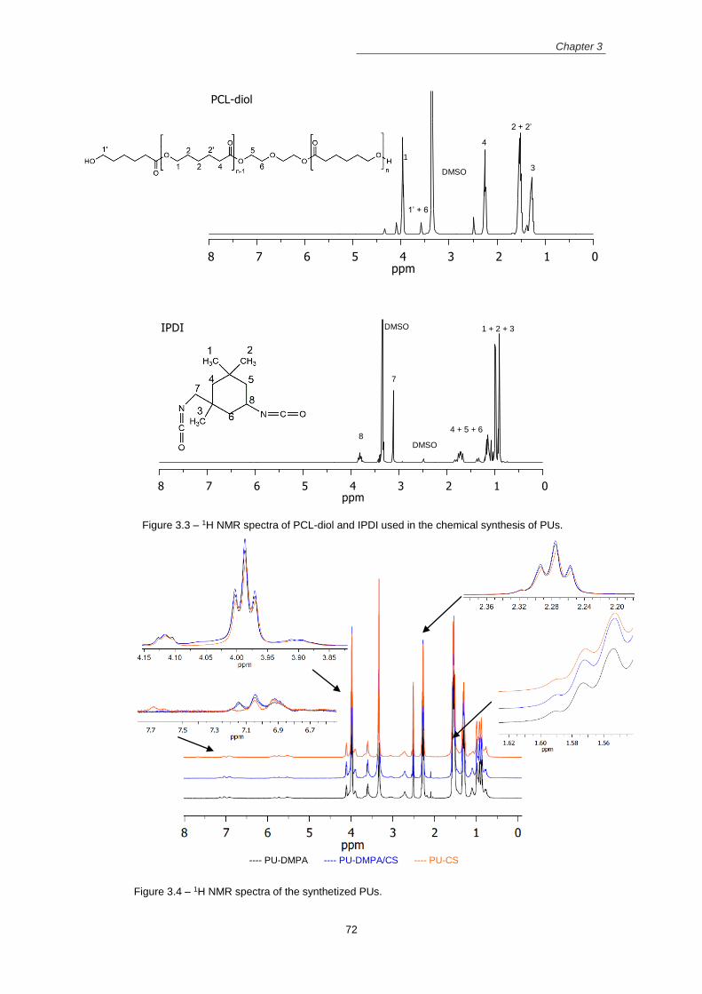
Chapter 3
72
Figure 3.3 – 1H NMR spectra of PCL-diol and IPDI used in the chemical synthesis of PUs.
Figure 3.4 – 1H NMR spectra of the synthetized PUs.
---- PU-DMPA ---- PU-DMPA/CS ---- PU-CS
1
4
2 + 2’
3
1’ + 6
DMSO
DMSO
DMSO
1 + 2 + 3
4 + 5 + 6
7
8

Chapter 3
73
PU-DMPA/CS synthesis steps were monitored using FTIR spectroscopy (Figure 3.5). In
PCL-diol IR spectrum, it is observed a peak at 1720 cm-1 corresponding to the weak C=O
stretching vibration due to the presence of –C(O)OCH2- ester bonds in the repeated units of the
PCL-diol. The wave number 3437 cm-1 is assigned to the hydroxyl band (Jeong, Kang et al. 2003),
which is absent in the PU-DMPA/CS spectrum, indicating that all hydroxyl groups reacted with
the isocyanate groups to form the PU.
The NCO groups of the IPDI are detected in the range 2270-2285 cm-1. The absence of
this band in the PU-DMPA/CS spectrum indicate the absence of –NCO free groups in the final
product. Isocyanate groups are still present on the pre-polymer spectrum, which are available to
react with the chain extenders. When the first chain extender (DMPA) is reacted with the pre-
polymer, the NCO band of the disocyanate decrease. Thus, it was formed urethane bonds
between the NCO terminal groups of the pre-polymer and the OH groups of DMPA.
The CS spectrum presents a band at 3352 cm-1, which is assigned to the N-H extension
vibration of the polysaccharide moieties (Brugnerotto, Lizardi et al. 2001). At 1657 cm-1 is
identified a peak that belongs to amide I band, resulting from the C=O stretching of N-acetyl group
of chitosan (Anitha, Divya Rani et al. 2009). At 1571 cm-1 was observed the peak corresponding
to the NH3+ deformation in the chitosan (Delair 2011).
FTIR spectra of the synthesized PUs are shown in Figure 3.6. These spectra reveal bands
that were associated with urethane and urea linkages formation (Barikani, Honarkar et al. 2009;
Barikani, Honarkar et al. 2010). The wave number range 1800 – 1600 cm-1 is assigned to the
stretching vibration of carbonyls present in ester, acetyl, urethane and urea groups. According to
the literature (Garrett, Xu et al. 2003; Yilgor, Yilgor et al. 2006; Shi, Zhan et al. 2008), free
urethane carbonyls have an absorption peak in the 1733 – 1724 cm-1 range whereas H-bonded
urethane carbonyls peak at 1715 – 1695 cm-1. The non-H bonded urea C=O are located between
1700 cm-1 and 1670 cm-1 and the urea C=O groups that form hydrogen bonds peaks in the range
1666 – 1635 cm-1. The higher intensity of the peak at 1637 cm-1 for PU-CS suggests the presence
of more H-bonded urea C=O groups due to the higher CS content.
FTIR spectra also show other characteristic absorption bands at 3365 cm -1 (N-H
stretching vibration), 2947 and 2865 cm-1 (C-H symmetric and asymmetric stretching vibrations
of CH2 groups, respectively), 1544 cm-1 (amide II, N-H bending and C-N stretching), 1460 cm-1
(CH2 bending vibration), 1360 cm-1 (C-H bending vibration), 1302 cm-1 (CH2 wagging), 1238 –
1100 cm-1 (C-O-C stretching) and 1038 cm-1 (C-O stretching).

Chapter 3
74
Figure 3.5– FTIR spectra of the precursors and the intermediate pre-polymer to reach the PU-
DMPA/CS.
Figure 3.6– FTIR spectra of the synthetized PUs.
100015002000250030003500
Tra
nsm
itta
nce (
%)
Wavenumber (cm-1
)
PU-DMPA/CS
CS
Pre-polymer + DMPA
Pre-polymer
IPDI
PCL-diol
3437 cm-1
1720 cm-1
2270 - 2285 cm-1
1640 cm-1
3352 cm-1 1657 cm
-1
1571 cm-1
80012001600200024002800320036004000
PU-DMPA
PU-DMPA/CS
PU-CS
Tra
nsm
itta
nce
Wavenumber (cm-1
)
1726 cm-1
1640 cm-1
3375 cm-1
2940 cm-1
2865 cm-1
1530 cm-1
1238 - 1038 cm-1
1360 cm-1
1458 cm-1
1302 cm-1

Chapter 3
75
Deconvolution of the C=O and NH stretching bands
The extent of microphase separation is dependent on the hydrogen bonds established
during the PU synthesis. The hydrogen bonds can be established between the hydrogen atom of
the NH in the urethane and urea linkage (donator proton) and the carbonyl urethane, carbonyl
urea and oxygen atom of ester linkage (acceptor group). Hydrogen bonds established between
the same segments conducted to superior phase segregation. FTIR is used to evaluate the extent
of hydrogen bonds and, consequently, the extent of microphase separation.
Two stretching bands are sensitive to hydrogen bonding: N-H band at 3300 – 3450 cm-1
region and C=O band at 1600 – 1800 cm-1. These bands were fitted with a sum of Gaussian
functions using the software Fityk. First, the second derivative of each region was determined to
extract the number of relative minima of the function, which corresponded to the number of
Gaussian bands used in the fitting procedure. The second derivative of the carboxylic region of
the PU-CS sample is represented in Figure 3.7, as an example.
Figure 3.7 – Carboxyl region (1600 – 1800 cm-1) of PU-CS IR spectrum: Absorbance spectrum (A);
second-derivative spectrum (B).
For the C=O stretching region, the original data, the fitting and the Gaussian curves of
PU with different CS quantities are presented in Figure 3.8. In Table 2.1 is presented the
wavenumber (cm-1) and the relative areas of the Gaussian curves, as well as the percentage of
hydrogen bonds.
Five distinct bands were identified in the carbonyl stretching band. The free C=O urethane
group was identified at 1720 – 1730 cm-1, while the hydrogen bonded urethane groups were
detected at 1710 cm-1. Bands at 1690 – 1700 cm-1, 1660 – 1680 cm-1 and 1635 - 1645 cm-1 were
ascribed to free, disordered hydrogen bonded and ordered hydrogen bonded urea carbonyl,
respectively (Queiroz, de Pinho et al. 2003; Chattopadhyay, Sreedhar et al. 2006; Yilgor, Yilgor
et al. 2006; Pereira and Oréfice 2011). As the urea carbonyl group can interact with two NH
groups, bidentate hydrogen bonds can be formed, which are stronger and induce better hard
domain cohesion than single hydrogen bonds (He, Zhang et al. 2014). Thus, it was distinguished
between order and disordered hydrogen bonded urea carbonyl.
1600 1650 1700 1750 1800
Wavenumber (cm-1
)
A
B
1729
1633
1665
1689
1710

Chapter 3
76
The percentage of free urethane carbonyl groups decrease while the hydrogen bonded
groups increase in PUs with CS (PU-DMPA/CS and PU-CS) when compared to PU-DMPA. The
increment in the CS content on the PU structure cause a decrease in ordered (12.7 to 10.3 %)
and an increase in disordered (2.48 to 16.1 %) hydrogen carbonyl urea bonds. The presence of
CS molecules with three functional groups can form a three dimensional structure, acting as a
reinforcing filler to drive microphase segregation (Ahmad, Khan et al. 2014). However, high CS
content can increase the hard segment branching, causing the disruption of the hydrogen bonds
and consequently, deteriorate the microphase separation (Sheth, Wilkes et al. 2005).
The shift of urea carbonyl band from 1641 cm-1 in PU-DMPA to 1637 cm-1 in PU-CS can
be due to the presence of soft segments dissolved in the hard segments, which prevented the
ordering of carbonyl hydrogen bonds. Consequently, the polyester oxygen compete with urea
carbonyls for the NH groups, resulting in a mixing state. Therefore, in PU-CS the CS disrupt the
hard segment order, preventing phase segregation. In PU-DMPA/CS the presence of DMPA
prevent CS branching, resulting in the organized structure that better phase segregate. However,
the phase segregation is still superior in PU-CS when compared to PU-DMPA, where urea groups
are absent and the urethane carbonyl groups are less prone to hydrogen bond.
Table 3.2 – Wavenumber (v) and relative area (A) of the 5 components of the C=O stretching band
and the percentage of carbonyl hydrogen bonded.
C=O ν
(cm-1)
A
(%)
ν
(cm-1)
A
(%)
ν
(cm-1)
A
(%)
ν
(cm-1)
A
(%)
ν
(cm-1)
A
(%)
% C=O
H-bonded
PU-DMPA 1726 52.6 1706 3.97 1689 13.4 1667 2,48 1641 12.7 33.99
PU-DMPA/CS 1729 38.5 1710 33.9 1689 8.75 1669 8.49 1639 10.3 52.71
PU-CS 1729 45.9 1711 23.7 1690 4.02 1668 16.1 1637 10.3 50.13
Figure 3.8– ATR-FTIR spectra in the carbonyl group stretching and the deconvoluted curves of (A)
PU-DMPA, (B) PU-DMPA/CS and (C) PU-CS.
In Figure 3.9 is shown the original curve, the fitting and the Gaussian curves of the N-H
stretching region of the synthetized PUs. Additional information relative to the wavenumber (cm-
1) and the areas of the Gaussian curves, as well as the percentage of N-H hydrogen bonded is
presented in Table 3.3. The N-H stretching region in 3300 – 3400 cm-1 can be resolved into four
1600 1650 1700 1750 1800
Original
Fit
1726 cm-1
1706 cm-1
1689 cm-1
1666 cm-1
1641 cm-1
Ab
so
rba
nce
Wavenumber (cm-1
)
1600 1650 1700 1750 1800
Original
Fit
1729 cm-1
1710 cm-1
1689 cm-1
1669 cm-1
1639 cm-1
Ab
so
rba
nce
Wavenumber (cm-1
)
1600 1650 1700 1750 1800
Original
Fit
1726 cm-1
1711 cm-1
1690 cm-1
1665 cm-1
1633 cm-1
Ab
so
rba
nce
Wavenumber (cm-1
)
A B C

Chapter 3
77
bands. The band at 3270 – 3280 cm-1 identify the hydrogen bonds established between the N-H
and the ester of the SS. The bands at 3309 – 3315 cm-1 and at 3368 – 3373 cm-1 are ascribed to
hydrogen bonds in the ordered and disordered state in the HS, respectively (He, Zhang et al.
2014; Shokrolahi and Yeganeh 2014) (Skarja and Woodhouse 2000). The N-H free groups are
detected at 3450 cm-1. The N-H groups can establish hydrogen bonds with either the carbonyl
group of the hard segment or the ester group of the soft segment, remaining few N-H free groups
(Park, Lim et al. 2011). A slight decrease of N-H free groups was observed in PUs with CS when
compared to the PU-DMPA, similar to what was verified in the carbonyl stretching region.
In PU-CS, the area of the band corresponding to disorder hydrogen bonds is higher and
the area of the band from ordered hydrogen bonds is smaller when compared to other PUs. In
PU-CS, the wavenumbers of both ordered and disordered hydrogen bonds bands were shifted to
lower values when compared to other PUs, indicating the superior strength of both types of
hydrogen bonds.
Table 3.3 – Wavenumber (v) and relative area (A) of the 3 components of the N-H stretching band
and the percentage of amine hydrogen bonded.
N-H v
(cm-1)
A
(%)
Ν
(cm-1)
A
(%)
ν
(cm-1)
A
(%)
ν
(cm-1)
A
(%)
% N-H
H-bonded
PU-DMPA 3276 21.9 3315 17.9 3373 56.7 3443 3.46 96.5
PU-DMPA/CS 3277 13.3 3315 19.0 3373 76.9 3458 1.56 97.8
PU-CS 3271 12.9 3309 8.71 3368 65.4 3455 2.28 98.4
Figure 3.9– ATR-FTIR spectra in the amine group stretching and the deconvoluted curves of(A)
PU-DMPA, (B) PU-DMPA/CS and (C) PU-CS.
Two forms of hydrogen bonds can be established with the N-H groups. The interaction
between the urethane/urea groups in the hard domains, which drives phase separation, and the
hydrogen bonds between the urea/urethane groups and the oxygen atoms of the esters in the
SS. The last type of hydrogen bond occurred between the SS and the HS, leading to phase mixing
between both segments. In the C=O region, a decrease in the intensity of the C=O free band
accompanied by an increase in hydrogen bonded band in PUs with CS, indicate better phase
segregation, particularly in PU-DMPA/CS. In the N-H region, the decrease of the area of the band
corresponding to the hydrogen bonds established between SS and HS (3270 cm-1) in PUs with
3150 3237 3325 3413 3500
Original
Fit
3443 cm-1
3373 cm-1
3315 cm-1
3276 cm-1
Ab
so
rba
nce
Wavenumber (cm-1
)
3150 3237 3325 3413 3500
Original
Fit
3448 cm-1
3373 cm-1
3315 cm-1
3277 cm-1
Ab
so
rba
nce
Wavenumber (cm-1
)
3150 3237 3325 3413 3500
Original
Fit
3455 cm-1
3368 cm-1
3309 cm-1
3271 cm-1
Ab
so
rba
nce
Wavenumber (cm-1
)
A B C

Chapter 3
78
CS, also confirmed a better phase segregation in these PUs. However, the disordered hydrogen
bonds in HS was superior in PUs with CS than in PU-DMPA.
Thermal analysis
TGA curves of PCL-diol, CS and synthetized PUs and their corresponding derivative plots
(DTG curves) are shown in Figure 3.10. CS shows thermal mass losses at 100 ºC due to the loss
of the entrapped water molecules and at 262 ºC due to the removal of volatile products from
thermal and oxidative decomposition (Neto, Giacometti et al. 2005). At 500 ºC, CS remains with
42.2 % of their weight.
Thermal degradation of PUs occurs between 250 and 480 ºC, al lower temperatures in
hard segments and then in soft segments (Chattopadhyay and Webster 2009), with almost no
mass remaining above 500 ºC. PCL-diol soft segments have a maximum degradation at 415 ºC
(Tsoft) in PU-DMPA and at 412 ºC in PU-DMPA/CS and PU-CS (Table 3.4). At lower temperatures,
the decomposition of urethane and urea linkages takes place, and a series of reactions may
proceed simultaneously, including the dissociation to isocyanate and alcohol, the formation of
primary amine and ofelin and the formation of secondary amine and carbon dioxide (Rueda-
Larraz, d’Arlas et al. 2009). In the last stage, hard phase degradations are observed at 258 ºC
(Thard) in PU-DMPA, at 288 ºC and 382ºC in PU-DMPA/CS and at 314 ºC in PU-CS (Table 3.4).
As the CS content in the PU backbone increases, the hard phase thermal degradation shifts to
higher temperatures.
Figure 3.10 – Mass losses (A) and the corresponding derivatives (B) vs. temperature of PCL-diol,
CS, PU-DMPA, PU-DMPA/CS and PU-CS.
The DSC curves for CS, PCL-diol and synthetized PUs are shown in Figure 3.11. The CS
present an endothermic event around 100 ºC resulting from the evaporation of water molecules
entrapped in CS. The glass transition temperature (Tg) of CS, which depends on the deacetylation
degree, molecular weight and crystallinity of CS, should appear as a small baseline step in the
DSC curve but water evaporation and degradation are likely to prevent its observation (Kittur,
Prashanth et al. 2002). No CS melting peak is observed before the onset of thermal degradation.
100 200 300 400 500
PCL-diolCSPU-DMPAPU-DMPA/CSPU-CS
Weig
ht
perc
en
t (%
)
Temperature (ºC)
100 200 300 400 500
PCL-diol
CS
PU-DMPA
PU-DMPA/CS
PU-CS
DT
G (
%/m
in)
Temperature (ºC)
A B
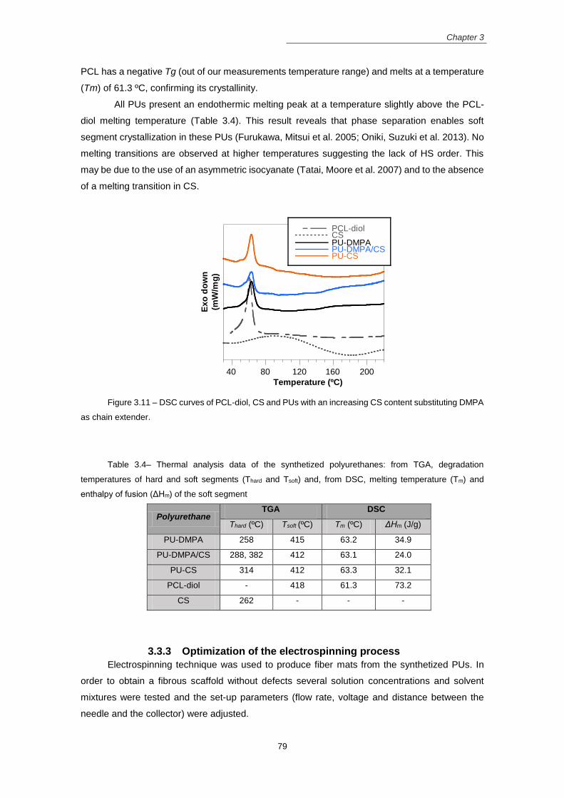
Chapter 3
79
PCL has a negative Tg (out of our measurements temperature range) and melts at a temperature
(Tm) of 61.3 ºC, confirming its crystallinity.
All PUs present an endothermic melting peak at a temperature slightly above the PCL-
diol melting temperature (Table 3.4). This result reveals that phase separation enables soft
segment crystallization in these PUs (Furukawa, Mitsui et al. 2005; Oniki, Suzuki et al. 2013). No
melting transitions are observed at higher temperatures suggesting the lack of HS order. This
may be due to the use of an asymmetric isocyanate (Tatai, Moore et al. 2007) and to the absence
of a melting transition in CS.
Figure 3.11 – DSC curves of PCL-diol, CS and PUs with an increasing CS content substituting DMPA
as chain extender.
Table 3.4– Thermal analysis data of the synthetized polyurethanes: from TGA, degradation
temperatures of hard and soft segments (Thard and Tsoft) and, from DSC, melting temperature (Tm) and
enthalpy of fusion (ΔHm) of the soft segment
Polyurethane TGA DSC
Thard (ºC) Tsoft (ºC) Tm (ºC) ΔHm (J/g)
PU-DMPA 258 415 63.2 34.9
PU-DMPA/CS 288, 382 412 63.1 24.0
PU-CS 314 412 63.3 32.1
PCL-diol - 418 61.3 73.2
CS 262 - - -
3.3.3 Optimization of the electrospinning process
Electrospinning technique was used to produce fiber mats from the synthetized PUs. In
order to obtain a fibrous scaffold without defects several solution concentrations and solvent
mixtures were tested and the set-up parameters (flow rate, voltage and distance between the
needle and the collector) were adjusted.
40 80 120 160 200
PCL-diolCSPU-DMPAPU-DMPA/CSPU-CS
Ex
o d
ow
n
(mW
/mg
)
Temperature (ºC)

Chapter 3
80
Electrospinning conditions were first optimized for the PU-DMPA/CS. Then, solutions from
PU-CS and PU-DMPA were prepared using the same solvent system, adjusting the set-up
parameters. All the scaffolds were prepared with the same solvent system for fiber characteristics
comparison, in particular the comparison of mechanical properties that are highly dependent of
the solvents used in fibers production.
The choice of the solvents used for polymer dissolution widely affect the resulting fibers.
The solvent must dissolve properly the synthetized PUs and also guarantee suitable
electrospinnability (must have appropriate boiling point, conductivity and dipole-moment). PUs
are soluble in polar solvents, the principal solvent used for PUs dissolution is the 1,1,1,3,3,3-
hexafluoro-2-propanol (HFP) (Bashur, Shaffer et al. 2009; Caracciolo, Thomas et al. 2009; Shah,
Manthe et al. 2009; Amoroso, D’Amore et al. 2011). HFP is a very aggressive and toxic solvent
that is able to break the inter-urea hydrogen bonds and to promote the appropriate dissolution of
PUs. However, other less toxic organic polar solvents were used in the dissolution of PUs to get
solutions suitable for electrospinning such as DMF (Hu, Wang et al. 2011), DMAc (Tan, Hu et al.
2015), DMSO, THF (Mondal 2014), chloroform (Riboldi, Sadr et al. 2008) and dichloromethane
(Han, Cao et al. 2011).
DMF and DMAc are dipolar aprotic solvents, which have high boiling points, dielectric
constants and dipole moments due to the presence of carbonyl groups that act as electronegative
acceptors. Solutions with these solvents have low viscosity, rendering thin and regular fibers when
electropun (Pattamaprom, Hongrojjanawiwat et al. 2006). However, the resulting fibers cannot
dry before reach the collector and fuse with each other due to the high boiling point of these
solvents (Veleirinho, Rei et al. 2008). On the other hand, solvents such as THF, chloroform and
dichloromethane have low boiling points and dielectric constants. Solutions with these solvents
have high viscosity and surface tension (Lee, Kim et al. 2002). Usually, when these solutions
were electrospun, the resulting fibers have large and irregular diameters. Due to the high viscosity
and low boiling point, the jet can dry and block the needle tip, preventing the electrospinning
process.
PUs fibers without defects are usually produced using a mixture of two solvents: one with
high boiling point and dielectric constant and other with low boiling point and dielectric constant
(Wang, Burugapalli et al. 2013; Mondal 2014; Trinca, Abraham et al. 2015). In this work, binary
mixtures of solvents such as: Chloroform:DMAc, Chloroform:DMF, THF:DMAc and THF:DMF at
50:50 proportion were used to dissolve the synthetized PUs for electrospinning. Solutions from
THF:DMF solvent mixture were the ones that when electrospun render fibrous mats without
defects and with uniform fiber diameters (Figure 3.12B). Therefore, other THF:DMF proportions
were evaluated to dissolve and electrospun PUs. PUs dissolved in 30:70 THF:DMF solvents
rendered less viscous solutions due to the high amount of DMF. Fibers produced from this
solution did not dry before reaching the collector; resulting in a bounded fiber network (Figure
3.12A). On the opposite, PUs solutions with 70:30 THF:DMF have superior viscosity and when
electrospun rendered fibrous mats with less uniform fiber diameters (Figure 3.12C) due to the fast
THF evaporation before the fibers reach the collector.

Chapter 3
81
Figure 3.12 – SEM images of the electrospun fibers produced from 20% PU-DMPA/CS solution with
THF:DMF at different ratios, using the setup parameters 16 kV, 1.0mL/h and 20cm. (A) 30:70; (B) 50:50 and
(C) 70:30. Scale bar 10 µm.
After the choice of the solvent, the concentration of the solution was optimized. It is
important to establish the critical solution concentration to produce fibrous mats without beads,
i.e., the concentration required for polymer chain entanglement (Chen, Huang et al. 2010). This
value depends on the characteristics intrinsic to the polymer, mainly the molecular weight. Higher
polymer concentrations are required for polymers with low molecular weight. Three PUs
concentrations were tested: 15, 20 and 25 wt%. Fibers with beaded morphology were observed
using the 15 wt% solution (Figure 3.13A), indicating that this concentration is not enough to
produce polymer chain entanglement. The applied electrical field and surface tension break the
polymer chains into fragments before reaching the collector. Increasing the solution concentration
to 20 wt% was enough to produce fibers with uniform diameters and without defects (Figure
3.13B). Solutions with 25 wt% concentration (Figure 3.13C) clogged at the needle tip due to their
superior viscosity, which result in irregular fibers with large diameters.
Figure 3.13– SEM images of the electrospun fibers produced from PU-DMPA/CS solution at different
concentrations with 50:50 THF:DMF solvent system, using the setup parameters16 kV, 1.0mL/h and 20cm.
(A) 15 wt%; (B) 20 wt% and (C) 25 wt%. Scale bar 10 µm.
The electrospinning set-up parameters (voltage, distance between the needle tip to the
collector and flow rate) were adjusted to get uniform fibers and a stable electrospinning process
over long periods. Small variations of the set-up parameters did not influence significantly the
fiber diameter and morphology but influence the stability of the electrospun process over time.
Therefore, in order to deposit fibers over a long period of time in order to create a matrix with
considerable thickness for further manipulation and characterization, the parameters were settled
A B C
A B C
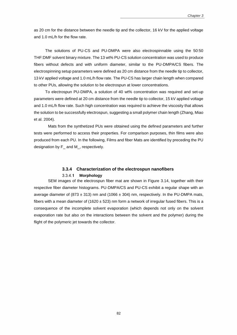
Chapter 3
82
as 20 cm for the distance between the needle tip and the collector, 16 kV for the applied voltage
and 1.0 mL/h for the flow rate.
The solutions of PU-CS and PU-DMPA were also electrospinnable using the 50:50
THF:DMF solvent binary mixture. The 13 wt% PU-CS solution concentration was used to produce
fibers without defects and with uniform diameter, similar to the PU-DMPA/CS fibers. The
electrospinning setup parameters were defined as 20 cm distance from the needle tip to collector,
13 kV applied voltage and 1.0 mL/h flow rate. The PU-CS has larger chain length when compared
to other PUs, allowing the solution to be electrospun at lower concentrations.
To electrospun PU-DMPA, a solution of 40 wt% concentration was required and set-up
parameters were defined at 20 cm distance from the needle tip to collector, 15 kV applied voltage
and 1.0 mL/h flow rate. Such high concentration was required to achieve the viscosity that allows
the solution to be successfully electrospun, suggesting a small polymer chain length (Zhang, Miao
et al. 2004).
Mats from the synthetized PUs were obtained using the defined parameters and further
tests were performed to access their properties. For comparison purposes, thin films were also
produced from each PU. In the following, Films and fiber Mats are identified by preceding the PU
designation by F_ and M_, respectively.
3.3.4 Characterization of the electrospun nanofibers
Morphology
SEM images of the electrospun fiber mat are shown in Figure 3.14, together with their
respective fiber diameter histograms. PU-DMPA/CS and PU-CS exhibit a regular shape with an
average diameter of (873 ± 313) nm and (1066 ± 304) nm, respectively. In the PU-DMPA mats,
fibers with a mean diameter of (1620 ± 523) nm form a network of irregular fused fibers. This is a
consequence of the incomplete solvent evaporation (which depends not only on the solvent
evaporation rate but also on the interactions between the solvent and the polymer) during the
flight of the polymeric jet towards the collector.

Chapter 3
83
Figure 3.14 – SEM images of electrospun fibrous matrices produced from PU-DMPA, PU-DMPA/CS
and PU-CS and their respective fiber diameter histograms. Scale bar: 10 µm.
The porosity of the fibrous mats was determined using the Archimedes method. The
porosity of the PU-DMPA, PU-DMPA/CS and PU-CS fibrous mats is 74±4, 73±4 and 46±5%,
respectively. SEM images depicted in Figure 3.14 are well correlated with the porosity values.
PU-DMPA/CS and PU-CS mats with a regular morphology have superior porosity when compared
to PU-DMPA mats. The porosity is dependent on the fiber diameter (Wang, Burugapalli et al.
2013), mats with superior fiber diameter exhibit higher pore size and pore volume. Although PU-
DMPA mats have superior fiber diameter, they were less porous than other mats due to their
fused morphology.
Mechanical properties
Typical stress-strain curves for films and mats are represented in Figure 3.15. All samples
showed high strains at break due to the soft segment.
Films exhibit stress-strain curves typical of thermoplastic elastomers, with an initial linear
region (elastic behavior extending up to about 30% strain) followed by a plastic deformation with
strain hardening at higher elongations due to strain induced crystallization of soft segments,
characteristic of a higher degree of phase separation (Ahmad, Khan et al. 2014).
The slopes of the linear regions of the films’ stress-strain curves are (2.5 ± 0.4) MPa for
PU-DMPA, (6.3 ± 0.9) MPa for PU-DMPA/CS and (6.4 ± 0.5) MPa for PU-CS (Table 3.5), showing
that the Young’s modulus is higher for films produced from PUs containing CS as chain extender.
However, the Young’s modulus does not differ between the PU-DMPA/CS film and the PU-CS
film. The increase in Young’s modulus with the presence of CS can be related to the increase in
hydrogen bonding between hard segments that, acting as physical crosslinks, results in a more
rigid structure (Delpech and Coutinho 2000; Garrett, Runt et al. 2000; Saralegi, Rueda et al. 2013)
0.0 0.5 1.0 1.5 2.0 2.5 3.0 3.5 4.0
Fre
qu
ency
Fiber Diameter / mm
0.0 0.5 1.0 1.5 2.0 2.5 3.0 3.5 4.0
Fre
qu
ency
Fiber Diameter / mm
0.0 0.5 1.0 1.5 2.0 2.5 3.0 3.5 4.0
Fre
que
ncy
Fiber Diameter / mm
PU-DMPA PU-DMPA/CS PU-CS
PU-DMPA PU-DMPA/CS PU-CS

Chapter 3
84
and to the enhancement of the hard domains cohesion due to the presence of urea bonds (absent
in PU-DMPA).
The Young’s modulus obtained for the fiber mats increases with CS content in the PU
structure: (0.82±0.04) MPa for PU-DMPA, (1.54 ± 0.30) MPa for PU-DMPA/CS and (3.25 ± 0.31)
MPa for PU-CS (Table 3.5). Comparing these results with the films’ Young’s modulus we can
conclude how processing impacts the mechanical properties – the Young’s modulus is lower for
the fiber mat’s than for the corresponding films. The mechanical properties depend on the
structure and porosity of the fibrous mats. The fibrous mats is a porous structure that possess
bonded and non-bonded structures among fibers. At low strain, the non-bonded (physically
crossed) structures are responsible for the energy dissipation due to their easily slippage, while
bonded structures resist to the applied load. At higher strains, both the breaking of the bonded
structures on the fibers and the slippage are a source of dissipation energy (Lee, Lee et al. 2005).
Figure 3.15– Tensile response curves of the electrospun nanofibrous matrices produced from PU-
DMPA, PUU-DMPA/CS and PU-CS.
The hysteresis behavior of the PUs fibrous mats were evaluated. The PUs mats were
subjected to 10 cycles of hysteresis by stretching the samples up to 80% elongation with a rate
of 80% per minute and then reversing the crosshead direction at the same rate. The hysteresis
curves are shown in Figure 3.16 as well as the hysteresis values (in %), which were obtained
from the average of at least three independent tests.
The hysteresis percentage of the first hysteresis loop is (63.0 ± 0.9) % for PU-DMPA, (77.0
± 1.3) % for PU-DMPA/CS and (53.3 ± 4.1) %.for PU-CS. PU-CS fibrous mats exhibited the lowest
percentage of hysteresis, due to their superior structural organization, higher molecular weight of
the hard segment (only CS) and also the phase segregation of hard and soft segments on this
polymer (Ertem, Yilgor et al. 2012). The first cycle has the highest hysteresis value due to superior
fibers structural disruption with strain. Then, the others cycles are smaller and turn to a constant
0
2
4
6
8
10
0 100 200 300 400 500 600 700 800
F_PU-DMPA
F_PU-DMPA/CS
F_PU-CS
M_PU-DMPA
M_PU-DMPA/CS
M_PU-CS
Str
ess
(M
Pa)
Strain (%)

Chapter 3
85
value because deformation is maintained in the same range resulting in slightly alterations in the
fibers morphology (Tang, Macosko et al. 2014). This hysteresis behavior is characteristic of
thermoplastic PUs elastomers.
Figure 3.16– Hysteresis loops after 10 cycles stretching and recovering of electrospun fibrous mats.
Crystallinity analysis
In Figure 3.17 is shown the XRD patterns for CS, PCL-diol and PU films and fibrous mats.
The fitting of the PUs diffractograms was performed by a sum of Voigt functions. As an example,
Figure 3.18 shows the fitting of the PU-DMPA/CS fibrous mats. CS exhibited two crystalline
reflections at 2θ = 10.5º and 19.7º, and a small shoulder at 21.9º. The two reflections were from
the (020) and (110) planes of chitin, respectively, which are characteristic of the semi-crystalline
structure of CS (Zhang, Xue et al. 2005). PCL-diol presented three strong reflections peaks at 2θ
= 21.4º, 22.0º and 23.7º, which corresponded to the (110), (111) and (200) planes of the crystal
structure. Other small peaks at 2θ = 15.7º and 24.5º appear due to the diffraction by the (102)
and (201) planes (Ferreira, Gomes et al. 2014).
In all difractograms were observed peaks at around 2θ = 19º, 21º and 24º are noticeable.
The broad peak at 2θ = 19º is related to the amorphous/irregular phase of PUs, resulting from the
hard segments. They interact very fast with each other due to their strong interactions, and their
disposition in the PU structure becomes amorphous without time to organize in a stable
disposition (Zia, Bhatti et al. 2009; Zhang, Jiang et al. 2011). The two sharp diffraction peaks at
21º and 24º arise from the diffraction at, respectively, (110) and (200) diffraction planes of the
PCL (Alishiri, Shojaei et al. 2014). These sharp peaks indicate the ability of soft segments to
crystallize in the PUs’ structure due to phase separation. PCL crystallized regardless of the hard
segment; therefore, the polymers phase separated at some extent.
Regarding the films, the one made of PU-DMPA/CS exhibited the highest crystalline
degree (Table 3.5). Its higher crystallinity, when compared to the PU-DMPA film, , may be related
with a higher phase segregation resulting from more and stronger hydrogen bonds due to the
presence of CS in the PU structure, including those involving the urea linkages, and, possibly,
between the ionic groups of DMPA and the CS amine group (Momtaz, Barikani et al. 2015). In
the PU-CS film, the crystalline diffraction peaks of soft segment are almost absent. CS, as the
unique chain extender, is responsible for stronger hydrogen bonding, resulting in the formation of
a rigid network that restricts the free mobility characteristic of the soft segment, decreasing the
0
0.2
0.4
0.6
0.8
1
0 20 40 60 80 100
PU-DMPA
Str
ess (
MP
a)
Strain (%)
0
0.5
1
1.5
2
0 20 40 60 80 100
PU-DMPA/CS
Str
ess (
MP
a)
Strain (%)
0
0.5
1
1.5
2
0 20 40 60 80 100
PU-CS
Str
ess (
MP
a)
Strain (%)
63.0 ± 0.9 % 77.0 ± 1.3 % 53.3 ± 4.1 %

Chapter 3
86
crystallinity of the final PU (Lin, Wei et al. 2014). For the PUs containing CS, the relative value of
the crystalline peak intensity is higher in the diffractograms of the fibrous mats than in the films.
This difference shows that the technique used to process the solutions influences the
reorganization of the PU molecules. During electrospinning, the polymeric jet is subject to strain
resulting from the repulsive electrical interactions between its charged elements. Meanwhile,
solvent evaporates from the thin polymeric jet. Due to a rapid solvent evaporation, electrospinning
may compromise the rearrangement of the semi-crystalline structure observed in a cast film
(Shah, Manthe et al. 2009; Ribeiro, Sencadas et al. 2016). However, with the appropriate solution
concentrations and applied voltages, the crystalline degree can be higher in the electrospun fibers
than in the films due to the molecular chain orientation along the fiber axis caused by the
stretching forces exerted on the polymeric solutions (Kongkhlang, Tashiro et al. 2008; Ero-
Phillips, Jenkins et al. 2012). This phenomenon seems to be dominant when electrospinning the
CS containing PUs.
For films, crystallite size, calculated from the FWHM of the (110) diffraction peak, is
approximately equal for PU-DMPA and PU-DMPA/CS, slightly higher for the latter, in line with its
higher crystalline degree. PU-CS films exhibit the smallest crystallite size, which is not surprising
given its nearly zero crystalline degree. For fibers, crystallite size is similar for all PUs, somewhat
smaller for the PU-DMPA mats that also possess the smallest crystalline degree. For PU-
DMPA/CS and PU-CS, crystallite size is nearly the same in spite of their very different crystalline
degree, suggesting that the higher crystalline degree of PU-DMPA/CS is due to a higher
abundance of crystalline regions.
Figure 3.17 – X-Ray diffractograms of PCL-diol, CS, and films and fiber mats from PU-DMPA, PU-
DMPA/CS and PU-CS.
5 10 15 20 25 30 35 40
M_PU-DMPA
M_PU-DMPA/CS
M_PU-CS
F_PU-DMPA
F_PU-DMPA/CS
F_PU-CS
PCL-diol
CS
Inte
ns
ity
2 (º)

Chapter 3
87
Figure 3.18– Fitting of the characteristic peaks of the PU-DMPA/CS fibrous mat diffractogram with
Voigt functions (red) and a cubic background (green).
Table 3.5– Results from XRD and tensile tests of films and fibrous mats. Crystalline degree, (wc,x),
full with at half maximum of the highest intensity crystalline diffraction peak, (FWHW), crystallite size, (τc),
Young’s modulus, (Y), strain at break (Ɛr), and tensile stress at 600% strain (σ600).
Films/Fibrous
Mats
XRD Mechanical tests
Crystallinity
wc,x (%)
FWHW (º) Crystallite
size τc (nm)
Young
Modulus Y
(MPa)
Elongation
at break Ɛr
(%)
Tensile
stress at
600% σ600
(MPa)
F_PU-DMPA 3.60 ± 0.17 0.379 21.1 2.5 ± 0.4 >600 1.9 ± 0.3
F_PU-DMPA/CS 11.7 ± 0.2 0.347 23.1 6.3 ± 0.9 >600 6.3 ± 0.5
F_PU-CS) 0.83 ± 0.02 0.616 13.0 6.4 ± 0.5 >600 7.6 ± 0.6
M_PU-DMPA 4.89 ± 0.03 0.432 18.5 0.82 ± 0.04 >600 1.2 ± 0.1
M_PU-DMPA/CS 31.5 ± 0.3 0.380 21.0 1.5 ± 0.3 >600 3.5 ± 0.2
M_PU-CS 7.79 ± 0.14 0.363 22.0 3.3 ± 0.3 >600 5.3 ± 0.3
XPS analysis
N, C and O atomic percentages at the PUs films’ and fiber mats’ surface were determined
by XPS. For all samples, measurements were acquired at two take-off angles – 0° and 60° – in
order to investigate the differences between the uppermost surface and the bulk in a layer ~10
Inte
nsi
ty
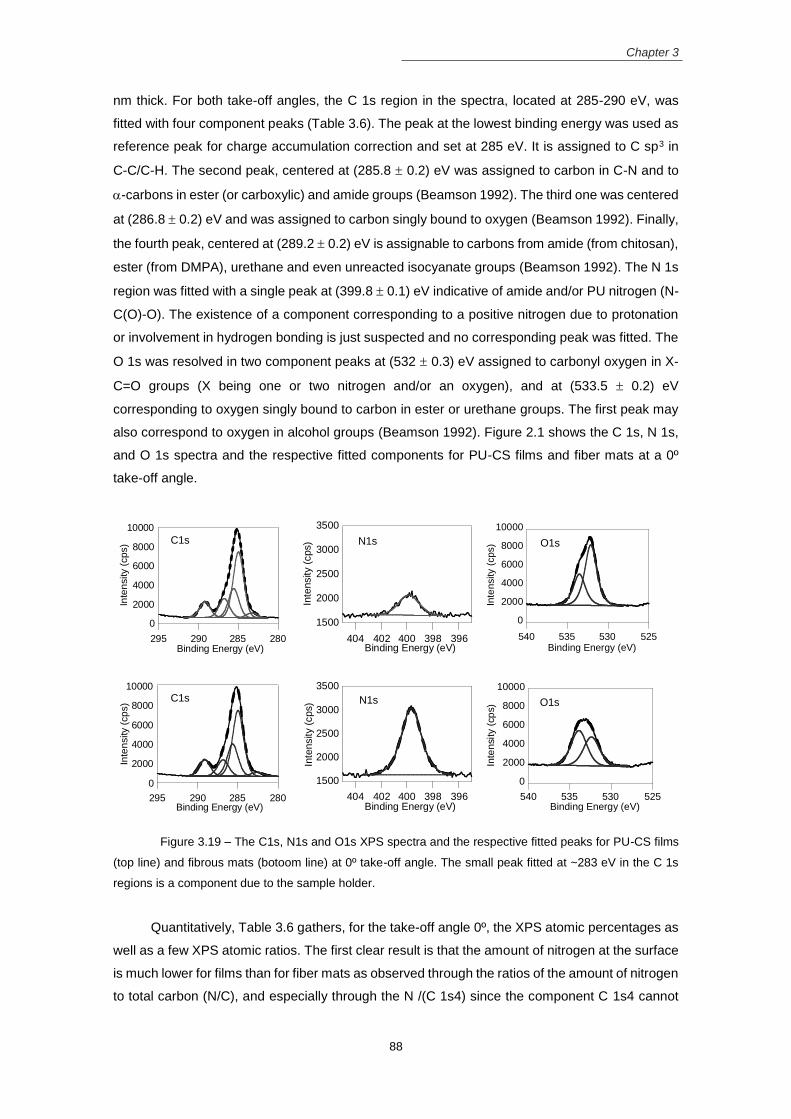
Chapter 3
88
nm thick. For both take-off angles, the C 1s region in the spectra, located at 285-290 eV, was
fitted with four component peaks (Table 3.6). The peak at the lowest binding energy was used as
reference peak for charge accumulation correction and set at 285 eV. It is assigned to C sp3 in
C-C/C-H. The second peak, centered at (285.8 0.2) eV was assigned to carbon in C-N and to
-carbons in ester (or carboxylic) and amide groups (Beamson 1992). The third one was centered
at (286.8 0.2) eV and was assigned to carbon singly bound to oxygen (Beamson 1992). Finally,
the fourth peak, centered at (289.2 0.2) eV is assignable to carbons from amide (from chitosan),
ester (from DMPA), urethane and even unreacted isocyanate groups (Beamson 1992). The N 1s
region was fitted with a single peak at (399.8 0.1) eV indicative of amide and/or PU nitrogen (N-
C(O)-O). The existence of a component corresponding to a positive nitrogen due to protonation
or involvement in hydrogen bonding is just suspected and no corresponding peak was fitted. The
O 1s was resolved in two component peaks at (532 0.3) eV assigned to carbonyl oxygen in X-
C=O groups (X being one or two nitrogen and/or an oxygen), and at (533.5 0.2) eV
corresponding to oxygen singly bound to carbon in ester or urethane groups. The first peak may
also correspond to oxygen in alcohol groups (Beamson 1992). Figure 2.1 shows the C 1s, N 1s,
and O 1s spectra and the respective fitted components for PU-CS films and fiber mats at a 0º
take-off angle.
Figure 3.19 – The C1s, N1s and O1s XPS spectra and the respective fitted peaks for PU-CS films
(top line) and fibrous mats (botoom line) at 0º take-off angle. The small peak fitted at ~283 eV in the C 1s
regions is a component due to the sample holder.
Quantitatively, Table 3.6 gathers, for the take-off angle 0º, the XPS atomic percentages as
well as a few XPS atomic ratios. The first clear result is that the amount of nitrogen at the surface
is much lower for films than for fiber mats as observed through the ratios of the amount of nitrogen
to total carbon (N/C), and especially through the N /(C 1s4) since the component C 1s4 cannot
0
2000
4000
6000
8000
10000
280285290295
Inte
nsity (
cp
s)
Binding Energy (eV)
1500
2000
2500
3000
3500
396398400402404
Inte
nsity (
cps)
Binding Energy (eV)
0
2000
4000
6000
8000
10000
525530535540
Inte
nsity (
cps)
Binding Energy (eV)
0
2000
4000
6000
8000
10000
280285290295
Inte
nsity (
cp
s)
Binding Energy (eV)
1500
2000
2500
3000
3500
396398400402404
Inte
nsity (
cps)
Binding Energy (eV)
0
2000
4000
6000
8000
10000
525530535540
Inte
nsity (
cp
s)
Binding Energy (eV)
C1s
C1s
N1s
N1s O1s
O1s

Chapter 3
89
come from any contamination. Whereas in fiber mats, that ratio is around 0.5, increasing slightly
but monotonically with the replacement of DMPA by CS, in the films, that ratio, in the absence of
CS, is 0.17 and its variation with the CS content is far from monotonic. This is indicative that some
added chitosan is present in the superficial 10 nm. But, basically, the largest contributor to the
nitrogen detected at the surface is the isocyanate.
Table 3.6 – XPS atomic percentage composition of different PU films and fibers surfaces.
Fiber mats Films
PU-DMPA PU-
DMPA/CS PU-CS PU-DMPA
PU-DMPA/CS
PU-CS
C 1s
C 1s1: C-C, C-H
35.2 41.9 36.5 45.6 47.3 36.3
C 1s2: C-N, C-H (vib)
17.9 11.6 17.8 9.0 8.4 16.0
C 1s3: C-O
9.3 8.5 9.1 8.0 8.7 10.4
C 1s4: N-C=O, O-C=O,
Urethane, -N=C=O 9.5 9.4 9.0 9.1 8.2 8.7
O 1s
O 1s1: C=O
11.6 11.5 9.9 16.5 16.2 17.7
O 1s2: C-O
11.7 12.0 12.1 10.5 8.9 9.1
N 1s amide, urethane,
cyanate 4.8 5.1 5.6 1.3 2.3 1.7
Atomic ratios
O1s1/O1s2 1.0 1.0 0.8 1.6 1.8 1.9
C 1s4/O1s1 0.8 0.8 0.9 0.6 0.5 0.5
C 1s4/O1s2 0.8 0.8 0.7 0.9 0.9 1.0
N / C 1s4 0.52 0.60 0.61 0.17 0.27 0.16
N/C 0.067 0.071 0.077 0.019 0.032 0.024
O/C 0.32 0.33 0.30 0.38 0.35 0.37
Another striking difference between mats and films, concerns the two oxygen components:
in mats they have similar areas that are similar to the one of carbon in urethane, ester, amide
groups (C 1s4 component). This is compatible with the C 1s4 being mainly composed of groups
where the number of C=O and O-C bonds are the same. This means that at the surface of the
fiber mats the segments with ester and urethane groups are dominant, the urethane being half of
the total ones at the surface (the percentage of N 1s, mainly from urethanes, is approximately
half the percentage of C 1s4). With the replacement of DMPA by CS, the slight increase of the
nitrogen amount may mean that the surface incorporates some CS. In the films, however, the O
1s lower binding energy component, is much larger than the O 1s2 component (see O 1s1 / O

Chapter 3
90
1s2 ratio in table 3), the ratio C 1s4 / O 1s2 keeping a value around 1. Moreover, in films both
components show an average increase of 0.4 eV in the position binding energy. These results
combined with the fact that the amount of nitrogen is low, are compatible with the O 1s1
component, contrarily to the mats case, not being just attributable to O=C in the groups assigned
to C 1s4 component. They should also contain C-O-C or C-OH groups where the oxygen, despite
being singly bound to carbon, may have a lower binding energy and superpose to the oxygen in
a carbonyl group.
Differences between the two take-off angles were not significant indicating that, within the
analysed depth in XPS (~10 nm), the chemical composition is homogeneous. Usually, differences
between the take-off angles are related with phase segregation behavior. However, the absence
of significant differences between the angles is not necessarily related with the absence of phase
segregation. As investigated before by Queiroz et al., the undetected differences between the
take-off angles could be explained by a segregation yielding a superficial layer thicker than the
XPS characteristic analysis depth (Queiroz, do Rego et al. 2006). Therefore, the results for phase
segregation for films are constant and extended to a layer of at least 10 nm thickness.
As mentioned above, ester groups from PCL segment are predominant at the films’ surface,
while ester and urethane are present in similar concentrations at the fiber’s surface. A possible
reason for this difference is the attraction towards the surface of groups with a higher polarity by
the surface charge carried by the polymeric jet during electrospinning.
Wettability
In Figure 3.20 is shown the results of WCA measurements performed on fiber mats and
films, as well as the representative image of the water drop on the substrates surface.
For films, the WCA was higher for PU-DMPA (103 ± 2 º) samples, indicating the
hydrophobicity of this films’ surface. This hydrophobic character is not surprising, as PCL is PUs’
main component. When DMPA is replaced by CS as chain extender, the WCA is reduced to (76
º ± 2 º) in the case of PU-DMPA/CS and to (91 º ± 5 º) in the case of PU-CS.
This shows that replacement of DMPA by CS in the PU structure reduces the film’s
hydrophobicity, which is in agreement with the XPS indication that some added chitosan is
present at the surface. Zhu et al. reported that the incorporation of macromolecules (such as CS)
in the PUs structure reduce the hydrophobicity of the final PU (Zhu, Gao et al. 2004). However,
in another study, Barikani and co-workers, who incorporated CS in the PU backbone and
produced films from aqueous PU dispersions, verified that the increment of CS on the final PU
structure increase the hydrophobicity of the film surface (Barikani, Honarkar et al. 2010), but the
values obtained are lower than ours. These diffeences may be due to differences between the
methods to produce the films.
In the fibrous mats, the WCA increases slightly with the increment of CS in the PUs
structure: (124 º ± 5 º), (139 º ± 2 º) and (153 º ± 4 º) for PU-DMPA, PU-DMPA/CS and PU-CS
mats, respectively. All the values are superior to the ones of the corresponding films. The WCA
can be influenced by the surface chemistry, roughness and fiber diameter of the fibrous mats.

Chapter 3
91
According to the surface chemistry analyzed by XPS, the fibers’ surface present urethane groups
in contrast to the films surface, which present mainly PCL. This fact alone should result in more
hydrophilic fiber mats than films, contrary to what was observed. However, the higher surface
roughness and porosity of the fibers lead to the entrapment of air bubbles at the water-material
interface, leaving less contact area for water, contributing to an increase in WCA on mats (Tijing,
Park et al. 2013). Among the mats, the higher fiber diameters contribute to inferior WCA values
(Tijing, Park et al. 2013), which can explain the lower WCA for PU-DMPA fibers that have the
larger fiber diameter.
Figure 3.20– Water contact angle values for the PUs films and mats and the respective water drop
images.
Hydrolytic and enzymatic degradation
In Figure 3.21 is shown the degradation profile of PU films and fibers immersed in both
PBS (Figure 3.21A) and lipase solution (Figure 3.21B).
In PBS, films and fibrous mats made of PU-DMPA/CS and PU-CS barely lose weight
during 60 days. Those of PU-DMPA show two distinct degradation stages: in the first month they
barely lose weight and then, a sharp weight loss is observed, a characteristic signature of bulk
erosion process.
Lipase cleave preferentially the ester bonds of the PCL soft segment in the PU structure,
resulting in α-hydroxyacids degradation products and urethane and urea fragments (Tokiwa,
Ando et al. 1990; He and Chu 2013). In comparison with PBS, the degradation of the PUs films
and mats was accelerated in lipase solution, and the mass loss profiles are typical of surface
erosion process. After 40 days, PU-CS samples exhibit the smallest weight loss.
Physico-chemical properties, such as crystallinity, hydrophilicity and water absorption are
correlated with hydrolytic degradation. Hydrophilic samples tend to have superior degradation
rates while the higher ordered structure of samples with higher crystallinity tend to slower down
the degradation process (Umare and Chandure 2008). The degradation rate of the samples
decrease with the increment of the CS content in the PU structure. A slower degradation rate is
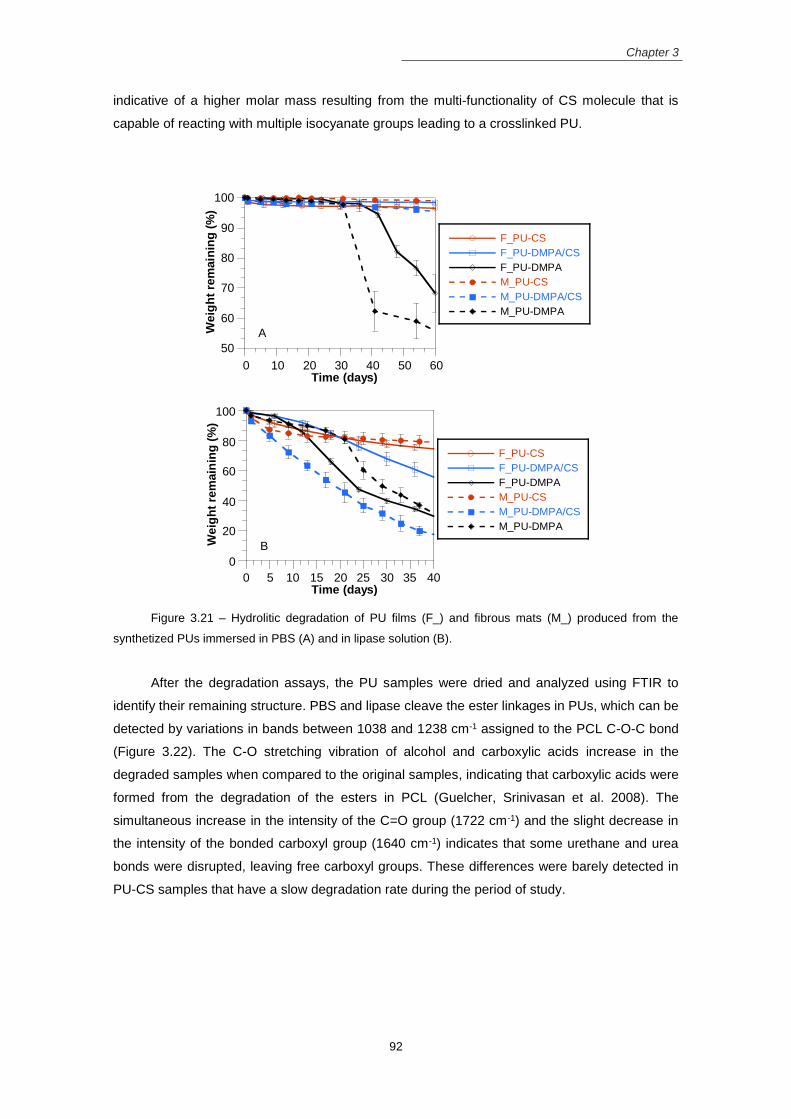
Chapter 3
92
indicative of a higher molar mass resulting from the multi-functionality of CS molecule that is
capable of reacting with multiple isocyanate groups leading to a crosslinked PU.
Figure 3.21 – Hydrolitic degradation of PU films (F_) and fibrous mats (M_) produced from the
synthetized PUs immersed in PBS (A) and in lipase solution (B).
After the degradation assays, the PU samples were dried and analyzed using FTIR to
identify their remaining structure. PBS and lipase cleave the ester linkages in PUs, which can be
detected by variations in bands between 1038 and 1238 cm-1 assigned to the PCL C-O-C bond
(Figure 3.22). The C-O stretching vibration of alcohol and carboxylic acids increase in the
degraded samples when compared to the original samples, indicating that carboxylic acids were
formed from the degradation of the esters in PCL (Guelcher, Srinivasan et al. 2008). The
simultaneous increase in the intensity of the C=O group (1722 cm-1) and the slight decrease in
the intensity of the bonded carboxyl group (1640 cm-1) indicates that some urethane and urea
bonds were disrupted, leaving free carboxyl groups. These differences were barely detected in
PU-CS samples that have a slow degradation rate during the period of study.
50
60
70
80
90
100
0 10 20 30 40 50 60
F_PU-CS
F_PU-DMPA/CS
F_PU-DMPA
M_PU-CS
M_PU-DMPA/CS
M_PU-DMPA
We
igh
t re
main
ing
(%
)
Time (days)
0
20
40
60
80
100
0 5 10 15 20 25 30 35 40
F_PU-CS
F_PU-DMPA/CS
F_PU-DMPA
M_PU-CS
M_PU-DMPA/CS
M_PU-DMPA
Weig
ht
rem
ain
ing
(%
)
Time (days)
B
A
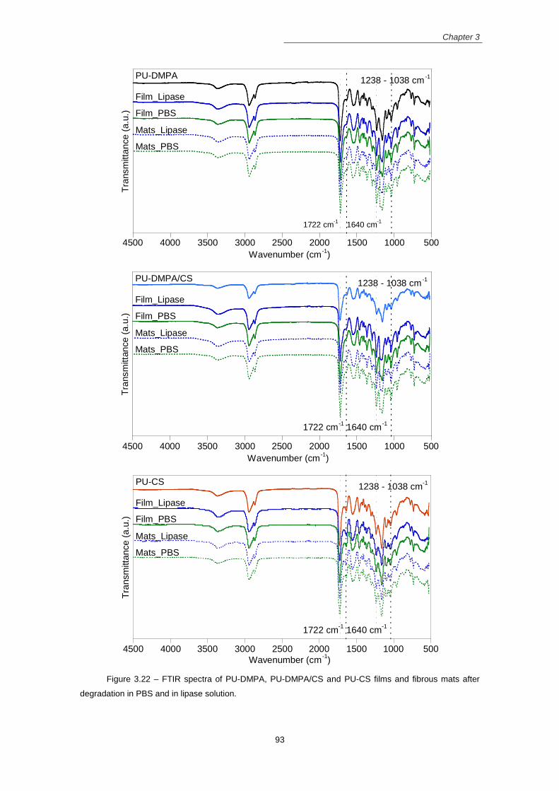
Chapter 3
93
Figure 3.22 – FTIR spectra of PU-DMPA, PU-DMPA/CS and PU-CS films and fibrous mats after
degradation in PBS and in lipase solution.
50010001500200025003000350040004500
Tra
nsm
itta
nce
(a
.u.)
Wavenumber (cm-1
)
1238 - 1038 cm-1
1640 cm-1
1722 cm-1
Mats_PBS
Mats_Lipase
Film_PBS
Film_Lipase
PU-DMPA
50010001500200025003000350040004500
Tra
nsm
itta
nce
(a
.u.)
Wavenumber (cm-1
)
PU-DMPA/CS
Film_Lipase
Film_PBS
Mats_Lipase
Mats_PBS
1238 - 1038 cm-1
1640 cm-1
1722 cm-1
50010001500200025003000350040004500
Tra
nsm
itta
nce (
a.u
.)
Wavenumber (cm-1
)
Mats_PBS
Mats_Lipase
Film_PBS
Film_Lipase
PU-CS1238 - 1038 cm
-1
1640 cm-1
1722 cm-1

Chapter 3
94
Cellular assays
Toxicity
The potential cytotoxic effects of films and electrospun mats, obtained from the synthesized
PUs, were evaluated using the extract method and a culture of HFFF2 cells. Results of the
colorimetric resazurin assay, performed with cells in contact with the extracts, are shown in Figure
3.23. Viability values are normalized to the negative control (C-, cells in complete culture medium)
and are all superior to 94%, indicating the absence of cytotoxicity. On the opposite, the positive
control (C+, cells seeded with 10% DMSO) viability is very low, which confirms the test’s sensitivity
to cell viability. Cells in contact with the pure extracts during 48h were visualized using the optical
microcospe before to perform the resazurin test (Figure 3.24). The cells cultured with PU pure
extract are stretched over all the well, established contact points with each other similar to the
cells in the C-. On the opposite, a few cells were observed in C+, confirming that most of the cells
die in the presence of DMSO.
These data indicate that neither the synthetized PUs nor their processing leads to the
leaching of soluble cytotoxic compounds from the films and fiber matrices. Therefore, they can
be considered for applications in tissue engineering.
Figure 3.23– Results of HFFF2 cells’ viability, obtained in a cytotoxicity assessment of PU-DMPA,
PU-DMPA/CS and PU-CS (A) films and (B) electrospun mats. For each material extracts were obtained by
placing a 15 mg sample in 1 mL of DMEM (15 mg/mL) and by diluting this extract by the factors 3/2 (10
mg/mL) and 3 (5 mg/mL).
Figure 3.24– Optical microscope images of the HFFF2 cells seeded in 96 well plate in contact with
pure extracts of PU- DMPA (A), PU-DMPA/CS (B) and PU-CS (C) films, negative control (live cells) (D), PU-
0
20
40
60
80
100
F_PU-DMPA F_PU-DMPA/CS F_PU-CS
15 mg/mL10 mg/mL5 mg/mLC-C+
Via
bil
ity (
%)
0
20
40
60
80
100
M_PU-DMPA M_PU-DMPA/CS M_PU-CS
Via
bil
ity (
%)
B
B
A

Chapter 3
95
DMPA (E), PU-DMPA/CS (F) and PU-CS (G) fiber mats, and positive control (dead cells) (H). Scale bar: 200
µm.
Cellular adhesion and proliferation
Viability of HFFF2 cells seeded over the surface of PU films, fibrous mats and TCP wells
(cell controls, CC) was assessed using the resazurin colorimetric assay. The test was performed
after 24 h (day 1) to evaluate the cell adhesion and the on subsequent days up to 10 days in
culture to evaluate the cell proliferation. Figure 3.25 shows the results.
The adhesion ratio, calculated as the quotient between the average for each experimental
condition and the average viability of cell controls, is reported in Table 3.7. The cell adhesion to
all mats was similar to the CC without statistically significant difference. However, cell adhesion
to all films was significantly lower (around 50%) when compared to the CC. For all PUs, the
difference between cell adhesion to films and electrospun fiber mats is also statistically significant.
Following day 1, cell population scarcely increases in films and fiber mats produced from
PU-DMPA. The incorporation of CS in the PU structure increases cell proliferation, with fibrous
mats presenting higher cellular proliferation when compared with the corresponding films.
Fibrous scaffolds produced by electrospinning are suitable substrates for cell adhesion
and proliferation due to their fibrillar structure similar to the ECM, their high surface area to volume
ratio and 3D porous architecture that allow the exchange of nutrients and toxic products conferring
the cells with an appropriate environment for their metabolism (see review: (Cui, Zhou et al.
2016)). Therefore, a better performance of the fiber mats compared to films was expected.
Other factors such as surface composition, hydrophobicity, surface roughness and
degree of microphase separation in PUs influence the cell behavior. Concerning surface
composition, fibrous mats revealed a higher content of N which increases when DMPA is replaced
by CS. The N may favor the interaction with the negatively charged cell surface membrane, which
may contribute to the observed differences between films and fiber mats cell adhesion and to the
higher proliferation ratio in samples made of PUs containing CS. Moderate hydrophilicity is
required to allow the adsorption of proteins (from culture medium and released from the cells)
retaining their native conformation (Wilson, Clegg et al. 2005). Although all PU fiber mats with CS
are hydrophobic substrates, they support the adhesion and proliferation of the fibroblasts at a
level comparable to the control. PUs containing CS, which have a higher phase segregation,
exhibit superior cell adhesion and proliferation, consistent with previous reports (Hsu, Chen et al.
2007; Dicesare, Fox et al. 2012).
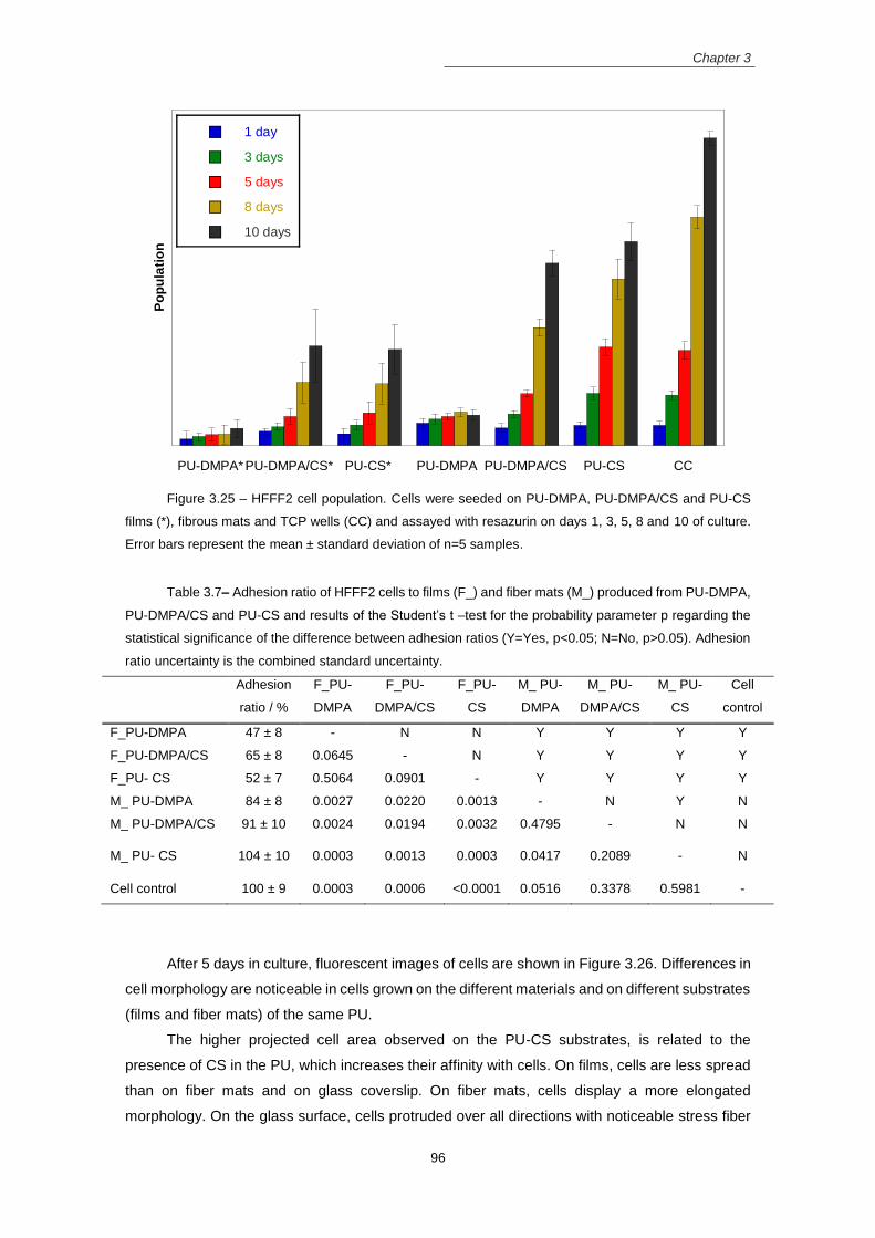
Chapter 3
96
Figure 3.25 – HFFF2 cell population. Cells were seeded on PU-DMPA, PU-DMPA/CS and PU-CS
films (*), fibrous mats and TCP wells (CC) and assayed with resazurin on days 1, 3, 5, 8 and 10 of culture.
Error bars represent the mean ± standard deviation of n=5 samples.
Table 3.7– Adhesion ratio of HFFF2 cells to films (F_) and fiber mats (M_) produced from PU-DMPA,
PU-DMPA/CS and PU-CS and results of the Student’s t –test for the probability parameter p regarding the
statistical significance of the difference between adhesion ratios (Y=Yes, p<0.05; N=No, p>0.05). Adhesion
ratio uncertainty is the combined standard uncertainty.
Adhesion
ratio / %
F_PU-
DMPA
F_PU-
DMPA/CS
F_PU-
CS
M_ PU-
DMPA
M_ PU-
DMPA/CS
M_ PU-
CS
Cell
control
F_PU-DMPA 47 ± 8 - N N Y Y Y Y
F_PU-DMPA/CS 65 ± 8 0.0645 - N Y Y Y Y
F_PU- CS 52 ± 7 0.5064 0.0901 - Y Y Y Y
M_ PU-DMPA 84 ± 8 0.0027 0.0220 0.0013 - N Y N
M_ PU-DMPA/CS 91 ± 10 0.0024 0.0194 0.0032 0.4795 - N N
M_ PU- CS 104 ± 10 0.0003 0.0013 0.0003 0.0417 0.2089 - N
Cell control 100 ± 9 0.0003 0.0006 <0.0001 0.0516 0.3378 0.5981 -
After 5 days in culture, fluorescent images of cells are shown in Figure 3.26. Differences in
cell morphology are noticeable in cells grown on the different materials and on different substrates
(films and fiber mats) of the same PU.
The higher projected cell area observed on the PU-CS substrates, is related to the
presence of CS in the PU, which increases their affinity with cells. On films, cells are less spread
than on fiber mats and on glass coverslip. On fiber mats, cells display a more elongated
morphology. On the glass surface, cells protruded over all directions with noticeable stress fiber
PU-DMPA*PU-DMPA/CS* PU-CS* PU-DMPA PU-DMPA/CS PU-CS CC
1 day
3 days
5 days
8 days
10 days
Po
pu
lati
on
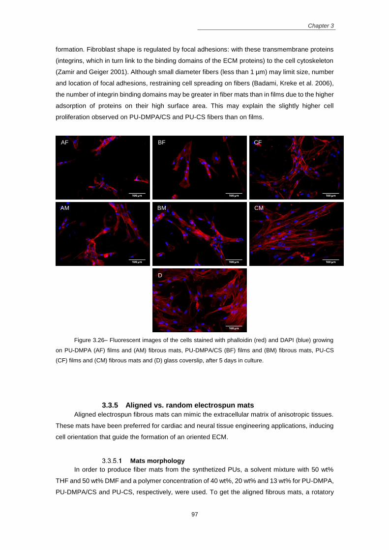
Chapter 3
97
formation. Fibroblast shape is regulated by focal adhesions: with these transmembrane proteins
(integrins, which in turn link to the binding domains of the ECM proteins) to the cell cytoskeleton
(Zamir and Geiger 2001). Although small diameter fibers (less than 1 µm) may limit size, number
and location of focal adhesions, restraining cell spreading on fibers (Badami, Kreke et al. 2006),
the number of integrin binding domains may be greater in fiber mats than in films due to the higher
adsorption of proteins on their high surface area. This may explain the slightly higher cell
proliferation observed on PU-DMPA/CS and PU-CS fibers than on films.
Figure 3.26– Fluorescent images of the cells stained with phalloidin (red) and DAPI (blue) growing
on PU-DMPA (AF) films and (AM) fibrous mats, PU-DMPA/CS (BF) films and (BM) fibrous mats, PU-CS
(CF) films and (CM) fibrous mats and (D) glass coverslip, after 5 days in culture.
3.3.5 Aligned vs. random electrospun mats
Aligned electrospun fibrous mats can mimic the extracellular matrix of anisotropic tissues.
These mats have been preferred for cardiac and neural tissue engineering applications, inducing
cell orientation that guide the formation of an oriented ECM.
Mats morphology
In order to produce fiber mats from the synthetized PUs, a solvent mixture with 50 wt%
THF and 50 wt% DMF and a polymer concentration of 40 wt%, 20 wt% and 13 wt% for PU-DMPA,
PU-DMPA/CS and PU-CS, respectively, were used. To get the aligned fibrous mats, a rotatory
AF BF CF
AM BM CM
D

Chapter 3
98
mandrel rotating at high speed was used instead of the flat collector. In the following, Random
and Aligned fibrous mats are identified by preceding the PU designation by R_ and A_,
respectively.
SEM images of the electrospun fibers with either random or aligned morphology are shown
in Figure 3.27 and Figure 3.28, respectively. The diagrams with the fiber diameter distribution are
also represented. Random and aligned PU-DMPA/CS and PU-CS fibers exhibit a regular shape
with smooth surface morphology. In random and aligned PU-DMPA mats, fibers were fused with
each other. Fibers in aligned PU-DMPA and PU-DMPA/CS mats have an average diameter of
(1121 ± 604) nm and (777 ± 294) nm, respectively, which is smaller than the diameter of random
fibers counterparts: (1620 ± 523) nm for PU-DMPA and (1066 ± 304) nm for PU-DMPA/CS. For
PU-CS mats, the fiber diameter of fibers in random mats was (873±313) nm, which is similar to
the fiber diameter of fibers in aligned mats (878 ± 352) nm. As the fibers are stretched while the
mandrel rotates at high speed, it is expected that the fibers in the aligned mats have inferior
diameter than the fibers in the random mats (Lee and Deng 2012).
The alignment degree of the fibers in the mats was studied by the analysis of the SEM
images on ImageJ software, using the preferred angle plugin with the FFT and the oval projection
method. A direct measurement of the angle of the fibers with the horizontal (0º) was taken to get
the fiber angular distribution. Both the FFT intensity graph as well as the angular distribution
histogram of the fibers in random and aligned mats are represented in Figure 3.27 and Figure
3.28, respectively. From the histogram of the angular distribution, the randomly oriented fibers
from all PUs have the fibers distributed equally in all directions while the aligned fibers have the
angular distribution centered at 90º. Aligned mats of PU-DMPA, PU-DMPA/CS and PU-CS have
88, 79, and 97% of their fibers in the 60º-120º range, respectively. The alignment degree can be
inferred from the analysis of the shape and weight of the peaks at the FFT intensity graph (Figure
3.27 and Figure 3.28, column 3). Small intense multiple peaks are indicative of fibers with less
order in the mats while fewer intense peaks are indicative of highly ordered fibers in the mats
(Ayres, Bowlin et al. 2006). Therefore, the FFT intensity graph of the fibers in the aligned mats,
which have fewer and intense peaks, corroborate the higher order of the fibers on the aligned
fibrous mats. Amongst the aligned mats, PU-CS mats exhibited superior alignment degree.

Chapter 3
99
Figure 3.27 – SEM images of randomly oriented electrospun fibrous mats (column 1) from PU-DMPA (A),
PU-DMPA/CS (B) and PU-CS (C), and the respective histograms of the fiber diameter (column 2) and the
angular distribution (column 3). Scale bar: 20 µm.
A-1
B-1
C-1
A-2 A-3
B-2 B-3
C-2 C-3
0 30 60 90 120 150 1800
10
20
30
40
50
60
Nu
mbe
r o
f fib
ers
Angle with the X-axis (º)
Inte
nsity
0 30 60 90 120 150 180
0
10
20
30
40
50
60
Nu
mbe
r o
f fib
ers
Angle with the X-axis (º)
Inte
nsity
0 30 60 90 120 150 180
0
10
20
30
40
50
60N
um
be
r o
f fib
ers
Angle with the X-axis (º)
Inte
nsity
0 0.5 1 1.5 2 2.5 3 3.5 4
Fre
qu
ency
Fiber Diameter Range (m)
0 0.5 1 1.5 2 2.5 3 3.5 4
Fre
que
ncy
Fiber Diameter Range (m)
0 0.5 1 1.5 2 2.5 3 3.5 4
Fre
qu
ency
Fiber Diameter Range (m)

Chapter 3
100
Figure 3.28– SEM images of aligned electrospun fibrous matrices (column 1) from PU-DMPA (A),
PU-DMPA/CS (B) and PU-CS (C), and the respective histograms of the diameter (column 2) and the angular
distribution (column 3). Scale bar: 20 µm.
Mechanical properties
In Figure 3.29 is presented the typical stress-strain curves of the aligned and random
fibrous mats. The Young’s modulus, obtained from the slope of the linear region of the mats’
stress-strain curves are (0.82 ± 0.04) MPa, (1.54 ± 0.30) MPa and (3.25 ± 0.31) MPa for PU-
DMPA, PU-DMPA/CS and PU-CS random mats, respectively. The Young’s modulus obtained for
aligned mats are superior to the ones obtained for random mats: (15 ± 1) MPa for PU-DMPA, (27
± 3) MPa for PU-DMPA/CS and (38 ± 2) MPa for PU-CS aligned mats. According to the elongation
at break, aligned mats exhibited smaller values than randomly mats that have elongations at
break superior to 600 %. The elongation at break of the aligned fibers are (91 ± 9) %, (116 ± 8)
% and (107 ± 9) % for PU-DMPA, PU-DMPA/CS and PU-CS, respectively.
The behavior of the electrospun mats under stress was previously described by Lee et al.
The fibers first slippage over each other and oriented on the direction of the stretching. Then, the
load is assured by the inter-fiber interactions and contact bonding points on the fibers. Finally,
A-1 A-2 A-3
B-1 B-2 B-3
C-1 C-2 C-3
0
10
20
30
40
50
60
0 30 60 90 120 150 180
Nu
mbe
r o
f fib
ers
Angle with the X-axis (º)
Inte
nsity
0 0.5 1 1.5 2 2.5 3
Fre
quency
Fiber Diameter Range (m)
0
10
20
30
40
50
60
0 30 60 90 120 150 180
Num
ber
of fibe
rs
Angle with X-axis (º)
Inte
nsity
0 0.5 1 1.5 2 2.5 3
Fre
quency
Fiber Diameter Range (m)
0 30 60 90 120 150 180
0
10
20
30
40
50
60N
um
ber
of fibe
rs
Angle with X-axis (º)
Inte
nsity
0 0.5 1 1.5 2 2.5 3
Fre
quency
Fiber Diameter Range (m)

Chapter 3
101
each individual fiber started to break until no load can be handled (Lee, Lee et al. 2005). In aligned
mats, the mechanical load was applied parallel to the fiber alignment and the fibers are stretched
in the fiber direction. Therefore, fibrous mats with aligned fibers are under stress being unable to
withstand higher deformations but handling superior loads. On the opposite, fibers in random
mats aligned first on the stress direction supporting higher elongations but with reduced loads
(Yao, Bastiaansen et al. 2014).
Snapshots were taken at the end of the mechanical tensile stress-strain test for aligned
and random mats. As an example, the snapshot of PU-CS random and aligned mats after the test
is represented in Figure 3.29. It is observed that the random mats withstand superior deformations
and the width of the sample is reduced while the mat is stretched. In the aligned mats, the fibers
start to break at early deformations.
For all mats, regardless the fiber orientation, the Young’s modulus increase with the
increment of CS content on the PU structure, which can be related to the increase in hydrogen
bonding between hard segments with the increment of CS content in PU backbone, resulting in a
more rigid structures.
Figure 3.29– Stress-strain curves of the electrospun random and aligned fibrous matrices produced
from PU-DMPA, PU-DMPA/CS and PU-CS (A). The representative snapshot of one PU-CS random (B) and
aligned (C) mat at the end of the tensile test.
Wettability
The WCA values of the random and aligned mats and the respective sessile drop image
are represented in Figure 3.30. The WCA values are (124 ± 5) º, (139 ± 2) º and (153 ± 4) º for
PU-DMPA, PU-DMPA/CS and PU-CS random mats, respectively. The WCA values of the aligned
mats are slightly inferior to the WCA of the corresponding random mats: (116 ± 2) º for PU-DMPA,
(124 ± 1) º for PU-DMPA/CS and (122 ± 2) º for PU-CS. All the fibrous mats are hydrophobic with
WCA superior to 90 º.
The morphology of the fibrous mats (alignment degree, fiber diameter and porosity) affect
the WCA (Cui, Li et al. 2008). Aligned mats have porosities and pore shapes different from the
0
2
4
6
8
10
12
0 80 160 240 320 400 480 560 640
R_PU-DMPA
R_PU-DMPA/CS
R_PU-CS
A_PU-DMPA
A_PU-DMPA/CS
A_PU-CS
Str
ess
(M
Pa)
Strain (%)
A
B
C
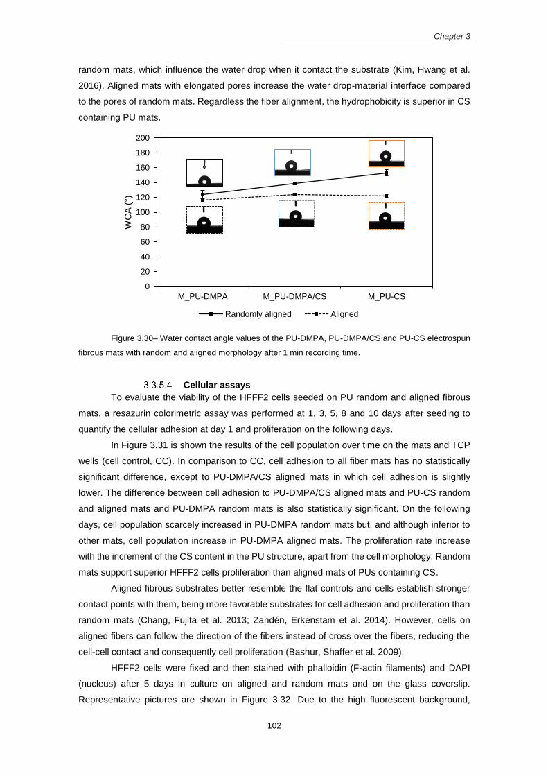
Chapter 3
102
random mats, which influence the water drop when it contact the substrate (Kim, Hwang et al.
2016). Aligned mats with elongated pores increase the water drop-material interface compared
to the pores of random mats. Regardless the fiber alignment, the hydrophobicity is superior in CS
containing PU mats.
Figure 3.30– Water contact angle values of the PU-DMPA, PU-DMPA/CS and PU-CS electrospun
fibrous mats with random and aligned morphology after 1 min recording time.
Cellular assays
To evaluate the viability of the HFFF2 cells seeded on PU random and aligned fibrous
mats, a resazurin colorimetric assay was performed at 1, 3, 5, 8 and 10 days after seeding to
quantify the cellular adhesion at day 1 and proliferation on the following days.
In Figure 3.31 is shown the results of the cell population over time on the mats and TCP
wells (cell control, CC). In comparison to CC, cell adhesion to all fiber mats has no statistically
significant difference, except to PU-DMPA/CS aligned mats in which cell adhesion is slightly
lower. The difference between cell adhesion to PU-DMPA/CS aligned mats and PU-CS random
and aligned mats and PU-DMPA random mats is also statistically significant. On the following
days, cell population scarcely increased in PU-DMPA random mats but, and although inferior to
other mats, cell population increase in PU-DMPA aligned mats. The proliferation rate increase
with the increment of the CS content in the PU structure, apart from the cell morphology. Random
mats support superior HFFF2 cells proliferation than aligned mats of PUs containing CS.
Aligned fibrous substrates better resemble the flat controls and cells establish stronger
contact points with them, being more favorable substrates for cell adhesion and proliferation than
random mats (Chang, Fujita et al. 2013; Zandén, Erkenstam et al. 2014). However, cells on
aligned fibers can follow the direction of the fibers instead of cross over the fibers, reducing the
cell-cell contact and consequently cell proliferation (Bashur, Shaffer et al. 2009).
HFFF2 cells were fixed and then stained with phalloidin (F-actin filaments) and DAPI
(nucleus) after 5 days in culture on aligned and random mats and on the glass coverslip.
Representative pictures are shown in Figure 3.32. Due to the high fluorescent background,
0
20
40
60
80
100
120
140
160
180
200
M_PU-DMPA M_PU-DMPA/CS M_PU-CS
WC
A (
°)
Randomly aligned Aligned

Chapter 3
103
images from cells on PU-DMPA/CS random mats were manipulated using the Image J software
to extract the nuclei and to remove the background. In the PU-DMPA and PU-DMPA/CS aligned
mats the nuclei were not detected even using the Image J software. The organization of the cell
cytoskeleton on the mats is different from the control. On the control, cells are well spread, while
the cells on the mats have inferior projected area. On the aligned mats, the cells elongated the
actin fibers parallel to the direction of the fiber alignment. The nuclei are also elongated on the
fiber direction. It was also clearly noticed the superior cell number and the establishment of cell-
cell contacts, forming a network structure on PU-CS random mats. These observations are in
agreement with the resazurin assay, where PU-CS random mats have a superior proliferation
rate at day 5 when compared to other mats.
Figure 3.31 – Viability assay of HFFF2 cells seeded on PU-DMPA, PU-DMPA/CS and PU-CS
random and aligned (*) mats and TCP wells (CC), after 1, 3, 5, 8 and 10 days in culture (mean ± standard
deviation, n=5). Symbols indicate statistical significance (p>0.05).
PU-DMPA PU-DMPA/CS PU-CS PU-DMPA*PU-DMPA/CS* PU-CS* CC
1 day
3 days
5 days
8 days
10 days
Po
pu
lati
on
* *
# º
º + +
#

Chapter 3
104
Figure 3.32 - Fluorescent images of phalloidin (red) and cell nuclei (DAPI, blue) stained HFFF2
cells seeded on electrospun nanofibrous mats of PU-DMPA random (AR) and aligned (AA) morphology, PU-
DMPA/CS random (BR) and aligned (BA) morphology, PU-CS random (CR) and aligned (CA) morphology
and cell control (D) at day 5 of culture.
3.4 Conclusions In this chapter, PUs extended with DMPA and/or CS were synthetized and used to
produced electrospun fiber mats and cast films.
In comparison with the corresponding films, fiber mats have more urethane and urea
groups at the surface, are more hydrophobic, have a lower Young’s modulus and a higher
crystallinity degree. Films and fibers suffered bulk erosion in PBS and surface erosion in lipase.
The fibrous structure, as well as the presence of CS, were essential to support the adhesion and
proliferation of HFFF2 cells.
In comparison to the corresponding random mats, the aligned mats have superior Young
modulus in the direction of the alignment and inferior elongation at break, are less hydrophobic
and support reduced proliferation rates of HFFF2 cells. However, the aligned mats aligned the
HFFF2 cells in the direction of the fiber alignment. In conclusion, the fiber mats obtained from
PUs extended with CS exhibited physical, chemical and biological properties suitable for soft
tissue engineering purposes.
3.5 References Ahmad, N., M. Khan, et al. (2014). "The influence of cross-linking/chain extension structures on mechanical properties of htpb-based polyurethane elastomers." Arabian Journal for Science and Engineering 39(1): 43-
51.
AR BR CR
AA BA CA
D

Chapter 3
105
Alishiri, M., A. Shojaei, et al. (2014). "Synthesis and characterization of biodegradable acrylated polyurethane based on poly (ε-caprolactone) and 1, 6-hexamethylene diisocyanate." Materials Science and Engineering: C 42: 763-773.
Amoroso, N. J., A. D’Amore, et al. (2011). "Elastomeric electrospun polyurethane scaffolds: the interrelationship between fabrication conditions, fiber topology, and mechanical properties." Advanced Materials 23(1): 106-111.
Anitha, A., V. Divya Rani, et al. (2009). "Synthesis, characterization, cytotoxicity and antibacterial studies of chitosan, O-carboxymethyl and N,O-carboxymethyl chitosan nanoparticles." Carbohydrate Polymers 78(4):
672-677. Ayres, C., G. L. Bowlin, et al. (2006). "Modulation of anisotropy in electrospun tissue-engineering scaffolds: analysis of fiber alignment by the fast Fourier transform." Biomaterials 27(32): 5524-5534.
Badami, A. S., M. R. Kreke, et al. (2006). "Effect of fiber diameter on spreading, proliferation, and differentiation of osteoblastic cells on electrospun poly (lactic acid) substrates." Biomaterials 27(4): 596-606.
Barikani, M., H. Honarkar, et al. (2009). "Synthesis and characterization of polyurethane elastomers based on chitosan and poly (ε‐caprolactone)." Journal of Applied Polymer Science 112(5): 3157-3165.
Barikani, M., H. Honarkar, et al. (2010). "Synthesis and characterization of chitosan-based polyurethane elastomer dispersions." Monatshefte für Chemie-Chemical Monthly 141(6): 653-659.
Bashur, C. A., R. D. Shaffer, et al. (2009). "Effect of fiber diameter and alignment of electrospun polyurethane meshes on mesenchymal progenitor cells." Tissue Engineering Part A 15(9): 2435-2445.
Baxter, A., M. Dillon, et al. (1992). "Improved method for ir determination of the degree of N-acetylation of chitosan." International journal of biological macromolecules 14(3): 166-169.
Beamson, G., & Briggs, D. (1992). "High Resolution XPS of Organic Polymers: The Scienta ESCA300 Database.", Chichester: John Wiley & Sons, Ltd. Bergmeister, H., N. Seyidova, et al. (2015). "Biodegradable, thermoplastic polyurethane grafts for small diameter vascular replacements." Acta biomaterialia 11: 104-113.
Brugnerotto, J., J. Lizardi, et al. (2001). "An infrared investigation in relation with chitin and chitosan characterization." Polymer 42(8): 3569-3580.
Caracciolo, P. C., V. Thomas, et al. (2009). "Electrospinning of novel biodegradable poly (ester urethane) s and poly (ester urethane urea) s for soft tissue-engineering applications." Journal of Materials Science: Materials in Medicine 20(10): 2129-2137.
Cardwell, R. D., L. A. Dahlgren, et al. (2012). "Electrospun fibre diameter, not alignment, affects mesenchymal stem cell differentiation into the tendon/ligament lineage." Journal of tissue engineering and regenerative medicine 8(12): 937–945.
Carlberg, B., M. Z. Axell, et al. (2009). "Electrospun polyurethane scaffolds for proliferation and neuronal differentiation of human embryonic stem cells." Biomedical Materials 4(4): 045004.
Chan-Chan, L., C. Tkaczyk, et al. (2013). "Characterization and biocompatibility studies of new degradable poly (urea) urethanes prepared with arginine, glycine or aspartic acid as chain extenders." Journal of Materials Science: Materials in Medicine: 1-12. Chang, J.-C., S. Fujita, et al. (2013). "Cell orientation and regulation of cell–cell communication in human mesenchymal stem cells on different patterns of electrospun fibers." Biomedical Materials 8(5): 055002.
Chattopadhyay, D., B. Sreedhar, et al. (2006). "Influence of varying hard segments on the properties of chemically crosslinked moisture‐cured polyurethane‐urea." Journal of Polymer Science Part B: Polymer Physics 44(1): 102-118.
Chattopadhyay, D. and D. C. Webster (2009). "Thermal stability and flame retardancy of polyurethanes." Progress in Polymer Science 34(10): 1068-1133.

Chapter 3
106
Chen, R., C. Huang, et al. (2010). "Preparation and characterization of coaxial electrospun thermoplastic polyurethane/collagen compound nanofibers for tissue engineering applications." Colloids and Surfaces B: Biointerfaces 79(2): 315-325.
Chen, R., L. Qiu, et al. (2009). "Electrospinning thermoplastic polyurethane-contained collagen nanofibers for tissue-engineering applications." Journal of Biomaterials Science, Polymer Edition 20(11): 1513-1536.
Cui, W., X. Li, et al. (2008). "Degradation patterns and surface wettability of electrospun fibrous mats." Polymer Degradation and Stability 93(3): 731-738.
Cui, W., Y. Zhou, et al. (2016). "Electrospun nanofibrous materials for tissue engineering and drug delivery." Science and Technology of Advanced Materials 11(1): 014108.
Daemi, H., M. Barikani, et al. (2013). "Compatible compositions based on aqueous polyurethane dispersions and sodium alginate." Carbohydrate polymers 92(1): 490-496.
Dash, M., F. Chiellini, et al. (2011). "Chitosan—A versatile semi-synthetic polymer in biomedical applications." Progress in polymer science 36(8): 981-1014.
Delair, T. (2011). "Colloidal polyelectrolyte complexes of chitosan and dextran sulfate towards versatile nanocarriers of bioactive molecules." European Journal of Pharmaceutics and Biopharmaceutics 78(1): 10-
18. Delpech, M. C. and F. M. Coutinho (2000). "Waterborne anionic polyurethanes and poly (urethane-urea) s: influence of the chain extender on mechanical and adhesive properties." Polymer testing 19(8): 939-952.
Dicesare, P., W. M. Fox, et al. (2012). "Cell–material interactions on biphasic polyurethane matrix." Journal of Biomedical Materials Research Part A 101(8): 2151-2163.
Ero-Phillips, O., M. Jenkins, et al. (2012). "Tailoring crystallinity of electrospun plla fibres by control of electrospinning parameters." Polymers 4(3): 1331-1348.
Ertem, S. P., E. Yilgor, et al. (2012). "Effect of soft segment molecular weight on tensile properties of poly (propylene oxide) based polyurethaneureas." Polymer 53(21): 4614-4622.
Ferreira, J. L., S. Gomes, et al. (2014). "Electrospinning polycaprolactone dissolved in glacial acetic acid: Fiber production, nonwoven characterization, and In Vitro evaluation." Journal of Applied Polymer Science 131(22): 41068.
Furukawa, M., Y. Mitsui, et al. (2005). "Microphase-separated structure and mechanical properties of novel polyurethane elastomers prepared with ether based diisocyanate." Polymer 46(24): 10817-10822.
Garrett, J., J. Runt, et al. (2000). "Microphase separation of segmented poly (urethane urea) block copolymers." Macromolecules 33(17): 6353-6359.
Garrett, J. T., R. Xu, et al. (2003). "Phase separation of diamine chain-extended poly (urethane) copolymers: FTIR spectroscopy and phase transitions." Polymer 44(9): 2711-2719.
Gomes, S., G. Rodrigues, et al. (2017). "Evaluation of nanofibrous scaffolds obtained from blends of chitosan, gelatin and polycaprolactone for skin tissue engineering." International Journal of Biological Macromolecules 102: 1174-1185.
Guan, J., K. L. Fujimoto, et al. (2005). "Preparation and characterization of highly porous, biodegradable polyurethane scaffolds for soft tissue applications." Biomaterials 26(18): 3961-3971.
Guan, J., F. Wang, et al. (2011). "The stimulation of the cardiac differentiation of mesenchymal stem cells in tissue constructs that mimic myocardium structure and biomechanics." Biomaterials 32(24): 5568-5580.
Guelcher, S. A. (2008). "Biodegradable polyurethanes: synthesis and applications in regenerative medicine." Tissue Engineering Part B: Reviews 14(1): 3-17.
Guelcher, S. A., A. Srinivasan, et al. (2008). "Synthesis, mechanical properties, biocompatibility, and biodegradation of polyurethane networks from lysine polyisocyanates." Biomaterials 29(12): 1762-1775.
Hafeman, A. E., K. J. Zienkiewicz, et al. (2011). "Characterization of the degradation mechanisms of lysine-derived aliphatic poly (ester urethane) scaffolds." Biomaterials 32(2): 419-429.

Chapter 3
107
Han, J., R. W. Cao, et al. (2011). "Electrospinning and biocompatibility evaluation of biodegradable polyurethanes based on L‐lysine diisocyanate and L‐lysine chain extender." Journal of Biomedical Materials Research Part A 96(4): 705-714.
He, M. and C.-C. Chu (2013). "A new family of functional biodegradable arginine-based polyester urea urethanes: Synthesis, chracterization and biodegradation." Polymer 54(16): 4112-4125.
He, Y., X. Zhang, et al. (2014). "The role of diisocyanate structure on microphase separation of solution polymerized polyureas." Polymer 55(3): 906-913.
Henriques, C., R. Vidinha, et al. (2009). "A systematic study of solution and processing parameters on nanofiber morphology using a new electrospinning apparatus." Journal of nanoscience and nanotechnology 9(6): 3535-3545.
Hsu, S., C. Chen, et al. (2007). "Cell migration on nanophase-separated poly (carbonate urethane) s." Journal of Medical and Biological Engineering 27(1): 15-21.
Hu, J., X. Wang, et al. (2011). "One‐step Electro‐spinning/netting Technique for Controllably Preparing Polyurethane Nano‐fiber/net." Macromolecular rapid communications 32(21): 1729-1734.
Huang, M., E. Khor, et al. (2004). "Uptake and cytotoxicity of chitosan molecules and nanoparticles: effects of molecular weight and degree of deacetylation." Pharmaceutical research 21(2): 344-353.
Jamadi, E. S., L. Ghasemi-Mobarakeh, et al. (2016). "Synthesis of polyester urethane urea and fabrication of elastomeric nanofibrous scaffolds for myocardial regeneration." Materials Science and Engineering: C 63:
106-116. Jeong, J. H., H. S. Kang, et al. (2003). "Polymer micelle-like aggregates of novel amphiphilic biodegradable poly (asparagine) grafted with poly (caprolactone)." Polymer 44(3): 583-591.
Jia, L., M. P. Prabhakaran, et al. (2014). "Guiding the orientation of smooth muscle cells on random and aligned polyurethane/collagen nanofibers." Journal of biomaterials applications 29(3): 364-377
Kasaai, M. R. (2007). "Calculation of Mark–Houwink–Sakurada (MHS) equation viscometric constants for chitosan in any solvent–temperature system using experimental reported viscometric constants data." Carbohydrate Polymers 68(3): 477-488.
Kim, J. I., T. I. Hwang, et al. (2016). "A Controlled Design of Aligned and Random Nanofibers for 3D Bi-functionalized Nerve Conduits Fabricated via a Novel Electrospinning Set-up." Scientific reports 6: 23761.
Kim, S. E., D. N. Heo, et al. (2009). "Electrospun gelatin/polyurethane blended nanofibers for wound healing." Biomedical Materials 4(4): 044106.
Kittur, F., K. H. Prashanth, et al. (2002). "Characterization of chitin, chitosan and their carboxymethyl derivatives by differential scanning calorimetry." Carbohydrate polymers 49(2): 185-193.
Kongkhlang, T., K. Tashiro, et al. (2008). "Electrospinning as a new technique to control the crystal morphology and molecular orientation of polyoxymethylene nanofibers." Journal of the American Chemical Society 130(46): 15460-15466.
Labow, R. S., E. Meek, et al. (1999). "The biodegradation of poly (urethane) s by the esterolytic activity of serine proteases and oxidative enzyme systems." Journal of Biomaterials Science, Polymer Edition 10(7):
699-713. Lee, J. and Y. Deng (2012). "Increased mechanical properties of aligned and isotropic electrospun PVA nanofiber webs by cellulose nanowhisker reinforcement." Macromolecular research 20(1): 76-83.
Lee, K., B. Lee, et al. (2005). "Stress-strain behavior of the electrospun thermoplastic polyurethane elastomer fiber mats." Macromolecular Research 13(5): 441-445.
Lee, K. H., H. Y. Kim, et al. (2002). "Influence of a mixing solvent with tetrahydrofuran and N, N‐dimethylformamide on electrospun poly (vinyl chloride) nonwoven mats." Journal of Polymer Science Part B: Polymer Physics 40(19): 2259-2268.
Lee, T., S. Kwon, et al. (2014). "Biodegradable sol–gel coatings of waterborne polyurethane/gelatin chemical hybrids." Progress in Organic Coatings 77(6): 1111-1116.

Chapter 3
108
Li, G., D. Li, et al. (2014). "Alternating block polyurethanes based on PCL and PEG as potential nerve regeneration materials." Journal of Biomedical Materials Research Part A 102(3): 685-697.
Lin, N., S. Wei, et al. (2014). "Green bionanocomposites from high-elasticity “soft” polyurethane and high-crystallinity “rigid” chitin nanocrystals with controlled surface acetylation." RSC Advances 4(90): 49098-
49107. Liu, C., C. Zhu, et al. (2015). "The effect of the fibre orientation of electrospun scaffolds on the matrix production of rabbit annulus fibrosus-derived stem cells." Bone research 3: 15012.
Liu, W. and Y. Cao (2007). "Application of scaffold materials in tissue reconstruction in immunocompetent mammals: our experience and future requirements." Biomaterials 28(34): 5078-5086.
Loh, J. W., J. Schneider, et al. (2010). "Spinning disc processing technology: Potential for large‐scale manufacture of chitosan nanoparticles." Journal of pharmaceutical sciences 99(10): 4326-4336.
Momtaz, M., M. Barikani, et al. (2015). "Effect of ionic group content on thermal and structural properties of polycaprolactone-based shape memory polyurethane ionomers." Iranian Polymer Journal 24(6): 505-513.
Mondal, S. (2014). "Influence of solvents properties on morphology of electrospun polyurethane nanofiber mats." Polymers for Advanced Technologies 25(2): 179-183.
Monshi, A., M. R. Foroughi, et al. (2012). "Modified Scherrer equation to estimate more accurately nano-crystallite size using XRD." World Journal of Nano Science and Engineering 2(3): 154-160.
Neto, C. d. T., J. Giacometti, et al. (2005). "Thermal analysis of chitosan based networks." Carbohydrate Polymers 62(2): 97-103.
Oniki, Y., K. Suzuki, et al. (2013). "Molecular design of environmentally benign segmented polyurethane (urea) s: effect of the hard segment component on the molecular aggregation states and biodegradation behavior." Polymer Chemistry 4(13): 3735-3743.
Oprea, S. (2010). "The effect of chain extenders structure on properties of new polyurethane elastomers." Polymer bulletin 65(8): 753-766.
Park, K., W. H. Lim, et al. (2011). "Effect of molecular shape of diisocyanate units on the microscopic/macroscopic phase separation structure of polyurethanes." Journal of Polymer Science Part B: Polymer Physics 49(12): 890-897.
Parrag, I. C., P. W. Zandstra, et al. (2012). "Fiber alignment and coculture with fibroblasts improves the differentiated phenotype of murine embryonic stem cell‐derived cardiomyocytes for cardiac tissue engineering." Biotechnology and bioengineering 109(3): 813-822.
Pattamaprom, C., W. Hongrojjanawiwat, et al. (2006). "The influence of solvent properties and functionality on the electrospinnability of polystyrene nanofibers." Macromolecular materials and engineering 291(7): 840-
847. Pereira, I. M. and R. L. Oréfice (2011). "Study of the morphology exhibited by linear segmented polyurethanes." Macromolecular Symposia, Wiley Online Library 299-300(1): 190-198.
Prabhakar, A., D. Chattopadhyay, et al. (2005). "Structural investigations of polypropylene glycol (PPG) and isophorone diisocyanate (IPDI)‐based polyurethane prepolymer by 1D and 2D NMR spectroscopy." Journal of Polymer Science Part A: Polymer Chemistry 43(6): 1196-1209.
Queiroz, D. P., M. N. de Pinho, et al. (2003). "ATR-FTIR studies of poly (propylene oxide)/polybutadiene bi-soft segment urethane/urea membranes." Macromolecules 36(11): 4195-4200.
Queiroz, D. P., A. B. do Rego, et al. (2006). "Bi-soft segment polyurethane membranes: Surface studies by X-ray photoelectron spectroscopy." Journal of membrane science 281(1): 239-244.
Ribeiro, C., V. Sencadas, et al. (2016). "Tailoring the morphology and crystallinity of poly (L-lactide acid) electrospun membranes." Science and Technology of Advanced Materials 12 (1): 015001.
Riboldi, S., N. Sadr, et al. (2008). "Skeletal myogenesis on highly orientated microfibrous polyesterurethane scaffolds." Journal of Biomedical Materials Research Part A 84(4): 1094-1101.
Chapter 3
109
Rodriguez, E. D., X. Luo, et al. (2011). "Linear/network poly (ε-caprolactone) blends exhibiting shape memory assisted self-healing (SMASH)." ACS applied materials & interfaces 3(2): 152-161.
Rueda-Larraz, L., B. F. d’Arlas, et al. (2009). "Synthesis and microstructure–mechanical property relationships of segmented polyurethanes based on a PCL–PTHF–PCL block copolymer as soft segment." European Polymer Journal 45(7): 2096-2109.
Saralegi, A., L. Rueda, et al. (2013). "Thermoplastic polyurethanes from renewable resources: effect of soft segment chemical structure and molecular weight on morphology and final properties." Polymer International 62(1): 106-115.
Schneider, C. A., W. S. Rasband, et al. (2012). "NIH Image to ImageJ: 25 years of image analysis." Nature methods 9(7): 671-675.
Shah, P. N., R. L. Manthe, et al. (2009). "Electrospinning of L-tyrosine polyurethanes for potential biomedical applications." Polymer 50(10): 2281-2289.
Sheth, J. P., G. L. Wilkes, et al. (2005). "Probing the hard segment phase connectivity and percolation in model segmented poly (urethane urea) copolymers." Macromolecules 38(13): 5681-5685.
Shi, Y., X. Zhan, et al. (2008). "Quantitative IR characterization of urea groups in waterborne polyurethanes." Journal of Polymer Science Part A: Polymer Chemistry 46(7): 2433-2444.
Shokrolahi, F. and H. Yeganeh (2014). "Soft segment composition and its influence on phase-separated morphology of PCL/PEG-based poly (urethane urea) s." Iranian Polymer Journal 23(7): 505-512.
Skarja, G. and K. Woodhouse (2000). "Structure‐property relationships of degradable polyurethane elastomers containing an amino acid‐based chain extender." Journal of Applied Polymer Science 75(12):
1522-1534. Tan, L., J. Hu, et al. (2015). "Design of bilayered nanofibrous mats for wound dressing using an electrospinning technique." Materials Letters 156: 46-49.
Tang, D., C. W. Macosko, et al. (2014). "Thermoplastic polyurethane elastomers from bio-based poly (δ-decalactone) diols." Polymer Chemistry 5(9): 3231-3237.
Tatai, L., T. G. Moore, et al. (2007). "Thermoplastic biodegradable polyurethanes: The effect of chain extender structure on properties and in-vitro degradation." Biomaterials 28(36): 5407-5417.
Tijing, L. D., C.-H. Park, et al. (2013). "Characterization and mechanical performance comparison of multiwalled carbon nanotube/polyurethane composites fabricated by electrospinning and solution casting." Composites Part B: Engineering 44(1): 613-619.
Tokiwa, Y., T. Ando, et al. (1990). "Biodegradation of synthetic polymers containing ester bonds." Polymeric Materials: Science and Engineering Division 62: 988-992.
Trinca, R. B., G. A. Abraham, et al. (2015). "Electrospun nanofibrous scaffolds of segmented polyurethanes based on PEG, PLLA and PTMC blocks: Physico-chemical properties and morphology." Materials Science and Engineering: C 56: 511-517.
Umare, S. S. and A. S. Chandure (2008). "Synthesis, characterization and biodegradation studies of poly (ester urethane) s." Chemical Engineering Journal 142(1): 65-77.
Usman, A., K. M. Zia, et al. (2016). "Chitin and chitosan based polyurethanes: A review of recent advances and prospective biomedical applications." International journal of biological macromolecules 86: 630-645.
Vatankhah, E., M. P. Prabhakaran, et al. (2014). "Phenotypic modulation of smooth muscle cells by chemical and mechanical cues of electrospun Tecophilic/gelatin nanofibers." ACS applied materials & interfaces 6(6):
4089-4101. Veleirinho, B., M. F. Rei, et al. (2008). "Solvent and concentration effects on the properties of electrospun poly (ethylene terephthalate) nanofiber mats." Journal of Polymer Science Part B: Polymer Physics 46(5):
460-471. Wang, N., K. Burugapalli, et al. (2013). "Tailored fibro-porous structure of electrospun polyurethane membranes, their size-dependent properties and trans-membrane glucose diffusion." Journal of membrane science 427: 207-217.

Chapter 3
110
Wilson, C. J., R. E. Clegg, et al. (2005). "Mediation of biomaterial-cell interactions by adsorbed proteins: a review." Tissue engineering 11(1-2): 1-18.
Wu, J., Y. Du, et al. (2012). "The engineering of organized human corneal tissue through the spatial guidance of corneal stromal stem cells." Biomaterials 33(5): 1343-1352.
Yao, J., C. W. Bastiaansen, et al. (2014). "High strength and high modulus electrospun nanofibers." Fibers 2(2): 158-186.
Yilgor, I., E. Yilgor, et al. (2006). "FTIR investigation of the influence of diisocyanate symmetry on the morphology development in model segmented polyurethanes." Polymer 47(11): 4105-4114.
Zamir, E. and B. Geiger (2001). "Molecular complexity and dynamics of cell-matrix adhesions." Journal of cell science 114(20): 3583-3590.
Zandén, C., N. H. Erkenstam, et al. (2014). "Stem cell responses to plasma surface modified electrospun polyurethane scaffolds." Nanomedicine: Nanotechnology, Biology and Medicine 10(5): 949-958.
Zdrahala, R. J. and I. J. Zdrahala (1999). "Biomedical applications of polyurethanes: a review of past promises, present realities, and a vibrant future." Journal of biomaterials applications 14(1): 67-90.
Zhang, S., L. Cheng, et al. (2003). "NMR studies of water-borne polyurethanes." Journal of applied polymer science 90(1): 257-260.
Zhang, S., J. Jiang, et al. (2011). "Facile synthesis of waterborne UV-curable polyurethane/silica nanocomposites and morphology, physical properties of its nanostructured films." Progress in Organic Coatings 70(1): 1-8.
Zhang, S., W. Miao, et al. (2004). "Reaction study of water‐borne polyurethanes based on isophorone
diisocyanate, dimethylol propionic acid, and poly (hexane neopentyl adipate glycol)." Journal of applied polymer science 92(1): 161-164.
Zhang, Y., W. He, et al. (2017). "Gemini quaternary ammonium salt waterborne biodegradable polyurethanes with antibacterial and biocompatible properties." Materials Chemistry Frontiers 1(2): 361-368.
Zhang, Y., C. Xue, et al. (2005). "Determination of the degree of deacetylation of chitin and chitosan by X-ray powder diffraction." Carbohydrate research 340(11): 1914-1917.
Zhu, Y., C. Gao, et al. (2004). "Endothelium regeneration on luminal surface of polyurethane vascular scaffold modified with diamine and covalently grafted with gelatin." Biomaterials 25(3): 423-430.
Zia, K. M., S. Anjum, et al. (2014). "Synthesis and molecular characterization of chitosan based polyurethane elastomers using aromatic diisocyanate." International journal of biological macromolecules 66: 26-32.
Zia, K. M., M. Barikani, et al. (2008). "Molecular engineering of chitin based polyurethane elastomers." Carbohydrate Polymers 74(2): 149-158.
Zia, K. M., I. A. Bhatti, et al. (2009). "XRD studies of polyurethane elastomers based on chitin/1, 4-butane diol blends." Carbohydrate Polymers 76(2): 183-187.

Chapter 4
A new biodegradable gelatin based poly(ester
urethane urea): synthesis, characterization and
electrospun scaffolds for soft tissue engineering

Chapter 4
112
4. A new biodegradable gelatin based-poly(ester urethane
urea): synthesis, characterization and electrospun scaffolds
for soft tissue engineering
4.1 Introduction
Polyurethanes (PU) have been used as biomaterials due to their adjustable physic-
chemical and biological properties. They are produced by the reaction of a polyol, a
polyisocyanate and a chain extender, to form segmented copolymers composed of soft and hard
segments that phase segregate due to the thermodynamic incompatibility between them (Oprea
2010).
To synthetize biocompatible and biodegradable PU for tissue engineering scaffolds, PU
constituents and their ratio are varied (Tatai, Moore et al. 2007; Li, Li et al. 2013). Usually,
polyesters, such as polycaprolactone, are used as soft segment since ester groups are
susceptible to hydrolysis. To avoid toxic degradation products aliphatic or lysine-derived
isocyanates are preferred (Guan, Fujimoto et al. 2005; Hafeman, Zienkiewicz et al. 2011).The
chain extender is the most variable component and can be chosen to control the degradation rate
and to introduce biological motifs for cell interaction. . Amino acids, such as aspartic acid (Chan-
Chan, Tkaczyk et al. 2013), phenylalanine (Skarja and Woodhouse 2000), arginine (He and Chu
2013), tyrosine (Sarkar, Yang et al. 2008), glutamic acid, cysteine and glycine (Perales-Alcacio,
Santa-Olalla Tapia et al. 2013), small peptide sequences, such as glycine-leucine (Parrag and
Woodhouse 2010), glycine-alanine-glycine-alanine (Liu, Xu et al. 2010), and phenylalanine-lysine
ethyl ester-phenylalanine (Wang, Zheng et al. 2014), and even natural polymers such as chitosan
(Barikani, Honarkar et al. 2009) have been used as chain extenders. Of these, PU extended with
phenylalanine (Rockwood, Woodhouse et al. 2007; Rockwood, Akins et al. 2008), tyrosine (Shah,
Manthe et al. 2009) and glycine-leucine (Parrag and Woodhouse 2010) were processed by
electrospinning (Henriques, Vidinha et al. 2009) and rendered fibrous mats with potential
applications in tissue engineering.
Gelatin is a natural polymer derived, by hydrolysis, from collagen. It has been widely used
in tissue engineering because it is biocompatible, biodegradable and have the motifs for cell
adhesion and proliferation (Kang, Tabata et al. 1999). Literature reports the fabrication of PU-
based scaffolds incorporating gelatin. There are studies that synthetized PUs modified with
gelatin. Sarkar et al (Sarkar, Chourasia et al. 2006) claimed the synthesis of a polyester urethane,
based on polyethylene lactate ester diol and gelatin. In their procedure, a prepolyurethane
solution was mixed to gelatin solution and glutaraldehyde. A gas foaming method was used to
produce sheets from the polymeric solution. In another study (Kucińska-Lipka, Gubańska et al.
2013), foams of gelatin modified polyether urethanes, synthesized using two different chain
extenders were prepared. Lee et al (Lee, Kwon et al. 2014) used a vinyl modified gelatin and a
PCL-diol based prepolymer, which was end capped to form acrylate termini, to obtain crosslinked
waterborne/gelatin films. Solutions from blends of PUs and gelatin were also used to produce

Chapter 4
113
electrospun fibrous mats for soft tissue engineering scaffolds (Kim, Heo et al. 2009; Vatankhah,
Prabhakaran et al. 2014; Jamadi, Ghasemi-Mobarakeh et al. 2016). However, the solubility of
gelatin in water requires the crosslinking of these scaffolds. Chemical crosslinkers such as
glutaraldehyde, genipin and carbodiimide are highly toxic and there are concerns about possible
cytotoxic effects of their free reactive groups (Amadori, Torricelli et al. 2015).
In this chapter, PUs based on polycaprolactone-diol (PCL-diol) and gelatin in different
Gel/PCL-diol weight proportions – 5%, 7.5% and 10% – were synthesized. These polymers will
be designed by PU-Gel-5, PU-Gel-7.5 and PU-Gel10, respectively. In the synthesis, the –NCO
terminated pre-polymer, resulting from the reaction between PCL-diol and isophorone
diisocyanate (IPDI), was reacted with gelatin without the use of any other chain extender. To the
best of our knowledge, there are no reports on the synthesis of such a polyester poly(urethane
urea) incorporating gelatin in the polymer backbone as the only chain extender The PU, obtained
as solid precipitates, were characterized chemically by proton nuclear magnetic resonance (1H
NMR) and Fourier transform infrared spectroscopy (FTIR) and thermally by thermogravimetric
analysis (TGA) and differential scanning calorimetry (DSC). Electrospun fibrous mats with random
and aligned morphology and solvent cast films, produced from a solution of PU-Gel-5 dissolved
in a mixture of N,N-dimethylformamide (DMF) and tetrahydrophuran (THF) were characterized
according to the mechanical properties, crystallinity, wettability and degradation profile. Films and
fibrous mats ability to support cell adhesion and proliferation was also tested.
4.2 Materials and methods
4.2.1 Synthesis of PU-Gel
The following materials were used in the PU-Gel synthesis: polycaprolactone-diol (PCL-
diol, Mn = 2000) and Sodium bisulfite (NaHSO3, Mw=104.06) from Acros Organics; Isophorone
diisocyanate (IPDI) from Huls, isopropanol from LabChem, dimethyl sulfoxide (DMSO, dried over
molecular sieves) from Merck and cold water fish skin gelatin (Mw= 60 kg/mol) from Sigma-Aldrich
(#G7041).
The synthesis were conducted as follows: PCL-diol (20 g) was dried under vacuum at 90
ºC during 24 h and added to a 500 cm3 four-necked reactor equipped with a mechanical stirrer, a
heating oil bath, a condenser, a dropping funnel and a nitrogen inlet and outlet. The reactor was
immersed in an oil bath whose temperature was set at 60 ºC. IPDI (8.95 g) was added dropwise
to the reactor and the temperature of the bath was raised to 90 ºC. The reaction took place during
4 h to achieve the NCO terminated pre-polymer. The temperature of the reactor was then lowered
to 50 ºC and gelatin (1.0, 1.5 or 2.0 g), previously dried at 60 ºC during 7 days and dissolved in
DMSO, was added and the reaction proceed for 1 h. To end up the reaction, NaHSO3 (2.08 g)
was added and the mixture was stirred for 30 min at high speed (800 rpm). After lowering the
temperature to 30 ºC, cold distilled water was added dropwise keeping the mixture at a reduced
stirring speed (180 rpm) to precipitate the polymer. The polymer was thoroughly washed with

Chapter 4
114
distilled water, immersed in isopropanol during 48 h and vacuum dried until constant weight. The
polymer synthesis route is outlined in Figure 4.1.
Figure 4.1– Synthesis route of polyurethane based gelatin.
4.2.2 Characterization of PU-Gel
Chemical characterization of PU-Gel was performed using Fourier Transform Infrared
Spectroscopy (FTIR) and nuclear magnetic resonance (1H NMR) analysis as described previously
(section 3.2.3). Briefly, a FT-IR Nicolet 6700 spectrometer, from Thermo Electron Corporation, in
ATR (attenuated total reflectance) mode operating with a resolution of 4 cm-1 was used to record
IR spectra. N-H and C=O IR stretching bands were fitted with Gaussian profile and constant
background using the Fityk 0.9.8 program to evaluate PU hydrogen bonds. The 1H NMR PU-Gel
spectra were recorded in DMSO-d6 (99.96% atm, Sigma-Aldrich) solution using a BrukerAvance
III 400 MHz spectrometer. Chemical shifts (δ) are registered in ppm and tetramethylsilane (TMS)
was used as the standard.
Thermogravimetric analysis (TGA) and differential scanning calorimetry (DSC) were used
to evaluate PUs thermal properties as described preciously (section 3.2.3). Briefly, data were
recorded using a TGA-DSC-STA 449F3 Jupiter equipment under nitrogen atmosphere operating
from room temperature up to 500ºC in the case of TGA and 250ºC in the case DSC at a rate of
10ºC/min. The collected data were analyzed with the control software NETZSCH Proteus.
4.2.3 Electrospinning and film casting
In order to optimize the experimental processing conditions, several solvent mixtures and
electrospinning parameters were studied. All PU-Gel were dissolved in a solvent systems
comprising 50% N,N-dimethylformamide (DMF) and 50% tetrahydrofuran (THF). The PU-Gel-10
was also dissolved in 1,1,1,3,3,3-Hexafluor-2-propanol (HFP, from Sigma-Aldrich). The PU-Gel-
CH3H3C
H3C
H2CR2 =
(CH2)5R1 =
OH R1 OH + NCO R2 NCO
O R1 O
90ºC, 4 h
CC
OO
NN
HH
R2R2 NCONCO
O R1 O
65ºC, 1 h
CC
OO
NN
HH
R2R2 NN
H
C
O
Gelatin
H
C
O
C
O
N
H
R2 NCOGelatinC
O
N
H
R2NCO
O R1 O
65ºC, 30 min
CC
OO
NN
HH
R2R2 NN
H
C
O
Gelatin
H
C
O
Gelatin C
O
N
H
R2 NC
O
N
H
R2N
Gelatin
NaHSO3
H
NaO3SC
O H
CSO3Na
O
30ºC, 1 hWater
PU-Gel
NH CH
C O
O-
C
O
NH CH
CH2
CH2
CH2
CH2
NH2
C
O
NH CH
CH3
C
O
NH C
O
N
C
O
NH CH
CH2
CH2
CH2
NH
C NH2+
NH2
C
O
NH CH2 C
O
NH CH
CH2
CH2
C O
O-
C
O
N
C
O
NH
OH
CH2 C
O
N
C
O
NH CH CH
CH3
OHCO
NH
CHOH
C
O
Gelatin =CH2
CH2
CH2
C
O
O(CH2)5 C
O
On
(CH2)2 (CH2)2O O C
O
(CH2)5O Cn
O
(CH2)5

Chapter 4
115
5 was also dissolved in other solvent systems at 50:50 proportion: DMF:Chloroform,
dimethylacetamide (DMAc):Chloroform and DMAc:THF, all solvents from Carlo Erba. Solutions
were prepared at 18 wt% and dissolved under magnetic stirring overnight.
For electrospinning, the solutions were loaded on a 5 mL syringe with a 21G stainless
steel blunt needle (internal diameter of 0.508 mm). A syringe pump (SyringePump NE-300) was
used to set the flow rate to 1.0 mL/h. A high-voltage power supply (Power Supply – iseg
T1CP300 304p) was used to apply 18 kV to the needle, while the aluminum plate, at a distance
of 20 cm from the needle tip, was kept grounded to collect the fibers. In order to facilitate the
detachment of the fiber mats to be used in physico-chemical characterization, the collector was
covered with a paper foil. Samples for cell culture were deposited on 12 mm diameter glass
coverslips, fixed to the collector. A rotatory mandrel, with 8 cm diameter, covered with paper foil
and rotating at high rotation speed (4000 rpm) was also used to collect mats with aligned
morphology.
To prepare the films, a calibrated Gardner knife from Braive Instruments was used to
spread out the solutions at a constant speed of 1.25 mm/s. After drying at ambient conditions, the
films were put under vacuum in a desiccator to complete solvent extraction.
4.2.4 Characterization of PU-Gel electrospun fibers
Scanning electron microscopy
The morphology, diameter and degree of alignment of the electrospun fibers were
determined by SEM using a Zeiss Auriga Crossbeam electron microscope. Before observation,
the samples were sputter coated with a mixture of gold/palladium (60/40). The fiber diameter was
measured by image analysis using ImageJ software (National Institutes of Health, USA) and
measurements of at least 100 fibers per sample were taken. The result is expressed as the
average ± experimental standard deviation. The alignment degree of the mats was determined
using the Fast Fourier Transform (FFT) analysis, developed by (Ayres, Bowlin et al. 2006), as
described previously (section 3.2.5).
Mechanical tests
PU-Gel films and fiber mats were subjected to uniaxial tensile tests using a tensile test
machine from Rheometric Scientific (Minimat Firmware version 3.1) with a 20 N load cell. Samples
of 10 × 10 mm2 were pulled at a rate of 2 mm/min at ambient conditions. Aligned mats were
stretched in the direction of the fiber alignment. At least 10 samples from three different
electrospun depositions or cast films were used. The Young’s modulus was determined from the
slope of the linear region of the stress-strain curve and expressed as the average ± experimental
standard deviation.
Hysteresis tests were also performed: 10 cycle hysteresis behavior was evaluated by
stretching the samples to 80% elongation with a crosshead speed of 10 mm/min and afterwards,

Chapter 4
116
immediately retract them at the same crosshead speed. The tests were conducted at room
temperature and at least three samples from each mat were tested.
X-ray diffraction analysis
The crystalline structure of PU-Gel films and fibrous mats was analyzed by XRD with a
PANalytical X’Pert PRO X-ray diffractometer, using CuKα radiation (λ = 1.54060 Å) in the range
5°<2θ<40° with a 0.1º step. The diffractograms were fitted with a sum of pseudo-Voigt functions,
assuming a background fitted to a second degree polynomial. The crystalline degree, 𝑤𝑐,𝑥, and
crystallite size, 𝜏, were calculated using the equations described in section 3.2.5.4.
Water contact angle
The wettability of PU-Gel films and fibrous mats was assessed by static WCA
measurements at room temperature and 98% humidity, using a contact angle goniometer
(OCA15, DataPhysics Instruments GmbH, Filderstadt, Germany). Water drops with 5 µL were
generated with an electronic micrometric syringe and carefully deposited on the samples surface
and contact angle value was acquired within the following 5 min (the shape of the drops was
stable in that period). The collected information was analyzed using the SCA v.4.3.12 and v.4.3.16
software. The results are expressed as the average ± standard deviation of at least five
measurements recorded in different regions of the sample.
Degradation assays
Hydrolytic and enzymatic degradation of PU-Gel films and fiber mats were evaluated,
over a period of 37 days, from mass loss measurements as described in section 3.2.5.7 using
different degradation media. For the hydrolytic degradation studies, the degradation medium was
a phosphate buffer saline (PBS, pH 7.4 ± 0.2). Enzymatic degradation studies were performed
using lipase (activity: 27 U/mg from Amano Enzyme Inc.) prepared at a concentration of 10 U/mL,
in accordance with (Labow, Meek et al. 1999) and trypsin (activity: 256 U/mg from Amresco)
prepared at a concentration of 104 U/mL, as reported by (Mandalari, Faulks et al. 2008). All
solutions were supplemented with 0.04 % w/v sodium azide (Merck, to prevent contamination by
gram-negative bacteria). Enzymatic solutions were replaced every other day to maintain a
constant enzymatic activities.
Cell culture experiments
In vitro studies were performed using human fetal foreskin fibroblasts (HFFF2 cell line,
obtained from ECACC, UK) cultured in Dulbecco’s modified Eagle’s medium (DMEM, catalog
#D5030, Sigma-Aldrich), supplemented with GlutaMAX (#35050-038), 10% v/v fetal bovine serum
(FBS, #10270106), 100 units/mL of penicillin, 100 μg/mL streptomycin (#15140122) and 2.50
μg/mL amphotericin B (#15290018) all from Life Technologies. Cells were incubated at 37 ºC in
a 5% CO2 humidified atmosphere incubator (Sanyo MCO-19AIC(UV)).
Cell viability was assayed using the colorimetric resazurin assay described in detail in
section 3.2.5.8.

Chapter 4
117
Indirect cytotoxicity test
PU-Gel films and fibrous mats were checked for cytotoxicity using the extract method in
accordance with the International Standard ISO 10993-5. To get the extracts, samples were cut,
weighted, sterilized under 254 nm UV light during 30 min on each side, immersed in culture
medium without FBS (1 mL of medium per 15 mg of sample) and incubated at 37 ºC in orbital
agitation during 48 h. HFFF2 cells were seeded at a density of 20×103 cells/cm2 and incubated at
37 ºC in a 5% CO2 humidified atmosphere during 24 h. After this period, the medium was replaced
with the pure extracts and their dilutions (dilution factors 3/2 and 3) supplemented with 10% FBS.
Negative (viable cells) and positive (cells in a cytotoxic environment) controls were established
by culturing cells with complete medium and complete medium with 10% DMSO, respectively.
After 48 h in contact with the extracts, the resazurin viability assay was performed.
Cell adhesion and proliferation
Electrospun fibers deposited on coverslips were sterilized (as previously describes),
washed three times with PBS and soaked in complete culture medium. HFFF2 cells were seeded
at a density of 10×103 cells/cm2, over a 0.5 cm2 area on each sample held by home-made Teflon
inserts, which were placed in a 24-well tissue culture plate (Sarstedt, Germany). Cell controls
were set by seeding cells at the same density over the surface of the tissue culture plate (TCP)
wells for viability assays, and on glass coverslips for fluorescence imaging. Cells were incubated
at 37 ºC in a 5% CO2 humidified atmosphere. The viability was accessed after 1, 3, 5, 7, 9, and
11 days using the resazurin assay to access cell adhesion and proliferation. After 5 days of
culture, the cytoskeleton and nucleus of cells growing in fibrous mats and coverslips were stained
with Acti-stainTM 555 Fluorescent Phalloidin (from Cytoskeleton, Inc.) and 4’,6-Diamidino-2-
Phenylindole, Dilactate – DAPI (from Molecular ProbesTM, ThermoFisher Scientific, Inc.), as
described in section 3.2.5.8.
4.3 Results and discussion
4.3.1 PU-Gel Characterization
PU-Gel was synthetized using a two steps procedure. In the first step pre-polymer is
formed by reacting hydroxyl (-OH) groups of PCL-diol with -NCO groups of IPDI, establishing
urethane bonds. In the second step, -OH and amine (-NH2) groups of gelatin react with the pre-
polymer –NCO, resulting in the formation of new urethane and urea bonds, respectively.
Chemical characterization
The 1H NMR spectra of PCL, IPDI, gelatin and PU-Gel 1.0 g are represented in Figure
4.2. In the PU-Gel-5 spectrum, the peaks between 0.75 and 1.20 ppm are due to methyl groups
of IPDI (Zhang, Cheng et al. 2003) and of gelatin aminoacids (Hu, Li et al. 2011); the peak with
the smallest chemical shift derives from amino acids with side chains with terminal methyl groups

Chapter 4
118
(alanine, valine, leucine and isoleucine). Methylene groups of PCL (–OCH2CH2CH2CH2CH2COO–
) are observed at 3.95-3.98, 1.47-1.57, 1.24-1.32 and 2.24-2.27 ppm, respectively (Zia, Barikani
et al. 2008). Resonances from methylene linked to urea N (NHCONH–CH2) are present at 2.73
ppm (Li, Kong et al. 2015). The peak at 3.12 ppm in IPDI spectrum, assigned to the methylene
protons next to –NCO (Zhang, Cheng et al. 2003), does not appear in PU-Gel-5, indicating that
urethane/urea bonds were formed. CH2 groups attached to the urethane oxygen atom (–
CH2OCONH) are detected at 3.89 – 3.91 ppm (Zhang, He et al. 2017). Peaks in the region 5.68-
5.86 ppm are assigned to the urea NH (–NHCONH–) (Zhang, Cheng et al. 2003; Li, Zhao et al.
2014; Li, Kong et al. 2015). These peaks are observed in the PU-Gel-5 spectrum, confirming the
presence of the urea group and demonstrating that gelatin bonds to the pre-polymer,
incorporating the polymer structure. Weak peaks at 6.82–7.24 ppm position are ascribed to
urethane NH (–NHCOO–) (Zhang, Cheng et al. 2003).
Figure 4.2– 1H NMR spectra of PU-Gel 1.0 g and its precursors in the range between 0.5 ppm to
5.0 ppm. For chemical shifts higher than 5.0 ppm, PCL and IPDI spectra didn´t reveal any peak. Spectra of
fish gelatin and PU-Gel 1.0g between 5.0 ppm and 8.0 ppm (A). Spectra of PU-Gel 1.0g in the range 3.65 –
4.20 ppm (B).

Chapter 4
119
Figure 4.3 presents the FTIR spectra of PU-Gel 1.0g, PU-Gel 1.5g and PU-Gel 2.0g, as
well as the spectra of their precursors: PCL, IPDI and fish gelatin, and the intermediate pre-
polymer.
In comparison with the pre polymer, the spectra of all PU-Gel reveal the increase in the
intensity of the band at 3360 cm-1 (N-H stretching), the extinction of the IPDI peak at 2260 cm-1
(out of phase -N=C=O stretch) and the appearance of a new peak at 1640 cm-1 (C=O stretching),
which increases with the amount of gelatin added to the pre-polymer. The peak at 1640 cm-1 is
characteristic of the gelatin amide I band but it may also be due to H-bonded urea C=O groups
(Garrett, Xu et al. 2003; Yilgor, Yilgor et al. 2006; Shi, Zhan et al. 2008). At around 1540 cm-1 and
1236 cm-1 are the bands due to the urea N-H deformation and C-N stretching, respectively, which
overlap with the amide II and amide III bands of gelatin. All these changes can be related to the
formation of new urea/urethane bonds (Li, Kong et al. 2015) due to incorporation of gelatin in the
PU-Gel structure.
The C-H symmetric and asymmetric vibrations from CH2 groups are identified at 2940
and 2865 cm-1, respectively. The carbonyl stretching vibration of PCL-diol and urethane bonds
are detected around 1725 cm-1.
Figure 4.3– FTIR spectra of PUs synthetized with different amounts of gelatin and their constituents.
80012001600200024002800320036004000
Tra
nsm
itta
nce (
%)
Wavenumber (cm-1
)
3365 cm-1
2260 cm-1
1725 cm-1
1640 cm-1
1530 cm-1
1236 cm-1
PCL
IPDI
Pre-polymer
Fish gelatin
PU-Gel-5
PU-Gel-7.5
PU-Gel-10

Chapter 4
120
Deconvolution of N-H and C=O bands
The extent of microphase separation depends on the hydrogen bonding established in
PUs, which can be studied by the analysis of the amine (3300 – 3450 cm-1) and carboxyl (1600 –
1800 cm-1) stretching regions of the PUs FTIR spectra. These regions were fitted with a sum of
Gaussian functions using the software Fityk.
The original data, the fitting and the Gaussian curves for each PU-Gel carboxylic region
are presented in Figure 4.4. In Table 4.1 is presented the wavenumber (cm-1), the relative areas
of Gaussian curves and the percentage of hydrogen bonds. Five Gaussian curves fit the carboxyl
region of PUs. At 1720 – 1730 cm-1 is detected the free C=O urethane groups and at 1705 – 1710
cm-1 is observed the hydrogen bonded C=O urethane groups. The free, disordered and ordered
hydrogen bonded C=O urea groups were observed at 1690 – 1700 cm-1, 1660 – 1680 cm-1 and
1635 - 1645 cm-1, respectively.
Regarding this band, the free C=O urethane groups increase while the hydrogen bond
C=O urethane groups decrease with the increment of gelatin in the PU backbone. The PU-Gel-5
has higher percentage of hydrogen bonds, with a superior degree of microphase segregation.
The microphase separation is prevented in PU-Gel-7.5 and PU-Gel10. Increasing the gelatin
content in PU backbone, destroy the formed hydrogen bonds and destabilize the phase
segregation. This behavior was observed when chain extenders with more than two functional
groups were used in the PU synthesis (Sheth, Wilkes et al. 2005; Ahmad, Khan et al. 2014).
Figure 4.4– C=O stretching band analysis for PU-Gel with different gelatin contents: (A) 5%; (B)
7.5%; (C) 10%.
Table 4.1– Wavenumber (v) and relative area (A) of the 5 components of the C=O stretching band
and the percentage of carbonyl hydrogen bonded.
C=O ν
(cm-1)
A
(%)
ν
(cm-1)
A
(%)
ν
(cm-1)
A
(%)
ν
(cm-1)
A
(%)
ν
(cm-1)
A
(%)
% of C=O
H-bonded
5% 1729 38.0 1709 32.9 1689 6.10 1673 10.3 1641 12.7 55.9
7.5% 1728 42.5 1709 26.4 1686 4.74 1666 11.3 1636 15.1 52.8
10% 1729 42.1 1710 22.3 1687 7.88 1664 11.8 1635 15.9 50.0
1600 1640 1680 1720 1760
Original
Fit
1729 cm-1
1709 cm-1
1689 cm-1
1673 cm-1
1642 cm-1
Abso
rban
ce
Wavenumber (cm-1
)
1600 1640 1680 1720 1760
Original
Fit
1728 cm-1
1709 cm-1
1687 cm-1
1666 cm-1
1636 cm-1
Abso
rban
ce
Wavenumber (cm-1
)
1600 1640 1680 1720 1760
Original
Fit
1729 cm-1
1710 cm-1
1687 cm-1
1664 cm-1
1635 cm-1
Abso
rban
ce
Wavenumber (cm-1
)
A B C

Chapter 4
121
For the amine region, the original data, the fitting and the Gaussian curves for PU-Gel are
represented in Figure 4.5. The wavenumber (cm-1), the relative Gaussian areas and the
percentage of hydrogen bonds in the amine region are detailed in Table 2.1. The amine region is
fitted with four distinct bands, which are from: the amine hydrogen bonded to oxygen polyester
SS at 3270 – 3280 cm-1, the order hydrogen bonds in HS at 3309 – 3315 cm-1, the disorder
hydrogen bond in HS at 3368 – 3373 cm-1 and the free amines at 3450 cm-1.
From the analysis of the amine stretching region, it was observed that PU-Gel-5 has lower
free amine groups and superior hydrogen bonded amine groups. For all PUs, the hydrogen bonds
in the hard segment are mostly disordered due to the higher functionality of gelatin that prevent
the HS to pack efficiently. PU-Gel-5 has the lowest percentage of hydrogen bonds established
between the HS and the SS (24.0 %), indicating that the remaining hydrogen bonds are mainly
established between HS, which contribute to superior phase segregation.
Figure 4.5 – N-H stretching band analysis for PU-Gel with different gelatin contents: (A) 5%; (B)
7.5%; (C) 10%.
Table 4.2– Frequency (v) and relative area (A) of the 4 components of the N-H stretching band and
the percentage of amine hydrogen bonded.
N-H v
(cm-1)
A
(%)
ν
(cm-1)
A
(%)
ν
(cm-1)
A
(%)
ν
(cm-1)
A
(%)
% of N-H
h-bonded
5% 3279 24.0 3326 30.3 3379 45.7 3445 2.57 98.4
7.5% 3283 25.2 3323 19.0 3376 55.9 3453 2.14 97.9
10% 3281 27.4 3327 26.4 3379 46.3 3452 2.32 97.7
Thermal characterization
In Figure 4.6 is shown the DSC thermograms of PU extended with different amounts of
gelatin, as well as those of PCL and fish gelatin.
PCL displays a melting peak at a temperature (Tm) of 61.3 ºC, confirming its crystallinity,
while in fish gelatin a broad endothermic peak around 100 ºC is mainly related with water
evaporation. The absence of a melting transition peak in fish gelatin is due to its essentially
denatured amorphous structure (absence of helix-coil transitions) (Chuaynukul, Prodpran et al.
2014).
3150 3220 3290 3360 3430 3500
Original
Fit
3445 cm-1
3379 cm-1
3326 cm-1
3279 cm-1
Abso
rban
ce
Wavenumber (cm-1
)
3150 3220 3290 3360 3430 3500
Original
Fit
3453 cm-1
3376 cm-1
3323 cm-1
3283 cm-1
Abso
rban
ce
Wavenumber (cm-1
)
3150 3220 3290 3360 3430 3500
Original
Fit
3452 cm-1
3379 cm-1
3327 cm-1
3281 cm-1
Abso
rban
ce
Wavenumber (cm-1
)
A B C

Chapter 4
122
In all PU-Gel thermograms, an endothermic melting peak appears around 50 ºC – 60ºC
due to the melting of the soft segment phase (PCL). As can be seen in Table 4.3, in the case of
PU-Gel-5, this peak occurs at about the PCL melting temperature but, as the gelatin content in
the PU backbone increases, it shifts to lower temperatures (51.3 ºC for PU-Gel7.5 and 51.8 ºC
for PU-Gel-10). Values of the melting enthalpy (ΔHm) and degree of crystallinity (Xc) of the soft
segment were calculated and are also presented in Table 4.3. A decrease of the melting enthalpy
with the increase of gelatin content is also observed. This denotes a decrease of the soft segment
crystallinity degree. The reduction can be explained by the extent of crosslinking between gelatin
and the pre-polymer, which gives rise to a rigid 3D structure preventing microphase separation
(Zou, Chen et al. 2015). Thus, the increment of gelatin in the PU backbone results in a phase
mixed structure. No melting transitions are observed at higher temperatures, indicating the lack
of hard segment order (Tatai, Moore et al. 2007).
Figure 4.6– DSC thermograms of PUs synthesized with different amounts of gelatin.
Table 4.3– Thermal analysis data of PU-Gel. From DSC: Melting temperature (Tm), melting enthalpy
(ΔHm) and crystallinity (Xc) of the soft segment. From TGA: degradation temperatures of the two observed
stages (T1 and T2) and corresponding weight losses (Δw1 and Δw2).
Polyurethanes
DSC TGA
Tm (ºC) ΔHf (J/g) Xc (%) Thard
(ºC)* Δw1 (wt%) Tsoft (ºC)* Δw2 (wt%)
PU-Gel-10 51.8 2.54 1.86 342 13.5 415 62.0
PU-Gel-7.5 51.3 7.85 5.77 338 13.8 413 63.0
PU-Gel-5 60.9 11.7 8.57 334 13.9 409 60.1
TGA curves of fish gelatin, PCL and three PU-Gel, and their corresponding derivative
plots (DTG) are presented in Figure 4.7A and Figure 4.7B, respectively.
Fish gelatin shows a first stage of mass loss up to 200 ºC due to the evaporation of
absorbed and bounded water molecules (about 88% of the mass remains at the end of this stage),
and a second degradation stage between 200 ºC and 400 ºC associated with protein degradation
40 80 120 160 200
PCL-diol
Fish Gelatin
PU-Gel-5
PU-Gel-7.5
PU-Gel-10
DS
C (
mW
/mg)
Exo d
ow
n
Temperature (ºC)
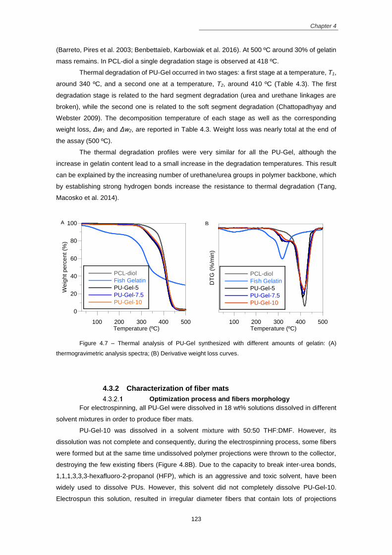
Chapter 4
123
(Barreto, Pires et al. 2003; Benbettaïeb, Karbowiak et al. 2016). At 500 ºC around 30% of gelatin
mass remains. In PCL-diol a single degradation stage is observed at 418 ºC.
Thermal degradation of PU-Gel occurred in two stages: a first stage at a temperature, T1,
around 340 ºC, and a second one at a temperature, T2, around 410 ºC (Table 4.3). The first
degradation stage is related to the hard segment degradation (urea and urethane linkages are
broken), while the second one is related to the soft segment degradation (Chattopadhyay and
Webster 2009). The decomposition temperature of each stage as well as the corresponding
weight loss, Δw1 and Δw2, are reported in Table 4.3. Weight loss was nearly total at the end of
the assay (500 ºC).
The thermal degradation profiles were very similar for all the PU-Gel, although the
increase in gelatin content lead to a small increase in the degradation temperatures. This result
can be explained by the increasing number of urethane/urea groups in polymer backbone, which
by establishing strong hydrogen bonds increase the resistance to thermal degradation (Tang,
Macosko et al. 2014).
Figure 4.7 – Thermal analysis of PU-Gel synthesized with different amounts of gelatin: (A)
thermogravimetric analysis spectra; (B) Derivative weight loss curves.
4.3.2 Characterization of fiber mats
Optimization process and fibers morphology
For electrospinning, all PU-Gel were dissolved in 18 wt% solutions dissolved in different
solvent mixtures in order to produce fiber mats.
PU-Gel-10 was dissolved in a solvent mixture with 50:50 THF:DMF. However, its
dissolution was not complete and consequently, during the electrospinning process, some fibers
were formed but at the same time undissolved polymer projections were thrown to the collector,
destroying the few existing fibers (Figure 4.8B). Due to the capacity to break inter-urea bonds,
1,1,1,3,3,3-hexafluoro-2-propanol (HFP), which is an aggressive and toxic solvent, have been
widely used to dissolve PUs. However, this solvent did not completely dissolve PU-Gel-10.
Electrospun this solution, resulted in irregular diameter fibers that contain lots of projections
0
20
40
60
80
100
100 200 300 400 500
PCL-diol
Fish Gelatin
PU-Gel-5
PU-Gel-7.5
PU-Gel-10
Weig
ht perc
ent (%
)
Temperature (ºC)100 200 300 400 500
PCL-diol
Fish Gelatin
PU-Gel-5
PU-Gel-7.5
PU-Gel-10
DT
G (
%/m
in)
Temperature (ºC)
A B

Chapter 4
124
(Figure 4.9A). As HFP did not improve the PU-Gel-10 solubility, it was not used to dissolve other
PU-Gel due to their toxicity and high cost.
PU-Gel-7.5 solution, prepared from 50:50 THF:DMF mixture, was electrospinnable but
the resulting fibers had a beaded morphology because the dissolution of the polymer was still
incomplete (Figure 4.8C). Even after adjusting the solution concentration and the electrospinning
set-up parameters, the resulting fibers were not free of defects.
When the solution of PU-Gel-5 prepared using a 50:50 THF:DMF mixture was
electrospun, the resulting fibers were produced without defects and with an uniform diameter
(Figure 4.8D).
Figure 4.8 – SEM images of the fibrous mats produced from (A) PU-Gel-10 dissolved in HFP, (B)
PU-Gel-10 dissolved in 50:50 THF:DMF, (C) PU-Gel-7.5 dissolved in 50:50 THF:DMF and (D PU-Gel-5
dissolved in 50:50 THF:DMF.
Other solvent mixtures were tested in order to improve the PU-Gel-5 fibers quality. Those
include: Chloroform:DMF, THF:DMAc and Chloroform:DMAc in a 50:50 proportion. Replacing the
DMF by DMAc, resulted in a fiber mat similar to the one produced using THF:DMF but the fiber’s
diameter is more irregular (Figure 4.9B). Although both DMAc and DMF have high boiling points
and dielectric constants responsible to decrease the viscosity of the solutions, the electrospinning
process was more stable when DMF was used as solvent. When THF was replaced by chloroform
using either DMF or DMAc, projections were thrown to the collector during the electrospinning
process (Figure 4.9C and Figure 4.9D). Solutions with chloroform have higher viscosity and
surface tension than solutions with THF due to the inferior boiling point and dielectric constant.
During the electrospinning, solutions with chloroform clogged in the needle tip, causing the
interruption of the jet and resulting in mats with defects.
The binary solvent mixture of 50:50 THF:DMF is the one used to produce fibrous mats
without defects. Solutions of PU-Gel-5 were prepared with this solvents at 18% w/w concentration
and electrospun at 1.0 mL/h flow rate, 18 kV applied voltage and 20 cm distance from the needle
tip to the collector. The resulting mats have a mean fiber diameter of (705 ± 309) nm.
C D
A B
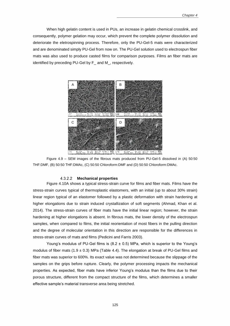
Chapter 4
125
When high gelatin content is used in PUs, an increase in gelatin chemical crosslink, and
consequently, polymer gelation may occur, which prevent the complete polymer dissolution and
deteriorate the eletrospinning process. Therefore, only the PU-Gel-5 mats were characterized
and are denominated simply PU-Gel from now on. The PU-Gel solution used to electrospun fiber
mats was also used to produce casted films for comparison purposes. Films an fiber mats are
identified by preceding PU-Gel by F_ and M_, respectively.
Figure 4.9 – SEM images of the fibrous mats produced from PU-Gel-5 dissolved in (A) 50:50
THF:DMF, (B) 50:50 THF:DMAc, (C) 50:50 Chloroform:DMF and (D) 50:50 Chloroform:DMAc.
Mechanical properties
Figure 4.10A shows a typical stress-strain curve for films and fiber mats. Films have the
stress-strain curves typical of thermoplastic elastomers, with an initial (up to about 30% strain)
linear region typical of an elastomer followed by a plastic deformation with strain hardening at
higher elongations due to strain induced crystallization of soft segments (Ahmad, Khan et al.
2014). The stress-strain curves of fiber mats have the initial linear region; however, the strain
hardening at higher elongations is absent. In fibrous mats, the lower density of the electrospun
samples, when compared to films, the initial reorientation of most fibers in the pulling direction
and the degree of molecular orientation in this direction are responsible for the differences in
stress-strain curves of mats and films (Pedicini and Farris 2003).
Young’s modulus of PU-Gel films is (8.2 ± 0.5) MPa, which is superior to the Young’s
modulus of fiber mats (1.9 ± 0.3) MPa (Table 4.4). The elongation at break of PU-Gel films and
fiber mats was superior to 600%. Its exact value was not determined because the slippage of the
samples on the grips before rupture. Clearly, the polymer processing impacts the mechanical
properties. As expected, fiber mats have inferior Young’s modulus than the films due to their
porous structure, different from the compact structure of the films, which determines a smaller
effective sample’s material transverse area being stretched.
C
A B
D

Chapter 4
126
The hysteresis behavior of the PU-Gel films and fibrous mats was evaluated by subjecting
the samples to 10 cycles of hysteresis. In Figure 4.10B is shown the hysteresis loops and the
percentage of the first hysteresis loop. The first hysteresis loop is the one with superior hysteresis
percentage, which is reduced in the following loops until reach a constant value. This is the typical
behavior of a thermoplastic elastomer. Films have (53 ± 4) % hysteresis, which is superior to the
hysteresis in fibrous mats - (30 ± 6) %. This result is expected because when the fibers are
stretched up to 80 % they did not break, only slippage in order to align in the stretching direction.
Therefore, the fibers can elongate with reduced permanent deformation.
Figure 4.10 – Typical stress-strain curves of PU-Gel films (F_PU-Gel) and fiber mats (M_PU-Gel)
(A) and the respective hysteresis loops (B and C) after 10 cycles stretching and recovery.
XRD analysis
XRD patterns for the PCL, gelatin and PU-Gel films and fibrous mats are presented in
Figure 4.11A. The fitting of the PU-Gel diffractogram was performed by a sum of Voigt functions.
As an example, in Figure 4.11B is shown the fitting of PU-Gel mats. The fitting was also performed
in the diffractograms of the films. XRD diffractogram of PCL have three main peaks at 2θ = 21.4º,
22.0º and 23.7º, which corresponded to the (110), (111) and (200) planes of the crystal structure,
respectively. Other small peaks at 2θ = 15.7º and 24.5º appear due to the diffraction by the (102)
and (201) planes (Ferreira, Gomes et al. 2014). The gelatin showed one wide crystalline reflection
0
2
4
6
8
10
0 100 200 300 400 500 600
F_PU-GelM_PU-Gel
Str
ess (
MP
a)
Strain (%)
0
0,5
1
1,5
2
2,5
3
0 20 40 60 80 100
F_PU-Gel
Str
ess (
MP
a)
Strain (%)
0
0,5
1
1,5
0 20 40 60 80 100
M_PU-Gel
Str
ess (
MP
a)
Strain (%)
A
B C

Chapter 4
127
at 2θ = 20.9º from the triple-helical crystalline structure of collagen renatured in gelatin (Jalaja,
Naskar et al. 2015).
PU-Gel diffractograms display one wide diffraction peak at 2θ = 19º associated with the
amorphous contributions and two small diffraction peaks at 2θ = 21º and 23º from the diffraction
at (110) and (200) crystallographic planes of PCL, respectively. In PU-Gel the diffraction peaks
of PCL are almost absent due to the formation of a rigid network that restricts the organization of
soft segments, decreasing the crystallinity. These results were similar to the ones obtained by
Sarkar et al. (Sarkar, Chourasia et al. 2006) who produced a gelatin based PU using polyethylene
lactate ester diol as soft segment and 2,4-toluene diisocyanate. The intensity of crystalline peaks
is superior in the diffractograms of fibrous mats than in the films. Crystallite size, calculated from
the FWHM of the (110) diffraction peak (Table 4.4), is also higher for the PU-Gel mats, in line with
its higher crystalline degree. Therefore, the reorganization of the PU molecules is affected by the
processing technique. The stretching forces exerted on the polymeric solutions during the
electrospinning process, can induce the molecular chain orientation along the fiber length
(Kongkhlang, Tashiro et al. 2008; Ero-Phillips, Jenkins et al. 2012).
Figure 4.11 – X-ray diffractograms of PU-Gel film and fibrous mat (A). (B) X-ray diffractogram of
PU-Gel fibrous mat (blue), the fitting of their characteristic peaks with Voigt functions (red) and a quadratic
background (green).
Table 4.4 – Results from XRD and tensile tests of PU-Gel films and fibrous mats. Crystalline degree
(wc,x), full width at half maximum of the highest intensity crystalline diffraction peak (FWHW), crystallite size
(tc), Young modulus (Y), elongation at break (Ɛr) and tensile stress at 600% strain (σ600).
Films/Fibrous
Mats
XRD Mechanical tests
wc,x (%) FWHW (º) tc (nm) Y (MPa) Ɛr (%) σ600 (MPa)
F_PU-Gel 0.77 ± 0.06 0.101 79.0 8.2 ± 0.5 >600 9.9 ± 0.6
M_PU-Gel 1.96 ± 0.12 0.0003 >100 1.9 ± 0.3 >600 5.3 ± 0.3
5 10 15 20 25 30 35
F_PU-Gel
M_PU-Gel
Gelatin
PCL-diol
Inte
nsity
2degrees)
16 18 20 22 24 26 28
Inte
nsity
A B

Chapter 4
128
Wettability
The contact angle measurements on PU-Gel films and mats, as well as the images of the
water drop in contact with the film and mat surface is represented in Figure 4.12. The WCA of the
fiber mats and films is (145 ± 3) º and (108 ± 3) º, respectively, indicating the hydrophobicity (WCA
> 90º) of the sample’s’ surface. The presence of gelatin in PUs should reduce the hydrophobicity
of the samples. Kim et al. (Kim, Heo et al. 2009) produced fibrous mats from blends of hydrophilic
gelatin and hydrophobic PU, which have inferior WCA when compared to mats produced using
just PU. However, in our work the presence of gelatin is not the determinant factor affecting the
WCA values. The high WCA obtained for PU-Gel samples is probably related to the extensive
crosslink that occurred when the gelatin was incorporated into the PU backbone, preventing the
wetting and spreading of the liquid molecules over the films and mats. Similar results were
observed for films obtained from isocyanate-terminated PU grafted onto chitosan molecules (Lee,
Kwon et al. 2014; Mahanta, Mittal et al. 2015), where WCA increases with increment of CS
ceosslinking density.
The surface of the fiber mats, different from the films, influence the WCA measurements.
The higher surface roughness and porosity of the fibers can lead to the entrapment of air bubbles
at the water-fiber interface, leaving less contact area for water, which may be responsible for the
superior WCA values observed in the fibrous mats (Tijing, Park et al. 2013).
Figure 4.12 – Water contact angle values of the PU-Gel films and electrospun fibrous mats and the
respective water drop images.
Degradation profile
Figure 4.13A and Figure 4.13B shows the degradation profile of PU-Gel films and fibrous
mats, respectively, when immersed in PBS, lipase and trypsin solution. In PBS solution, PU-Gel
films and fibrous mats barely lose weight during 37 days.
Lipase is an esterase that catalyzes the hydrolysis of the PCL soft segment ester
linkages, resulting in α-hydroxyacids degradation products and urethane and urea fragments
(Tokiwa, Ando et al. 1990; He and Chu 2013). In lipase solution, the films degraded at a constant
rate during 37 days, losing (7.2 ± 0.5) % of their initial weight. On the opposite, mats lost 15% of
their weight in the first two weeks and only 3.5% of their weight in the following 3 weeks. The
100
110
120
130
140
150
160
170
F_PU-Gel M_PU-Gel
WC
A (
°)
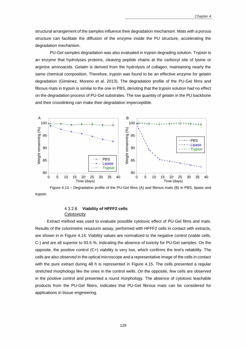
Chapter 4
129
structural arrangement of the samples influence their degradation mechanism. Mats with a porous
structure can facilitate the diffusion of the enzyme inside the PU structure, accelerating the
degradation mechanism.
PU-Gel samples degradation was also evaluated in trypsin degrading solution. Trypsin is
an enzyme that hydrolyses proteins, cleaving peptide chains at the carboxyl site of lysine or
arginine aminoacids. Gelatin is derived from the hydrolysis of collagen, maintaining nearly the
same chemical composition. Therefore, trypsin was found to be an effective enzyme for gelatin
degradation (Giménez, Moreno et al. 2013). The degradation profile of the PU-Gel films and
fibrous mats in trypsin is similar to the one in PBS, denoting that the trypsin solution had no effect
on the degradation process of PU-Gel substrates. The low quantity of gelatin in the PU backbone
and their crosslinking can make their degradation imperceptible.
Figure 4.13 – Degradation profile of the PU-Gel films (A) and fibrous mats (B) in PBS, lipase and
trypsin.
Viability of HFFF2 cells
Cytotoxicity
Extract method was used to evaluate possible cytotoxic effect of PU-Gel films and mats.
Results of the colorimetric resazurin assay, performed with HFFF2 cells in contact with extracts,
are shown in in Figure 4.14. Viability values are normalized to the negative control (viable cells,
C-) and are all superior to 93.5 %, indicating the absence of toxicity for PU-Gel samples. On the
opposite, the positive control (C+) viability is very low, which confirms the test’s reliability. The
cells are also observed in the optical microscope and a representative image of the cells in contact
with the pure extract during 48 h is represented in Figure 4.15. The cells presented a regular
stretched morphology like the ones in the control wells. On the opposite, few cells are observed
in the positive control and presented a round morphology. The absence of cytotoxic leachable
products from the PU-Gel fibers, indicates that PU-Gel fibrous mats can be considered for
applications in tissue engineering.
80
85
90
95
100
0 5 10 15 20 25 30 35 40
PBS
Lipase
Trypsin
Weig
ht re
main
nin
g (
%)
Time (days)
80
85
90
95
100
0 5 10 15 20 25 30 35 40
PBS
Lipase
Trypsin
Weig
ht re
main
nin
g (
%)
Time (days)
A B

Chapter 4
130
Figure 4.14 – Cytotoxicity assessment of HFFF2 cells cultured with extracts from PU-Gel films and
mats at concentrations of 15, 10, and 5 mg/mL. Positive and negative controls have culture medium with
and without 10% DMSO, respectively.
Figure 4.15 – Optical microscope images of the HFFF2 cells seeded in 96 well plate in contact with
pure extracts of PU- Gel films (A) and fiber mats (B), negative control (live cells) (C) and positive control
(dead cells) (D). Scale bar: 200 µm.
Adhesion and proliferation assay
Figure 4.16A displays the viability of HFF2 cells seeded on PU-Gel films, PU-Gel fibrous
mats and TCP wells (cell control, CC), which was accessed using the resazurin test. Cell adhesion
was evaluated 24 h after cell seeding (day 1) and cell proliferation was evaluated on subsequent
days up to 11 days in culture.
On the first day, and in comparison to CC, cell adhesion on fibrous mats is significantly
inferior while cell adhesion on films has no statistically difference. Following day 1, the cells on
fibrous mats increase their proliferation over time but never reach the CC population. However,
cells on films grow similar to CC up to day 5, and then cell population remains constant until the
end of the assay. Fibrous mats are suitable substrates for cell adhesion and proliferation due to
their fibrillar structure similar to the ECM, their high surface area and their 3D structure that allow
the exchange of nutrients and toxic products conferring the cells with the appropriate environment
and maintain their metabolism (Cui, Zhou et al. 2016).
0
20
40
60
80
100
F_PU-Gel M_PU-Gel
15 mg/mL
10 mg/mL
5 mg/mL
Negative Control
Positive ControlVia
bili
ty (
%)

Chapter 4
131
Figure 4.16 – (A) Proliferation of HFFF2 cells seeded on the PU-Gel films and fiber mats after 1, 3,
5, 7, 9 and 11 days of culture (mean ± standard deviation, n=5). Significance: *p<0.05. Fluorescent images
of phalloidin (red) and DAPI (blue) stained HFFF2 cells seeded on (B) PU-Gel films, (C) PU-Gel fibrous mats
and (D) glass coverslips, after 5 days in culture. Scale bar: 100 µm.
Fluorescent images of cells after 5 days in culture on films, fibrous mats and glass
coverslips are shown in Figure 4.16. The higher projected cell area is observed on the flat
substrates where cells protruded over all directions with noticeable stress fiber formation. On the
mats, the cells exhibited longer and thin filaments with inferior projected area. PU-Gel fibers, with
an average diameter of 705 nm, can limit the size of the focal adhesions and limit cell spreading.
Similar results were reported by Bashur et al. (Bashur, Dahlgren et al. 2006). In his work,
fibroblasts grown on PLLA mats with diameters similar to the ones of the PU-Gel mats, have
reduced cell area. The limitation in cell spreading on the mats can explain the inferior adhesion
and proliferation of the fibroblasts in the initial days, where they are adapting to the new
environment.
4.3.3 Random vs Aligned fibrous mats
Fibrous mats morpholgy
PU-Gel solutions at 18 wt% concentration in 50:50 THF:DMF solvents was electrospun
to create non-woven fibrous structures. Random mats were collected in a flat collector while
aligned mats were collected in a rotatory mandrel. In Figure 4.17 is shown the SEM images of the
PU-Gel fibrous mats with random and aligned fibers as well as the fiber diameter distributions.
Both fibrous mats were produced without defects. In random mats, the fibers have an average
* *
* *
* *
* *
*
* *
* * *
*
0
1
2
3
4
5
6
7
Day 1 Day 3 Day 5 Day 7 Day 9 Day 11
F_PU-Gel
M_PU-Gel
CC
Ab
so
rba
nce
A
B C D

Chapter 4
132
diameter of (705 ± 309) nm while aligned mats have superior average diameter, (816±416) nm.
The alignment degree was obtained by analyzing the SEM images on ImageJ software using the
preferred angle plugin with the Fast Fourier Transform (FFT) and the oval projection method. The
direct measurement of the angle of the fibers with the horizontal (0º) was performed to get the
fiber angular distribution. Both the FFT intensity graph as well as the angular distribution
histogram are represented in Figure 4.17C and Figure 4.17F, respectively. From the fiber angular
distribution analysis, in the aligned mats 96% of the fibers are within the range of 60º to 120º with
respect to the 90º. On the opposite, in random mats the fibers were deposited in all directions
without any preferential orientation. From the analysis of the shape and weight of the peaks at
the FFT intensity graph in aligned mats, few and high intense peaks were observed. Thus,
confirming ordered fibers in the mats (Ayres, Bowlin et al. 2006). On the opposite, FFT intensity
graph of random mats shows multiple peaks with small intensities, indicating fibers with poor order
in the mats.
Figure 4.17 – SEM images of random (A) and aligned (D) PU-Gel fibrous mats, and the respective
histograms of the fiber diameter distribution (B and E) and the angle distribution (C and F).
Mechanical properties
In Figure 4.18 is shown the representative stress-strain curves of aligned and random
PU-Gel mats. The Young’s modulus of the random mats is (5.19 ± 0.08) MPa, which is inferior to
the one of the aligned mats that is (17 ± 2) MPa. On the opposite, random mats can withstand a
maximum elongation at break of (713 ± 13) %, which is superior to the elongation at break of
aligned mats that is (419 ± 25) %. Aligned fibers can withstand superior loads but with inferior
elongations (Yao, Bastiaansen et al. 2014). In the aligned fibers, as the mechanical load is applied
in the direction of the fiber alignment, the aligned fibers are already stretched. Thus, aligned mats
A B C
E F D
0 30 60 90 120 150 1800
10
20
30
40
50
60
70
Nu
mbe
r o
f fib
ers
Angle with X-axis (º)
Inte
nsity
0 0.5 1 1.5 2
Fre
quency
Fiber Diameter Range (m)
0 30 60 90 120 150 180
0
10
20
30
40
50
60
70
Num
ber
of fibe
rs
Angle with X-axis (º)
Inte
nsity
0 0.5 1 1.5 2
Fre
quency
Fiber Diameter Range (m)

Chapter 4
133
did not organize in the stretching direction as the randomly oriented fibers do, resulting in inferior
elongations.
Figure 4.18 – Stress-strain curves of the random (R_) and aligned (A_) PU-Gel fibrous mats.
Wettability
Figure 4.19 displays the WCA values of the random and aligned PU-Gel mats and the
respective sessile drop picture in contact with the substrate. The WCA values for the PU-Gel
fibrous mats in random and aligned morphology are (145 ± 3) º and (143 ± 3) º, respectively. Both
mats are hydrophobic and their WCA values very similar. The WCA depends on the morphology
of the fibrous mats such as, the alignment degree, the fiber diameter and the porosity and pore
size. Inferior WCA has been reported in fibrous mats with aligned morphology (Kim, Hwang et al.
2016) and in mats with superior pore size and diameter (Cui, Li et al. 2008). In PU-Gel mats, the
alignment degree did not affect the WCA measurements. Probably, other factors such as the
surface chemistry have superior influence in the WCA measurements.
Figure 4.19 – Water contact angle values of random and aligned PU-Gel mats.
Cellular assays
The biocompatibility of the HFFF2 cells seeded on random and aligned PU-Gel mats was
evaluated using the rezasurin calorimetric assay over 11 days. Figure 4.20A shows the results of
0
2
4
6
8
10
0 100 200 300 400 500 600
R_PU-Gel
A_PU-Gel
Str
ess (
MP
a)
Strain (%)
100
110
120
130
140
150
160
170
R_PU-Gel A_PU-Gel
WC
A (
°)

Chapter 4
134
cell population over time for the random and aligned PU-Gel mats as well as for the tissue culture
plate (TCP) wells (cell control,CC). In comparison to CC, cell adhesion (evaluated after 24 h of
cell seeding) to aligned mats has no statistically significant difference while adhesion to random
mats is slightly inferior. On the following days, cell population remains inferior in random mats
when compared to aligned mats and CC, which has similar cell population values on the following
days.
Other studies reported better proliferation of mesenchymal stem cells (Chang, Fujita et
al. 2013; Zandén, Erkenstam et al. 2014) and neural stem cells (Kim, Hwang et al. 2016), on
fibrous mats with aligned morphology. One explanation for that is the similarity of the aligned
fibrous substrate with the flat controls, which provide more contact points for cell adhesion and
proliferation. However, in a study of Jamadi et al. (Jamadi, Ghasemi-Mobarakeh et al. 2016) the
proliferation of cardiomyocytes was reduced on the aligned fibrous mats of PUs blended with
gelatin. For 3T3 cell line, no differences in cell adhesion and proliferation on random and aligned
PCL and gelatin composite electrospun mats were observed (Fee, Surianarayanan et al. 2016).
Although the direct comparison of the studies is difficult to perform due to the different cell types
and different materials, all the studies agreed that the anisotropic mats are good to cellular
guidance.
Figure 4.20 – Proliferation assay of HFFF2 cells seeded on the electrospun PU-Gel fibrous mats
with random and aligned morphology every other day during 11 days of culture (mean ± standard deviation,
n=5) (A) Significance: *p<0.05. Fluorescent images of phalloidin (red) and DAPI (blue) stained HFFF2 cells
in the (B) random PU-Gel mats, (C) aligned PU-Gel mats and (D) glass coverslips, after 5 days in culture.
Scale bar: 100 µm.
0
1
2
3
4
5
6
Day 1 Day 3 Day 5 Day 7 Day 9 Day 11
R_PU-Gel
A_PU-Gel
CC
Absorb
ance
*
*
*
*
* *
*
*
* A
B C D

Chapter 4
135
Fluorescent images of cells after 5 days in culture on different substrates is shown in
Figure 4.20B, C and D. On the control, cells are well spread with high projected area. On the
opposite, cells stretched and elongated on the mats. On the aligned mats, the cell’s cytoskeleton
followed the fiber alignment as well as the cell’s nuclei. In addition, the cells grew on bundles that
can establish cell-cell contacts between them.
4.4 Conclusion In this chapter it was described the synthesis and characterization of gelatin based PUs
and their processing into fibrous mats using the electrospinnig technique.
PUs based on PCL-diol and gelatin in different Gel/PCL-diol weight proportions (5%, 7.5%
and 10%) were synthesized. However, only the PU-Gel with inferior gelatin content (5%) rendered
fibrous mats with uniform fiber diameter and without defects, when electrospun. Fibrous mats
have a lower Young’s modulus and a higher crystallinity, are more hydrophobic and degrade
faster in lipase solution when compared to the corresponding films. The fibrous structure support
the adhesion and proliferation of HFFF2 cells.
Aligned mats produced using a rotating mandrel have superior Young’s modulus and
reduced elongation at break in the direction of fiber alignment, and support superior adhesion and
proliferation of HFFF2 cells when compared to the random mats. In addition, aligned mats guide
cell in the direction of fiber’s alignment. Thus, PU-Gel mats can offer mechanical and chemical
support as well as guidance cues for fibroblasts, which is an indicator of their suitable application
in soft tissue engineering.
4.5 References Ahmad, N., M. Khan, et al. (2014). "The influence of cross-linking/chain extension structures on mechanical properties of htpb-based polyurethane elastomers." Arabian Journal for Science and Engineering 39(1): 43-
51. Amadori, S., P. Torricelli, et al. (2015). "Effect of sterilization and crosslinking on gelatin films." Journal of Materials Science: Materials in Medicine 26(2): 1-9.
Ayres, C., G. L. Bowlin, et al. (2006). "Modulation of anisotropy in electrospun tissue-engineering scaffolds: analysis of fiber alignment by the fast Fourier transform." Biomaterials 27(32): 5524-5534.
Barikani, M., H. Honarkar, et al. (2009). "Synthesis and characterization of polyurethane elastomers based on chitosan and poly (ε‐caprolactone)." Journal of Applied Polymer Science 112(5): 3157-3165.
Barreto, P., A. Pires, et al. (2003). "Thermal degradation of edible films based on milk proteins and gelatin in inert atmosphere." Polymer Degradation and Stability 79(1): 147-152.
Bashur, C. A., L. A. Dahlgren, et al. (2006). "Effect of fiber diameter and orientation on fibroblast morphology and proliferation on electrospun poly (D, L-lactic-co-glycolic acid) meshes." Biomaterials 27(33): 5681-5688.
Benbettaïeb, N., T. Karbowiak, et al. (2016). "Impact of electron beam irradiation on fish gelatin film properties." Food chemistry 195: 11-18.
Chan-Chan, L., C. Tkaczyk, et al. (2013). "Characterization and biocompatibility studies of new degradable poly (urea) urethanes prepared with arginine, glycine or aspartic acid as chain extenders." Journal of Materials Science: Materials in Medicine 24(7): 1733-1744.
Chang, J.-C., S. Fujita, et al. (2013). "Cell orientation and regulation of cell–cell communication in human mesenchymal stem cells on different patterns of electrospun fibers." Biomedical Materials 8(5): 055002.

Chapter 4
136
Chattopadhyay, D. and D. C. Webster (2009). "Thermal stability and flame retardancy of polyurethanes." Progress in Polymer Science 34(10): 1068-1133.
Chuaynukul, K., T. Prodpran, et al. (2014). "Preparation, thermal properties and characteristics of gelatin molding compound resin." Research Journal of Chemical & Environmental Sciences 2(4): 01-09.
Cui, W., X. Li, et al. (2008). "Degradation patterns and surface wettability of electrospun fibrous mats." Polymer Degradation and Stability 93(3): 731-738.
Cui, W., Y. Zhou, et al. (2016). "Electrospun nanofibrous materials for tissue engineering and drug delivery." Science and Technology of Advanced Materials 11(1): 014108.
Ero-Phillips, O., M. Jenkins, et al. (2012). "Tailoring crystallinity of electrospun plla fibres by control of electrospinning parameters." Polymers 4(3): 1331-1348.
Fee, T., S. Surianarayanan, et al. (2016). "Nanofiber Alignment Regulates NIH3T3 Cell Orientation and Cytoskeletal Gene Expression on Electrospun PCL+ Gelatin Nanofibers." PLoS ONE 11(5): e0154806.
Ferreira, J. L., S. Gomes, et al. (2014). "Electrospinning polycaprolactone dissolved in glacial acetic acid: Fiber production, nonwoven characterization, and In Vitro evaluation." Journal of Applied Polymer Science 131(22): 41068.
Garrett, J. T., R. Xu, et al. (2003). "Phase separation of diamine chain-extended poly (urethane) copolymers: FTIR spectroscopy and phase transitions." Polymer 44(9): 2711-2719.
Giménez, B., S. Moreno, et al. (2013). "Antioxidant properties of green tea extract incorporated to fish gelatin films after simulated gastrointestinal enzymatic digestion." LWT-Food Science and Technology 53(2): 445-
451. Guan, J., K. L. Fujimoto, et al. (2005). "Preparation and characterization of highly porous, biodegradable polyurethane scaffolds for soft tissue applications." Biomaterials 26(18): 3961-3971.
Hafeman, A. E., K. J. Zienkiewicz, et al. (2011). "Characterization of the degradation mechanisms of lysine-derived aliphatic poly (ester urethane) scaffolds." Biomaterials 32(2): 419-429.
He, M. and C.-C. Chu (2013). "A new family of functional biodegradable arginine-based polyester urea urethanes: Synthesis, chracterization and biodegradation." Polymer 54(16): 4112-4125.
Henriques, C., R. Vidinha, et al. (2009). "A systematic study of solution and processing parameters on nanofiber morphology using a new electrospinning apparatus." Journal of nanoscience and nanotechnology 9(6): 3535-3545.
Hu, X., D. Li, et al. (2011). "Biological hydrogel synthesized from hyaluronic acid, gelatin and chondroitin sulfate by click chemistry." Acta biomaterialia 7(4): 1618-1626.
Jalaja, K., D. Naskar, et al. (2015). "Fabrication of cationized gelatin nanofibers by electrospinning for tissue regeneration." Rsc Advances 5(109): 89521-89530.
Jamadi, E. S., L. Ghasemi-Mobarakeh, et al. (2016). "Synthesis of polyester urethane urea and fabrication of elastomeric nanofibrous scaffolds for myocardial regeneration." Materials Science and Engineering: C 63:
106-116. Kang, H.-W., Y. Tabata, et al. (1999). "Fabrication of porous gelatin scaffolds for tissue engineering." Biomaterials 20(14): 1339-1344.
Kim, J. I., T. I. Hwang, et al. (2016). "A Controlled Design of Aligned and Random Nanofibers for 3D Bi-functionalized Nerve Conduits Fabricated via a Novel Electrospinning Set-up." Scientific reports 6.
Kim, S. E., D. N. Heo, et al. (2009). "Electrospun gelatin/polyurethane blended nanofibers for wound healing." Biomedical Materials 4(4): 044106.
Kongkhlang, T., K. Tashiro, et al. (2008). "Electrospinning as a new technique to control the crystal morphology and molecular orientation of polyoxymethylene nanofibers." Journal of the American Chemical Society 130(46): 15460-15466.
Kucińska-Lipka, J., I. Gubańska, et al. (2013). "Gelatin-modified polyurethanes for soft tissue scaffold." The Scientific World Journal 2013: 450132.

Chapter 4
137
Labow, R. S., E. Meek, et al. (1999). "The biodegradation of poly (urethane) s by the esterolytic activity of serine proteases and oxidative enzyme systems." Journal of Biomaterials Science, Polymer Edition 10(7):
699-713. Lee, T., S. Kwon, et al. (2014). "Biodegradable sol–gel coatings of waterborne polyurethane/gelatin chemical hybrids." Progress in Organic Coatings 77(6): 1111-1116.
Li, G., D. Li, et al. (2013). "Alternating block polyurethanes based on PCL and PEG as potential nerve regeneration materials." Journal of Biomedical Materials Research Part A 102(3): 685-697.
Li, S., X. Kong, et al. (2015). "Preparation of uniform poly (urea–siloxane) microspheres through precipitation polymerization." RSC Advances 5(110): 90313-90320.
Li, S., J. Zhao, et al. (2014). "Synthesis and characterization of aliphatic segmented poly (ether amide urethane) s through a non-isocyanate route." RSC Advances 4(45): 23720-23729.
Liu, H., W. Xu, et al. (2010). "Silk‐inspired polyurethane containing GlyAlaGlyAla tetrapeptide. I. Synthesis and primary structure." Journal of applied polymer science 117(1): 235-242.
Mahanta, A. K., V. Mittal, et al. (2015). "Polyurethane-grafted chitosan as new biomaterials for controlled drug delivery." Macromolecules 48(8): 2654-2666.
Mandalari, G., R. M. Faulks, et al. (2008). "Release of protein, lipid, and vitamin E from almond seeds during digestion." Journal of Agricultural and Food Chemistry 56(9): 3409-3416.
Oprea, S. (2010). "The effect of chain extenders structure on properties of new polyurethane elastomers." Polymer bulletin 65(8): 753-766.
Parrag, I. C. and K. A. Woodhouse (2010). "Development of biodegradable polyurethane scaffolds using amino acid and dipeptide-based chain extenders for soft tissue engineering." Journal of Biomaterials Science, Polymer Edition 21(6-7): 843-862.
Pedicini, A. and R. J. Farris (2003). "Mechanical behavior of electrospun polyurethane." Polymer 44(22):
6857-6862. Perales-Alcacio, J., J. Santa-Olalla Tapia, et al. (2013). "HUVEC biocompatibility and platelet activation of segmented polyurethanes prepared with either glutathione or its amino acids as chain extenders." Journal of Biomaterials Science, Polymer Edition 24(14): 1601-1617.
Rockwood, D. N., R. E. Akins, et al. (2008). "Culture on electrospun polyurethane scaffolds decreases atrial natriuretic peptide expression by cardiomyocytes in vitro." Biomaterials 29(36): 4783-4791.
Rockwood, D. N., K. A. Woodhouse, et al. (2007). "Characterization of biodegradable polyurethane microfibers for tissue engineering." Journal of Biomaterials Science, Polymer Edition 18(6): 743-758.
Sarkar, D., J. C. Yang, et al. (2008). "Structure‐property relationship of L‐tyrosine‐based polyurethanes for biomaterial applications." Journal of Applied Polymer Science 108(4): 2345-2355.
Sarkar, S., A. Chourasia, et al. (2006). "Synthesis and characterization of gelatin based polyester urethane scaffold." Bulletin of Materials Science 29(5): 475-484.
Shah, P. N., R. L. Manthe, et al. (2009). "Electrospinning of L-tyrosine polyurethanes for potential biomedical applications." Polymer 50(10): 2281-2289.
Sheth, J. P., G. L. Wilkes, et al. (2005). "Probing the hard segment phase connectivity and percolation in model segmented poly (urethane urea) copolymers." Macromolecules 38(13): 5681-5685.
Shi, Y., X. Zhan, et al. (2008). "Quantitative IR characterization of urea groups in waterborne polyurethanes." Journal of Polymer Science Part A: Polymer Chemistry 46(7): 2433-2444.
Skarja, G. and K. Woodhouse (2000). "Structure‐property relationships of degradable polyurethane elastomers containing an amino acid‐based chain extender." Journal of Applied Polymer Science 75(12):
1522-1534. Tang, D., C. W. Macosko, et al. (2014). "Thermoplastic polyurethane elastomers from bio-based poly (δ-decalactone) diols." Polymer Chemistry 5(9): 3231-3237.

Chapter 4
138
Tatai, L., T. G. Moore, et al. (2007). "Thermoplastic biodegradable polyurethanes: The effect of chain extender structure on properties and in-vitro degradation." Biomaterials 28(36): 5407-5417.
Tijing, L. D., C.-H. Park, et al. (2013). "Characterization and mechanical performance comparison of multiwalled carbon nanotube/polyurethane composites fabricated by electrospinning and solution casting." Composites Part B: Engineering 44(1): 613-619.
Tokiwa, Y., T. Ando, et al. (1990). "Biodegradation of synthetic polymers containing ester bonds." Polym. Mater. Sci. Eng 62: 988-992.
Vatankhah, E., M. P. Prabhakaran, et al. (2014). "Phenotypic modulation of smooth muscle cells by chemical and mechanical cues of electrospun Tecophilic/gelatin nanofibers." ACS applied materials & interfaces 6(6):
4089-4101. Wang, F., Z. Zheng, et al. (2014). "Trypsin-inspired poly (urea-urethane) s containing phenylalanine-lysine ethyl ester-phenylalanine units." Polymer Degradation and Stability 100: 86-92.
Yao, J., C. W. Bastiaansen, et al. (2014). "High strength and high modulus electrospun nanofibers." Fibers 2(2): 158-186.
Yilgor, I., E. Yilgor, et al. (2006). "FTIR investigation of the influence of diisocyanate symmetry on the morphology development in model segmented polyurethanes." Polymer 47(11): 4105-4114.
Zandén, C., N. H. Erkenstam, et al. (2014). "Stem cell responses to plasma surface modified electrospun polyurethane scaffolds." Nanomedicine: Nanotechnology, Biology and Medicine 10(5): 949-958.
Zhang, S., L. Cheng, et al. (2003). "NMR studies of water-borne polyurethanes." Journal of applied polymer science 90(1): 257-260.
Zhang, Y., W. He, et al. (2017). "Gemini quaternary ammonium salt waterborne biodegradable polyurethanes with antibacterial and biocompatible properties." Materials Chemistry Frontiers 1(2): 361-368.
Zia, K. M., M. Barikani, et al. (2008). "Molecular engineering of chitin based polyurethane elastomers." Carbohydrate Polymers 74(2): 149-158.
Zou, J., Y. Chen, et al. (2015). "Effect of hard segments on the thermal and mechanical properties of water blown semi-rigid polyurethane foams." Journal of Polymer Research 22(6): 1-10.
Chapter 5
Biocompatibility evaluation of electrospun mats
from chitosan or gelatin based poly(urethane
urea)

Chapter 5
140
5. Biocompatibility evaluation of electrospun mats from
chitosan or gelatin based poly(urethane urea)
5.1 Introduction
Stem cells from adult or embryonic origin as well as the induced pluripotent stem cells
have the ability to proliferate indefinitely and to differentiate into different lineages, replacing the
damaged or dead cells in adults (Watt and Driskell 2010). Therefore, stem cells arise as valuable
cell sources for regenerative medicine. While embryonic stem cells are pluripotent cells
differentiating into any of the three germ layers, the somatic stem cells are able to self-renewal
and differentiate into all the cells of the originating organ. The progress on adult stem cells has
been faster and less problematic than on embryonic stem cells due to the absence of ethical
issues and lower risk of in vivo teratoma formation (Trounson and McDonald 2015).
Though the widespread study of the stem cells, their application in regenerative medicine
is still limited. One of the problems that stem cell transplantation is facing is their low survival rate
due to the inhospitable environment inside the lesions/injuries. Further, the differentiation of
survivors’ stem cells was uncontrolled in the hostile site. One reason for that is the absence of a
physical substrate to support and control the stem cell behavior (Watt and Huck 2013;
Zweckberger, Ahuja et al. 2016). In the body, the stem cells are located into specific
microenvironments, called niches, which are responsible for the regulation of stem cell behavior
(Scadden 2006). The niche has in their constitution the stem cells, supporting cells, soluble
biomolecules and the extracellular matrix (ECM). The ECM is much more than the physical
support of the stem cells, it provides cues to control the stem cell behavior, influencing their fate
(Watt and Huck 2013). Therefore, supporting scaffolds that provide topographical and biological
cues are required to increase the stem cell survival and to regulate their functions.
Scaffolds produced by the electrospinning technique are meshes of sub-micrometric
fibers that resemble the ECM. Characteristics such as fiber diameter and alignment degree can
be easily controlled to regulate the stem cell behavior (Christopherson, Song et al. 2009). Such
structures support the adhesion, proliferation, growth and differentiation of cells due to the high
surface to volume ratio of the fibers, providing higher contact points for cell attachment as well as
allowing the exchange of nutrients and waste products essential for cell survival, see recent
review (Jiang, Carbone et al. 2015).
Polyurethanes (PUs) are segmented polymers constituted by a polyol, an isocyanate and
a chain extender (a low molecular weight diol or diamine). They are widely used in several
applications in the medical field due to their high stability and suitability for long-term applications
(Zdrahala and Zdrahala 1999). Much attention has been devoted to the PUs during the last years
as polymers with tunable physico-chemical properties obtained by changing their constituents.
Therefore, PUs can be synthetized to be biocompatible, biodegradable and with mechanical
properties adjustable for different tissue engineering applications. In order to do that, natural
polymers such as chitosan (Barikani, Honarkar et al. 2009) and gelatin (Lee, Kwon et al. 2014) or

Chapter 5
141
aminoacids such as glycine, arginine and aspartic acid (Skarja and Woodhouse 2000; Chan-
Chan, Tkaczyk et al. 2013) have been incorporated in the PU structure as chain extenders.
PUs can be dissolved in organic solvents to be processed by the electrospinning,
rendering fibrous substrates for stem cell support. However, PUs extended with natural polymers
have not been processed with the electrospinning technique. Usually, the PUs were blended with
natural polymers and electrospun to render fibrous mats with motifs for cell adhesion. Examples
of these polymers are collagen (Jia, Prabhakaran et al. 2014), ethyl cellulose (Chen, Liao et al.
2015), gelatin (Vatankhah, Prabhakaran et al. 2014), and mixtures of collagen and chitosan
(Huang, Chen et al. 2011) or collagen and elastin (Wong, Liu et al. 2013). Furthermore, the
electrospun PU mats were usually coated with adhesion proteins such as poly-D-lysine
(Puschmann, de Pablo et al. 2014) to promote neuronal cells adhesion and fibronectin, to provide
a better environment for mesenchymal stem cells (MSCs) (Bashur, Shaffer et al. 2009; Cardwell,
Dahlgren et al. 2012).
In this chapter was produced sub-micrometric fibrous scaffolds with random and aligned
morphology, through the electrospinning technique, from PU extended with either chitosan (PU-
CS) or gelatin (PU-Gel). Chitosan and gelatin are biocompatible and biodegradable natural
polymers widely used in tissue engineering and their incorporation in the PU structure provide
better cellular adhesion, as previously described. The resulting mats were characterized
according to the morphology, mechanical properties and wettability. The biocompatibility of the
polymeric fibers was evaluated using the 3T3 cell line (fibroblasts) and two types of stem cells:
human MSCs and human neural stem cells (NSCs). The mats were not coated with adhesion
proteins in order to monitor the influence of the physical and chemical properties of the mats to
the cells.
5.2 Materials and methods
5.2.1 Materials
PU-CS and PU-Gel were synthetized as described in chapter 3 and 4, respectively. The
PUs have in their constitution polycaprolactone-diol (PCL-diol, Mn=2000, Acros Organics) as soft
segment, isophorone diisocyanate (IPDI, Huls) and chitosan (Mw=26kDa – depolimerization with
NaNO2, Cognis S) or gelatin (from cold water fish skin, Sigma-Aldrich) as chain extenders,
resulting in PU-CS and PU-Gel, respectively. N,N-Dimethylformamide (DMF) and
Tetrahydrophuran (THF) were purchased from Carlo Erba and used as received.
For 3T3 cultivation, Dulbecco’s modified Eagle’s medium (DMEM/F12; Gibco, Thermo
Fisher Scientific; Waltham, MAA, USA), fetal bovine serum (InvivoGen; San Diego, CA, USA),
trypsin/ethylenediaminetetraacetic acid (EDTA) solution (Life Technologies; Prague, Czech
Republic), gentamicin (Sandoz - Novartis company) and resazurin (Sigma-Aldrich) were used.
For MSCs cultivation, alpha-minimum essential medium (MEM; EastPort; Prague, Czech
Republic), platelet lysate (PL; IKEM; Prague, Czech Republic),
trypsin/ethylenediaminetetraacetic acid (EDTA) solution (Life Technologies; Prague, Czech
Republic), gentamicin (Sandoz - Novartis company) and resazurin (Sigma-Aldrich) were used.

Chapter 5
142
For SPC-01 (a neural stem cell line derived from human fetal spinal cord tissue)
cultivation the following reagents were used: Dulbecco’s modified Eagle’s medium (DMEM/F12;
Gibco, Thermo Fisher Scientific; Waltham, MAA, USA), human serum albumin (Baxter
Healthcare; Norfolk, UK), L-glutamine, human apo-transferrin, putrescine dichloride, human
recombinant insulin, progesterone, sodium selenite, 4-hydroxytamoxifen (OHT), laminin (Sigma-
Aldrich), human epidermal growth factor (EGF), human fibroblast growth factor (bFGF;
PeproTech; London, UK), primocin (InvivoGen; San Diego, CA, USA), TrypZean (Lonza; Basel,
Switzerland) and WST-1 [2-(2-methoxy-4-nitrophenyl)-3-(4-nitrophenyl)-5-(2,4-disulfophenyl)-
2H-tetrazolium, monosodium salt] from Roche (Mannheim, Germany).
Chemiblocker, Triton X-100, goat serum, Alexa-Fluor 568 phalloidin, GAM Alexa-Fluor
594, 4, 6-diamidino-2-phenylindole dihydrochloride (DAPI), mouse antineurofilament 70 kDa
(clone DA2) antibody (Merck Millipore; Prague, Czech Republic), mouse antihuman MAP2
antibody (Chemicon, Merck Millipore, Prague, Czech Republic) and Aqua Popy/Mount
(Polysciences, Inc.; Prague, Czech Republic) were used for fluorescent staining.
5.2.2 Characterization of polyurethanes
Fourier Transform Infrared Spectroscopy
Fourier transform infrared spectroscopy (FTIR) was used to identify the structure of the
PUs. IR spectra were recorded with a spectrometer FT-IR Nicolet 6700, from Thermo Electron
Corporation, in ATR (attenuated total reflectance) mode with a resolution of 4 cm-1.
5.2.3 Production of fibrous mats
PU-CS at 18% (w/w) and PU-Gel at 13% (w/w) were dissolved in DMF:THF 50:50 (w/w)
under magnetic stir overnight. The prepared solutions were fed on a 5 mL plastic syringe
connected to a 21G stainless steel blunt needle (internal diameter of 0.508 nm) using a syringe
pump (SyringePump NE-300) programmed with a flow rate of 1.0 mL/h. A high voltage of 13 kV
and 15 kV was applied to the needle, for the PU-CS and PU-Gel solutions, respectively, with a
high voltage power supply (Power Supply – iseg T1CP300º340p), while an aluminum plate, at a
distance of 20 cm from the needle tip, was kept grounded to collect the fibers. Aligned fibers were
collected with the same conditions using the cylinder mandrel rotating at high speed (4000 rpm).
Fibers were deposited in paper foil that was used to cover the collector. For cell culture, the mats
were bonded in 12 mm glass coverslips with the spinning solutions and were sterilized by
ultraviolet (UV) radiation during 20 min on each side. Afterwards, the coverslips were truly washed
with autoclaved distilled water during 3 days. Samples were transferred to Teflon inserts, mounted
into 24-well tissue culture plates and washed three times with PBS.
5.2.4 Characterization of fibrous mats
Morphology of electrospun nanofibers
The morphology of electrospun fibers was evaluated using the Zeiss Auriga Crossbeam
electron microscope operating at high vacuum. Before observation, the samples were sputter
coated with a mixture of gold/palladium (60/40). The diameter of the fibers was analyzed using
Chapter 5
143
the ImageJ software (National Institutes of Health, Bethesda, MD, USA), analyzing at least 100
fibers. The result is expressed as the average ± experimental deviation. The fiber alignment of
the produced fibrous mats was characterized by the Fast Fourier Transform (FFT), as previously
described by (Ayres, Bowlin et al. 2006). Briefly, the FFT function converts the information in the
image of the “real” space into the “frequency” space, resulting in an output image with grayscale
pixels. The pattern presented by the pixels reflect the degree of alignment of the original image.
To get the FFT frequency distribution, the radial summation of the pixel intensities for each degree
between 0º and 360º is performed in a circular projection on the originated FFT image. The FFT
analysis was performed using SEM images converted to 8-bit grayscale TIF format and cropped
to 1024 × 1024 pixels. Afterwards, images were processed with the oval profile plug-in (authored
by William O’Connnell) in the ImageJ software. The angular distribution of the fibers was also
determined by direct measurement in the ImageJ software.
Mechanical properties
Random and aligned PU-CS and PU-Gel fiber mats were subjected to uniaxial tensile
tests using a tensile test machine from Reometric Scientific (Minimat Firmware version 3.1) with
a 20 N load cell. The samples with an initial gauge length of 10 mm and 10 mm width were
stretched at a crosshead speed of 2 mm/min at ambient conditions. Aligned mats were pulled in
the fiber direction. At least 10 samples from three different electrospun depositions were used.
For wet testing, the mats were immersed in distilled water during 48 h and then, before start the
tensile test, with the sample on the grips, drops of water were added to the samples. The Young
modulus was determined from the slope of the linear region of the stress-strain curve.
Water contact angle
The wettability of the mats was assessed by static WCA measurements at room
temperature and 98% humidity, using the OCA15 contact angle measuring instrument
(DataPhysics Instruments GmbH, Filderstadt, Germany). Water drops with 5 µL were generated
with an electronic micrometric syringe and carefully deposited on the samples surface. The
contact angle value was acquired at the moment of the drop deposition and during the next 5 min
(the shape of the drops was stable in that period). The collected information was analyzed using
the SCA v.4.3.12 and v.4.3.16 software. The results are expressed as the average ± experimental
standard deviation of at least five measurements recorded in different regions of the sample.
5.2.5 Cell culture experiments
3T3 fibroblasts
3T3 fibroblasts cell line were plated in a density of 1×10⁴ cells, in DMEM supplemented
with 10% FBS and 0.25 % gentamicin, on the fibrous mats assembled in Teflon inserts and
incubated in a humidified atmosphere with 5% CO2 at 37 °C during 1 week. The proliferation of
the 3T3 cells on the mats were determined using resazurin assay. At time points of 1, 3 and 7
days, culture medium was removed from the wells and replaced with fresh culture medium
Chapter 5
144
supplemented with 10% (v/v) resazurin solution and incubated for 3 hours at 37 °C, 5% CO2. The
wells without cells were used as background control as well as the electrospun meshes without
cells. Following incubation, the medium was read on the microplate reader Tecan Genios in
fluorescence mode using excitation 535 nm and emission 590 nm. The results are expressed as
the mean ± standard deviation of the experiments in triplicate. The wells were refilled with fresh
culture medium and placed in incubator to continue the proliferation assay.
Human umbilical cord – mesenchymal stem cells
Mesenchymal stem cells (MSCs) were isolated from human umbilical cord tissue as
previously described (Macková, Plichta et al. 2016). Extracted cells were plated on culture flasks
containing α- MEM with 5 % thrombocyte lysate and 0.25 % gentamicin. Cells were cultivated in
a humidified atmosphere with 5% CO2 at 37 °C and the medium was changed twice a week. After
reaching the near-confluency, cells were harvested by a trypsin/EDTA solution. Cells in the fourth
passage were used for the experiments with the fibrous mats.
MSCs culture on fibrous mats
To evaluate the cell density and area, a suspension of 1×10⁴ MSCs in MEM with and
without PL were transferred to each well with the fibrous mats in the Teflon inserts and incubated
at 37 °C in a humidified 5% CO2 atmosphere during 4 h. Afterwards, the cells were fixed with 4%
paraformaldehyde in PBS for 15 min and stained with phalloidin and DAPI. The cell density was
determined by counting the nuclei of at least 5 randomly chosen fields scanned using the ZEISS
AXIO Observer D1 microscope with 20× objective and analyzed with the ImageJ software. The
cell area was accessed by scanning 5 non-covered regions with at least 30 cells using the
fluorescent microscope ZEISS AXIO Observer D1 microscope with 20× objective. The growth
area of each individual cell was determined with the ImageJ software.
The proliferation of MSCs on electrospun PU nanofibrous meshes and on control (glass
coverslip coated with 0.1% gelatin) were determined using the resazurin assay. Here, a
suspension of 5×10³ MSCs in MEM were added per well. At time points of 1, 3, 7 and 10 days,
culture medium was removed from the wells and replaced with fresh culture medium
supplemented with 10% (v/v) resazurin solution and incubated for 3 hours at 37 °C, 5% CO2. The
wells without cells were used as background control as well as the electrospun meshes without
cells. Following incubation, the medium was read on the microplate reader Tecan Genios in
fluorescence mode using excitation 535 nm and emission 590 nm. The results are expressed as
the mean ± standard deviation of the experiments in triplicate. The wells were refilled with fresh
culture medium and placed in incubator to continue the proliferation assay.
Human fetal neural stem cells
The human fetal neural stem cell line SPC-01_GFP-3 was generated from 8-week-old
human fetal spinal cord (Pollock, Stroemer et al. 2006). It is a conditionally immortalized cell line
through retroviral vectors containing the gene c-Myc fused to a mutated form of the estrogen

Chapter 5
145
receptor, activated by the presence of 4-hydroxy tamoxifen (4-OHT). The 4-OHT regulated the
telomerase activity, allowing the indefinitely stable cell expansion. Without 4-OHT, the cells
differentiate.
Cells were cultured on laminin-coated tissue culture flasks in DMEM-F12 supplemented
with 0.03% human serum albumin, 100 µg/mL human apo-transferrin, 5 µg/mL human
recombinant insulin, 16.2 µg/mL putrescine dihydrochloride, 60 ng/mL progesterone, 2×10⁻³ M L-
glutamine, 40 ng/mL sodium selenite, 20 ng/mL human EGF, 10ng/mL human bFGF, 100×10-9 M
OHT, and 100 µg/mL primocin, which was changed thrice a week. When the cells reach
confluence, they are passage using 0.25% TrypZean for 2 min at 37 °C followed by 0.25 mg/ml
soybean trypsin inhibitor.
NSCs culture on fibrous mats
A suspension of 1.5×10⁴ cells was seeded on each Teflon insert with the fibrous mats in
the complete medium and the culture was monitored during 21 days. Glass coverslips coated
with laminin were also mounted into the Teflon inserts and used as control. The
immunofluorescent staining for the neurofilaments protein NF70 and MAP2 was performed to
evaluate the differentiation of cells after 14 and 21 days in culture and phalloidin was used to stain
cells after 7 and 14 days to analyze the cell growth.
Proliferation of the cells on the mats was evaluated using the WST-1 chromometry assay.
After 1, 7 and 14 days the culture medium was removed and replaced with fresh culture medium
with 10% WST reagent and incubated at 37 °C for 3 hours to convert the tetrazolium salts into
formazan. Afterwards, 100 µL of processed medium was transferred from each well to a 96-well
plate and the absorbance was read at 450 nm in the Sunrise Tecan microplate reader.
Fluorescent staining
The fluorescent staining of the cytoskeleton and the nucleus of cells growing in different
fibrous substrates was performed with phalloidin and DAPI, respectively. Cells on culture were
fixed with 4% w/v paraformaldehyde for 15 min at room temperature followed by washing 3× with
PBS (pH 7.4). Cells were permeabilized with 0.5% v/v Triton X-100 and washed with PBS.
Afterwards, cells were stained with phalloidin (1:400) in 0.1% v/v Triton X-100 during 2 h at 4 ºC.
Then, cells were stained with DAPI (1:1000) for 3 min at room temperature followed by triple
washing with PBS. The samples were mounted in glass coverslips with Aqua Poly/Mount and
visualized and analyzed on inverted fluorescence microscope (Zeiss – Axio Oberver D1) with 20×
objective.
The immunoflueroscent staining of NSCs for MAP2 and NF70 was performed to evaluate
the growth and morphology of the cells as well as neuronal differentiation. In order to do that, the
cells on the substrates were washed with PBS and fixed with 4 % paraformaldehyde in PBS,
washed three times with PBS and treated with goat serum (10 %). Thereafter, the coverslips were
incubated with primary antibody anti-MAP2 (1:1000), anti-NF70 (1:200) diluted in PBS containing
10% goat serum and 0.1% Triton X-100, followed by incubation in secondary goat-antimouse

Chapter 5
146
IgG-Alexa Fluor 594 (1:300). The nuclei was stained with DAPI (1:1000). The samples were
scanned using a LSM 510 DUO laser scanning confocal microscope (Zeiss).
Statistical analysis
The one-way ANOVA test followed by the post hoc HSD test were performed on
SigmaStat software to determine the statically significant differences (p < 0.05). The results are
presented as mean ± standard deviation.
5.3 Results and discussion
5.3.1 PU-CS and PU-Gel characterization
PU-CS and PU-Gel were synthetized as previously described in chapter 3 and 4,
respectively. FTIR spectra of the synthetized PU-CS and PU-Gel are shown in Figure 5.1. Two
spectral regions are related to the PU formation: the wavenumber range 1800 – 1600 cm-1, which
is assigned to the stretching vibration of carbonyls present in ester, acetyl, urethane and urea
group; and the wavenumber range 3300 – 3400 cm-1, which is assigned to the stretching vibration
of amines present in urethane and urea group.
FTIR spectra also show other characteristic absorption bands at 2947 and 2865 cm-1 (C-H
symmetric and asymmetric stretching vibrations of CH2 groups, respectively), 1544 cm-1 (amide
II, N-H bending and C-N stretching), 1460 cm-1 (CH2 bending vibration), 1360 cm-1 (C-H bending
vibration), 1302 cm-1 (CH2 wagging), 1238 – 1100 cm-1 (C-O-C stretching) and 1038 cm-1 (C-O
stretching).
Figure 5.1 – FTIR spectra of PU synthetized with gelatin or chitosan as chain extenders.
80012001600200024002800320036004000
PU-CS
PU-Gel
Tra
nsm
itta
nce (
%)
Wavenumber (cm-1
)
3365 cm-1
1725 cm-1
1640 cm-1

Chapter 5
147
5.3.2 Fibrous mats characterization
Fibrous mats morphology
PU-CS and PU-Gel fibrous mats with random and aligned morphology were produced
using electrospinning. SEM images of the fibrous mats together with their respective fiber
diameter distributions are presented in Figure 5.2. In all mats, the fibers have a regular shape
without defects. For random mats, the average fiber diameter is (873 ± 313) nm for PU-CS and
(705 ± 309) nm for PU-Gel, while for aligned fibers, the average fiber diameter is (961 ± 418) nm
and (816 ± 416) nm for PU-CS and PU-Gel, respectively. Although without significance, the fiber’s
diameter was slightly inferior for random mats and for PU-Gel mats when compared to PU-CS
mats.
The alignment degree of the fibers was analyzed using the fiber’s angular distribution and
the FFT analysis (Figure 5.2). Fiber’s angular distribution were obtained from direct
measurements of the angle of the fibers with the horizontal (0°) on the SEM images, using the
imageJ software. On the aligned mats, which have the angular distribution centered at 90º, 97 %
of PU-CS fibers are within the 60° - 120° range while 96 % of PU-Gel fibers are in the same range.
Random PU-Gel and PU-CS mats have the fibers distributed equally in all directions. From the
FFT intensity values (shape and weight of the peaks) is possible to infer the fibers alignment
degree. Fewer intense peaks are indicative of ordered fibers on the mats while, multiple peaks
with small intensities indicated fibers without order on the mats (Ayres, Bowlin et al. 2006). One
intense peak is observed in aligned PU-CS and PU-Gel mats and multiple peaks with small
intensities are detected in random PU-CS and PU-Gel mats. Although without significance, PU-
CS mats have superior alignment degree when compared to PU-CS mats.

Chapter 5
148
Figure 5.2 – SEM images of the PU-CS (1A, 3A) and PU-Gel (2A, 4A) fibrous mats with random
(1A, 2A) and aligned (3A, 4A) morphology. (B) Histogram of the fiber diameter distribution on the mats. (C)
Histogram with the angular distribution and the pixel intensity (from FFT analysis) with the acquisition angle
for the produced mats.
0 0.5 1 1.5 2
Fre
qu
en
cy
Fiber Diameter Range (m)
0 30 60 90 120 150 180
Num
ber
of
fibers
Angle with X-axis (º)
Inte
nsity
0 0.5 1 1.5 2
Fre
qu
ency
Fiber Diameter Range (m)0 30 60 90 120 150 180
Num
be
r of fibe
rs
Angle with X-axis (º)
Inte
nsity
0 0.5 1 1.5 2
Fre
qu
ency
Fiber Diameter Range (m)0 30 60 90 120 150 180
Num
be
r of fibe
rs
Angle with X-axis (º)
Inte
nsity
0 0.5 1 1.5 2
Fre
qu
ency
Fiber Diameter Range (m)0 30 60 90 120 150 180
Num
ber
of
fibers
Angle with the X-axis (º)
Inte
nsity
1A
3A
2A
4A
1B 1C
2B 2C
3B 3C
4B 4C

Chapter 5
149
Evaluation of stiffness and wettability
The mechanical properties of random and aligned PU mats were determined by tensile
stress-strain tests under dry and wet conditions. Mats’ mechanical properties in wet conditions
are important to evaluate the applicability of the fibers in vivo. In Figure 5.3 is shown the typical
stress-strain curves of PU-Gel and PU-CS mats with random (R_PU-CS and R_PU-Gel) and
aligned (A_PU-CS and A_PU-Gel) morphology in dry and wet conditions. The behavior of the
electrospun mats was described by Lee et al., who found that fibers first slippage over each other
and oriented on the direction of the stretching. Then, the load is assured by the inter-fiber
interactions and contact bonding points on the fibers. Finally, each individual fiber started to break
up to no load can be handled (Lee, Lee et al. 2005).
In dry conditions, the Young modulus (Table 5.1) of PU-CS mats in random and aligned
morphology was (3.2±0.3) MPa and (38±2) MPa, respectively, while random and aligned PU-Gel
mats have Young modulus of (1.9±0.3) MPa and (17±2) MPa, respectively. Regardless of fiber
morphology, PU-CS mats have superior Young modulus when compared to PU-Gel mats. In PUs
that phase separate, the hard segment act as physical crosslink, responsible to the increase of
PUs Young modulus, while the soft segment confers flexibility to PUs (Saralegi, Rueda et al.
2013). The presence of gelatin in the PU backbone, which has high molecular weight and multiple
functional groups, induce chemical crosslink that disturb the phase separation and impair the
organization of the PU structure, consequently deteriorating the Young’s modulus.
The fiber substrates with aligned morphology had superior Young modulus compared to
the randomly oriented fibers (Table 5.1). On the opposite, the elongation at break of the PU-CS
and PU-Gel aligned mats, which is (107 ± 9) % and (419 ± 25) %, respectively, is inferior to the
elongation at break of random mats (superior to 600 %). Aligned fibrous mats, which are already
aligned in the stretching direction, elongate less than the randomly oriented mats, which have first
to align in the stretching direction (Yao, Bastiaansen et al. 2014). Aligned PU-CS mats are the
ones with higher Young modulus and inferior elongation at break, due to the superior mechanical
performance of PU-CS polymer and superior alignment degree regarding aligned PU-Gel mats.
When wet, the mats exhibit different mechanical properties. Wet mats have superior
elongation at break and inferior Young modulus when compared to dry mats (Table 5.1). Water
penetrates in the fibrous structures and confer mobility to the fibers, which slide over each other
under stress (Li, Thouas et al. 2014). The water also change the mobility of the PU chains,
destroying the hydrogen bonds and, thus, lowering the Young’s modulus (Carlisle, Coulais et al.
2009; Baker, Sigley et al. 2012). The mechanical properties of the PU-Gel mats were less affected
in wet conditions due to the superior chemical crosslink in PU-Gel structure, which limit the
penetration of water molecules.

Chapter 5
150
Figure 5.3 – Typical stress-strain curves of random and aligned PU-CS and PU-Gel fibrous mats
under (A) dry and (B) wet conditions.
Table 5.1– Mechanical properties: Young’s modulus (E), elongation at break (Ɛ) and ultimate tensile
stress (σ) of random and aligned PU-CS and PU-Gel fibrous mats evaluated in dry and wet conditions.
Fibrous
mats
Dry Wet
E (MPa) Ɛ (%) σ (MPa) E (MPa) Ɛ (%) σ (MPa)
R_PU-CS 3.3 ± 0.3 >600 6.9 ± 0.3* 0.8 ± 0.2 >600 4.6 ± 1.2*
A_PU-CS 38 ± 2.0 107 ± 10 10.4 ± 0.8 5 ± 1 519 ± 59 10 ± 1.0
R_PU-Gel 1.9 ± 0.3 >600 5.3 ± 0.3* 0.8 ± 0.3 >600 5.7 ± 1.5*
A_PU-Gel 17 ± 2.5 419 ± 25 9.3 ± 0.6 6 ± 1 444 ± 42 9.0 ± 2.0
*Tensile stress at 600% elongation
The contact angle measurements and the representative images of the water drop on the
fibrous mats are shown in Figure 5.4. The WCA of random and aligned PU-CS fibrous is (153 ±
4) º and (122 ± 2) º, respectively while WCA values of (145 ± 3) º and (143 ± 3) º are obtained for
random and aligned PU-Gel, respectively. WCA values are superior to 90 °C, indicating that all
substrates are hydrophobic. Although the presence of either CS or gelatin in the PUs structure,
which are hydrophilic polymers, they are high hydrophobic structures due to the crosslink of either
CS or gelatin in the PUs, which prevent the wetting and spreading of the liquid molecules on the
mats (Mahanta, Mittal et al. 2015). However, according to random mats, the PU-Gel mats exhibit
inferior WCA when compared to the PU-CS mats. The presence of gelatin, which is more
hydrophilic than the CS, can contribute to that difference (Cheng, Chang et al. 2012).
The WCA is also affected by the fiber morphology (alignment degree, fiber diameter and
porosity) (Moghadam, Hasanzadeh et al. 2013). The fibrous mats with aligned morphology have
inferior WCA compared to the randomly oriented ones. The aligned fibers have different porosities
and pore shapes that influence the water drop when it contact the substrate, increasing the
contact surface for the water (Kim, Hwang et al. 2016). However, there is no significant difference
in WCA measurements between random and aligned PU-Gel mats, indicating that probably other
0
2
4
6
8
10
12
0 100 200 300 400 500 600
R_PU-CS
R_PU-Gel
A_PU-CS
A_PU-Gel
Str
ess (
MP
a)
Strain (%)
0
2
4
6
8
10
12
14
0 100 200 300 400 500 600
R_PU-CSR_PU-GelA_PU-CSA_PU-Gel
Str
ess (
MP
a)
Strain (%)
A B

Chapter 5
151
factors such as surface chemistry, have superior influence in the WCA measurements than the
fibers morphology.
Figure 5.4 – Water contact angle values of the electrospun random and aligned PU-CS and PU-
Gel mats and the representative picture of the water drop on the mats’ surface.
5.3.3 Proliferation of 3T3 fibroblasts
To evaluate the biocompatibility of the PU-CS and PU-Gel fibrous mats, 3T3 fibroblasts
were seeded on the mats with both random and aligned morphology and their proliferation was
monitored using the Alamar Blue assay during 7 days in culture (Figure 5.5). At day 1 the
absorbance values are about the same for all the mats and for the cell control. After 3 days, the
cell density is significantly lower on the randomly oriented PU-CS mats and on the aligned PU-
Gel mats when compared to the control. At the end of 7 days, only the cells in the aligned PU-Gel
mats reached the same density as the control, while the cells on the other mats exhibited slightly
lower values when compared with the results in control. At the end of the culture, the absorbance
results of the mats were higher than 75 % of that of the control, indicating that the 3T3 cells adhere
and proliferate well on both mats irrespective of the PU type and fibers morphology.
The morphology of the cells on the mats was evaluated after 5 days of culture with
fluorescent images from cell cytoskeleton (phalloidin, red) and nuclei (DAPI, blue) (Figure 5.5).
The cells are well spread over the surface of the fibrous mats, form stress fibers and make
connections between them. On the aligned mats the cell cytoskeleton and nuclei elongated in the
direction of the fiber orientation, which is notorious on the aligned PU-Gel mats.
100
110
120
130
140
150
160
170
180
PU-CS PU-Gel
WC
A (
°)
Random orientation Aligned orientation

Chapter 5
152
Figure 5.5 – Resazurin proliferation assay of 3T3 fibroblasts seeded on the electrospun PU-CS and
PU-Gel random and aligned fibrous mats after 1, 3 and 7 days of culture (mean ± standard deviation, n=3).
Significance *p<0.05. (A). Microscopic fluorescent images of 3T3 fibroblasts stained for phalloidin (red) and
cell nuclei (DAPI, blue) seeded on electrospun fibrous mats from R_PU-CS (B), A_PU-CS (C), R_PU-Gel
(D), A_PU-Gel (E) and glass coverslip (CC), during 5 days culture. Scale bar 100 µm.
5.3.4 MSCs adhesion and proliferation on fibrous mats
MSCs attachment
The cell growth area and cell density of the MSCs adhered on the PU-CS and PU-Gel
fibrous mats with either random or aligned morphology were evaluated after 4 h of culture. The
procedure was performed with and without platelet lysate (PL) in the culture medium. Platelet
lysates have replaced the use of FBS in the culture of MSCs. The PL have several growth factors
that enhance the proliferation of MSCs in culture and maintain their differentiation potential
(Hemeda, Giebel et al. 2014). In the culture medium without PL, the real effect of the material
chemical structure (PU extended with either CS or gelatin) as well as the morphology (random
vs. aligned) on the MSCs was observed.
The number of adhered cells was inferior on the cultures without PL compared to the
cultures with PL. The density of adhered cells was similar between all mats in the cultures with
PL in culture medium (Figure 5.6A). However, without PL, the number of adhered cells was
inferior on PU-Gel with aligned morphology. Therefore, not only the chemistry but also the
morphology of the mats influence the MSCs adhesion.
The cell area was similar in all fibrous mats in the absence of PL (Figure 5.6B). However,
in the presence of PL, the area of the cells adhered to the mats increase in the following order:
A_PU-CS, R_PU-CS, A_PU-Gel and R_PU-Gel, indicating the different ability of the mats to
absorb proteins/growth factors from the medium. The cells had superior area on mats with aligned
0
5000
10000
15000
20000
25000
1 day 3 days 7 days
R_PU-CS
A_PU-CS
R_PU-Gel
R_PU-Gel
CC
Flu
ore
sce
nce
In
ten
sity
B C D E CC
* *
*
* *
*
* *
* *
*
C
E
A

Chapter 5
153
morphology and with CS in the structure. The presence of PL in the culture medium rendered
cells with larger area in all the mats except in the R_PU-Gel mats, in which the cell area values
were the same apart from the presence of PL.
According to cell morphology, in the presence of PL the cells were well spread but with
few protrusions (Figure 5.6C-F), while without PL, the cells spread with a branched morphology
verified by the higher number of actin filaments (Figure 5.6G-J). The cells in mats with aligned
morphology followed the direction of the fiber alignment and stretched in the longitudinal direction,
which increase the cell area. This results indicated the presence of some adhesion sites on the
mats that are recognized by MSCs, allowing the cells to adhere and to spread.
Figure 5.6 – The average values of MSCs number (A) and growth area (B) seeded on the
electrospun fibrous mats during 4 h in the presence and the absence of PL in culture medium (mean ±
standard deviation, n=3), *p<0.05. Microscopic fluorescent images of MSCs seeded on electrospun fibrous
mats from R_PU-CS (C, G), A_PU-CS (D, H), R_PU-Gel (E, I) and A_PU-Gel (F, J) during 4 h in the
presence (C, D, E, F) and in the absence (G, H, I, J) of PL in the culture medium. Immunofluorescent staining
with phalloidin (red) and for cell nuclei (DAPI, blue). Scale bar 100 µm.
0
50
100
150
200
250
300
R_PU-CS A_PU-CS R_PU-Gel A_PU-Gel
PL +
PL -
Cell
nu
mb
er/
mm
2
* *
*
*
A
* *
* *
*
*
*
*
0
200
400
600
800
1000
R_PU-CS A_PU-CS R_PU-Gel A_PU-Gel
PL +
PL -
Cell
are
a/
m2
B
C
J I
F E D
H G
Chapter 5
154
MSCs Proliferation
The proliferation of MSCs on the nanofibrous materials was evaluated with the resazurin
assay after 1, 3, 7 and 10 days (Figure 5.7K). After 1 day of culture, the cellular metabolic activity
was similar for all the fibrous mats as well as for the cell control (glass coverslip coated with
gelatin), independently of the morphology and type of PU. After 3 days, no proliferation was
noticed for all the mats, demonstrated by the reduced metabolic activity on that day. Nevertheless,
an increase in the cell number was verified after 7 and 10 days in culture detected by an increase
in the measured fluorescent values, indicating that the cells proliferated only in later days. The
delayed MSCs proliferation on electrospun mats compared to the glass coverslip controls can be
due to the different 3D structure of the fibrous mats. The porous 3D structure reduced the stress
fiber formation. Even more, the cells have to infiltrate and to find contact points, which occurred
after some days. On the opposite, the planar stiffer glass coverslip induced higher cytoskeletal
stress due to higher focal adhesion formations, improving the proliferation rate (Jiang, Cao et al.
2012; Chang, Fujita et al. 2013). The hydrophobicity of the substrates can also prevent the
suitable proliferation of the cells due to the reduced ability of hydrophobic surfaces to attach and
adsorb proteins from the culture medium.
The proliferation rates were different between the tested fibrous mats. The PU-Gel
present enhanced proliferation rates towards MSCs compared to the PU-CS mats, although the
values are inferior to the glass control coverslip. On the PU-Gel mats the presence of gelatin, with
the RGD sequence suitable for cell attachment and proliferation, was a determinant factor to
enhance the cellular proliferation. Furthermore, the lack or low proliferation rates of MSCs in the
presence of substrates with CS is not surprising and was already reported in the literature. The
CS is not cytotoxic but it is not a suitable substrate to support the proliferation of cells. According
to (Lai, Shalumon et al. 2014), MSCs did not proliferate in the presence of CS fibrous substrates
but they were prone to differentiate into the osteogenic lineage. Therefore, PU-CS mats can be
used in specific applications to control and induce the differentiation of MSCs.
The proliferation rate of MSCs was superior on the fibrous mats with random morphology
compared to the mats with aligned morphology. Some studies (Chang, Fujita et al. 2013; Zandén,
Erkenstam et al. 2014) reported that the aligned fibers induced better MSCs proliferation rates
mainly due to the similarity of this type of substrates with the flat controls, providing more contact
points for cell adhesion and proliferation. However, the fiber diameter also influence the cell
behavior. The aligned fibers with diameters around 1 µm, as the fibers studied here, can guide
the cells individually over a single fiber, and cells did not cross over the fibers as in the randomly
oriented fibers (Bashur, Shaffer et al. 2009). This characteristic associated with less
interconnected pores and porosity of the aligned mats relatively to randomly oriented mats,
reduced the cell adhesion sites and impaired the cell-cell contact, required for cell proliferation.
Thereby, the cells can also be easily removed from the aligned substrates by forces exerted
during the change of culture medium (Lü, Wang et al. 2012).
The morphology of the MSCs on the substrates was evaluated after 3 and 7 days of
culture by staining the cells with DAPI and phalloidin for nucleus and F-actin filaments,
respectively. In Figure 5.7 is shown a representative picture of the MSCs on each mat and glass

Chapter 5
155
coverslip coated with gelatin (control) at 3 days (Figure 5.7A-E) and 7 days (Figure 5.7F-J). The
cell number, inferred by the number of nuclei, was inferior in the mats with aligned morphology
compared to the mats with random morphology. The reduced cell number was also noted in PU-
CS mats compared to PU-Gel mats, corroborating the results of the resazurin proliferation assay.
On fibrous mats, the MSCs arrange their cytoskeleton to follow the fibers morphology. This was
mainly noticed in the aligned fibers, where the cytoskeleton follow the direction of the fiber
alignment and the nucleus have an elongated morphology. On the opposite, the MSCs on the
glass substrate are well spread over the surface, exhibiting more contact points for cell
attachment, with stronger actin stress fibers formation.
Figure 5.7 – Fluorescent images of immunofluorescent staining for cytoskeleton (phalloidin, red)
and cell nuclei (DAPI, blue) of MSCs seeded on electrospun fibrous mats from R_PU-CS (A, E), A_PU-CS
(B, F), R_PU-Gel (C, G) and A_PU-Gel (D, H) during 3 days (A, B, C, D) and 7 days (E, F, G, H). Scale bar:
100 µm. (K) Resazurin proliferation assay of MSCs seeded on the electrospun mats after 1, 3, 7 and 10
days of culture (mean ± standard deviation, n=3). Significance *p<0.05.
A E D C B
J I H G F
0
5000
10000
15000
20000
25000
30000
35000
1 day 3 days 7 days 10 days
R_PU-CSA_PU-CSR_PU-GelA_PU-Gel CC
Flu
ore
scence Inte
nsity
* *
* *
* *
* *
* *
*
* * * *
* *
* *
*
* *
* *
* * * *
*
K

Chapter 5
156
5.3.5 NSCs proliferation on the fibrous mats
The proliferation of NSCs on the mats with random and aligned morphology was
evaluated using the WST assay as well as the cytoskeletal markers: phalloidin and two neuronal
markers for neurofilaments - NF70 and microtubule associated protein - MAP2. The proliferation
was determined by the cell metabolic activity measured with the WST assay after 1, 7 and 14
days of SPC-01 culture on the fibrous mats. The morphological characterization of cells was
performed with phalloidin after 7 and 14 days of culture and with NF70 and MAP2 after 14 and
21 days of culture.
After 1 day of culture, the results from WST assay (Figure 5.8K) demonstrated that the
density of SPC-01 were similar in PU-CS aligned mats and in the glass coverslips coated with
laminin (control). However, in the other mats, the number of adhered cells was significantly inferior
to the control. After one week, the NSCs did not proliferate on the mats, maintaining the same
number of cells measured at day 1, except on the A_PU-CS mats where the cells proliferated at
a small rate. At day 7, the cells on the control were confluent and died; therefore, the
measurement of the absorbance values was not possible in this day and further. After 14 days,
the cells proliferated on all mats, as verified by an increase in the measured metabolic activity.
However, in A_PU-CS mats the NSCs proliferation rate was superior to the other mats. Both the
aligned morphology and the presence of CS in detriment of gelatin contributed to that. The cells
growing in such a substrate are stretched and elongated parallel to the fibers direction, increasing
their proliferation rate. On the other hand, the cells growing in random morphology had a disperse
morphology with processes extending in all directions, without a preferential direction, slowing the
proliferation rate.
The control glass coverslip was coated with laminin, which is a protein from the ECM
essential in the cell attachment, differentiation and survival of cells, including NSCs. Therefore,
better adhesion and proliferation was observed in laminin coated substrates compared to the
nanofibrous mats (without any coating). Studies from the literature made use of electrospun
nanofibrous substrates coated with laminin to evaluate NSCs behavior on the substrates with
different morphologies (Christopherson, Song et al. 2009; Lim, Liu et al. 2010; Mahairaki, Lim et
al. 2010). Other methods such as, plasma treatment are used to modify the surface of the fibrous
mats to add specific chemical groups and to control the adhesion of the adhesive molecules
(Zandén, Erkenstam et al. 2014). However, the problem of coating the substrates with laminin is
to ensure that all the samples are coated with the same laminin density. In addition, the effect of
the chemical composition of the polymers cannot be evaluated because the cells will sense the
laminin first. In the study of (Christopherson, Song et al. 2009) the fibrous mats were coated with
laminin but the proliferation rate of NSCs was lower on the mats when compared to the tissue
culture plate control. The fibrous morphology, different from the flat controls, contributed to slow
down the neural cell proliferation.
a

Chapter 5
157
Figure 5.8 - Microscopic fluorescent images of NSCs seeded on electrospun nanofibrous mats from
R_PU-CS (a, e), A_PU-CS (b, f), R_PU-Gel (c, g) and A_PU-Gel (d, h) for 7 days (a, b, c, d) and 14 days
(e, f, g, h) in culture. Immunofluorescent staining for F-actin (phalloidin, red) and cell nuclei (DAPI, blue).
Scale bar 100 µm. (K) WST proliferation assay on NSCs seeded on the electrospun mats after 1, 7 and 14
days of culture (mean ± standard deviation, n=3), *p<0.05.
From the morphologic analysis with phalloidin and DAPI, after 7 days of culture (Figure
5.8A-E), we have observed that the cells grown on the fibrous mats in clusters and do not spread
well over all the fibrous surface, in contrast to what was observed in the control where the cells
are well spread over all the surface. Within the clusters, the cells are spread and their cytoskeleton
is organized along the fibers. This phenomenon was better noticed on the aligned fibers, where
the cell cytoskeleton is aligned along the fiber direction. Additionally, some projections are
observed at the edge of the clusters with the trend to contact with nearest clusters. After 14 days
of culture (Figure 5.8F-J), an increase in the number of cells was visualized by an increase in the
number of nuclei, confirming the results from the WST assay. As there are a higher cell number,
the cells are in bigger clusters and the projections were barely noticed. After 21 days, SEM images
were acquired to evaluate the interaction of the cells with the mats (Figure 5.9). The cells on mats
from PU-CS have a spread morphology when compared to the ones in the PU-Gel mats, in which
the cells are clustered. Furthermore, the cell protrusions are following the fiber directions in PU-
CS fibers with random and aligned morphology, providing contact guidance cues to the cells. On
PU-Gel samples, strong interaction between the cells and the fibers were verified by the stretching
A E D C B
J H G I F
0
0.2
0.4
0.6
0.8
1
1.2
1.4
1.6
1 day 7 days 14 days
R_PU-CSA_PU-CSR_PU-GelA_PU-GelCC
Abso
rbance
(450 n
m)
*
* * *
* * *
* * *
* *
* K

Chapter 5
158
of the fibers under the cells. Some infiltration of the cells on the PU-Gel aligned mats were also
noticed.
Figure 5.9 – Scanning electron microscopy images of NSCs seeded on electrospun nanofibrous
mats from R_PU-CS (A), A_PU-CS (B), R_PU-Gel (C) and A_PU-Gel (D) after 21 days in culture.
NSCs were positive for NF70 and MAP2 after 2 (Figure 5.10) and 3 (Figure 5.11) weeks
when seeded on the fibrous mats. However, after 2 weeks the MAP2 marker was poorly detected,
indicating the early stage of neurite development at this point. Nevertheless, the NSCs were able
to differentiate into the neuronal phenotype without any co-adjuvant. It was observed that the cells
were able to elongate and form neurite processes, following the fiber orientation. In aligned mats,
the neurites follow the alignment of the fibers, while in the randomly oriented fibers, the neurites
follow the substrates in all directions, establishing connections with each other. As observed in
cells stained with phalloidin, the cells seeded on the nanofibers mats are growing in individual
clusters with more rounded morphology, contrary to cells growing on laminin coated TCP that are
spread over all the surface.
A B
C D

Chapter 5
159
Figure 5.10 – Laser scanning confocal images of NF70 (red) and DAPI (blue) (A – E) and MAP2
(red) and DAPI (blue) (F – J) stained NSCs seeded on electrospun nanofibrous mats from R_PU-CS (A, F),
A_PU-CS (B, G), R_PU-Gel (C, H), A_PU-Gel (D, I) and laminin-coated lass (E, J) after 2 weeks. Scale bar:
50 µm.
A
E
D
C
B
J
H
G
I
F

Chapter 5
160
Figure 5.11 – Laser scanning confocal images of NF70 (red) and DAPI (blue) (A – D) and MAP2
(red) and DAPI (blue) (E – H) stained NSCs seeded on electrospun fibrous mats from R_PU-CS (A, E),
A_PU-CS (B, F), R_PU-Gel (C, G) and A_PU-Gel (D, H) after 3 weeks. Scale bar: 50 µm.
Controlling the stem cell differentiation is an essential request for their application in
regenerative medicine therapies. Usually, growth factors and biomolecules are added to the
culture medium to control and induce the differentiation of stem cells into the required lineage.
A
D
C
B
E
F
G
H

Chapter 5
161
However, the topography, stiffness and chemistry of the biomaterials have recently been studied
as factors that affect cell differentiation.
The A_PU-CS mats supported higher NSCs proliferation and neural differentiation as well
as provided guidance cues for cells. Mats of fibers with aligned morphology have been preferred
substrates for NSCs since they induce neuronal differentiation as well as the alignment of the
neurites (Lim, Liu et al. 2010; Mahairaki, Lim et al. 2010). The fiber diameter also influence the
NSCs behavior (Christopherson, Song et al. 2009). In the study of Christopherson and co-
workers, fibers with larger diameters reduced the NSCs survival and proliferation, but increased
their neuronal differentiation. On the opposite, small diameter fibers support higher proliferation
rates but induce the NSCs differentiation into astrocytes.
Differences in the mechanical characteristics of the substrates also influenced the cell
fate. The PU-CS mats had superior Young modulus than the PU-Gel mats in both morphologies.
Further, the mats with aligned morphology have superior Young modulus than the mats with
random morphology. The NSCs proliferate and differentiate better in the mats with superior Young
modulus, which is different from what was reported in literature. It was previously reported that
soft materials with Young modulus similar to the one of the brain tissue were suitable materials
for the proliferation and differentiation of NSCs (Banerjee, Arha et al. 2009). However, in that
study, the cells were inside the hydrogel, in a complete different environment. Here, the cells are
over the mats, which is an environment similar to the flat coverslips. Looking from this point of
view, the mats with superior Young modulus were more similar to the rigid glass coverslips,
contributing to the superior performance of these mats on cell proliferation.
According to the material chemistry, the PU-CS mats were suitable substrates for NSCs
proliferation and differentiation regarding the PU-Gel mats. The CS has been widely used in
scaffolds for neural regeneration and is a suitable substrate to support NSCs (Cheng, Huang et
al. 2007; Zahir, Nomura et al. 2008; Yang, Duan et al. 2010; Du, Tan et al. 2014).
The mats influenced the MSCs and SPC-01 cultures in different ways. While in MSCs
culture the PU-Gel but not the PU-CS support the cell proliferation, in SPC-01 cultures, the PU-
CS mats were the ones that better support the cell proliferation and differentiation. It was also
interested to notice the effect of the aligned topography on the different cultures. The alignment
prevented the proliferation of the MSCs while, on the opposite, induce better proliferation of SPC-
01.
5.4 Conclusion The development of new scaffolds to support stem cells has been a research topic in
tissue engineering. The design of the scaffold is an important step because their characteristics
such as, functional groups, topography, hydrophobicity and mechanical properties influence the
cell behavior. In this study was evaluated the behavior of human umbilical cord-MSCs and SPC-
01 on fibrous mats with different chemistries and morphologies. PUs extended with either chitosan
or gelatin were synthetized and processed by the electrospinning technique into fibrous mats with
random and aligned morphology. All the mats were hydrophobic and the mats with aligned
morphology have superior Young modulus and reduced elasticity regarding the mats with random

Chapter 5
162
orientation. The substrates seeded with MSCs supported MSCs adhesion but only the PU-Gel
mats with random morphology supported the MSCs proliferation. The cells barely proliferated on
PU-CS mats as well as in mats with aligned orientation. Therefore, soft substrates with gelatin
and with randomly oriented fibers were suitable for MSCs.
According to the NSCs, all the mats were able to support their adhesion. However, the
PU-CS fibrous mats with aligned morphology were better in supporting the NSCs adhesion,
proliferation and neural differentiation. On the opposite to MSCs, the NSCs preferred stiffer
substrates with chitosan and aligned fibers.
The results indicated that each cell type behave differently in the presence of each
substrate. Therefore, there is a need to customize the scaffold characteristics (physico-chemical,
mechanical and topographic) for each cell type and consequently, for each tissue engineering
application.
5.5 References Ayres, C., G. L. Bowlin, et al. (2006). "Modulation of anisotropy in electrospun tissue-engineering scaffolds: analysis of fiber alignment by the fast Fourier transform." Biomaterials 27(32): 5524-5534.
Baker, S., J. Sigley, et al. (2012). "The mechanical properties of dry, electrospun fibrinogen fibers." Materials Science and Engineering: C 32(2): 215-221.
Banerjee, A., M. Arha, et al. (2009). "The influence of hydrogel modulus on the proliferation and differentiation of encapsulated neural stem cells." Biomaterials 30(27): 4695-4699.
Barikani, M., H. Honarkar, et al. (2009). "Synthesis and characterization of polyurethane elastomers based on chitosan and poly (ε‐caprolactone)." Journal of Applied Polymer Science 112(5): 3157-3165.
Bashur, C. A., R. D. Shaffer, et al. (2009). "Effect of fiber diameter and alignment of electrospun polyurethane meshes on mesenchymal progenitor cells." Tissue Engineering Part A 15(9): 2435-2445.
Cardwell, R. D., L. A. Dahlgren, et al. (2012). "Electrospun fibre diameter, not alignment, affects mesenchymal stem cell differentiation into the tendon/ligament lineage." Journal of tissue engineering and regenerative medicine 8(12): 937–945.
Carlisle, C. R., C. Coulais, et al. (2009). "The mechanical properties of individual, electrospun fibrinogen fibers." Biomaterials 30(6): 1205-1213.
Chan-Chan, L., C. Tkaczyk, et al. (2013). "Characterization and biocompatibility studies of new degradable poly (urea) urethanes prepared with arginine, glycine or aspartic acid as chain extenders." Journal of Materials Science: Materials in Medicine 24(7): 1733-1744.
Chang, J.-C., S. Fujita, et al. (2013). "Cell orientation and regulation of cell–cell communication in human mesenchymal stem cells on different patterns of electrospun fibers." Biomedical Materials 8(5): 055002.
Chen, P.-H., H.-C. Liao, et al. (2015). "A novel polyurethane/cellulose fibrous scaffold for cardiac tissue engineering." RSC Advances 5(9): 6932-6939.
Cheng, H., Y.-C. Huang, et al. (2007). "Laminin-incorporated nerve conduits made by plasma treatment for repairing spinal cord injury." Biochemical and biophysical research communications 357(4): 938-944.
Cheng, N. C., H. H. Chang, et al. (2012). "Efficient transfer of human adipose‐derived stem cells by chitosan/gelatin blend films." Journal of Biomedical Materials Research Part B: Applied Biomaterials 100(5):
1369-1377. Christopherson, G. T., H. Song, et al. (2009). "The influence of fiber diameter of electrospun substrates on neural stem cell differentiation and proliferation." Biomaterials 30(4): 556-564.
Du, J., E. Tan, et al. (2014). "Comparative evaluation of chitosan, cellulose acetate, and polyethersulfone nanofiber scaffolds for neural differentiation." Carbohydrate polymers 99: 483-490.

Chapter 5
163
Hemeda, H., B. Giebel, et al. (2014). "Evaluation of human platelet lysate versus fetal bovine serum for culture of mesenchymal stromal cells." Cytotherapy 16(2): 170-180.
Huang, C., R. Chen, et al. (2011). "Electrospun collagen–chitosan–TPU nanofibrous scaffolds for tissue engineered tubular grafts." Colloids and Surfaces B: Biointerfaces 82(2): 307-315.
Jia, L., M. P. Prabhakaran, et al. (2014). "Guiding the orientation of smooth muscle cells on random and aligned polyurethane/collagen nanofibers." Journal of biomaterials applications 29(3): 364-377
Jiang, T., E. J. Carbone, et al. (2015). "Electrospinning of polymer nanofibers for tissue regeneration." Progress in Polymer Science 46: 1-24.
Jiang, X., H. Q. Cao, et al. (2012). "Nanofiber topography and sustained biochemical signaling enhance human mesenchymal stem cell neural commitment." Acta biomaterialia 8(3): 1290-1302.
Kim, J. I., T. I. Hwang, et al. (2016). "A Controlled Design of Aligned and Random Nanofibers for 3D Bi-functionalized Nerve Conduits Fabricated via a Novel Electrospinning Set-up." Scientific reports 6: 23761.
Lai, G.-J., K. Shalumon, et al. (2014). "Composite chitosan/silk fibroin nanofibers for modulation of osteogenic differentiation and proliferation of human mesenchymal stem cells." Carbohydrate polymers 111:
288-297. Lee, K., B. Lee, et al. (2005). "Stress-strain behavior of the electrospun thermoplastic polyurethane elastomer fiber mats." Macromolecular Research 13(5): 441-445.
Lee, T., S. Kwon, et al. (2014). "Biodegradable sol–gel coatings of waterborne polyurethane/gelatin chemical hybrids." Progress in Organic Coatings 77(6): 1111-1116.
Li, Y., G. A. Thouas, et al. (2014). "Novel elastomeric fibrous networks produced from poly (xylitol sebacate) 2: 5 by core/shell electrospinning: Fabrication and mechanical properties." Journal of the Mechanical Behavior of Biomedical Materials 40: 210-221.
Lim, S. H., X. Y. Liu, et al. (2010). "The effect of nanofiber-guided cell alignment on the preferential differentiation of neural stem cells." Biomaterials 31(34): 9031-9039.
Lü, L.-X., Y.-Y. Wang, et al. (2012). "The effects of PHBV electrospun fibers with different diameters and orientations on growth behavior of bone-marrow-derived mesenchymal stem cells." Biomedical Materials 7(1): 015002.
Macková, H., Z. Plichta, et al. (2016). "RGDS‐and SIKVAVS‐Modified Superporous Poly (2‐hydroxyethyl methacrylate) Scaffolds for Tissue Engineering Applications." Macromolecular bioscience 16(11): 1621-
1631. Mahairaki, V., S. H. Lim, et al. (2010). "Nanofiber matrices promote the neuronal differentiation of human embryonic stem cell-derived neural precursors in vitro." Tissue Engineering Part A 17(5-6): 855-863.
Mahanta, A. K., V. Mittal, et al. (2015). "Polyurethane-grafted chitosan as new biomaterials for controlled drug delivery." Macromolecules 48(8): 2654-2666.
Moghadam, B. H., M. Hasanzadeh, et al. (2013). "On the contact angle of electrospun polyacrylonitrile nanofiber mat." Bulgarian Chemical Communications 45(2): 169-177.
Pollock, K., P. Stroemer, et al. (2006). "A conditionally immortal clonal stem cell line from human cortical neuroepithelium for the treatment of ischemic stroke." Experimental neurology 199(1): 143-155.
Puschmann, T. B., Y. de Pablo, et al. (2014). "A Novel Method for Three-Dimensional Culture of Central Nervous System Neurons." Tissue Engineering Part C: Methods 20(6): 485-492.
Saralegi, A., L. Rueda, et al. (2013). "Thermoplastic polyurethanes from renewable resources: effect of soft segment chemical structure and molecular weight on morphology and final properties." Polymer International 62(1): 106-115.
Scadden, D. T. (2006). "The stem-cell niche as an entity of action." Nature 441(7097): 1075-1079.

Chapter 5
164
Skarja, G. and K. Woodhouse (2000). "Structure‐property relationships of degradable polyurethane elastomers containing an amino acid‐based chain extender." Journal of Applied Polymer Science 75(12):
1522-1534. Trounson, A. and C. McDonald (2015). "Stem cell therapies in clinical trials: progress and challenges." Cell Stem Cell 17(1): 11-22.
Vatankhah, E., M. P. Prabhakaran, et al. (2014). "Phenotypic modulation of smooth muscle cells by chemical and mechanical cues of electrospun Tecophilic/gelatin nanofibers." ACS applied materials & interfaces 6(6):
4089-4101. Watt, F. M. and R. R. Driskell (2010). "The therapeutic potential of stem cells." Philosophical Transactions of the Royal Society of London B: Biological Sciences 365(1537): 155-163.
Watt, F. M. and W. T. Huck (2013). "Role of the extracellular matrix in regulating stem cell fate." Nature reviews Molecular cell biology 14(8): 467-473.
Wong, C. S., X. Liu, et al. (2013). "Elastin and collagen enhances electrospun aligned polyurethane as scaffolds for vascular graft." Journal of Materials Science: Materials in Medicine 24(8): 1865-1874.
Yang, Z., H. Duan, et al. (2010). "The effect of the dosage of NT-3/chitosan carriers on the proliferation and differentiation of neural stem cells." Biomaterials 31(18): 4846-4854.
Yao, J., C. W. Bastiaansen, et al. (2014). "High strength and high modulus electrospun nanofibers." Fibers 2(2): 158-186.
Zahir, T., H. Nomura, et al. (2008). "Bioengineering neural stem/progenitor cell-coated tubes for spinal cord injury repair." Cell transplantation 17(3): 245-254.
Zandén, C., N. H. Erkenstam, et al. (2014). "Stem cell responses to plasma surface modified electrospun polyurethane scaffolds." Nanomedicine: Nanotechnology, Biology and Medicine 10(5): 949-958.
Zdrahala, R. J. and I. J. Zdrahala (1999). "Biomedical applications of polyurethanes: a review of past promises, present realities, and a vibrant future." Journal of biomaterials applications 14(1): 67-90.
Zweckberger, K., C. S. Ahuja, et al. (2016). "Self-assembling peptides optimize the post-traumatic milieu and synergistically enhance the effects of neural stem cell therapy after cervical spinal cord injury." Acta Biomaterialia 42: 77-89.

Chapter 6
Conclusions and Future Work

Chapter 6
166
6. Conclusions and Future Work
6.1 Conclusions
The main objective of this thesis was the development of electrospun mats from
biocompatible and biodegradable PUs to support the adhesion and proliferation of Neural Stem
Progenitor Cells as well as to induce their neuronal differentiation.
Spinal cord injury is a common disability that occur mainly in young people, resulting in
partial or total paralysis and loss of sensation depending on the injury extent. There are no actual
treatments for this problem. Therefore, one of the current challenges is the development of a
combined therapy using biomaterials, stem cells and biomolecules to fully regenerate the spinal
cord. The use of scaffolds that can support the stem cells and modulate their behavior through
topographical cues at micro/nanoscale, stiffness and chemical surface has recently received
much attention. However, to build the scaffold that get together all the characteristics to accurately
control stem cells behavior is still a challenge.
Polyurethanes (PUs) can be easily modulated to have the physical, chemical and
mechanical properties that better fit in each specific tissue engineering application. Electrospun
mats have been widely used as substrates for cell adhesion, proliferation and differentiation due
to their structure similar to the ECM, providing guidance cues to the cells at the submicrometer
level. In chapter 3, the synthesis of PUs with chitosan (CS) and their processing in fibrous
scaffolds using electrospinning technique is described. PUs extended with dimethylol propionic
acid (DMPA) – PU-DMPA, DMPA and chitosan CS – PU-DMPA/CS and CS – PU-CS were
synthetized and characterized. Better phase segregation was observed in PU-DMPA/CS followed
by PU-CS and by PU-DMPA. The presence of DMPA in PU-DMPA/CS helped to disperse the CS
in the PU structure. Without DMPA, CS was crosslinked in PU structure leading to the formation
of disordered hydrogen bonds, impairing the phase segregation. The presence of CS in the PU
backbone (with or without DMPA) improved the thermal stability and mechanical performance of
the PUs when compared to PU without CS.
The three synthetized PUs were electrospun, rendering porous fibrous mats without
defects. Films were also prepared by solvent casting. The mats and films had a non-linear stress-
strain behavior similar to soft tissues. The Young modulus of the mats and films was superior for
PU-CS, when compared to other PUs. The reinforcement effect of the CS crosslinking points and
the presence of strong hydrogen-bonds contributed to that. On the opposite, the PU-DMPA mats
and films were the ones with inferior Young modulus. In general, the mats have inferior Young
modulus relatively to films. Despite of that, the Young modulus of PU-DMPA/CS and PU-CS mats
was 3.3 ± 0.3 MPa and 1.5 ± 0.3 MPa, respectively and the elasticity was superior to 600 %.
Despite of the difficulty to study the mechanical properties of spinal cord (variability of the regions,
age and type of species and variations in mechanical configurations and parameters), some
works demonstrated that the spinal cord has a non-linear mechanical behavior similar to filled

Chapter 6
167
elastomers and soft tissues and that their Young modulus ranged from hundreds to thousands
Pa (Cheng, Clarke et al. 2008). Despite of these values are lower than the ones reported for PU-
CS mats, they are in the range of the values reported for spinal cord dura mater (1.2 ± 0.3 MPa),
which have collagen fibers in their constitution (Maikos, Elias et al. 2008).
Both mats and films have a semi-crystalline structure; however, the degree of crystallinity
was superior for the mats when compared to the films. The stretching forces applied during the
electrospinning process can cause molecular chain orientation along the fiber axis, contributing
to the superior crystallinity in the mats. Of the PUs, the crystallinity degree was superior for PU-
DMPA/CS substrates due to their superior phase segregation, which let the polycaprolactone soft
segment crystallize independent of the hard segment.
According to the hydrophobicity of the PUs, the PU-DMPA/CS films were the ones with
the lowest water contact angles value (76 ± 2 º). The presence of dispersed and less crosslink
CS left CS free groups available to interact with the water molecules. All the mats were
hydrophobic, independent of the CS content, with contact angles superior to 124 º. The structure
of the mats with high porosity can lead to the entrapment of air bubbles at the interface, reducing
the contact area for water and increasing the water contact angle values.
The passive and enzyme-mediated hydrolysis of the fibrous mats and films was studied.
In PBS, PU-DMPA substrates were the only ones that degraded over 60 days. However, all the
mats and films were degraded in lipase solution, which attack the esters in the polycaprolactone
soft segment. PU-CS mats and films were less susceptible to the enzymatic attack, losing ~20 %
of their weight over 40 days. Although the quantity of soft segment was the same for all PUs, the
crosslinked structure of PU-CS impaired the diffusion of PBS and/or lipase through the mats/films
contributing to inferior degradation rates.
Indirect cytotoxic assays demonstrated the absence of toxicity of all PUs mats and films
leachables for HFFF2 cells. However, adhesion and proliferation of HFFF2 cells in all the
substrates were not similar. Two factors contribute to that, the chemical structure of the PU
(presence or absence of CS) and their structure (films or fibrous mats). PU-DMPA substrates
(films and mats) only support the adhesion of the cells but not their proliferation. PU-DMPA/CS
and PU-CS substrates support the adhesion and proliferation of HFFF2 cells over 12 days. The
proliferation rate was superior on mats than on films. XPS analysis revealed that urethane and
urea groups are at the uppermost surface of the fibers while polycaprolactone are at the
uppermost surface of the films. Therefore, chemical composition and fibrous morphology of PU-
CS mats are better to support HFFF2 cells.
Fiber mats with aligned morphology were also produced from all PUs using a rotating
drum. The aligned mats have superior Young modulus in the direction of the alignment and reduce
elasticity, when compared to the mats without preferential orientation. The proliferation of HFFF2
cells was inferior in aligned mats when compared to the mats without preferential orientation. The
topographical cues presented by aligned electrospun scaffolds induced the alignment and
guidance of the HFFF2 cells in the direction of the fiber alignment and the cells presented a more

Chapter 6
168
stretched morphology. Fibers with aligned morphology are preferred for neural tissue engineering
to guide neural cells.
The synthesis of PU using gelatin as chain extender/crosslink (PU-Gel) was also
performed by replacing CS for gelatin (Chapter 4). Three different gelatin contents (5%, 7.5% and
10%) were used during the synthesis process. The introduction of superior gelatin contents (7.5
and 10 %) in the PU backbone increase the gelatin crosslink degree and the phase mixing,
resulting in PUs with amorphous structure and superior thermal stability. PU-Gel with different
gelatin contents were processed using the electrospinning to get fibrous mats. The mats obtained
from solutions of PU-Gel with superior gelatin content (7.5% and 10%) are full of defects due to
the poor solubility of these polymers that are highly crosslinked. Mats from solutions of PU-Gel
with 5% of gelatin were uniform without defects. Mats without defects and films, produced from
the same solution, are hydrophobic substrates and have an elastomeric behavior similar to the
soft tissues. The performance of the mats were evaluated for tissue engineering applications.
This was carried out by characterizing the enzyme-mediated and passive hydrolysis of the mats
and by accessing the viability of the HFFF2 cells cultured on the mats. The mats and the films did
not exhibit any detectable hydrolysis in PBS over 37 days. However, in lipase solution, the ester
linkages were cleaved in both substrates, resulting in weight loss that was superior on the mats
(~18 % vs. ~7 %). The leachable of the mats and films were not toxic for the HFFF2 cells indicating
the safety of using this polymer in biomedical applications. In addition, the mats support the
adhesion and proliferation of the HFFF2 cells better than the films and the cells spread uniformly
over the mats, establishing contact points. Such a fibrous structure similar to the ECM is a better
substrate for cells support than films.
A rotating drum was used to collect PU-Gel mats with aligned morphology. Similar to
aligned mats of chapter 3, PU-Gel mats with aligned morphology have superior Young modulus
and less extensibility in the fiber direction, when compared to the randomly oriented mats. The
HFFF2 cells proliferate better in aligned PU-Gel mats over the first week, compared to the mats
with random morphology, on the opposite of what was observed for PU-CS mats in Chapter 3.
The topographical cues provided by the aligned mats induce the parallel alignment of the cells in
the fiber direction, but still cells establish cell-cell contact points, which can lead to superior
proliferation rates.
Mats of PUs extended with either only CS or gelatin have mechanical properties similar
to the ones of the soft tissues, have slow degradation rates and support HFFF2 cells adhesion
and proliferation. Those mats were used as substrates for umbilical cord-derived MSCs and NSCs
(chapter 5). The effect of chemical structure (CS vs. gelatin) and topographical cues (random vs.
aligned) were evaluated. MSCs seeded on the mats adhered equally to all substrates but the
proliferation rate was different among the mats. The proliferation rate was inferior in mats with
aligned morphology when compared to the randomly oriented ones. According to the chemical

Chapter 6
169
structure, PU-Gel mats supported better cellular proliferation. PU-CS mats with aligned
morphology were not suitable substrates for MSCs survival and proliferation.
When NSCs were seeded on the mats, the cells adhere and proliferate better in PU-CS
aligned mats. On the opposite of what was observed for MSCs, the PU-Gel mats without
preferential orientation were less suitable for NSCs support. A confocal microscope was used to
observe cell morphology on the mats. NSCs grow in clusters that spread under all surface over
time, establishing connections with each other. Importantly, most of the cells differentiate into the
neuronal lineage after three weeks in culture without additional factors, being positively stained
for NF70 and MAP2 neuronal markers. NSCs in the PU-CS aligned mats aligned well along the
fiber direction, following the mats directional cues. After three weeks, the resulting neurites also
align along the fibers direction. Each cell type behave differently in the presence of each
substrate. Overall, it seems that PU-CS aligned mats are better substrates for neural tissue
engineering.
6.2 Future Work
The results from this research are promising and a step forward in order to get a
customized scaffold for spinal cord regeneration. However, a lot of research is yet to be done.
In order to complete the PUs analysis, the molecular weight and the viscoelastic properties of the
PUs should be determined using gel permeation chromatography and dynamic mechanical
analysis, respectively. In the PU-Gel synthesis some adjustments should be performed in order
to reduce the extensive gelatin chemical crosslink. To do so, the amine groups of gelatin should
be protected before their reaction with the isocyanate terminated pre-polymer with
sulfosuccinimidyl acetate (Guo, Bandyopadhyay et al. 2008) or tert-butyloxycarbomil (Li,
Davidson et al. 2009). Without the available amine groups, the extensive crosslinking and strong
hydrogen bonds between urea groups are prevented, improving the polymer dissolution. At the
end of the synthesis, the protective agents are removed leaving free amino groups, which are
desirable for NSCs interaction (Ren, Zhang et al. 2009). Another way is to customize the synthesis
replacing gelatin by specific aminoacids sequences widely use in neural regeneration and NSCs
culture such as IKVAV neural epitope from laminin (Sun, Li et al. 2016).
As the topography of the scaffolds influence cell behavior, further studies should
contemplate the production of mats with different diameters and thickness and evaluate their
effect on cell behavior (Christopherson, Song et al. 2009). Fibers with different diameters can be
obtained by adjusting the solutions polymer concentration, larger fibers can be obtained by
increasing the solution concentration. The mechanical behavior of the substrates also influence
the stem cell behavior. The mechanical properties of the individual fibers should be tested to
understand the mechanical forces that the cells are experiencing, since cells can attach to single
fibers. The mats should have pores that allow cellular infiltration, creating a three-dimensional

Chapter 6
170
environment. Cells did not infiltrate, or infiltrate just a few fibers at surface, in the produced mats
because of their reduced pore size. Using the co-electrospinning technique where PU fibers are
thrown to the collector at the same time of the fibers of a sacrificial polymer (e.g. polyethylene
oxide), which are further removed, leaving open pores for cell infiltration (Rnjak-Kovacina and
Weiss 2011). When a material is implanted in the body, among other factors, monocytes adhered
to their surface, differentiate into monocytes-derived macrophages (release reactive oxygen
species) and fused to form foreign body giant cells (McBane, Santerre et al. 2007). The ROS and
the enzymes in the macrophages can exacerbate the degradation of PUs (Martin, Gupta et al.
2014). Thus, in order to evaluate the degradation behavior more accurately, the effect of the
macrophages in the PUs substrates should be evaluated.
PU-CS support the adhesion, proliferation and neural differentiation of human NSCs
without additional biochemical factors or adhesion proteins. As laminin has been used to coat the
substrates for NSCs culture, the effect of coating the mats with laminin in the proliferation and
differentiation of NSCs should be evaluated and compared to the results of mats without any
coating. Further studies should be performed to evaluate the effect of the mats in the
differentiation of NSCs into neurons, astrocytes and oligodendrocytes. To do so, flow cytometry
and immunocytochemistry can be used to analyze cells stained with different neural markers,
such as Vimentin (astrocyte precursors), GFAP and GLAST (differentiated astrocytes), NG2
(oligodendroglial precursors), MBP (differentiated oligodendrocytes).The number of cells positive
for each marker must be counted to get the percentage of cells differentiated in each neural
phenotype. To determine which genes are more expressed during the differentiation process,
quantitative polymerase chain reaction can also be performed. The resulting neurons should be
functional, growth over long distances and establish synapses between them and the host
neurons. Electrophysiological recordings must be performed to verify if the differentiated neurons
can form functional synapses (Yin, Huang et al. 2014).
6.3 References Cheng, S., E. C. Clarke, et al. (2008). "Rheological properties of the tissues of the central nervous system: a review." Medical engineering & physics 30(10): 1318-1337.
Christopherson, G. T., H. Song, et al. (2009). "The influence of fiber diameter of electrospun substrates on neural stem cell differentiation and proliferation." Biomaterials 30(4): 556-564.
Guo, X., P. Bandyopadhyay, et al. (2008). "Partial acetylation of lysine residues improves intraprotein cross-linking." Analytical chemistry 80(4): 951-960.
Li, B., J. M. Davidson, et al. (2009). "The effect of the local delivery of platelet-derived growth factor from reactive two-component polyurethane scaffolds on the healing in rat skin excisional wounds." Biomaterials 30(20): 3486-3494.
Maikos, J. T., R. A. Elias, et al. (2008). "Mechanical properties of dura mater from the rat brain and spinal cord." Journal of neurotrauma 25(1): 38-51.
Martin, J. R., M. K. Gupta, et al. (2014). "A porous tissue engineering scaffold selectively degraded by cell-generated reactive oxygen species." Biomaterials 35(12): 3766-3776.

Chapter 6
171
McBane, J. E., J. P. Santerre, et al. (2007). "The interaction between hydrolytic and oxidative pathways in macrophage‐mediated polyurethane degradation." Journal of Biomedical Materials Research Part A 82(4):
984-994. Ren, Y.-J., H. Zhang, et al. (2009). "In vitro behavior of neural stem cells in response to different chemical functional groups." Biomaterials 30(6): 1036-1044.
Rnjak-Kovacina, J. and A. S. Weiss (2011). "Increasing the pore size of electrospun scaffolds." Tissue Engineering Part B: Reviews 17(5): 365-372.
Sun, Y., W. Li, et al. (2016). "Functional self-assembling peptide nanofiber hydrogels designed for nerve degeneration." ACS applied materials & interfaces 8(3): 2348-2359.
Yin, Y., P. Huang, et al. (2014). "Collagen nanofibers facilitated presynaptic maturation in differentiated neurons from spinal-cord-derived neural stem cells through MAPK/ERK1/2-Synapsin I signaling pathway." Biomacromolecules 15(7): 2449-2460.