development of a 14-inch id high-pressure hybrid riser for
TRANSCRIPT

Development of a 14-inch ID High-PressureHybrid Riser for SBOP Drilling
E. Persent, J. Guesnon, J.-M. Leroy, F. Richard and E. Laval
Institut français du pétrole, IFP, 1-4 avenue de Bois-Préau, 92852 Rueil-Malmaison Cedex - Francee-mail: [email protected] - [email protected] - [email protected] - [email protected] - [email protected]
Résumé — Développement d’un riser hybride 14”ID haute pression pour le forage SBOP —Cet article présente le développement d’un riser hybride 14”ID haute pression (10 000 psi) pour le forageen offshore ultra profond (10 000 ft) avec BOP en surface. Ce système mécanique est obtenu en adaptantet combinant deux technologies préexistantes, développées par l’IFP pour d’autres applications :
– les connecteurs Clip, comportant une double rangée de dentures alternées pour procurer un moyen deconnexion sûr et rapide des éléments de riser ;
– les tubes hybrides, obtenus par frettage circonférentiel de tubes en acier au moyen de rubans constituésde fibres de carbone imprégnées d’une résine polyamide thermoplastique.
L’IFP a développé un nouveau connecteur Clip de 355,6 mm (14”) de diamètre intérieur pourl’application au riser hybride haute pression. Ce connecteur est capable de supporter une tension axiale de1270 t et une pression opératoire de 690 bar. Par ailleurs, un tube hybride de 406,4 mm (16”) de diamètreextérieur nominal a été dimensionné pour remplacer le tube riser en acier conventionnel par un tube frettéd’épaisseur plus faible, donc plus léger. Le gain de poids significatif ainsi obtenu permet de concevoir unsystème riser capable de supporter les spécifications de tenue aux fortes pressions et aux grandesprofondeurs d’eau.
Suite à des études de conception et de dimensionnement, un ensemble prototype de diamètre intérieur14” a été fabriqué, consistant en deux sections de riser hybride jointes par un connecteur Clip hautepression. Un programme de tests incluant des essais d’éclatement en pression interne et d’écrasement enpression externe, ainsi que des essais de fatigue en traction axiale cyclique, a été défini et réalisé pourqualifier les performances du connecteur Clip et des tubes hybrides. La réalisation d’essais de fatiguecomplémentaires des tubes hybrides et le test sur champ d’un élément de riser prototype à échelle 1devraient être les prochaines étapes du projet.
Au stade actuel, les résultats des essais (éclatement, collapse, fatigue) confirment que les connecteursClip et les tubes hybrides sont des technologies bien adaptées pour le forage en offshore ultra profondavec BOP en surface. Toutefois, la tenue en fatigue des tubes hybrides requiert encore une qualificationplus approfondie.
Abstract — Development of a 14-inch ID High-Pressure Hybrid Riser for SBOP Drilling — This paperdiscusses the development of a 14-inch ID high-pressure hybrid riser (10 000 psi) for surface BOPdrilling in ultra-deep water (10 000 ft). The high-pressure hybrid riser system is obtained by adaptingand combining two existing technologies, previously developed by the IFP for other applications:
– the Clip connector, a double breech-block type connector to provide a quick and safe connection forriser joints;
– hybrid pipe technology, a steel pipe hoop-wound with tapes of carbon fibers impregnated withpolyamide thermoplastic resin.
Oil & Gas Science and Technology – Rev. IFP, Vol. 65 (2010), No. 2, pp. 315-330Copyright © 2009, Institut français du pétroleDOI: 10.2516/ogst/2009044
ogst08065_Persent 26/03/10 16:04 Page 315

Oil & Gas Science and Technology – Rev. IFP, Vol. 65 (2010), No. 2
NOMENCLATURE
Cf CoefficientPe External pressurePi Internal pressureSbr Bearing stressSe External areaSi Internal areaSlm Local membrane stressSpb Primary bending stressSpm General primary membrane stressSse Secondary stressSsh Pure shear stressSu Ultimate tensile strengthSy Yield strengthσCC Circumferential stressσVM Von Mises stressTbm Bending equivalent tensionTeff Effective tensionTtot Total tensionTw Intended life
INTRODUCTION
The 14-inch ID high-pressure drilling riser was specificallydesigned for drilling operation with new technologies that arebeing developed for deep water exploration and productionsuch as surface BOP drilling and completion from floatingvessels or floating production units. Reference [1] presents aSBOP drilling operation offshore Brazil performed by SIEP.The authors discuss some of the key issues which had to beaddressed, including rig modifications and operatingprocedures. References [2] and [3] give some guidelines forSBOP drilling operations.
After an initial review of existing and emerging qualifiedtechnologies, it was determined that the development of thehigh-pressure drilling riser could benefit from adapting and
combining two recently field-proven technologies used forother applications:– the Clip connector, a double breech-block type connector
providing efficient and safe connection of riser joints;– hybrid pipe technology, a hybrid pipe made of a steel core,
hoop-wound with a strip of carbon fibers impregnatedwith a polyamide thermoplastic resin.Both technologies were developed by the IFP. The
practical benefits of the resulting riser system include: lightweight, simple and robust design, fast make-up and break-out, and easy to maintain offshore.
The proposed 14-inch ID riser design was based on thestringent requirement of drilling in 10 000 ft water depth inthe Gulf of Mexico conditions with 10 000 psi well controlpressure in the riser.
This paper presents the design features of the Clipconnector, high-pressure drilling riser system and the teststhat were performed to validate the design.
1 HIGH-PRESSURE RISER DESIGN
1.1 Riser Specifications
The riser specifications were developed for Surface BOPdrilling and completion operations for floaters in ultra-deepwaters:– water depth: 10 000 ft (3048 m);– maximum annulus surface pressure: 10 000 psi (690 bars);– minimum inside diameter: 14 inch for drilling and com-
pletion operations with any suitable 13-5/8 inch downholetools;
– torque-resistant to be deployed from a DynamicallyPositioned (DP) vessel;
– fast make-up (for operation efficiency) using simpletooling;
316
IFP has developed a new 14-inch ID HP Clip connector for the hybrid riser application. The connectoris capable of withstanding a 2.8 million pound tension and a 10 000 psi operating pressure. In addition, a16-inch nominal OD hybrid riser pipe has been designed to replace the steel riser pipe with a thinner-walled hoop-wound steel pipe. The significant weight savings that can be achieved with the hybrid riserpipe make it possible to design an effective riser architecture to withstand the high pressure and deepwater requirements.Pursuant to design studies, a 14-inch ID prototype assembly consisting of two hybrid riser pipe sectionswith a high-pressure Clip connector was manufactured. A test program, including burst and collapsetests as well as cyclic fatigue testing, was formulated and carried out to qualify the performance of theClip connector and hybrid riser pipe system. Completion of hybrid pipe additional fatigue testing andrealization of a scale-one field testing of the hybrid riser are considered as the next steps of the project.To date, the main test results (burst, collapse, fatigue resistance) confirm that the Clip connector and thehybrid pipe technologies are well suited for ultra-deep sea drilling with a surface BOP. However, thefatigue resistance of hybrid riser pipes still needs to be better characterized.
ogst08065_Persent 26/03/10 16:04 Page 316

– capability of pressure testing individual connection whenrequired;
– robustness for drill floor operations;– numerous make and break of the connections.
The system is a high-pressure drilling riser with a surfaceBOP and, therefore, without choke, kill or hydraulicperipheral lines. The drilling riser is made up of three mainparts:– the connection with the drilling rig consists of a tensioner
system with a telescopic joint, a BOP and a transitionjoint;
– the riser string;– the connection with the wellhead by means of a transition
joint and a Seabed Isolation Device (SID).In order to resist the high internal pressure, the riser pipe
may be made of steel with heavy wall thickness or made withmore advanced materials such as composite or steel/composite(hybrid) materials.
The IFP has developed a 16-inch nominal OD high-pressure hybrid riser pipe able to withstand a 10 000 psioperating pressure. This innovative technology leads to thefollowing improvements in riser characteristics, which enableit to be used to extend the operating water depth of existingdeepwater rigs:– reduction of the mass of the riser;– reduction of deckload and required tensioning capacity;– reduction of the mud and storage volume (compared with
using conventional marine riser systems).The riser joint can be made neutrally buoyant with the
addition of small-diameter buoyancy modules. In such acase, a 10 000-ft-long riser will require the same tension,volume and deck load as a 3300-ft marine drilling riser.
1.2 Riser Analysis
A global riser analysis was performed to determine thedesign load and specify the riser architecture. We selected the
severe case of SBOP drilling in the Gulf of Mexico from atypical semi-submersible drilling vessel. Seven operatingcases were taken into account for the design of the riser andthe connector (Tab. 1).
There is as yet no API standard that can be used to guidethe design of high-pressure drilling risers. API RP 16Q [4] isintended for conventional drilling riser design and operation.API Spec 16R [5] indicates the rules to be followed fordesigning riser connectors but does not take into account thefeatures of high-pressure connectors. API RP 2RD [6], whichis dedicated to FPS riser systems, may be used to select theacceptance criteria on stresses according to the operationalsituation (normal, extreme, survival). The design case factorsper API are indicated in Table 1.
Dynamic calculations were performed with the DeepLines®
software for each operating case and for three environmentalconditions (S, L & H). Reference [7] gives information onthis finite element code dedicated to static and dynamicanalysis of riser systems. DeepLines was certified by BureauVeritas in 2000. The validation is continuously enhanced bycomparisons with model tests, in situ measurements ortheoretical benchmarks gathered in the framework of projectsor JIPs [8]:
– S: Storm conditions (1-year, 5-year or 10-year winterstorm conditions according to the considered operationalcases) and corresponding current profiles;
– L: Loop conditions (1-year, 5-year or 25-year loop currentprofiles according to the considered operational cases) andcorresponding wave conditions;
– H: Hurricane conditions (1-year) for riser free-hanging.
Effective tension, bending moment, vertical angle anddisplacement were calculated along the riser. The worst caseappears to be at the top connector (between the transitionjoint and the first riser joint) during well control (whateverthe operational and environmental conditions), particularly ifhigh top tension was applied to the riser.
E Persent et al. / Development of a 14-inch ID High-Pressure Hybrid Riser for SBOP Drilling 317
TABLE 1
Loading cases for the design of the riser
Case CategoryOperating MASP* Inside Mud Environment
OffsetCoef. API
Condition (psi) fluid (ppg) S L 2RD
1 Normal Drilling 0 mud 13 5 yr winter 5 yr loop 2% 1.0
2 Extreme Well control 10 000 gas 2.7 5 yr winter 5 yr loop 2% 1.2
3 Extreme Non-drilling 0 mud 13 10 yr winter 25 yr loop 2% 1.2
4 Survival Non-drilling 0 mud 13 10 yr winter 25 yr loop 4% 1.5
5 Survival Well control 10 000 gas 2.7 10 yr winter 25 yr loop 4% 1.5
6 Survival Free-hanging 0 sea water 8.56 10 yr winter 1 yr hurricane 1.5
7 Normal Pressure testing 10 000 sea water 8.56 1 yr loop 1.35
*MASP: Maximum Anticipated Surface Pressure.
ogst08065_Persent 26/03/10 16:04 Page 317

Oil & Gas Science and Technology – Rev. IFP, Vol. 65 (2010), No. 2
In the Clip connector design, bending is translated into aload on the surface of the lugs and, therefore, was consideredas an additional tension (true on the concave side of theriser). Design loads for the connector were deducted from theriser analysis using the following formula:
Ttot = Teff + PiSi – PeSe + Tbm
As a result of this analysis, the tensile load for the designof the connector was set at 2800 kips according to the APISpec 16R methodology with two modifications due to thehigh-pressure environment:– local pressure effect (Pi, Pe) on all surfaces of the
connector must be added to the tension to complete theloading conditions;
– allowable stresses will be multiplied by a coefficient,Cf, depending on the load case, as defined in API RP 2RD.
2 DEVELOPMENT OF THE HP CLIP CONNECTOR
The Clip connector is a double breech-block type connectorwith a rotating ring. It was developed for low pressure(5000 psi) marine riser applications during the 1980s by theIFP and several industrial partners. Reference [9] presents themain features of the Clip connector as noted during recorddrilling operations in the Mediterranean Sea. The mainadvantage of this connector is to allow very fast make-up orbreak-out of the riser sections with a connection whichrequires just a few seconds to make-up or break-out.Significant cost savings can be obtained through the use ofthe Clip connector, especially when used in deep water. TheClip connector has been used intensively for the last eightyears in offshore Africa and, more recently, in the Gulf ofMexico. Reference [10] provides some evidence that it is avery reliable product. Aker Solutions (AS) has been licensedby the IFP for the manufacturing and commercialization ofriser systems using the Clip connector. The IFP and AS havefinalized the design, qualification and engineering of both18-5/8” and 21” Clip connectors.
2.1 Description
As with all types of riser coupling, the HP Clip connectormust basically offer a means of quickly connecting anddisconnecting the riser joints that constitute the riser string,which joins the floating vessel to the wellhead at the seabed.
Design specifications of the HP Clip connector are givenbelow:– inside diameter: 14”;– maximum operating pressure: 10 000 psi;– design load (tension + bending): 2800 kips (1270 t);– torque: 20 ft-kips (27 kN-m);– designed fatigue life: 200 years (10 × Tw).
2.1.1 MaterialsThe HP Clip connector (Fig. 1) consists of three massiveforged chromium-molybdenum alloy steel parts, describedbelow. The material designation according to AFNOR is20CNDV10 (yield strength ≈ 93 ksi mini (640 MPa)).
2.1.2 Working PrinciplesThe HP Clip connector consists of three main parts:– the female member, which is butt-welded onto the main
riser pipe, rests on the spider table during the connectionprocedure. It has two rows of four circumferential lugs(each of 45° similar to the 21” type) on its outside surfacethat support the tensile and bending loads;
– the male member, which is butt-welded onto the other endof the main riser pipe, supports the rotating ring and has along stabbing front section;
– the ring rests on the male member; it ensures the linkbetween the male and the female members thanks to thecircular bearing and to a set of lugs mating with thecorresponding ones on the female member.
2.1.3 Indexing SystemDue to tight tolerances in the lug imbrication system,indexing of the ring is required during the connectorengagement. The indexing system consists of a guiding keyfixed onto the ring and a guiding device fixed onto a partindependent of the connector such as the spider table or thedrill floor. The guiding device may be made up of a circularferrule with a vertical and a circumferential groove. The keyis also guided while inserting the lugs and rotating the ring.
318
Figure 1
CAD model of the HP Clip connector.
ogst08065_Persent 26/03/10 16:04 Page 318

2.1.4 Locking SystemA safety device is screwed onto the top of the rotating ring toensure proper rotation and locking of the ring.
2.1.5 Torque ResistanceThe connector has been designed for a 20-ft-kips torque. Thistorque may be caused by the rotation of the rig of 60° arounda vertical axis. The torque loading is supported by means of asystem of four crenels and cavities built into the female andthe male members.
2.1.6 Sealing SystemTightness to internal pressure is provided by a system of twoelastomeric seals between the male member and the femalemember. This dual sealing system allows a field pressuretesting procedure through a local port drilled through thefemale member. The seals are assembled onto the femalemember in a rod seal configuration. In order to prevent theseals from extrusion, we recommend using spring sealtechnology.
2.2 Design
2.2.1 Methodology and StandardsThe connector has been designed using the API Spec 16R.This standard describes the rules to be followed for designingdrilling riser connectors but it does not take into account thefeatures of high-pressure connectors. API RP 2RD may beused to modulate the allowable stresses with a coefficient,Cf, depending on the operational situation (Tab. 1).
According to API Spec 16R, five criteria must be satisfiedin the riser coupling. These criteria are:
Spm ≤ 0.667 × Cf × Sy
Slm + Spb ≤ Cf × Sy
Slm + Spb + Sse ≤ 2 × Cf × Sy
Ssh ≤ 0.4 × Cf × Sy
Sbr ≤ Cf × Sy
The stresses must be linearized, separated into membraneand bending components, categorized into primary,secondary or peak stresses and converted into equivalent VonMises stresses before they can be compared with theallowable stresses. API post-processing must be performed inany section of the connector. The section in a 2D model isdefined as a straight line and extends to a plane in a 3Dmodel. Also, a Stress Factor (SF), defined as the maximumratio between the calculated stresses and the allowablestresses, is calculated in any section.
2.2.2 Finite Element Analyses
The finite element analyses were performed with the SystusV.2003 program from ESI Group. Systus is a multiphysicssimulation software which covers fields as diverse as civiland mechanical engineering, nuclear power, energy and
transportation. It has been certified according to the ISO9001standard.
2.2.3 2D Finite Element Analysis
As a first step, the overall design of the HP Clip connectorwas optimized through 2D axisymmetric finite elementanalyses. The non-axisymmetry of the lugs of the connectorwas taken into account through a multiplier coefficientapplied to the stresses in the box/ring lug area.
The three parts of the connector were modeled with para-bolic axisymmetric elements (triangle or quadrilateral with6 or 8 nodes) whose size was about 4 mm everywhere. Themodel was composed of 15 460 nodes and 5320 elements.
The lower end of the female member was fixed in thelongitudinal direction. Non-linear contact conditions wereapplied to the contact surfaces between:
– the female and lock ring lugs;
– the lock ring support onto the male member;
– the male and female members.
The contact was supposed to be sliding. No friction wastaken into account in this analysis.
As the result of the riser analysis, the connector wasdesigned for the following loading case which correspondedto extreme conditions:
– tensile load set at 2800 kips was applied on the upper endof the male member;
– 10 000 psi local pressure was applied on the internalsurfaces of the male and female up to the first seal.
The material behavior was supposed to be elastic. Forthe purposes of the stress post-processing, the yield strengthfor the Clip connector material was specified to be at least640 MPa (93 ksi).
The finite element results were post-processed accordingto API rules and criteria. Four iterations were required toreach the final sizing.
2.2.4 3D Finite Element Analysis
Then, in order to take into account the non-axisymmetry ofthe lugs of the connector, a 3D finite element analysis wasperformed to validate the optimized design (Fig. 2a, b).
A one-eighth symmetry three-dimensional finite elementmodel of the HP Clip connector with nominal dimensionswas developed with Systus and Catia CAD software. Themodel included a precise definition and a fine meshing of thelugs was composed of 77 400 nodes and 18 200 parabolicelements with 15 or 20 nodes. The average size of theelements was about 4 mm in the lug area.
The same hypotheses were defined in the 3D modelregarding the boundary and contact conditions, the loadingcase and the material behavior. In addition, symmetricalboundary conditions were defined in both planes ofsymmetry of the model.
E Persent et al. / Development of a 14-inch ID High-Pressure Hybrid Riser for SBOP Drilling 319
ogst08065_Persent 26/03/10 16:04 Page 319

Oil & Gas Science and Technology – Rev. IFP, Vol. 65 (2010), No. 2
Maximum stress factor according to API criteria was 0.99,showing a good optimization. The section was located in theupper lug of the female member. API post-processingdemonstrated that the connector design properly met the APIrequirements for stresses.
The FE analysis was of sufficient detail beyond what wasnormally required for design, so that, once calibrated with theresults of the testing, it could be used as a tool to simulateadditional load cases using FE analysis instead of testing.
2.3 Prototype Testing
A HP Clip connector prototype was supplied by Aker and aqualification testing program was carried out at the IFP(Fig. 3). The test facility used for this program (and forfollowing tests on hybrid riser pipes) is first described.
2.3.1 Test Facility
All tests with tension were performed at the IFP on a fatiguetest device, which can also be used for static tests. This testdevice is limited to a maximum traction of 1100 kips (500 tons)in static, and to a maximum traction of 660 kips (300 tons)in dynamic. Traction is applied with a hydraulic cylinder,with a frequency for fatigue tests up to 5 Hz (Fig. 7, 17).Specimens up to 6 m in length can be tested with this device.
320
Figure 2b
Von Mises stress iso-values in the HP Clip connector. Areas in red exceed the minimum yield strength.
Figure 2a
3D FEM of the HP Clip connector.
b)
a)
ogst08065_Persent 26/03/10 16:04 Page 320

For internal pressure tests with end caps, but withoutadditional tension, the connector prototype was placedhorizontally in a pit (Fig. 4).
2.3.2 Sensors
All sensors were calibrated before the beginning of the tests:– uncertainty on the pressure is less than 1 bar in the range
0-1500 bar;– uncertainty on traction (fatigue test device sensor) is less
than 1% in the range 0-1000 kips.
2.3.3 Static Tests
The following static tests were performed:– a pressure test with water at the maximum operating
pressure: 10 000 psi (Fig. 4);– a tensile test at the maximum test fixture capacity: 981 kips
(445 t);– a combined pressure and tension test up to 5800 psi (400 bars)
and 981 kips.A large number of strain gages (about 70 strain channels)
including biaxial, rosette and strip gages were bonded ontothe highest stress areas of the connector, in particular in thelug area (Fig. 5).
Whatever the test conditions and the location of the straingages, the comparison between test and simulation showedthat the strain measurements were in good agreement withthe finite element results, in particular in the lock ring(Fig. 6). In the center of the lower lug of the female member(gage 59), the gap between test and calculation was about15%. That difference could be explained by the mesh
E Persent et al. / Development of a 14-inch ID High-Pressure Hybrid Riser for SBOP Drilling 321
Figure 3
HP Clip connector prototype.
Figure 5
Gage cabling of the female member.
Figure 4
Test assembly o the HP Clip connector.
ogst08065_Persent 26/03/10 16:04 Page 321

Oil & Gas Science and Technology – Rev. IFP, Vol. 65 (2010), No. 2
discretization of this area, which was not as fine as it was inthe lug edge area. A non-linear effect during unloading canalso be noted, that could be explained by the seal behavior.Indeed, in the first step of depressurization, from 10 000 psidown to 9000 psi, axial strain remains almost constant.Pressure decrease is balanced by the seal tightening. In thesecond step, the seals are released and axial strain decreasesdown to 0.
2.3.4 Fatigue Testing
Two series of fatigue tests were performed in conditionsmuch more severe than the normal working conditions of theHP Clip connector (Fig. 7).
A first fatigue test was performed under the followingconditions:– internal pressure of 6672 psi (460 bar);– dynamic tensile load of 287 ± 165 kips (130 t ± 75 t);– 5 × 10⁶ cycles with a frequency of 4 Hz.
For the fatigue test, 28 axial strain gages were used andmonitored during the test. In addition to the strain measure-ments, other sensors were used to measure tension, pressureand displacement of the hydraulic jack. Numerous data wererecorded.
Five million cycles were successfully performed.Then, a second fatigue test was performed with higher
load variations that created more severe fatigue conditions inthe lug area:– near constant internal pressure of 4350 psi (300 bar);– dynamic tensile load of 330 kips ± 200 kips (150 t ± 90 t).
Three million cycles were successfully performed withoutsignificant variation in the measured strains (Fig. 8). Notethat the sudden drops in Figure 8b are due to internal pressureadjustments, as internal pressure varied with the ambient andprototype temperatures.
2.3.5 Resistance Testing
A Load Rating Test (LRT) was performed to the maximumdesign capacity: 10 000 psi and 981 kips simultaneously.
In addition, a pressure test at 1.5 times the maximumoperating pressure (15 000 psi or 1034 bars) was performedon the HP Clip connector after fatigue testing withoutdamage or leakage. This test was aimed at evaluating thesafety margin of the connector before failure as well as theability of the seals to operate at high pressure.
2.3.6 Seal Material Testing
Seals from two manufacturers were tested in a special cellaccording to the following protocol: increase pressure in10 steps to 10 000 psi (690 bars) with water, then with gas,then with the maximal extrusion gap, and then pressureincrease to 14 500 psi (1000 bars). Both seals were testedsuccessfully without leakage or degradation.
2.3.7 Make and Break Testing
Ten successive make-up sequences were carried out tosimulate the full make-up and break-out of the HP Clipconnector on the drill floor and its repeatability. A pressuretest to 15 000 psi (1034 bars) was performed to test thesealing system after each make-up sequence. In addition, afew connections of the HP Clip connector were successfullyachieved with a 10° angular misalignment of the male andthe female members.
Make and break tests demonstrated the ability of the HPClip connector to be easily and quickly made up in the fieldand the repeatability of the make-up and break-out withoutdamage.
322
2000 100004000 6000 80000
Str
ain
(μst
)
3000
0
2500
2000
1500
1000
500
Pressure (psi)
Gage 9
Gage 11
Gage 14
Gage 16
Gage 59
FEA (female)
FEA (lock ring)
Figure 6
Axial strain measurements vs FEA simulations. Pressure testup to 10 000 psi (690 bars).
Figure 7
HP Clip connector on the fatigue bench.
ogst08065_Persent 26/03/10 16:04 Page 322

2.3.8 Final Inspection
A visual inspection of the HP Clip connector was performedafter the testing program in order to describe and explain allthe visible marks on the connector. Among all the markedareas, two different types of minor marks were noticed:– some were caused by the seal spring pressing onto the
connector;– the other ones were caused by friction between the male
and the female members at the stabbing area level.Other than these minor marks, neither degradation nor
damage was noticed. However, in order to avoid the markscaused by the friction, a special hardening treatment was
recommended for the external surface of the male memberopposite to the female member.
A dye penetrant inspection of the stress relieves below thelugs of the female member did not show any evidence ofcracks or degradation in the highest stressed parts of theconnector after the fatigue tests.
2.4 Working Diagram
Figure 9 illustrates the working diagram of the HP Clipconnector. Based on the FEA model, the blue line shows theworking limits of the Clip connector for combined pressureand tension loads. The squares represent the various testingconditions used for the qualification of the prototype.
E Persent et al. / Development of a 14-inch ID High-Pressure Hybrid Riser for SBOP Drilling 323
600100 200 300 400 5000
Str
ain
(μst
)
1800
1200
1700
1600
1500
1400
1300
Tension (kips)
Gage 8_5000 cycles
Gage 8_1500000 cycles
Gage 8_3000000 cycles
Gage 10_5000 cycles
Gage 10_1500000 cycles
Gage 10_3000000 cycles
Figure 8a
Fatigue testing results of the HP Clip connector. Axial strainvariation vs tension.
Figure 8b
Fatigue testing results of the HP Clip connector. Mean axialstrain vs number of cycles.
32.521.510.50
Str
ain
(μst
)
1520
1400
1500
1480
1460
1440
1420
Number of cycles (millions)
Gage 8
Gage 10
Gage 12
3500300025002000150010005000
Diff
eren
tial p
ress
ure
(psi
)
16 000
0
14 000
12 000
10 000
8000
6000
4000
Effective tension* (kips)*Including bending moment
Load rating test
Resistance test FEA model
Pressure test
Tensile test
Combined test
Load rating test
Resistance test
Fatigue test
Figure 9
Working diagram of the HP Clip connector.
2.5 Conclusion for the Development of the HP Clip Connector
After carrying out design studies through CAD and extensiveFEA, a complete testing program including static tests toverify stress distribution, a load rating test, a fatigue test, andresistance and seal tests was performed on a HP Clipconnector prototype. The main results are listed below:– static tests verified the stress distribution in the highest
stress areas of the connector and validated the finiteelement model of the HP Clip connector. Strainmeasurements made under tension and internal pressuretests were in good agreement with the FEM results;
– good validation of the FE model was obtained;– fatigue and load rating tests demonstrate that the HP Clip
connector was able to withstand high operating and severestorm conditions without damage;
ogst08065_Persent 26/03/10 16:04 Page 323
Oil & Gas Science and Technology – Rev. IFP, Vol. 65 (2010), No. 2
– the seals were qualified to operate at high pressure up to15 000 psi (1034 bars);
– a resistance test at pressure of 15 000 psi providedconfidence in the HP Clip connector technology;
– make and break tests demonstrated the ability of theconnector to be easily and quickly made up in the fieldand the repeatability of the make-up and break-outwithout damage.In conclusion, the main results confirmed that the HP Clip
connector is well suited for ultra-deep offshore drilling.
3 DEVELOPMENT OF THE HYBRID RISER PIPE
In order to resist the high internal pressure, an all-steel riserdesign would lead to thick and heavy riser pipes that wouldrequire a high tensioning capacity. Such a solution wouldthus restrict the use of existing rigs in much deeper waterdepths.
By using the hybrid technology developed by the IFP,significant weight savings have been achieved and make itpossible to design an effective riser system to withstand thehigh pressure and deep water requirements.
3.1 Hoop-Wound Pipes
3.1.1 Description of the Technology
The technology presented in this section is designed to reduceriser mass by replacing the heavy steel pipe by lighter pipes.This is achieved by using hybrid pipes composed of a steelpipe hoop-wound with a carbon/polyamide thermoplastic tape.
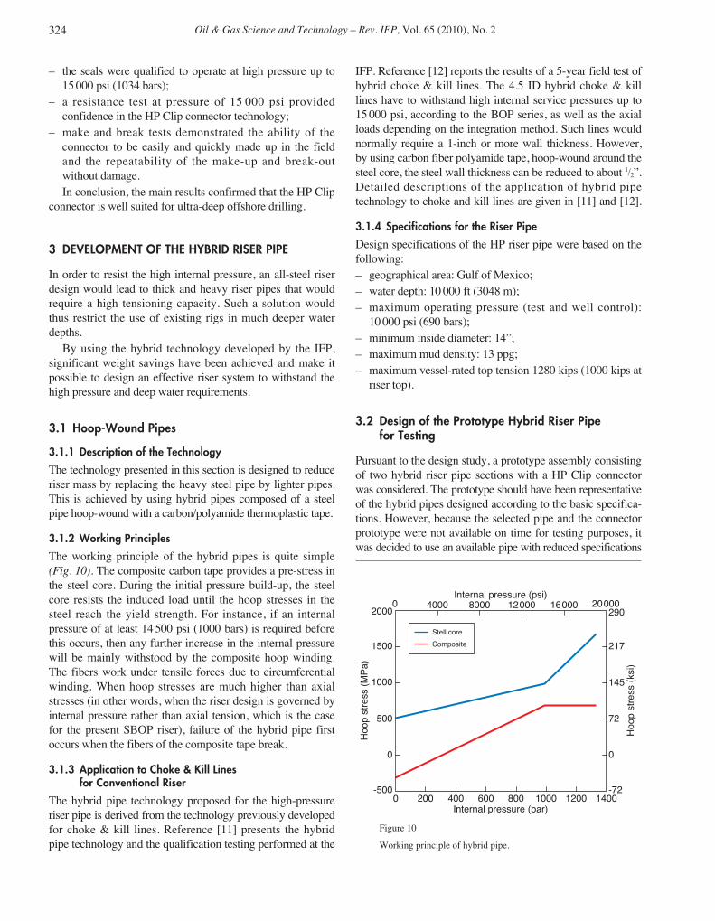
3.1.2 Working Principles
The working principle of the hybrid pipes is quite simple(Fig. 10). The composite carbon tape provides a pre-stress inthe steel core. During the initial pressure build-up, the steelcore resists the induced load until the hoop stresses in thesteel reach the yield strength. For instance, if an internalpressure of at least 14 500 psi (1000 bars) is required beforethis occurs, then any further increase in the internal pressurewill be mainly withstood by the composite hoop winding.The fibers work under tensile forces due to circumferentialwinding. When hoop stresses are much higher than axialstresses (in other words, when the riser design is governed byinternal pressure rather than axial tension, which is the casefor the present SBOP riser), failure of the hybrid pipe firstoccurs when the fibers of the composite tape break.
3.1.3 Application to Choke & Kill Lines for Conventional Riser
The hybrid pipe technology proposed for the high-pressureriser pipe is derived from the technology previously developedfor choke & kill lines. Reference [11] presents the hybridpipe technology and the qualification testing performed at the
IFP. Reference [12] reports the results of a 5-year field test ofhybrid choke & kill lines. The 4.5 ID hybrid choke & killlines have to withstand high internal service pressures up to15 000 psi, according to the BOP series, as well as the axialloads depending on the integration method. Such lines wouldnormally require a 1-inch or more wall thickness. However,by using carbon fiber polyamide tape, hoop-wound around thesteel core, the steel wall thickness can be reduced to about 1/2”.Detailed descriptions of the application of hybrid pipetechnology to choke and kill lines are given in [11] and [12].
3.1.4 Specifications for the Riser Pipe
Design specifications of the HP riser pipe were based on thefollowing:– geographical area: Gulf of Mexico;– water depth: 10 000 ft (3048 m);– maximum operating pressure (test and well control):
10 000 psi (690 bars);– minimum inside diameter: 14”;– maximum mud density: 13 ppg;– maximum vessel-rated top tension 1280 kips (1000 kips at
riser top).
3.2 Design of the Prototype Hybrid Riser Pipefor Testing
Pursuant to the design study, a prototype assembly consistingof two hybrid riser pipe sections with a HP Clip connectorwas considered. The prototype should have been representativeof the hybrid pipes designed according to the basic specifica-tions. However, because the selected pipe and the connectorprototype were not available on time for testing purposes, itwas decided to use an available pipe with reduced specifications
324
200 1400400 600 800 1000 1200
16 000 20 0000Internal pressure (psi)
12 00080004000
0
Hoo
p st
ress
(M
Pa)
Hoo
p st
ress
(ks
i)
2000
-500
1500
1000
500
0
217
290
145
72
0
-72
Internal pressure (bar)
Stell core
Composite
Figure 10
Working principle of hybrid pipe.
ogst08065_Persent 26/03/10 16:04 Page 324

and a dummy connector made of similar material to the HPClip connector.
The design study of the hybrid riser pipe was thus revised onthe basis of the available pipe and materials in order to applysimilar stresses in both the steel and the composite sections.
3.2.1 Pipe Specification
– outside diameter: 16” (406.4 mm);– steel wall thickness: 0.57” (14.6 mm).
3.2.2 Materials
– the steel grade of the pipe was API 5CT N80 Q-HC;– the steel grade of the dummy connector was ASTM A182
F22 with the same characteristics as the material of the HPClip connector (AFNOR 20CNDV10).The composite material, in the form of composite tape,
was made of carbon fibers (50% volume) embedded inthermoplastic resin (polyamide 12). The composite tape hadthe following mechanical properties:– young modulus: El = 15 Mpsi (105 000 MPa) in the fiber
direction;– tensile strength: Su = 246 ksi (1700 MPa).
3.2.3 Design Criteria
Steel
According to the API RP 16Q and API RP 2RD, the followingcriterion must be satisfied in the steel core of the hybrid pipe:
σVM ≤ 0.667 × Cf × Sy
The same criterion was retained for the steel part of thetransition region in the hybrid pipe.
Composite materialBased on the manufacturing company’s (Composites Aquitaine)experience with composite material design, we assumed thatthe circumferential stresses would not exceed 40% of theultimate strength of the carbon fibers (to be modulated by thecoefficient Cf as shown in Tab. 1):
σCC ≤ 0.4 × Cf × Su
TABLE 2
Operating conditions Steel Composite
Drilling σVM ≤ 66.7% × Sy σCC ≤ 40% × Su
Well control σVM ≤ 80% × Sy σCC ≤ 48% × Su
Pressure testing σVM ≤ 90% × Sy σCC ≤ 54% × Su
3.2.4 Design Loads
Seven operating cases were taken into account for the designof the riser (Tab. 1).
A computer program has been developed by the IFP todesign the main part of hybrid riser pipes under differentconditions of pressure (internal, external), axial loads andtemperature. The results are given in Table 3 in percentage ofyield for the steel core and in percentage of the ultimatestrength for the composite tape in the last line. In order to verifythat the pipe will meet the criteria for stresses in the transitionsection, a stress amplification factor of 1.07 was applied.
E Persent et al. / Development of a 14-inch ID High-Pressure Hybrid Riser for SBOP Drilling 325
TABLE 3
Operating envelope of the hybrid riser pipe for testing
Diff. pressure 0 psi 1450 2900 4350 5800 7250 8700 10 150 psi 11 600 psi
Eff. tension 0 bar 100 200 300 400 500 600 700 800
0 kips 0 ton 41% 32% 27% 28% 34% 43% 54% 66% 78%
220 100 45% 38% 34% 35% 40% 49% 59% 70% 82%
440 200 50% 44% 41% 42% 47% 55% 64% 75% 86%
660 300 55% 50% 48% 50% 54% 61% 70% 80% 91%
880 400 61% 57% 55% 57% 61% 68% 76% 86% 96%
1100 500 67% 64% 63% 64% 69% 75% 83% 92% 102%
1325 600 74% 71% 70% 72% 76% 82% 89% 98% 107%
in composite 26% 29% 32% 35% 37% 40% 43% 46% 49%
Code of colors
Type of operation allowed Drilling Control Testing None
Steel main part (% of yield) 0-62% 62-75% 75-84% > 84%
Steel transition part (% of yield) 0-67% 67-80% 80-90% > 90%
Composite (% of strength) 0-40% 40-48% 48-54% > 54%
ogst08065_Persent 26/03/10 16:04 Page 325

Oil & Gas Science and Technology – Rev. IFP, Vol. 65 (2010), No. 2
As a result of the analyses, the design load for the designof the transition section was set to:– maximum operating pressure: 10 000 psi (690 bar);– tensile load: 440 kips (200 tons).
3.2.5 Manufacturing Process
The manufacturing process consists of winding multiple layersof composite tape around the steel pipe. The pipe rotatesaround its axis and a winding arm moving parallel to the pipecarefully applies a well-controlled tension to the compositetape. The tape is locally melted using a small blowtorch andthe adjacent layers are fused together to create a solid layeraround the steel core (Fig. 11).
3.2.6 Transition Section
As usual for drilling risers, the connector pieces (male andfemale members) are welded onto the ends of the steel pipe.In the case of a hybrid pipe, the design of the transitionsection (tapered section) from the hybrid pipe to the endconnectors requires special attention as it also contains thetermination of the composite hoop wraps. The pipe-to-connector welds are made first. Then the welds are ground(planed down) to constitute a cylindrical assembly. Thecomposite layers are then laid down covering the weld untilthey reach the tapered ends of the connector. Some additionallayers may be required to allow a good transition of stressesand deformations between the pipe and the connector.
The design of the transition section is of prime importanceas it may be the leak point of the riser joint. Its design wasdetermined by using the finite element method.
3.2.7 Finite Element Analyses
The finite element analyses were performed with the SystusV.2004 program from ESI Group.
Due to the near 90° winding angle of composite layersaround the steel pipe, an axisymmetric finite element modelis sufficient to precisely capture the real test model.Therefore, two-dimensional models, including the pipe, thedummy connector and all the layers of the composite hoop,were used to validate and optimize the design of thetransition of the pipe to the Clip connector.
The transition section was modeled with parabolicaxisymmetric elements (triangle or quadrilateral with 6 or8 nodes) whose size was about 5 mm everywhere.
The lower end of the pipe was fixed in the longitudinaldirection. The materials were supposed to be elastic. Anorthotropic behavior law was considered for the compositematerial.
The transition section was designed for the followingloading cases:– manufacturing process;– maximum operating pressure: 10 000 psi (690 bar);– tensile load: 440 kips (200 tons).
These models allowed precise simulations of the compositehoop-winding process as well as the behavior of the riserpipe under the combined effects of pressure and tension.Regarding the composite design, several winding processeswere studied by varying the number of layers and tension inthe layers.
Finite element analyses demonstrated that the design studyof the transition area may be divided into two separate problems.The axial stress governs the design of the transition geometryin steel, whereas the composite winding process leads to thedefinition of the composite overlayers. For the hybrid riserconsidered in this study, optimization of the transition sectionthrough FEA showed that no additional layer was needed inthe transition section (Fig. 12).
326
Figure 11
Hybrid pipe during manufacturing process.
Figure 12
Design of the transition section from hybrid pipe to the endconnectors.
ogst08065_Persent 26/03/10 16:04 Page 326

3.2.8 Final Design and Properties of the Tested HybridRiser Pipe
The main dimensions of the hybrid pipe were:
Steel pipe:– outside diameter: 16” (406.4 mm);– steel wall thickness: 0.57” (14.6 mm).
Composite hoop wrap (pipe body + transition section):– number of composite layers: 36;– composite thickness: 0.43” (10.8 mm);– pre-stress in steel core: 39 ksi (270 MPa).
3.3 Hybrid Riser Pipe Testing
3.3.1 Testing Principles
A testing program was carried out at the IFP to qualify theapplication of the hybrid pipe technology to high-pressuredrilling risers.
Static and dynamic (fatigue) tensile tests were performed atthe IFP on the same device as the one used for the connector.
Burst tests of hybrid pipes were performed without theend-pressure effect, using a large mandrel placed inside thehybrid tube. Steel collars were previously placed at the end ofthe tube to prevent burst at these locations.
Outer composite temperature was obtained by flowing aregulated hot water in a steel cylinder encircling the hybridpipes.
Collapse tests were performed at the IFREMER (Brest,France) using a hyperbaric testing tank of 2 m in height and 1 min diameter, with a maximum pressure of 14504 psi (1000 bar).
3.3.2 Reference Tests (Burst and Collapse)
Two 6.5-ft (2-m) long sections of hybrid riser pipe weremanufactured by Composites Aquitaine near Bordeaux,France, according to the definition derived from the designstudy.
Burst Test (Fig. 13)A pressure test of the first hybrid pipe section up to the burst(characterized by the break of the fibers) was performedwithout the end-pressure effect. The burst pressure was22 335 psi (1540 bars), slightly over the predicted value of20 305 psi (1400 bars).
Collapse Test (Fig. 14)An external pressure test of the other hybrid pipe section upto the collapse was performed at the IFREMER. The collapsepressure was 6527 psi (450 bars), slightly over the predictedvalue of 6090 psi (420 bars).
3.3.3 Prototype Riser Pipe Assembly
A prototype assembly, consisting of two sections of hybridriser pipe separated by a dummy connector, was manufac-tured and tested (Fig. 15). The French Welding Institute (IS)
E Persent et al. / Development of a 14-inch ID High-Pressure Hybrid Riser for SBOP Drilling 327
Figure 14
Collapse test of a hybrid pipe
Pcollapse = 6527 psi (450 bars).
Figure 13
Burst test of a hybrid pipe
Pburst = 22 335 psi (1540 bars).
ogst08065_Persent 26/03/10 16:04 Page 327

Oil & Gas Science and Technology – Rev. IFP, Vol. 65 (2010), No. 2
developed a procedure for welding the pipe onto the connec-tor. Butt-joint welded samples were prepared, machined andtested. The welded samples endured at least 4.5 millioncycles at a fatigue loading of 46.7 ± 9 ksi (322 ± 62 MPa).Testing results were in accordance with standard S-N curvessuch as API X’.
Welds of the prototype assembly were made according tothe welding procedure established by the IS and werecontrolled by means of γ-ray examination. No out-of-tolerance defects were detected in the welds before startingthe tests.
3.3.4 Static Testing
The prototype assembly was instrumented with biaxial straingages in the main part of the pipe sections and in thetransition sections (28 gages), in order to verify the designcalculation. The strain gages were bonded onto the compositeoverwrap.
Verification tests consisted of various combinations ofinternal pressure (up to 10000 psi) and tension (up to 660 kips).The following static tests were performed:– a pressure test at the maximum operating pressure: 10000 psi
(690 bars);– a tensile test at 660 kips (300 tons);– a combined pressure and tension test up to 5800 psi and
660 kips.Comparison between the static strain measurements and
the finite element calculations showed that:– the hoop strain measurements were in good agreement
with FEA simulations. For the significant strains, thedifference between tests and simulations was alwayslower than 15% (Fig. 16). That difference could beexplained by the initial state of the hybrid tube, which isnot perfect. Especially, discrepancy between strain gagemeasurements (Fig. 16) is not surprising;
– a large dispersion of measured axial strains was observed.Significant differences between test results and FEAsimulations were observed.As the composite hoop wraps were not designed to
withstand axial load, it was difficult to get realistic axialstrain measurements from the strain gages on compositeoverwraps. Hence, poor agreement in predicted andmeasured axial strains was not a surprise.
3.3.5 Fatigue Testing
The prototype assembly was tested in the following fatigueconditions (Fig. 17):– internal pressure of 6672 psi (460 bar);– dynamic tensile load of 287 ± 165 kips (130 t ± 75 t);– outer composite temperature: 70 °C;– 5 × 10⁶ cycles were planned.
Although five million cycles were planned, the fatiguetesting was interrupted after 450 000 cycles due to failure in aweld of the assembly.
3.3.6 Welding Problem and Discussion
A close examination of welded joints extracted from the failedpipe, including macroscopic and microscopic examinationssuch as metallographic and fractographic evaluation, wascarried out by the Welding Institute (IS). Examination of thewelded joint fracture revealed a 26-mm-long through-wallcrack and a very oxidized surface, 19 mm long and 5 mmdeep, suggesting that initial damage had existed before the
328
Figure 15
Hybrid riser prototype assembly.
40003500300025002000150010005000
Str
ain
(μst
)
1000
0
800
600
400
200
Pressure (psi)
Gage 2
Gage 4
Gage 6
Gage 8
FEA
Figure 16
Axial strain measurements vs FEA simulations. Pressure testup to 3600 psi (250 bars).
ogst08065_Persent 26/03/10 16:04 Page 328

tests. The IS concluded that the failure of the welded jointhad resulted from a defect that appeared during the weldingprocess, that could be attributed to a cold cracking effect. TheIS believed that the specified preheat temperatures were notcorrectly respected during the welding process.
The tests confirmed the ineffectiveness of radiographicexamination in detecting cracks in the weld. No out-of-tolerance defects were detected in the welds before startingthe tests. The IS’s recommendation was to use a combinationof radiographic and ultrasonic examinations. The combineduse of both techniques would allow detection of this type ofdefect in the weld. Finally, particular care must be followedin the welding process, strictly respecting the procedure, suchas preheat temperatures.
3.3.7 Final Tests (Burst and Collapse)
Both sections of the hybrid riser pipe were extracted from theprototype assembly after partial fatigue testing. Two pressuretests (collapse and burst) were performed and compared withthe reference test results in order to determine if there was aloss of performance due to fatigue.
Burst Testthe test sample included a pipe to connector transition. Theburst test was carried out in the same manner as the refer-ence test. The test was terminated at 21100 psi (1455 bars)due to a premature leakage in the test fixture. However,breakage of some carbon fibers in the hoop wrap wasobserved, indicating that the hybrid pipe was close to burst.The burst pressure was comparable with the 22 335 psi(1540 bars) burst pressure obtained in the reference test.
Collapse TestThe collapse test was performed at the IFREMER in the sameconditions as the reference test. The collapse pressure was
6670 psi (460 bars) compared with the 6527 psi (450 bars)obtained in the reference test.
3.4 Conclusion for the Developmentof the Hybrid Riser Pipe
After design studies were carried out through CAD andextensive FEA, a testing program including static, burst andcollapse tests as well as cyclic fatigue testing was conductedto qualify a 14-inch ID high-pressure hybrid riser pipe. Themain results are listed below:– comparison between static strain measurements and finite
element calculations shows that the hoop strain measure-ments were in quite good agreement with simulations. Forthe significant strains, the difference between test and sim-ulation was lower than 15%;
– the burst of a section of 16-inch OD hybrid pipe occurredat a pressure greater than 21100 psi (1455 bars) afterfatigue testing compared with the 22 335 psi (1540 bars)obtained before the fatigue;
– the collapse test performed after fatigue testing showed nodegradation in the hybrid pipe performance. The collapseoccurred above 6500 psi (450 bars);
– a procedure for welding the N80 Q-HC steel pipe onto theF22 dummy connector was developed. Fatigue tests per-formed on butt-joint welded samples were in accordancewith standard S-N curves such as the API X’ curve;
– the fatigue test performed on a hybrid riser prototypeassembly was interrupted after 450 000 cycles due to afailure in a weld of the assembly.Pursuant to this study, a new hybrid riser pipe prototype
should be properly manufactured and tested in fatigueconditions in order to complete the qualification of hybridpipe technology for ultra-deep sea drilling with a surfaceBOP. Further work to characterize the performance of thetransition section is also needed. However, due to lack ofbudget, such work has not been done to date.
CONCLUSION
The development work of the High-Pressure Clip Riser for a10 000 ft water depth and 10 000 psi pressure for SurfaceBOP (SBOP) drilling operations was performed throughfinite element analysis and validated by static and dynamic(fatigue) laboratory testing, paving the way for fieldapplications. The achieved high burst and collapsed pressuresfor a relatively lightweight riser are particularly promising fordeepwater and high-pressure drilling and development fromfloaters.
Detailed conclusions for the development of the HP Clipconnector and the Hybrid Riser pipe are listed in thecorresponding sections of the paper.
E Persent et al. / Development of a 14-inch ID High-Pressure Hybrid Riser for SBOP Drilling 329
Figure 17
Prototype assembly on the fatigue bench.
ogst08065_Persent 26/03/10 16:04 Page 329

Oil & Gas Science and Technology – Rev. IFP, Vol. 65 (2010), No. 2
The analytical tools have been successfully calibrated andcan be used to design high-pressure risers for differentapplications. The encountered welding issues should not beseen as a major concern, as they can be controlled andmanaged within known engineering practice at themanufacturing stage of future commercial products.
The riser designed and tested during the course of thisstudy shows that for Surface BOP drilling with a floater,using a lightweight high-pressure riser, in combination withother complementing technologies, will enable a drillingvessel to drill at three times its nominal maximum waterdepth. Effort is underway to develop a field trial program todemonstrate the benefits of the lightweight high-pressuredrilling riser.
ACKNOWLEDGEMENTS
The authors wish to express their thanks to Shell InternationalExploration & Production, Aker Kværner Subsea andComposites Aquitaine for supporting the project. They aregrateful to their colleagues for reviewing the paper.
REFERENCES
1 Brander G., Magne E., Newman T., Taklo T., Mitchell C. (2004)Drilling in Brazil in 2887 m Water Depth using a Surface BOPsystem and a DP Vessel, SPE paper 87113-MS.
2 Guidelines for the use of Surface BOP’s from floating MODU’s,IADC, 2004.
3 Azancot P., Magne E., Zhang J. (2002) Surface BOP –Management System & Design Guidelines, SPE paper 74531-MS.
4 API RP 16Q (1993) Recommended Practice for Design,Selection, Operation and Maintenance of Marine DrillingSystems, First Edition, Formerly RP2Q and RP2K.
5 API Spec 16R (1997) Specification for Marine Drilling RiserCouplings, First Edition, Formerly API RP 2R.
6 API Spec 2RD (1998) Design of risers for Floating ProductionSystems (FPSS) and Tension-Leg Platform (TLPS), First Edition.
7 Heurtier J.M., Biolley F., Berhault C. (1998) Fully coupleddynamic analysis of rigid lines, Proceedings of ISOPE 98,Montreal, pp. 246-252.
8 Toumit S. (2009) Diodore and DeepLines software validationreport, PRINCIPIA réf. DVA.945.054.01, février 2009.
9 Lepeuvedic J.P., Guesnon J., Soleille L.M. (1984) A fastcoupling for a deepwater drilling riser, SPE Paper 13153, 59thAnnual Technical Conference and Exhibition of the SPE,Houston, 1984.
10 De Bonnafos O., Guesnon J. (2000) Riser system for 3000 mwater depth – Pride Africa/Pride Angola approach, IADC WorldDrilling Congress, Paris, 2000.
11 Guesnon J., Gaillard C., Schaeffner P. (2002) Hybrid Tubes forChoke and Kill Lines, Offshore Technology Conference,Houston, 2002.
12 Poirette Y., Guesnon J., Averbuch D., Dupuis D. (2009) FieldTesting of Hybrid Choke & Kill Lines, Offshore TechnologyConference, Houston, 2009.
Final manuscript received in June 2009Published online in November 2009
330
Copyright © 2009 Institut français du pétrolePermission to make digital or hard copies of part or all of this work for personal or classroom use is granted without fee provided that copies are not madeor distributed for profit or commercial advantage and that copies bear this notice and the full citation on the first page. Copyrights for components of thiswork owned by others than IFP must be honored. Abstracting with credit is permitted. To copy otherwise, to republish, to post on servers, or to redistributeto lists, requires prior specific permission and/or a fee: Request permission from Documentation, Institut français du pétrole, fax. +33 1 47 52 70 78, or [email protected].
ogst08065_Persent 26/03/10 16:04 Page 330