monitoring of free standing hybrid riser –west africa - subsea europe paris...project overview...
TRANSCRIPT
Monitoring of Free Standing g gHybrid Riser – West AfricaSubsea Europe –Nov 2011p

ContentsContents
Project OverviewProject OverviewField layout & riser configuration
Monitoring EquipmentCustomer objectivesCustomer objectivesInstallation procedures
Data results and conclusionsWhere can this system be used again?Where can this system be used again?

Project OverviewProject Overview
Operator utilised 9 Free Standing Hybrid Risers (FSHR’s) p g y ( )for field layoutInstalled in the West Coast of AfricaInstalled in the West Coast of AfricaTension Monitoring System (TMS) used on the lower riser assembly (LRA) of each of the FSHR’s during installationassembly (LRA) of each of the FSHR s during installationRiser installed using J‐Lay installation vessel

Fi ld L O iField Layout OverviewWater depths 1800m to 2100mCentrally located FPSO – turret mounted

Riser Functional RequirementsRiser Functional Requirements
20 year in service design lifey gOperate in water depth of 2100mHandle a range of fluid densities temperatures &Handle a range of fluid densities, temperatures & slugging loadsM d l d i bl f t d di ti (thi fi ld &Modular design capable of standardisation (this field & future projects)Accommodate standby scenario prior to flexible connection to FPSODiverless flexible jumper installation and retrievalAll risers to be piggable for construction and testing.All risers to be piggable for construction and testing.
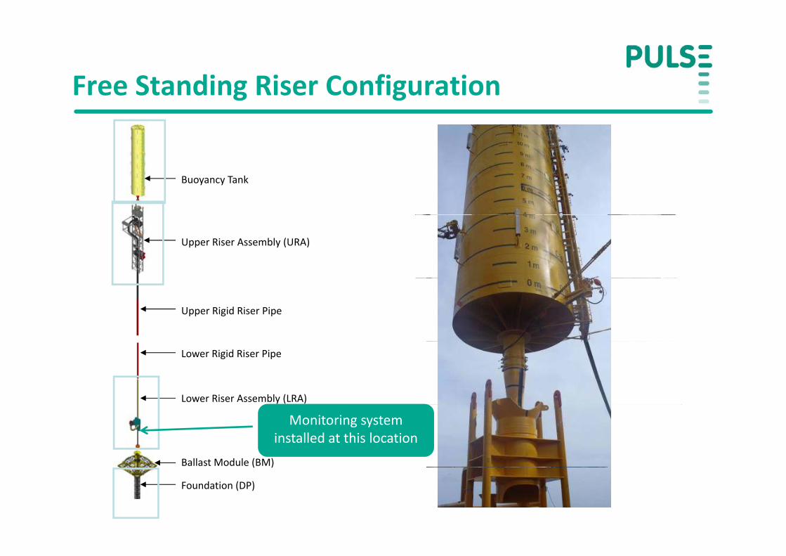
Free Standing Riser ConfigurationFree Standing Riser Configuration
Buoyancy Tank
Upper Riser Assembly (URA)
Upper Rigid Riser Pipe
Lower Rigid Riser Pipe
Lower Riser Assembly (LRA)
Ballast Module (BM)
Monitoring system installed at this location
( )
Foundation (DP)

Monitoring Equipment General AssemblyGeneral Assembly
Subsea LoggerLogs data from the strain
Logger HolderHolds logger canister which Logs data from the strain
gauge and displays using visual display
ggcan be retrieved/deployed by ROV
ROV ConnectorLogger can be connected to gauges using ROV
S i G P kStrain Gauge Package4 gauges installed at 90 deg configuration N‐E‐S‐WSubsea Cable
Transmits power and signal between gauges and logger
Objectives for Monitoring SystemObjectives for Monitoring System
Check base tension and indirectly buoyancy tank upthrusty y y pManage risk during the ballasting and deballasting procedureVerify integrity of integrity of buoyancy tanky g y g y y yComparison versus calculated upthrust of each compartment in buoyancy tank
Priority given to proven technology, simplicity, reliability and fast‐track delivery.and fast track delivery.
Monitoring EquipmentInstallation ProceduresInstallation Procedures
Strain GaugegInstalled at the contractors yard prior to shipping to West AfricaSurface preparation requiredp p qHanger in semi‐controlled environment
Logger Canister HolderLogger Canister HolderInstalled in the contractors yardBolted to LRABolted to LRA
Logger Canisteri i l d l d k b iInitial deployment on deck by engineer
Deployed and retrieved by ROV for subsequent measurements of other LRA’sof other LRA’s
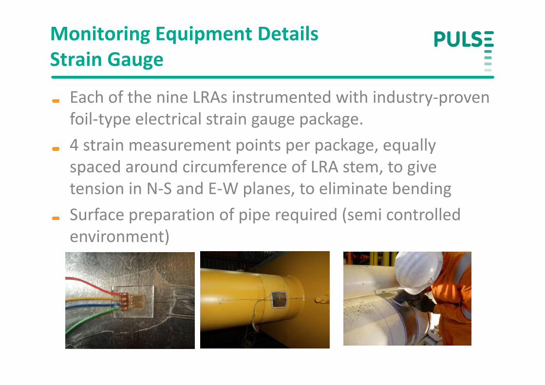
Monitoring Equipment DetailsStrain GaugeStrain Gauge
Each of the nine LRAs instrumented with industry‐proven y pfoil‐type electrical strain gauge package.4 strain measurement points per package, equally4 strain measurement points per package, equally spaced around circumference of LRA stem, to give tension in N‐S and E‐W planes, to eliminate bendingtension in N S and E W planes, to eliminate bendingSurface preparation of pipe required (semi controlled environment)environment)
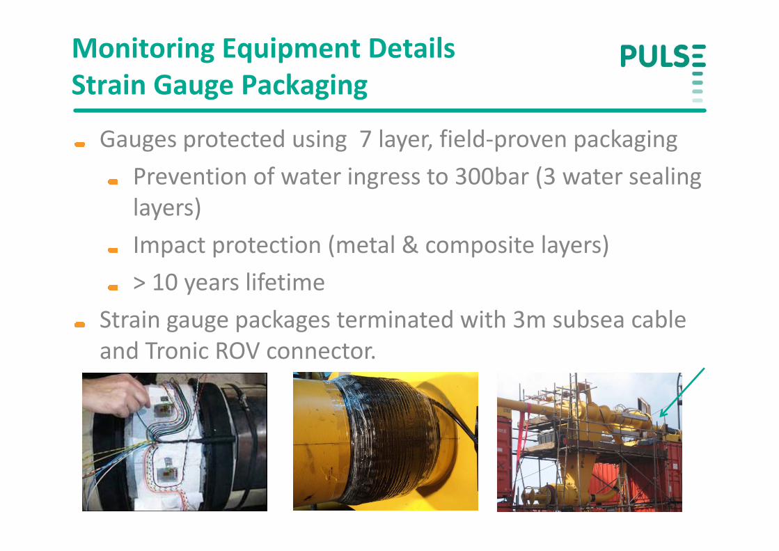
Monitoring Equipment DetailsStrain Gauge PackagingStrain Gauge Packaging
Gauges protected using 7 layer, field‐proven packaging g p g y , p p g gPrevention of water ingress to 300bar (3 water sealing layers)layers)Impact protection (metal & composite layers)10 lif ti> 10 years lifetime
Strain gauge packages terminated with 3m subsea cable and Tronic ROV connector.
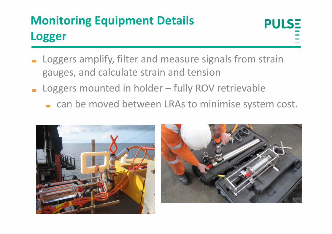
Monitoring Equipment DetailsLoggerLogger
Loggers amplify, filter and measure signals from strain gg p y, ggauges, and calculate strain and tensionLoggers mounted in holder – fully ROV retrievableLoggers mounted in holder fully ROV retrievable
can be moved between LRAs to minimise system cost.

Monitoring Equipment DetailsLogger CannisterLogger Cannister
Loggers rated >300 bar. ggMore than 500 deployments &13 years experienceMTBF of 47 yearsMTBF of 47 years
Data is displayed in real‐time using visual displayDisplay is light‐activated ‐ saving battery power

Data MeasurementsData Measurements
Data recorded at discrete events As LRA lowered to depth
Verification of pressure effectJust before stab‐in
A “zero” reading – compensate for pressure and temperature effects
Multiple times during buoyancy can deballastingVerification of buoyancy can integrity
ll “b bbl ”post installation ‐ “bubble survey”

Overview of Data ObtainedOverview of Data Obtained
Example of data obtained from Pulse system for p yinstallation of water injection riser :
ry units)
on (arbitra
Riser Ten
sioR
Conclusions from measurementsConclusions from measurements
Real‐time tension feedback allowed upthrust given by p g yeach compartment in buoyancy can to be measured and compared against theoretical resultsp gIntegrity of buoyancy canister verified
Results of Pulse system within 3% of calculated valuesResults of Pulse system within 3% of calculated values (within specified accuracy)
B di i i d t t d (i i ti i t iBending in riser detected (i.e. variation in strain gauges at 90 degree orientations)
Bonded strain sensors as permanent installation?installation?
Possibility to upgrade this system for permanent y pg y pmonitoring for medium to long‐term
Deploy permanent loggers in holdersp y p ggUse acoustic modems to communicate data to surface
Limitations includePosition of monitoring system at base of riser Fluid flow canPosition of monitoring system at base of riser. Fluid flow can affect tension measurements –interpretation required to accurately provide information on buoyancy can upthrusty p y y pLifetime of system. In principle > 10 years. Reality – less certain as installed in semi‐controlled conditions. Not lab conditions
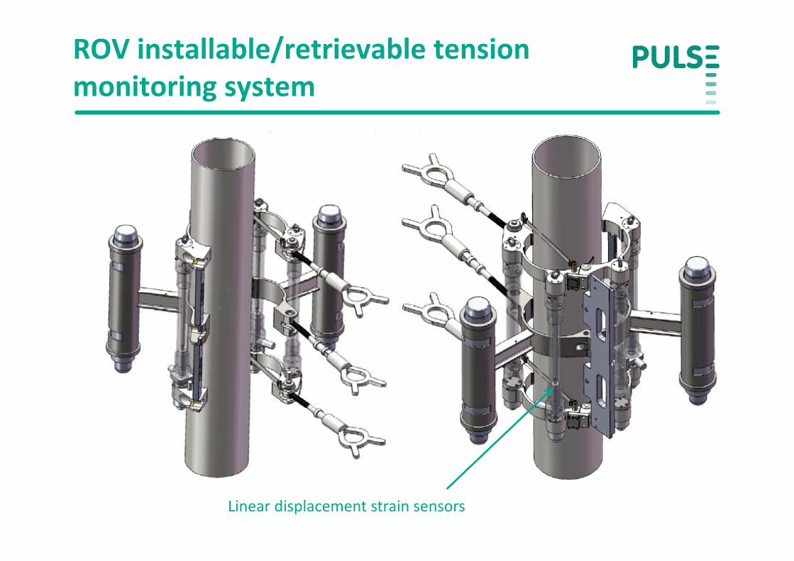
ROV installable/retrievable tension monitoring systemmonitoring system
Insert picture of ROV deployable INTEGRIcollarp p y
Linear displacement strain sensors
Future Applications for bonded strain gauge technologygauge technology
Suitable for medium term applications where ppinformation critical to installation/operationsExamples includeExamples include
Tension monitoring system for drilling risers (also bending moment, fatigue, torsion), g , )Mooring line monitoring (Inter‐M‐Pulse link)Hoop stress/ non‐intrusive pressure monitoringHoop stress/ non intrusive pressure monitoringInstallation monitoring
Tendons & tethers (Tension Leg Platforms, BSR – buoy monitoring)( g , y g)Stinger

ConclusionsConclusions
Successful installation with minimal disruption to poperationsProvided accurate information to within specificationsProvided accurate information to within specificationsGave operator and installation contractor confidence that latching and ballasting/de ballasting operations ranlatching and ballasting/de‐ballasting operations ran successfullyC t ff tiCost effective
20% cost of alternative monitoring systems
Potential to upgrade to permanent installation
Thank YouThank Youwww.pulse‐monitoring.com