development and management plan - … · interstate reliability project development and management...
TRANSCRIPT

INTERSTATE RELIABILITY PROJECT
DEVELOPMENT AND MANAGEMENT PLAN
for
NEW 345-kV TRANSMISSION LINES AND RELATED MINOR MODIFICATIONS TO ADJACENT LINES
VOLUME 1
DRAFT FOR PUBLIC REVIEW
May 2013
Prepared by:
The Connecticut Light and Power Company

This page intentionally left blank.
Interstate Reliability Project New 345-kV Transmission Lines and Development & Management Plan Related Minor Modifications to Adjacent Lines
The Connecticut Light and Power Company i May 2013 DRAFT
VOLUME 1
TABLE OF CONTENTS 1. INTRODUCTION ............................................................................................................................. 1
1.1 Project Overview and Purpose of the Plan .............................................................................. 1
1.2 Organization of the D&M Plan ................................................................................................ 3
2. REGULATORY APPROVALS AND CONSULTATIONS .......................................................... 19
2.1 Regulatory Approvals and Requirements .............................................................................. 19
2.2 Consultations ......................................................................................................................... 19
3. GENERAL CONSTRUCTION PROCEDURES ............................................................................ 23
3.1 Construction Management and Contact Information ............................................................. 24
3.2 General Construction Sequence: Overview ........................................................................... 24
3.3 Construction Field Offices, Contractor Yards, and Staging Areas ........................................ 25
3.4 Vegetation Removal .............................................................................................................. 25
3.5 Access Roads and Work Pads ................................................................................................ 26
3.5.1 Access Roads .............................................................................................................. 26
3.5.2 Work Pads .................................................................................................................. 29
3.6 Structure Installation .............................................................................................................. 30
3.6.1 Foundation Types and Excavation ............................................................................. 30
3.6.2 Structure Placement .................................................................................................... 30
3.6.3 Structure Grounding ................................................................................................... 31
3.7 Conductor Stringing ............................................................................................................... 31
3.8 ROW Cleanup and Restoration ............................................................................................. 31 3.9 Modifications to Adjacent Lines............................................................................................ 33
3.9.1 Guy Wire and Anchore Relocations: Existing 345-kV and 115-kV Lines ................ 30
3.9.2 Ground Wire Additions: Existing 345-kV Line Structures ....................................... 34
3.9.3 New Transmission Line Structure: 69-kV Line ........................................................ 35 3.9.4 Distribution Line Pole Relocations ............................................................................ 35
4. CONSTRUCTION SCHEDULE, OUTAGES, AND WORK HOURS.......................................... 37
4.1 Construction Schedule, Including Outages ............................................................................ 37
4.2 Work Hours ........................................................................................................................... 38
5. SPECIAL CONSTRUCTION PROTOCOLS AND PROCEDURES ............................................ 39
5.1 Erosion and Sedimentation Control Plan ............................................................................... 39
Interstate Reliability Project New 345-kV Transmission Lines and Development & Management Plan Related Minor Modifications to Adjacent Lines
The Connecticut Light and Power Company ii May 2013 DRAFT
5.2 Water Resources .................................................................................................................... 40
5.2.1 Surface Water Resource Crossing Summary ............................................................. 40
5.2.2 Water Resource Crossing Techniques ........................................................................ 41 5.2.2.1 Watercourse Crossing Methods ..................................................................... 41 5.2.2.2 Wetland Crossing Methods ........................................................................... 41 5.2.3 Flood Zones and Stream Channel Encroachment Lines ............................................. 45
5.2.4 Aquifer Protection ...................................................................................................... 46
5.2.5 Drainage ..................................................................................................................... 46
5.3 Vernal Pools and Amphibian Breeding Habitat .................................................................... 47
5.4 Protection Measures For State-Listed Species ....................................................................... 49 5.4.1 Overview .................................................................................................................... 40
5.4.2 Eastern Ribbon Snake ................................................................................................ 50
5.4.3 Eastern Hognose Snake ............................................................................................ 451
5.4.4 Aquatic Snail .............................................................................................................. 51
5.4.5 Moustached Clubtain Dragonfly ................................................................................ 52
5.4.6 Brook Floater .............................................................................................................. 52
5.4.7 Moths and Butterflys (Lepidoptera) ........................................................................... 53
5.5 Air Quality Protection (Minimization of Dust and Vehicle Idling Protocol) ........................ 55
5.6 Procedures For Crossing Public Trails, Preserved Open Space, and Recreational Areas ..... 56 5.6.1 Consultations and Site-Specific Plans ........................................................................ 58
5.6.2 Mansfield Hollow Area .............................................................................................. 58
5.7 Handling and Disposition of Excavated Soil, Groundwater, Recyclable Materials, and Wastes ............................................................................................................................. 63
5.8 Lighting and Noise Mitigation ............................................................................................... 63
5.9 Site Access, Traffic Control, and Construction Signs ........................................................... 64
5.10 Cultural Resources ................................................................................................................. 64
5.10.1 Protection Measures ................................................................................................... 64
5.10.2 Unanticipated Cultural Resources Discovery Procedures .......................................... 65
5.11 Construction Equipment / Vehicle Washing and Cleaning ................................................... 65
5.12 Water Sources ........................................................................................................................ 66
5.13 Utility Crossings .................................................................................................................... 66
5.14 Methods to Prevent or Discourage Unauthorized Use of the ROWs, Including ATVs ......... 66
5.15 FAA Notice of Presumed Hazard Structures ......................................................................... 67
5.16 Winter Work, ROW Stabilization, and ROW Monitoring Protocol ...................................... 68
5.17 Post-Construction EMF Monitoring Plan .............................................................................. 68
5.18 Hawthorne Lane ROW Shift.................................................................................................. 69
5.19 Blasting Procedures ............................................................................................................... 69

Interstate Reliability Project New 345-kV Transmission Lines and Development & Management Plan Related Minor Modifications to Adjacent Lines
The Connecticut Light and Power Company iii May 2013 DRAFT
5.20 Mount Hope Montessori School Landscaping ....................................................................... 70
6. ENVIRONMENTAL INSPECTION .............................................................................................. 71
6.1 Independent Environmental Consultant ................................................................................. 71
6.2 CL&P’s Environmental Compliance Program ...................................................................... 71
7. NOTICES AND REPORTS ............................................................................................................ 73
7.1 Notices to the Council: Start and Completion of Construction (Including Access and Vegetation Clearing) .............................................................................................................. 73
7.2 Notice of Changes to D&M Plan ........................................................................................... 73
7.2.1 D&M Plan Changes Requiring Notice to the Council ............................................... 73
7.2.2 D&M Plan Change Approval Process ........................................................................ 74
7.2.3 D&M Plan Change Documentation and Reporting .................................................... 75
7.3 Reports ................................................................................................................................... 75
8. PUBLIC REVIEW AND OUTREACH .......................................................................................... 79
8.1 Public Review and Input to the D&M Plan ........................................................................... 79
8.2 Public Outreach during Construction .................................................................................... 80
9. GLOSSARY OF TERMS ................................................................................................................ 81
APPENDICES Appendix A: Vegetation Clearing Plan
Attachment 1: Northeast Utilities’ Vegetation Clearing Specifications: Right-of-way Vegetation Initial Clearing for 115- and 345-kV Transmission Lines (OTRM 030.001) Attachment 2: Vegetation Clearing Procedures and Practices for Transmission Line Sections (OTRM 230) Attachment 3: CL&P’s brochure regarding procedures for landowners to request timber cleared from the ROW on their property (“Making Requests for Wood” www.NUrightsofway.com)
Appendix B: Wetlands and Waterbodies Avoidance and Minimization Protocols
Appendix C: Summary Report on Farmland Protection Measures and Consultations with
Farmland Property Owners and Lessees
Appendix D: Wetland Invasive Species Control Plan
Appendix E: Vernal Pool Impact Minimization Plan
Appendix F: Post-Construction Electric and Magnetic Field Monitoring Plan

Interstate Reliability Project New 345-kV Transmission Lines and Development & Management Plan Related Minor Modifications to Adjacent Lines
The Connecticut Light and Power Company iv May 2013 DRAFT
LIST OF TABLES
Table 1-1 D&M Plan Directory – 345-kV Transmission Lines (Compliance with Regulations of
Connecticut State Agencies Sections 16-50j-60, -61 and 62)…………….....……….….6 Table 1-2 D&M Plan Directory of Docket No. 424 Decision and Order and Opinion Requirements
Interstate Reliability Project 345-kV Transmission Lines and Related Modifications…………………………………………………………………………….12
Table 2-1 Permits, Reviews, and Approvals Required for the Project…………………………….20 Table 3-1 Off-ROW Access Roads……………………..…………………………………………..27 Table 5-1 List of Watercourse and Wetland Crossings where Temporary Culverts or Mats Will Be
Installed………………………………………………………………………….…..…..43 Table 5-2 Proposed New Permanent Culverts along Access Roads……………………………….44 Table 5-3 Summary of Facilities in Amphibian Breeding Habitats……………………….……….48 Table 5-4 Public Trails, Recreational Areas, and Designated Open Space Crossed by or Abutting
the 345-kV Transmission Lines……………………………………………………..…..57 Table 7-1 Reports to be Provided to the Council……………………………...………….....…….77
LIST OF FIGURES Figure 1-1 Interstate Reliability Project: General Location Map………………….……….…….….2 Figure 1-2 Interstate Reliability Project: Connecticut…………………………….……………..…..2 Figure 5-1 Location of the Mansfield Hollow Area, Segments 1 and 2…………………………….59 Figure 7-1 D&M Plan Change Process…………………………..………………………………....77

Interstate Reliability Project New 345-kV Transmission Lines and Development & Management Plan Related Minor Modifications to Adjacent Lines
The Connecticut Light and Power Company v May 2013 DRAFT
VOLUME 2
TABLE OF CONTENTS
Attachment A: The Council’s Decision and Order and Opinion for the Project (Docket No. 424) Attachment B: Spill Prevention and Countermeasures Plan Attachment C: Guidance for Soils and Groundwater Management Attachment D: Snow Removal and De-Icing Procedures Attachment E: Northeast Utilities’ BMP Manual: Construction and Maintenance Environmental
Requirements for Connecticut Attachment F: Connecticut Department of Energy and Environmental Protection (CT DEEP)
General Permit for the Discharge of Stormwater and Dewatering Wastewaters Associated with Construction Activities
Attachment G: CT DEEP Stream Channel Encroachment Line Permit and Section 401 Water
Quality Certification for the Interstate Reliability Project (SCEL-201205698, WQC-201205697)
Attachment H: NU Environmental Rule ERTG-03 BMPs for Treated Wood Storage and
Disposal Attachment I: Agency Correspondence and Public Outreach Documentation
VOLUME 3
TABLE OF CONTENTS Cross-Sections (Depicting the alignment of the new 345-kV transmission lines within
CL&P’s ROWs) Key Maps (1”=2,000’, U.S. Geological Survey topographic map base) Map Sheets (1”=100’ showing the location of the new 345-kV transmission lines, construction support sites, access roads, and work pads in relation
to environmental features) Detail Sheets (Typical construction drawings and details)

Interstate Reliability Project New 345-kV Transmission Lines and Development & Management Plan Related Minor Modifications to Adjacent Lines
The Connecticut Light and Power Company vi May 2013 DRAFT
This page intentionally left blank.

Interstate Reliability Project New 345-kV Transmission Lines and Development & Management Plan Related Minor Modifications to Adjacent Lines
The Connecticut Light and Power Company 1 May 2013 DRAFT
1. INTRODUCTION
1.1 PROJECT OVERVIEW AND PURPOSE OF THE PLAN The Connecticut Light and Power Company (CL&P), a wholly-owned subsidiary of Northeast Utilities (NU), along with The Narragansett Electric Company and New England Power Company (both of which are wholly-owned subsidiaries of National Grid USA [National Grid]), will construct, operate, and maintain approximately 75 miles of new 345-kilovolt (kV) electric transmission lines and perform related modifications and improvements to existing 345-kV and 115-kV transmission lines and substation and switching station facilities in northeastern Connecticut, northwestern Rhode Island, and south-central Massachusetts (refer to Figure 1-1). These electric transmission system modifications, referred to as the Interstate Reliability Project (Project), will improve the bulk power electric transmission system in Southern New England and achieve future compliance with applicable national and regional reliability standards and criteria. CL&P’s portion of the Project, which will extend through 11 towns in northeastern Connecticut (refer to Figure 1-2), will consist of the following facilities:
• Approximately 36.8 miles of new overhead 345-kV electric transmission lines extending between CL&P’s Card Street Substation in the Town of Lebanon, Lake Road Switching Station in the Town of Killingly, and the Connecticut/Rhode Island border (in the Town of Thompson). The new 345-kV overhead transmission lines (designated in the CL&P system as the 3271 Line and the 341 Line) will be aligned adjacent to the existing 345-kV overhead transmission lines that presently occupy existing CL&P rights-of-way (ROWs).1
• Related equipment additions and modifications at CL&P’s existing Card Street Substation,
Lake Road Switching Station, and Killingly Substation (in the Town of Killingly). On December 23, 2011, CL&P submitted to the Connecticut Siting Council (Council) an Application for a Certificate of Environmental Compatibility and Public Need for the Connecticut portion of the Project (Council Docket No. 424). After public meetings, evidentiary hearings, and related technical reviews, the Council approved the Connecticut portion of the Project on December 27, 2012. Condition No. 3 of the Council’s Decision and Order approving the Project requires that CL&P prepare a Development and Management (D&M) Plan, in whole or in parts, in compliance with Sections 16-50j-60 through 16-50j-62 of the Regulations of Connecticut State Agencies (RCSA; Requirements for a D&M Plan, Elements of a D&M Plan, Reporting Requirements).
1 The new 3271 Line will extend approximately 29.3 miles from Card Street Substation to Lake Road Switching Station
adjacent to CL&P’s existing 330 Line, whereas the new 341 Line will extend approximately 7.5 miles from Lake Road Switching Station to the Connecticut / Rhode Island border adjacent to CL&P’s existing 3348 Line and then the existing 347 Line.

Interstate Reliability Project New 345-kV Transmission Lines and Development & Management Plan Related Minor Modifications to Adjacent Lines
The Connecticut Light and Power Company 2 May 2013 DRAFT
Figure 1-1: Interstate Reliability Project: General Location Map
Figure 1-2: Interstate Reliability Project: Connecticut

Interstate Reliability Project New 345-kV Transmission Lines and Development & Management Plan Related Minor Modifications to Adjacent Lines
The Connecticut Light and Power Company 3 May 2013 DRAFT
Accordingly, CL&P has elected to prepare two D&M Plans for the Project, as follows:
• A D&M Plan that addresses all construction activities for the modifications to Card Street Substation, Lake Road Switching Station, and Killingly Substation; and
• A D&M Plan that addresses all construction activities for the overhead transmission lines.
This D&M Plan encompasses construction activities for the new 345-kV transmission lines and related minor modifications to adjacent 345-kV, 115-kV, and 69-kV transmission lines and distribution lines that presently occupy the ROWs to be used for the Project (Project ROWs). The new 345-kV transmission line construction and related activities will be located along the 36.8 miles of ROWs in the 11 Connecticut towns as summarized below:
Town ROW (Miles) Town ROW (Miles) Lebanon 0.6 Brooklyn 7.2 Columbia 1.7 Pomfret 1.7 Coventry 1.2 Killingly 3.0 Mansfield 6.4 Putnam 5.6 Chaplin 3.3 Thompson 1.8
Hampton 4.3 Except for approximately 5 acres of expanded easement across approximately 1.4 miles of federally-owned lands in the towns of Mansfield and Chaplin (referred to herein as the “Mansfield Hollow area”), the new 345-kV transmission lines will be accommodated within CL&P’s pre-existing easements. CL&P is in the process of finalizing the acquisition of the approximately 5-acre expanded easement from the U.S. Army Corps of Engineers (USACE). 1.2 ORGANIZATION OF THE D&M PLAN This D&M Plan consists of three volumes:
• Volume 1 includes specific information relevant to the 345-kV transmission line construction and minor modifications to adjacent lines. The main text of Volume 1 (Sections 1 through 8) includes information and procedures that are pertinent to construction activities for the new 345-kV transmission lines and related modifications, including regulatory requirements, general Project construction procedures and special plans, overall construction schedule, environmental inspection, public outreach, and a process for notifying and requesting approval from the Council for changes to the D&M Plan. Table 1-1 summarizes each of the Council’s D&M Plan requirements, pursuant to RCSA Sections 16-50j-60 through 16-50j-62, while Table 1-2 identifies the requirements pertaining to the transmission lines as contained in the Council’s Decision and Order and Opinion for the Project. For each D&M Plan requirement, Tables 1-1 and 1-2 either identify the location in this D&M Plan where the requirement is addressed or state why the requirement is not relevant to the new 345-kV transmission lines.
Interstate Reliability Project New 345-kV Transmission Lines and Development & Management Plan Related Minor Modifications to Adjacent Lines
The Connecticut Light and Power Company 4 May 2013 DRAFT
Appendices to Volume 1 provide resource- or site-specific construction plans or information regarding the new 345-kV transmission lines and related minor modifications to adjacent lines, as follows: − Vegetation Clearing Plan (Appendix A), including NU’s Vegetation Clearing
Specifications: Right-of-way Vegetation Initial Clearing for 115- and 345-kV Transmission Lines (OTRM 030.001) and Vegetation Clearing Procedures and Practices for Transmission Line Sections (OTRM 230) and CL&P’s brochure regarding procedures for landowners to request timber cleared from the ROW on their property (“Making Requests for Wood” www.NUrightsofway.com)
− Wetlands and Waterbodies Avoidance and Minimization Protocols (Appendix B) − Summary Report on Farmland Protection Measures and Consultations with Farmland
Property Owners and Lessees (Appendix C) − Wetland Invasive Species Control Plan (Appendix D) − Vernal Pool Impact Minimization Plan (Appendix E)
− Post-Construction Electric and Magnetic Field Monitoring Plan (Appendix F)
• Volume 2 includes approvals, permits, and best management practices (BMPs) pertinent to all Project construction activities, including not only the new 345-kV transmission line construction, but also (as applicable) the modifications at Card Street Substation, Lake Road Switching Station, and Killingly Substation. In particular, Volume 2 includes the following:
− The Council’s Decision and Order and Opinion for the Project (Attachment A) − Spill Prevention and Countermeasures Plan (Attachment B) − Guidance for Soils and Groundwater Management (Attachment C) − Snow Removal and De-Icing Procedures (Attachment D)
− NU’s BMP Manual: Connecticut (Construction and Maintenance Environmental
Requirements) (Attachment E) − Connecticut Department of Energy and Environmental Protection (CT DEEP) General
Permit for the Discharge of Stormwater and Dewatering Wastewaters Associated with Construction Activities (Attachment F)
− CT DEEP Stream Channel Encroachment Line Permit and Section 401 Water Quality
Certification for the Interstate Reliability Project (SCEL-201205698, WQC-201205697) (Attachment G)
− NU’s Environmental Rule ERTG-03 BMPs for Treated Wood Storage and Disposal
(Attachment H)
Interstate Reliability Project New 345-kV Transmission Lines and Development & Management Plan Related Minor Modifications to Adjacent Lines
The Connecticut Light and Power Company 5 May 2013 DRAFT
− Agency correspondence and public outreach documentation relevant to the D&M Plan process (Attachment I)
• Volume 3 consists of the following maps and drawings relevant to the construction of the
345-kV transmission lines and related minor modifications to adjacent lines, including:
− Key Map, depicting the route of the new 345-kV transmission lines (scale 1”=2,000’, U.S. Geological Survey topographic map base);
− Cross-sections depicting the alignment of the new 345-kV transmission lines within CL&P’s ROWs;
− Plan drawings, at a scale of 1”=100’ showing the location of the new 345-kV transmission lines, related modifications to adjacent lines, construction support sites, access roads, and work pads in relation to environmental features; and
− Typical construction drawings.
Interstate Reliability Project New 345-kV Transmission Lines and Development & Management Plan Related Minor Modifications to Adjacent Lines
The Connecticut Light and Power Company 6 May 2013 DRAFT
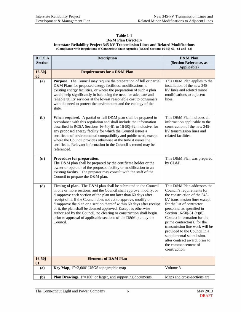
Table 1-1
D&M Plan Directory Interstate Reliability Project 345-kV Transmission Lines and Related Modifications
(Compliance with Regulations of Connecticut State Agencies [RCSA] Sections 16-50j-60, -61 and -62) R.C.S.A Section
Description D&M Plan (Section Reference, as
Applicable) 16-50j-60
Requirements for a D&M Plan
(a) Purpose. The Council may require the preparation of full or partial D&M Plans for proposed energy facilities, modifications to existing energy facilities, or where the preparation of such a plan would help significantly in balancing the need for adequate and reliable utility services at the lowest reasonable cost to consumers with the need to protect the environment and the ecology of the state.
This D&M Plan applies to the installation of the new 345-kV lines and related minor modifications to adjacent lines.
(b) When required. A partial or full D&M plan shall be prepared in accordance with this regulation and shall include the information described in RCSA Sections 16-50j-61 to 16-50j-62, inclusive, for any proposed energy facility for which the Council issues a certificate of environmental compatibility and public need, except where the Council provides otherwise at the time it issues the certificate. Relevant information in the Council’s record may be referenced.
This D&M Plan includes all information applicable to the construction of the new 345-kV transmission lines and related facilities.
(c ) Procedure for preparation. The D&M plan shall be prepared by the certificate holder or the owner or operator of the proposed facility or modification to an existing facility. The preparer may consult with the staff of the Council to prepare the D&M plan.
This D&M Plan was prepared by CL&P.
(d) Timing of plan. The D&M plan shall be submitted to the Council in one or more sections, and the Council shall approve, modify, or disapprove each section of the plan not later than 60 days after receipt of it. If the Council does not act to approve, modify or disapprove the plan or a section thereof within 60 days after receipt of it, the plan shall be deemed approved. Except as otherwise authorized by the Council, no clearing or construction shall begin prior to approval of applicable sections of the D&M plan by the Council.
This D&M Plan addresses the Council’s requirements for the construction of the 345-kV transmission lines except for the list of contractor personnel as specified in Section 16-50j-61 (c)(8). Contact information for the prime contractor(s) for the transmission line work will be provided to the Council in a supplemental submission, after contract award, prior to the commencement of construction.
16-50j-61
Elements of D&M Plan
(a) Key Map, 1”=2,000’ USGS topographic map
Volume 3
(b) Plan Drawings, 1”=100’ or larger, and supporting documents, Maps and cross-sections are

Interstate Reliability Project New 345-kV Transmission Lines and Development & Management Plan Related Minor Modifications to Adjacent Lines
The Connecticut Light and Power Company 7 May 2013 DRAFT
R.C.S.A Section
Description D&M Plan (Section Reference, as
Applicable) which shall contain the following information:
included in Volume 3.
1. Edges of the proposed site and any existing site contiguous to or crossing the site, portions of the site owned by the company in fee, and the identity of property owners of record of the portions of the site not owned by the company in fee
Volume 3 maps
2. Public roads and public land crossings or adjoining the site
Volume 3 maps
3. Location of 50’ contours along the site Volume 3 maps
4. Probable location, type, and height of the proposed facility and components (including each new transmission structure, position of guys, description of foundations, and locations of any utility or other structures to remain on the site or to be removed
Volume 3 maps and cross-sections.
5. Probable points of access to the site, and the route and likely nature of accessways, including alternatives
Volume 3 maps
6. Edges of existing and proposed clearing areas, the type of proposed clearing along each part of the site, and the location and species identification of vegetation that would remain for aesthetic and wildlife value
Volume 3 maps; Volume 1 Section 3.4 and Appendix A, Vegetation Clearing Plan
7. Identification of sensitive areas and conditions within and adjoining the site, including but not limited to:
A. Wetland and watercourse areas regulated under C.G.S. Chapter 440 and any locations where construction may create drainage problems
Volume 1, Section 5.2; Volume 3
B. Areas of high erosion potential Volume 1, Section 5.1; Volume 3
C. Critical habitats or areas identified as having rare, endangered, or threatened, or special concern plant or animal species listed by the state or federal government
Volume 1,Section 5.4; Volume 3 maps
D. Location of known underground utilities or resources to be crossed (electric lines, fuel lines, drainage systems and natural or artificial public or private water resources)
Volume 3 maps
E. Residences or businesses within or adjoining the site that may be disrupted during construction
Volume 3 maps
F. Significant environmental, historic and ecological features (significantly large or old trees, buildings, monuments, stone walls or features of local interest)
Volume 1, Section 5.10 (cultural resources);Volume 3 maps depict general locations of culturally sensitive areas
(c) Supplemental Information
1. Plans (if any) to salvage marketable timber, restore habitat and Volume 1, Section 3.4;
Interstate Reliability Project New 345-kV Transmission Lines and Development & Management Plan Related Minor Modifications to Adjacent Lines
The Connecticut Light and Power Company 8 May 2013 DRAFT
R.C.S.A Section
Description D&M Plan (Section Reference, as
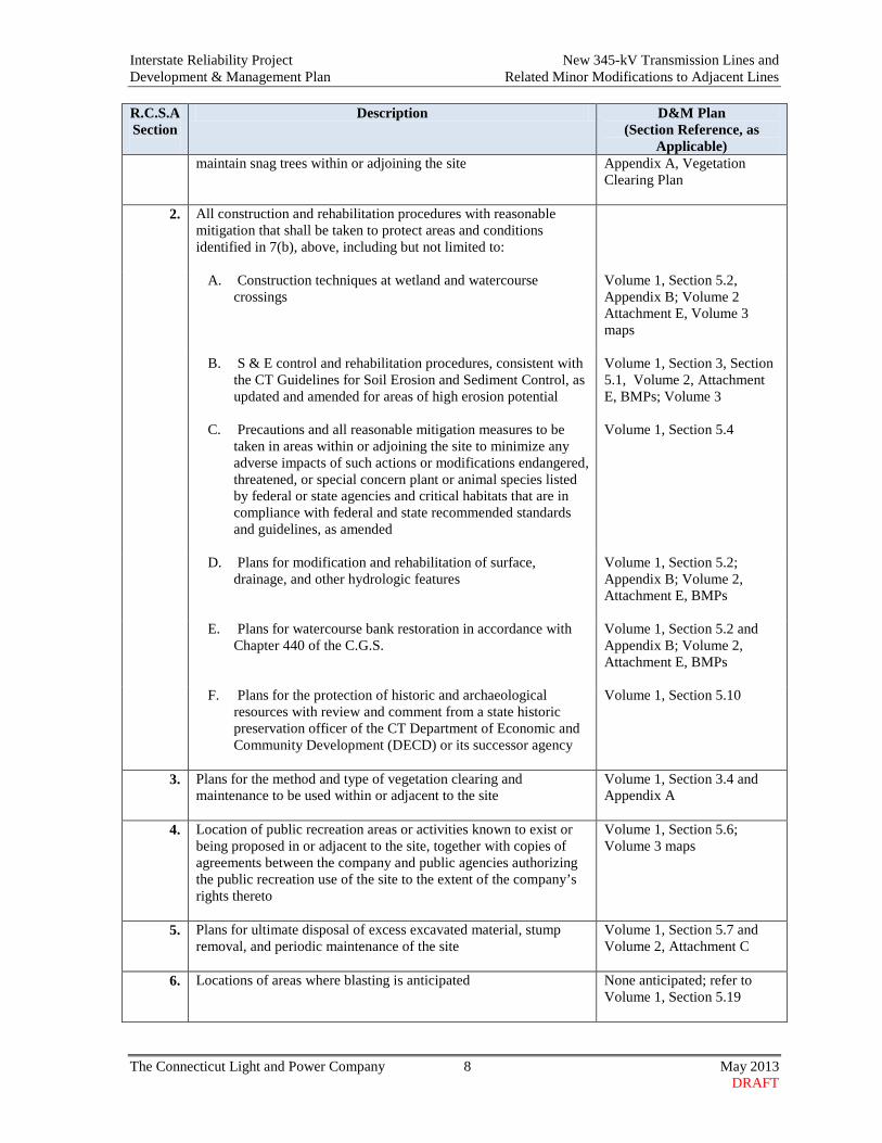
Applicable) maintain snag trees within or adjoining the site
Appendix A, Vegetation Clearing Plan
2. All construction and rehabilitation procedures with reasonable mitigation that shall be taken to protect areas and conditions identified in 7(b), above, including but not limited to:
A. Construction techniques at wetland and watercourse crossings
Volume 1, Section 5.2, Appendix B; Volume 2 Attachment E, Volume 3 maps
B. S & E control and rehabilitation procedures, consistent with the CT Guidelines for Soil Erosion and Sediment Control, as updated and amended for areas of high erosion potential
Volume 1, Section 3, Section 5.1, Volume 2, Attachment E, BMPs; Volume 3
C. Precautions and all reasonable mitigation measures to be taken in areas within or adjoining the site to minimize any adverse impacts of such actions or modifications endangered, threatened, or special concern plant or animal species listed by federal or state agencies and critical habitats that are in compliance with federal and state recommended standards and guidelines, as amended
Volume 1, Section 5.4
D. Plans for modification and rehabilitation of surface, drainage, and other hydrologic features
Volume 1, Section 5.2; Appendix B; Volume 2, Attachment E, BMPs
E. Plans for watercourse bank restoration in accordance with Chapter 440 of the C.G.S.
Volume 1, Section 5.2 and Appendix B; Volume 2, Attachment E, BMPs
F. Plans for the protection of historic and archaeological resources with review and comment from a state historic preservation officer of the CT Department of Economic and Community Development (DECD) or its successor agency
Volume 1, Section 5.10
3. Plans for the method and type of vegetation clearing and maintenance to be used within or adjacent to the site
Volume 1, Section 3.4 and Appendix A
4. Location of public recreation areas or activities known to exist or being proposed in or adjacent to the site, together with copies of agreements between the company and public agencies authorizing the public recreation use of the site to the extent of the company’s rights thereto
Volume 1, Section 5.6; Volume 3 maps
5. Plans for ultimate disposal of excess excavated material, stump removal, and periodic maintenance of the site
Volume 1, Section 5.7 and Volume 2, Attachment C
6. Locations of areas where blasting is anticipated None anticipated; refer to Volume 1, Section 5.19
Interstate Reliability Project New 345-kV Transmission Lines and Development & Management Plan Related Minor Modifications to Adjacent Lines
The Connecticut Light and Power Company 9 May 2013 DRAFT
R.C.S.A Section
Description D&M Plan (Section Reference, as
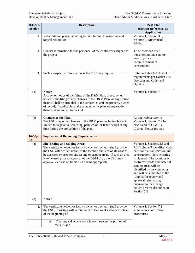
Applicable) 7. Rehabilitation plans, including but not limited to reseeding and
topsoil restoration Volume 1, Section 3.8; Volume 2, Attachment E BMPs
8. Contact information for the personnel of the contractor assigned to the project
To be provided after transmission line contract award, prior to commencement of construction.
9. Such site-specific information as the CSC may require Refer to Table 1-2: List of requirements per Docket 424 Decision and Order and Opinion
(d) Notice A copy, or notice of the filing, of the D&M Plan, or a copy, or notice of the filing of any changes to the D&M Plan, or any section thereof, shall be provided to the service list and the property owner of record, if applicable, at the same time the plan, or any section thereof, is submitted to the CSC
Volume 1, Section 7
(e) Changes to the Plan The CSC may order changes to the D&M plan, including but not limited to vegetative screening, paint color, or fence design at any time during the preparation of the plan
As applicable; refer to Volume 1, Section 7.2 for discussion of CL&P’s Change Notice process
16-50j-62
Supplemental Reporting Requirements
(a) Site Testing and Staging Areas The certificate holder, or facility owner or operator, shall provide the CSC with written notice of the location and size of all areas to be accessed or used for site testing or staging areas. If such an area is to be used prior to approval of the D&M plan, the CSC may approve such use on terms as it deems appropriate.
Volume 1, Sections 3.3 and 7.1; Volume 3 identifies work pads for the transmission line construction. No site testing is planned. The locations of contractor yards and material staging areas will be identified by the contractor and will be submitted to the Council for review and approval prior to use, pursuant to the Change Notice process described in Section 7.2
(b) Notice
1. The certificate holder, or facility owner or operator, shall provide the CSC, in writing with a minimum of two weeks advance notice of the beginning of:
Volume 1, Section 7.1 summarizes notification procedures
A. Clearing and access work in each successive portion of the site, and
Interstate Reliability Project New 345-kV Transmission Lines and Development & Management Plan Related Minor Modifications to Adjacent Lines
The Connecticut Light and Power Company 10 May 2013 DRAFT
R.C.S.A Section
Description D&M Plan (Section Reference, as
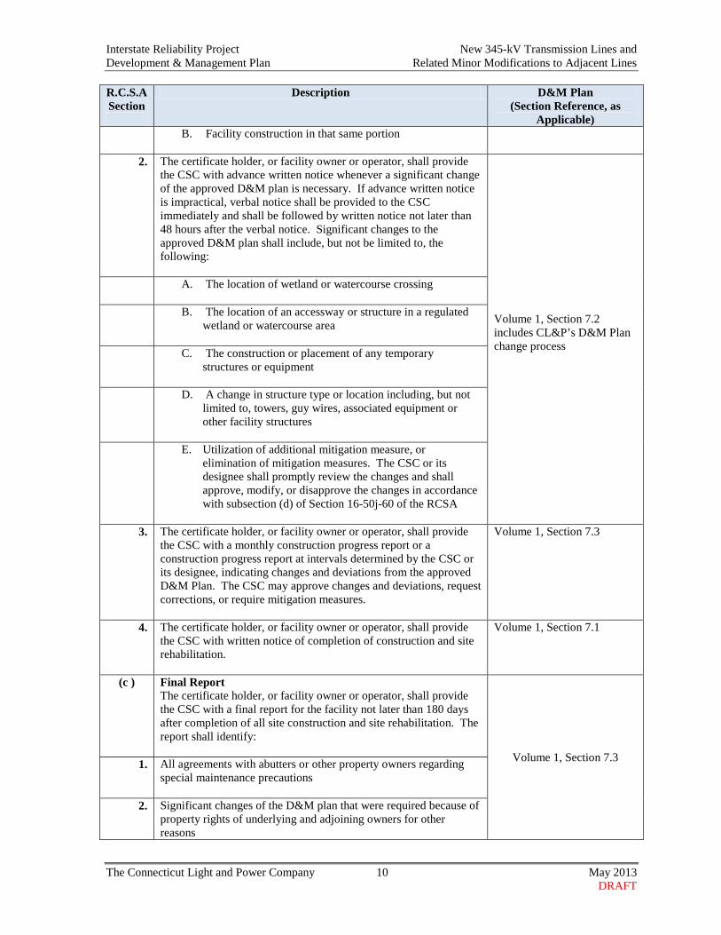
Applicable) B. Facility construction in that same portion
2. The certificate holder, or facility owner or operator, shall provide
the CSC with advance written notice whenever a significant change of the approved D&M plan is necessary. If advance written notice is impractical, verbal notice shall be provided to the CSC immediately and shall be followed by written notice not later than 48 hours after the verbal notice. Significant changes to the approved D&M plan shall include, but not be limited to, the following:
Volume 1, Section 7.2 includes CL&P’s D&M Plan change process
A. The location of wetland or watercourse crossing
B. The location of an accessway or structure in a regulated wetland or watercourse area
C. The construction or placement of any temporary structures or equipment
D. A change in structure type or location including, but not
limited to, towers, guy wires, associated equipment or other facility structures
E. Utilization of additional mitigation measure, or
elimination of mitigation measures. The CSC or its designee shall promptly review the changes and shall approve, modify, or disapprove the changes in accordance with subsection (d) of Section 16-50j-60 of the RCSA
3. The certificate holder, or facility owner or operator, shall provide
the CSC with a monthly construction progress report or a construction progress report at intervals determined by the CSC or its designee, indicating changes and deviations from the approved D&M Plan. The CSC may approve changes and deviations, request corrections, or require mitigation measures.
Volume 1, Section 7.3
4. The certificate holder, or facility owner or operator, shall provide the CSC with written notice of completion of construction and site rehabilitation.
Volume 1, Section 7.1
(c ) Final Report The certificate holder, or facility owner or operator, shall provide the CSC with a final report for the facility not later than 180 days after completion of all site construction and site rehabilitation. The report shall identify: Volume 1, Section 7.3 1. All agreements with abutters or other property owners regarding special maintenance precautions
2. Significant changes of the D&M plan that were required because of property rights of underlying and adjoining owners for other reasons

Interstate Reliability Project New 345-kV Transmission Lines and Development & Management Plan Related Minor Modifications to Adjacent Lines
The Connecticut Light and Power Company 11 May 2013 DRAFT
R.C.S.A Section
Description D&M Plan (Section Reference, as
Applicable)
3. The location of construction materials which have been left in place including, but not limited to, culverts, erosion control structures along watercourses and steep slopes, and corduroy roads in regulated wetlands
4. The location of areas where special planting and reseeding have been done
5. The actual construction cost of the facility, including but not limited to the following costs:
A. Clearing and access B. Construction of the facility and associated equipment C. Rehabilitation; and D. Property acquisition for the site or access to the site
(d) Protective Order
The certificate holder, or facility owner or operator, may file a motion for protective order pertaining to commercial or financial information related to the site or access to the site.
N/A

Interstate Reliability Project New 345-kV Transmission Lines and Development & Management Plan Related Minor Modifications to Adjacent Lines
The Connecticut Light and Power Company 12 May 2013 DRAFT
Table 1-2
D&M Plan Directory of Docket No. 424 Decision and Order and Opinion Requirements Interstate Reliability Project 345-kV Transmission Lines and Related Modifications
Condition
or Page Number
Description
D&M Plan (Section Reference, as
Applicable)
Condition Number Decision and Order
(1) The Certificate Holder shall construct the proposed transmission line overhead along the Interstate route with potential route and/or configuration variations noted under Condition numbers 3(p) and 3(q) of this Decision and Order. The new transmission line shall be placed primarily on H-frame structures except in Segment 9 between Lake Road Junction and Lake Road Switching Station in Killingly where the existing and proposed lines would be supported on vertical steel structures; and in the areas of the federally-owned Mansfield Hollow property and Hawthorne Lane Alternative, details of which shall be submitted prior to construction as noted below. Also, structure #39 on the property of Highland Ridge Golf Range shall be constructed as a steel monopole
Volume 1, Section 3, and Volume 3 The Volume 3 maps and cross-sections identify structure configurations. (The steel monopole structure on the Highland Ridge Golf Range also is designated as NU Structure No. 10739.)
(2) The Certificate Holder shall construct the additions to Card Street Substation, Lake Road Switching Station, and Killingly Substation, as proposed.
Refer to separate D&M Plan for modifications to the switching station and substations
(3) The Certificate Holder shall prepare a Development and Management (D&M) Plan, whole or in parts, for this project in compliance with Sections 16-50j-60 through 16-50j-62 of the Regulations of Connecticut State Agencies. The D&M Plan shall be served on the Towns of Lebanon, Columbia, Coventry, Mansfield, Chaplin, Hampton, Brooklyn, Pomfret, Killingly, Putnam and Thompson for comment, and all parties and intervenors as listed in the service list, and submitted to and approved by the Council prior to the commencement of facility construction and shall include:
Refer to Volume 1, Section 8; Volume 2, Attachment I (Agency Correspondence and Public Outreach Documentation)
a. A detailed site plan showing the placement of the access roads, structure foundations, equipment and material staging areas for the overhead route;
Volume 3 maps
b. An erosion and sediment control plan, consistent with the 2002 Connecticut Guidelines for Soil Erosion and Sediment Control as amended;
Volume 1, Section 5.1; Volume 2, Attachment E, BMPs
c. A spill prevention and countermeasures plan;
Volume 2, Attachment B
d. Provisions for crossing inland wetland and watercourses for the route;
Volume 1, Section 5.2 and Appendix B; Volume 2, Attachment E, BMPs; Volume 3 maps
e. Details of ground disturbance; Volume 3 maps

Interstate Reliability Project New 345-kV Transmission Lines and Development & Management Plan Related Minor Modifications to Adjacent Lines
The Connecticut Light and Power Company 13 May 2013 DRAFT
Condition or Page Number
Description
D&M Plan (Section Reference, as
Applicable)
f. Vegetative clearing plan;
Volume 1, Appendix A
g. A wetland restoration plan;
Volume 1, Section 5.2 and Appendix B
h. Invasive species control plan;
Volume 1, Appendix D
i. Provisions to manage the discovery of undocumented Native American Archaeological resources;
Volume 1, Section 5.10
j. A post-construction electric and magnetic field monitoring plan;
Volume 1, Section 5.17 and Appendix F
k. A schedule of construction hours during nights and/or weekends and mitigation of lighting and noise;
Volume 1, Section 4, Section 5.8
l. A plan to minimize air quality effects during construction;
Volume 1, Section 5.5
m. A blasting plan, if necessary;
Volume 1, Section 5.19
n. Identification of developed areas for staging and equipment lay down, field office trailers, sanitary facilities and parking before establishing a new area;
Volume 1, Section 3.2; Volume 3 maps depict work pads; contractor yards and material staging sites to be provided to the Council later for review and approval
o. Plans and strategies to prevent the use of the right-of-way by all-terrain vehicles;
Volume 1, Section 5.14
p. Details of the configuration of the line structures within the federally-owned Mansfield Hollow State Park and Wildlife Management Area;
Volume 1, Section 5.6.2, Volume 3 (maps 15-19) and XS-3, XS-5
q. Details of the route and line configuration for the segment of the line that crosses Hawthorne Lane in Mansfield; and
Volume 1, Section 5.18; Volume 3 maps and XS-HL-1
r. Details of protection measures for active farmland, including a report of consultations with the owners of agricultural properties to identify active farmland and assess protection of agricultural soils.
Volume 1, Appendix C, Report of Consultations with Farmland Property Owners and Lessees
(4) The Certificate Holder shall comply with the Department of Energy and Environmental Protection recommendations, or coordinate with the Department of Energy and Environmental Protection, for construction of the route in the area of endangered, threatened, or special concern species identified along the Interstate route in Connecticut.
Volume 1, Section 5.4
(5) The Certificate Holder shall conform to the Council’s Best Project represents BMPs
Interstate Reliability Project New 345-kV Transmission Lines and Development & Management Plan Related Minor Modifications to Adjacent Lines
The Connecticut Light and Power Company 14 May 2013 DRAFT
Condition or Page Number
Description
D&M Plan (Section Reference, as
Applicable)
Management Practices for Electric and Magnetic Fields.
for EMF, per Council D&O
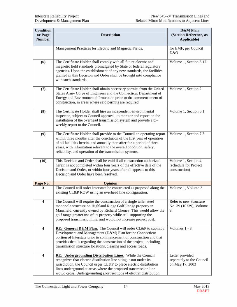
(6) The Certificate Holder shall comply with all future electric and magnetic field standards promulgated by State or federal regulatory agencies. Upon the establishment of any new standards, the facilities granted in this Decision and Order shall be brought into compliance with such standards.
Volume 1, Section 5.17
(7) The Certificate Holder shall obtain necessary permits from the United States Army Corps of Engineers and the Connecticut Department of Energy and Environmental Protection prior to the commencement of construction, in areas where said permits are required.
Volume 1, Section 2
(8) The Certificate Holder shall hire an independent environmental inspector, subject to Council approval, to monitor and report on the installation of the overhead transmission system and provide a bi-weekly report to the Council.
Volume 1, Section 6.1
(9) The Certificate Holder shall provide to the Council an operating report within three months after the conclusion of the first year of operation of all facilities herein, and annually thereafter for a period of three years, with information relevant to the overall condition, safety, reliability, and operation of the transmission systems.
Volume 1, Section 7.3
(10) This Decision and Order shall be void if all construction authorized herein is not completed within four years of the effective date of the Decision and Order, or within four years after all appeals to this Decision and Order have been resolved.
Volume 1, Section 4 (schedule for Project construction)
Page No. Opinion 3 The Council will order Interstate be constructed as proposed along the
existing CL&P ROW using an overhead line configuration.
Volume 1, Volume 3
4 The Council will require the construction of a single taller steel monopole structure on Highland Ridge Golf Range property in Mansfield, currently owned by Richard Cheney. This would allow the golf range greater use of its property while still supporting the proposed transmission line, and would not increase project cost.
Refer to new Structure No. 39 (10739), Volume 3
4 RE: General D&M Plan. The Council will order CL&P to submit a Development and Management (D&M) Plan for the Connecticut portion of Interstate prior to commencement of construction and that provides details regarding the construction of the project, including transmission structure locations, clearing and access roads.
Volumes 1 - 3
4 RE: Undergrounding Distribution Lines. While the Council recognizes that electric distribution line siting is not under its jurisdiction, the Council urges CL&P to place electric distribution lines underground at areas where the proposed transmission line would cross. Undergrounding short sections of electric distribution
Letter provided separately to the Council on May 17, 2003

Interstate Reliability Project New 345-kV Transmission Lines and Development & Management Plan Related Minor Modifications to Adjacent Lines
The Connecticut Light and Power Company 15 May 2013 DRAFT
Condition or Page Number
Description
D&M Plan (Section Reference, as
Applicable)
lines would reduce visual impact associated with the crossing at a similar cost.
5 Re: Mansfield Hollow. Without deference to Connecticut ratepayers, USACE indicated a preference for the 4.8-acre Minimal ROW expansion option. However, there is currently no official decision of USACE. Therefore, the Council will order that the 345-kV route be approved through the federally-owned property but that the final configuration of the structures and lines is determined in the D&M Plan phase of the docket.
Volume 1, Section 5.6.2; Volume 3 maps, XS-3 and XS-5
6 Re: Hawthorne Lane Alternative Option. The Council finds that the Hawthorne Lane Alternative is a well thought out plan with minimal adverse impact. The Council will leave the final decision on this portion of Interstate to the D&M Plan.
Volume 1, Section 5.18; Volume 3 (maps and XS-HL-1)
9 RE: Grading, Filling, and Site Restoration. The Council will require the inclusion of grading and filling details in the D&M Plan for Interstate, with the aim of restoring as many areas as possible to pre-construction conditions following the installation of transmission structures and lines.
Volume 1, Section 3; Volume 3
9 RE: Agricultural Soils Protection. The Council will order CL&P to address in its D&M Plan the protection of valuable agricultural soils, whether by consulting with landowners who actively farm the ROW, or, elsewhere along the ROW, by working with state or regional agencies to identify valuable soils and manage their disposition appropriately during construction.
Volume 1, Appendix C; Volume 3 maps
9 RE: Wetland Impacts. The Council will require that the D&M Plan for Interstate provide detailed plans showing all wetland impacts. On the basis of this detail, the Council may require further wetlands mitigation, which may include compensatory options, under the jurisdiction of DEEP.
Volume 1, Section 5.2 and Appendix B; Volume 3 maps and water resource impact table
9 RE: Wetlands and Watercourses. The primary temporary impacts would be potential erosion and sedimentation into wetlands and watercourses during construction of transmission structures and access roads. Other temporary impacts include possible fuel spills into wetlands and watercourses from the operation of construction equipment, and possible adverse effects on wetlands and watercourses from temporary vegetative clearing related to construction. The Council will require that the D&M Plan include specific programs to minimize all such temporary impacts and to restore areas affected by such temporary impacts as much as possible to their pre-construction condition. Further with that aim, the Council will order that an environmental inspector be hired to monitor compliance with the D&M Plan during construction and to monitor restoration for a period afterward.
Volume 1, Sections 3.8, 5.1, 5.2, and 6.1, Appendices A, B, D, and E,; Volume 2, Attachments B, C, D, and E; Volume 3
10 RE: Vegetation. The Council will order an Invasive Species Control Volume 1, Appendix D

Interstate Reliability Project New 345-kV Transmission Lines and Development & Management Plan Related Minor Modifications to Adjacent Lines
The Connecticut Light and Power Company 16 May 2013 DRAFT
Condition or Page Number
Description
D&M Plan (Section Reference, as
Applicable)
Plan for the project, developed in consultation with the USACE, DEEP and other agencies. This plan shall identify measures for controlling invasive plants listed on the Connecticut Invasive Plant List – October 2011. Also, through conditions to be applied in the D&M Plan, the Council will encourage the continuance of vegetative maintenance practices, including those related to herbicide application and to invasive species that protect native plants and wildlife.
10 RE: Lepidoptera. Mitigation to minimize impact to Lepidoptera involves maintaining its habitat. Lepidoptera host plant communities were found along the ROW. CL&P would install exclusion fencing to protect plant communities. If exclusion fencing is not feasible, mitigation would include avoiding permanent impact to important vegetative areas to the extent practicable; limiting construction to existing dirt access roads; creating a Vegetation Management Plan to reduce potential colonization by invasive species and promote the growth of native host plant species; and performing additional rare species surveys along certain areas of the ROWs.
Volume 1, Section 5.4; Volume 3 maps
10 RE: Wood Turtle. The Council will order that CL&P comply with DEEP recommendations, to the extent feasible, for wood turtles, including: minimizing the removal of low-growth vegetation in areas adjacent to rivers/streams documented to support wood turtles; using erosion and sedimentation controls to minimize the deposition of sediment into wetland areas and to preclude wood turtles from accessing active construction areas; and ensuring construction contractors are able to identify wood turtles and know proper handling and care procedures if one is encountered. Also, a DEEP-approved turtle monitor would be present during construction in wood turtle habitats. If found, wood turtles would be removed from the active area and placed in the direction they were moving. RE: Eastern Hognose Snake. The eastern hognose snake and eastern ribbon snake are state-listed species identified as potentially occurring near portions of the proposed route. Both snake species are typically dormant from November 1 through April 1. The Council will order that CL&P comply with DEEP recommendations, to the extent feasible, for the eastern hognose snake and eastern ribbon snake, including: training construction contractors to identify the snakes properly handle and care for the snakes if encountered; and maintaining the presence of a DEEP-approved snake monitor during construction. Any snakes that are encountered would be removed from the active workspace.
Volume 1, Section 5.4 (Note: CT DEEP does not require special protection measures for wood turtles, which have not been found along the Project ROWs. Protocols for the protection of state-listed species observed in the vicinity of the ROWs [including the Eastern hognose snake] are included in Section 5.4.)
11 RE: Noise and Air Quality. Operation of the Interstate lines will not be a significant source of audible noise. Any noise from heavy machinery during construction of Interstate would be short-term. The Council will condition the D&M Plan, however, to schedule construction periods during reasonable day-time hours. Operation of the transmission lines would not impact air quality. Air quality effects from constructing Interstate would be temporary. The
Volume 1, Sections 5.5 and 5.8
Interstate Reliability Project New 345-kV Transmission Lines and Development & Management Plan Related Minor Modifications to Adjacent Lines
The Connecticut Light and Power Company 17 May 2013 DRAFT
Condition or Page Number
Description
D&M Plan (Section Reference, as
Applicable)
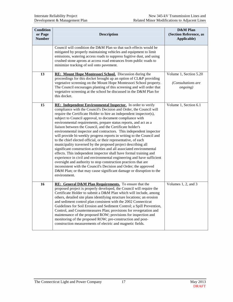
Council will condition the D&M Plan so that such effects would be mitigated by properly maintaining vehicles and equipment to limit emissions, watering access roads to suppress fugitive dust, and using crushed stone aprons at access road entrances from public roads to minimize tracking of soil onto pavement.
13 RE: Mount Hope Montessori School. Discussion during the proceedings for this docket brought up an option of CL&P providing vegetative screening on the Mount Hope Montessori School property. The Council encourages planting of this screening and will order that vegetative screening at the school be discussed in the D&M Plan for this docket.
Volume 1, Section 5.20
(Consultations are ongoing)
15 RE: Independent Environmental Inspector. In order to verify compliance with the Council's Decision and Order, the Council will require the Certificate Holder to hire an independent inspector(s), subject to Council approval, to document compliance with environmental requirements, prepare status reports, and act as a liaison between the Council, and the Certificate holder's environmental inspector and contractors. This independent inspector will provide bi-weekly progress reports in writing to the Council and to the chief elected official, or their representative, of each municipality traversed by the proposed project describing all significant construction activities and all associated environmental effects. This independent inspector shall have formal training and experience in civil and environmental engineering and have sufficient oversight and authority to stop construction practices that are inconsistent with the Council's Decision and Order; the approved D&M Plan; or that may cause significant damage or disruption to the environment.
Volume 1, Section 6.1
16 RE: General D&M Plan Requirements. To ensure that the proposed project is properly developed, the Council will require the Certificate Holder to submit a D&M Plan which will include, among others, detailed site plans identifying structure locations; an erosion and sediment control plan consistent with the 2002 Connecticut Guidelines for Soil Erosion and Sediment Control; a Spill Prevention, Control, and Countermeasures Plan; provisions for revegetation and maintenance of the proposed ROW; provisions for inspection and monitoring of the proposed ROW; pre-construction and post-construction measurements of electric and magnetic fields.
Volumes 1, 2, and 3

Interstate Reliability Project New 345-kV Transmission Lines and Development & Management Plan Related Minor Modifications to Adjacent Lines
The Connecticut Light and Power Company 18 May 2013 DRAFT
This page intentionally left blank

Interstate Reliability Project New 345-kV Transmission Lines and Development & Management Plan Related Minor Modifications to Adjacent Lines
The Connecticut Light and Power Company 19 May 2013 DRAFT
2. REGULATORY APPROVALS AND CONSULTATIONS
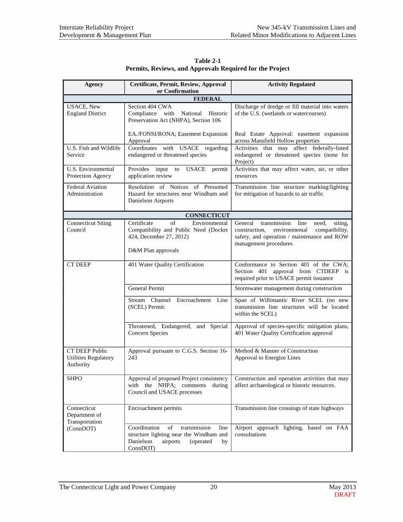
2.1 REGULATORY APPROVALS AND REQUIREMENTS This D&M Plan conforms to the specifications of Sections 16-50j-60 through 16-50j-62 of the RCSA (Requirements for a D&M Plan, Elements of a D&M Plan, Reporting Requirements); incorporates CL&P’s commitments as contained in the record of the Council’s Docket 424 regulatory process; and reflects adherence to the conditions of the Council’s certificate for the Project and other relevant, anticipated regulatory approvals. The federal and state permits and approvals needed for the Project are listed in Table 2-1. Copies of the Council’s approval and CT DEEP permits are provided in Volume 2, including:
• The Council’s Decision and Order and Opinion for the Project (refer to Volume 2, Attachment A);
• The CT DEEP General Permit for the Discharge of Stormwater and Dewatering
Wastewaters Associated with Construction Activities, which applies to the management of the discharge of stormwater and dewatering wastewaters from construction sites (Volume 2, Attachment F); and
• The CT DEEP Stream Channel Encroachment Line Permit and Section 401 Water Quality Certification (Volume 2, Attachment G).
2.2 CONSULTATIONS During the preparation of this D&M Plan, CL&P consulted with representatives of the 11 towns traversed by the 345-kV transmission lines, as well as with representatives of various state and federal agencies, including the USACE, CT DEEP, State Historic Preservation Office (SHPO)2, and Connecticut Department of Agriculture. In addition, CL&P contacted property owners along the transmission line ROWs, including owners of active farmlands. During consultations with town representatives, property owners, and the interested public, CL&P provided information regarding the D&M Plan process, the planned transmission line construction activities, and CL&P’s outreach procedures and points-of-contact prior to and during construction. Additional information regarding CL&P’s public outreach process is included in Section 8 and in Volume 2, Attachment I. The results of CL&P’s consultations with property owners and lessees of active farmlands located along the transmission line ROWs are summarized in Appendix C of this Volume.
2 For the review of this Project, the Office of State Archaeology (OSA) is representing the SHPO.
Interstate Reliability Project New 345-kV Transmission Lines and Development & Management Plan Related Minor Modifications to Adjacent Lines
The Connecticut Light and Power Company 20 May 2013 DRAFT
Table 2-1
Permits, Reviews, and Approvals Required for the Project
Agency Certificate, Permit, Review, Approval or Confirmation
Activity Regulated
FEDERAL USACE, New England District
Section 404 CWA Compliance with National Historic Preservation Act (NHPA), Section 106 EA./FONSI/RONA; Easement Expansion Approval
Discharge of dredge or fill material into waters of the U.S. (wetlands or watercourses) Real Estate Approval: easement expansion across Mansfield Hollow properties
U.S. Fish and Wildlife Service
Coordinates with USACE regarding endangered or threatened species
Activities that may affect federally-listed endangered or threatened species (none for Project)
U.S. Environmental Protection Agency
Provides input to USACE permit application review
Activities that may affect water, air, or other resources
Federal Aviation Administration
Resolution of Notices of Presumed Hazard for structures near Windham and Danielson Airports
Transmission line structure marking/lighting for mitigation of hazards to air traffic
CONNECTICUT Connecticut Siting Council
Certificate of Environmental Compatibility and Public Need (Docket 424, December 27, 2012) D&M Plan approvals
General transmission line need, siting, construction, environmental compatibility, safety, and operation / maintenance and ROW management procedures
CT DEEP 401 Water Quality Certification
Conformance to Section 401 of the CWA; Section 401 approval from CTDEEP is required prior to USACE permit issuance
General Permit Stormwater management during construction
Stream Channel Encroachment Line (SCEL) Permit:
Span of Willimantic River SCEL (no new transmission line structures will be located within the SCEL)
Threatened, Endangered, and Special Concern Species
Approval of species-specific mitigation plans, 401 Water Quality Certification approval
CT DEEP Public Utilities Regulatory Authority
Approval pursuant to C.G.S. Section 16-243
Method & Manner of Construction Approval to Energize Lines
SHPO Approval of proposed Project consistency with the NHPA; comments during Council and USACE processes
Construction and operation activities that may affect archaeological or historic resources.
Connecticut Department of Transportation (ConnDOT)
Encroachment permits
Transmission line crossings of state highways
Coordination of transmission line structure lighting near the Windham and Danielson airports (operated by ConnDOT)
Airport approach lighting, based on FAA consultations
Interstate Reliability Project New 345-kV Transmission Lines and Development & Management Plan Related Minor Modifications to Adjacent Lines
The Connecticut Light and Power Company 21 May 2013 DRAFT
CL&P consulted with federal and state agencies both as part of permitting efforts and as part of the preparation of resource-specific protection measures included in this D&M Plan. For example, CL&P coordinated with the Connecticut Department of Agriculture regarding the Project’s outreach to property owners and lessees of active farmlands and farmland protection measures (refer to Appendix C) and with the CT DEEP regarding threatened and endangered species. In addition, as specified in the D&M Plan requirements, RCSA Section 16-50j-61(c)(2)(F), CL&P consulted with the SHPO (OSA) regarding the potential effects of the 345-kV transmission line construction on significant archaeological or historic resources and the measures to mitigate such effects, as necessary. Correspondence received to date from the SHPO and other agencies concerning the transmission line construction activities is included in Volume 2, Attachment I. Consultations Regarding the Mansfield Hollow Area Subsequent to the issuance of the Council’s Decision and Order approving the Project, CL&P completed negotiations with the USACE regarding the expansion of CL&P’s existing 150-foot-wide easement across two segments of federally owned lands, totaling approximately 1.4 miles. The two federally owned segments traversed by CL&P’s ROW are among 2,300 acres that the USACE leases to the CT DEEP, which manages the property as Mansfield Hollow State Park, Mansfield Hollow Lake, and Mansfield Hollow Wildlife Management Area (WMA). The property is collectively referred to as “the Mansfield Hollow area”. CL&P’s existing 150-foot-wide ROW extends across approximately 0.9 mile of federal lands in the Town of Mansfield (Mansfield Hollow State Park and WMA) and 0.5 mile in the Town of Chaplin (WMA). To accommodate the new 345-kV line adjacent to the existing 345-kV line while maintaining required clearances between conductors and vegetation, CL&P proposed to expand the easement on federal property by 25 feet to the north in Mansfield and by 35 feet to the north in Chaplin. This easement expansion totals approximately 5 acres, including 2.6 acres in Mansfield and 2.4 acres in Chaplin. In accordance with the National Environmental Policy Act, in November 2012, the USACE prepared and issued for public review and comment a draft Environmental Assessment (EA) / Finding of No Significant Impact (FONSI) / Record of Non-Applicability (RONA) that evaluated the proposed 5-acre easement expansion and alternatives, and found that the 5-acre easement expansion would not adversely affect the environment. After receiving no comments on the draft EA/FONSI/RONA during the public review period, the USACE finalized the EA/FONSI/RONA in January 2013 and, on February 5, 2013, issued the signed FONSI, endorsing the 5-acre easement expansion. The USACE is proceeding with the preparation of documentation for the conveyance to CL&P of the additional 5-acre easement. CL&P anticipates that this conveyance will be issued in conjunction with the USACE Section 404 Clean Water Act permit for the Project. Pursuant to the USACE’s approval of the approximately 5-acre easement expansion and in accordance with the Council’s Decision and Order, Condition 3(p), CL&P has incorporated in this

Interstate Reliability Project New 345-kV Transmission Lines and Development & Management Plan Related Minor Modifications to Adjacent Lines
The Connecticut Light and Power Company 22 May 2013 DRAFT
D&M Plan details of the transmission line configurations within the federally-owned lands in the Mansfield Hollow area (refer to Section 5.6.2, and Volume 3, XS-3 and XS-5, maps 15-19). Consultations Regarding the Hawthorne Lane ROW Shift After the issuance of the Council’s Decision and Order approving the Project, CL&P also completed negotiations with private landowners in the Hawthorne Lane area of the Town of Mansfield. As a result of these negotiations, the landowners granted CL&P new easement rights to allow a shift in the ROW that will place the new and existing transmission lines farther from four homes. Pursuant to the Council’s Decision and Order, Condition (3q), details regarding the route and line configuration for the Hawthorne Lane ROW Shift are described in Section 5.18 and illustrated in Volume 3 (refer to map 15 and XS-HL-1).

Interstate Reliability Project New 345-kV Transmission Lines and Development & Management Plan Related Minor Modifications to Adjacent Lines
The Connecticut Light and Power Company 23 May 2013 DRAFT
3. GENERAL CONSTRUCTION PROCEDURES
This section describes the construction procedures for the new 345-kV transmission lines (Sections 3.1 through 3.8) and for the related minor modifications to adjacent lines (Section 3.9). Each new 345-kV transmission line will be installed adjacent to an existing 345-kV transmission line, and along some ROW segments, also adjacent to existing 115-kV and 69-kV transmission lines and 23-kV distribution lines. In most areas, the new 345-kV line conductor will be horizontally arranged and supported by multi-pole steel-pole structures (H-frame family). Steel monopole structures will be used in certain locations, such as at the Highland Ridge Golf Range, the Hawthorne Lane and Mansfield Hollow areas (in the Town of Mansfield), between Lake Road Junction and Lake Road Switching Station (in the Town of Killingly), and at a few ROW angles where the line conductors will be supported in vertical or delta configurations. Volume 3 identifies the characteristics of each new 345-kV line structure and includes plan view drawings of each of the structure types that will be used on the Project. The new 345-kV lines will be installed using a sequential, phased, construction approach. This section summarizes the typical overhead transmission line construction activities and identifies plans and procedures that will apply to all such work. Additional special construction procedures and/or mitigation measures, as described in Section 5 and in appendices to this volume as well as in Volume 2, Attachments B through H, will be implemented to:
• Protect, or minimize impacts to, environmental resources (such as active farmlands, water resources, state-listed threatened endangered species, public recreational areas, archaeological sites);
• Limit construction-related effects on the public (noise and lighting mitigation, air quality
protection);
• Address additional construction work that will be performed to install and power aviation warning lights, in accordance with FAA requirements, on specific transmission line structures; and
• Provide further information as requested by the Council (e.g., details of protection measures
for active farmlands, the route and line configuration in the Hawthorne Lane area in the Town of Mansfield, the configuration of the line structures within the federally-owned Mansfield Hollow area in the towns of Mansfield and Chaplin, and vegetative screening at the Mount Hope Montessori School).
The Volume 3 maps include site-specific information regarding transmission line structure characteristics (i.e., structure number, type, height, finish, and foundation), environmental features

Interstate Reliability Project New 345-kV Transmission Lines and Development & Management Plan Related Minor Modifications to Adjacent Lines
The Connecticut Light and Power Company 24 May 2013 DRAFT
along the ROWs, property owners, construction work areas, and the locations where special resource protection measures will be implemented. 3.1 CONSTRUCTION MANAGEMENT AND CONTACT INFORMATION CL&P expects to award a contract for the transmission line work in late 2013. After contract award but prior to the commencement of the transmission line construction, CL&P will provide the Council with contact information for the prime construction contractor, consisting of the name of the firm, name of primary contact, corporate address, telephone number, and e-mail. The Project transmission line construction will be overseen by personnel from CL&P and CL&P’s construction manager, Burns & McDonnell Engineering (BMcD), as well as subconsultants to CL&P and BMcD. BMcD supervisory personnel will directly monitor construction activities, including adherence to engineering, safety, and environmental requirements, and will manage other subconsultants involved in monitoring construction activities. 3.2 GENERAL CONSTRUCTION SEQUENCE: OVERVIEW CL&P will construct the proposed transmission lines in several stages, some overlapping in time. The following summarizes the sequence of activities for the construction of the overhead transmission lines:
• Prepare material staging sites (e.g., storage, staging and laydown areas) to support the construction effort.
• Establish construction field office area(s), typically including space for an office trailer, equipment storage and maintenance, sanitary facilities, and parking.
• Survey and stake the ROW boundaries (where necessary), vegetation clearing boundaries, and new structure locations.
• Mark the boundaries of previously delineated wetland and watercourse areas, including vernal pools.
• Identify and mark areas to be avoided (e.g., sensitive cultural or environmental resource areas).
• Identify other areas, as appropriate, where special construction considerations will apply (e.g., active farmlands, where the farmland protection measures will be implemented).
• Perform vegetation clearing.
• Install erosion and sedimentation controls.
• Construct new access roads or improve existing roads. Prepare level work pads as necessary at new structure sites and conductor pulling sites.
• Construct foundations and erect/assemble new structures.
• Install shield wires and conductors.

Interstate Reliability Project New 345-kV Transmission Lines and Development & Management Plan Related Minor Modifications to Adjacent Lines
The Connecticut Light and Power Company 25 May 2013 DRAFT
• Install structure grounding systems, including counterpoise (where needed).
• Remove temporary roads and construction debris and restore disturbed sites.
• Maintain temporary erosion and sediment controls until vegetation is re-established or disturbed areas are otherwise stabilized.
3.3 CONSTRUCTION FIELD OFFICES, CONTRACTOR YARDS, AND
STAGING AREAS To support the construction of the new 345-kV transmission lines, construction field offices, contractor yards, and staging areas (including equipment and material staging sites, temporary storage areas, and laydown areas) will be required. These sites typically will be 2 to 5 acres. The preferred locations for temporary storage and staging sites are on CL&P property, along or in the general vicinity of the ROWs. If CL&P property is not suitable, previously developed lands (e.g., parking lots) or vacant land will be considered. The Project construction contractor will be responsible for identifying proposed locations for contractor yards, field construction offices, and staging areas, and for entering into agreements with the property owner for the use of such sites during construction. In accordance with the Change Notice Approval Process described in Section 7.2, the proposed locations of these construction support areas will be submitted to the Council staff for review and approval. 3.4 VEGETATION REMOVAL Vegetation removal, the first step in the preparation of the ROW for construction, will be performed as described in the Vegetation Clearing Plan (refer to Appendix A). The Volume 3 maps identify vegetation clearing limits for construction along the ROWs. Within these limits, tall-growing tree species will be removed to meet the established minimum vegetation clearances from the new transmission line conductors. Along presently un-managed portions of the ROWs, the vegetation removal limits also represent the “new edge of ROW vegetation management” as illustrated on the cross-sections in Volume 3 Within the vegetation clearing limits for construction, other types of vegetation (e.g., shrubland) also will be removed as needed for transmission line construction. Some clearing thus will be performed within presently managed portions of the ROWs. Outside of the vegetation clearing limits shown on the Volume 3 maps, trees and herbaceous or low-growing scrub/shrub species will only be cleared as needed to facilitate Project construction activities along on- and off-ROW access roads. Further, after initial vegetation removal (particularly after the new conductors are installed), trees adjacent to cleared areas may need to be selectively removed or pruned to achieve clearances from conductors.

Interstate Reliability Project New 345-kV Transmission Lines and Development & Management Plan Related Minor Modifications to Adjacent Lines
The Connecticut Light and Power Company 26 May 2013 DRAFT
Temporary erosion and sedimentation controls may be installed before vegetation removal, depending on site-specific characteristics. After vegetation removal, soil erosion and sedimentation controls typically will be installed around work limits (e.g., access roads, crane pads) in or near wetlands, streams, and other water resources. (Refer to the typical drawings of erosion and sedimentation control measures in the BMP Manual [Volume 2, Attachment E] and in Volume 3.) In addition, during this phase of construction, exclusion fencing or other types of boundary markings will typically be installed to demarcate areas of restricted construction access or environmental or cultural sensitivity. 3.5 ACCESS ROADS AND WORK PADS 3.5.1 Access Roads On-ROW access roads will provide the principal means for equipment and material to reach transmission line structure locations. The locations of existing and planned on-ROW access roads (including alternative road alignments) are illustrated on the Volume 3 maps. In some areas, to avoid traversing along the ROWs over rugged terrain or through sensitive environmental or cultural resources, access roads to the ROW will be developed across private property or across land owned by CL&P (“off-ROW access roads”). The Volume 3 maps illustrate potential off-ROW access roads and identify the property owner, parcel (line list) number, and the public road from which the road will provide access to the ROW. Table 3-1 lists the potential off-ROW access roads. CL&P has initiated discussions with the applicable private landowners seeking the rights to use such off-ROW access roads and has, in some cases, completed environmental and cultural resource field reviews to evaluate the potential impacts that would occur from the use of these access roads. If CL&P cannot obtain the rights to an off-ROW access road, either an on-ROW access road will be used or an alternative off-ROW access road will be investigated. To support the heavy construction equipment required to install 345-kV transmission line structures and foundations, all access roads (on- or off-ROW) must be sufficiently wide, with a stable base and grades that typically must be 10% or less. Access roads will have a typical 16-to-20-foot-wide travel way and, overall, a 20-to-25-foot-wide footprint (including road shoulders). However, access road widths will vary depending on site-specific conditions (principally slope and presence of wetlands) and on factors such as the amount of grading (cutting and filling) required and on whether a particular section of road must accommodate equipment turning radii and/or equipment passing/turn-out locations.

Interstate Reliability Project New 345-kV Transmission Lines and Development & Management Plan Related Minor Modifications to Adjacent Lines
The Connecticut Light and Power Company 27 May 2013 DRAFT
Table 3-1 Off-ROW Access Roads
Town / Volume 3 Map No. Line List No. Off-ROW Access Road No.
(Nearest Transmission Line Structure) Lebanon
1 3001 4 Columbia
4 30041 22 5 30046, 30047 23
Coventry 26 30056, 30057, 30058 26
Mansfield 7 30081 35, 36 8 30089 39 8 30090.01, 30090.02 41
10 30108 51 10 30109 54, 55 11 30111.01, 30114, 3011.01, 30111.02 57 14 30127, 30131 72 14 30138, 30139, 30134, 30140 75 14 30140 76 15 30146 78 15 30151 79 15 30155 80 15 30159 81 15 30163 82, 83
Chaplin 20, 21 30213 107, 110
21 30219 113 23 30226 120
Hampton 24 30243 126, 128 29 30263 152
Brooklyn 33 30285, 30287 172 36 30316 187 36 30318 189 39 30335, 30336 201, 202 39 30337 203, 204
39, 39A 30339, 20229.01 204 40 30340 208, 209, 210 41 30342 210 41 30343 212
43, 44 30368 220, 221, 222 Pomfret
46. 47 30380 236, 237, 238 Killingly
47, 47A, 48 30390 240, 241 48 30389 241 50 30409.02, 30411 254 53 30420 264
53, 54 31004 269 Putnam
51 30413.01 258 56, 57 31024 284, 285
60 31064, 31065 303 62 31086 312 62 31090 315 63 31094 318
Thompson 63 31097.01 318

Interstate Reliability Project New 345-kV Transmission Lines and Development & Management Plan Related Minor Modifications to Adjacent Lines
The Connecticut Light and Power Company 28 May 2013 DRAFT
CL&P’s existing access roads for maintaining the existing lines that occupy the ROWs will have to be upgraded and widened for the new transmission line construction. Access road improvements typically will include removing adjacent vegetation and widening roads as needed to provide a minimal travel width (additional width will be necessary as discussed above). Access roads in upland areas will likely be improved by installing clean processed rock and/or gravel. In some locations, particularly on steep slopes and at intersections with public roads, asphalt millings will be used to improve road stability and vehicle traction. CL&P also will require the construction contractor to use BMPs (refer to Attachment B, Volume 2) as warranted by site-specific conditions to maintain access road stability and minimize the potential for erosion and sedimentation. Where access roads traverse streams or wetlands, special construction procedures involving the use of culverts, timber mats (or equivalent) will be used. Existing culverted crossings may also be improved. (Refer to the Wetlands and Waterbodies Avoidance and Minimization Protocols in Appendix B). Within and near wetlands and watercourses, erosion and sedimentation controls will be installed as necessary before the commencement of any improvements to or development of access roads. Some access roads will be needed only during construction and thus will be used temporarily, whereas other access roads will be left permanently for maintenance access to the new transmission lines. Typically, no new permanent access roads will be located across active farmlands, within 100-year floodplains or floodways, or on residential properties. Most access roads across water resources will be temporary, with permanent access roads in wetlands and across streams only in accordance with CT DEEP and USACE approvals. In other areas along the ROWs, permanent access roads may be maintained to reach new structure sites or to allow for ROW management activities.3 At points of intersection with public roads, CL&P will install signs as needed along the on- or off-ROW access roads specifying that the roads are for construction purposes and are restricted from public use. In addition, where on- or off-ROW access roads intersect with public roads, rock aprons or equivalent will be installed to minimize tracking of dirt from the ROW onto the public road as a result of construction vehicle movements. Public roads in the vicinity of access roads may also be periodically swept to remove dirt that is tracked from construction activities. After the completion of Project construction, the ROW will be monitored, pursuant to CL&P’s General Stormwater Permit from CT DEEP (refer to Volume 2, Attachment F), until restoration is deemed to be successful, which typically is defined as suitable revegetation or otherwise stabilization of areas affected by construction. Access road conditions will also be monitored during this Project ROW inspection effort. Project personnel will identify areas of concern on access roads on steep slopes or on slopes leading to water resources, and these areas will be noted in patrol tools that will be
3 After the new transmission lines are installed, access roads will be left in place in uplands only if CL&P obtains landowner approval to do so. Based on landowner input, some access roads will be reduced to a width that is sufficient for future line maintenance needs. The Volume 3 maps identify potential permanent and temporary access roads.

Interstate Reliability Project New 345-kV Transmission Lines and Development & Management Plan Related Minor Modifications to Adjacent Lines
The Connecticut Light and Power Company 29 May 2013 DRAFT
used by CL&P maintenance personnel, who perform inspections each year to assess and identify any line maintenance or ROW vegetation management needs. They will note erosion conditions that have developed in these locations, and the locations will then be scheduled for remedial maintenance work. 3.5.2 Work Pads Work pads will be required at each transmission line structure site, as well as at conductor and optical groundwire (OPGW) pulling sites and at locations where temporary guard structures will be erected during conductor installation. These locations are depicted on the Volume 3 maps. At each transmission line structure site, a work pad will be required to stage structure components for final on-site assembly and to provide a safe, level base for the construction equipment used to install foundations and erect the structure. The size and dimensions of the work pad at each structure location will vary based on site-specific conditions; however, a typical working surface for a pad will average about 100 feet by 120 feet. A typical (upland) installation of a work pad at a structure location involves several steps, beginning with the removal of vegetation where necessary. The work pad site then will be graded to create a level work area and, if necessary, the upper 3 to 6 inches of topsoil (which is typically unsuitable to support the necessary construction activities) will be removed. The topsoil will be temporarily stockpiled within the ROW. A filter fabric layer then may be installed over the excavated area. A rock base, which allows drainage, will be layered on top of the filter fabric (if used). Additional layers of rock with dirt/rock fines will typically be placed directly over this rock base. Finally, a roller typically will be used to flatten and compact the pad. These work pads sometimes can be modified and contoured to the surrounding area to minimize impacts. Pulling work pads, which will be required in certain locations along the ROW for conductor and OPGW installation, typically will be 100 feet by 200 feet, but can be as large as 100 feet by 300 feet. Pulling work pads will be constructed using similar techniques to those described for the work pads at structure locations. Temporary guard structures will also require work pads of approximately 50 feet by 80 feet, with an associated 20-foot-wide access road. In areas where work pads must be located in wetlands, timber mats may be used to construct the pads. Alternatively, a base layer of large rock may be used to allow water to flow underneath the pad. Smaller rock is layered on top of larger rock, followed by the final layer of gravel intermixed with soil. Upon completion of construction, work pads will typically be removed. All work pads located in wetlands will be removed. The rock base and fabric materials will be excavated and removed for off-site disposal. Timber mats, where used for crane support in wetlands, will similarly be removed. The topsoil layer will be re-spread over the work pad site and the area will be returned to pre-construction grade, to the extent practical and consistent with CL&P’s ROW maintenance program.

Interstate Reliability Project New 345-kV Transmission Lines and Development & Management Plan Related Minor Modifications to Adjacent Lines
The Connecticut Light and Power Company 30 May 2013 DRAFT
3.6 STRUCTURE INSTALLATION 3.6.1 Foundation Types and Excavation The new 345-kV transmission line structures will be direct embedded or will require drilled shaft or alternate foundations. H-Frame and guyed structures will typically be direct embedded (i.e., no poured concrete). All others will typically have a drilled-shaft foundation. The Volume 3 maps identify the foundation type for each new transmission line structure. Mechanical excavators (drill rigs) and pneumatic hammers will be used to excavate areas for all line structure foundations. Fencing or other barricades will be placed around or over open foundation excavations during non-working hours. Based on the results of borings taken at the new transmission line structure locations, blasting is not expected to be required for the new line construction. If blasting is required, a controlled drilling and blasting plan will be developed by a certified blasting contractor in compliance with state and local regulations. Section 5.19 includes the basic elements of such a plan. Residents would be contacted in advance of the blasting, and pre-blast surveys would be performed as appropriate. In the unlikely event that there is damage to a property as a result of blasting, CL&P will compensate the property owner for the actual damage. Excavated material will either be reused on-site or disposed of off-site in accordance with the specifications of the Guidance for Soils and Groundwater Management (refer to Volume 2, Attachment C). If groundwater is encountered in excavations, the water will be pumped from the excavated area and discharged in accordance with applicable local and state requirements, and in accordance with the procedures in Volume 2, Attachment C. The water may be discharged on-site into an appropriate sediment control basin, pumped into a temporary fractionization (frac) tank and then discharged into the municipal stormwater system, or pumped into a tanker truck for disposal at appropriate wastewater treatment facilities. Residual silt/sediment collected at the bottom of the frac tanks will be disposed off-site at an appropriately designated disposal facility. Where the ROW intersects public roads containing stormwater systems, catch-basin inlet protection will be installed as needed to block sedimentation or construction debris from entering storm sewers. 3.6.2 Structure Placement Structures (steel poles and arms) will be delivered to installation locations in sections, then assembled and installed with a crane. Insulators, connecting hardware and conductor pulling blocks will be installed on most structures at this time. Direct-embedded poles that are not self-supported (typically, heavy angle or deadend) will be guyed and anchored to the ground.

Interstate Reliability Project New 345-kV Transmission Lines and Development & Management Plan Related Minor Modifications to Adjacent Lines
The Connecticut Light and Power Company 31 May 2013 DRAFT
3.6.3 Structure Grounding In addition to the natural grounding of the transmission line structures that is provided by their foundation contacts with earth, a ground ring and ground rods will be buried around each foundation. The ground ring will be installed after the completion of the foundation and the installation of the structure, but before shield wires are installed. The need for and location of counterpoise or additional ground rods (forms of supplemental grounding for transmission line structures) will be determined based on soil resistivity and/or footing resistance testing, which will be performed as part of the construction process. Where required, counterpoise wires will extend longitudinally from the ground rings around the transmission line structures. Small equipment (e.g., a small excavator or backhoe) will typically be used to bury the counterpoise wires; the small equipment will excavate a narrow (approximately 12 inches wide) trench, into which the counterpoise wire will be fed. Ground rods, which may be used in conjunction with counterpoise, will typically be buried between or near the ground rings. 3.7 CONDUCTOR STRINGING The installation of the overhead line conductors and shield wires will require the use of pulling and tensioning equipment, and reels of conductor, which will be positioned at pre-determined locations (temporary pulling work pads) along the ROWs at intervals of 1 to 3 miles. Helicopters also may be used to install pulling ropes at the commencement of the conductor/shield-wire pulling process. Temporary pulling work pads are illustrated on the Volume 3 maps. The wires will be pulled under tension to avoid contacting the ground and other objects. The remaining insulators and hardware will then be installed at angle and deadend structures. Finally, the conductors and shield wires will be pulled to their design tensions and attached to the hardware by linemen in bucket trucks in accordance with industry standards and design specifications. 3.8 ROW CLEANUP AND RESTORATION ROW cleanup and restoration activities will include the removal of construction debris, signs, fencing, temporary access roads, and work pads, followed by final re-grading of areas affected by construction and site stabilization using revegetation or other measures. Materials used in temporary access road and work-pad construction will be removed from the ROW. Such materials will either be properly disposed of or otherwise re-purposed. Areas affected by construction generally will be re-graded (back-bladed) to approximate preconstruction contours, unless otherwise noted in a landowner agreement. Some areas (e.g., slopes, bluffs) affected by construction activities cannot be fully restored to original contours. Such areas will be stabilized as warranted by site-specific conditions.
Interstate Reliability Project New 345-kV Transmission Lines and Development & Management Plan Related Minor Modifications to Adjacent Lines
The Connecticut Light and Power Company 32 May 2013 DRAFT
To restore areas affected by construction in actively used farmlands, the soil may be de-compacted by disking or using equivalent methods (refer to the farmland protection measures in Appendix D). In wetlands and at watercourses, temporary crossings will be removed and the affected areas re-graded to match the contours of areas outside of the construction work zone, to the extent applicable. After final grading, upland areas affected by construction will be seeded with appropriate seed mixes and fertilized as appropriate. Seed mix (es) will be selected by CL&P to provide a quick vegetative cover until vegetation recolonizes the ROW naturally (refer to Section 5 of the BMP Manual [Volume 2, Attachment E]). In most locations, native vegetative communities are expected to re-establish dominance along the ROWs. Supplemental erosion and sedimentation controls (e.g., erosion control blankets, mulch) will be used as appropriate based on site-specific conditions and the time-of-year in which final grading is performed. In some areas, permanent erosion and sedimentation controls, such as water diversion bars or crushed stone, will be installed as appropriate. Wetland areas affected by construction will be stabilized with annual rye grass, a wetland seed mix, or an equivalent mix (40 pounds/acre, unless standing water is present), which will serve to provide a temporary vegetative cover until wetland species become reestablished. No fertilizer, lime, or mulch will be applied in wetlands unless specified by the USACE or CT DEEP regulatory approvals for the Project. For wetlands located in active farmlands, re-seeding will be performed in accordance with USACE / CT DEEP permit requirements and / or landowner agreements. Temporary erosion and sedimentation controls will be left in place and maintained until final stabilization is achieved. Steep areas may be stabilized with jute netting, pre-made erosion and sedimentation control fabric containing seed, mulch, and fertilizer, or the equivalent. Rock walls shown on the D&M Plan drawings will be protected to the extent practicable during construction and rebuilt by the contractor, if required by agency permits and/or landowner agreements. Restoration typically will be deemed successful, based on the effectiveness of stabilization measures (such as percent vegetative cover) as defined in accordance with Project-specific permit and certificate requirements. Based on the results of post-construction inspections of ROW stabilization, CL&P will determine the appropriate time frame for removing temporary erosion controls. Vegetative species compatible with the use of the ROWs for transmission line purposes are expected to regenerate naturally over time. CL&P will promote the re-growth of desirable species by implementing vegetation management practices to control tall-growing trees, and where practicable, undesirable invasive species, thereby enabling native plants to dominate the ROWs. Vegetation management practices along the ROWs also will conform to Project-specific conditions regarding habitat restoration and enhancement as may be included in approvals from the Council, CT DEEP, and USACE.
Interstate Reliability Project New 345-kV Transmission Lines and Development & Management Plan Related Minor Modifications to Adjacent Lines
The Connecticut Light and Power Company 33 May 2013 DRAFT
Permanent Access Roads The locations of permanent access roads (including existing access roads) that will be used to maintain the transmission lines are identified on the Volume 3 maps. New permanent roads across streams and wetlands will be installed pursuant to the conditions of Project approvals from the CT DEEP and the USACE. 3.9 MODIFICATIONS TO ADJACENT LINES In addition to the installation of the new 345-kV transmission lines, the Project will include:
• Guy-wire and anchor relocations and additions of ground wires on some of the existing transmission line structures that occupy the ROWs;
• The addition of one new pole on the existing 69-kV transmission line in the Town of
Columbia; and
• The relocation of several poles of an existing distribution line in the Town of Putnam to maintain clearance from the new 345-kV line conductors.
The construction activities required for these minor modifications are discussed below. 3.9.1 Guy-Wire and Anchor Relocations: Existing 345-kV and 115-kV Lines To construct the new 345-kV transmission lines along the Project ROWs, the guy wires on 33 existing 345-kV transmission line structures and two 115-kV transmission line structures will have to be permanently relocated (the Volume 3 maps identify these structure locations), which are summarized, by town, as follows:
• Columbia: Structures 9011, 9014*, 9019* • Coventry: Structures 9027* and 9033 • Mansfield: Structures 9041*, 9061*, 9068, 9077, and 9088 • Chaplin: Structures 9099 and 9103 • Hampton: Structures 9123, 9126, and 9157 • Brooklyn: Structures 9163*, 9173, 9182, 9195, 9207, 9209*, and 9213* • Pomfret: Structure 9237 • Killingly: Structures 9240, 7337, 7341, 9253*, 9255, and 9259 • Putnam: Structures 9287*, 9301* • Thompson: Structures 9319 and 9330
*Indicates work in wetland required.
At 11 of these 33 structures, work in wetlands will be required, either to remove the existing guy wire anchors or to install permanent guy wire anchors and wires at relocated sites. The guy relocation

Interstate Reliability Project New 345-kV Transmission Lines and Development & Management Plan Related Minor Modifications to Adjacent Lines
The Connecticut Light and Power Company 34 May 2013 DRAFT
work will be performed during line outages, and will be conducted after access roads for Project construction are installed. To relocate existing guy wires, the wires first must be removed from their existing anchor points. A small hole will be excavated to expose the below-ground anchor and the guy wire will be cut off. Old wires may be removed entirely or reused, depending on factors such as the location of the new permanent anchor and on the amount of wire needed. The existing anchors (plate or screw type) will be left in place. Where existing guy anchors are located in wetlands, construction equipment will require access in the wetland to remove the guy wires. Permanent guy anchors will consist of screw-type anchors, grouted rock anchors, or plate anchors. Relocated guy anchors will not be placed in wetlands, except where required to maintain the proper tension for structure stability. In such locations, measures will be taken to minimize wetland impacts, including limiting the amount of concrete backfill on anchors placed in wetlands. After the guy anchor is installed, wetland soils will be replaced over the top of the anchor. The exact procedures for guy anchor relocation will vary, depending on site-specific conditions at the time of construction. 3.9.2 Ground-Wire Additions: Existing 345-kV Line Structures CL&P will install additional ground wires on one pole of 20 existing wood-pole structures in the existing 345-kV lines. All of these existing structures are configured as three-pole structures at angle locations where the lines turn to the right (as viewed to the east). The existing structures on which these ground wires will be installed are shown on the Volume 3 maps and listed as follows:
• Columbia: Structures 9011, 9014, and 9019 • Mansfield: Structures 9061, 9068 • Chaplin: Structures 9099, 9103 • Hampton: Structures 9123, 9126, and 9157 • Brooklyn: Structures 9163, 9173, 9195, 9209, and 9213 • Pomfret: Structure 9237 • Killingly: Structures 9253, 9259 • Putnam: Structure 9301 • Thompson: Structures 9330
CL&P will place three ground wires on the existing inside pole from the top of the pole down to a location approximately 20 feet below the existing conductor elevation. No work pads will be required at the existing structure sites for this construction activity.
Interstate Reliability Project New 345-kV Transmission Lines and Development & Management Plan Related Minor Modifications to Adjacent Lines
The Connecticut Light and Power Company 35 May 2013 DRAFT
3.9.3 New Transmission Line Structure: 69-kV Line Along the ROW in the Town of Columbia (between Willimantic Road and the Hop River), CL&P will install one new steel-pole (double-circuit) structure in its existing 69-kV (800/900) Line, which is aligned adjacent to and west of the new 345-kV line. The new structure (No. 6538A) will split the approximately 900-foot span between existing structures 6538 and 6539 into two spans, thereby preventing the nearest 69-kV conductor from swinging into the new 345-kV line under high wind conditions. The new 69-kV line structure will be installed using the same construction procedures as described for the 345-kV line. The location of the new 69-kV line structure, as well as the work pad and access road that will be required for the construction of the new structure, are illustrated on Map 5 in Volume 3. Short-term outages of each 69-kV circuit will be required to safely install the new 69-kV line structure. 3.9.4 Distribution Line Pole Relocations In the vicinity of Heritage Road in the Town of Putnam (refer to Volume 3, Map 57), several existing distribution line poles will be removed and relocated to achieve required conductor clearances from the new 345-kV transmission lines. All construction activities, including work pads and access roads, relating to the pole relocation work will be within the existing ROW. Temporary outages on the distribution line will be required for this work. All pole removal work, including the removal of pole butts, temporary storage of poles, and disposition of poles (if not relocated) will be in accordance with the latest version of NU's Environmental Rule ERTG-03 BMPs for Treated Wood Storage and Disposal (refer to Volume 2, Attachment H).

Interstate Reliability Project New 345-kV Transmission Lines and Development & Management Plan Related Minor Modifications to Adjacent Lines
The Connecticut Light and Power Company 36 May 2013 DRAFT
This page intentionally left blank.

Interstate Reliability Project New 345-kV Transmission Lines and Development & Management Plan Related Minor Modifications to Adjacent Lines
The Connecticut Light and Power Company 37 May 2013 DRAFT
4. CONSTRUCTION SCHEDULE, OUTAGES, AND WORK HOURS
4.1 CONSTRUCTION SCHEDULE, INCLUDING OUTAGES As currently planned, the new 345-kV transmission lines and related minor modifications to adjacent lines are scheduled for construction between October 2013 and December 2015, as follows4:
General Construction Dates
Construction Activity
Quarter 4 2013 Begin mobilization, establish material laydown yard and field offices, begin receiving materials
Quarter 1 2014 Continue mobilization and begin construction work on ROW (pending D&M Plan approval from the Council and the receipt of other applicable permits and approvals, as required)
Quarter 1 2014 – Quarter 4 2015
Perform construction (vegetation removal, access road/work pad construction, foundations, structures, wire stringing, restoration, etc.) as summarized in Section 3, and some ROW restoration
Quarter 4 2015 Testing, energization, ROW restoration (ROW restoration may extend beyond 2015)
*Where feasible, restoration may begin on ROW segments when line installation work is completed.
During construction, outages will be required on some of CL&P’s existing transmission and distribution lines that occupy the Project ROWs, including existing 69-kV, 115-kV and 345-kV transmission lines, as well as on distribution lines that will be relocated as part of the Project. The outages, which must be coordinated with and approved by the Connecticut Valley Electric Exchange (CONVEX), will be required for certain construction activities, including cutovers into the Card Street Substation, Lake Road Switching Station, and Killingly Substation. These outages are expected to occur between the first quarter of 2014 and the last quarter of 2015. After CL&P retains a construction contractor(s) for the Project and identifies and schedules the outages, a more specific construction schedule will be developed. The CONVEX- and CL&P-approved timing of these outages, and associated outages for the substation and switching station work, will dictate parts of the planned construction schedule.
4 Construction schedule is preliminary and subject to change.

Interstate Reliability Project New 345-kV Transmission Lines and Development & Management Plan Related Minor Modifications to Adjacent Lines
The Connecticut Light and Power Company 38 May 2013 DRAFT
4.2 WORK HOURS Construction work hours will typically consist of a 10-hour period between 7:00 AM and 7:00 PM, six days per week (Monday through Saturday). During these hours, construction will generate noise, which will vary depending on the type of activity performed. Construction workers may arrive for work and leave work outside of these times.
Typical Construction Work Window: Monday-Saturday 7:00 AM-7:00 PM However, certain activities, such as those that must be performed during outages, will involve work during non-typical hours, in some cases on a continuous (24-hour) basis and/or on Sundays. The performance of these activities during non-typical work hours can be critical for completing the required work within the allowed outage durations.

Interstate Reliability Project New 345-kV Transmission Lines and Development & Management Plan Related Minor Modifications to Adjacent Lines
The Connecticut Light and Power Company 39 May 2013 DRAFT
5. SPECIAL CONSTRUCTION PROTOCOLS AND PROCEDURES
This section provides resource-specific protocols and procedures applicable to the 345-kV transmission line construction. Appendices to this volume present related plans for the protection of environmental resources during construction, such as during vegetation removal (Vegetation Clearing Plan, Appendix A, including NU’s standards for vegetation clearing), and during work in or near water resources (Wetlands and Waterbodies Avoidance and Minimization Protocols, Appendix B; Wetland Invasive Species Control Plan, Appendix D, Vernal Pool Impact Minimization Plan, Appendix E). Appendices also provide information addressing specific Council requirements, including a summary report on CL&P’s consultations with property owners and lessees of active farmlands and farmland protection measures (Appendix C) and a Post-Construction Electric and Magnetic Field Monitoring Plan (Appendix F). Volume 2, Attachment E, includes standard BMPs that will apply to Project construction, as well as plans and guidance applicable to Project-wide construction activities (e.g., Spill Prevention and Countermeasures Plan, Attachment B, Guidance for Soils and Groundwater Management Attachment C; Snow Removal and De-Icing Plan, Attachment D). 5.1 EROSION AND SEDIMENTATION CONTROL PLAN CL&P will install erosion and sedimentation control measures during transmission line construction to avoid or minimize the potential for surface water runoff, erosion, and sedimentation to occur outside of work limits. These measures will comply with the 2002 Connecticut Guidelines for Erosion and Sediment Control, as well as with CL&P’s BMPs (refer to Volume 2, Attachment E) and CT DEEP and USACE permit conditions. CL&P’s BMPs incorporate and are consistent with the 2002 Connecticut Guidelines for Erosion and Sediment Control (refer to Volume 2, Attachment E, p. 1-4 for a list of the guidance documents used in preparing the BMP). Volume 3 includes typical drawings regarding erosion and sedimentation control measures and also identifies areas (correlated to contour lines and CT DEEP data) of steep slopes and high erosion-prone areas. Erosion-prone areas were identified based on slope and soils susceptible to terrace-escarpment-type erosion, as identified by the CT DEEP. This baseline data were supplemented by the results of constructability field reviews of the ROWs conducted by CL&P. The Volume 3 maps also identify areas where the CT DEEP 401 Water Quality Certification and SCEL permit for the Project require grading plans at various work pad sites and a plan to minimize ROW access road erosion at two locations in the Town of Thompson. Pursuant to Section 22a-430b of the Connecticut General Statutes, construction activities, such as the Project, that will result in the disturbance of 1 or more total acres of land area must comply with the CT DEEP’s General Permit for the Discharge of Stormwater and Dewatering Wastewaters

Interstate Reliability Project New 345-kV Transmission Lines and Development & Management Plan Related Minor Modifications to Adjacent Lines
The Connecticut Light and Power Company 40 May 2013 DRAFT
Associated with Construction Activities ([General Permit]; refer to Volume 2, Attachment F). Pursuant to the requirements of this General Permit, prior to the start of construction, CL&P will submit to CT DEEP a Registration Form and will prepare a Project-specific Stormwater Pollution Control Plan. 5.2 WATER RESOURCES 5.2.1 Surface Water Resource Crossing Summary As indicated on the Volume 3 maps and summarized below, the 345-kV transmission lines will cross various water resources (wetlands, watercourses, lakes, and ponds). Specifically, the Project will:
• Extend across 104 watercourses, including 54 perennial waterbodies and 50 intermittent watercourses. The primary waterbody crossings are the Tenmile River, Hop River, Willimantic River, Mansfield Hollow Lake, Quinebaug River, and Fivemile River.
No new transmission line structures will be located in any watercourses or waterbodies. No construction access will be required across larger rivers, streams, or Mansfield
Hollow Lake. Temporary construction access, relating to the installation of temporary culverts, will be
required along access roads across 38 smaller streams. Work pads required for new transmission line structure installation will be placed over small streams at 15 structure sites (refer to Table 5-1)
Permanent culverts will be installed at six stream crossings and one wetland crossing
(refer to Table 5-2). Existing culverts will be used or replaced at various stream crossings (refer to the
Volume 3 maps) • Require the following work within wetlands:5 Forested vegetation will be removed within the new 345-kV conductor clearance zones
and as otherwise required for construction (refer to the limits of vegetation clearing for construction illustrated on the Volume 3 maps). Danger and hazard trees also will be removed as necessary. Access routes will be required for clearing crews across and within wetlands; such routes will not necessarily be the same as temporary or permanent access roads used for other aspects of construction. Approximately 48 acres of forested wetlands will be permanently converted to scrub-shrub wetland habitat.
5 Of the wetlands within the Project ROWs, 222 meet both federal and state wetland jurisdictional criteria; whereas five meet the criteria (based on soils) only as state wetlands. The state-only wetlands are W20-5, W20-162, W20=164, W20-172, and W20-178. Not all of these wetlands will be directly affected by construction activities (refer to the Volume 3 maps).
Interstate Reliability Project New 345-kV Transmission Lines and Development & Management Plan Related Minor Modifications to Adjacent Lines
The Connecticut Light and Power Company 41 May 2013 DRAFT
Temporary access roads and work pads willbe located in wetlands where no upland alternatives are available. Approximately 37 acres of wetlands will be temporarily affected by such construction activities.
Permanent access roads and new transmission line structures will be placed in wetlands
where no upland sites are available. Approximately 1 acre of wetland will be filled as a result of the installation of permanent access roads (0.9 acre) and new structures (<0.1 acre). Work in wetlands will be in accordance with the conditions of approvals from the Council, CT DEEP, and USACE.
5.2.2 Water Resource Crossing Techniques All crossings of water resources and other construction activities in wetlands and watercourses will be performed in accordance with the Council’s requirements, the conditions of USACE and CT DEEP regulatory approvals, and CL&P’s BMPs (refer to Volume 2, Attachment E). In addition, to avoid or minimize the potential for impacts during Project construction activities involving water resource crossings or work in areas near water resources, CL&P will require construction contractors to follow the Project’s Wetlands and Waterbodies Avoidance and Minimization Protocols. These Protocols, which are included in Appendix B, also provide water resource restoration measures. The Volume 3 maps identify the locations of watercourse crossings and indicate where culverts (temporary, permanent, or replacement) or mat spans will be installed. The construction techniques to be used at each water crossing will depend on site conditions at the time of construction and will be determined by CL&P or its construction management representative. Any crossings or culverts will be placed or sized to maintain water flows and avoid flooding. Appropriate erosion control measures will be employed to avoid and/or minimize impacts at watercourse crossings. All temporary crossing materials will be removed following the completion of construction. 5.2.2.1 Watercourse Crossing Methods The new transmission lines will span all of the watercourses along the Project ROWs. However, access roads and work pads will have to traverse watercourses in some locations. The following methods will be used when watercourse crossings are necessary. Access Roads. Where streams must be crossed, temporary culverts or bridges consisting of timber mats or equivalent will be used. Temporary metal bridges will typically be installed where culverts or timber mat spans cannot be effectively used. At certain stream crossings, existing culverts along existing on-ROW access roads will be either replaced with new culverts (temporary or permanent) or left in place and reinforced with additional cover material or timber mats. If a longer culvert is needed to replace an existing culvert during
Interstate Reliability Project New 345-kV Transmission Lines and Development & Management Plan Related Minor Modifications to Adjacent Lines
The Connecticut Light and Power Company 42 May 2013 DRAFT
construction to temporarily provide a wider travel area for large construction equipment/vehicles, it will be installed for construction and then cut back to its preconstruction length. Work Pads. At some new transmission line structure locations, construction work pads will extend over small, un-named watercourses. At these locations, the work pads cannot be moved to avoid the watercourses due to factors such as the location and type of structure (e.g., angle) or terrain. CL&P will use work-pad construction techniques that minimize disturbance to the streams. Options for these techniques, which will be determined on a site-specific basis by CL&P or CL&P’s construction management representative will include:
• Span the streams with timber mats used to create the construction work pads.
• Install temporary culverts to carry stream flows beneath the work pads, which will then be constructed over the culverts.
5.2.2.2 Wetland Crossing Methods “Access routes” across wetlands for vegetation clearing equipment only. Temporary access routes will be created and used only by the vegetation clearing crews and will be removed as clearing activities advance along the ROWs. Clearing crews must be able to access areas where vegetation removal is required for construction activities and within the clearance zones of the new 345-kV line conductors, as well as to reach on- or off-ROW danger or hazard trees. (Refer to the Vegetation Clearing Plan in Appendix A). The location and type of access routes within each wetland will be determined at the time of construction (based on site-specific conditions) by CL&P or CL&P’s construction management representative / forester, in consultation with the Project clearing contractor. However, timber mats or corduroy roads (logs) are typical options. Vegetation clearing also may be performed when the ground is frozen, when less temporary equipment support is typically needed for work in wetlands. Improvements to existing access roads. Existing access roads along the ROWs are nominally about 12 feet wide, which is not wide enough to accommodate the large equipment needed to install the new 345-kV transmission lines. Thus, existing access roads will be improved as needed to create a typical travel surface approximately 16 to 20 feet wide; including road shoulders, a typical construction access road will be 20- to 25 feet wide . Additional width will be needed in certain areas to accommodate equipment turning radii, pull over (passing) lanes, and/or to negotiate steep or otherwise difficult topography in isolated locations.
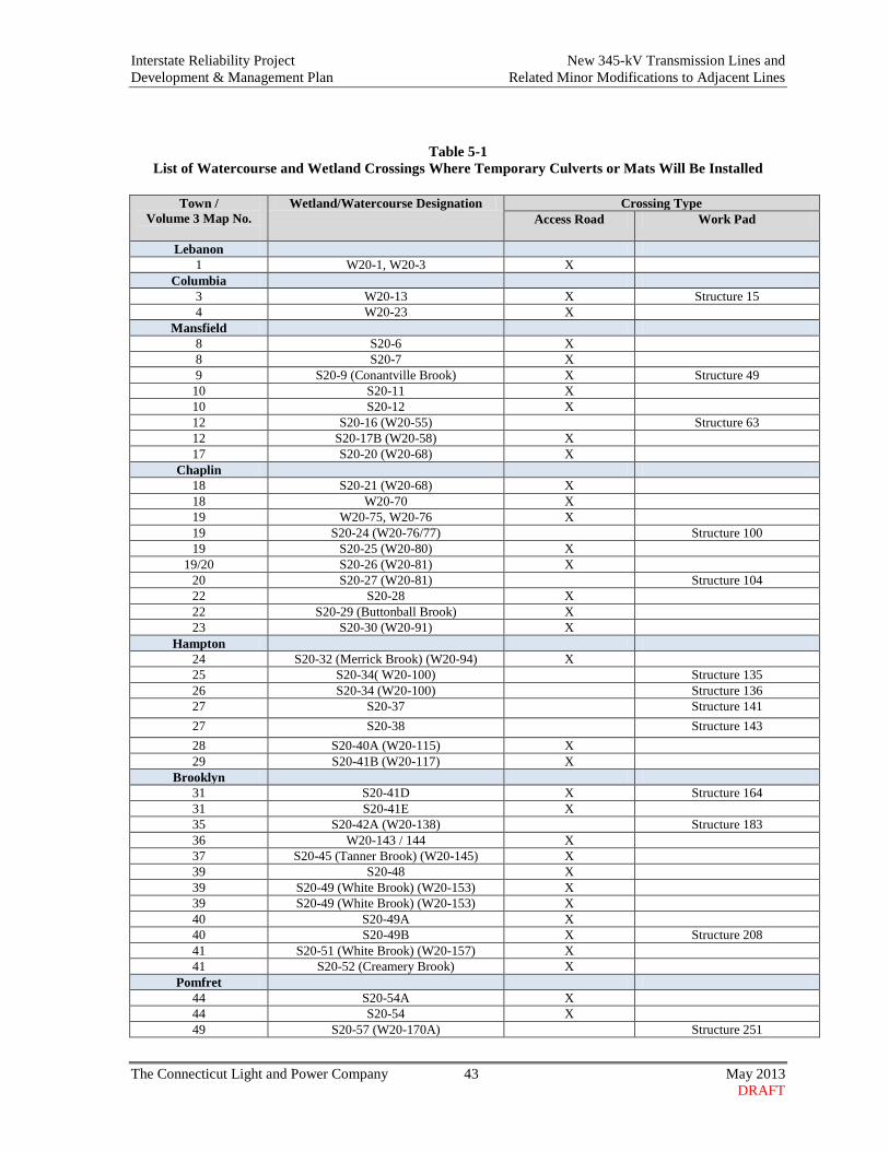
Interstate Reliability Project New 345-kV Transmission Lines and Development & Management Plan Related Minor Modifications to Adjacent Lines
The Connecticut Light and Power Company 43 May 2013 DRAFT
Table 5-1 List of Watercourse and Wetland Crossings Where Temporary Culverts or Mats Will Be Installed
Town /
Volume 3 Map No.
Wetland/Watercourse Designation Crossing Type Access Road Work Pad
Lebanon 1 W20-1, W20-3 X
Columbia 3 W20-13 X Structure 15 4 W20-23 X
Mansfield 8 S20-6 X 8 S20-7 X 9 S20-9 (Conantville Brook) X Structure 49
10 S20-11 X 10 S20-12 X 12 S20-16 (W20-55) Structure 63 12 S20-17B (W20-58) X 17 S20-20 (W20-68) X
Chaplin 18 S20-21 (W20-68) X 18 W20-70 X 19 W20-75, W20-76 X 19 S20-24 (W20-76/77) Structure 100 19 S20-25 (W20-80) X
19/20 S20-26 (W20-81) X 20 S20-27 (W20-81) Structure 104 22 S20-28 X 22 S20-29 (Buttonball Brook) X 23 S20-30 (W20-91) X
Hampton 24 S20-32 (Merrick Brook) (W20-94) X 25 S20-34( W20-100) Structure 135 26 S20-34 (W20-100) Structure 136 27 S20-37 Structure 141 27 S20-38 Structure 143 28 S20-40A (W20-115) X 29 S20-41B (W20-117) X
Brooklyn 31 S20-41D X Structure 164 31 S20-41E X 35 S20-42A (W20-138) Structure 183 36 W20-143 / 144 X 37 S20-45 (Tanner Brook) (W20-145) X 39 S20-48 X 39 S20-49 (White Brook) (W20-153) X 39 S20-49 (White Brook) (W20-153) X 40 S20-49A X 40 S20-49B X Structure 208 41 S20-51 (White Brook) (W20-157) X 41 S20-52 (Creamery Brook) X
Pomfret 44 S20-54A X 44 S20-54 X 49 S20-57 (W20-170A) Structure 251

Interstate Reliability Project New 345-kV Transmission Lines and Development & Management Plan Related Minor Modifications to Adjacent Lines
The Connecticut Light and Power Company 44 May 2013 DRAFT
Town / Volume 3 Map No.
Wetland/Watercourse Designation Crossing Type Access Road Work Pad
Killingly 50 S20-57A (W20-171) X
Putnam 58 S20-60D (W20-187) Structure 291 59 W20-191 X 59 S20-61A (Lippitts Brook) (W20-193) X 60 W20-194 X 61 S20-62 Structure 311 62 S20-63 (Munson Brook) (W20-198) X 62 W20-199 X
Thompson 64 S20-66 (Teft Brook) (W20-207) X 66 S20-68 (W20-211) X
Table 5-2 Proposed New Permanent Culverts along Access Roads
Stream Number (Town)
Volume 3 Map
Number
Associated Wetland
Vernal Pool To Be
Permanently Impacted
Stream Type
Fisheries Classification
Within FEMA Flood Zone
Watershed Size Above
Culvert (acres)
Access Road Type
S20-8 (Mansfield) 9 W20-43 - P AA/
warm-water No 13.4 Existing
S20-28 (Chaplin) 22 W20-88 - I AA No 48.2 Existing
S20-29 Buttonball
Brook (Chaplin)
22 W20-89 CH-14 (access road) P AA/
cold-water No 28.3 Existing
S20-35 (Hampton) 26 W20-101 HA-5 I A No 23.1 Existing
S20-36 (Hampton) 27 W20-103 - I A No 30.2
New Permanent
W20-203
(Hampton) 27 - - - - No - New Permanent
S20-41A Humes Brook
(Hampton)
29 W20-118 - I A No 69.8 New Permanent

Interstate Reliability Project New 345-kV Transmission Lines and Development & Management Plan Related Minor Modifications to Adjacent Lines
The Connecticut Light and Power Company 45 May 2013 DRAFT
New construction access roads through wetlands. New temporary construction access roads across wetlands will be established using timber mats, gravel overlying geotextile fabric, or equivalent. New permanent access across wetlands will be established using gravel. Such new access roads will also require 16- to 20-foot-wide or more travel widths and will involve a total width of approximately 20 to 25 feet (wider in certain areas to allow for equipment turning radius or passing lanes). In larger wetlands that have a deep organic layer or are prone to extended inundation, the lower portion of the crushed stone access roads may remain in place, if approved by the CT DEEP and USACE, to provide a permanent access road base for future use during line maintenance and ROW management. In such cases, the fill used to construct the access roads would be removed to the approximate pre-construction elevation. The underlying material would provide a firm base for equipment access or for the future placement of temporary timber mats to allow equipment used in line maintenance or ROW management activities to cross these larger wetland systems. All other timber mat or gravel access roads will be removed in their entirety after construction. Permanent access across wetlands will only be as approved in the CT DEEP and USACE Project-specific regulatory approvals. Transmission Line Structures in Wetlands. In general, where a new structure must be located in a wetland, timber mats will be used to create a temporary work pad for construction support. In some wetland areas, however, field conditions (such as thickness of organic soils, depth of water, or sloping terrain, etc.) may require the use of a temporary crushed stone pad to provide a safe working surface. 5.2.3 Flood Zones and Stream Channel Encroachment Lines The new 345-kV transmission lines will span the state-designated Stream Channel Encroachment Lines (SCEL) associated with the Willimantic River, as well as flood zones, as designated by the Federal Emergency Management Agency (FEMA), along this river and various other watercourses in each of the 11 towns along the Project ROWs. The new transmission lines also will span FEMA-designated floodways associated with five watercourses. The Volume 3 maps illustrate the boundaries of the Willimantic River SCEL, as well as FEMA-designated floodways, 100-year floodplains, and 500-year floodplains. Pursuant to CL&P’s agreement with CT DEEP, after CT DEEP issues the SCEL / 401 Water Quality Certification for the Project, but prior to the commencement of construction activities, CL&P will notify the floodplain coordinator in each of the 11 towns, identifying the types of Project activities that will occur within 100-year floodplains in each municipality. No new transmission line structures or new permanent access roads will be located within the Willimantic River SCEL or within any floodways. However, 36 new transmission line structures will be placed within 100-year floodplains associated with 14 waterbodies. Temporary construction work pads and access roads will be located within 100- and 500-year floodplains. Such temporary facilities will be constructed using timber mats or aggregate materials

Interstate Reliability Project New 345-kV Transmission Lines and Development & Management Plan Related Minor Modifications to Adjacent Lines
The Connecticut Light and Power Company 46 May 2013 DRAFT
(rock). Within 100- and 500-year floodplain areas, timber mats will be anchored to avoid or minimize the potential for flotation in the event of a flood. The specific method used for anchoring the construction mats will be selected by CL&P’s construction contractor, after taking into consideration site-specific conditions. Typical options will be to anchor the construction mats with stakes and/or to anchor the mats to each other. After the completion of transmission line installation, temporary access roads and work pads within 100-year floodplains will be removed. Similarly, any existing access roads within FEMA-designated 100-year floodplains that are improved for use during the construction of the transmission lines will be restored to pre-construction conditions after the completion of Project work activities. 5.2.4 Aquifer Protection North of State Route 12 (Killingly Avenue) in the Town of Putnam, the ROW extends across the eastern edge of a Level A Aquifer Protection Area (APA) (No. 112), as mapped by the CT DEEP. Approximately 3.3 acres of the ROW are located within the APA (refer to Volume 3, maps 56 and 57). No new transmission line structures will be placed along the ROW in this area, but three new structures (Nos. 283, 284, and 285) will be located adjacent to the edge of the APA. In addition, new and existing access roads will be required for construction along the ROW in and near the APA (refer to Volume 3, maps 56 and 57). To avoid or minimize the potential for spills related to construction activities in the APA, construction activities will be performed in accordance with Condition 8 of the CT DEEP 401 Water Quality Certification and SCEL permit (refer to Volume 2, Attachment G). Vehicle maintenance, storage, and refueling will be performed a minimum distance of 100 feet from the APA, to the extent practicable. If necessary to complete emergency maintenance, or store and/or refuel less mobile equipment (e.g., drill rigs or cranes) in or within 100 feet of the APA, the construction contractor will be required to use appropriate secondary containment devices. In addition, each construction vehicle will be required to have a spill kit containing materials with the capacity to absorb up to 5 gallons of liquid for use during emergencies. Storage of hazardous materials within 100 feet of the APA also will be minimized to the extent practicable. If circumstances do not allow this, the contractor will be required to deploy secondary containment devices. 5.2.5 Drainage Areas where existing surface drainage patterns could pose concerns during construction were identified based on the results during field constructability reviews of the Project ROWs. These areas are noted on the Volume 3 maps. CL&P will require its construction contractor to assess such areas and implement BMPs as appropriate to site-specific situations, in order to avoid or minimize erosion and sedimentation and to maintain hydrology and drainage patterns.

Interstate Reliability Project New 345-kV Transmission Lines and Development & Management Plan Related Minor Modifications to Adjacent Lines
The Connecticut Light and Power Company 47 May 2013 DRAFT
5.3 VERNAL POOLS AND AMPHIBIAN BREEDING HABITAT No new transmission line structures will be located in vernal pools, but improvements to four existing on-ROW access roads will affect vernal pools. Vegetation removal also will be required in or near vernal pools. The measures that CL&P will implement to avoid or minimize impacts to the 88 vernal pools identified along the Project ROWs are described in the Project-Wide Avoidance and Minimization Protocol for Vernal Pools (Appendix E). The Project ROWs include 29 amphibian breeding habitats (refer to the Volume 3 maps). CL&P has designed the Project facilities to avoid or minimize work in these habitats where possible. However, some of these habitats encompass large wetland complexes that extend linearly along the ROWs and within which construction activities will be required. Table 5-3 summarizes the mapped amphibian breeding habitats in which Project construction activities will occur. In such areas, CL&P will implement typical wetland mitigation measures (refer to Appendix B). Both vernal pools and amphibian breeding habitats are identified on the Volume 3 maps.

Interstate Reliability Project New 345-kV Transmission Lines and Development & Management Plan Related Minor Modifications to Adjacent Lines
The Connecticut Light and Power Company 48 March 2013 DRAFT
Table 5-3: Summary of Project Facilities in Amphibian Breeding Habitats
Town and Volume 3 Map
Number
Wetland Number
Amphibian Breeding Habitat (ABH) Number
Existing Conditions (Facilities in ABH) Project Facilities in ABH Structures or Guy
Anchors Access Roads Temporary
Work Pad Permanent Structures or
Guy Anchors Access Roads
Chaplin 17 W20-68 CH-1-ABH Yes 19 W20-77 CH-2-ABH Yes (9099 / 9100) Yes Yes
19/20 W20-81 CH-3-ABH Yes Yes Yes Yes 22 W20-88 CH-5-ABH Yes Yes 22 W20-89 CH-6-ABH Yes Yes 23 W20-91 CH-7-ABH Yes (9119) Yes Yes
Hampton 26 W20-100 HA-1-ABH Yes Yes Yes 26 W20-100 HA-2-ABH Yes 28 W20-112 HA-3-ABH Yes 29 W20-116 HA-4-ABH Yes Yes 29 W20-117 HA-5-ABH Yes (9151, 9152) Yes Yes Yes
Brooklyn 30/31 W20-120 BR-1-ABH Yes Yes
31 W20-122 BR-2-ABH Yes Yes 31/32 W20-122 BR-3-ABH Yes Yes
39A/40 W20-153 BR-5-ABH Yes Putnam
59 W20-191 PU-3-ABH Yes Yes Yes Thompson
63/64 W20-203 TH-1-ABH Yes Yes Yes
Note: The Volume 3 maps identify the locations of mapped amphibian breeding habitats that are within the Project ROWs, but not directly affected by Project facilities.

Interstate Reliability Project New 345-kV Transmission Lines and Development & Management Plan Related Minor Modifications to Adjacent Lines
The Connecticut Light and Power Company 49 May 2013 DRAFT
5.4 PROTECTION MEASURES FOR STATE-LISTED SPECIES 5.4.1 Overview As part of the planning for the Project, CL&P consulted with the CT DEEP, Natural Diversity Database (NDDB)6 to:
• Determine whether any species listed by the state government as threatened, endangered, or species of special concern are known to occur along or in the vicinity of the Project ROWs, as identified by NDDB records;
• Verify the need for field surveys to provide more specific information regarding the species that
could potentially occur along portions of the ROWs;
• Present the results of field surveys; and
• Identify measures to protect or otherwise avoid or mitigate impacts to those species found to occur in the Project area.
At the recommendation of the NDDB, during 2008-2011, CL&P commissioned field surveys to determine if certain state-listed species occur along the Project ROWs. Based on the results of these surveys and further consultations with CT DEEP, on December 20, 2012, CL&P prepared a State-Listed Species Technical Memorandum (Technical Memorandum) that summarized the state-listed species consultation process and described proposed impact avoidance and minimization measures for state-listed species that could be affected by the Project. On February 21, 2013, CL&P revised and re-issued a Technical Memorandum, incorporating the results of NDDB’s review. The revised Technical Memorandum reflects CL&P’s and the NDDB’s agreement concerning the measures to be implemented to avoid or minimize impacts during Project construction and subsequent long-term ROW management to protect the identified state-listed species and their habitats. As such, the Technical Memorandum supersedes any mitigation measures that CL&P proposed in its Application to the Council. This section summarizes the protection, mitigation, and management measures included in the Technical Memorandum.7 CL&P will implement these measures, as appropriate, during the construction of the Project. The protection, mitigation, and management measures are consistent with the Council’s approval of the Project8 and with Special Condition 3 of the CT DEEP’s Stream Channel Encroachment Line Permit and Section 401 Water Quality Certification for the Project. 6 CL&P also consulted with the U.S. Fish and Wildlife Service regarding federal-listed species. No such species are found in the Project area. 7 The Technical Memorandum includes confidential mapping regarding state-listed species locations and thus is not provided for public review. 8 State-listed species impact mitigation and protection measures are discussed in the Council’s Opinion (Docket 424), p. 10. In its Application to the Council (Volume 1, pp. 6-49 to 6-51), CL&P anticipated that mitigation and avoidance measures may be required for the wood turtle (Glyptemys insulpta), which was identified in NDDB

Interstate Reliability Project New 345-kV Transmission Lines and Development & Management Plan Related Minor Modifications to Adjacent Lines
The Connecticut Light and Power Company 50 May 2013 DRAFT
The general locations of state-listed species habitat to be protected during construction are identified on the Volume 3 maps. CL&P’s construction contractor will be required either to avoid such areas or to implement special procedures for minimizing adverse effects to listed species during construction activities. In addition, implementation of measures to avoid or otherwise protect state-listed species will be emphasized in the Project environmental training, which CL&P will require construction personnel to attend prior to performing work on the ROWs. 5.4.2 Eastern Ribbon Snake (Thamnophis sauritus) Species Designation: Species of Special Concern General Habitat: Wet sedge meadows and the upland edges of ponds and streams ROW Areas of Habitat Concern:
• Town of Chaplin, east of Chewink Road, between existing Structures 9111 and 9113. (Volume 3, map 21)
• Town of Hampton, west of Pudding Hill Road, existing Structure 9133 to Structure 9136. (Volume 3, map 26)
• Town of Killingly, from existing Structure 9246, northeast to Lake Road. (Volume 3, map 49) • Town of Putnam, from existing Structure 9291 northeast to the northeastern end of wetland W20-
191. (Volume 3, map 59) General Protective Measures:
A contractor awareness program will be developed and implemented prior to construction. The main objectives of this program will be to educate the contractors’ field personnel regarding: a. The identification of the Eastern ribbon snake and its habitat. The contractors’ field personnel
will be shown photographs of Eastern ribbon snakes, and will be provided with information about the species’ preferred habitat so that they will know where it would most likely be found.
b. The proper procedures to follow should an Eastern ribbon snake be observed in an active work space.
Site-Specific Impact Avoidance and Minimization Measures:
During the Eastern ribbon snake’s active period (April 1 through October 31), all active construction work spaces within or near the portions of the ROW listed above will be investigated daily prior to the commencement of construction activities. Any Eastern ribbon snakes found within the ROW shall only be removed from active construction workspaces by one of the Project’s Environmental Inspectors, who is designated and qualified to do so. If it is necessary to move a snake from an active work space, it will be moved to a safe location in the general vicinity of the ROW.
records as potentially occurring in the vicinity of the Project ROW near the Quinebaug River in the Town of Pomfret. The Council’s Opinion also anticipated that CT DEEP could require CL&P to implement measures to avoid or mitigate potential impacts to the wood turtle. However, CL&P’s subsequent consultations with NDDB revealed that no special avoidance or mitigation measures would be required for the wood turtle.
Interstate Reliability Project New 345-kV Transmission Lines and Development & Management Plan Related Minor Modifications to Adjacent Lines
The Connecticut Light and Power Company 51 May 2013 DRAFT
5.4.3 Eastern Hognose Snake (Heterodon platirhinos) Species Designation: Species of Special Concern General Habitat: Woodlands with sandy soil, fields, and farmland ROW Areas of Habitat Concern:
• Town of Mansfield, east of Storrs Road, from existing Structure 9072 northeast to existing Structure 9080. (Volume 3, maps 14 and 15)
General Protective Measures:
A contractor awareness program will be developed and implemented prior to construction. The main objectives of this program will be to educate the contractors’ field personnel regarding:
a. The identification of the Eastern hognose snake and its habitat. The contractors’ field personnel will be shown photographs of Eastern hognose snakes, and will be provided with information about the species’ preferred habitat so that they will know where it would most likely be found.
b. The proper procedures to follow should an Eastern hognose snake be observed in an active
work space. Site-Specific Impact Avoidance and Minimization Measures:
During the Eastern hognose snake’s active period (April 1 through October 31), all active construction work spaces within or near the portion of the ROW listed above will be investigated daily prior to the commencement of construction activities. Any Eastern hognose snakes found within the ROW shall only be removed from active construction work spaces by one of the Project’s Environmental Inspectors, who is designated and qualified to do so. If it is necessary to move a snake from an active work space, it will be moved to a safe location in the general vicinity of the ROW.
5.4.4 Aquatic Snail (Gyraulus circumstriatus) Species Designation: Species of Special Concern General Habitat: Inland bodies of fresh water (generally less than 3 meters deep) ROW Areas of Habitat Concern:
• Town of Mansfield, from existing Structure 9085 northeast to existing Structure 9086. (Volume 3, map16; Mansfield Hollow Lake: Project construction will not directly affect the lake.)
Site-Specific Impact Avoidance and Minimization Measures:
a. To minimize the potential for sediments resulting from construction activities reaching Mansfield Hollow Lake, CL&P will explain to the contractors that strict adherence to the Project’s erosion and sedimentation control requirements (refer to the BMPs in Volume 2, Attachment E) is a standard expectation. During construction activities, BMPs (such as silt

Interstate Reliability Project New 345-kV Transmission Lines and Development & Management Plan Related Minor Modifications to Adjacent Lines
The Connecticut Light and Power Company 52 May 2013 DRAFT
fence, staked bales, filter socks, other temporary stabilization), and re-vegetation of disturbed areas will be used. All erosion and sedimentation controls will be removed upon final stabilization of the site.
b. A minimum 25-foot buffer along the shoreline of Mansfield Hollow Lake will be established
and maintained. Within this buffer, all tree and shrub species capable of growing to mature heights greater than 30 feet will be removed in order to comply with federally mandated clearance requirements between the overhead transmission line conductors and any vegetation. However, all other vegetation removal from within the buffer will be minimized to the extent practicable.
5.4.5 Moustached Clubtail Dragonfly (Gomphus adelphus) Species Designation: State Threatened General Habitat: Cold-water rivers with gravelly or rocky bottoms ROW Areas of Habitat Concern:
• Town of Chaplin, from existing structure 9095 east to existing structure 9096. (Volume 3, map 18; Natchaug River: Project construction activities will not directly impact the river.)
Site-Specific Impact Avoidance and Minimization Measures:
a. To minimize the potential for sediments resulting from construction activities reaching the Natchaug River, CL&P will communicate to the contractors that strict adherence to the Project’s erosion and sedimentation control requirements (refer to the BMPs in Volume 2, Attachment E) is a standard expectation. During construction activities, BMPs, such as silt fence, staked bales, filter socks, and re-vegetation of disturbed areas will be utilized. All erosion and sedimentation controls will be removed upon final stabilization of the site.
b. A minimum 25-foot buffer along the banks of the Natchaug River will be established and
maintained. Within this buffer, all tree and shrub species capable of growing to mature heights greater than 30 feet will be removed in order to comply with federally mandated clearance requirements between the overhead transmission line conductors and any vegetation. However, all other vegetation removal from within the buffer will be minimized to the extent practicable.
5.4.6 Brook Floater (Alasmidonta varicosa) and Eastern Pearlshell Mussel (Margaritifera
margaritifera) Species Designation: Brook floater = State Threatened; Eastern pearlshell mussel = Species of Special
Concern General Habitat: Natchaug River ROW Areas of Habitat Concern:
• Town of Chaplin, from existing Structure 9095 east to existing Structure 9096.

Interstate Reliability Project New 345-kV Transmission Lines and Development & Management Plan Related Minor Modifications to Adjacent Lines
The Connecticut Light and Power Company 53 May 2013 DRAFT
(Volume 3, map 18; Natchaug River: Project construction activities will not directly impact the river.)
Site-Specific Impact Avoidance and Minimization Measures:
a. To minimize the potential for sediments resulting from construction activities reaching the Natchaug River, CL&P will communicate to the contractors that strict adherence to the Project’s erosion and sedimentation control requirements (refer to the BMPs in Volume 2, Attachment E) is a standard expectation. During construction activities, BMPs, such as silt fence, staked bales, filter socks, and re-vegetation of disturbed areas will be utilized. All erosion and sedimentation controls will be removed upon final stabilization of the site.
b. A minimum 25-foot buffer along the banks of the Natchaug River will be established and
maintained. Within this buffer, all tree and shrub species capable of growing to mature heights greater than 30 feet will be removed in order to comply with federally mandated clearance requirements between the overhead transmission line conductors and any vegetation. However, all other vegetation removal from within the buffer will be minimized to the extent practicable.
5.4.7 Moths and Butterflies (Lepidoptera) Summary of Surveys: In response to the CT DEEP’s recommendation that surveys of the Project ROWs be performed for Lepidoptera (moths and butterflies), CL&P retained the University of Connecticut’s Center for Conservation Biology (CCB). The purpose of the investigations was to identify occurrences of State-listed Lepidoptera and to survey of some of the host plant community types known to be associated with the State-listed species.9 Species Name and Designation: During the surveys, 10 state-listed Lepidoptera species were found along the ROWs:
• Apamea burgessi (Burgess Cutworm) - Special Concern • Callophrys irus (Frosted Elfin) - Threatened • Erynnis brizo (Sleepy Duskywing) - Threatened • Erynnis persius (Persius Duskywing) - Endangered • Euchlaena madusaria (Scrub Euchlaena) - Special Concern • Eucoptocnemis fimbriaris (no common name) - Special Concern • Hemiaris gracilis (Slender Clearwing) - Threatened • Hemileuca maia (Buck Moth) - Endangered • Metarranthis apiciaria (Barrens Metarranthis) - Endangered • Sympistis perscripta (=Lepipolys perscripta) (Scribbled Sallow) - Special Concern
9 The CCB’s Final Report Insect Survey for the Interstate Reliability Project (April 18, 2011; Final Insect Report) is included in Volume 4 of CL&P’s Application to the Council.
Interstate Reliability Project New 345-kV Transmission Lines and Development & Management Plan Related Minor Modifications to Adjacent Lines
The Connecticut Light and Power Company 54 May 2013 DRAFT
General Habitat: The CCB distinguished and mapped five plant communities and host plant species that particularly support these populations:
• Bluestem grassland (Schizachyrium scoparium and/or Andropogon virginicus) • Low bush blueberry (Vaccinium angustifolium and/or V. pallidum) • Scrub oak (Quercus ilicifolia) • Wild indigo (Baptisia tinctoria) • Bluestem-scrub oak-low bush blueberry mosaic.
Specific Areas of Habitat Concern: At two locations, site-specific mitigation measures will be implemented during construction:
a. From existing Structure 9258 (new Structure 260) west of the Quinebaug River in Putnam to existing Structure 9273 (new Structure 277) northeast of Park Road in Putnam (Volume 3, maps 52 to 55); and
b. From existing Structure 9323 (new Structure 330) northeast of Elmwood Hill Road in Thompson
to the Connecticut/Rhode Island border (Volume 3, map 66). In addition, construction activities will be minimized to the extent practicable along portions of the ROWs where the CCB identified host plant communities, as illustrated on the Volume 3 maps. Impact Minimization and Management Measures: The CCB concluded that the Project will have a long-term beneficial impact on the moth and butterfly species that use scrub-shrub habitat, which will increase as a result of the construction and management of the new 345-kV transmission lines. Further, CL&P will implement both short- and long-term measures to avoid and minimize impacts to mapped host plants and host plant community associations during construction and to promote host plant habitat during ROW management. Short-term (Construction Phase) Measures Project construction activities, including vegetation clearing and the development of access roads and work pads, will temporarily affect the mapped host plants and plant community associations. In the “Specific Areas of Habitat Concern” identified above, to the extent practicable, CL&P will minimize temporary, short-term impacts to the host plants and plant community associations by minimizing mowing and ground disturbance outside of the areas required to safely complete the necessary vegetation removal and construction activities. During pre-construction environmental training, CL&P will inform construction contractor personnel of the approximate boundaries of the CCB-mapped host plant and plant community associations. The intent will be to increase general awareness about the locations of the mapped host plant and plant community

Interstate Reliability Project New 345-kV Transmission Lines and Development & Management Plan Related Minor Modifications to Adjacent Lines
The Connecticut Light and Power Company 55 May 2013 DRAFT
associations and to emphasize that impacts to these areas will be minimized to the extent practicable. With the exception of scrub oak, contractors will not be trained to identify individual plant species. Prior to the commencement of construction activities in the “Specific Areas of Habitat Concern”, the boundaries of the host plant and plant community associations identified by the CCB will be flagged by CL&P’s Environmental Inspectors. Future Management Measures As recommended by the CCB, CL&P modified its Integrated Vegetation Management (IVM) program to include scrub oak as a compatible ROW species that will not be removed during future ROW management. Other Lepidoptera host plant species (e.g., lowbush blueberry, bluestem) are shrub or grassland species that CL&P already considers compatible with overhead transmission line ROWs. Therefore, preservation of some of the host plant species is already occurring along CL&P’s ROWs in general. The CCB also recommended the management of invasive species as a key measure for conserving and promoting host plant populations. CL&P’s IVM program already includes provisions for the control of certain invasive shrubs. The removal of these and other woody, invasive shrubs during routine ROW vegetation management will continue to assist in promoting the growth of native species, including the host plants identified by the CCB. 5.5 AIR QUALITY PROTECTION (MINIMIZATION OF DUST AND VEHICLE
IDLING PROTOCOL) Dust Suppression and Anti-Tracking Pads To minimize short-term adverse effects to air quality during construction, access roads and staging areas will be graveled and may be watered, as necessary, to suppress fugitive dust emissions. Additionally, crushed stone aprons will be installed at all gravel or dirt access road entrances to public roadways, with the objective of minimizing tracking of soil onto the roadway. Paved roads at the intersection with ROW access roads will be periodically swept, as necessary to remove excess dirt tracked onto the pavement from the ROW. Construction Equipment: Idling vs. Warm-up During Cold Weather Vehicle emissions will be limited by requiring contractors to properly maintain construction equipment and vehicles, and by minimizing the idling time of diesel construction equipment in accordance with regulatory standards. Idling requirements are as follows:
Interstate Reliability Project New 345-kV Transmission Lines and Development & Management Plan Related Minor Modifications to Adjacent Lines
The Connecticut Light and Power Company 56 May 2013 DRAFT
Unnecessary construction equipment and vehicle idling expends fuel, increases costs, and causes air pollution. For the Project, pursuant to Connecticut requirements (RCSA 22a-174-18), the allowable idling time for vehicles of all kinds, including diesel construction equipment, is 3 minutes. However, under winter work conditions (when the ambient temperature is below 20 degrees Fahrenheit) the following apply:
• Construction equipment may require longer periods to warm up after overnight shut down or other extended periods of inactivity. Such “warm up” periods, as required to bring the equipment up to a safe operating temperature (as defined by the equipment manufacturer), are exempt from the idling time limit. However, most diesel engines take 3 minutes or less to warm up (contractors should consult the engine manufacturer’s recommendations).
• Construction equipment may have to idle for longer periods to operate defrosting or heating
equipment to ensure the safety or health of the driver. Note: “Idling” is defined as the period when mobile construction equipment is not in motion or is not otherwise actively performing its designated function. Thus, “idling” does not apply to the use of certain types of mobile construction equipment (e.g., cranes, cement mixers) that may be stationary, but is actively operating, at a work site. 5.6 PROCEDURES FOR CROSSING PUBLIC TRAILS, PRESERVED /
PROTECTED OPEN SPACE, AND RECREATIONAL AREAS The new 345-kV transmission lines will cross various public trails and recreational areas, including:
• Mansfield Hollow State Park, Mansfield Hollow Lake, and portions of the Mansfield Hollow WMA;
• The Nipmuck Trail (a Connecticut Forest and Park Association [CFPA]) public trail (two
crossings)
• Two state-designated trails managed by the CT DEEP (i.e., the Airline State Park Trail [crossed twice] and Hop River Trail); and
• The Tracey Road Trail, an urban walking/biking path designated by both CT DEEP and
ConnDOT. In addition, the transmission line ROWs also traverse state forest land, private hunting/conservation lands, and State Route 169, a National Scenic Byway. These and other designated open space and public use areas traversed by the 345-kV transmission line ROWs are listed in Table 5-4 and illustrated on the Volume 3 maps.

Interstate Reliability Project New 345-kV Transmission Lines and Development & Management Plan Related Minor Modifications to Adjacent Lines
The Connecticut Light and Power Company 57 May 2013 DRAFT
Table 5-4 Public Trails, Recreational Areas, and Designated Open Space Crossed by or Abutting the 345-kV
Transmission Lines* Location (Town)
Volume 3 Map
Number
Line List (Parcel) No.
Description (Owner or Stakeholder)
Lebanon 1-2 30005 Airline State Park Trail (Southern Section) (CT DEEP) Coventry 5 30055 Hop River State Park Trail (CT DEEP) 6-7 30072, 30075 Town Open Space (Flanders River Road) Mansfield 8 30096, 30100 Town Open Space (Highland Road) 12 30117 Nipmuck Trail (CFPA), West Branch 15-17 30163 Mansfield Hollow State Park, Mansfield Hollow Lake, & WMA
(CT DEEP and USACE) 15 30163 Mansfield Hollow Dam Levee Trail (within Mansfield Hollow
State Park) (CT DEEP and USACE) 15-16 30163 The Red Trail (within Mansfield Hollow State Park) (CT DEEP
and USACE) 17 30168 Nipmuck Trail (CFPA), East Branch (on CL&P property) Chaplin 18-19 30186, 30188,
30189 Mansfield Hollow WMA / Natchaug River (CT DEEP and USACE)
22 30220 Natchaug State Forest, Air Line State Park Trail (North Section) [abuts ROW] (CT DEEP)
Hampton 24 30240 Airline State Park Trail (Northern Section), Natchaug State Forest Brooklyn 36-37 30318 Milo Appley Conservation Showcase and Trails - Eastern CT
Conservation District 41 30342 Wolf Den Land Trust White Brook Wildlife Sanctuary - Eastern
CT Conservation District 43-44 30368 Quinebaug River Trail (adjacent to ROW) (NU, trails managed by
Town) Pomfret 47 30380 Town Open Space (near Quinebaug River) 47 30381 Town Canoe / Kayak Boat Launch (adjacent to ROW at State
Route 101) Putnam 54 31012 Tracey Road Trail (Town, CT DEEP, ConnDOT) 63 31092 Lower Pond Reserve (Wyndham Land Trust, Inc.) Thompson 63 31096 Lower Pond Reserve (Wyndham Land Trust, Inc. ) 64-65 31113 Tamler Preserve – Wyndham Land Trust (includes trail, not
crossed) * Notes: (1) No trails or public recreational lands traversed or abutting the ROW in the towns of Columbia or Killingly. (2) Public access is not available or encouraged to some land trust and open space parcels.

Interstate Reliability Project New 345-kV Transmission Lines and Development & Management Plan Related Minor Modifications to Adjacent Lines
The Connecticut Light and Power Company 58 May 2013 DRAFT
5.6.1 Consultations and Site-Specific Plans CL&P has or will consult with the owners or managers of each of the recreational and open space properties to discuss the Project, review the types of construction activities that will be performed on each property, and solicit input regarding the appropriate methods (if any) to be used during construction to minimize disruptions to the public while maintaining public safety. These consultations generally will address the following topics, as applicable to each property:
• Use and placement of construction warning signs • Bike and pedestrian offset gates • Public safety (flagmen) • Temporary trail re-routing or closure during certain construction activities • Trail and/or pavement protection from heavy construction equipment • Construction schedule • Schedule constraints, if any, for construction activities due to peak recreational use periods or
site-specific activities (e.g., hunting season in the WMA) • Regular correspondence and updates, including the use of the Project website to provide
construction status and schedule information • Restoration of areas affected by construction
Based on the consultations, CL&P will develop site-specific mitigation plans, as appropriate, for use during construction across the publicly-accessible recreational areas. Some of the open space parcels identified in Table 5-4 are not currently accessible to the public; as a result, site-specific mitigation plans are not expected to be required in such locations. 5.6.2 Mansfield Hollow Area Along the 36.8-mile Project route in Connecticut, the only areas where the new 345-kV transmission lines cannot be effectively located within CL&P’s existing easements are along two ROW segments through federally-owned lands, totaling approximately 1.4 miles, where CL&P’s existing ROW is 150 feet wide:
• Segment 1: An approximately 0.9-mile segment of CL&P’s existing transmission line ROW traverses Mansfield Hollow State Park, including an approximately 600-foot span of Mansfield Hollow Lake, as well as portions of the WMA (Town of Mansfield, Tolland County); and
• Segment 2: CL&P’s existing transmission line ROW traverses a second portion of the WMA for
approximately 0.5 mile across and in the vicinity of the Natchaug River (Town of Chaplin, Windham County). (Refer to Figure 5-1, below)
Within the Mansfield Hollow area, the ROW traverses the State Park, WMA, and several public-use recreational hiking trails, as well as Mansfield Hollow Lake and the Natchaug River (refer to Table 5-4).

Interstate Reliability Project New 345-kV Transmission Lines and Development & Management Plan Related Minor Modifications to Adjacent Lines
The Connecticut Light and Power Company 59 May 2013 DRAFT
Figure 5-1: Location of the Mansfield Hollow Area, Segments 1 and 2 To accommodate a new 345-kV transmission line adjacent to the existing 330 Line across the Mansfield Hollow area segments (while maintaining clearances from conductors and vegetation and avoiding the need for electrical outages), CL&P requested and will receive from the USACE a conveyance of expanded easement rights, totaling approximately 5 acres. Pursuant to this conveyance, the existing ROW will be expanded by 25 feet to the north through Segment 1 and by 35 feet to the north through Segment 2, thereby allowing the construction of the new 345-kV transmission line, on steel monopoles with vertically arranged conductors, north of and adjacent to the existing 345-kV line. The vertical configuration of the new transmission line in relation to the expanded ROW through Segments 1 and 2 is depicted on the Volume 3 cross-sections, XS-3 and XS-5, respectively. The Volume 3 maps (32-35 for Segment 1 and 38-40 for Segment 2) depict environmental features in relation to the construction areas (access roads, work pads at structure sites, for conductor pulling, and at guard structure sites) that will be required to install the new 345-kV transmission line in the Mansfield Hollow area. Consultations Prior to and During Construction CL&P will coordinate with the USACE, CT DEEP, the CFPA, and the towns of Mansfield and Chaplin to develop appropriate mitigation measures for use during the construction period within the state park and WMA. These measures will be designed to provide for the safety of the public in general and of hikers

Interstate Reliability Project New 345-kV Transmission Lines and Development & Management Plan Related Minor Modifications to Adjacent Lines
The Connecticut Light and Power Company 60 May 2013 DRAFT
using the trails during the construction period and to minimize potential effects on the recreational users of these resources. Construction activities at and near these locations will be confined to the approved utility easement and access roads. Mitigation measures expected to be used to inform and protect the public during construction in the state park and WMA include the placement of construction warning signs along Bassetts Bridge Road near the ROW, signs along the hiking trails, hiking trail detours, and use of fencing (e.g., temporary orange “snow” fencing or equivalent) as necessary around work sites. CL&P also will provide construction updates, identifying construction locations and schedules, on its Project website. The information also will be provided to the agencies, the towns of Mansfield and Chaplin, and the CFPA for inclusion on their websites, if desired. Construction Schedule Construction activities in the Mansfield Hollow area will not commence on the expanded
ROW until the USACE issues the Project’s Section 404 permit and the conveyance of the expanded easement rights.
CL&P will consult with the CT DEEP and the USACE to identify possible construction
scheduling to minimize impacts to recreational uses and to discuss ROW restoration techniques.
Primary construction activities in the Mansfield Hollow area include vegetation removal, structure installation, and conductor and shield wire stringing. Upon completion of these activities, ROW restoration and revegetation will occur. To the extent practicable based on the timing of the receipt of regulatory approvals, CL&P will endeavor to remove forested vegetation along the ROW on federal properties between August 1 and April 1, outside the typical bird nesting season. Construction Procedures To construct the new transmission line within the Mansfield Hollow area, CL&P will adhere to the standard construction procedures identified in this D&M Plan, the procedures described in this section, and any additional requirements that may be included in the Project’s Section 404 permit from the USACE or in the final expanded easement agreement between the USACE and CL&P. CL&P will coordinate with the USACE’s Mansfield Hollow Project Manager and the CT DEEP regarding the disposition of vegetation cleared from the ROW. As illustrated on the Volume 3 maps, CL&P will confine all work pads, access roads, and other activities associated with the construction of the new 345-kV transmission line in the Mansfield Hollow area to the CL&P ROW, except for the following:
• At the Bassetts Bridge Road crossing in Mansfield Hollow State Park, the road grade is higher than the ROW. To allow construction equipment to more easily access the ROW from Bassetts
Interstate Reliability Project New 345-kV Transmission Lines and Development & Management Plan Related Minor Modifications to Adjacent Lines
The Connecticut Light and Power Company 61 May 2013 DRAFT
Bridge Road, CL&P will request approval from the USACE for the development and use of temporary access roads on either side of Bassetts Bridge Road.
• During construction, any trees located outside the existing and expanded easement that pose a
danger or hazard to the integrity of the new transmission line will be removed in accordance with mandatory safety standards for overhead transmission line operation. Danger or hazard tree removal, if required, will be coordinated with the USACE’s Mansfield Hollow Project Manager.
To construct the new transmission line in the Mansfield Hollow area, vegetation will be removed along the northern portions of the ROW/expanded ROW as illustrated on the Volume 3 maps and summarized as follows:
− Along Segment 1, woody vegetation will be removed along a 50-foot-wide area (encompassing both a 25-foot-wide portion of the existing 150-foot-wide ROW that is not presently managed and the 25-foot-wide expanded easement area).
− Along Segment 2, woody vegetation will be removed along a 40-foot-wide area (including a
5-foot-wide portion of the existing ROW that is not presently managed and the 35-foot-wide expanded easement area).
(Notes: 1. Scrub-shrub vegetation along the ROW on the slopes adjacent to Mansfield Hollow Lake and abutting the Natchaug River will not have to be removed because no new structures will be installed in these areas. Instead, in these areas, tree removal or trimming will be performed as required to conform to conductor separation specifications in overhead transmission line standards. 2. Existing woody vegetation within the southern portion of the existing ROW (i.e., the un-managed portions of the existing ROW adjacent to and south of the existing 330 Line), will not be cleared as part of the Project.
In select locations, access roads will be wider to accommodate the turning radii of the large equipment used in the construction of the transmission line facilities. In addition, where access roads must extend down slopes, additional grading will be required to create a safe travel surface for construction equipment. In such instances, the travel-way width of the access roads will be approximately 30 feet wide. ROW Restoration Temporary access roads, work pads, and all other construction materials will be removed. In Segment 2 (Chaplin), the two temporary culverts installed along access roads across wetlands also will be removed. Disturbed upland areas will be re-graded to approximate pre-construction elevations and then re-seeded and stabilized as necessary with mulch. Wetland areas will be re-seeded and stabilized with a native seed mix and then allowed to revegetate naturally (mulch will not be used). Construction debris will be hauled off the ROW for disposal. No piles of debris will be left on the ROW. Vegetative materials cut along the ROW and not otherwise provided to the USACE or CT DEEP for productive use may be piled, scattered, or chipped on the ROW, depending on site-specific environmental

Interstate Reliability Project New 345-kV Transmission Lines and Development & Management Plan Related Minor Modifications to Adjacent Lines
The Connecticut Light and Power Company 62 May 2013 DRAFT
features. No wood piles for wildlife habitat will be created without the prior approval of the USACE Mansfield Hollow Project Manager. To restore the portions of the open field affected by construction along the ROW near Bassetts Bridge Road in Mansfield (refer to Map 32 in Volume 3), the soil may be de-compacted by disking, if warranted. Temporary erosion and sedimentation controls will be maintained until vegetation is re-established or disturbed areas are otherwise stabilized. Areas of exposed soils on steep slopes may be stabilized with jute netting or pre-made erosion control fabric containing seed, mulch, and fertilizer. No plastic erosion-control netting will be used on federal property. After site stabilization is achieved, all temporary erosion and sedimentation controls that are not biodegradable (e.g., geotextile material, twine, stakes) will be removed from the ROW and disposed of properly. Special Mitigation In accordance with Condition 9 of the CT DEEP’s 401 Water Quality Certification for the Project, concurrent with construction activities near Mansfield Hollow Lake (Segment 1), CL&P will install “tree drops” along both sides of the lake shoreline along the ROW. Such “tree drops”, which will involve submerging felled trees and securing them to the lakeside using either a hinge-cut technique or by direct anchoring, create and enhance in-lake habitats for resident fish populations. CL&P will coordinate with the CT DEEP Inland Fisheries staff (860.295.9523) at least 14 days prior to and during this work. Long-Term ROW Management After the installation of the new 3271 Line, 150 feet of the total new 175-foot-wide ROW along Segment 1 and 180 feet of the 185-foot-wide ROW in Segment 2 will be managed to promote low-maturing vegetative species (e.g., dogwood, blueberry, viburnum, mountain laurel, juniper, spicebush, winterberry). All routine ROW management work will be performed in accordance with CL&P’s Specification for Rights-of-Way Vegetation Management (2011). To mitigate for temporary impacts from construction activities along Segments 1 and 2, site-specific wetland enhancement activities, such as wetland invasive species control and monitoring, will be undertaken along the ROW within the Mansfield Hollow area. Invasive species monitoring and control procedures will be implemented in accordance with CL&P’s agreement with CT DEEP (refer to the Wetland Invasive Species Control Plan in Appendix D).
Interstate Reliability Project New 345-kV Transmission Lines and Development & Management Plan Related Minor Modifications to Adjacent Lines
The Connecticut Light and Power Company 63 May 2013 DRAFT
5.7 HANDLING AND DISPOSITION OF EXCAVATED SOIL, GROUNDWATER,
RECYCLABLE MATERIALS, AND WASTES The construction contractor(s) will be responsible for the proper handling and disposal of all excess soils, groundwater, recyclable materials, and other wastes generated during the construction process. Excess excavated soil and groundwater (if encountered in structure foundation excavations) will be handled and disposed of in accordance with the procedures specified in the Guidance for Soils and Groundwater Management (refer to Volume 2, Attachment C). Recyclable materials will be removed from the ROWs and transported off-site for appropriate re-use or salvage, pursuant to CL&P policies. General waste materials and debris other than soil and groundwater will be collected in receptacles at the work sites or in secured containers, either at designated locations along the ROWs or at contractor staging areas or yards. Containers that are not removed or emptied at the end of the work day will be inspected regularly until removed for off-site disposal at approved, regulated waste disposal sites. In no case will solid or liquid wastes (except for excess soil or groundwater, if appropriate) be buried or otherwise disposed of on the ROWs or at contractor staging areas or yards. 5.8 LIGHTING AND NOISE MITIGATION The 345-kV transmission line construction activities will result in localized and short-term increases in ambient noise levels in the vicinity of work sites. Construction-related noise will occur as a result of the operation of equipment and vehicles, including vegetation removal equipment, jackhammers, drilling rigs and cranes. Helicopters also may be used to install transmission line components. Other noise-generating activities may include blasting and the use of implosive connectors (for conductor installation). At this time, CL&P does not anticipate that blasting will be required or that implosive connectors will be used. Should one of both of these techniques be used, the procedures presented in Section 5.19 will apply to the preparation of appropriate site-specific plans. Because noise attenuates with distance, the effects of construction-generated noise will depend on the noise source location in relation to noise receptors. Temporary noise impacts associated with construction will be minimized because the ROWs extend across relatively remote areas and because noise from construction will be relatively short-term and limited primarily to daylight hours (i.e., between 7 AM and 7 PM) when human sensitivity to sound is lower. In addition, CL&P will require its Contractors to properly maintain and muffle equipment and vehicles to minimize noise emissions.

Interstate Reliability Project New 345-kV Transmission Lines and Development & Management Plan Related Minor Modifications to Adjacent Lines
The Connecticut Light and Power Company 64 May 2013 DRAFT
The 345-kV transmission line construction work will be performed principally during daylight hours. Therefore, temporary lighting is not expected to be required on a routine basis. If needed to accomplish specific tasks that cannot otherwise be suspended, construction lighting will be focused on the targeted work areas and will have only a short-term and localized effect. 5.9 SITE ACCESS, TRAFFIC CONTROL, AND CONSTRUCTION SIGNS During construction, the access to the Project ROWs will be via the public road network. On- and off-ROW access roads will provide direct ingress/egress to construction work sites, as illustrated on the Volume 3 maps. To minimize the potential for traffic issues during construction, CL&P (or CL&P’s construction contractor) will develop access and traffic control plan(s), working with representatives of the affected towns. Such plan(s), which will be implemented by CL&P’s construction contractor, will define traffic-control requirements and identify measures for safe ingress and egress to the ROWs for construction equipment and other vehicles (e.g., at construction work sites along public roads, signs will be erected to indicate the presence of construction work zones and flaggers or police personnel may be used to direct traffic, as needed). The construction contractor will be responsible for posting and maintaining construction warning signs, in accordance with state and local requirements, along public roads in the vicinity of the work areas along the ROWs. Signs will be consistent with the federal Manual of Uniform Traffic Control Devices ([MUTCD], 2009 edition, as revised May 2012, or the latest version)10. Flagmen and other traffic control measures may also be used as necessary. 5.10 CULTURAL RESOURCES 5.10.1 Protection Measures CL&P’s cultural resource consultants have coordinated with the Office of State Archaeology ([OSA] representing the SHPO) and conducted extensive surveys of the transmission line ROWs, resulting in the identification of various archaeological sites and features determined to be of importance. Volume 2, Attachment I includes correspondence from the OSA commenting on CL&P’s surveys for archaeological and historic resources along the transmission line ROWs. To protect the integrity of the cultural resources, the locations of such sites and features are not specifically identified in this D&M Plan. On the Volume 3 maps, the locations of cultural resources, are identified generically. CL&P’s construction contractor will be required either to avoid such areas or to follow special procedures to avoid impacts to cultural resources during construction. , Signs and
10 Connecticut has adopted the federal MUTCDs.
Interstate Reliability Project New 345-kV Transmission Lines and Development & Management Plan Related Minor Modifications to Adjacent Lines
The Connecticut Light and Power Company 65 May 2013 DRAFT
boundary fencing for sensitive cultural and environmental resources also will be installed as needed on a site-specific basis. Sites determined eligible for the National or State Registers of Historic Places (NRHP/SRHP) will be avoided or protected, if possible. At any NRHP/SRHP eligible sites that cannot otherwise be avoided or protected, CL&P will develop mitigation strategies, which may include data recovery sufficient to document significant information which may be lost to adverse Project effects. All avoidance and/or protection measures and mitigation strategies will be developed in consultation with SHPO (OSA) and other consulting parties, as applicable. Further, CL&P will retain a cultural resource monitor, who will be on-site or on-call during construction. 5.10.2 Unanticipated Cultural Resources Discovery Procedures CL&P will require all contractor personnel to attend Project-specific environmental training, a component of which provides procedures for generally identifying and protecting cultural resources. The training will describe the procedures to be followed should unanticipated potential cultural materials be discovered during construction. Specifically, construction personnel will be instructed to stop the task that resulted in the potential discovery and inform CL&P. In addition, CL&P will have a professional archaeological consulting firm on-call and available to respond to potential unanticipated cultural resource discoveries. Construction work at the potential cultural resource discovery site will not resume until authorized by the professional archaeologist and CL&P. 5.11 CONSTRUCTION EQUIPMENT / VEHICLE WASHING AND CLEANING With the exception of cement trucks, no construction equipment or vehicle washing will be allowed on the ROWs. Cement truck wash-out will be allowed only in designated locations, which will be selected to minimize the potential for off-site environmental impacts. All wash-out areas will include measures to control and contain wash-water and to collect the cement wash-off for off-site disposal. Erosion and sedimentation controls deployed at designated wash-out areas will conform to the relevant provisions of the BMP Manual and the CT DEEP’s General Permit for the Discharge of Stormwater and Dewatering Wastewaters Associated with Construction Activities (refer to Volume 2, Attachments E and F). As required pursuant to the Wetland Invasive Species Control Plan (refer to Appendix D), construction vehicles, equipment, and mats also must be cleaned to prevent the transport of invasive wetland species. The cleaning protocol will typically involve the use of shovels, brooms, and/or compressed air to remove visible dirt from construction equipment, vehicles, and mats.
Interstate Reliability Project New 345-kV Transmission Lines and Development & Management Plan Related Minor Modifications to Adjacent Lines
The Connecticut Light and Power Company 66 May 2013 DRAFT
5.12 WATER SOURCES Water may be required for dust suppression or other construction activities. The contractor’s water sources must be pre-approved by CL&P. 5.13 UTILITY CROSSINGS Above-ground utilities and marked underground utilities are identified on the Volume 3 maps. During construction, the contractor will use “Call Before You Dig” to identify buried utilities. With the exception of a natural gas transmission pipeline, the buried utilities are located within public roads. As part of Project construction, no excavation is planned in the vicinity of any underground utilities, including natural gas transmission and distribution lines. However, should any excavation near underground pipelines carrying natural gas or other combustible materials be deemed necessary, CL&P will coordinate with representatives of the affected utility company and will require that the transmission line construction contractor adhere to special precautions, such as the use of “soft digging” techniques (e.g., manual or vacuum excavation) in the immediate vicinity of the underground lines. Access roads for the new 345-kV transmission line construction will parallel or cross an Algonquin Gas Transmission System (Algonquin Gas) pipeline ROW in the towns of Killingly, Putnam, and Thompson. Where these access roads extend across the pipeline ROW, CL&P will add temporary cover or implement other measures, based on consultations with Algonquin Gas, to protect the buried pipeline. 5.14 METHODS TO PREVENT OR DISCOURAGE UNAUTHORIZED USE OF THE
ROWS, INCLUDING ATVS CL&P’s existing transmission line easements restrict the types of activities that can be conducted within the ROWs, and typically prohibit the construction of buildings, pools, and other structures within the ROWs. CL&P also has policies for addressing requests from property owners and other parties external to CL&P. These policies outline an evaluation process and provide guidelines for allowing certain uses (e.g., driveways or parking lots) where appropriate. Requests prohibited by the easement agreements, or otherwise posing safety, engineering, environmental, or other concerns are rejected. Connecticut law prohibits the operation of ATVs on private land without the written permission of the landowner (Connecticut General Statutes Section 14-387). CL&P does not grant permission to use ATVs on its properties or easements.11 11 CL&P contractors and employees may use ATVs for construction and maintenance activities.

Interstate Reliability Project New 345-kV Transmission Lines and Development & Management Plan Related Minor Modifications to Adjacent Lines
The Connecticut Light and Power Company 67 May 2013 DRAFT
Prior to the start of construction, CL&P will send a letter to the police department in each
of the 11 Project towns, reaffirming its policy on ATV use of its transmission line ROWs and requesting that the police give particular consideration to enforcing the prohibition on ATV use of the ROWs.
Where CL&P holds an easement as opposed to land ownership in fee, CL&P must receive landowner approval prior to installing fences, gates, etc. along the ROWs. CL&P will coordinate with landowners and agencies, as appropriate, to discourage unwarranted access onto and use of its ROWs. Accordingly, CL&P will:
• Install signs warning the general public of the hazards posed by contact with the high voltage transmission lines and indicating that it is unlawful to operate ATVs on private land without the written permission of the landowner; and
• Consider, based on consultation with and approval of the landowner, the installation of fences,
gates, barricades, berms, or vegetative screens to discourage access onto the ROWs. The type of measure considered for a particular area will depend on site-specific conditions and landowner preferences.
CL&P will report unlawful ATV use on the Project ROWs to the local police. 5.15 FAA NOTICE OF PRESUMED HAZARD STRUCTURES As part of the Project planning, CL&P consulted with the Federal Aviation Administration (FAA) regarding the heights of the transmission line structures near the Windham Airport in Willimantic and the Danielson Airport in Killingly, which are located 3,700 feet and 2,850 feet, respectively, from segments of the ROWs. Both airports are owned and operated by ConnDOT. In response to CL&P’s initial consultations, the FAA issued Notices of Presumed Hazards (NPHs) for certain existing and new line structures near both airports. The FAA’s determinations for issuing the NPHs were based on the proximity of the existing and new structures to aircraft flight paths and runways associated with the two airports, taking into consideration topography and structure heights. After the issuance of the NPHs, CL&P coordinated with the FAA to define mitigation measures for the structures receiving NPHs. Such mitigation measures can include using lights and/or marking on the new structures and marker balls on shield wires, to increase visibility to air traffic. In total, CL&P identified nine structures near the Windham Airport and 11 structures near the Danielson Airport that potentially require measures to improve visibility to air traffic. The FAA is in the process of reviewing the mitigation options. CL&P also has consulted with ConnDOT, which operates the two airports. ConnDOT plans mitigation (lighting) for the existing 345-kV transmission line structures that received NPHs. ConnDOT has already received FAA approval for its mitigation plan.

Interstate Reliability Project New 345-kV Transmission Lines and Development & Management Plan Related Minor Modifications to Adjacent Lines
The Connecticut Light and Power Company 68 May 2013 DRAFT
CL&P anticipates that ConnDOT’s FAA-approved mitigation may be coordinated with CL&P’s proposed structure mitigation, thereby potentially minimizing the overall number of structures on which lights or other mitigation must be added. However, the exact number of structures on which mitigation measures will be required cannot be determined until the FAA review of CL&P’s plan is completed. As a result, the Volume 3 maps identify: (1) the structures on which lights will be required under either ConnDOT’s or CL&P’s mitigation proposal (structures are labeled as “FAA Lighting Required”); and (2) the structures on which lights may be required, based solely on CL&P’s mitigation proposal, without taking into consideration the ConnDOT lighting mitigation (“Potential FAA Lighting Required”). When aviation warning recommendations are finalized with the FAA and ConnDOT, CL&P will design a power supply for the required lighting. Although solar power is an option being considered for powering the lights on the transmission line structures, distribution service lines are more commonly used. Typically, such distribution lines would be aligned within CL&P’s existing ROWs. The installation of such distribution lines could involve vegetation removal, access roads, and work pads. 5.16 WINTER WORK, ROW STABILIZATION, AND ROW MONITORING
PROTOCOL Because the 345-kV transmission line construction will require approximately two years, work activities will be conducted during the winter. Winter work activities will be conducted to minimize or avoid adverse environmental impacts. Snow removal and the use of de-icing procedures at construction sites will be in accordance with the Snow Removal and De-Icing Plan included in Volume 2, Attachment D. In addition, after the installation of the new transmission lines, it is likely that some ROW clean-up or restoration work will be completed too late in the season to initiate permanent stabilization of disturbed areas (including temporary staging areas that may require reseeding) until the following spring. In such cases, temporary erosion and sedimentation controls will be left in place and augmented if necessary. These measures will be periodically inspected and maintained until permanent site stabilization can be completed. All erosion and sedimentation control practices and over-winter monitoring will be in accordance with the BMP Manual and the CT DEEP’s General Permit for the Discharge of Stormwater and Dewatering Wastewaters Associated with Construction Activities (refer to Volume 2, Attachments E and F). 5.17 POST-CONSTRUCTION EMF MONITORING PLAN Pursuant to Condition 3(j) of the Council’s Decision and Order, CL&P has prepared a post-construction electric and magnetic field monitoring plan for the 345-kV transmission lines. This plan is included in Appendix F.
Interstate Reliability Project New 345-kV Transmission Lines and Development & Management Plan Related Minor Modifications to Adjacent Lines
The Connecticut Light and Power Company 69 May 2013 DRAFT
5.18 HAWTHORNE LANE ROW SHIFT In the Town of Mansfield, CL&P’s existing 300-foot-wide ROW extends across Hawthorne Lane, a cul-de-sac, and the driveways to four homes that are located off Hawthorne Lane. These homes were built within the last 10 to15 years. CL&P’s existing 345-kV line (i.e., the 330 Line) is aligned along the southern portion of the existing ROW. At present, views of the 330 Line from the four homes are substantially screened by intervening trees, located principally on the northern portion (unoccupied) of CL&P’s ROW. CL&P originally planned to construct the new 345-kV transmission line to the north of the 330 Line, resulting in the removal of the existing tree screening between the lines and the Hawthorne Lane homes and placing the new 345-kV line closer to the homes. In 2008, the owners of the four Hawthorne Lane homes approached CL&P and proposed a shift of the ROW to the south in connection with the construction of the new 345-kV line. To enable the ROW shift, the Hawthorne Lane landowners granted new easement rights to CL&P over a triangular-shaped area that extends to the south by approximately 225 feet at its widest, in exchange for CL&P’s release of approximately the equivalent acreage from the north part of the existing easement. In addition, the Town of Mansfield modified a conservation restriction (created in 2002 when the Hawthorne Lane subdivision was established) to allow a 0.32-acre portion of the ROW shift to extend across the open space property. This shift preserves the existing tree screen for (and reduces magnetic fields at) the four homes. In response to the finalization of a land swap with affected private property owners, CL&P has incorporated the Hawthorne Lane ROW Shift into the Project. The details of the route and line configuration along this 0.3-mile ROW segment are illustrated on Map 15 and XS-HL-1 in Volume 3. Two existing 330 Line structures (Nos. 9079 and 9080) will be removed from the existing ROW and replaced by steel monopoles along the new easement. All pole removal work, including the removal of pole butts, temporary storage of poles, and disposition of poles will be in accordance with the latest version of NU's Environmental Rule ERTG-03 BMPs for Treated Wood Storage and Disposal. The steel monopoles will support the 330 line conductors here in a vertical configuration. As a result, one span of the existing 330 Line will be relocated to the south within the new (shifted) easement and one span will be shortened. One new 345-kV steel-monopole line structure (No. 81) will be built adjacent to and north of the relocated 330 Line and will support the new line’s conductors in a vertical configuration. 5.19 BLASTING PROCEDURES If blasting is subsequently determined to be required to facilitate line construction, CL&P will retain a certified blasting specialist (blasting contractor licensed by the Connecticut Commissioner of Public Safety) to develop a site-specific blasting plan, in compliance with state and local regulations and CL&P
Interstate Reliability Project New 345-kV Transmission Lines and Development & Management Plan Related Minor Modifications to Adjacent Lines
The Connecticut Light and Power Company 70 May 2013 DRAFT
guidelines. The plan will take into consideration local geologic conditions and the locations of nearby transmission line structures and other development, as well as the performance of pre- and post-blast surveys of nearby properties, as necessary. The blasting plan will typically address the following:
• Location(s) along the ROW where blasting would be performed and general summary of work to be performed.
• List of permits required (e.g., from local Fire Marshal).
• Blasting schedule (days and hours per day).
• Safety meetings to be held prior to the performance of the blasting.
• Noise monitoring.
• Traffic control measures, as warranted.
• The blasting plan would be provided to the local Fire Marshal and to the Council for review
and approval.
Prior to either blasting or implosive connector work, CL&P would conduct community outreach to inform local officials and the public about the planned work and about any pre- and post-work inspections, as necessary, of properties abutting the work sites. Typically, the construction contractor would arrange for pre- and post-work inspections of abutters’ properties. CL&P would coordinate directly with town officials, including notifications to the local police and fire departments regarding the schedule for the work. CL&P will submit any site-specific blasting plan(s) to the Council pursuant to the “Project Change Approval Process” included in Volume 1, Section 7 of this D&M Plan. 5.20 MOUNT HOPE MONTESSORI SCHOOL LANDSCAPING CL&P is in the process of consulting with Mount Hope Montessori School representatives regarding the
landscaping plan.

Interstate Reliability Project New 345-kV Transmission Lines and Development & Management Plan Related Minor Modifications to Adjacent Lines
The Connecticut Light and Power Company 71 May 2013 DRAFT
6. ENVIRONMENTAL INSPECTION
6.1 INDEPENDENT ENVIRONMENTAL CONSULTANT Pursuant to Council’s Decision and Order (Condition 8) and Opinion (page 15), CL&P will hire an independent environmental inspector(s), subject to approval by the Council. The independent environmental inspector(s), who will have formal training and experience in civil and environmental engineering, will perform the following functions:
• Monitor the 345-kV transmission line construction, including ROW restoration, for consistency with the Council-approved D&M Plan.
• Provide a bi-weekly monitoring report to the Council, with copies to the Chief Elected Officials
(or their representatives) of the towns traversed by the Project facilities.
• Coordinate with CL&P’s environmental compliance team (refer to Section 6.2). The independent environmental inspector can notify the CL&P environmental compliance team to stop construction practices that are inconsistent with the Decision and Order or this approved D&M Plan or that may cause significant damage to the environment that is not otherwise approved in the Decision and Order or Project environmental permits. 6.2 CL&P’S ENVIRONMENTAL COMPLIANCE PROGRAM The transmission line construction contractor(s) will be required to comply with all applicable environmental regulatory requirements, as well as with this D&M Plan. To verify the contractors’ environmental compliance, CL&P will dedicate to the Project a team of management and field personnel, who will routinely monitor Project construction activities for conformance to this D&M Plan and to other Project-specific permits and approvals. The Project’s field environmental compliance program will include environmental inspectors, who will be assigned to monitor Project construction. The Project team will coordinate with the Council’s independent environmental inspector(s), assist CL&P in preparing required notices and reports to the Council, and provide Project-specific environmental training to all construction contractors and other field personnel.
Interstate Reliability Project New 345-kV Transmission Lines and Development & Management Plan Related Minor Modifications to Adjacent Lines
The Connecticut Light and Power Company 72 May 2013 DRAFT
This page intentionally left blank.

Interstate Reliability Project New 345-kV Transmission Lines and Development & Management Plan Related Minor Modifications to Adjacent Lines
The Connecticut Light and Power Company 73 May 2013 DRAFT
7. NOTICES AND REPORTS
7.1 NOTICES TO THE COUNCIL: START AND COMPLETION OF CONSTRUCTION (INCLUDING ACCESS AND VEGETATION CLEARING)
Pursuant to RCSA Section 16-50j-62( b)(1) and (4), CL&P will provide written notification to the Council of each of the steps listed below. In accordance with Section 16-50j-62(b)(1), CL&P will provide such notices a minimum of two weeks in advance of the work commencement steps listed in the first two bullets below.
• The commencement of vegetation clearing or access work.
• The commencement of transmission line construction.
• The completion of construction (including site restoration/rehabilitation). Pursuant to RCSA Section 16-50j-62(a)(1), CL&P also will provide written notification to and seek approval from the Council regarding the location and size of all areas to be accessed or used for site testing or staging and not otherwise included in this D&M Plan. 7.2 NOTICE OF CHANGES TO D&M PLAN Pursuant to RCSA Section 16-50j-61(d), notice of a filing of changes to the D&M Plan that require Council approval will be provided to the service list and the property owner of record, if applicable, at the time that the filing is made with the Council. 7.2.1 D&M Plan Changes Requiring Notice to the Council Pursuant to RCSA Section 16-50j-62(b)(2), the Council must pre-approve any significant changes to this D&M Plan. CL&P (or its agent, BMcD) will identify, track, and approve all changes, whether significant or insignificant. No changes to the D&M Plan will be implemented without such documented approvals.
CL&P will provide the Council with advance written notice whenever a
significant change of the approved D&M Plan is necessary. If advance written notice is impractical, CL&P will provide immediate verbal notice to the Council,
followed by written notice no later than 48 hours after the verbal notice.
Interstate Reliability Project New 345-kV Transmission Lines and Development & Management Plan Related Minor Modifications to Adjacent Lines
The Connecticut Light and Power Company 74 May 2013 DRAFT
RCSA Section 16-50j-62(b)(2) defines a “significant” change to the approved D&M Plan as including, but not limited to, Project modifications that entail a change in:
• The location of a wetland or watercourse crossing.
• The location of an accessway or structure in a regulated wetland or watercourse area.
• The construction or placement of any temporary structures or equipment.
• Transmission line structure type or location including, but not limited to, towers, guy wires, associated equipment, or other structures.
• Use of additional mitigation measures or elimination of mitigation measures.
In addition to the above criteria, CL&P proposes to define a “significant” Project change as one that would substantially reduce the amount of protection to the environment, substantially increase potential public concern, or would otherwise potentially result in a meaningful effect on the environment, the public, or other Project permits and approvals. 7.2.2 D&M Plan Change Approval Process A request for a change to the D&M Plan may originate from the Project team, the construction contractor, or others, or be driven by regulatory agency approvals issued after the Council’s approval of the D&M Plan, with which the D&M Plan must be consistent. The following procedures will be used to identify, track, and obtain the approval of the Council, if required, for changes to this D&M Plan.
1. Identify Proposed Project Change. A proposed change is identified and described by the change originator and provided to CL&P and BMcD. Data to be provided to CL&P and BMcD by the change originator may include, for example, the specifics of the change (location, type), the reason/need for the change, when the change is required (timing), Project schedule and cost implications (if applicable), and effects (if any) on the environment and on the public. The Project change request will be supported by maps and drawings, as appropriate.
2. Assess Significance of Proposed Change. CL&P will evaluate each proposed change to
determine whether it either: • Qualifies as a significant change to the approved D&M Plan and thus requires advance
notification to and approval by the Council; or • Constitutes a minor change requiring only CL&P approval.
3. Significant Changes Requiring Notice to and Prior Approval by the Council. After CL&P determines that a proposed change represents a significant change to the D&M Plan requiring notification to the Council and the Council’s pre-approval, CL&P will categorize each proposed change as either “urgent” or “non-urgent”, based on the following:
Interstate Reliability Project New 345-kV Transmission Lines and Development & Management Plan Related Minor Modifications to Adjacent Lines
The Connecticut Light and Power Company 75 May 2013 DRAFT
• Urgent. A Project change will be considered “urgent” if waiting until the next regularly-
scheduled Council meeting to obtain approval of the change would have a negative impact on Project construction costs or scheduling, or if the provision of written notice is impractical for other reasons. For “urgent” changes, CL&P will provide verbal notification of the change to Council staff and will request that the Council approve the change expeditiously. CL&P will promptly implement the D&M Plan change in accordance with the Council’s expedited approval (verbal or written). Not later than 48 hours after the provision of verbal notice of the D&M Plan change request to the Council, CL&P will submit written notice to the Council. If the Council elects not to act on the proposed D&M Plan change request pursuant to the urgent (verbal) notice, CL&P will provide the Council with written notice of the proposed Project Change within 48 hours and will defer any construction activities related to the change request pending the Council’s determination.
• Non-Urgent. If CL&P determines that a D&M Plan change request is ”non-urgent”, CL&P
will provide written notice to the Council, seeking the Council’s consideration of the proposed D&M Plan change at the next regularly-scheduled Council meeting.
4. Non-Significant D&M Plan Change: No Council Pre-Approval Required. Minor changes to
the approved D&M Plan will require CL&P approval prior to implementation, as well as Project documentation.
Figure 7-1 provides a flow chart illustrating this change approval process. 7.2.3 D&M Plan Change Documentation and Reporting Although only significant D&M Plan changes will require the Council’s pre-approval, CL&P will document all D&M Plan changes and provide such documentation to the Council in its monthly construction progress reports. 7.3 REPORTS Table 7-1 identifies the written reports that will be provided to the Council regarding the Project. Except for the bi-weekly Independent Environmental Inspector’s report, all reports will be provided by CL&P.

Interstate Reliability Project New 345-kV Transmission Lines and Development & Management Plan Related Minor Modifications to Adjacent Lines
The Connecticut Light and Power Company 76 May 2013 DRAFT
Figure 7-1
D&M Plan Change Process
Categorize change
Significant change
Non-significant
change
Change to Project identified
CONSTRUCT
CL&P provides description of changes to CSC in
monthly progress report
CL&P decides
URGENT
Not Urgent
CL&P Contacts CSC Staff by phone
or message
No Verbal OK
Verbal OK
CL&P files a D&M Plan
Change (original plus 5 copies to CSC)
CL&P provides documentation within 48 hours
(2 copies marked in color for CSC Staff)
CSC approves
D&M Plan Change

Interstate Reliability Project New 345-kV Transmission Lines and Development & Management Plan Related Minor Modifications to Adjacent Lines
The Connecticut Light and Power Company 77 May 2013 DRAFT
Table 7-1
Reports to be Provided to the Council
Report Type (Regulatory Requirement)
Content
Monthly Construction Progress Report (RCSA Section 16-50j-62(b)(3))
Report will also identify changes and deviations to the approved D&M Plan, including both significant changes involving Council pre-approval and minor changes that did not require Council action.
Bi-Weekly Independent Environmental Inspector Report (Docket No. 424, Decision and Order, Condition 8)
The Independent Environmental Inspector will submit to the Council and the Chief Elected Officials of each involved town (or their designated representatives) a written report regarding the status of construction activities and environmental protection pursuant to the Council’s Decision and Order, Certificate, and the D&M Plan.
Final Report (RCSA Section 16-50j-62(c))
CL&P will provide to the Council a final report no later than 180 days after the completion of all site construction and rehabilitation. The report will identify the following:
1 All agreements with abutters or other property owners regarding special maintenance precautions
2 Significant changes to the D&M Plan that were required
because of property rights or underlying and adjoining owners or for other reasons
3 The location of construction materials that have been left in
place, including but not limited to, culverts, erosion control structures along watercourses and steep slopes, and corduroy roads in regulated wetlands
4 The location of areas where special plantings and reseeding
have been performed 5 The actual construction cost of the facility, including but not
limited to the following costs:
a. Clearing and access; b. Construction of the facility and associated equipment; c. Rehabilitation; and d. Property acquisition for the site or access to the site.
Operating Report (Docket No. 424, Decision and Order, Condition 9)
Within three months after the conclusion of the first year of the operation of all Project facilities, and annually thereafter for three years, CL&P will provide to the Council a report that describes the overall condition, safety, reliability, and operation of the transmission systems.

Interstate Reliability Project New 345-kV Transmission Lines and Development & Management Plan Related Minor Modifications to Adjacent Lines
The Connecticut Light and Power Company 78 May 2013 DRAFT
This page intentionally left blank.

Interstate Reliability Project New 345-kV Transmission Lines and Development & Management Plan Related Minor Modifications to Adjacent Lines
The Connecticut Light and Power Company 79 May 2013 DRAFT
8. PUBLIC REVIEW AND OUTREACH
8.1 PUBLIC REVIEW AND INPUT TO THE D&M PLAN The new 345-kV transmission lines will extend across portions of 11 towns (Lebanon, Columbia, Coventry, Mansfield, Chaplin, Hampton, Brooklyn, Pomfret, Killingly, Putnam, and Thompson). In preparing the draft D&M Plan, CL&P incorporated the results of consultations conducted to date with involved regulatory agencies and other stakeholders. In particular, CL&P consulted with the owners and lessees of active farmlands located along the Project ROWs to discuss soil treatment plans of active farmlands during construction (refer to Appendix C). Pursuant to Condition 3 of the Council’s Decision and Order, CL&P provided a draft of this D&M Plan on or about June 3, 2013 to the Chief Elected Officials (CEOs) of the 11 towns, as well as to all parties and intervenors in the Project (Council Docket 424). Along with the draft D&M Plan, CL&P extended an invitation for the CEOs and/or other town officials to send written comments. CL&P additionally took the following actions to encourage public participation in the D&M Plan review process:
• Two public review sessions are being held on June 12 and June 13, in the towns of Mansfield and Brooklyn, respectively. These public review sessions are designed to solicit public input on the D&M Plan.
• In mid-May 2013, a postcard (refer to Volume 2, Attachment I) was mailed to the residents and
businesses along and near the transmission line routes, inviting them to participate in the D&M Plan review process, and providing information regarding the dates and locations of two public review sessions. In addition, notifications about the public review sessions were placed in local newspapers and a press release was issued to the media. Further, signs will be placed at the local meeting facility the day of each event.
• Hard copies of the draft D&M Plan also were hand-delivered to the public libraries in all 11
towns and posted on the Project website at www.NEEWSProjects.com. A postage-paid comment card (refer to Volume 2, Attachment I) was made available at the local public libraries for members of the public to submit comments on the draft D&M Plan. Comment cards also will be provided at the two public review sessions.
• Copies of comments received regarding the draft D&M Plan will be sent to the CEOs of each of
the 11 towns. These comments will be included in the final D&M Plan that will be submitted to the Council (e.g., in the final version of Volume 2, Attachment I).
Interstate Reliability Project New 345-kV Transmission Lines and Development & Management Plan Related Minor Modifications to Adjacent Lines
The Connecticut Light and Power Company 80 May 2013 DRAFT
8.2 PUBLIC OUTREACH DURING CONSTRUCTION Throughout the Project planning and the Council’s siting processes, CL&P conducted extensive community outreach, including a series of pubic open houses during the Municipal Consultation Phase of the siting process. CL&P will continue such outreach efforts through the Project’s construction phases and will notify affected stakeholders of upcoming construction activities. Briefings will be held with officials in each of the 11 towns, as well as with targeted stakeholders to review the draft D&M Plan. A Project hotline (1-866-99-NEEWS) and dedicated email address ([email protected]) are currently in operation and will continue as the primary means for residents, businesses, and other stakeholders to contact Project representatives throughout construction of the Project. Residents can also access the Project website (www.NEEWSprojects.com) to get an overview of the Project, a map of the Project facilities, general CL&P construction information, and contact information. Once construction begins, the website will include regular town-by-town construction updates that are easily accessible by town residents, businesses, and other stakeholders. Briefings will be held with nearby residents and businesses most affected by construction activities and other interested stakeholder groups to review the construction process, key construction stages, and expected timelines. Project representatives will also contact adjacent and nearby residents and businesses to notify them of upcoming construction activities and to discuss their specific questions or concerns.

Interstate Reliability Project New 345-kV Transmission Lines and Development & Management Plan Related Minor Modifications to Adjacent Lines
The Connecticut Light and Power Company 81 May 2013 DRAFT
9. GLOSSARY OF TERMS Access Road: A road that provides access into and out of the stations, staging areas, or ROW. Ampere: (Amp): A unit of measure for the flow (current) of electricity. A typical home service
capability (i.e., size) is 100 amps; 200 amps is required for homes with electric heat. Arrester (surge arrester): Protects lines, transformers and equipment from lightning and other voltage
surges by carrying the charge to ground. Arresters serve the same purpose as a safety valve on a steam boiler.
BMP: Best Management Practice Bus: Electrical conductor that serves as a common connection between the source of electric
power and the load circuits. CCVT: Coupling capacitor voltage transformers Certificate: Certificate of Environmental Compatibility and Public Need (from the Connecticut Siting
Council) Circuit: A system of conductors (three conductors or three bundles of conductors) through which
an electrical current is intended to flow and which may be supported above ground by transmission structures or placed underground.
Circuit Breaker: A switch, located in stations, that automatically disconnects power to the circuit in the
event of a fault condition. It performs the same function as a circuit breaker in a home. CL&P: The Connecticut Light and Power Company ConnDOT: Connecticut Department of Transportation Conductor: A metallic wire, busbar, rod, tube or cable which serves as a path for electric current
flow. Conduit: Pipes, usually PVC plastic, typically encased in concrete, or rigid galvanized steel (RGS)
for housing underground power and control cables. Contingency: The unexpected failure or outage of a system component, such as a generator,
transmission line, circuit breaker, switch or other electrical element. CONVEX: Connecticut Valley Electric Exchange Council or CSC: Connecticut Siting Council CWA: Clean Water Act CT DEEP: Connecticut Department of Energy and Environmental Protection
Interstate Reliability Project New 345-kV Transmission Lines and Development & Management Plan Related Minor Modifications to Adjacent Lines
The Connecticut Light and Power Company 82 May 2013 DRAFT
Counterpoise: Part of grounding system. D&M Plan: Development and Management Plan (required by the Connecticut Siting Council) dBA: Decibel, on the A-weighted scale. Deadend Structure: A line structure that is designed to have the capacity to hold the lateral strain of
the conductor in one direction DECD: Connecticut Department of Economic and Community Development D&O, Decision and Order: Council approval of the Project Direct Embed: Structure installation type in which the bottom section of each pole is placed in an
excavated hole. Does not require the use of foundations or concrete. H-frame and guyed pole structures are typically direct embedded.
Disconnect Switch: Equipment installed to isolate circuit breakers, transmission lines or other equipment
for maintenance or sectionalizing purposes. Distribution Line or System: Facilities that transport electrical energy from the transmission system to
the customer. Docket 424: Council Docket number for the Project DPUC: Connecticut Department of Public Utility Control (former agency); now part of the Public
Utility Regulatory Authority (PURA), which is part of CT DEEP Drilled Shaft Foundation: Structure foundation type involving the use of drilling rigs and pneumatic
hammers to excavate an area for the structure foundation. Concrete is used for the foundation.
During Construction: Construction refers to Project activities commencing with work site / staging area
preparation through final restoration and site stabilization. Electric Field: Produced by voltage applied to conductors and equipment. The electric field is expressed
in measurement units of volts per meter (V/m) or kilovolts per meter (kV/m); 1 kV/m is equal to 1,000 V/m.
Electric Transmission: The facilities (69 kV+) that transport electrical energy from generating plants to
distribution substations. EMF: Electric and magnetic fields. Environmental Inspector, Environmental Monitor: Environmental scientist retained by CL&P to
monitor the conformance of Project construction to the environmental requirements EPA: United States Environmental Protection Agency FAA: Federal Aviation Administration Fault: A failure (short circuit) or interruption in an electrical circuit.
Interstate Reliability Project New 345-kV Transmission Lines and Development & Management Plan Related Minor Modifications to Adjacent Lines
The Connecticut Light and Power Company 83 May 2013 DRAFT
FEMA: Federal Emergency Management Agency Frac Tank: Fractionization tank, used to temporarily hold water pumped from Project excavations or
otherwise used during Project construction activities Grounding System: Consists of ground rings, placed around transmission line poles and counterpoise
as required Ground Wire: Cable/wire used to connect wires and metallic structure parts to the earth. Sometimes
used to describe the lightning shield wire. H-Frame Structure: A wood or steel structure constructed of two upright poles with a horizontal
cross-arm and bracings. Idling: The period when mobile construction equipment is not in motion or is not otherwise
actively performing its designated function. Independent Environmental Inspector(s): Environmental scientist with formal training in civil or
environmental engineering, retained by CL&P but reporting to the Council to verify compliance with the Council’s Decision and Order
kV: Kilovolt, equals 1,000 volts kW: Kilowatt, equals 1,000 watts Lightning Mast: A column or narrow-base structure containing a vertical conductor from its tip to earth,
or that is itself a suitable conductor to earth. Its purpose is to intercept lightning strokes so that they do not terminate on objects located within its zone of protection. (Definition taken from IEEE 998)
Lightning Shield Wire: Electric cable located to prevent lightning from striking transmission circuit
conductors. Line: A series of overhead transmission structures which support one or more circuits; or in the
case of underground construction, a duct bank housing one or more cable circuits. Magnetic Field: Produced by the flow of electric currents; however, unlike electric fields, most
materials do not readily block magnetic fields. The level of a magnetic field is commonly expressed as magnetic flux density in units called gauss (G), or in milligauss (mG), where 1 G = 1,000 mG.
MF: Magnetic Field MHG: Material Handling Guidelines MUTCD: Manual of Uniform Traffic Control Devices MW: (Megawatts(s)) Megawatt equals 1 million watts, measure of the work electricity can do MWh: Per megawatt hour NAAQS: National Ambient Air Quality Standards

Interstate Reliability Project New 345-kV Transmission Lines and Development & Management Plan Related Minor Modifications to Adjacent Lines
The Connecticut Light and Power Company 84 May 2013 DRAFT
National Grid: National Grid, USA, parent company of Narragansett Electric Company and the New England Power Company
NDDB: Connecticut Natural Diversity Data Base (CT DEEP) NEEWS: New England East – West Solution NGVD: National Geodetic Survey Datum NPH: Notice of Presumed Hazard (FAA) NRCS: National Resources Conservation Service (U.S. Department of Agriculture) NRHP: National Register of Historic Places NU: Northeast Utilities (NUSCO and CL&P are wholly owned subsidiaries of NU) NUSCO: Northeast Utilities Service Company NWI: National Wetlands Inventory OH (Overhead): Electrical facilities installed above the surface of the earth. OPGW: Optical groundwire (a shield wire containing optical glass fibers for communication
purposes) OSA: Office of State Archaeology (representing the SHPO for the review of this Project) PEM: Palustrine emergent marsh (wetlands) PFO: Palustrine forested (wetlands) Phases: Transmission (and some distribution) AC circuits are comprised of three phases that have
a voltage differential between them Project: Interstate Reliability Project Protection/Control Equipment: Devices used to detect faults, transients and other disturbances in the
electrical system in the shortest possible time. They are customized or controlled per an entity’s operational requirements.
PSS: Palustrine scrub-shrub (wetlands) PT: Potential transformer PUB: Palustrine unconsolidated bottom (wetlands) PURA: Public Utilities Regulatory Authority (part of CT DEEP, formerly DPUC) RCSA: Regulations of Connecticut State Agencies Reactive Power: The portion of electricity that establishes and sustains the electric and magnetic fields
of alternating-current lines and equipment owing to their inductive and capacitive

Interstate Reliability Project New 345-kV Transmission Lines and Development & Management Plan Related Minor Modifications to Adjacent Lines
The Connecticut Light and Power Company 85 May 2013 DRAFT
characteristics. Reactive power is provided by generators, synchronous condensers, and capacitors, absorbed by reactive loads, and directly influences electric system voltage. Shunt capacitor and reactor capacities are usually stated in MVAR.
Rebuild: Replacement of an existing overhead transmission line with new structures and
conductors generally along the same route as the replaced line. Reconductor: Replacement of existing conductors with new conductors, but with little if any
replacement or modification of existing structures. ROW: Right-of-Way SCEL: Stream Channel Encroachment Line (CT DEEP designation) Shield Wire: See Lightning Shield Wire SHPO: State Historic Preservation Office (Connecticut) SPCP: Spill Prevention and Countermeasures Plan SRHP: State Register of Historic Places Stormwater Pollution Control Plan: Is a sediment and erosion control plan that also describes all the
construction site operator’s activities to prevent stormwater contamination, control sedimentation and erosion, and comply with the requirements of the Clean Water Act.
Substation: Part of the electric transmission system, a high-voltage electrical facility with a fenced-in
yard containing switches, transformers, line-terminal structures, and other equipment enclosures and structures to regulate and distribute electrical energy, such as receiving power from a generating facility, changing voltage levels, limiting power surges, etc. Adjustments of voltage, monitoring of circuits and other service functions take place in this installation.
Switchgear: General term covering electrical switching and interrupting devices. Device used to close
or open, or both, one or more electric circuits. Switching Station: A station that does not contain transformers and operates only at a single voltage
level. Terminal Structure: Structure typically within a substation that ends a section of transmission line. T&E: Threatened and endangered species Transformer: A device used to transform voltage levels to facilitate the efficient transfer of power from
the generating plant to the customer. A step-up transformer increases the voltage while a step-down transformer decreases it.
Transmission Line: Any line operating at 69,000 or more volts. USACE: United States Army Corps of Engineers USDA: United States Department of Agriculture

Interstate Reliability Project New 345-kV Transmission Lines and Development & Management Plan Related Minor Modifications to Adjacent Lines
The Connecticut Light and Power Company 86 May 2013 DRAFT
USFWS: United States Fish and Wildlife Service USGS: United States Geological Survey (U.S. Department of the Interior). VAR: Volt-ampere reactive power. The unit of measure for reactive power. Vegetation Clearing: Removal of forest vegetation. May also refer to mowing or cutting of scrub-shrub
vegetation. Voltage: A measure of the push or force that transmits energy. Watercourse: Rivers, streams, brooks, waterways, lakes, ponds, marshes, swamps, bogs, and all other
bodies of water, natural or artificial, public or private. Wave Trap: Part of the Power Line Carrier communication scheme. Prevents loss of communication
signal by providing high impedance for the carrier signal and low impedance at the power system frequency.
Wetland: Is an area of land consisting of soil that is saturated with moisture, such as a swamp,
marsh, or bog. CT DEEP and the U.S. Army Corps of Engineers have formal definitions of state and federal jurisdictional wetlands, respectively.
WMA: Wildlife Management Area (CT DEEP)

Interstate Reliability Project New 345-kV Transmission Lines and Development & Management Plan Related Minor Modifications to Adjacent Lines
The Connecticut Light and Power Company May 2013 Volume 1 Appendices DRAFT
APPENDICES
The following appendices apply to all overhead transmission line construction.
Certain plans and guidelines are pertinent to site-specific resources (e.g., farmlands, wetlands, watercourse, vernal pools, invasive wetland plant species): such plans and guidelines apply along those portions of the ROWs where such resources are documented as identified on the D&M Plan maps in Volume 3.

Interstate Reliability Project New 345-kV Transmission Lines and Development & Management Plan Related Minor Modifications to Adjacent Lines
The Connecticut Light and Power Company May 2013 DRAFT
This page intentionally left blank.