developer is required to provide the city of jefferson ... · field engineering ... exeop location...
TRANSCRIPT


05-062/03-10 (Table of Contents) - i
STANDARD SPECIFICATIONS
FOR CONSTRUCTION OF WATER AND SEWER MAINS
PUBLIC WORKS DEPARTMENT
FOR THE
CITY OF JEFFERSON, GEORGIA
Section Title Page No.
TABLE OF CONTENTS
Field Engineering..................................................................................................................... 01050
Abbreviations/Definitions ........................................................................................................ 01070
Traffic Control ......................................................................................................................... 01570
Site Preparation ........................................................................................................................ 02100
Earthwork for Utilities.............................................................................................................. 02225
Rock Removal .......................................................................................................................... 02227
Boring and Jacking................................................................................................................... 02300
Restoring Pavements ................................................................................................................ 02575
Manholes.................................................................................................................................. 02601
Coatings for Existing Manholes and Wastewater Structures ................................................... 02602
Coatings for New Manhole and Wastewater Structures ........................................................... 02603
Fire Hydrants............................................................................................................................ 02645
Water Distribution Systems...................................................................................................... 02660
Water Service Connections ...................................................................................................... 02665
Sanitary Sewer Force Mains..................................................................................................... 02732
Sanitary Sewer.......................................................................................................................... 02736
Protection, Relocation and Restoration of Existing Utilities .................................................... 02750
Chain Link Fence and Gates .................................................................................................... 02830
Site Restoration ........................................................................................................................ 02905
Submersible Sewage Pump Station .......................................................................................... 11310
Electrical Work ........................................................................................................................ 16000
Standby Power Generator......................................................................................................... 16621

05-062/03-10 (Field Engineering) 01050-1
SECTION 01050
FIELD ENGINEERING
PART 1 - GENERAL
1.01 SCOPE OF WORK
WORK covered in this Section includes the surveying and field engineering required to complete the
project and meet the provisions of this document.
1.02 QUALITY CONTROL
DEVELOPER will employ a Land Surveyor registered in the State of Georgia and acceptable to the
City of Jefferson.
1.03 SUBMITTALS
A. Submit name, address, telephone number and registration number of surveyor prior to
beginning work.
B. Submit three (3) sets of prints of record drawings with a surveyor's certificate verifying that
elevations and locations are in conformance with the development drawings.
1.04 PRE-CONSTRUCTION MEETINGS
Prior to any work beginning the DEVELOPER shall contact the City of Jefferson Public Works
Director to schedule and conduct a pre-construction meeting.
PART 2 - PRODUCTS
Not Used.
PART 3 - EXECUTION
3.01 SURVEY REQUIREMENTS
A. Construction Staking
The DEVELOPER shall provide all construction staking using recognized surveying and
engineering practices. The surveyor will locate lines, grades and locations called for in the
approved development drawings.
B. Record Drawings ("As-Built Drawings")
The City of Jefferson requires that all record drawings be completed utilizing and based on
Jefferson’s adopted coordinate system. The horizontal datum = NAD 1983 with 1995
adjustment. The vertical datum = NAVD 1988 computed from the original height based on
National Geodetic Vertical Datum of 1929.
Prior to final acceptance of a development, or before issuance of a Certificate of Occupancy,
DEVELOPER is required to provide the City of Jefferson with record drawings showing
05-062/03-10 (Field Engineering) 01050-2
horizontal location of all structures and major appurtenances installed. These included, but
are not limited to, manholes, sewer laterals, water mains, water valves, water meters, force
mains, pump stations, air/vacuum release valves, structures, earth embankments, ponds, and
any other component of the sewer or water system. All horizontal locations shall be
referenced to any established coordinate systems or to existing streets or major structures.
The elevations of all gravity sewer, storm sewers, structure invents, and structure tops shall be
shown.
Record Drawings ("As-Built Drawings") shall be submitted in each of the following formats:
1. DEVELOPER shall furnish three (3) neatly marked set of construction plans that
accurately depict the "as-built" conditions as described above. These plans shall
be submitted in the following format:
a. A cover page statin the project name and “Record Drawings”
b. Tables on the cover page listing the sewer lateral locations, water meter
locations and valve locations as measured from the right and left
property pins.
c. Water asbuilts
d. Sewer asbuilts with profiles.
2. The Public Works Department of the City of Jefferson will require that all record
or as-built drawings be submitted in the following file format: DXF (drawing
exchange format) or DWG (AutoCAD drawing). Two (2) compact disk (CD)
shall be provided with this file.
The drawing coordinate system shall be:
a. The horizontal datum = NAD 1983 with 1995 adjustment.
b. The vertical datum = NAVD 1988 computed from the original height
based on the “National Geodetic Vertical Datum of 1929” (NGVD
1929).
c. See Specification Section 01050, Field Engineering, for additional
survey requirements.
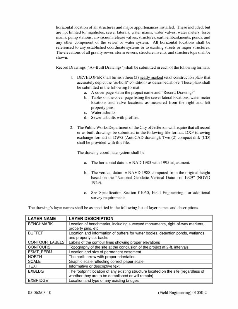
The drawing’s layer names shall be as specified in the following list of layer names and descriptions.
LAYER NAME LAYER DESCRIPTION
BENCHMARK Location of benchmarks, including surveyed monuments, right-of-way markers, property pins, etc
BUFFER Location and information of buffers for water bodies, detention ponds, wetlands, and property set-backs
CONTOUR_LABELS Labels of the contour lines showing proper elevations
CONTOURS Topography of the site at the conclusion of the project at 2-ft. intervals
ESMT_PERM Location and size of permanent easement
NORTH The north arrow with proper orientation
SCALE Graphic scale reflecting correct paper scale
TEXT Informative or descriptive text
EXBLDG The footprint location of any existing structure located on the site (regardless of whether they are to be demolished or will remain)
EXBRIDGE Location and type of any existing bridges

05-062/03-10 (Field Engineering) 01050-3
EXCL The centerlines of any existing roads within the site with road names
EXCOMM Location of any existing overhead or underground telephone lines, cable lines, fiber optics, cable boxes, pedestals or utility poles
EXCONTOURS Topography of the site prior to any grading, all contour lines showing proper elevations at 2-ft. intervals
EXCREEK Location of any existing creek, stream, pond, lake, or any other water body
EXCURB Location of curb lines of any existing road within the site
EXDITCH Location of the centerline of any existing ditch
EXEOG Location of existing edge of gravel, including roads, parking, and driveways
EXEOP Location of existing edge of pavement, including roads, alleys, parking, loading docks or driveways
EXFENCE Location and type of any existing fences
EXFLOOD-LIMITS Location and information of any existing flood limits
EXGAS Location, type and size of any existing natural gas lines, valves or meters
EXGUARD Location of any existing guard rails
EXPL Location of existing property lines
EXPOWER Location of any existing power lines, electricity transmission lines, transformers, or utility poles
EXRAIL Location and information of any existing railways
EXRW Location and information for existing right-of-ways
EXSAN Location and information for existing sanitary sewer on the downstream manhole, upstream manhole and sewer line type and size
EXSTORM Location and information for existing storm sewer of the downstream manhole, upstream manhole, pipe types and sizes, culverts, inlets, headwalls, and inverts
EXTREES Location of any existing tree lines, trees bushes, shrubs or miscellaneous landscaping (regardless of whether they are to be demolished or will remain)
EXWALKS Location of any existing sidewalks
EXWATER Location, size and type of existing waterlines, water valves, water meters and fire hydrants
ABBLDG Footprint of the building(s) located at the site with the finished floor elevation- to include awnings, out-buildings, etc.
ABCL Road centerlines of any new or adjusted roads added to the development
ABCURB Road curb lines of any new or adjusted road added to the development
ABDITCH Centerline of any new ditches added to the development
ABEOP Location of any new or adjusted edge of pavement, including roads, alleys, parking, loading docks or driveways
ABFENCE Location and type of any new fences
ABFLOOD-LIMITS Location and information of any new flood limits
ABGAS Location, type and size of natural gas lines, valves or meters
ABGUARD Location of guard rails
ABPOWER Location of all power lines, electricity transmission lines, transformers, or utility poles
ABRAIL Location and information of railways
ABSAN Location and information on the sanitary sewer piping and manhole tops and inverts
ABSTORM Location and information on the storm sewer pipe types and sizes, manhole tops, inverts, culverts, inlets and headwalls
ABTREES Location of tree lines, trees bushes, shrubs or miscellaneous landscaping
ABWALKS Location of all sidewalks within the site
ABWATER Location, size and type of waterlines, water valves, water meters and fire hydrants on the site
05-062/03-10 (Field Engineering) 01050-4
These exact layer names shall be used. If additional layers are needed, they shall be named and a description
shall be provided. This description must be included on the media with the drawing and must be in .TXT
(ASCII Text) format.
Layer names beginning with EX define conditions as they existed PRIOR to beginning of construction.
Layer names beginning with AB reflect the site condition at the conclusion of the project.
END OF SECTION

05-062/03-10 (Abbreviations) 01070-1
SECTION 01070
ABBREVIATIONS/DEFINITIONS
PART 1 GENERAL
1.01 GENERAL
A. Wherever in these Specifications the abbreviations, or pronouns in place of them are used, the
intent and meaning shall be interpreted as specified herein.
1.02 ABBREVIATIONS
AASHTO American Association of State Highway and Transportation Officials
ACI American Concrete Institute
ACPA American Concrete Pipe Association
AISC American Institute of Steel Construction
AISI American Iron and Steel Institute
AITC American Institute of Timber Construction
ANSI American National Standards Institute
APHA American Public Health Association
ASA American Standards Association
ASCE American Society of Civil Engineers
ASTM American Society for Testing and Materials
AWWA American Water Works Association
CFR Code of Federal Regulations
CRSI Concrete Reinforcing Steel Institute
DOT Department of Transportation
EPA Environmental Protection Agency
EPD Environmental Protection Division
FS Federal Specifications
ICEA Insulated Conductor Engineers Association.
IEEE Institute of Electrical & Electronic Engineers.
MSS Manufacturer's Standardization Society of the Valve and Fitting Industry
MUTCD Manual on Uniform Traffic Control Devices
NBS National Bureau of Standards
NCPI National Clay Pipe Institute
NCSA National Crushed Stone Association
NEMA National Electrical Manufacturers Association
NSF National Sanitation Foundation
OSHA Occupational Safety and Health Administration
PCI Prestressed Concrete Institute
RTU Remote Telemetry Unit
SSPC Steel Structures Painting Council
UL Underwriters Laboratories, Inc.
WEF Water Environment Federation
05-062/03-10 (Abbreviations) 01070-2
1.03 DEFINITIONS
CITY:
Refers to the City of Jefferson.
CONTRACTOR:
The licensed utility contractor performing construction work on behalf of the developer.
DEVELOPER:
The person, partnership, firm, or corporation who is executing the project and that has officially applied for
permitting through the CITY.
PART 2 PRODUCTS - Not Used
PART 3 EXECUTION - Not Used
END OF SECTION
05-062/03-10 (Traffic Control) 01570-1
SECTION 01570 TRAFFIC CONTROL PART 1 GENERAL 1.01 SCOPE OF WORK
A. DEVELOPER shall furnish all materials and labor for the installation and continuous maintenance of traffic control devices throughout the project.
B. This item of work shall include furnishing, installing, maintaining, relocating and
removing all traffic control devices used for the purpose of regulating, warning or directing traffic during the construction or maintenance of this project.
C. Upon completion of work, warning devices are to be removed by the DEVELOPER.
1.02 SAFETY
A. The governing factor in the execution and staging of work for this project is to provide the public with the safest possible travel conditions along the roadway through the construction zone. The DEVELOPER shall arrange his operation to keep the closing of any lane of a roadway to an absolute minimum.
B. No work shall be started on any phase of the project until all appropriate traffic control
devices are in place and in operation.
C. DEVELOPER is to take all practical precautions to maintain traffic flow, and provide safety of workers and the general public.
D. At the end of each workday, contractor is to clear the roadway of all dirt and debris and
add additional safety devices to maintain safe travel lanes.
E. When not in use, all traffic control devices shall be removed, placed or covered so as not to be visible to traffic.
1.03 REFERENCES
A. Manual for Uniform Traffic Control Devices (MUTCD) (latest edition).
B. Georgia Department of Transportation (Ga. DOT) Standard Specifications for Construction of Roads and Bridges (latest edition), Section 150.
C. Georgia Department of Transportation (Ga. DOT) Standard Construction Details (latest
edition).

05-062/03-10 (Traffic Control) 01570-2
PART 2 PRODUCTS 2.01 TRAFFIC CONTORL DEVICES
A. Traffic Control Devices include: signs and their supports, signals, pavement markings, barricades with sand bags, channelizing devices, warning lights, arrowboards, flaggers, or any other device used for the purpose of regulating, warning or guiding traffic through the construction zone.
B. All Traffic Control Devices used on this project shall conform to the plans, Ga. DOT
Construction Details and Specifications, and MUTCD.
C. Traffic Control Devices shall be in proper, acceptable condition when in use. Devices which are unclear, damaged, or not correctly positioned shall be promptly restored to fully operational condition.
PART 3 EXECUTION 3.01 PLAN AND PERMITS
A. DEVELOPER is responsible for preparing his/her own traffic control plan an instituting the plan in compliance with all applicable Georgia DOT requirements.
B. The DEVELOPER shall be responsible for the proper location, installation, and
arrangement of all traffic control devices. Special attention shall be given to advance warning signs during construction operations in order to keep lane assignment consistent with barricade placement at all times. The DEVELOPER shall cover all Traffic Control Devices which are inconsistent with detour or lane assignment patterns during the transition from one construction stage to another.
C. Construction signs referring to daytime lane closures during working hours shall be
removed or covered during non-working hours.
D. The DEVELOPER shall ensure all Traffic Control Devices installed by him are operational 24 hours a day, including weekends and holidays. Provide additional inspections at regular intervals.
E. When traveling in lanes open to public traffic, the contractor's vehicles shall always move
with and not against or across the flow of traffic. These vehicles shall enter or leave work areas in a manner which will not be hazardous to, or interfere with, traffic and shall not park or stop except within designated work areas. Personal vehicles shall not park within the right of way except in specific areas designated by the CITY OF JEFFERSON.
F. Private driveways and parking areas shall be accessible at all times unless temporary
closings are necessary for construction work and the DEVELOPER has notified the affected individuals and has approval from them.
05-062/03-10 (Traffic Control) 01570-3
G. If trenches are to remain open overnight, or for an extended period of time, DEVELOPER is to provide heavy duty cover plates to allow vehicles access.
H. Flaggers are required they are to be adequately trained, qualified and certified by the
Georgia DOT. END OF SECTION

05-062/03-10 (Site Preparation) 02100-1
SECTION 02100
SITE PREPARATION
PART 1 GENERAL
1.01 SCOPE OF WORK
A. WORK to be performed under this section shall consist of clearing and grubbing the site
within the limits of the approved Development Drawings and disposal of all waste materials.
B. WORK also included under this section shall include the removal and replacement of existing
fences and the erection of temporary fences.
C. Definitions
1. Clearing: The removal and disposal of all exposed objectionable matter such as:
trees, brush, logs, buildings, fences, poles, rubbish, loose boulders and other debris
resting on or protruding through the ground surface.
2. Grubbing: The removal and disposal of all objectionable matter such as: logs, poles,
stumps, structures, boulders, rubbish, and other debris which is embedded in the soil.
1.02 REGULATORY REQUIREMENTS
A. Conform to applicable code for disposal of debris.
B. Conform to local Fire Department Codes for burning debris on site. DEVELOPER shall
obtain all necessary permits prior to burning on site.
PART 2 PRODUCTS
2.01 MATERIALS
A. Materials used for protection of trees and vegetation to remain during clearing operations
shall be at DEVELOPER'S option. Materials chosen shall ensure maximum protection to
vegetation and comply with the Georgia Manual for Erosion and Sediment Control.
B. Materials used for the repair of trees and vegetation damaged outside clearing limits shown on
Drawings shall be at DEVELOPER'S option but must be approved by the CITY prior to use.
C. Herbicides shall not be used unless written approval is given by the CITY.
D. Explosives shall not be used unless necessary permits are obtained from all Authorities having
jurisdiction.
E. Materials used for the replacement or relocation of existing fences shall be of equal or
superior quality to those fence materials existing prior to construction unless specified
otherwise on the plans.

05-062/03-10 (Site Preparation) 02100-2
PART 3 EXECUTION
3.01 CLEARING
A. No tree, shrub, or other landscaping plants shall be removed unless absolutely necessary for
the construction of the proposed improvements. All shrubs or landscaping plants removed or
damaged during construction shall be replaced by the DEVELOPER at his expense, with
landscaping approved by the CITY.
B. Limits of clearing shall be contained within the areas within Right-of-way, Easement and
Construction limits as shown on the approved Development Drawings.
C. Existing fences that, at the direction of the CITY, can be reused shall be carefully removed
and stored at such a distance they shall not be damaged by construction activity.
D. Fences that cannot be reused shall be removed to such a distance to allow construction
activity and shall be replaced with new materials similar to existing fences upon completion
of construction.
3.02 GRUBBING
A. The limits of grubbing shall be contained within Right-of-way, Easement and Construction
limits as shown on the approved Development Drawings.
B. Stumps and roots shall be grubbed and removed to a depth not less than 2 feet below existing
grade or bottom of foundation structure.
C. All holes or cavities which extend below the subgrade elevation of proposed WORK shall be
filled with crushed rock or other suitable material and compacted to the same density as the
surrounding material.
3.03 PROTECTION
A. Streets, roads, adjacent property, and other works to remain shall be protected throughout the
work in accordance with local laws and ordinances.
B. DEVELOPER shall make every effort to protect existing bench marks, R/W markers,
monuments, iron pins, property corner markers, etc. If any are disturbed or destroyed,
CONTRACTOR shall provide services of a registered land surveyor to replace the markers.
C. No trees shall be cut outside of areas designated without specific approval of the CITY, and
any trees designated shall be protected from damage by DEVELOPER's construction
operations.
D. Existing trees and other vegetation to remain shall be protected as directed by the CITY:
1. Trees shall be protected by fencing, barricades, or wrapping. Trees which are
trimmed are to be treated with a tree dressing.
05-062/03-10 (Site Preparation) 02100-3
2. Shrub and bushes shall be protected by fencing, barricades, or wrapping. Wrapping
of bushes and shrubs with plastic film will not be permitted.
3. Shallow-rooted plants shall be protected at ground surface under and in some cases
outside the spread of branches by fencing, barricades, or ground cover protection.
E. In the event that archaeological resources are uncovered, DEVELOPER shall notify the CITY
OF JEFFERSON prior to proceeding with WORK.
F. DEVELOPER is to erect temporary fences as necessary to preserve the privacy of all affected
property owners whose existing fences are being removed or relocated. Temporary fences
shall be of sufficient strength and quality to prevent escape of animals and livestock and to
prevent the intrusion of animals and people.
G. It is DEVELOPER's responsibility to coordinate the removal and erection of fences with each
affected property owner and to maintain any temporary and relocated fences throughout the
contract period.
H. DEVELOPER shall assume all costs incurred by any property owner in the loss of animals or
livestock due to an insufficiency of replaced or temporary fences during the contract period
and maintenance period thereafter.
I. It is the DEVELOPER's responsibility to secure any insurance necessary to protect himself in
the event of loss or damage to any animals, livestock and property for the duration of the
project and maintenance period.
3.04 DISPOSAL
A. DEVELOPER shall remove and dispose of all excess material resulting from clearing or site
preparation operations. DEVELOPER shall dispose of such materials in a manner acceptable
to the CITY OF JEFFERSON at an approved location where such materials can be lawfully
disposed.
B. DEVELOPER may, at no cost, retain any materials of value from clearing operations for his
own use or disposal by sale unless otherwise stated in these Specifications. Such material
shall be removed from construction area before completion of WORK. The CITY OF
JEFFERSON assumes no responsibility for protection or safekeeping of any materials so
retained by DEVELOPER.
C. Burning will be permitted if the required permits have been acquired from the local Fire
Department. Burning will be permitted only at times when conditions are considered
favorable for burning and at locations approved by proper State or local authorities. Materials
to be burned shall be piled neatly and, when in a suitable condition, shall be burned
completely. Piling for burning shall be done in such a manner and in such locations as to
cause the least fire risk. All burning shall be so thorough that the materials are reduced to
ashes. No logs, branches, or charred pieces shall be permitted to remain. DEVELOPER shall
at all times take special precautions to prevent fire from spreading to areas beyond the limits
of cleared areas and shall have available at all times, suitable equipment and supplies for use
in preventing and suppressing fires. Unguarded fires will not be permitted.
05-062/03-10 (Site Preparation) 02100-4
D. Material to be removed from site shall be removed as it accumulates to prevent any unsightly
spoil areas.
END OF SECTION

05-062/03-10 (Earthwork for Utilities) 02225-1
SECTION 02225
EARTHWORK FOR UTILITIES
PART 1 GENERAL
1.01 SCOPE OF WORK
Work under this section shall include all operations necessary for excavating, backfilling and
compaction of material necessary for the construction of pipelines and all appurtenant facilities
including sewage pump station, concrete saddles, pipe protection, etc., and for the disposal of waste
and unsuitable materials.
1.02 RELATED WORK
A. Section 02660 – Water Distribution System
B. Section 02732 – Sanitary Sewer Forcemain
C. Section 02736 – Sanitary Sewer
1.03 REFERENCES
A. American Society for Testing and Materials (ASTM), American Water Works Association
(AWWA), Annual Book of Standards
1. ASTM D 698, Test Method for Laboratory Compaction Characteristics of Soil Using
Standard Effort (12,400) ft-lbf/ft3).
2. ASTM D2167, Standard Test Method for Density and Unit Weight of Soil in Place by
the Rubber Balloon Method
3. ASTM D1556, Standard Test Method for Density and Unit Weight of Soil in Place by
the Sand-Cone Method
4. ASTM D 2321, Standard Practice for Underground Installation of Thermoplastic Pipe for
Sewers and Other Gravity-Flow Applications.
5. AWWA C600, Standard for Installation of Ductile-Iron Water Mains and Their
Appurtenances.
6. AWWA C150, American National Standard for the Thickness Design of Ductile-Iron
Pipe
7. ASTM D2487, Standard Practice for Classification of Soils for Engineering Purposes

05-062/03-10 (Earthwork for Utilities) 02225-2
B. Occupational Safety and Health Administration (OSHA), Code of Federal Regulations 29
CFR Part 1926, Subpart P – Excavation, latest revision.
PART 2 PRODUCTS
2.01 BEDDING AND HAUNCHING STONE
A. Class IA or IB aggregate materials in accordance with ASTM D 2321 for gravity sewer, wet
trench conditions, under roads, structures and driveways.
B. For PVC water line (applies to special repairs and cases only; waterlines are DIP only),
CONTRACTOR shall use reused or imported Class II, III or IVA materials in accordance
with ASTM D2321. Materials shall be free of stone, clods, broken rock, or concrete larger
than 1.5 inches in largest dimension, organic matter, rubbish, or other unsuitable material for
all other trench conditions not mentioned in Paragraph 2.01.A, unless otherwise directed by
CITY.
2.02 INITIAL BACKFILL
Reused or imported earth free of stone, clods, broken rock, or concrete ,or organic matter, rubbish, or
other unsuitable material.
Soil types shall be in accordance with ASTM D2487, and the Unified Soil Classification System.
Backfill Classification shall be in accordance with ASTM D2321. Suitable Subsoil: Reused and/or
imported free of stone larger than 3 inch size, and debris. For backfill supporting structures and
piping, Unified Soil Classification System (USCS) Groups GW and GP compacted to 97% Modified
Proctor per ASTM D-1557. For backfill under roadways, pavement and sidewalks, USCS Groups
GW and GP compacted to 98% Standard Proctor, Groups GM, GC, SW, SP, and SM compacted to
98% Standard Proctor, USCS Group SC compacted to 99% Standard Proctor, and USCS Groups ML
and CL compacted to 100% Standard Proctor per ASTM D-698. For backfill not supporting any type
of structure, paving, or sidewalk, Groups GW, GP, GM, and GC compacted to 90% Standard Proctor,
Groups SW, SP, and SM compacted to 91% Standard Proctor, Groups ML, and CL compacted to 92%
Standard Proctor, and Groups OL, MH, CH, and OH compacted to 93% Standard Proctor per ASTM
D-698. Unsuitable soil: USCS Groups MH, CH, OL, OH, and PT.
2.03 FINAL BACKFILL
Reused or imported earth free of stone, clods, broken rock, or concrete larger than 3 inches in largest
dimension, or organic matter, rubbish, or other unsuitable material.
PART 3 EXECUTION
3.01 INSPECTION

05-062/03-10 (Earthwork for Utilities) 02225-3
A. Verify bedding and backfill material to be used are acceptable. Do not use frozen material.
B. Verify areas to be backfilled are free of debris, snow, ice, or water, and surfaces are not
frozen.
3.02 PREPARATION
A. Identify required lines, levels, contours, and datum.
B. When necessary, compact subgrade surfaces to density requirements for backfill material.
3.03 SHEETING, SHORING AND BRACING
A. CONTRACTOR shall be responsible for supporting and maintaining all excavations required
even to the extent of sheeting and shoring the sides and ends of excavations with timber or
other supports. All sheeting, shoring and bracing shall have sufficient strength and rigidity to
withstand the pressure exerted and to conform with OSHA 29 CFR 1926,
Subpart P – Excavations, latest revision.
B. Excavations adjacent to existing or proposed utilities, buildings and structures, or in paved
streets or alleys shall be sheeted, shored and braced adequately to prevent undermining
beneath or subsequent settlement of such structures or pavements. Underpinning of adjacent
utilities and structures shall be done when necessary to maintain utilities and structures in safe
condition. The CONTRACTOR shall be held liable for any damage resulting to such utilities,
structures or pavements as a result of his operations.
C. The need and adequacy of sheeting, shoring, bracing, or other provisions to protect men and
equipment in a trench or other excavation shall be the sole and exclusive responsibility of
CONTRACTOR.
D. Moving trench boxes or sheeting: When using moveable trench support, care should be taken
so not to disturb the pipe location, joints, or embedment. Removal of any trench protection
below the top of the pipe and within the dimensions of the trench shown on the construction
details (for Class 2, 4, and 5 Bedding) shall be prohibited after pipe embedment is compacted.
Therefore, moveable trench supports shall only be used in wide trench construction where
supports extend below the top of the pipe, or on a shelf above the pipe installed in a narrow
trench in accordance with construction details. Any voids left in the embedment material by
support removal shall be carefully filled with Class IA or IB aggregate materials and
compacted.
3.04 EXCAVATION
A. Trench Excavation
05-062/03-10 (Earthwork for Utilities) 02225-4
1. Trench excavation shall consist of the removal of materials necessary for the
construction of pipelines and all appurtenant facilities including collars, concrete
saddles, and pipe protection called for on Drawings.
2. Excavation for pipelines shall be made in open cut unless otherwise shown on
Drawings. Trenches shall be cut true to lines and grades shown on Drawings.
Minimum pipe cover shall be 48” measured from the top of pipe to the ground
surface.
3. Use of motor-powered trenching machine will be permitted but full responsibility for
the preservation, replacement, and/or repair of damage to any existing utility services
and private property shall rest with CONTRACTOR.
4. Bell holes for bell and spigot pipe and/or mechanical joint pipe shall be excavated at
proper intervals so the barrel of the pipe will rest for its entire length upon the bottom
of the trench or bedding material.
5. Pipe trenches shall not be excavated more than 400 feet in advance of pipe laying and
all work shall be performed to cause the least possible inconvenience to the public.
Adequate temporary bridges or crossings shall be constructed and maintained where
required to permit uninterrupted vehicular and pedestrian traffic. Final grading and
cleanup shall be continuous throughout the project. CONTRACTOR shall backfill
all trenches at the end of each day.
6. Unless otherwise specified herein or shown on Drawings, wherever pipe trenches are
excavated below elevation shown on Drawings, CONTRACTOR, at his own
expense, shall fill the void thus made to proper grade with bedding and haunching
material in accordance with Part 2.01A.
7. In all cases where materials are deposited along open trenches they shall be placed so
that no damage will result to the WORK and/or adjacent property in case of rain or
other surface wash.
8. Remove soft, spongy, or otherwise unstable materials encountered at elevation of
pipe which will not provide a firm foundation for the pipe. Extend bedding depth as
necessary to reach firm materials.
B. Any unauthorized excavation shall be corrected at the CONTRACTOR/DEVELOPER's
expense.
C. Protect bottom of excavations and soil adjacent to and beneath foundations from frost.
D. Grade top perimeter of excavation to prevent surface water run-off into excavation.
E. Notify CITY and ENGINEER of unexpected subsurface conditions and discontinue work in
affected area until notification to resume work.

05-062/03-10 (Earthwork for Utilities) 02225-5
F. Trench widths shall be in accordance with construction details for Class 2, 4, and 5 Bedding.
3.05 DEWATERING
A. CONTRACTOR shall provide and maintain at all times during construction, ample means
and devices with which to promptly remove and properly dispose of all water from any source
entering the excavations or other parts of the WORK. Dewatering shall be accomplished by
methods which will ensure a dry excavation and preservation of final lines and grades of
bottoms of excavations. Methods of dewatering may include sump pumps, well points, deep
wells, or other suitable methods which do not damage or weaken structures, foundations, or
subgrades. Shallow excavations may be dewatered using open ditches provided such ditches
are kept open and free-draining at all times. Dewatering methods used shall be acceptable to
ENGINEER. Footing pits or trenches shall be protected by small earth dikes and plastic
covers when they are left open in rainy weather.
B. When significant (more than 30 L.F. continuously in a trench) ground water is encountered in
soils containing fines, the CONTRACTOR shall notify the CITY. In these areas, the trench
shall be lined with an approved filter fabric between the bedding and haunching material and
the trench walls to reduce the affects of migration of fines which can diminish pipe support.
C. Unless specifically authorized by CITY, groundwater encountered within the limits of
excavation shall be depressed to an elevation not less than twelve (12) inches below the
bottom of such excavation before pipe laying or concreting is started and shall be so
maintained. No concrete structures shall be exposed to unequal hydrostatic forces until the
concrete has reached its specified 28-day strength. Water shall not be allowed to rise above
bedding during pipe laying operations. CONTRACTOR shall exercise care to prevent
damage to pipelines or structures resulting from flotation, undermining, or scour. Dewatering
operations shall commence when ground or surface water is first encountered and shall be
continued until such times as water can safely be allowed to rise in accordance with
provisions of this section.
D. Standby pumping equipment shall be kept on the job site. A minimum of one standby unit
(one for each ten in the event well points are used) shall be available for immediate
installation should any pumping unit fail. Installation of well points or deep wells shall be
adequately sized to accomplish the WORK.
E. CONTRACTOR shall not operate dewatering devices (i.e., pumps, etc.) before the hour of
8:00 AM and after the hours of 8:00 PM in a residential area unless otherwise approved by
CITY.
F. If foundation soils are disturbed or loosened by the upward seepage of water or an
uncontrolled flow of water, the affected areas shall be excavated and replaced with foundation
backfill. Foundation backfill shall be placed in bottom of trench to within 6" of the bottom of
pipe. Six (6) inches of bedding stone shall be placed over the top of the foundation backfill.

05-062/03-10 (Earthwork for Utilities) 02225-6
G. CONTRACTOR shall dispose of water from the WORK in a suitable manner without damage
to adjacent property. Conveyance of water shall be such as to not interfere with construction
operations or surrounding property owners. No water shall be drained into WORK built or
under construction. CONTRACTOR will be held responsible for the condition of any pipe or
conduit which he may use for drainage purposes, and all such pipes or conduits shall be left
clean and free of sediment.
H. Storm water runoff shall be controlled by means of temporary erosion control methods.
I. Water shall be disposed of in such a manner as not to be a menace to public health and in
accordance with applicable Environmental Protection Agency, Corps of Engineers, and State
Environmental Protection Division standards and permits.
3.06 BEDDING/BACKFILLING
A. The backfilling of trenches shall be started immediately after construction of same has been
viewed by the CITY. Bedding shall be aggregate and backfill material shall be earth or
aggregate in accordance with Part 2 and the Details. Material shall be deposited in the initial
horizontal layer to the spring line of the pipe (before compaction) on each side of the pipe.
The initial layer shall be thoroughly tamped or rammed around the pipe until the initial layer’s
density is equal to the density of the adjacent undisturbed soils. The second bedding material
layer shall be deposited horizontally to a depth to provide a cover of not less than 12 inches
over top of pipe. The remainder of the backfill shall be placed in horizontal layers 18 inches
(maximum) in depth. The second and subsequent bedding/backfill layers shall be compacted
by compaction tools to a density equal to the density of the adjacent undisturbed soils, except
under roads, structures, and driveways.
B. Compact aggregate and soil backfill under roads, parking lots, structures, and driveways to a
minimum of 95% of maximum dry density at not less than 2% below nor more than 2% above
the optimum moisture content as determined by ASTM D 698. The top 12 inches shall be
compacted to 100 percent of maximum dry density. Consolidation by saturation or ponding
will not be permitted.
C. All backfilling shall be done in such a manner that the pipe or structure over or against which
it is being placed will not be disturbed or injured. Any pipe or structure injured, damaged or
moved from its proper line or grade during backfilling operations shall be removed and
repaired to the satisfaction of OWNER and then re-backfilled.
D. Backfilling shall not be done in freezing weather except by permission of the CITY, and shall
not be done with frozen material or upon frozen materials.
E. All backfilling shall be left with smooth, even surfaces, properly graded and shall be
maintained in this condition until final completion and acceptance of the work. Where
directed by the CITY, the backfill shall be mounded slightly above the adjacent ground.
F. Leave stockpile areas completely free of excess fill materials. After construction and cleanup,
stockpile areas shall be seeded.

05-062/03-10 (Earthwork for Utilities) 02225-7
G. Use “Class 5” bedding in all wet trenches and under roads/driveways, regardless of pipe
material. Use “Class 5” bedding for all PVC sewer.
H. Use “Class 4” bedding for DIP gravity sewer.
I. Use “Class 2” bedding for DIP waterline/pressure lines.
3.07 SUBSURFACE OBSTRUCTIONS
A. In excavating, backfilling, and laying pipe, case must be taken not to remove, disturb, or inure
any existing water, telephone, gas pipes, storm drainage pipe, headwalls or catch basins, or
other conduits or structures, without the approval of the CITY. If necessary, the
CONTRACTOR at his own expense, shall sling, shore up, and maintain such structures in
operation, and shall repair any damage to them. Before final acceptance of the work, he shall
return all such structures to as good condition as before the work started.
B. The CONTRACTOR shall give sufficient notice to the interested utility of his intention to
remove or disturb any pipe, conduit, etc., and shall abide by their regulations governing such
work. In the event that any subsurface structure becomes broken or damaged in the execution
of the work, the CONTRACTOR shall immediately notify the proper authorities, and shall be
responsible for all damage to persons or property caused by such breaks. Failure of the
CONTRACTOR to promptly notify the affected authorities shall make him liable for any
needless loss so far as interference with the normal operation of the utility.
C. When pipes or conduits providing service to adjoining buildings are broken during progress
of the work, the CONTRACTOR shall repair them at once.
D. Delays such as would result in buildings or residences being without services overnight or for
a needlessly long period during the day will not be tolerated. Should it become necessary to
move the position of a pipe, conduit or structure, it shall be done by the CONTRACTOR in
strict accordance with the instructions given by the CITY or the utility involved.
3.08 BORROW EXCAVATION
Wherever the backfill of excavated areas or the placement of embankments or other fills require
material not available at the site, suitable material shall be obtained from other sources. This may
require the opening of borrow pits at points not immediately accessible to the WORK. In such cases,
CONTRACTOR shall make arrangements with the property owner and shall pay all costs incident to
the borrowed material including royalties, if any, for the use of the material. Before a borrow pit is
opened, the quality and suitability of the material to be obtained shall be approved by the CITY. Any
soil tests required for approval of the borrowed material proposed, shall be at the DEVELOPER's
expense.
3.09 DISPOSAL OF WASTE AND UNSUITABLE MATERIALS
05-062/03-10 (Earthwork for Utilities) 02225-8
A. Materials removed by excavation, which are suitable for the purpose, shall be used to extent
possible for backfilling pipe trenches and for making embankment fills, subgrades or for such
other purposes as may be shown on Drawings. Materials not used for such purposes shall be
considered waste material and shall be disposed of at the CONTRACTOR's expense.
B. Waste materials shall be spread in uniform layers and neatly leveled and shaped. Spoil banks
shall be provided with sufficient and adequate openings to permit surface drainage of adjacent
lands.
C. Unsuitable materials, consisting of rock, wood, vegetable matter, debris, soft or spongy clay,
peat, and other objectionable material so designated by the CITY, shall be removed from the
work site and disposed of by CONTRACTOR at his expense.
D. No waste material shall be dumped on private property unless written permission is furnished
by owner of property and unless a dumping permit is issued from local jurisdiction.
3.10 TESTING
A. Compaction of fill and backfill to the specified moisture-density relationship of soils shall be
verified by in-place density tests using ASTM D 2167, D1556 or other ASTM in-place
density tests approved by the CITY. Maximum density determination and in-place density
tests shall be performed by a registered geotechnical engineering representative employed by
the DEVELOPER. Frequency and location of tests shall be adequate to ensure proper
compaction has been achieved.
B. The CITY shall reserve the right to employ and assign its own a registered geotechnical
engineering representative to verify and conduct compaction testing if so inclined.
C. Evidence/documentation of the DEVELOPER’s testing shall be submitted to the CITY at the
CITY’s request.
D. Areas not meeting the required compaction shall be recompacted until the desired degree of
compaction is achieved. All costs associated with re-testing failed areas of compaction shall
be paid for by the DEVELOPER.
3.11 PROTECTION
Protect excavation by shoring, bracing, sheet piling, underpinning, or other methods required to
prevent cave-in of loose soil into excavation. Protection shall be in accordance with OSHA 29 CFR
1926, Subpart P-Excavations, latest revision.
3.12 FINAL GRADING
A. After other earthwork operations have been completed, sites of all structures and
embankments shall be graded to finished grade as shown on the Drawings. Grading
operations shall be so conducted that materials shall not be removed or loosened beyond
required limits. Finished surfaces shall be left in smooth and uniform planes such as are
05-062/03-10 (Earthwork for Utilities) 02225-9
normally obtainable from use of hand tools. If CONTRACTOR is able to obtain required
degree of evenness by means of mechanical equipment, he will not be required to use hand
labor methods. Slopes and ditches shall be neatly trimmed and finished.
B. Unless otherwise specified or shown on the Drawings, all finished ground surfaces shall be
graded and dressed to present a surface varying not more than plus or minus 0.10 foot. Any
finished surfaces resulting in inadequate drainage or washouts shall be corrected by the
CONTRACTOR at his expense.
3.13 SETTLEMENT
A. CONTRACTOR shall be responsible for all settlement of backfill, fills, and embankments
which may occur during warranty period.
B. CONTRACTOR shall make, or cause to be made, all repairs or replacements made necessary
by settlement within 30 days after receipt of written notice from CITY.
END OF SECTION
05-062/03-10 (Rock Removal) 02227-1
SECTION 02227
ROCK REMOVAL
PART 1 GENERAL
1.01 SCOPE OF WORK
A. Removal of all rock materials discovered during excavation for the purpose of
construction. Removal shall include drilling and/or blasting incidental thereto and
disposal of excavated materials.
B. When necessary for prosecution of the WORK, the use of explosives to assist rock
removal may be exercised by DEVELOPER provided this use is in compliance with all
local, State, Federal and other Governmental regulations applying to transportation,
storage, use and control of explosives.
1.02 RELATED WORK
A. Section 02225 - Earthwork for Utilities
1.03 REFERENCES
A. NFPA 495 - Code for the Manufacture, Transportation, Storage, and Use of Explosive
Materials.
B. OSHA 2207 - Construction Industry Standards, Subpart T - Demolition.
C. Rules and Regulations of Safety Fire Commissioner, Chapter 120-3-10.
1.04 QUALITY ASSURANCE
A. Explosives Firm: Company specializing in explosives for disintegration of subsurface
rock with documented experience.
1.05 REGULATORY REQUIREMENTS
A. Conform to applicable code, including Rules and Regulations of Safety Fire
Commissioner, Chapter 120-3-10, for explosive disintegration of rock.
B. Obtain permits from authorities having jurisdiction before explosives are brought to site
or drilling is started.
C. All explosives shall be stored securely in compliance with all laws and ordinances, and
all such storage places shall be clearly marked DANGEROUS EXPLOSIVES. Blasting
caps, electric blasting caps, detonating primers, and primed cartridges shall not be stored
in the same magazine with other explosives or blasting agents. Locked storage shall be
provided satisfactory to the CITY OF JEFFERSON, never closer than allowed by the
Safety Fire Commissioner.

05-062/03-10 (Rock Removal) 02227-2
PART 2 PRODUCTS
2.01 MATERIALS
A. Rock (Definition): Solid mineral material with a volume in excess of 1/2 cu yd that
cannot be broken down and removed by use of heavy construction equipment, such as a
Caterpillar 225 or equivalent, having a bucket curling force rated at not less than 25,700
pounds, bulldozer such as a Caterpillar D8K equipped with single tooth hydraulic ripper,
3/4 cu yd capacity power shovel, rooters, etc., and without drilling or blasting. Materials
which can be loosened with a pick, hard pan, boulders less than 1/2 cu yd in volume,
chert, clay, soft shale, soft and disintegrated rock and any similar material shall not be
considered as rock. (All materials to be considered unclassified or common excavation)
B. Explosives: Shall be suitable for intended purposes at the DEVELOPER's option subject
to review by the CITY.
C. Delay Devices: Type recommended by explosives firm to be used as accessory to
explosives. Subject to review by the CITY.
D. Blasting Mat: When the use of explosives is necessitated during prosecution of the
WORK, DEVELOPER shall incorporate the use of blasting mats of type recommended
by explosives firm to lessen the danger of projectiles occasionally resultant from blasting
of rock.
PART 3 EXECUTION
3.01 INSPECTION
A. Rock in utility trenches shall be excavated over the horizontal limits of excavation and to
depths as follows:
Size of Pipeline
(Inches)
Depth of Excavation Below Bottom
of Pipe (Inches)
Less than 4
6
4 to 6
8
8 and over
12
Space below grade for pipe shall then be backfilled with 3/4-inch crushed rock or gravel
or other approved materials and tamped to proper grade.
3.02 ROCK REMOVAL - MECHANICAL METHOD
A. Excavate for and remove rock by the mechanical method.
05-062/03-10 (Rock Removal) 02227-3
B. Where pipes are constructed on concrete cradles, rock shall be excavated to bottom of
cradle as shown on plans.
C. Where rock foundation is obtained at grade for over 50 percent of area of any one
structure, the portion of foundation that is not rock shall be excavated below grade to
reach a satisfactory foundation of rock. The portion below grade shall be backfilled with
Class C concrete.
D. Where rock foundation is obtained at grade for less than fifty (50%) of any one structure
and satisfactory rock cannot be found over the remaining area by reasonable additional
excavation, the rock shall be removed for a depth of twelve (12) inches below grade and
the space below grade shall be backfilled with crushed stone as specified for pipelines.
E. Rock excavation near existing pipelines or other structures shall be conducted with
utmost care to avoid damage. Injury or damage to other structures and properties shall
be promptly repaired to the satisfaction of the CITY and by DEVELOPER at his own
expense.
F. Remove excavated material from site.
G. DEVELOPER shall correct excess rock removal by backfill to grade with Class C (3000
psi) concrete in accordance with backfilling and compaction requirements of Section
02225 (Earthwork for Utilities), at his own expense.
3.03 ROCK REMOVAL - EXPLOSIVES METHODS
A. The DEVELOPER shall notify any owners of adjacent buildings or structures, and any
public utility owners having structures or other installations above or below ground, in
writing prior to use of explosives. Such notice shall be given sufficiently in advance so
that they may take such steps as they may deem necessary to protect their property from
injury and/or damage.
B. Rock excavation by use of explosives shall be conducted with due regard for safety of
persons and property in the vicinity and in strict conformance with requirements of local,
State and Federal ordinance, laws and regulations of the Safety Fire Commissioner.
C. Blasting shall be conducted so as not to endanger persons or property, and whenever
required, the blast shall be covered with mats or otherwise satisfactorily confined. The
DEVELOPER shall be held responsible for and shall make good any damage caused by
blasting or accidental explosions.
D. The DEVELOPER shall permit only authorized and qualified persons to handle and use
explosives.
E. Smoking, firearms, matches, open flame lamps, and other fires, flame or heat producing
devices and sparks shall be prohibited in or near explosive magazines or while
explosives are being handled, transported or used.
F. No person shall be allowed to handle or use explosives while under the influence of
intoxicating liquors, narcotics, or other dangerous drugs.
05-062/03-10 (Rock Removal) 02227-4
G. All explosives shall be accounted for at all times. Explosives not being used shall be
kept in a locked magazine, unavailable to persons not authorized to handle them. The
DEVELOPER shall be held responsible for maintaining an inventory and use record of
all explosives. Appropriate authorities shall be notified of any loss, theft, or
unauthorized entry into a magazine.
H. No explosives or blasting agents shall be abandoned.
I. DEVELOPER's employees authorized to prepare explosive charges or conduct blasting
operations shall use every reasonable precaution including, but not limited to, visual and
audible warning signals, flags, or barricades, to ensure safety.
J. A seismograph shall be used at the nearest structure during blasting events that are
within 750 feet of the nearest house, public building, school, church, commercial or
institutional building and roadway. The velocity/shock wave shall not exceed the
established limits of U.S. Bureau of Mines RI 8507; appendix (b).
Exception: Where all pedestrian and vehicular traffic on a roadway can be restricted to a
distance of 750 feet or greater from the blast site at the time of the firing of the blast or
where a variance is issued by the State Fire Marshal’s Office.
K. Disintegrate rock and remove from excavation.
L. Cut away rock at excavation bottom to form level bearing.
M. Remove shale layers to provide sound and unshattered base for pipe foundations.
N. Remove excavated material from site.
O. Correct unauthorized rock removal or overbreak in accordance with backfilling and
compaction requirements at his own expense.
3.04 FIELD QUALITY CONTROL
Provide for visual inspection of bearing surfaces and cavities formed by removed rock for
inspection by the CITY OF JEFFERSON.
END OF SECTION

05-062/03-10 (Boring and Jacking) 02300-1
SECTION 02300
BORING AND JACKING
PART 1 GENERAL
1.01 SCOPE OF WORK
A. WORK covered in this section includes furnishing all labor, materials, accessories,
equipment and service required to properly complete pipeline construction using
tunneling or boring and jacking under railroads and state, county, or city highways and
streets, as described herein and/or shown on City’s Standard Details and construction
drawings.
1.02 RELATED WORK
A. Section 02225 - Earthwork for Utilities
B. Section 02660 - Water Distribution Systems
C. Section 02732 - Sanitary Sewer Force Mains
D. Section 02736 - Sanitary Sewer
PART 2 PRODUCTS
2.01 MATERIALS
A. Boring and Jacking
1. Steel casing pipe, sizes 12 inches through 24 inches shall be spiral or straight
seam welded steel pipe conforming to ASTM A 139, Grade A. Minimum wall
thickness of steel pipe for railroad crossings shall be 0.375 inches. Minimum
wall thickness for roadway crossings shall be 0.250 inches.
2. Steel casing shall be bituminous coated on the outside.
3. Minimum Steel Casing Diameters:
Pipe Diameter Minimum Steel Casing
Diameter
6-inch 12-inch
8-inch 16-inch
10-inch 20-inch
12-inch 20-inch
05-062/03-10 (Boring and Jacking) 02300-2
B. Carrier Pipe: As specified under Section 02660 (Water Distribution Systems), Section
02732 (Sanitary Sewer Force Mains), Section 02736 (Sanitary Sewer), and/or as shown
on Drawings. All piping shall be DIP installed through casing with restrained joints as
Section 02660 (Fast-Grip Gasket” or “Field-Lok Gasket)
C. Class "D" (2500 psi) Concrete
PART 3 EXECUTION
3.01 GENERAL
A. Any solidification of embankments, boring heading, or sides shall be the DEVELOPER's
responsibility and shall be done at his own expense.
B. Trench excavation; all classes and types of excavation; the removal of rock, muck,
debris; the excavation of all working pits; and backfill requirements of Section 02220 are
included under this section.
C. Adequate sheeting, shoring, and/or bracing for embankment operating pits and other
appurtenances shall be placed and maintained to ensure that WORK proceeds safely and
expeditiously. Upon completion of required WORK, the sheeting, shoring, and bracing
shall be left in place, cut off, or removed, as designated by the CITY OF JEFFERSON.
D. DEVELOPER shall maintain and operate pumps, well points, and drainage system
equipment to keep work dewatered at all times.
E. Bored installations shall be a bored-hole diameter essentially the same as the outside
diameter of casing pipe to be installed.
F. Casing pipe shall be jacked into boring as soon as possible after boring is made. Lengths
of casing pipe as long as practical shall be used. Joints between sections shall be
completely welded as recommended for joining the particular type of pipe.
G. Once jacking procedure has begun, it should be continued without stopping until
completed, subject to weather and conditions beyond the control of DEVELOPER.
H. Care shall be taken to ensure that casing pipe installed by boring and jacking or open cut
method will be at the proper alignment and grade.
I. Open cut installations, where permitted, shall be in accordance with details and
procedures shown on Drawings.
J. Ends of casing shall be sealed with brick bulkheads using brick and mortar.
K. After casing pipe is installed, the carrier pipe shall be installed exercising care to protect
its coating and lining and maintain its joint integrity. Carrier pipe shall be concentric
and be placed in proper horizontal and vertical alignment using wooden blocking/wedges
or prefabricated pipe collars spaced radially around pipe and secured to remain firmly in
place. Spacing of such blocking or collars shall be no greater than ten (10') feet on
center longitudinally in casing pipe.

05-062/03-10 (Boring and Jacking) 02300-3
3.02 HIGHWAY/ROADWAY CROSSINGS
A. DEVELOPER is responsible for the coordinating and scheduling of all construction
work within State, County, or City highways, or railroad rights-of-way prior to, during,
and after utility installation.
B. DEVELOPER shall review and coordinate construction methods, materials, and safety
measures with the affected OWNER.
C. For open trench cut installations, DEVELOPER shall be responsible for scheduling and
coordinating all construction work. WORK at one particular crossing shall be completed
with the trench backfilled, compacted, and a temporary crushed stone surface provided
for traffic before any work is started on another such crossing.
D. Installations shall be done to leave free flows in drainage ditches, pipes, culverts, or
other surface drainage facilities of the highway, street, or its connections.
E. Where sodding is disturbed by excavation or backfilling operation, such areas shall be
replaced by mulch sodding on slopes 5 percent or less. Slopes over 5 percent shall be
replaced with block sodding. No separate payment shall be made for sodding which
shall be included in the bid prices for installation of pipe.
F. Trench excavation within the right-of-way, but not under pavement, shall be backfilled
as described in Section 02225 (Earthwork for Utilities).
G. Surplus material shall be removed from the right-of-way and the excavation finished
flush with surrounding ground.
H. Grout backfill shall be used for unused bores or abandoned pipes.
I. Boring, jacking, or driving of casing pipes shall be accomplished without jetting,
sluicing, or wetboring.
J. No excavated materials or equipment shall be placed on the pavement or shoulders of
roadways.
K. In no instance will DEVELOPER be permitted to leave equipment (trucks, backhoes,
etc.) on the pavement or shoulder overnight. Construction materials to be installed,
which are on the right-of-way in advance of construction, shall be placed in such a
manner as not to interfere with the safe operation of the roadways.
END OF SECTION

05-062/03-10 (Restoring Pavements) 02575-1
SECTION 02575
RESTORING PAVEMENTS
PART I GENERAL
1.01 SCOPE OF WORK
A. Work included in this Section consists of repair and replacement of pavements
including: concrete, asphalt, surface treatment, and crushed storm or gravel
roadways; sidewalks, curbs and gutters; stabilized shoulders; and driveways.
1.02 RELATED WORK
A. Section 02225 – Excavation, Backfilling and Compaction for Utilities
1.03 QUALITY ASSURANCE
A. Coring and testing of pavement will be performed by DEVELOPER at
DEVELOPER’S’s expense.
1.04 REFERENCES
A. Standard Specifications, Construction of Roads and Bridges, Latest Edition –
Department of Transportation, State of Georgia.
PART 2 PRODUCTS
2.01 GRADED AGGREGATE
A. Shall be sound, durable, graded aggregate base, all of which passes the following,
free of organic matter and debris.
Sieve Size Percent Passing By Weight
Group 1 Aggregates
2 in (50 mm) 100
1 – ½ in (37.5 mm) 97-100
¾ in (19.0 mm) 60-95
No. 10 (2 mm) 25-50
No. 60 (250 µm) 10-35
No. 200 (75 µm) 7-15
From DOT Spec – 815 – 9.A.B.
05-062/03-10 (Restoring Pavements) 02575-2
2.02 CONCRETE
A. Shall be ready-mixed concrete, 3,000 psi.
2.03 BITUMINOUS PRIME
A. Shall conform to Georgia D.O.T. Standard Specifications Section 821.01.
2.04 ASPHALTIC CONCRETE
A. Shall be Hot Mix Asphaltic Concrete conforming to Section 400 of Georgia
D.O.T. Standard Specifications, from a source approved, in advance, by the City
of Jefferson.
PART 3 EXECUTION
3.01 GENERAL
A. Restore all pavement, base, sidewalks, curbs and gutters, shoulders, and
driveways equal to or better than the original, but not less thickness than specified
herein or shown on the Drawings.
B. Carefully backfill any excavated area on which pavement, sidewalks, or curbs and
gutters are to be placed as specified in Section 02225 of these Specifications.
C. All pavement restoration shall be done in accordance with the requirements of the
authorities within whose jurisdiction such pavement is located. All highway
utilities are to be maintained, and work shall conform to the rules and regulations
of the authority, including the use of traffic control signage. The DEVELOPER
shall provide all such bonds or checks which may be required by the highway
authorities to insure proper restoration of paved areas, at no cost to the OWNER.
D. It is the DEVELOPER’s responsibility to coordinate, communicate and comply
with local authority that has jurisdiction. All work shall comply with the
requirements of this local authority.
E. If, prior to the expiration of the period of maintenance, any pavement or gravel
roadways, curbs, or storm drainage structures which have been damaged, due to
undermining, or for any other cause which may be attributed to the work of the
DEVELOPER, the DEVELOPER shall remove such damaged or injured surfaces,
foundations of same, and all loose earth. DEVELOPER shall then backfill with
graded aggregate base, properly compacted; and furnish, place and maintain the
pavement, gravel roadway, curbs, or storm drainage structure as required.
05-062/03-10 (Restoring Pavements) 02575-3
F. Work which the DEVELOPER may perform in connection with the replacement
and repair of damaged roadways or storm drainage structures during the period of
maintenance, shall be done at his expense, in accordance with the rules and
requirements of the authority within whose jurisdiction such pavement is located,
and in accordance with the additional requirements of the specifications, and the
DEVELOPER shall furnish evidence to the CITY that the work has been
completed to the satisfaction of such authority.
G. Before placing any base, pavement, sidewalk or curb and gutter, cut the existing
pavement along the trench line back from the top edges of the ditch line for a
distance of at least twelve inches (12”) on each side of the ditch to allow solid
bearing edges for base and pavement.
H. All cuts shall be made by channeling machine, pneumatic tools, or such other
methods that will furnish a clean cut in the pavement and pavement base without
undue shattering.
1. For pipeline trenches, the repaired area should adhere to the following
procedures:
a. Pavement and trench to be opened as shown in standard details. After
the utility line and any required bedding have been placed, the backfill
and overfill material shall be placed as described in the project
specifications, up to the subbase. At this point, the pavement shall be
cut back at least 12-inches on each side of the trench or to visible
overbreaks, whichever is greater, to a depth of 2-inches with a
concrete saw. Remove pavement as necessary. The subbase material
shall be carefully placed and shaped. Water shall be added as
necessary to provide a damp, but not wet, subbase before the concrete
base is placed. The vertical face of the existing pavement shall be
sprayed with a fine mist of water to moisten the surface. The new
concrete base shall then be poured before this surface dries out. The
base shall be placed with care, making sure it is worked back into all
corners and into the rough surface of the existing pavement.
After the concrete base has cured, the surface of the concrete base and
vertical edges of the existing paving must be clean and dry before the
tack coat is applied. The tack coat shall be applied to the surface of
the new concrete base and brushed into the corners and onto the
vertical edges of the old pavement to provide a bond and to seal out
water. The hot asphaltic plant mix surface material shall be
immediately placed after the surface of the tack coat has dried to the
point that it is sticky to the touch.
I. The DEVELOPER shall provide graded aggregate base over trenches in public
streets promptly after completion of backfill to provide full use of the street with a
05-062/03-10 (Restoring Pavements) 02575-4
minimum of delay. Steel plates shall be placed over the trenches until placement
of concrete or asphalt, as directed on the Contract Drawings is complete.
J. Should settlement, cracks or other indications of failure appear in pavements, the
paving shall be removed to the extent necessary to secure firm, undisturbed
bearing and shall be relaid in a satisfactory manner.
K. Bituminous Paving
1. Transport bituminous concrete paving mixes from an approved mixing
plant to the work site in tight vehicles with metal bottoms previously
cleaned of all foreign materials. All such vehicles shall be suitably
insulated to avoid heat losses. Each load shall be covered or otherwise
protected to prevent cooling and loss of ingredients.
2. Prime base course and place surface course in accordance with Section
400 of the Georgia D.O.T. Standard Specifications. Surface course in
place, compacted thickness shall be 1½” minimum unless otherwise
shown on the Drawings.
3. Dump and spread mixture on primed base with a spreading and finishing
machine so that after compaction, surface will be smooth, of uniform
density, and meet requirements for typical cross-sections shown on the
Drawings. Other placing means may be proposed.
4. Unless otherwise indicated or approved, place all bituminous concrete and
complete initial rolling during daylight hours. Mixtures shall be at a
temperature of between 225 degrees F. and 325 degrees F. when placed.
5. During application take care to prevent the splattering of adjacent curbs,
gutter, concrete paving, and structures. Hand spreading may be employed
where machine is impractical.
6. Bituminous concrete paving finish grades shall be approximately 6” below
adjacent concrete sidewalks, and/or curbs, except as specifically straight
within ½” in 10’ when checked with a straight edge. No “bird baths” will
be allowed.
7. Provide sufficient rollers to obtain the required pavement density.
Continue rolling until no further compression can be obtained and all
roller marks are eliminated.
8. Rollers shall not be permitted to stand on pavement which has not been
fully compacted and which has not cooled to atmospheric temperature. To
prevent adhesion of surface mixture to roller, keep wheels thoroughly

05-062/03-10 (Restoring Pavements) 02575-5
moistened with water; however, an excessive use of water will not be
permitted.
9. Maintain slow enough movement of roller at all times to avoid
displacement of mixture. If any displacement occurs, correct at once by
use of rakes and addition of fresh mixture.
10. Take precautions to prevent dropping of oil, gasoline, or grease on
pavement.
11. Along edges of pavement along curbs, headers, aprons, manholes, valve
boxes and similar places not accessible to roller, thoroughly compact
asphalt with lightly oiled hand-operated vibrating rollers or mechanical
tampers.
12. After final rolling, do not permit vehicular traffic on asphalt pavement
until it has cooled and hardened, and in no case sooner than 6 hours.
L. Surface Treatment
1. Shall conform to triple surface treatment as defined in the Georgia D.O.T.
Standard Specifications, Section 424.
2. DEVELOPER shall select the aggregates and bituminous material to be
used subject to approval of CITY.
3. Aggregates and bituminous material shall conform to, and be applied in
conformance with, Section 424 of Georgia D.O.T. Standard
Specifications.
4. Spread materials at a uniform rate; use hand work where necessary to
insure uniform, adequate cover.
5. Provide sufficient rolling to key the aggregate into bituminous material.
6. Broom surface as necessary.
7. Do not permit traffic on any course until the bituminous material has
cooled and set.
M. Portland Cement Concrete Pavement
1. Shall conform to requirements of Section 430 of Georgia D.O.T. Standard
Specifications. Concrete shall be 4,000 psi.

05-062/03-10 (Restoring Pavements) 02575-6
2. Place concrete in such a manner as to require as little rehandling as
possible.
3. Provide reinforcement equal the original pavement with sufficient ties to
insure an integral slab.
4. Vibrate concrete over its full width and depth.
5. Finish by float or finishing machine, continuously following placement.
3.02 CLEAN UP
A. Before work is accepted by the CITY, remove excess material not used from job
site.
B. Any subsequent settlement of pavement or backfill, or erosion over or in the
trenches shall be replaced or repaired and the surface shall be brought to grade.
C. Any and all items disturbed by the construction shall be restored to original
condition as soon as possible after completion of the work.
END OF SECTION

05-062/03-10 (Manholes) 02601-1
SECTION 02601
MANHOLES
PART 1 GENERAL
1.01 SCOPE OF WORK
A. WORK required under this section consists of all materials, accessories, equipment,
tools, and labor required to install precast concrete standard manholes.
B. Construction of cast-in-place or precast manholes shall conform to ASTM C-478.
1.02 RELATED WORK
A. Section 02225 - Earthwork for Utilities
B. Section 02602 – Coatings for Existing Manholes and Wastewater Structures
C. Section 02603 – Coatings for New Manholes and Wastewater Structures
1.03 REFERENCES
A. ASTM A 48, Standard Specification for Gray Iron Castings.
B. ASTM C 32, Standard Specification for Sewer and Manhole Brick (made from clay or
shale).
C. ASTM C 144, Standard Specification for Aggregate for Masonry Mortar.
D. ASTM C 443, Standard Specification for Joints for Circular Concrete Sewer and Culvert
Pipe, Using Rubber Gaskets.
E. ASTM C 478, Standard Specification for Precast Reinforced Concrete Manhole
Sections.
F. ASTM C 1244, Standard Test Method for Concrete Sewer Manholes by the Negative Air
Pressure (Vacuum) test.
G. ASTM C 923, Standard Specification for Resilient Connectors Between Reinforced
Concrete Manhole Structures, Pipes and Laterals.
H. ASTM C 990, Joints for Concrete Pipe, Manholes, and Precast Box
Sections Using Preformed Flexible Joint Sealants
.
1.04 QUALITY ASSURANCE
A. After delivery to site, materials which have been damaged in transit or are otherwise
unsuitable for use in the WORK, shall be rejected and removed from the site.

05-062/03-10 (Manholes) 02601-2
PART 2 PRODUCTS
2.01 MATERIALS
A. Concrete
1. Concrete, cement, sand and water used in manhole construction shall conform to
the applicable requirements stated in ASTM C-478.
2. Steel reinforcement shall conform to the applicable requirements of ASTM C-
478.
B. Precast Concrete Manholes
1. Precast concrete manholes shall consist of precast reinforced concrete sections, a
conical or flat slab top section, and a base section conforming with the typical
manhole details as shown on Drawings, concrete to be Type II, 4,000 psi
concrete.
2. All Precast manhole sections shall be wetcast and shall be manufactured, tested,
and marked in accordance with latest provisions of ASTM C-478.
3. Ends of each reinforced concrete manhole riser section and bottom end of
manhole top section shall be so formed that when manhole risers and top are
assembled, they will make a continuous and uniform manhole.
4 Joints of manhole sections shall be of tongue and groove, or male and female
type. There are two acceptable types of joints allowed as follows:
(a) The joints shall be manufactured and sealed in accordance with
ASTM C990 (latest edition) and sealed with BN-109 Butyl-Nek Sealant
by Henry Company or approved equal.
(b) The joints shall be manufactured and sealed in accordance with
ASTM C443 (latest edition) and sealed with a rubber gasket.
(b) All exterior joints regardless of type shall be sealed with RU 116
Rubr-Nek External Joint Wrap, 6-inches wide by Henry Company or
approved equal.
5. Holes in manhole bases to receive sewer pipes shall be precast at the factory at
required locations and heights. Knocking out of holes in the field will not be
permitted. Coring will only be permitted with approval of CITY when unknown
field conditions arise.
6. Holes in precast bases to receive sewer pipes shall be provided with flexible
manhole connectors of high quality synthetic or natural rubber and conform to

05-062/03-10 (Manholes) 02601-3
ASTM C923. Approved products are ALOK-EX-CEl by ALOK Products, Inc.
or KOR-N-SEAL by NPC, Inc. or approved equal.
7. Manhole inverts shall be constructed of 4,000 psi concrete in accordance with
details on Drawings and shall have the same cross section as the invert of the
sewer with which they connect. Invert shall be carefully formed to required size
and grade by gradual and even changes in sections. Changes in direction of flow
through sewer shall be made to a curve with as large a radius as size of manhole
will permit.
8. Lift inserts must be integrally cast into the structures. Holes will not be
permitted to penetrate the entire wall thickness.
9. Manholes Connecting to Existing System
a) When connecting a proposed sewer line to an existing sewer line, the
existing line shall be cut and a new manhole with solid base shall be
installed and reconnected to the existing sewer pipe upstream and
downstream in accordance with this specification.
b) Invert of the new line must be higher than springline of existing pipe if
possible.
c) A CITY inspector must be present when cutting the existing pipe..
d) Doghouse manholes are not permitted.
10. Manhole Corings
a) The DEVELOPER shall be responsible for performing manhole corings.
b) The coring must not be backfilled until approved by the CITY inspector.
c) Failure, for any reason, to have the CITY inspector approve the coring
will cause all work to be halted until the cored manhole is excavated and
the rubber boot exposed.
d) Cores for “future development” or “future tie-ons” are only allowed
when installed with a rubber boot, 10 feet of ductile iron pipe, and a
mechanical joint plug.
C. Frames, Covers and Steps
1. Manhole frames, stepsets and covers shall be cast iron conforming to minimum
requirements of latest ASTM A-48, for Class 35B Gray Iron Castings. Castings
shall be made accurately to required dimensions, fully interchangeable, sound,
smooth, clean and free from blisters or other defects. Defective castings which

05-062/03-10 (Manholes) 02601-4
have been plugged or otherwise treated shall not be used. Each casting shall
have its actual weight in pounds stenciled or painted on it in white paint.
2. Manhole frames and covers shall be of size and location as shown on Drawings.
Where manholes are to be located under roads or driveways, whether paved or
unpaved, frames and covers shall be equivalent to Neenah Foundry Co., No. R-
1642. Where called for on drawings, frames and covers shall be equivalent to
Neenah Foundry Co., No. R-1916-F (bolt down).
3. Covers:
a. Watertight manhole covers, where indicated on Drawings, shall be
equivalent to Neenah Foundry Co., No. R-1916-F (bolt down). All bolts
or screws must be stainless steel.
b. All manholes located outside of the street or the street right-of-way shall
have bolt down covers.
c. Contact surfaces of all manhole covers and corresponding supporting
rings in rims shall be machined to provide full perimeter contact.
d. Sanitary sewer manhole covers shall have cast on the top in letters 2
inches high, "Sanitary Sewer". Cover shall be Neenah Type "A".
4. Steps: Manhole steps conforming to applicable provision of ASTM C-478 such
as "Wedg-Lok" as manufactured by Delta Pipe Products, or plastic steps as
manufactured by M. A. Industries, Inc., or approved equivalent, shall be used.
D. Brick used in manhole construction shall be either solid or cored, medium hard or better,
Grade SM brick conforming to requirements of ASTM C-32 for sewer and manhole
brick.
E. Mortar for brick manhole construction shall be sand-cement mortar composed of one part
portland cement to two parts clean sand conforming to ASTM C-144. Twenty pounds of
hydrated lime per sack of cement may be added. No retempered mortar shall be used.
F. All manholes with drops of 24 inches or more shall be outside drop manholes. Inside
drop manholes are not acceptable. All drop manholes shall include all exterior drop pipe
additions to standard manholes complete with drop pipe encasement, excavation, and
foundation cushion. All outside drop pipe materials to be ductile iron, including one (1)
joint of ductile iron pipe entering the manhole.
G. Manhole coating shall comply with Sections 02602 and 02603.
PART 3 EXECUTION
3.01 MANHOLES
A. Manhole bases shall be placed on 6-inch bed of foundation stone to required elevation.
05-062/03-10 (Manholes) 02601-5
B. Joints of precast sections shall be sealed with approved sealant. After joint has been
made, joint opening shall be sealed with grout. Grout shall be applied from both sides of
joint and shall be struck smooth and flush on the inside.
C. After installation of pipe to proper grade and alignment, make required seal of pipe and
manhole base and formed inverts in accordance with Specifications and as shown on
Drawings.
D. Manhole shall have a minimum of 0.2' (2/10') fall, measured from inlet to outlet.
E. Install manhole frames and covers in accordance with Specifications and as shown on
Drawings.
F. Backfilling of manhole in accordance with Section 02225 (Earthwork for Utilities).
G. Manholes are required to be installed at the following locations:
1. At the end of each line.
2. At all changes in grade, line size, or alignment.
3. At distances not greater than 400 feet.
4. At any location to assure the change in horizontal alignment is never less than
90°
H. Layout of manholes that connect to the exsting system shall comply with items 3.01 A-G
above as well as Details. Sewer lines must be properly plugged before being cut and a
pump shall be provided to divert sewage from the manhole directly upstream of the cut
line to a downstream manhole. BYPASSED SEWAGE SHALL NOT BE DIRECTED
ONTO THE GROUND OR INTO ANY RECEIVING STREAMS.
I. All new manholes and wetwells shall be coated as per specification section 02603.
When connecting to an existing manhole via forcemain or gravity sewer, said existing
manhole shall be coated as per specification section 02602.
3.02 INSPECTION
A. After completion of sanitary sewer systems, all manholes shall be visually inspected to
insure all joints are slated, all lift holes are grouted, and all inverts are properly
constructed. Insure all joints are properly seated, inverts are properly constructed, and
pipe to manhole connections are installed per manufacturer’s recommendations.
B. Vacuum Testing
1. Each manhole shall be tested immediately after assembly and prior to backfilling
as defined by ASTM C1244 Standard Test Method for Concrete Sewer
Manholes by the Negative Air Pressure (Vacuum) Test.
2. All lift holes shall be plugged with an approved non-shrink grout.

05-062/03-10 (Manholes) 02601-6
3. All pipes entering the manhole shall be plugged, taking care to securely brace the
plug from being drawn into the manhole.
4. The test head shall be placed at the inside of the top of the cone section and the
seal inflated in accordance with the manufacturer’s recommendations.
5. A vacuum of 10 inches of mercury shall be drawn and the vacuum pump shut
off. With the valves closed, the time shall be measured for the vacuum to drop
to 9 inches. The manhole shall pass if the time is greater than 60 seconds for 48”
diameter, 75 seconds for 60”, and 90 seconds for 72” diameter manholes.
6. If the manhole fails the initial test, necessary repairs shall be made with a non-
shrink grout while the vacuum is still being drawn. Retesting shall proceed until
a satisfactory test is obtained.
C. The system will not be accepted by the CITY until all manholes pass a vacuum test.
END OF SECTION
05-062/03-10 (Coatings for Existing Manhole and Wastewater Structures) 02602- 1
SECTION 02602
COATINGS FOR EXISTING MANHOLES AND WASTWATER STRUCTURES
PART 1 GENERAL
1.01 SCOPE OF WORK
A. This specification covers the materials and application of an epoxy filler-
surfacer, a fast setting cementitious substrate resurfacer, an epoxy primer/sealer,
a corrosion-resistant epoxy lining, and an elastomeric fiber reinforced urethane
chimney seal for protection of existing municipal wastewater manholes and wet
wells subject to water infiltration, corrosion and erosion.
B. All manufacturer’s recommendations, specifications and installation
requirements must be adhered to.
C. The products detailed in this specification shall be used to protect existing
concrete manholes, steel rings and covers, wet wells, lift stations and other
wastewater concrete infrastructure involved in municipal wastewater collection
and treatment.
D. The scope of work shall include the following:
1. Surface preparation in accordance with section Part 3.0 of this
specification.
2. Filling of all voids and bug holes with an epoxy filler-surfacer or a
cementitious substrate resurfacer.
3. Grouting of joints and around pipes with a fast setting cementitious
substrate resurfacer.
4. Application of a 4.0 mil epoxy primer/sealer.
5. Application of a 50.0 mil thick epoxy corrosion/erosion resistant barrier.
6 Sealing of chimney area in manholes to stop infiltration at frame and
grade ring juncture.
E. The following existing wastewater structures shall be coated in accordance with
specification 02602 or 02603:
1. All existing manholes receiving new forcemain discharge.
2. All manholes receiving new gravity sewer discharge.

05-062/03-10 (Coatings for Existing Manhole and Wastewater Structures) 02602- 2
PART 2 PRODUCTS
2.01 MATERIALS
A. The epoxy filler-surfacer shall be the Carboline Carboguard 501 epoxy filler or
the Sauereisen F-121 Substrate Resurfacer for sealing and filling porous and
irregular cementitious surfaces.
B. The fast setting cementitous grout for the joints shall be the Sauereisen F-121
Substrate Resurfacer.
C. The epoxy primer/sealer shall be the Carboline Carboguard 671 epoxy primer.
D. The chemical-resistant epoxy lining shall be the Carboline Plasite 4500S Epoxy.
The lining shall be a solvent, VOC and HAPS free epoxy system designed
specifically for protection of concrete in municipal wastewater collection and
treatment systems. All epoxy systems must have proven successful applications
in the wastewater industry and must have successfully passed the Redner Test.
E. In manholes, upon completion of cementitious and/or epoxy lining systems on
the interior walls, an elastomeric lining composed of fiber reinforced, asphalt
modified urethane shall be applied to the interior of the chimney area from the
top of the manhole lid frame and down past the grade ring. The elastomeric
lining shall be the Sauereisen F-88 Chimney Seal.
PART 3 EXECUTION
3.01 AREA PREPARATION
A. Temperature of Working Area - Optimum temperature for handling and
applying the materials is 60-80°F. Store material within the 60°F to 80°F range
for 48 hours prior to use. At material temperatures below 60°F, the application
becomes more difficult and curing is retarded. At temperatures above 95°F
material working time is reduced.
B. Application of epoxy products in direct sunlight and/or with rising surface
temperatures may result in blistering of the materials due to expansion of
entrapped air or moisture in the concrete.
C. Concrete surfaces that have been in direct sunlight must be shaded for 24 hours
prior to application and remain shaded until the initial set has taken place. When
the surface temperatures are rising, it may be necessary to postpone the
application or apply during the cooler evening hours.
D. Steel surfaces must be abrasive blasted in accordance with SSPC-SP6
Commercial Blast Cleaning. Concrete surfaces must be abrasive blasted in
accordance with SSPC-SP13 Surface Preparation of Concrete to remove all
laitance, loose or damaged concrete, oils greases, chemical contaminants and
previously applied coatings or sealers. Suitably prepared concrete should have a

05-062/03-10 (Coatings for Existing Manhole and Wastewater Structures) 02602- 3
uniform surface texture resembling coarse sand paper. The blasting abrasive
shall be a low free silica product such as Dupont Starblast.
3.02 APPLICATION
A. All specified products must be installed in strict accordance with installation
instructions detailed on manufacturer’s product data sheets and other pertinent
data, which shall be included as submittal data.
B. All specified products must be installed by qualified and trained applicators in
accordance with this specification.
3.03 CONTRACTOR PRE-QUALIFICATION
All CONTRACTORS must obtain written confirmation from the coating manufacturer’s
authorized representative that they are qualified to install the specified products required
in this specification and include this written confirmation when requested by the CITY.
3.04 CLEAN-UP
Consult product data sheets for all information pertaining to clean-up of specified
products.
3.05 SETTING/CURING
Setting and curing of specified products shall be in strict accordance with instructions
detailed on manufacturer’s product data sheets.
3.06 SHELF LIFE
Consult manufacturer for specific details on shelf life and provide documentation that all
products are within the shelf life limitations specified by the manufacturer.
3.07 CAUTION
Conform to all warnings on product Material Safety Data Sheets and consult container
label caution statements for any hazards in handling these products.
END OF SECTION
05-062/03-10 (Coatings for New Manhole and Wastewater Structures) 02603-
1
SECTION 02603
COATINGS FOR NEW MANHOLES AND WASTEWATER STRUCTURES
PART 1 GENERAL
1.01 SCOPE OF WORK
A. This specification covers the materials and application of an epoxy filler-
surfacer, a fast setting cementitious substrate resurfacer, an epoxy primer/sealer,
a corrosion-resistant elastomeric polyurethane lining, and an elastomeric fiber
reinforced urethane chimney seal for protection of municipal wastewater
manholes and wet wells subject to water infiltration, corrosion and erosion.
B. All manufacturer’s recommendations, specifications and installation
requirements must be adhered to.
C. The products detailed in this specification shall be used to protect new concrete
manholes, steel rings and covers, wet wells, lift stations and other wastewater
concrete infrastructure involved in municipal wastewater collection and
treatment.
D. The scope of work shall include the following:
1. Surface preparation in accordance with Part 3.0 of this specification.
2. Filling of all voids and bug holes with an epoxy filler-surfacer or a
cementitious substrate resurfacer.
3. Grouting of joints and around pipes with a fast setting cementitious
substrate resurfacer.
4. Application of a 4.0 mil epoxy primer/sealer.
5. Application of a 50.0 mil thick elastomeric polyurethane corrosion/erosion
resistant barrier.
6. Sealing of chimney area in manholes to stop infiltration at frame and grade
ring juncture.
E. The following wastewater structures shall be coated in accordance with
specification 02602 or 02603:
1. All new wetwells.
2. All manholes, including standard, drop.
F. Coatings shall be applied to structures prior to installation.
05-062/03-10 (Coatings for New Manhole and Wastewater Structures) 02603-
2
PART 2 PRODUCTS
2.01 MATERIALS
A. The epoxy filler-surfacer shall be the Sauereisen F-121 Substrate Resurfacer for
sealing and filling porous and irregular cementitious surfaces.
B. The fast setting cementitous grout for the joints shall be the Sauereisen F-121
Substrate Resurfacer.
C. The epoxy primer/sealer shall be the Carboline Carboguard 671 epoxy primer.
D. The chemical-resistant elastomeric polyurethane lining shall be the Carboline
Polibrid 705. The linings shall be a solvent, VOC and HAPS free polyurethane
system designed specifically for protection of concrete in municipal wastewater
collection and treatment systems. All polyurethane systems must have proven
successful applications in the wastewater industry.
E. In manholes, upon completion of cementitious and/or elastomeric polyurethane
lining systems on the interior walls, an elastomeric lining composed of fiber
reinforced, asphalt modified urethane shall be applied to the interior of the
chimney area from the top of the manhole lid frame and down past the grade
ring. The elastomeric lining shall be the Sauereisen F-88 Chimney Seal.
PART 3 EXECUTION
3.01 AREA PREPARATION
A. Temperature of Working Area - Optimum temperature for handling and
applying the materials is 60-80°F. Store material within the 60°F to 80°F range
for 48 hours prior to use. At material temperatures below 60°F, the application
becomes more difficult and curing is retarded. At temperatures above 85°F
material working time is reduced.
B. Application of epoxy and polyurethane products in direct sunlight and/or with
rising surface temperatures may result in blistering of the materials due to
expansion of entrapped air or moisture in the concrete.
C. Concrete surfaces that have been in direct sunlight must be shaded for 24 hours
prior to application and remain shaded until the initial set has taken place. When
the surface temperatures are rising, it may be necessary to postpone the
application or apply during the cooler evening hours.
D. All structures to receive specified products must be properly designed and
capable of withstanding imposed loads. Steel surfaces must be abrasive blasted
in accordance with SSPC-SP6 Commercial Blast Cleaning. Concrete surfaces
must be abrasive blasted in accordance with SSPC-SP13 Surface Preparation of
Concrete to remove all laitance, loose or damaged concrete, oils greases,
chemical contaminants and previously applied coatings or sealers. Suitably
prepared concrete should have a uniform surface texture resembling coarse sand

05-062/03-10 (Coatings for New Manhole and Wastewater Structures) 02603-
3
paper. The blasting abrasive shall be a low free silica product such as Dupont
Starblast.
3.02 APPLICATION
A. All specified products must be installed in strict accordance with installation
instructions detailed on manufacturer’s product data sheets and other pertinent
data, which shall be included as submittal data.
B. All specified products must be installed by qualified and trained applicators in
accordance with this specification.
C. All structures shall be coated prior to being installed in ground. The joints shall be
coated upon installation.
3.03 CONTRACTOR PRE-QUALIFICATION
All CONTRACTORS must obtain written confirmation from the coating manufacturer’s
authorized representative that they are qualified to install the specified products required
in this specification and include this written confirmation when requested by the CITY.
3.04 CLEAN-UP
Consult product data sheets for all information pertaining to clean-up of specified
products.
3.05 SETTING/CURING
Setting and curing of specified products shall be in strict accordance with instructions
detailed on manufacturer’s product data sheets.
3.06 SHELF LIFE
Consult manufacturer for specific details on shelf life and provide documentation that all
products are within the shelf life limitations specified by the manufacturer.
3.07 CAUTION
Conform to all warnings on product Material Safety Data Sheets and consult container
label caution statements for any hazards in handling these products.
END OF SECTION

05-062/03-10 (Fire Hydrants) 02645-1
SECTION 02645
FIRE HYDRANTS
PART 1 GENERAL
1.01 REFERENCES
A. AWWA, Section C502 - Dry-Barrel Fire Hydrants (Latest Edition)
PART 2 PRODUCTS
2.01 MATERIALS
A. Hydrants shall be manufactured in full compliance with American Water Works
Association Standard for Dry-Barrel Fire Hydrants, 250 psi. working pressure, C502, and
as herein amended.
B. Hydrants shall be Mueller Super Centurion 250/HS, or M & H Model 129.
C. Hydrants shall be three-way, post type, dry top traffic model with compression main
valve opening against and closing in the direction of normal water flow.
D. Internal main valve diameter shall be minimum of 5 and 1/4".
E. Hydrants shall have name of manufacturer, year manufactured, and nominal valve size in
legible, raised letters cast on barrel of bonnet.
F. Hydrant Security Check Valve
1. For Mueller Super Centurion 250/HS High Security Fire Hydrant, the hydrant
shoe shall incorporate a fabric and steel reinforced elastomeric flapper check
valve located inside the fire hydrant inlet, allowing normal operation and access
to the hydrant main valve through bonnet or ground flange.
2. For M & H Model 129 Fire Hydrant, a Kennedy Valve Patriot Hydrant Check
Valve shall be connected to the fire hydrant boot. The hydrant check valve shall
incorporate an alum-bronze clapper with resilient seat and stainless steel spring.
G. Dry Top Bonnet
1. Shall be constructed with moisture-proof lubrication chamber which provides
automatic lubrication of threads and bearing surfaces each time hydrant is
operated.
2. Assembly shall be comprised of top "O" ring serving as dirt and moisture barrier
and a lower "0" ring which shall serve as a pressure seal.
05-062/03-10 (Fire Hydrants) 02645-2
H. Operating Nut
1. Shall be of regular pentagon shape measuring 12" point to flat; i.e. National
Standard, and shall open by turning counter-clockwise (left).
2. Nozzle caps shall have same cross-section as operating nut and shall come with
heavy duty, non-kinking chains.
3. Chains shall be securely affixed to hydrant upper barrel and permit free turning
of caps.
I. Traffic Design
1. Hydrant barrel sections shall be connected at groundline in a manner that will
prevent damage to hydrant when struck by vehicle.
2. Main valve rod sections shall be connected at groundline by frangible coupling.
3. Standpipe and groundline safety construction shall be such that the hydrant
nozzles can be rotated to any desired position without disassembling or removing
top operating components and top section of hydrant standpipe.
J. Main valve shall be made of synthetic rubber and formed to fit the valve seat accurately.
K. Main Valve Seat
1. Shall be of bronze and assembly into hydrant shall involve bronze to bronze
thread engagement.
2. Two (2) "O" ring seals shall be provided as positive pressure seal between the
bronze seat ring and shoe.
3. Valve assembly pressure seals shall be obtained without employment of torque
compressed gaskets.
4. Hydrants shall be designed to allow removal of all operating parts through
hydrant barrel by means of single, light weight disassembly wrench without
excavation.
L. Drain
1. Mechanism shall be designed to operate automatically with the operation of
main valve and shall allow a momentary flushing of drain ports.
2. Minimum of two (2) internal and two (2) external bronze lined drain ports shall
be required in main valve assembly to drain hydrant barrel.
3. Inlet connection shall be cast iron inlet elbow and shall have 6" mechanical joint
connection.

05-062/03-10 (Fire Hydrants) 02645-3
4. Barrel extension sections shall be available in 6" increments complete with rod,
extension coupling and necessary flanges, gaskets and bolts so that extending
hydrant can be accomplished without excavating.
5. No lead will be allowed in nozzle installation.
6. Hydrants shall be tested in strict accordance with AWWA C502 at supplier's
expense. Certificate of compliance shall be furnished to OWNER upon request.
M. Fire hydrants shall have two 2-1/2" diameter hose connections and one 4-1/2" diameter
pumper connection. Standard hose threads shall be provided.
2.02 SPARE PARTS
DEVELOPER shall provide the CITY OF JEFFERSON with two (2) sets of maintenance
wrenches and five (5) breakaway repair kits for each type of hydrant provided.
PART 3 EXECUTION
3.01 SETTING HYDRANTS
A. Hydrants to be installed so the finish grade is at the hydrant bury line.
B. Spacing between hydrants shall not exceed 500 feet minimum with 300 foot hose lays to
all buildings.
C. Hydrants shall be oriented towards the curb or away from the curb depending on other
proposed utilities within the development. The City shall determine this on a case-by-
case basis.
D. Extension required to bring hydrant to proper grade shall be furnished and installed by
DEVELOPER at his expense.
E. Fire hydrant assembly shall consist of the ductile iron tee, gate valve, ductile iron lead
pipe, and hydrant. Hydrant anchor couplings shall be used. PVC IS NOT ALLOWED
FOR HYDRANT ASSEMBLY.
3.02 PAINTING, COATING AND LUBRICATING
A. Iron parts of hydrant shall be thoroughly cleaned inside and outside.
B. All fire hydrants shall be painted “Safety Yellow” coated at factory.
C. Unless otherwise stipulated or directed, surface shall be coated or painted with, or
dipped in, an asphalt or bituminous base paint or coating, except for the exterior portion
above the groundline.
D. Hydrants shall be covered with two (2) coats of paint, the first being allowed to dry
thoroughly before applying second coat.
05-062/03-10 (Fire Hydrants) 02645-4
E. Exterior of hydrant valve above finished groundline shall be thoroughly cleaned and
painted in shop with two (2) coats of Koppers Primer 621, or approved equivalent.
F. Following installation, hydrants shall be painted with two (2) field coats of enamel paint
to CITY OF JEFFERSON specifications
G. Bronze, threaded and contact moving parts shall, during shop assembly, be lubricated
and protected by coating of rust proof compound to prevent damage in shipment.
END OF SECTION
05-062/03-10 (Water Distribution Systems) 02660-1
SECTION 02660
WATER DISTRIBUTION SYSTEMS
PART 1 GENERAL
1.01 SUMMARY
WORK covered by this Section consists of furnishing and installing water distribution pipes and
appurtenances, including, but not limited to, reaction blocking, testing, and disinfection.
1.02 RELATED WORK
A. Section 02225 - Earthwork for Utilities
B. Section 02665 - Water Service Connections
1.03 REFERENCES
A. American Water Works Association (AWWA) Standards.
1. AWWA C104, Standard for Cement-Mortar Lining for Ductile-Iron Pipe and
Fittings for Water.
2. AWWA C110, Standard for Ductile-Iron and Gray-Iron Fittings, 3 in. through 48
in., for Water and other Liquids.
3. AWWA C111, Standard for Rubber-Gasket Joints for Ductile-Iron Pressure Pipe
and Fittings.
4. AWWA C151, Standard for Ductile-Iron Pipe, Centrifugally Cast, for Water or
other Liquids.
5. AWWA C153, Standard for Ductile-Iron Compact Fittings, 3 in. through 24 in.
and 54 in. through 64 in., for Water Service.
6. AWWA C509, Standard for Resilient – Seated Gate Valves for Water Supply
Service.
05-062/03-10 (Water Distribution Systems) 02660-2
7. AWWA C550, Standard for Protective Epoxy Interior Coatings for Valves and
Hydrants.
8. AWWA C600, Standard for Installation of Ductile-Iron Water Mains and Their
Appurtenances.
9. AWWA C651, Standard for Disinfecting Water Mains.
1.04 DELIVERY, STORAGE, AND HANDLING
A. DEVELOPER CONTRACTOR shall be responsible for safe unloading, storage and care
of material furnished by or to him until it has been incorporated into work.
B. Unload pipe, fittings, or valves by lifting with hoists or skidding to avoid damage.
1. Pipe shall not be unloaded by rolling or dropping off trucks.
2. Pipe handled on skidways shall not be skidded or rolled against pipe already on
ground.
C. Unload material at site of work, near place where it will be placed in trench.
1. Materials shall be placed so as to least interfere with traffic.
2. Provide signs, lights, and barricades as necessary to protect public.
D. Handle material carefully to prevent breakage and to avoid damage to coatings and
linings.
1. Keep interior of pipe, fittings, and valves, free of dirt or foreign matter at all
times.
2. Do not place materials in drainage ways or ditches.
PART 2 PRODUCTS
2.01 GENERAL
All water distribution piping mains shall be ductile iron only. All materials used and come into
contact with drinking water during its distribution shall not adversely affect drinking water
quality and public health and must be certified for conformance with American National
Standards Institute/National Sanitation Foundation Standard 61 (ANSI/NSF Standard 61).

05-062/03-10 (Water Distribution Systems) 02660-3
2.02 DUCTILE IRON PIPE
A. Shall conform to latest requirements of AWWA C151.
B. Shall be cement mortar lined in accordance with AWWA C104 standard thickness.
1. Unless otherwise specified, pipe shall have push-on compression type
joints conforming to AWWA C111 or AWWA C153 (Latest Editions).
2. Minimum pressure class shall be 350 psi.
C. Ductile iron pipe for minor creek crossings shall be connected with restrained
joints.
D. Ball-Joint Pipe- Major Creek and River Crossings
1. Shall be manufactured for river crossing applications.
2. Joints shall be boltless.
3. Joints shall be restrained.
4. Joint shall provide up to 15° deflection.
E. Restrained Joints – DIP
1. Restrained joints shall be “Fast-Grip Gasket” by ACIPCO or “Field-Lok Gasket”
by U. S. Pipe.
2. Joint preparation and installation shall be in accordance with manufacturer’s
recommendations.
F. Retainer Glands for Restraint - DIP
1. Retainer gland restraints shall be “Mega-Lug 1100 Series” by EBBA Iron Sales,
or approved equal.
2.03 DUCTILE IRON FITTINGS
A. Fittings for ductile iron pipe and PVC pipe shall be cast or ductile iron and shall conform
to requirements of AWWA C110 or AWWA C153 and shall be cement mortar lined in
accordance with AWWA C104 standard thickness.
B. Joints shall conform to AWWA C111.
C. Restrained joint for mechanical joints shall be accomplished with MJ Field Lok Gasket
by U. S. Pipe or “Mega-Lug 1100 Series” by EBBA Iron Sales, or approved equal.
05-062/03-10 (Water Distribution Systems) 02660-4
D. Fittings shall be mechanical joint unless otherwise specified on Drawings.
2.04 GATE VALVES
A. Shall conform to requirements of AWWA C509 or C515 for resilient seated gate valves,
iron body, with bonded epoxy coating conforming to AWWA C550.
B. Shall be designed for 250 psi working pressure and 500 psi hydrostatic test pressure.
C. Shall be of iron body, bonded epoxy, and shall have non-rising bronze stem, and shall be
wrench operated.
D. Valves shall open by turning counter-clockwise.
E. Operating nuts shall be standard two inches square.
F. Suitable stem guides shall be provided, where required.
G. Shall be furnished with mechanical joint suitable for connection to pipe into which it will
be installed for buried service.
H. Small Gate Valves: Valves smaller than 3 inches shall conform to level of quality and
manufacturing standards established for valves 3 inches and larger by respective AWWA
Standards.
I. Gate valves to be spaced every 1000 feet and in every direction at every intersection (i.e.
3 valves at 3 way intersections; 4 valves at 4 way intersection.)
J. Acceptable manufacturers are Mueller or M & H.
2.05 PRESSURE REDUCING VALVES
A. Pressure Reducing Valves and vaults shall be designed and sized by the DEVELOPER’s
engineer, and reviewed by the CITY. Pressure Reducing Valves shall be as
manufactured by Cla-Val. Some installation may require high and low flow set-ups.
B. Precast vaults for each pressure reducing valve must be supplied and installed. The vault
must be sized for each application so as to allow ample working room in the vault.
Contractor is to provide shop drawings of the proposed units for approval by CITY and
ENGINEER at the Preconstruction Conference.
2.06 AIR RELEASE VALVES
A. Shall be cast iron body with stainless steel (ASTM A240) float and synthetic seat equal
to Crispin PL 10, Type N.
05-062/03-10 (Water Distribution Systems) 02660-5
B. Orifice size shall be as follows:
MAXIMUM OPERATING PRESSURE (PSI)
PSI 50 100 150 200 250 300
ORIFICE 5
1 6
” 5
1 6
” 1
4
” 3
1 6
” 5
3 2
” 1
8
”
For general use a 3/16” orifice will be adequate. However, Developer is to verify actual
size with City prior to installation.
2.07 AIR/VACUUM VALVES
A. Shall be cast iron body with stainless steel (ASTM A240) trim and float equal to Crispin
AL20 or approved equivalent.
B. Orifice size shall be 2” diameter.
C. Internal parts shall be stainless steel (ASTM A240) or bronze.
2.08 VALVE MARKERS
A. Shall be furnished with each valve installed as indicated on the drawings, with exception
of fire hydrant valves.
B. Shall be of 3000 psi concrete four inches by five feet (4" x 5') long, same construction as
that of highway right-of-way marker, with letter "V" firmly made into marker six inches
below top with 13 inch brass plug, one inch below letter "V" which shall be imprinted
with distance between valve and marker.
C. Flexible valve markers shall be used when located in the clear zone as dictated by the
Georgia Department of Transportation.
1. Marker shall be reboundable, flexible post as per USA Blue Book the
RHINO 3-RAIL marking post, color blue, 66”, catalogue no.
70456.
2. Label Decal shall be white with blue text, 2-7/8” X 14”, reading
WARNING WATER VALVE. Decal shall also bear the name, CITY
OF JEFFERSON.
2.09 VALVE BOXES AND COVERS
A. Shall be provided with valves.
B. Shall be of adjustable screw type, of length required with a minimum 6" of adjustment
allowed, and installed as shown on standard details.

05-062/03-10 (Water Distribution Systems) 02660-6
C. Base size and extension piece shall be as required for each individual size of valve and
depth.
2.10 TAPPING VALVES
A. Developer/Contractor is to submit the manufacturer, size, and type of mechanical joint
tapping sleeve and valve to the City for review and approval prior to installation.
B. Tapping machines and competent supervision shall be provided for making of taps in
presence of the CITY OF JEFFERSON.
C. Tapping sleeves shall be properly sized to fit existing pipe and shall be of split sleeve
type with ends suitable for connection into pipe line into which it will be installed.
D. Largest tap allowed shall be equal size of the existing main. The new water main may
be increased in size beyond the installed tapping sleeve and valve.
E. Valves furnished with sleeves shall conform to requirements herein above for gate
valves, except for modifications required to permit use of full size cutter through valves.
F. Outlet of valves shall be mechanical joint for joining with water mains.
PART 3 EXECUTION
3.01 GENERAL
No water main may be installed on or in close proximity of an abandoned landfill site or any
site used for waste disposal.
3.02 ALIGNMENT AND GRADES
A. Depth of Pipes
1. All water line shall be installed at a minimum depth of 48-inches of cover from
the top of the pipe to finished grade or at a cover depth of 48-inches below the
adjacent, parallel edge of roadway, whichever depth is greater shall govern.
2. Where obstructions are encountered, depth may be greater than 48 inches.
B. Valves
1. Shall be installed with stems vertical.
C. Pipe Curvatures
1. Shall be within horizontal or vertical permissible deflection at joint, as specified
by manufacturer or AWWA Specification C600 (Latest Edition).

05-062/03-10 (Water Distribution Systems) 02660-7
3.03 INSTALLING PIPE
A. General
1. Pipe and appurtenances shall be installed only when trench conditions are
suitable.
2. Trenches must be dry.
3. Proper implements, tools, and facilities shall be provided by DEVELOPER for
safe and convenient performance of the work.
B. Installation
1. Lower pipe, fittings, valves, and hydrants carefully into trench piece by piece by
means of derrick, ropes, or other suitable tools or equipment.
2. Prevent damage to water main materials and protective coatings and linings.
3. Do not drop or dump water line materials into trench.
4. Carefully examine pipe and fittings for cracks and other defects while suspended
above trench immediately before installation in final position.
a) Defective pipe or fittings shall be clearly marked and shall be removed
from site.
5. Clean bell and spigot ends of each piece of pipe thoroughly before pipe is laid.
6. Prevent foreign material from entering pipe while it is being placed in line.
a) Provide protective covering for ends of pipe until connection is made to
adjacent pipe, if necessary.
b) No debris, tools, clothing, or other materials shall be placed in pipe
during laying operations.
7. As each length of pipe is placed in trench, spigot end shall be centered in bell
and pipe forced home and brought to correct line and grade.
a) Pipe shall be secured in place with approved backfill material tamped
around it.
b) Precautions shall be taken to prevent dirt from entering joint space.
8. Open ends of pipe shall be closed by watertight plug, or other means approved
by the City, at times when pipe laying is not in progress.

05-062/03-10 (Water Distribution Systems) 02660-8
a) If water is in trench, plug shall remain in place until trench is pumped
completely dry. Water shall not be allowed to run into pipe at any time
during construction.
9. Lay pipe with bell ends facing in direction of laying.
a) Where pipe is laid on grade of 10 percent or greater, laying shall start at
bottom and shall proceed upward with bell ends of pipe upgrade.
3.04 CUTTING PIPE
Cut pipe for inserting valves, fittings, or closure pieces in neat manner without damage to pipe or
lining and so as to leave smooth end at right angles to axis of pipe.
3.05 DETECTION OF ALL PIPE
A. 12-gauge, solid strand detection wire shall be installed 18-inches above all waterlines,
not connected to the pipe, with waterproof connectors and connection at every valve and
hydrant.
B. Marking tape showing “caution buried waterline” shall be installed 24-inches above all
waterlines.
3.06 JOINTING
A. Jointing of pipe, fittings, and valves shall be made in strict compliance with
manufacturer's printed instructions.
B. Mechanical Joints
1. Thoroughly clean outside of spigot and inside of bell.
2. Clean gasket.
3. Tighten nuts with torque limiting wrench.
4. Nuts spaced 180 degrees apart shall be tightened alternately in order to produce
equal pressure.
C. Push-On Joints
1. Furnish and install adaptors if required to join bells and spigots of different
sizes.
2. Thoroughly clean inside of bell and outside of spigot end.
3. Insert and lubricate gasket using lubricant furnished or recommended by pipe
manufacturer.

05-062/03-10 (Water Distribution Systems) 02660-9
4. Spigot end of pipe shall be entered into socket with care used to keep joint from
contacting ground.
5. Complete joint by forcing plain end to bottom of socket with forked tool or jack-
type tool.
3.07 SETTING VALVES AND FITTINGS
A. Valves, fittings, plugs, and caps shall be set and joined to pipe in manner specified above
for cleaning, laying and joining pipe.
B. Valves shall be set plumb and a valve box shall be provided for every valve.
1. Valve box shall not transmit shock or stress to valves and shall be centered and
plumb over wrench nut of valve, with box cover flush with surface of finished
pavement or such other level as may be directed.
2. FOR INSTALLATION WHERE THERE ARE ROADSIDE DITCHES,
VALVES AND VALVE BOXES SHALL BE PLACED ON THE BACK
SIDE OF THE DITCH AT LEAST FIVE (5) FEET FROM THE
CENTERLINE OF THE DITCH.
C. Backfill around valves shall be carefully tamped in 6 inch layers for full depth of trench
with valve box in place.
D. Provide concrete pad at surface as indicated on STANDARD DETAILS.
3.08 THRUST BLOCKING
A. Plugs, caps, tees, bends, and valves, unless otherwise specified, shall be provided with
reaction blocking and joint restraint. Concrete reaction blocking shall conform with
these specifications and the applicable standard details. Joint restraint shall be as
specified in Part 2.
B. Concrete reaction blocking shall conform with these specifications and the applicable
standard details.
C. Reaction blocking shall be concrete, having a compressive strength of not less than 3,000
psi after 28 days. "Sackcrete" shall not be used.
D. Blocking shall be placed between solid, unexcavated earth and fitting to be anchored;
area of bearing on pipe and on ground in each instance shall be that shown on
DRAWINGS.
E. Blocking shall, unless otherwise shown or directed, be so placed that pipe and fitting
joints will be accessible for repair.
F. All fittings shall be restrained and blocked.

05-062/03-10 (Water Distribution Systems) 02660-10
3.09 CONNECTION TO EXISTING MAINS
A. NO CONNECTIONS TO EXISTING WATERMAINS SHALL BE MADE WITHOUT
THE PRESENCE OF CITY PERSONNEL.
B. DEVELOPER/CONTRACTOR shall coordinate with the CITY regarding connections to
existing mains.
B. Connection to existing mains shall be made at such time as to minimize disruption of
water service to public.
C. Connections to existing mains shall be made using proper fittings and specials to suit
actual conditions.
D. Existing pipes, which are cut or damaged by DEVELOPER/CONTRACTOR, shall be
repaired, reconnected, and returned to service in equal or better condition.
3.10 SEPARATION OF WATER MAINS AND SEWERS
A. Parallel Separation
1. Water mains shall be laid at least ten (10) feet horizontally, measured edge-to-
edge, from any existing or proposed sanitary sewer, storm sewer, or sewer
manhole.
2. When local conditions prevent a horizontal separation of 10 feet, the water main
may be laid in a separate trench or on an undisturbed earth shelf located on one
side of the sewer at an elevation such that the bottom of the water main is at least
18 inches above the top of the sewer.
B. Crossings
1. Water mains crossing house sewers, storm sewers, or sanitary sewers shall be
laid to provide a separation of at least 18 inches between the bottom of the water
main and the top of the sewer. At the crossings, one full length of water pipe
shall be so located that both joints will be as far from the sewer as possible.
2. When local conditions prevent a vertical separation of 18 inches, the sewer
passing over or under water mains shall be constructed of materials and with
joints that are equivalent to water main standards of construction and shall be
pressure tested to assure water-tightness prior to backfilling.
3. When water mains cross under sewers, additional measures shall be taken by
providing:
a) A vertical separation of at least 18 inches between the bottom of the
sewer and the top of the water main;
05-062/03-10 (Water Distribution Systems) 02660-11
b) Adequate structural support for the sewers to prevent excessive
deflection of joints and settling and breaking of the water mains;
c) That the length of water pipe be centered at the point of crossing so that
the joints will be equidistant and as far as possible from the sewer;
d) Both the sewer and the water main shall be constructed of water pipe
and subjected to hydrostatic tests, as prescribed in paragraph 3.12 of this
Section.
3.11 STREAM AND UTILITY CROSSINGS
A. Pipe shall be placed beneath stream beds or ditches, around, over, or under sewers,
culverts, gas mains, telephone ducts, water mains, or other structures.
1. Do not pass pipe through any drainage pipe, culvert, sewer, or manhole.
2. Provide minimum of 48 inches under stream beds or ditches, unless approved by
Engineer in writing.
3. Provide minimum of 18 inch earth or sand cushion between proposed water line
and any other utility or structure, or as indicated on drawings.
B. Where water lines are installed below free flowing streams, the DEVELOPER is
responsible for adequate pipeline design of each crossing on a case by case basis subject
to the CITY’S’ review. The Developer’s Engineer shall consider the soils, creek flow,
pressure, topography, thrust restraint, construction techniques allowed, etc. in order to
design and specify appropriate layout and pipe joints.
C. The DEVELOPER shall be responsible for all and any necessary permitting by the all
authorities having jurisdiction for stream crossings or crossing of state waters including
but not limited to EPD, County, and the Army Corps of Engineers.
D. Gate valves shall be provided at both ends of a stream crossing to allow the section to be
isolated for testing or repair.
3.12 HYDROSTATIC TESTS
A. Pressure and leakage tests will be required on each section of line between valves and
shall be conducted in accordance with AWWA C600.
B. General Procedure
1. Furnish and install corporation stops at high points on line to release air as line is
filled with water.
2. Furnish suitable pump, connections, and necessary apparatus including means
for accurately measuring water introduced into line during testing.
05-062/03-10 (Water Distribution Systems) 02660-12
3. Test pressure shall not be less than 1.25 times the stated working pressure of the
pipeline measured at the highest elevation along the test section. Test pressure
shall not less than 200 psi or 1.5 times the stated working pressure at the lowest
elevation (whichever is greater) of the test section. The test pressure shall not
exceed the thrust restraint design pressures or 1.5 times the pressure rating of the
pipe or joint, whichever is less as specified by the manufacturer.
a) Test pressures shall be as directed by the CITY.
b) Test shall be conducted for a minimum of 2 hours.
b) Pressure shall not vary by more that 5 psi during test.
4. Testing Allowance.
a) The testing allowance is the maximum amount of water that may be
added into the pipeline section during hydrostatic testing in order to
maintain ±5 psi of the test pressure.
b) The maximum allowable makeup water shall be based on the following
formula:
L = S x D x (P^0.5) 148,000
Where L is the testing allowance of makeup water in gallons per hour; S
is the test length in feet, D is the pipe diameter in inches and P is the
average test pressure in pounds per square inch.
c) No pipe installation shall be accepted if the amount of make up water
required exceeds the amount determined in the formula above.
5. Locate, remove, and replace any defective pipe, valves, fittings, or hydrants.
6. Repeat tests until results are satisfactory to the CITY.
3.13 DISINFECTION
A. Pipe, fittings, valves, and appurtenances which have been exposed to contamination by
construction shall be thoroughly cleaned, chlorinated, drained, and flushed in accordance
with AWWA Specification C651, and EPD Minimum Standards for Public Water
Systems.
B. Procedure

05-062/03-10 (Water Distribution Systems) 02660-13
1. Flush line prior to disinfection. Flushing shall produce minimum velocity of 2.5
feet per second in pipe.
2. The “tablet method” of disinfection consists of placing calcium hypochlorite
granules or tablets in the water main as it is being installed and then filling the
main with potable water when installation is complete. In accordance with EPD
Minimum Standards for Public Water Systems, the tablet method is not allowed.
3. The chlorine solution used for disinfection of water mains shall have a free
chlorine residual concentration not less than 25 mg/L. This heavily chlorinated
water shall be retained in the main for at least 24 hours, during which time all
valves and hydrants shall be operated to ensure disinfection of the
appurtenances. At the end of the 24-hour period, the treated water in all portions
of the main shall have a residual of not less than 10 mg/L free chlorine. Re-
chlorination if required results are not obtained on all samples.
4. After 24 hour retention period, flush chlorinated water from line until chlorine
concentration of water leaving main is no higher than that generally prevailing in
existing system, or less than 1.0 mg/1.
5. Disposal of the heavily chlorinated water shall be in accordance with AWWA
Standard C651. The environment to which this water will be discharged shall be
inspected. If the water will discharge to a State Water, a reducing agent shall be
used to neutralize the chlorine residual thoroughly.
6. In accordance with AWWA C651, cross connection / backflow prevention
measures shall be taken before and during disinfection of constructed water
mains to prevent backflow into active portions of the distribution system or into
sections that have already been disinfected but not yet placed into service.
7. All samples shall be collected in the presence of CITY Water Department
personnel. DEVELOPER shall have sample analyzed by a certified laboratory.
C. Repeat disinfection procedures until bacteriological analysis results are acceptable to the
CITY OF JEFFERSON.
END OF SECTION

05-062/03-10 (Water Service Connections) 02665-1
SECTION 02665
WATER SERVICE CONNECTIONS
PART 1 GENERAL
1.01 SCOPE OF WORK
WORK covered by this Section consists of furnishing all materials and installation of all service
connections to the water system.
1.02 RELATED WORK
A. Section 02660 - Water Distribution System
1.03 REFERENCES
A. Polyethylene (PE) Pressure Pipe and Tubing, 1/2 inch through 3 inch, for Water Service
(AWWA C901).
B. "K" Soft Temper Copper Tubing (ASTM B88)
C. Copper Tubing (AWWA 78-CR Type "K")
D. Cold Water Meters - Displacement Type, Bronze Main Case (AWWA C700).
E. Specifications for Gray-Iron Castings (ASTM A-48).
F. Underground Service Line Valves and Fittings (AWWA C800)
PART 2 PRODUCTS
2.01 SERVICE TUBING
A. Up to 2" diameter shall be copper tubing conforming to ASTM designation B88 for Type
"K". Soft temper or AWWA 78-CR Type "K". Tubing may be in 20-foot straight
lengths or 60-100 foot coils.
B. Services equal to 3" or greater diameter shall be ductile iron, as specified in Section A
above, conforming to AWWA C110.
C. Tubing O.D. shall be compatible with accessories specified herein below.
2.02 WATER METERS
A. Residential meters shall be R-900 radio read by Neptune or the City’s current standard
meter electronic read or approved equal w/ bronze top and bottom, up to 1" positive
displacement type, magnetic drive, with sealed registers, totalizer, and straight reading

05-062/03-10 (Water Service Connections) 02665-2
dials in gallons, frost-proof design, meeting AWWA Standard C700-90 unless otherwise
specified. Meters shall be compatible with meter yokes specified herein below.
2.03 COPPER SETTERS
Copper Setters shall be Ford 70 Series sized for the appropriate meter with dual check valve on
outlet for meters up to and including 2” in size.
2.04 METER BOXES
A. Residential and small commercial meter boxes shall be Carson Industries plastic box,
size 18"L x 9 1/2"W x 11" deep.
B. Meter Box Cover shall be Carson Industries cast iron cover, size 16 3/4"L x 11"W with
circular cut-out for electronic reading pad. Where a water meter box is subject to
vehicular traffic a Quazite meter box or approved equivalent and lid shall be used.
2.05 ACCESSORIES
A. Shall be compatible with pipe and service tubing furnished.
B. Service saddles shall be Smith-Blair or Romac for all pipe, 3/4" tap size.
C. Corporation stop shall be Ford Catalog Number F1000, 3/4-inch size.
D. Cut-off valve shall be a :" WATTS Series WBV brass ball valve.
E. Valve box for cut-off valve shall be a Carson Industries, 6” circular box – plastic.
2.06 COMPOUND METERS
A. All meters equal to or greater than 2” shall be compound meters and shall be R-900
Neptune electronic/ radio read Compound Meter. Compound meters shall consist of a
combination of an AWWA Class II turbine meter for measuring high rates of flow and a
piston type positive displacement measuring chamber for measuring low rates of flow
enclosed in a single bronze housing.
B. The maincase and cover shall be cast of water works bronze containing not less than
75% copper. The size, model, and arrows indicating direction of flow shall be cast in
raised characters on the maincase or cover. The cover shall contain a stainless steel
calibration vane for the purpose of calibrating the turbine measuring element while the
meter is in-line and under pressure. The calibration vane shall contain no gear reduction.
A test plug shall be located in the maincase or the cover for the purpose of field testing
the meter.
C. Casing bolts shall be made of Type 316 stainless steel.
D. Maincases shall be flanged. 2" meters shall be oval flanged and 3" through 6" sizes shall
be round flanged per Table 4, AWWA C702.

05-062/03-10 (Water Service Connections) 02665-3
E. The registers shall be permanently roll-sealed, straight reading indicating gallons.
Register shall include a center-sweep test hand, a low flow indicator, and a glass lens.
The register shall be serviceable without interruption of the meter's operation.
F. Register boxes and covers - none.
G. Registers shall be affixed to the cover by means of a plastic tamperproof seal pin that
must be destroyed in order to remove the register.
H. The meter serial number shall be imprinted on the meter flange.
I. Registration accuracy over the normal operating range shall be 98.5% to 101.5%.
Registration at the crossover shall not be less than 95%. Registration at the low flow rate
shall not be less than 95%.
J. Compound meter boxes shall be a minimum size of 2'x3'x18" deep with an 8" extension.
Boxes shall be constructed of FRP fiberglass material. Larger boxes may be required to
accommodate larger meter assemblies.
K. Higher risk connections must specify a RPZ type backflow preventor (i.e. medical,
process manufacture, etc.)
2.07 FIRE METERS
Clearly show all of the proposed metering locations and arrangements on the plans for the fire
meter and back flow preventor. The Developer may choose on of the following two ways and
include the corresponding notes
Installation of this and the other meters can be accomplished in two ways:
a) The developer/contractor can request that the City Water Department furnish all
necessary materials and labor and the City will install these items. The
developer/contractor will pay the City based on established tap-on fees for each
meter, plus materials and labor based on current costs determined by the City.
NOTES:
i. Developer shall pay CITY OF JEFFERSON for all required tap-on fees, and for
all required labor and materials at current rates and prices.
ii. Contractor shall submit shop drawings of back flow preventor (BFP) and vault to
the Water Department for approval prior to installation.
b) The developer/contractor can furnish all required materials and labor and install said
meters, BFP and vaults. If this method is chosen, a shop drawing(s) of the meter,
BFP and vault must be submitted to the CITY for prior approval.
NOTES:
i. Developer shall pay CITY OF JEFFERSON for all required tap-on fees.

05-062/03-10 (Water Service Connections) 02665-4
ii. Detailed design drawings and dimension of meter and meter vault, BFP and
vault shall be submitted to the CITY OF JEFFERSON for review and
approval prior to installation.
PART 3 EXECUTION
3.01 GENERAL
A. All new service connections shall be metered.
B. Service connections shall be installed in the same manner as water distribution mains,
and in accordance with Section 02660 of these Specifications, except for depth which
shall be 24 inches at the meter box.
C. Meter boxes shall be placed as shown on the construction drawings or as directed by
CITY.
D. Service connections shall be made where directed by the CITY.
E. Jack and bore service tubing under pavement. Service tubing shall be from one (1)
continuous tube. No pavement cutting will be permitted.
F. Water meters are to be set in Ford 70 series copper setters or approved equivalent. The
backflow preventor is to be located on the customer side of the meter. Copper setters are
to be plumb.
G. Any pipe, solder, or flux used in the installation or repair of water lines must be lead
free. Pipes and fittings must not contain more than 8.0% lead, and solders and flux must
not contain more than 0.2% lead.
H. All meters, fittings, piping and accessories shall be approved by the National Sanitation
Foundation (NSF) with the seal of approval for potable water.
END OF SECTION

05-062/03-10 (Sanitary Sewer Force Main) 02732-1
SECTION 02732
SANITARY SEWER FORCE MAINS
PART 1 GENERAL
1.01 RELATED WORK
A. Section 02225 - Earthwork for Utilities
B. Section 02750 - Relocation and Restoration of Existing Utilities
1.02 REFERENCES
A. American Society for Testing and Materials (ASTM).
B. American Water Works Association (AWWA).
1. AWWA C104, Standard for Cement-Mortar Lining for Ductile-Iron Pipe and Fittings
for Water.
2. AWWA C110, Standard for Ductile-Iron and Gray-Iron Fittings, 3 in. through 48 in.,
for Water and other Liquids.
3. AWWA C111, Standard for Rubber-Gasket Joints for Ductile-Iron Pressure Pipe and
Fittings.
4. AWWA C151, Standard for Ductile-Iron Pipe, Centrifugally Cast, for Water or other
Liquids.
5. AWWA C153, Standard for Ductile-Iron Compact Fittings, 3 in. through 24 in. and
54 in. through 64 in., for Water Service.
6. AWWA C600, Standard for Installation of Ductile-Iron Water Mains and Their
Appurtenances.
C. American National Standards Institute (ANSI).
1.03 QUALITY ASSURANCE
Each pipe shall be clearly marked as required by governing ASTM standard specifications to show its
class, date of manufacture, and name or trademark of manufacturer.
1.04 DELIVERY, STORAGE AND HANDLING
A. DEVELOPER shall be responsible for safe unloading, storage and care of material furnished
by or to him until it has been incorporated into the WORK.

05-062/03-10 (Sanitary Sewer Force Main) 02732-2
B. Unload pipe, fittings, or valves by lifting with hoists or skidding to avoid damage.
1. Pipe shall not be unloaded by rolling or dropping off trucks.
2. Pipe handled on skidways shall not be skidded or rolled against pipe already on
ground.
C. Unload material at site of work, near place where it will be placed in trench.
1. Materials shall be placed so as to least interfere with traffic.
2. Provide signs, lights, and barricades as necessary to protect public.
D. Handle material carefully to prevent breakage and to avoid damage to coatings and linings.
1. Keep interior of pipe, fittings and valves, free of dirt or foreign matter at all times.
2. Do not place materials in drainage ways or ditches.
PART 2 PRODUCTS
2.01 GENERAL
A. Pipe and special fittings shall be furnished in sizes, types and classes at locations shown on
the Development Drawings, and/or specified herein.
B. Pipe and fittings shall be new materials that have not been previously used.
C. All force mains shall be ductile iron pipe only.
2.02 BEDDING AND BACKFILL
Bedding and backfill material shall be as specified in Section 2225 (Earthwork for Utilities).
2.03 DUCTILE IRON PIPE
A. Shall conform to latest requirements of AWWA C151.
B. Shall be cement mortar lined in accordance with AWWA C104 standard thickness.
1. Unless otherwise specified, pipe shall have push-on compression type joints
conforming to AWWA C111 or AWWA C153 (Latest Editions).
2. Minimum pressure class shall be 350 psi.
C. Ductile iron pipe for minor creek crossings shall be connected with restrained joints.
05-062/03-10 (Sanitary Sewer Force Main) 02732-3
D. Ball-Joint Pipe- Major Creek and River Crossings
1. Shall be manufactured for river crossing applications.
2. Joints shall be boltless.
3. Joints shall be restrained.
4. Joint shall provide up to 15° deflection.
E. Restrained Joints – DIP
1. Restrained joints shall be “Fast-Grip Gasket” by ACIPCO or “Field-Lok Gasket” by
U. S. Pipe.
2. Joint preparation and installation shall be in accordance with manufacturer’s
recommendations.
F. Retainer Glands for Restraint - DIP
1. Retainer gland restraints shall be “Mega-Lug 1100 Series” by EBBA Iron Sales, or
approved equal.
2.04 DUCTILE IRON FITTINGS
A. Fittings for ductile iron pipe and PVC pipe shall be cast or ductile iron and shall conform to
requirements of AWWA C110 or AWWA C153 and shall be cement mortar lined in
accordance with AWWA C104 standard thickness.
B. Joints shall conform to AWWA C111.
C. Restrained joint for mechanical joints shall be accompliched with MJ Field Lok Gasket by U.
S. Pipe or “Mega-Lug 1100 Series” by EBBA Iron Sales, or approved equal.
D. Fittings shall be mechanical joint unless otherwise specified on Drawings.
2.05 PLUG VALVES
A. All plug valves shall conform to AWWA C517 and shall be of the tight closing, resilient
faced plug type and shall be of the bi-directional shut off for 175 psi. The plug valve shall
provide 100% full port area.
B. Valve bodies shall be constructed of cast iron ASTM A-126 Class B with chloroprene plug
face, and shall have integrally cast mechanical joint ends or flanged ends as per the
application shown on the construction drawings. End connections shall meet the following
specifications: 125# ANSI B16.1 flange drilling, mechanical joint per AWWA C-111.
C. Actuators for above ground service shall be Dezurik G-series or approved equal, manual hand
wheel. Actuators for buried application shall be G-series with 2-inch nut, and valve box, with
valve cap labeled, “sewer”.
05-062/03-10 (Sanitary Sewer Force Main) 02732-4
D. Model shall be Dezurik PEF 100% Port, or approved equal.
2.06 AIR RELEASE VALVES
A. Air Release valves for sewage applications shall be Golden Anderson Industries, Fig. 925
Standard Sewage Air Release Valve, or equivalent.
B. The valve shall be supplied with flushing attachments consisting of: bronze shut off and
flushing valves, quick-connect couplings, and 5 feet of rubber hose, for backwashing with
clean water.
C. The valve shall be float operated and shall employ a compound lever mechanism to enable the
valve to automatically release air and gases from a sewage pipeline while the system is
pressurized and operating.
D. The valve shall close drip-tight, incorporating an adjustable Buna-N orifice button. All
internal metal parts shall be stainless steel. The linkage/lever mechanism shall be able to be
removed from the valve without disassembly of the mechanism. The float shall be stainless
steel and capable of withstanding a 1,000 psi test pressure.
E. Body and cover shall be of cast iron conforming to ASTM A126 Class B. Inlet connection
shall be 2" or 3" NPT, or 4" flanged as required. Outlet connection shall be 1/2" NPT.
2.07 COMBINATION AIR RELEASE AND AIR/VACUUM VALVES
A. Combination Air Release and Air/Vacuum valve shall be Cla-Val Model 36WW, 2” (inlet) x
1” (outlet), with backwashing kit, or approved equivalent.
B. Combination Air Release and Air/Vacuum valve shall be able to function fully in normal
operating pressures less than 10 psi.
C. Body and cover shall be of cast iron conforming to ASTM A126 Class B. Float and internal
parts shall be stainless steel. Seal shall be Buna-N®Rubber.
2.08 DETECTION WIRE AND WARNING TAPE
A. Detector marking tape shall be non-metallic and shall be installed minimum 2 feet above the
pipe. Tape shall be highly visible and minimum 2 inches wide. Lettering shall read
"Caution: Buried Forcemain".
B. Detection wire shall be size #12 AWG solid strand, installed the entire length of the piping.
Wire shall be installed minimum 18–inches above the pipe, not connected to the pipe, and
with waterproof connectors and connections at every valve so line can be relocated with a
pipe finder after burial.

05-062/03-10 (Sanitary Sewer Force Main) 02732-5
PART 3 EXECUTION
3.01 ALIGNMENT AND GRADES
A. Depth of Pipes
1. All force main shall be installed at a minimum depth with 48-inches of cover from
the top of the pipe to finished grade or at a cover depth of 48-inches below the
adjacent, parallel edge of roadway, whichever depth is greater shall govern.
2. Where obstructions are encountered, depth may be greater than 48 inches.
B. Valves
1. Shall be installed with stems vertical.
C. Pipe Curvatures
1. Shall be within horizontal or vertical permissible deflection at joint, as specified by
manufacturer or AWWA Specification C600 (Latest Edition).
3.02 INSTALLING PIPE
A. General
1. Pipe and appurtenances shall be installed only when trench conditions are suitable.
2. Trenches must be dry.
3. Proper implements, tools, and facilities shall be provided by DEVELOPER for safe
and convenient performance of the work.
4. Where force mains encounter water lines, a minimum horizontal separation of ten
(10') feet and minimum vertical separations of 18" must be provided. At crossings,
one full length of force main pipe must be located so that both joints are as far from
the water as possible. Force main shall be installed below water line.
B. Installation
1. Lower pipe, fittings, valves, and carefully into trench piece by piece by means of
derrick, ropes, or other suitable tools or equipment.
2. Prevent damage to pipe line materials and protective coatings and linings.
3. Do not drop or dump pipe line materials into trench.
4. Carefully examine pipe and fittings for cracks and other defects while suspended
above trench immediately before installation in final position.
05-062/03-10 (Sanitary Sewer Force Main) 02732-6
a) Defective pipe or fittings shall be clearly marked and shall be removed from
site.
5. Clean bell and spigot ends of each piece of pipe thoroughly before pipe is laid.
6. Prevent foreign material from entering pipe while it is being placed in line.
a) Provide protective covering for ends of pipe until connection is made to
adjacent pipe, if necessary.
b) No debris, tools, clothing, or other materials shall be placed in pipe during
laying operations.
7. As each length of pipe is placed in trench, spigot end shall be centered in bell and
pipe forced home and brought to correct line and grade.
a) Pipe shall be secured in place with approved backfill material tamped around
it.
b) Precautions shall be taken to prevent dirt from entering joint space.
8. Open ends of pipe shall be closed by watertight plug, or other means approved by the
City, at times when pipe laying is not in progress.
a) If water is in trench, plug shall remain in place until trench is pumped
completely dry. Water shall not be allowed to run into pipe at any time
during construction.
9. Lay pipe with bell ends facing in direction of laying.
a) Where pipe is laid on grade of 10 percent or greater, laying shall start at
bottom and shall proceed upward with bell ends of pipe upgrade.
10. Force mains shall be installed so that a minimum grade of 1.0% is always maintained
downhill away from a sewage air release valve so that entrapped air will always
accumulate at the air release valve and air locking of the force main will be avoided.
3.03 CUTTING PIPE
Cut pipe for inserting valves, fittings, or closure pieces in neat manner without damage to pipe or
lining and so as to leave smooth end at right angles to axis of pipe.
3.04 SETTING VALVES AND FITTINGS
A. Valves, fittings, plugs, and caps shall be set and joined to pipe in manner specified above for
cleaning, laying and joining pipe.
B. Valves shall be set plumb and a valve box shall be provided for every buried valve. Valve
box shall not transmit shock or stress to valves and shall be centered and plumb over wrench

05-062/03-10 (Sanitary Sewer Force Main) 02732-7
nut of valve, with box cover flush with surface of finished pavement or such other level as
may be directed.
C. Backfill around valve shall be carefully tamped in 6 inch layers for full depth of trench with
valve box in place.
D. Provide concrete pad at surface.
3.05 JOINTING
A. Jointing of pipe, fittings, and valves shall be made in strict compliance with manufacturer's
printed instructions.
B. Mechanical Joints
1. Thoroughly clean outside of spigot and inside of bell.
2. Clean gasket.
3. Tighten nuts with torque limiting wrench.
4. Nuts spaced 180 degrees apart shall be tightened alternately in order to produce equal
pressure.
C. Push-On Joints
1. Furnish and install adaptors if required to join bells and spigots of different sizes.
2. Thoroughly clean inside of bell and outside of spigot end.
3. Insert and lubricate gasket using lubricant furnished or recommended by pipe
manufacturer.
4. Spigot end of pipe shall be entered into socket with care used to keep joint from
contacting ground.
5. Complete joint by forcing plain end to bottom of socket with forked tool or jack-type
tool.
3.06 THRUST
A. Plugs, caps, tees, bends, and valves, unless otherwise specified, shall be provided with
reaction blocking and joint restraint. Concrete reaction blocking shall conform with these
specifications and the applicable standard details. Joint restraint shall be as specified in Part
2.
B. Concrete reaction blocking shall conform with these specifications and the applicable
standard details.
C. Reaction blocking shall be concrete, having a compressive strength of not less than 3,000 psi

05-062/03-10 (Sanitary Sewer Force Main) 02732-8
after 28 days. "Sackcrete" shall not be used.
D. Blocking shall be placed between solid, unexcavated earth and fitting to be anchored; area of
bearing on pipe and on ground in each instance shall be that shown on DRAWINGS.
E. Blocking shall, unless otherwise shown or directed, be so placed that pipe and fitting joints
will be accessible for repair.
F. All fittings shall be restrained and blocked.
3.07 STREAM AND UTILITY CROSSINGS
A. Pipe shall be placed beneath stream beds or ditches, around, over, or under sewers, culverts,
gas mains, telephone ducts, water mains, or other structures.
1. Do not pass pipe through any drainage pipe, culvert, sewer, or manhole.
2. Provide minimum of 48 inches under stream beds or ditches, unless approved by
Engineer in writing.
3. Provide minimum of 18 inch earth or sand cushion between proposed water line and
any other utility or structure, or as indicated on drawings.
B. Where pipelines are installed below free flowing streams, the DEVELOPER is responsible for
adequate pipeline design of each crossing on a case by case basis subject to the CITY’S’
review. The Developer’s Engineer shall consider the soils, creek flow, pressure, topography,
thrust restraint, construction techniques allowed, etc. in order to design and specify
appropriate layout and pipe joints.
C. The DEVELOPER shall be responsible for all and any necessary permitting by the all
authorities having jurisdiction for stream crossings or crossing of state waters including but
not limited to EPD, County, and the Army Corps of Engineers.
D. Plug valves shall be provided at both ends of a stream crossing to allow the section to be
isolated for testing or repair.
3.08 HYDROSTATIC TESTS
A. Pressure and leakage tests will be required on each section of line between valves and shall be
conducted in accordance with AWWA C600.
B. General Procedure
1. Furnish and install corporation stops at high points on line to release air as line is
filled with water.
2. Furnish suitable pump, connections, and necessary apparatus including means for
accurately measuring water introduced into line during testing.
05-062/03-10 (Sanitary Sewer Force Main) 02732-9
3. Test pressure shall not be less than 1.25 times the stated working pressure of the
pipeline measured at the highest elevation along the test section. Test pressure shall
not less than 200 psi or 1.5 times the stated working pressure at the lowest elevation
(whichever is greater) of the test section. The test pressure shall not exceed the thrust
restraint design pressures or 1.5 times the pressure rating of the pipe or joint,
whichever is less as specified by the manufacturer.
a) Test pressures shall be as directed by the CITY.
b) Test shall be conducted for a minimum of 2 hours.
b) Pressure shall not vary by more that 5 psi during test.
4. Testing Allowance.
a) The testing allowance is the maximum amount of water that may be added
into the pipeline section during hydrostatic testing in order to maintain ±5
psi of the test pressure.
b) The maximum allowable makeup water shall be based on the following
formula:
L = S x D x (P^0.5) 148,000
Where L is the testing allowance of makeup water in gallons per hour; S is
the test length in feet, D is the pipe diameter in inches and P is the average
test pressure in pounds per square inch.
c) No pipe installation shall be accepted if the amount of make up water
required exceeds the amount determined in the formula above.
5. Locate, remove, and replace any defective pipe, valves, fittings, or hydrants.
6. Repeat tests until results are satisfactory to the CITY.
END OF SECTION

05-062/03-10 (Sanitary Sewer) 02736-1
SECTION 02736
SANITARY SEWER
PART 1 GENERAL
1.01 RELATED WORK
A. Section 02225 - Earthwork for Utilities
1.02 REFERENCES
A. American Society for Testing and Materials (ASTM).
B. American Water Works Association (AWWA).
C. American National Standards Institute (ANSI).
D. Uni-B-6-98 - Recommended Practice For Low Pressure Air Testing of Installed Sewer
Pipe, Uni-Bell PVC Pipe Association.
1.03 QUALITY ASSURANCE
A. Each pipe shall be clearly marked as required by governing ASTM standard
specifications to show its class, date of manufacture, and name or trademark of
manufacturer.
B. Any pipe or specials that have been broken, cracked, or otherwise damaged before or
after delivery, or which have failed to meet required tests, shall be removed from site of
work and shall not be used.
1.04 DELIVERY, STORAGE AND HANDLING
A. DEVELOPER shall be responsible for safe unloading, storage and care of material
furnished by or to him until it has been incorporated into the WORK.
B. Unload pipe, fittings, or valves by lifting with hoists or skidding to avoid damage.
1. Pipe shall not be unloaded by rolling or dropping off trucks.
2. Pipe handled on skidways shall not be skidded or rolled against pipe already on
ground. Unload material at site of work, near place where it will be placed in
trench.
C. Unload material at site of work, near place where it will be placed in trench.
1. Materials shall be placed so as to least interfere with traffic.
2. Provide signs, lights, and barricades as necessary to protect public.

05-062/03-10 (Sanitary Sewer) 02736-2
D. Handle material carefully to prevent breakage and to avoid damage to coatings and
linings.
1. Keep interior of pipe, fittings and valves, free of dirt or foreign matter at all
times.
2. Do not place materials in drainage ways or ditches.
PART 2 PRODUCTS
2.01 GENERAL
A. Pipe and fittings shall be new materials which have not been previously used.
B. Minimum depth for sanitary sewer shall be four (4) feet except under pavement; then, the
minimum depth shall be seven (7) feet.
C. Where sanitary sewer needs to be installed with less than seven (7) feet of depth under
paved roads, ductile iron pipe must be used in accordance with this specification.
D. Sanitary sewer greater than fifteen (15) feet deep shall be ductile iron in accordance with
this specification.
E. Transitions from PVC pipe to ductile iron pipe are allowed between manholes only in the
direction of flow. When installing ductile iron pipe, no transitions to PVC are allowed in
the downstream flow direction. Ductile iron pipe must be installed to the next manhole
downstream.
2.02 BEDDING AND BACKFILL
A. Bedding material shall be as specified in Section 02225 (Earthwork for Utilities).
B. Backfill material shall be as specified in Section 02200 (Earthwork).
2.03 DUCTILE IRON PIPE (DIP)
A. Ductile iron pipe supplied may be push-on, mechanical, or flanged joint.
B. Ductile iron pipe shall:
1. Conform to AWWA C150 and AWWA C151.
2. Be thickness pressure class 350.
3. Be cement lined in accordance with AWWA C104.
4. Have rubber jointed gaskets conforming to AWWA C111.

05-062/03-10 (Sanitary Sewer) 02736-3
5. Shall be furnished as nominal 18- or 20-foot laying lengths.
C. The weight, casting period, and class or nominal thickness shall be shown on each pipe.
The manufacturer's mark, the year in which the pipe was produced, and the letters "DI"
or "DUCTILE" shall be clear and legible. All cast marks shall be on, or near, the bell.
D. Ductile Iron Fittings
1. Compact fittings shall be in accordance with AWWA C153.
2. Working pressure be a minimum of 350 psi.
2.04 POLYVINYL CHLORIDE PIPE (PVC)
A. Pipe shall meet all requirements of ASTM D-3034, SDR-35, unless otherwise specified.
Pipe shall be unplasticized polyvinyl chloride with integral wall bell and spigot joints
with a rubber ring gasket.
B. Fittings shall meet all requirements of ASTM D-3034, SDR-35, unless otherwise
specified. PVC material shall have a cell classification of 12454-B or C as defined in
ASTM D-1784. Fittings in sizes through 8" shall be molded in one piece. Fittings 10"
and larger shall be molded or fabricated. Gaskets shall have a minimum cross-sectional
area of 0.20 sq. in. and conform to ASTM F-477.
C. Provisions must be made for contraction and expansion at each joint with an elastomeric
gasketed joint.
D. Joints shall utilize rubber gaskets conforming to ASTM F477.
E. Standard lengths shall be a maximum of 20 feet.
2.05 CLEANOUTS
A. Pipe cleanouts shall be the same size as the pipe. A cleanout installation shall consist of
a long-sweep 1/4 bend or one or two 1/8 bends extended to the place shown. A
countersunk PVC screw plug shall be caulked in female adapter.
B. An 18" diameter or square by 4" thick concrete cleanout marker shall be provided for
each cleanout.
2.06 FLEXIBLE COUPLINGS
A. Flexible Coupling shall be made of polyvinyl chloride with stainless steel sheer ring,
manufactured by FERNCO, Davison, Michigan or approved equivalent.
B. Sizes of flexible couplings shall be selected according to the types of pipe material being
used.
2.07 GREASE TRAPS
05-062/03-10 (Sanitary Sewer) 02736-4
A. Grease Traps are required to be designed and installed at any commercial, municipal,
industrial, and/or business services where fats, oil, and grease are discharged. These
include but are not limited to restaurants, businesses of food ingredient processing, and
cafeterias. Grease traps shall be sized and installed as per the City’s Standard Details.
B. All grease traps shall be installed with a test manhole immediately downstream to allow
for testing of the discharge by the City.
C. In cases where a new establishment which will generate fats, oil, and grease is being
proposed to occupy an existing building and site with existing sewer service which does
not have a grease trap on the sewer service discharge; and the developer of said
establishment can demonstrate that there is inadequate space, property, and grade to
allow for a conventional grease trap as per City details; and the proposed discharge flow
is not significant, the City may allow a that a grease trap be installed inside the
establishment as a retrofit to the plumbing in lieu of the City’s standard. This decision
shall be at the sole discretion of the City Public Works Department. Any grease traps
inside the buildings on the developer’s plumbing shall be permitted through the local
Health Department.
PART 3 EXECUTION
3.01 PIPE LAYING
A. Sewer pipe shall be bedded and backfilled in accordance with Section 02225 (Earthwork
For Utilities).
B. Contractor shall verify that no sewer is being installed within 10 lateral feet or 18
vertical inches of an existing waterline. Where crossings do occur, the sewer pipe is to
be located so that both joints are as far from the water main as possible.
C. Excavation and pipe bedding shall be performed in accordance with (Section 02225
(Earthwork For Utilities).
D. Each piece of pipe and each fitting shall be carefully inspected before it is placed and no
defective pipe shall be laid in trench. Pipe laying shall proceed upgrade, starting at
lower end of grade and with the bells uphill.
E. Bell holes shall be sufficient size to allow ample room for making pipe joints properly.
Bell holes shall not be cut out more than ten joints ahead of pipe laying. Each joint shall
be laid so that it will form a close concentric joint with adjoining pipe in order to avoid
sudden offsets or inequalities in flow line.
F. Water shall not be allowed to run or stand in trench while pipe laying is in progress or
before the joints are completely set or before trench has been backfilled.

05-062/03-10 (Sanitary Sewer) 02736-5
G. No joints shall be made where pipe or joint materials have been soiled by earth in
handling until such soiled surfaces are thoroughly cleaned by wire brushing and wiping
until all traces of earth are removed.
H. As work progresses, interior of all pipe shall be kept thoroughly clean. After each line of
pipe has been laid, all earth, trash, rags and other foreign matter shall be removed from
interior.
I. Backfilling of trenches shall not begin until pipe inspector has observed and approved
the pipe in the trench. Backfilling of trenches shall start immediately after the pipe
installation has been approved by the pipe inspector. Backfill shall be deposited and
compacted as provided under Section 02225 (Earthwork for Utilities).
J. Piping shall have a minimum slope as per the Ten States Standards.
Nominal Sewer Size Minimum Slope in ft/100ft
(m/100m)
8 inch (200mm)------------------------------------------------------------0.40
10 inch (250mm)-----------------------------------------------------------0.28
12 inch (300mm)-----------------------------------------------------------0.22
14 inch (350mm)-----------------------------------------------------------0.17
15 inch (375mm)-----------------------------------------------------------0.15
16 inch (400mm)-----------------------------------------------------------0.14
18 inch (450mm)-----------------------------------------------------------0.12
21 inch (525mm)-----------------------------------------------------------0.10
24 inch (600mm)-----------------------------------------------------------0.08
27 inch (675mm)-----------------------------------------------------------0.067
30 inch (750mm)-----------------------------------------------------------0.058
33 inch (825mm)-----------------------------------------------------------0.052
36 inch (900mm)-----------------------------------------------------------0.046
39 inch (975mm)-----------------------------------------------------------0.041
42 inch (1050 mm)---------------------------------------------------------0.037
Maximum slopes and velocities shall be in accordance with the Ten States
Standards as follows:
Where design velocities exceed 15 feet per second, special provisions
incorporated to protect against displacement by erosion and impact.
Sewers on 20 percent slopes or greater shall be anchored securely with
concrete, or equal, anchors spaced as follows:
a. Not over 36 feet center to center on grades 20 percent and up to 35 percent
b. Not over 24 feet center to center on grades 35 percent and up to 50 percent
c. Not over 16 feet center to center on grades 50 percent and higher.

05-062/03-10 (Sanitary Sewer) 02736-6
3.02 DETECTION TAPE
A. Detector marking tape shall be non-metallic and shall be installed minimum 18-inches
above the pipe. Tape shall be high visibility green and minimum 2 inches wide.
Lettering shall read "Caution: Buried Sewer Line".
B. Detection wire shall be size #12 AWG, installed the entire length of the sewer main and
the sewer laterals. For each joint of pipe, wire shall be looped around pipe a minimum of
three (3) times and properly connect to fittings and valves so line can be relocated with a
pipe finder after burial.
3.03 REPAIR CONNECTIONS
A. When repair connections are to be made, the City has the ultimate discretion to approve
or disapprove of the proposed repair method by the DEVELOPER. Existing pipe
wastewater flow is to be stopped. If necessary, temporary measures are to be taken to
ensure continuous sewer service.
B. Saw cut the existing pipe five feet (5’) minimum each side of the break.
C. Prepare pipe bedding in accordance with the Standard Drawings.
D. Replace the pipe with a section of pipe the same diameter and length as that removed.
Material is to be PVC, SDR 35 min, or Ductile Iron, AWWA C150 or C151.
E. Insert the flexible couplings and tighten in accordance with the manufacturers
specifications.
F. Insert the stainless steel sheer ring in accordance with the manufacturer’s specifications.
G. Prior to backfilling the open trench, allow flow to the return to the pipe and check for
leaks.
H. Backfill the trench in accordance with Section 02225 - Earthwork for Utilities.
I. Video and perform pressure tests in accordance with Section 02736 - Sanitary Sewer.
3.04 SERVICE CONNECTIONS
A. Service connections to the main sewer shall be provided by inserting a 4" or 6" tee-wye
at the correct location. The tee-wye shall be tilted upward on an angle of not less than
113 degrees (See Standard Detail Nos. S-17 and S-18 installation details). Each service
line is to have a cleanout at the property line and cleanouts located along the service line
between the property line and the building. The spacing of the cleanouts shall not
exceed 80 feet. Cleanouts will also be provided at all 90° and 45° horizontal bends.
Services lines will be run at a minimum grade of 1%. If there is more than one discharge
point from the building to be served, (i.e. bathroom discharge separate from laundry
discharge) then they shall be combined to enter the trunk sewer as one.

05-062/03-10 (Sanitary Sewer) 02736-7
B. The ends of all service laterals and service stubs not hooked to an existing structure will
be plugged and marked with a pressure treated 2 x 4 painted red. The marker shall be at
least 6 feet long with 2 feet protruding from the ground.
C. If the existing structure does not have toilet facilities, then the service piping shall be run
to within two feet (2') of the lowest point on the perimeter of the structure and marked as
described above.
D. Saddle taps are not to be used on new sewer mains. Tee/wyes of the appropriate size are
to be used.
E. Where connection to an existing sewer is necessary, it shall be performed with a saddle
tap cove. "Knock-outs" will NOT be allowed. All cores are to be performed in the
presence of a representative of the City.
3.05 JOINT CONSTRUCTION
All joints for the various types of pipes shall be installed in accordance with pertinent AWWA,
ASTM, and manufacturer's specifications. Any defective work will be removed and replaced if it
cannot be corrected in accordance with the above mentioned specifications.
3.06 INSPECTION
The pipe inspector shall be notified no later than 48 hours (Monday through Friday) before
installed pipe is scheduled to be buried, tested, or inspected.
Prior to scheduling any testing of the sewer infrastructure, all final grading and stabilization
including cuts and fills must be complete in the vicinity of the sewer piping. No official testing
of manholes and piping (air test, mandrel, video, vacuum test, etc.) shall begin until final grade,
sub-base, and curb has been completely installed on site. Once final grade has been established,
the DEVELOPER may request and schedule inspection and testing with the CITY. Testing shall
not commence until the CITY is satisfied that the above criteria and the intentions of said criteria
have been met. No testing shall occur until all visible leaks are repaired.
A. After completion of any section of pipe, the grades, joints and alignment shall be true to
line and grade.
1. Joint surfaces shall be smooth.
2. There shall be no visible leakage and sewer shall be completely free from any
cracks, protruding joint materials, deposits of sand, mortar or other materials on
inside.
B. Low Pressure Air Leakage Testing
1. A low pressure air test shall be conducted on each section of sewer line in
accordance with ASTM F-1417 once backfilling to final grade has been
completed.

05-062/03-10 (Sanitary Sewer) 02736-8
2. Testing shall include the following equipment:
a) Plugs – mechanical or pneumatic
b) Above Ground Control Panel – to include shut-off valve, pressure
regulating valve, pressure relief valve, input pressure gauge, and
continuous monitoring gauge.
c) Separate Hoses – one connected to the control panel for input to sealed
line and one connected to sealed line for constant monitoring of air
pressure build-up. If pneumatic plugs are used, a third hose shall be
supplied to inflate the plug from the above ground control panel.
3. All service laterals, stubs, and fittings in the test section shall be properly capped
or plugged. Pipe connections at manholes shall be visually inspected to
determine if pipe shear has occurred due to differential settlement of pipe and
manhole.
4. Low pressure air shall be slowly introduced into the sealed line until internal air
pressure reaches 4.0 psig greater than the average back pressure of any ground
water that may submerge the pipe. Groundwater back pressure shall be
determined per item 7 below.
5. At least two (2) minutes shall be allowed for temperature stabilization before
proceeding further.
6. At a reading between 3.5 and 4.0 psig above the average groundwater back
pressure, a stopwatch shall be used to measure the time it takes for the pressure
in the line to drop 0.5 psig. If this time equals or exceeds the minimum test time
as given in Table 1 below, the pipe line is considered acceptable. If there is no
pressure loss after one hour of testing, the pipe line is considered acceptable.
7. If groundwater is present, the starting air pressure should be adjusted as follows:
a) A one-half inch threaded pipe nipple shall be installed through the
manhole wall directly above one of the pipes entering the manhole. The
pipe shall extend no more than 2 inches on the inside of the manhole and
be at least 4 inches longer than the thickness of the manhole wall. The
pipe shall be non-corrosive and be sealed watertight. The pipe end shall
be sealed with a threaded one-half inch cap.
b) Immediately before testing, the groundwater level shall be measured by
attaching a clear plastic tube to the end of the pipe nipple. Once the
water in the tube has stopped rising, the height, in feet, of water over the
sewer pipe invert shall be measured.
c) The starting pressure shall be calculated by dividing the height of water
over the sewer pipe invert by 2.31 and adding to the normal starting
pressure of 3.5 psig. The starting pressure shall not exceed 9 psig. This
05-062/03-10 (Sanitary Sewer) 02736-9
adjusted starting pressure shall be used as the starting point for the test
detailed in item 6 above.
8. If pipe installation fails to meet these requirements, DEVELOPER shall
determine source or sources of leakage and shall repair or replace all defective
materials or workmanship.
9. Final acceptance of each section or run of sewer tested will not be issued until
leakage has been reduced to rates not exceeding the maximum values specified
herein.
C. Mandrel Testing
A mandrel test of the sewer shall be made at least 30 days after backfilling as follows:
1. Mandrel shall be pulled through all gravity sewer pipe while CITY's
representative is present.
2. Mandrel shall be sized to allow 7-1/2% maximum deflection in pipe dimension
for all materials other than PVC. Maximum 5% deflection shall be allowed for
PVC pipe.

05-062/02-08 (Sanitary Sewer) 02736-10
TABLE 1
MINIMUM SPECIFIED TEST TIME REQUIRED FOR A 0.5 PSIG PRESSURE DROP
Specification Time For Length (L) Shown (min:sec) Pipe
Diameter
(in.)
Minimum
Time
(min:sec)
Length For
Minimum
Time
(ft.)
Time For
Longer
Length
(sec.) 100 ft 150 ft 200 ft 250 ft 300 ft 350 ft 400 ft 450 ft
4 3:46 597 .380 L 3:46 3:46 3:46 3:46 3:46 3:46 3:46 3:46
6 5:40 398 .854 L 5:40 5:40 5:40 5:40 5:40 5:40 5:42 6:24
8 7:34 298 1.520 L 7:34 7:34 7:34 7:34 7:36 8:52 10:08 11:24
10 9:26 239 2.374 L 9:26 9:26 9:26 9:53 11:52 13:51 15:49 17:48
12 11:20 199 3.418 L 11:20 11:20 11:24 14:15 17:05 19:56 22:47 25:38
15 14:10 159 5.342 L 14:10 14:10 17:48 22:15 26:42 31:09 35:36 40:04
18 17:00 133 7.692 L 17:00 19:13 25:38 32:03 38:27 44:52 51:16 57:41
21 19:50 114 10.470 L 19:50 26:10 34:54 43:37 52:21 61:00 69:48 78:31
24 22:40 99 13.674 L 22:47 34:11 45:34 56:58 68:22 79:46 91:10 102:33
27 25:30 88 17.306 L 28:51 43:16 57:41 72:07 86:32 100:57 115:22 129:48
30 28:20 80 21.366 L 35:37 53:25 71:13 89:02 106:50 124:38 142:26 160:15
33 31:10 72 25.852 L 43:05 64:38 86:10 107:43 129:16 150:43 172:21 193:53
36 34:00 66 30.768 L 51:17 76:55 102:34 128:12 153:50 179:29 205:07 230:46
42 39:48 57 41.883 L 69:48 104:42 139:37 174:30 209:24 244:19 279:13 314:07
48 45:34 50 54.705 L 91:10 136:45 182:21 227:55 273:31 319:06 364:42 410:17
54 51:02 44 69.236 L 115:24 173:05 230:47 288:29 346:11 403:53 461:34 519:16
60 56:40 40 85.476 L 213:41 213:41 284:55 356:09 427:23 498:37 569:50 641:04

05-062/02-08 (Sanitary Sewer) 02736-11
C. Video Record
1. Developer is to provide the City with a color DVD system video of the inside of
every reach of sanitary sewer installed.
2. DVD shall record the following information:
a) Manhole number to manhole number
b) Date of recording
c) Distance record from start of run
3. DVD shall include a distance and location description of every service line
connection installed.
4. The manhole numbering system shall be the same as shown on the approved
Development Drawings.
D. Miscellaneous Items
1. Safety Precautions: Low pressure air test may be dangerous to personnel if,
through lack of understanding or carelessness, a line is overpressurized or plugs
are installed improperly. It is extremely important that various plugs be installed
so as to prevent sudden expulsion of a poorly installed or partially inflated plug
(i.e., a force of 250 lbs (112N) is exerted on an 8-inch (200 mm) plug by an
internal pressure of 5 psi (34 kPa)). Observe the following precautions:
a) No one shall be allowed in manholes during testing because of hazards.
b) Install all plugs securely.
c) When lines are to be tested, it may be necessary that plugs be braced as
an added safety factor.
d) Low pressure testing pressures shall not exceed 9 psi.
2. Special Equipment
a) Air compressor with capacity of 85 cubic feet to 125 cubic feet.
b) Pressure bags (plugs) for each size of pipe installed.
c) Material for bracing are required when necessary that plugs be braced as an
added safety factor.
NOTE: List presented above is a partial list and other equipment may be required. DEVELOPER shall
furnish all equipment and personnel required for performing low pressure air test.
END OF SECTION

05-062/03-10 (Protection, Relocation and Restoration of Existing Utilities) 02750-1
SECTION 02750
PROTECTION, RELOCATION AND RESTORATION OF EXISTING UTILITIES
PART 1 GENERAL
1.01 SCOPE OF WORK
A. DEVELOPER is responsible for determining the location of all existing utilities in the
work area. The Utilities Protection Center (UPC) must be contacted at least three
regular business days before work begins. The UPC can be reached at the state-
wide toll-free number: 1-800-282-4711.
B. DEVELOPER shall be required, at his own expense, to do everything necessary to
protect, support, and sustain all sewers, culverts, water, or gas pipes, electric lights,
power, telephone, or telegraph poles or conduits, and other fixtures laid across or along
site of WORK, even to the extent of using hand labor in making trench openings under
or over these. OWNER, as well as company or corporation owning said pipes, poles, or
conduits must be notified in advance of same by DEVELOPER, before any such fixtures
are removed or disturbed. In case any sewer, gas, or water pipes, service pipes, electric
lights, power, telephone or telegraph poles or conduits, or other fixtures are damaged
they shall be repaired by authorities having control of the same, and expense of repairs
shall be paid by the DEVELOPER.
C. No underground or overhead facilities encountered shall be disturbed without proper
authority from OWNER, and then only in such manner as OWNER may prescribe and
approve.
D. Should it become necessary to change position, or permanently or temporarily remove
any electric conduits, telephone conduits, water pipes, gas pipes, sewerage pipes, or
other pipes, conduits, or wires in order to clear structure being built or to permit
DEVELOPER to use a particular method of construction DEVELOPER shall cease work
if necessary, until satisfactory arrangements shall have been made by owners of said
pipes, wires, or conduit, to properly care for or relocate same as necessary to permit
WORK to proceed as required for proper completion of Contract.
1.02 GENERAL CONDITIONS
A. DEVELOPER shall locate all underground obstructions prior to excavation so as to
prevent any damage to those services or other utilities.
B. Any damages must be repaired without delay and cost of such repairs must be borne by
DEVELOPER.
PART 2 PRODUCTS
A. See Section 02660 - Water Distribution Systems

05-062/03-10 (Protection, Relocation and Restoration of Existing Utilities) 02750-2
C. See Section 02732 - Sanitary Sewer Force Mains
D. See Section 02736 - Sanitary Sewer
PART 3 EXECUTION
3.01 RELOCATION OF WATER LINES
A. Only when approved by the CITY shall any water mains, service lines, or water meters
be relocated during progress of WORK.
B. Material used for relocation of any water mains or appurtenances shall be of same size
and strength as existing material.
C. When existing water lines and appurtenances are removed for relocation and are not to
be replaced by new material, they shall be suitably stored until they are relocated.
D. When existing water lines and appurtenances are removed for relocation and are to be
replaced by new material, remaining materials shall be disposed of by DEVELOPER at
his expense.
3.02 RELOCATION OF SANITARY SEWERS
A. Only when approved by the CITY shall any sanitary sewer lines or service laterals be
relocated during progress of WORK.
B. Material used for relocation of any sanitary lines shall be of same size and strength as
existing material. As a minimum, materials shall be as specified herein.
C. Removed material during relocation of sanitary sewers shall be disposed of by
DEVELOPER at his expense.
D. Allowing raw wastewater to flow onto the ground or into a receiving stream is strictly
prohibited
3.03 RELOCATION OF ELECTRIC POWER POLES AND CONDUITS
A. Power pole relocation and electric service relocation shall be performed by Local
Electrical Department.
B. Temporary electrical service shall be provided when permanent electric service will be
interrupted for more than one day.
C. Cost of relocation of all electric utilities shall be responsibility of DEVELOPER.
3.04 RELOCATION OF GAS LINES
A. Gas mains and gas services are to be relocated by the local gas company.

05-062/03-10 (Protection, Relocation and Restoration of Existing Utilities) 02750-3
B. Temporary gas service shall be provided when permanent gas service will be interrupted
for more than one day.
C. Cost of relocation for gas mains shall be responsibility of DEVELOPER.
3.05 RELOCATION OF TELEPHONE
A. Telephone cable and conduit are to be relocated by the local telephone company.
B. Cost of relocation of telephone cable and conduit shall be responsibility of
DEVELOPER.
END OF SECTION
05-062/03-10 (Chain Link Fence and Gates) 02830-1
SECTION 02830
CHAIN LINK FENCE AND GATES
PART 1 GENERAL
1.01 SCOPE
The work covered in this section shall include all materials, labor, and equipment necessary for a
complete installation of the chain link fencing.
1.02 RELATED
A. Section 03300 - Concrete
B. City of Jefferson Standard Detail Chain Link Fence and Gate.
1.03 REFERENCES - ASTM SPECIFICATIONS
A. ASTM A 392 Zinc-Coated Steel Chain Link Fence Fabric.
B. ASTM A 824 Metallic-Coated Marcelled Tension Wire for use with Chain Link Fence
Fabric.
C. ASTM A-121 Standard Specification for Zinc Coated (Galvanized) Steel Barbed Wire.
D. ASTM F 552 Definitions of Terms Relating to Chain Link Fencing.
E. ASTM F 567 Standard Practices for Installation of Chain-Link Fence.
F. ASTM F 626 Standard Specifications for Fence Fittings.
G. ASTM F 669 Standard Specification for Strength Requirements of Metal Posts and Rails
for Industrial Chain Link Fence.
H. ASTM F 1083 Pipe, Steel, Hot-dipped, Zinc-Coated (Galvanized) Welded, for Fence
Structures.
I. ASTM C 94 Ready Mix Concrete.
PART 2 PRODUCT
2.01 ACCEPTABLE MANUFACTURERS:
A. Allied Tube and Conduit Corporation.
B. American Security Fence Corporation.
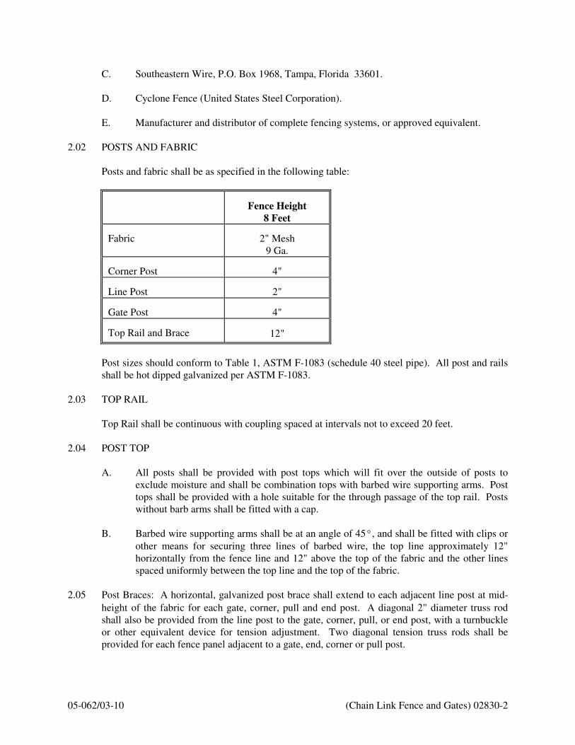
05-062/03-10 (Chain Link Fence and Gates) 02830-2
C. Southeastern Wire, P.O. Box 1968, Tampa, Florida 33601.
D. Cyclone Fence (United States Steel Corporation).
E. Manufacturer and distributor of complete fencing systems, or approved equivalent.
2.02 POSTS AND FABRIC
Posts and fabric shall be as specified in the following table:
Fence Height
8 Feet
Fabric
2" Mesh
9 Ga. Corner Post
4"
Line Post
2"
Gate Post
4"
Top Rail and Brace
12"
Post sizes should conform to Table 1, ASTM F-1083 (schedule 40 steel pipe). All post and rails
shall be hot dipped galvanized per ASTM F-1083.
2.03 TOP RAIL
Top Rail shall be continuous with coupling spaced at intervals not to exceed 20 feet.
2.04 POST TOP
A. All posts shall be provided with post tops which will fit over the outside of posts to
exclude moisture and shall be combination tops with barbed wire supporting arms. Post
tops shall be provided with a hole suitable for the through passage of the top rail. Posts
without barb arms shall be fitted with a cap.
B. Barbed wire supporting arms shall be at an angle of 45°, and shall be fitted with clips or
other means for securing three lines of barbed wire, the top line approximately 12"
horizontally from the fence line and 12" above the top of the fabric and the other lines
spaced uniformly between the top line and the top of the fabric.
2.05 Post Braces: A horizontal, galvanized post brace shall extend to each adjacent line post at mid-
height of the fabric for each gate, corner, pull and end post. A diagonal 2" diameter truss rod
shall also be provided from the line post to the gate, corner, pull, or end post, with a turnbuckle
or other equivalent device for tension adjustment. Two diagonal tension truss rods shall be
provided for each fence panel adjacent to a gate, end, corner or pull post.

05-062/03-10 (Chain Link Fence and Gates) 02830-3
2.06 Stretcher Bar: Stretcher bars 1/4" x 3/4" inch in size, with length 1" less than fabric height, shall
be provided for stretching and securing the fabric at each gate, end, corner and pull post, one for
each gate and end post and two for each corner and pull post.
2.07 Tension: Wire shall be provided along the top and bottom edges. It shall be not less than No. 7
gauge coiled spring wire. Galvanized ties or clips shall be provided for attaching tension wires
to fabric.
2.08 Wire ties shall be 9 gauge.
2.09 Barbed wire shall consists of (3) strands of 12 gauge with 4 points at 5" o.c. per ASTM A-121.
2.10 GATE
A. Frame
1. Fabricate gate frames from steel pipe to match fence framework. Assemble gate
frames by welding or with special fittings and rivets for rigid connections, that
provides security against removal or breakage connections.
2. Extend end members of gate frames 1'-0" above to member and prepare to
receive 3 strands of wire. Provide clips for securing wire to extensions.
3. Install diagonal cross-bracing consisting of 3/8" diameter adjustable length truss
rods on gates to ensure frame rigidity without sag or twist.
4. Fabricate frames of minimum 12" (NPS).
B. Fabric - Provide same fabric as for fence. Install fabric with stretcher bars at vertical
edges and at top and bottom edges. Attach stretcher bars to gate frame at not more than
15" o.c.
C. Gate Hardware: Provide hardware and accessories for each gate, in accordance with the
following:
1. Hinges: Size and material to suit gate size, non-lift-off type, offset to permit 180
degree gate opening. Provide 1-1/2 pair of hinges for each leaf.
2. Latch: Forked type or plunger-bar type to permit operation from either side of
gate, with padlock eye as integral part of latch. Center drop to be provided on
double gates.
3. Padlock: Bronze cylinder type lock with three (3) keys is to be provided for each
set of gates. Locks are to be keyed per Owner's direction.
4. Keeper: Provide keeper for vehicle gates, which automatically engages gate leaf
and holds it in open position until manually released.
05-062/03-10 (Chain Link Fence and Gates) 02830-4
2.11 FINISHES
A. Galvanized: ANSI/ASTM A 123; 2.0 oz/sq. ft.
B. Aluminum coating: ASTM A 428; 0.40 oz/sq. ft.
C. Thermally fused vinyl coating: Black color.
D. Vertical vinyl privacy slats: Black color.
E. Vinyl Components: Black color.
F. Accessories: Same finish as fabric.
PART 3 EXECUTION
3.01 INSTALLATION
A. Do not begin installation and erection before final grading is completed.
B. Work shall be performed in a safe and orderly fashion in accordance with Occupational
Safety and Health Administration (OSHA) regulations.
3.02 POST INSTALLATION
A. Excavation: Drill or hand excavate (using post hole digger) holes for posts to diameters
and spacings indicated, in firm, undisturbed or compacted soil.
1. Excavate holes for each post to minimum diameter recommended by fence
manufacturer, but not less than 4 times largest cross-section of post.
2. Excavate hole depths 3" lower than post bottom, with bottom of posts set not less
than 36" below finish grade surface.
B. Fence Post Setting
1. Line posts shall be placed equidistant at intervals not to exceed 10 ft. o.c. The
intervals to be measured parallel to the grade of proposed fence and in the line of
the fence.
2. Line, end, corner and pull posts shall be of sufficient length to allow for
installation to a depth as shown on PS-3.
3. Posts shall be set vertically and plumb and encased in cylindrical concrete
footings at least four times the post diameter, with at least a 2" cover on the
bottom of the post. Extend the concrete at least 2" above grade and crown to
shed water.

05-062/03-10 (Chain Link Fence and Gates) 02830-5
3.03 RAIL INSTALLATION
Top Rail: Connect securely to the posts using boulevard clamps or other suitable means, so that
a continuous brace is formed.
3.04 CHAIN LINK FABRIC
Chain link fence fabric shall be installed over the outside face of the fence framework. Fabric
shall be tied to line posts and middle rails with 9 gage galvanized wire spaced 12" maximum.
3.05 TENSION WIRES
Install tension wires along bottom of fence before stretching fabric and tie to each post. Fasten
fabric to tension wire using 9 gauge, wire ties or galvanized wire hog rings spaced 24" o.c.
3.06 BARBED WIRE
Pull wire taut and install to extension arms and secure to end post or terminal arms in accordance
with manufacturer's instructions.
3.07 GATES
Install gates plumb, level, and secure for full opening without interference. Install ground-set
items in concrete for anchorage. Adjust hardware for smooth operation and lubricate.
3.08 STRETCHER BARS
Thread through or clamp to fabric 4" o.c. and secure to posts with metal bands spaced 15" o.c.
3.09 BRACE ASSEMBLIES
Install braces so posts are plumb when diagonal rod is under proper tension.
END OF SECTION

05-062/03-10 (Site Restoration) 02905-1
SECTION 02905
SITE RESTORATION
PART 1 GENERAL
1.01 SCOPE OF WORK
Work included in this section consists of, but is not limited to: the restoration of pavement
(asphalt, concrete and granular), driveway, concrete curbs and gutters, sidewalks, fences, walls,
underground and above ground utilities, repair, replacement and/or relocation. Restoration of the
landscaping, i.e., shrubs, trees and grassing, is also part of this work.
1.02 QUALITY ASSURANCE
Any existing site improvements damaged during construction will be repaired at the
DEVELOPER's expense, to its existing condition to the satisfaction of OWNER and CITY OF
JEFFERSON.
PART 2 PRODUCTS
2.01 MATERIALS
Existing materials may be reused when restoring the construction site to original condition unless
those materials have been damaged or deteriorated in any way.
If material cannot be reused as determined by the CITY, it shall be replaced with new material
of like type.
PART 3 EXECUTION
3.01 GENERAL
Particular care shall be taken to minimize disturbance to existing site improvements within the
limits of construction. The DEVELOPER will take whatever measures are necessary to prevent
damage which may include, but is not limited to, erection of barriers, tree protective fencing,
shoring and bracing of excavations and staging of the construction.
3.02 CONSTRUCTION
A. No excavations will be allowed to remain open overnight and they will either be properly
backfilled or covered with steel plates to allow safe crossing of trenches by vehicles
and/or pedestrians.
B. All work must be approved by the owner and the CITY OF JEFFERSON prior to
acceptance.

05-062/03-10 (Site Restoration) 02905-2
3.03 MAINTENANCE
A. The DEVELOPER will notify the CITY to inspect restored areas as soon as construction
is complete and no further disturbances/damages would be likely to occur.
B. For work performed on Georgia D.O.T., Jackson County, and the City of Jefferson
property or Rights-of-Way, the DEVELOPER shall warrant the work free from defects
of material and workmanship for a period of one year after acceptance.
C. Clean up work areas by removing any scraps, rubbish or surplus material and dispose of
them properly off the project site.
D. Wash and hose down paved surfaces to remove all mud, debris, and other extraneous
material prior to final inspection.
3.04 GRASSING
A. DEVELOPER is to provide all information necessary for the establishment of a good
growth of grass at the time of development review submittal.
B. Information includes, but is not limited to, preparation of subsoil, placing topsoil,
fertilizing, seed type and seeding, hydroseeding, seed protection, sod laying, and
maintenance.
C. Grassing and mulching shall take place as soon as practical, but no more than 14 days,
after grading, backfilling of trench excavations, or other land disturbing activities have
ceased. In cases where grassing and mulching cannot be initiated within 14 days due to
snow cover or other adverse weather conditions, grassing and mulching shall be initiated
as soon as practical. Grassing and mulching activities do not have to be initiated on
portions of sites where land disturbing activities are temporarily stopped for less than 21
days.
D. Coverage of grassed and sodded areas shall be considered to be acceptable when all soil
disturbing activities at the site have been completed and at least 95% of the disturbed soil
surface is uniformly covered with no bare spots exceeding one square foot and the
ground surface is fully stabilized against erosion.
END OF SECTION

05-062/03-10 (Submersible Sewage Pump Station) 11310-1
SECTION 11310
SUBMERSIBLE SEWAGE PUMP STATION
PART 1 GENERAL
1.01 SCOPE OF WORK
A. The lift station shall be designed at a minimum in accordance with standards and references
set forth by the Georgia Department of Natural Resources, and in accordance with the CITY’s
minimum requirements as well.
B. For subdivisions, apartment complexes, shopping centers, and similar developments, the
CITY requires the use of submersible-type lift stations. All wastewater lift stations shall be
reviewed by the CITY and/or the Georgia Department of Natural Resources on a case-by-case
basis.
C. For the CITY’s review, the DEVELOPER shall submit Detail Sheet PS-1 completed with all
pertinent data, and documentation showing all necessary calculations for appropriate lift
station and wetwell design. The CITY may require any additional information at its
discretions in order to complete its review.
D. Each lift station design and site is unique, and shall be reviewed by the CITY as such. This
includes site layout, access, electrical requirements, appearance, controls, etc. These
standards are presented as a minimum requirement and guideline only; changes or additional
requirements to each station may be required by the CITY at their discretion as a result of
review during plan submittals and/or construction.
1.02 PUMPS
A. The CITY accepts only submersible sewage pumps: heavy duty, vertical shaft, non-clog type
passing 3-inch sphere, submersible centrifugal pumps manufactured by FLYGT.
B. The pumps furnished under this Section shall be the product of the same supplier to ensure
maximum compatibility and interchangeability of parts. The DEVELOPER-CONTRACTOR
shall assign unit responsibility to the pump supplier or manufacturer for the equipment
specified in this section in order to enhance compatibility, ease of construction, and efficient
maintenance of the components of each pumping system. The pump manufacturer shall
coordinate pump controls so that a complete and operable system is achieved.
C. Refer to Section 16000, Electrical Plans for electrical equipment requirements.
1.03 MINIMUM GENERAL REQUIREMENTS
A. All stations shall be a duplex at minimum.
B. All stations shall be designed as submersible non-clog lift station complete with access drive,
maintenance friendly layout and grading, motors, permanent discharge elbows, mix flush
valves, guide bars, intermediate, upper and lower guide bar brackets, power cables, lifting
chains, pump controls, level sensor, generator, lighting and pole, yard hydrant, anchor bolts,

05-062/03-10 (Submersible Sewage Pump Station) 11310-2
valve vault, wetwell, aluminum access hatches, fence, site work, spare parts and other
accessories including all necessary labor, supervision, materials, tools, and appurtenances.
C. Minimum wetwell diameter shall be 8-feet.
D. Wetwell shall be coated as per specification section 02603.
E. Each station shall be furnished and installed with a permanent standby generator in
accordance with specification section 16621.
F. Each lift station shall be furnished and installed with the CITY’s most current SCADA.
Contact the CITY’s sewer department for the latest requirements.
G. Check valves shall be swing type with cushion chamber and counterweight for closing speed
adjustment.
H. See lift station details for reference.
I. All phases of construction shall be inspected as per the CITY’s requirements.
J. Entire Lift Station site (50’x50’) shall be paved with concrete, access road shall be paved
concrete.
1.04 WORK INCLUDED
The DEVELOPER shall furnish and install at the locations shown on the Approved Drawings, as
specified or as directed, electrical submersible pump(s) required to complete the project.
The DEVELOPER shall be responsible for any and all details and special construction required
whether or not shown in the City’s Standards or on the Approved Drawings or called for in these
specifications. The DEVELOPER shall be responsible for the complete installation and responsibility
for the proper operation of the various components of this section. It shall also include painting, field
testing and additional services of the equipment supplier.
1.05 WORKMANSHIP AND MATERIALS
All equipment and materials furnished under this Contract shall be new, suitable for the conditions of
service to which they will be subject and equal to the best of their respective classes. Grade and
quality shall meet the applicable cited specifications and standards.
Workmanship shall be of the highest quality and shall be carried out by competent and experienced
workmen.
1.06 SUBMITTALS
Shop drawings, minimum 3 copies each, for the pumping station, associated equipment, and generator
shall be submitted to the CITY for review and comment prior to installation by the DEVELOPER.
The shop drawings must bear the stamp and approval of the design engineer prior to submitting to the
CITY. The DEVELOPER shall provide to the CITY as a minimum the submittals listed below.
Submittals shall be submitted to the CITY and approved prior to fabrication, shipment or work
specified under this section begins.
1. Manufacturer's data including materials of construction and equipment weight.
2. Predicted performance curves developed for the specific application. Performance curves

05-062/03-10 (Submersible Sewage Pump Station) 11310-3
shall plot speed, capacity, head, horsepower, efficiency, and NPSH requirements over the
manufacturer's recommended range of operation.
3. Motor submittal data.
4. Shop drawings including dimensions and cross sectional views of all equipment showing
details of construction.
5. Shop drawings including plan and sectional views of the pumps in the sump.
6. A written report on the factory test results as specified in Section 1.07 of this Specification.
7. Extended warranty as specified in Section 3.08 of this Specification.
The DEVELOPER shall also include complete working details, dimension, assembly, and installation
drawings, catalog and other data, and manufacturer's specifications and data indicating all parts,
accessories and appliances, all piping, valves, motors, conduit, wiring and equipment, methods and
material of construction, location, and installation, support, anchorage and connections and wiring
diagrams, surface finishes and other information as may be required, complete in every detail, to
define the articles to be furnished and indicate whether or not they comply with the Specifications.
A tabulated list of all motors and electrical devices shall also be furnished. Include ampere and
voltage operating characteristics for all devices. For motors, include full load amperes, power factor,
efficiencies, slop and temperature rise. Process the tabulated list, plus all special wiring diagrams as
shop drawings and as soon as possible in order to expedite the electrical work on electrical drawings.
The DEVELOPER shall also furnish under this section three (3) bound copies of complete and
detailed instructions for the operation, lubrication, and maintenance of all equipment furnished and
installed hereunder. The manuals shall be furnished after final approval of all shop and working
drawings but prior to shipment of equipment. Manuals shall be complete with wiring diagrams,
lubrication schedules and recommended lubricants, drawings, cuts, parts lists, and other necessary
data. All parts shall be numbered or otherwise clearly identified to facilitate ordering or replacements.
Descriptions of all operations control devices and their specific functions shall also be included.
1.07 FACTORY TESTS
Each pump to be delivered under this Section shall be tested for performance at the pump
manufacturer's factory to determine head versus capacity, efficiencies, and kilowatt draw required for
the operating points that are specified. All tests shall be run in accordance with the latest edition of
the American Hydraulic Institute Standards and at the appropriate voltage and frequency. Testing
shall also include, but not be limited to, the following:
Testing performed upon each pump shall include the following inspections:
1. Head vs. flow with five (5) equally spaced points including shutoff and maximum flow shall
be certified.
2 The input KW, speed, power factor, no load current, and torque characteristics shall be
certified.

05-062/03-10 (Submersible Sewage Pump Station) 11310-4
3. Impeller, motor rating and electrical connections shall first be checked for compliance to the
specifications.
4. A motor and cable insulation test for moisture content or insulation defects shall be made.
5. Prior to submergence, the pump shall be run dry to establish correct rotation and mechanical
integrity.
6. The pump shall be run for 30 minutes submerged, a minimum of 6 feet under water.
7. After the operational test described in line No. 6, the insulation test described in line No. 4
shall be performed again.
8. After testing, the pump shall be inspected to insure that the pump maintains full watertight
integrity.
A written report stating the tests have successfully been completed and providing the results of the test
shall be provided for each pump as part of the shop drawing submittal process.
PART 2 PRODUCTS
2.01 PUMP REQUIREMENTS
The pump(s) shall be heavy duty, electric submersible, centrifugal non-clog units designed for
handling raw, unscreened sewage and wastewater and shall be fully guaranteed for this use. The
pumps provided shall be capable of operating in an ambient liquid temperature of 104 DEGREES F.
Since the high temperature of 104 DEGREES F is specified by the National Electrical Manufacturers
Association (NEMA) and Factory Mutual (FM), motors with a maximum ambient temperature rating
below 104 DEGREES F shall not be acceptable.
The pump and motor unit shall be suitable for continuous operation at full nameplate load while the
motor is completely submerged, partially submerged or totally non-submerged. The use of shower
systems, secondary pumps or cooling fans to cool the motor shall not be acceptable.
The pump, mechanical seals and motor units provided under this specification shall be from the
same manufacturer in order to achieve standardization of operation, maintenance, spare parts,
manufacturer's service and warranty.
2.02 PUMP CONSTRUCTION
Major pump components shall be of grey cast iron, ASTM A-48, Class 35B, with smooth surfaces
devoid of blow holes or other irregularities. All exposed nuts or bolts shall be of stainless steel
construction. All metal surfaces coming into contact with the pumpage, other than stainless steel or
brass, shall be protected by a factory applied spray coating of acrylic dispersion zinc phosphate primer
with a polyester resin paint finish on the exterior of the pump.
Sealing design shall incorporate metal-to-metal contact between machined surfaces. Critical mating
surfaces where watertight sealing is required shall be machined and fitted with Nitrile or Viton rubber

05-062/03-10 (Submersible Sewage Pump Station) 11310-5
O-rings. Fittings will be the result of controlled compression of rubber O-rings in two planes and O-
ring contact of four sides without the requirement of a specific torque limit.
Rectangular cross sectioned gaskets requiring specific torque limits to achieve compression shall not
be considered as adequate or equal. No secondary sealing compounds, elliptical O-rings, grease or
other devices shall be used.
2.03 EQUIPMENT FEATURES
A. COOLING SYSTEM
(Cooling Jacket Equipped)
If required by FLYGT, each unit shall be provided with an integral motor cooling system. A
motor cooling jacket shall encircle the stator housing, providing for dissipation of motor heat
regardless of the type of pump installation. An impeller, integral to the cooling system and
driven by the pump shaft, shall provide the necessary circulation of the cooling liquid through
the jacket. The cooling liquid shall pass about the stator housing in the closed loop system in
turbulent flow providing for superior heat transfer. The cooling system shall have one fill port
and one drain port integral to the cooling jacket. The cooling system shall provide for
continuous pump operation in liquid or ambient temperatures of up to 104°F. (40°C.).
Operational restrictions at temperatures below 104°F are not acceptable. Fans, blowers or
auxiliary cooling systems that are mounted external to the pump motor are not acceptable.
B. CABLE ENTRY SEAL
The cable entry seal design shall preclude specific torque requirements to insure a watertight
and submersible seal. The cable entry shall consist of a single cylindrical elastomer grommet,
flanked by washers, all having a close tolerance fit against the cable outside diameter and the
entry inside diameter and compressed by the body containing a strain relief function, separate
from the function of sealing the cable. The assembly shall provide ease of changing the cable
when necessary using the same entry seal. The cable entry junction chamber and motor
shall be separated by a terminal board, which shall isolate the interior from foreign
material gaining access through the pump top. Epoxies, silicones, or other secondary
sealing systems shall not be considered acceptable.
C. MOTOR
The pump motor shall be a NEMA B design, induction type with a squirrel cage rotor, shell
type design, housed in an air filled, watertight chamber. The stator windings shall be insulated
with moisture resistant Class H insulation rated for 180°C (356°F). The stator shall be
insulated by the trickle impregnation method using Class H monomer-free polyester resin
resulting in a winding fill factor of at least 95%. The motor shall be inverter duty rated in
accordance with NEMA MG1, Part 31.The stator shall be heat-shrink fitted into the cast iron
stator housing. The use of multiple step dip and bake-type stator insulation process is not
acceptable. The use of pins, bolts, screws or other fastening devices used to locate or hold the
stator and that penetrate the stator housing are not acceptable. The motor shall be designed for
continuous duty while handling pumped media of up to 104°F. The motor shall be capable of
withstanding at least 15 evenly spaced starts per hour. The rotor bars and short circuit rings
shall be made of aluminum. Three thermal switches shall be embedded in the stator end coils,
one per phase winding, to monitor the stator temperature. These thermal switches shall be
05-062/03-10 (Submersible Sewage Pump Station) 11310-6
used in conjunction with and supplemental to external motor overload protection and shall be
connected to the motor control panel.
The junction chamber shall be sealed off from the stator housing and shall contain a terminal
board for connection of power and pilot sensor cables using threaded compression type
terminals. The use of wire nuts or crimp-type connectors is not acceptable. The motor and the
pump shall be produced by the same manufacturer.
The motor service factor (combined effect of voltage, frequency and specific gravity) shall be
1.15. The motor shall have a voltage tolerance of +/- 10%. The motor shall be designed for
continuous operation in up to a 40°C. ambient and shall have a NEMA Class B maximum
operating temperature rise of 80° C. A motor performance chart shall be provided upon
request exhibiting curves for motor torque, current, power factor, input/output kW and
efficiency. The chart shall also include data on motor starting and no-load characteristics.
The power cable shall be sized according to the NEC and ICEA standards and shall be of
sufficient length to reach the junction box without the need of any splices. The outer jacket of
the cable shall be oil resistant chlorinated polyethylene rubber. The motor and cable shall be
capable of continuous submergence underwater without loss of watertight integrity to a depth
of 65 feet or greater.
Motor horsepower shall be sufficient so that the pump is non-overloading throughout its entire
performance curve, from shut-off to run-out.
D. BEARINGS
The integral pump/motor shaft shall rotate on two bearings. The motor bearings shall be
sealed and permanently grease lubricated with high temperature grease. The upper motor
bearing shall be a single ball type bearing to handle radial loads. The lower bearing shall be a
two row angular contact ball bearing to handle the thrust and radial forces. The minimum L10
bearing life shall be 50,000 hours at any usable portion of the pump curve.
E. MECHANICAL SEALS
Each pump shall be provided with a positively driven dual, tandem mechanical shaft seal
system consisting of two seal sets, each having an independent spring. The lower primary
seal, located between the pump and seal chamber, shall contain one stationary and one
positively driven rotating corrosion resistant tungsten-carbide ring. The upper secondary seal,
located between the seal chamber and the seal inspection chamber, shall contain one
stationary and one positively driven rotating corrosion resistant tungsten-carbide seal ring All
seal rings shall be individual solid sintered rings. Each seal interface shall be held in place by
its own spring system. The seals shall not depend upon direction of rotation for sealing.
Mounting of the lower seal on the impeller hub is not acceptable. Shaft seals without
positively driven rotating members or conventional double mechanical seals containing either
a common single or double spring acting between the upper and lower seal faces are not
acceptable. The seal springs shall be isolated from the pumped media to prevent materials
from packing around them, limiting their performance.
Each pump shall be provided with a lubricant chamber for the shaft sealing system. The
lubricant chamber shall be designed to prevent overfilling and shall provide capacity for
lubricant expansion. The seal lubricant chamber shall have one drain and one inspection plug

05-062/03-10 (Submersible Sewage Pump Station) 11310-7
that are accessible from the exterior of the motor unit. The seal system shall not rely upon the
pumped media for lubrication.
The area about the exterior of the lower mechanical seal in the cast iron housing shall have
cast in an integral concentric spiral groove. This groove shall protect the seals by causing
abrasive particulate entering the seal cavity to be forced out away from the seal due to
centrifugal action.
A separate seal leakage chamber shall be provided so that any leakage that may occur past the
upper, secondary mechanical seal will be captured prior to entry into the motor stator housing.
Such seal leakage shall not contaminate the motor lower bearing. The leakage chamber shall
be equipped with a float type switch that will signal if the chamber should reach 50%
capacity.
F. PUMP SHAFT
For the NP-model pumps:
The pump and motor shaft shall be a single piece unit. The pump shaft is an extension of the
motor shaft. Shafts using mechanical couplings shall not be acceptable. The shaft shall be
stainless steel – ASTM A479 S43100-T. Shaft sleeves will not be acceptable.
For the CP-model pumps:
Pump and motor shaft shall be the same unit. The pump shaft is an extension of the motor
shaft. Couplings shall not be acceptable. The shaft shall be carbon steel ASTM A 572 and
shall be completely isolated from the pumped liquid.
G. IMPELLERS
For the NP-model pumps:
The impeller shall be of gray cast iron, ASTM A-48 Class 35B, dynamically balanced, semi-
open, multi-vane, back swept, screw-shaped, non-clog design. The impeller leading edges
shall be mechanically self-cleaned automatically upon each rotation as they pass across a
spiral groove located on the volute suction. The screw-shaped leading edges of the impeller
shall be hardened to Rc 45 and shall be capable of handling solids, fibrous materials, heavy
sludge and other matter normally found in wastewater. The screw shape of the impeller inlet
shall provide an inducing effect for the handling of up to 6% sludge and rag-laden
wastewater. The impeller to volute clearance shall be readily adjustable by the means of a
single trim screw. The Impeller shall be locked to the shaft and held by an impeller bolt.
For the CP-model pumps:
The impeller(s) shall be of gray cast iron, Class 35B, dynamically balanced, double shrouded
non-clogging design having a long throughlet without acute turns. The impeller(s) shall be
capable of handling solids, fibrous materials, heavy sludge and other matter found in
wastewater. Whenever possible, a full vaned, not vortex, impeller shall be used for maximum
05-062/03-10 (Submersible Sewage Pump Station) 11310-8
hydraulic efficiency; thus, reducing operating costs. Impeller(s) shall be keyed to the shaft,
retained with an Allen head bolt
H. VOLUTE/SUCTION COVER
For the NP-model pumps:
The pump volute shall be a single piece gray cast iron, ASTM A-48, Class 35B, non-
concentric design with smooth passages of sufficient size to pass any solids that may enter the
impeller. Minimum inlet and discharge size shall be as specified. The volute shall have a
replaceable volute insert ring containing spiral-shaped, sharp-edged groove(s). The spiral
groove(s) shall provide the relief path and sharp edge(s) across which each impeller vane
leading edge shall cross during rotation so to remain unobstructed. The internal volute bottom
shall provide effective sealing between the multi-vane semi-open impeller and the volute.
The insert ring shall be cast of (ASTM A-48 Class 35B cast iron or ASTM A 532 (Alloy lll
A), 25% chrome cast iron)
For the CP-model pumps:
Pump volute(s) shall be single-piece grey cast iron, Class 35B, non-concentric design with
smooth passages large enough to pass any solids that may enter the impeller. Minimum inlet
and discharge size shall be as specified.
I. PROTECTION
All stators shall incorporate thermal switches in series to monitor the temperature of each
phase winding. The thermal switches shall open at 125°C (260°F), stop the motor and activate
an alarm.
A leakage sensor shall be available as an option to detect water in the stator chamber. The
Float Leakage Sensor (FLS) is a small float switch used to detect the presence of water in the
stator chamber. When activated, the FLS will stop the motor and send an alarm both local
and/or remote. USE OF VOLTAGE SENSITIVE SOLID STATE SENSORS AND TRIP
TEMPERATURE ABOVE 125°C (260°F) SHALL NOT BE ALLOWED.
The thermal switches and FLS shall be connected to a Mini CAS (Control And Status)
monitoring unit. The Mini CAS shall be designed to be mounted in any control panel.
J. EXPLOSION-PROOF PUMPS:
The pump system including the pump, motor and power cable shall be approved for use in
areas classified as hazardous locations in accordance with the NEC Class I, Div. 1, Group C
and D service as determined and approved by a U.S. nationally recognized testing laboratory
(U.L., FM, CSA) at the time of the bidding of the project. As required by Factory Mutual
(FM) the motor shall be capable of operating in pumped media up to 104 DEGREES F.
Motor thermal switches shall monitor and protect the motor from excessive temperature. An
internal Float Switch shall be available, as an option, in the motor chamber. Service of
explosion-proof submersible units shall be performed by qualified FM experienced personnel.
The pump manufacturer must provide training schools to qualify personnel in the
proper service and repair of explosion proof pumps.

05-062/03-10 (Submersible Sewage Pump Station) 11310-9
K. MIX FLUSH SYSTEM:
Each pump shall be furnished and installed with the ITT Flygt mix flush valve.
L. GUIDE SYSTEM
The pumps shall be provided with a guide system to allow easy removal of the pumps without
entering the wet well. Two guide bars shall be provided extending from the top slab of the
pump station to the discharge connection of each pump and shall assist in raising and
lowering the pump unit. The discharge connection shall be bolted to the floor and shall serve
as a lower attachment for the guide bars. The working load of the lifting system shall be 50%
greater than the pump unit weight.
The pump unit shall be guided on the bars by a guide bracket which shall be an integral part
of the pump. Each pump shall be fitted with sufficient length of stainless steel chain capable
of lifting the pump and motor. The necessary fittings and eye bolts shall be provided.
PART 3 EXECUTION
3.01 INSTALLATION
The CONTRACTOR shall furnish and install the pumps at the locations shown on the Contract
Drawings and in accordance with the pump manufacturer's specification and recommendations. All
discharge elbows shall be mounted on concrete pedestals prepared for them and over anchor bolts set
in the concrete. Pump pedestals shall be carefully set at proper elevation, location and alignment, and
leveled after which they shall be properly grouted in with grout filling the entire underside of the base.
Grouting shall be as recommended by the manufacturer. All piping shall be brought to the pump
connection in such manner as to prevent the possibility of applying any loads or stresses to pump
connections.
3.02 ANCHOR BOLTS AND FASTENERS
Anchor bolts, nuts, washers, and fasteners shall be furnished with the equipment herein specified and
set in conformance with templates or drawings also supplied by the manufacturer. All anchor bolts,
studs, fasteners, washers, and nut shall be Type 316 stainless steel. The CONTRACTOR shall install
all anchor bolts, studs, washers, nuts and fasteners required to complete the work of this Contract.
3.03 SAFETY GUARDS
All exposed shafts, couplings, belts, etc., shall be provided with removable, rigidly constructed and
mounted protective safety guards, meeting in full the requirements of the OSHA standards, State
safety standards and all local codes or ordinances that my apply. Guards shall be designed to facilitate
access for lubrication, maintenance, and/or belt replacement.
05-062/03-10 (Submersible Sewage Pump Station) 11310-10
3.04 PAINTING
Unless otherwise specified, all mild steel parts not buried in concrete, cadmium plated, galvanized or
plastic covered, shall be shop primed with one coat of paint recommended as compatible with finish
coats by the manufacturer whose paint is to be used for field painting. Stainless steel, aluminum,
brass, bronze, galvanized or cadmium plated steel, and plastic covered parts will not be painted.
Machined and finished surfaces shall be protected with a suitable lubricant to prevent rusting.
The CONTRACTOR shall, under this Section, remedy all damage to shop coatings after installation of
equipment, and to the satisfaction of the ENGINEER.
3.05 TOOLS AND LUBRICANTS
The CONTRACTOR shall furnish a complete set of any special tools required for the maintenance
and operation of this equipment, as designated by the equipment manufacturer.
3.06 FIELD TEST AND START-UP SERVICE
The equipment manufacturer shall furnish the services of a qualified factory trained field service
engineer for 8-hour working day(s) at the site to inspect the installation and instruct the owner's
personnel on the operation and maintenance of the pumping units. After the pumps have been
completely installed and wired, the contractor shall have the manufacturer do the following:
a. Megger stator and power cables.
b. Check seal lubrication.
c. Check for proper rotation.
d. Check power supply voltage.
e. Measure motor operating load and no load current.
f. Check level control operation and sequence.
g. Insurance that the connection between the pump and discharge connection does not leak. If the
connection leaks, the discharge elbow shall be replaced by the pump manufacturer at no cost to
the supplying CONTRACTOR or OWNER
h. Compliance with operating conditions specified for flow rate and TDH: At least 2 draw down
tests will be conducted for each pump, and parallel pumping at each wetwell to determine average
discharge pumping rate. CONTRACTOR shall provide necessary personnel and equipment to
assist ENGINEER in measuring wetwell depths during testing. CONTRACTOR shall be solely
responsible for making all arrangements for scheduling tests, and having adequate personnel and
potable water for testing and start up.
3.07 ADJUSTING, TESTING, TRAINING AND ADDITIONAL SERVICES
In addition to the tests listed under this Section, each pump together actual motors shall be fully tested
in water at the pump manufacturers' works to establish that all rating conditions have been met. The
CONTRACTOR shall make all remedial work necessary on any or all pumps should they fail to meet
the conditions specified at no extra compensation. Pumps shall then be retested and failure to meet the
specified conditions after remedial work has been performed may be cause for rejection of the pumps.
On completion of the work, the entire pumping equipment shall be lined up, operated and adjusted by

05-062/03-10 (Submersible Sewage Pump Station) 11310-11
qualified representatives of the several pump and control manufacturers, and under the intended
operating conditions, and shall be left in first class, satisfactory, operating conditions, ready for
continuous and satisfactory operation. The CONTRACTOR shall furnish all power, oil, fuses and
other supplies for the field testing of the pumps, equipment, controls, and appurtenances, together with
the services of the manufacturer's representatives.
3.08 PUMP WARRANTY
The pump manufacturer shall submit the proper documentation demonstrating that the pump
manufacturer warrants the pumps being supplied to the OWNER against defects in materials and
workmanship for a period of five (5) years or 10,000 hours under a Municipal Wastewater Permanent
Installation Warranty.
END OF SECTION

05-062/03-10 (Lift Station Electrical Work) 16000-1
SECTION 16000
LIFT STATION ELECTRICAL WORK
PART 1 GENERAL
1.01 SCOPE OF WORK
WORK described in this section shall consist of furnishing, installing, and connecting all panels,
motor control center, lighting fixtures, and all other equipment shown or otherwise indicated in
the DEVELOPMENT DRAWINGS. This section shall provide minimum, general guidelines
and requirements; all and any electrical plans shall be designed by a qualified, registered
electrical engineer in the state of Georgia.
1.02 CODES AND STANDARDS
A. WORK performed under this section shall conform to the latest edition of the National
Electrical Code.
B. Equipment and material furnished under this section shall be new, unused, and shall be
manufactured to the following standards:
1. I.E.E.E. - Institute of Electrical & Electronic Engineers.
2. A.N.S.I. - American National Standards Institute.
3. U.L. - Underwriters Laboratories, Inc.
4. I.C.E.A. - Insulated Conductor Engineers Association.
1.03 POWER SERVICE
A. In general the power service to the pump stations shall be three phase as listed below in
the preferred order:
1. 480/277V, 3 phase, 4 wire, Wye connected
2. 120/208V, 3 phase, 4 wire, Wye connected
3. 120/240V, 3 phase, 4 wire, Delta connected
4. 480V, 3 phase, 3 wire open Delta connected (contact the power company for
motor horsepower limitation)
5. 120/240V; 3 phase, 4 wire, open Delta connected (contact the power company
for motor horsepower limitation)
B. For pump stations with motors 10Hp and smaller, single phase power service may be
provided with written approval from the City.

05-062/03-10 (Lift Station Electrical Work) 16000-2
A letter from the power company state that three phase power is not available at the
location must be submitted to the City with the request.
If the City approves the request for single phase power service, variable frequency drives
shall be used in the pump control panel for the ump motors. The variable frequency
drives shall have single phase input and three phase output. The pump motors shall be
three phase.
C. Use of phase converters and single phase pump motors will not be permitted.
PART 2 PRODUCTS
2.01 STATION APPURTENANES
A. A main circuit breaker shall be provided in the pump station and shall be located inside
the fenced area of the station. The circuit breaker shall meet the following requirements:
1. U.L. listed for service entrance.
2. In NEMA-4X stainless steel enclosure.
3. Capable of being padlocked in both “on” and “off” positions.
B. Underground conduits shall be scheduled 40 PVC. All exposed conduits shall be rigid
galvanized steel.
C. No conduit runs or junction boxes shall be installed inside or on top of the wet well.
Splicing of cables inside the wet well will not be permitted.
D. The power, lighting and control cables shall be copper conductors with 600V type
‘XHHW’ insulation, #12 AWG minimum size. The signal cables shall be copper
conductors, 600V rated, twisted and shielded type, #16 AWG minimum size.
E. A surge suppressor shall be provided at the power service entrance. The surge suppressor
shall have voltage characteristics to match the power service.
The surge suppressor shall be in NEMA-4X stainless steel enclosure and shall provide
line to lien, line to neutral, line to ground and neutral to ground protection modes as
applicable for the power service.
The surge suppressor shall be provided with a disconnect. Minimum surge current rating
shall be 100KA per mode, 200KA per phase per NEMA LS-1. The surge suppression
system shall be duty cycle tested to survive 20KV, 10KA, IEEE C62.41 category surge
current with less than 5% degradation of clamping voltage.
The surge suppressor shal have minimum repetitive surge capacity of 4500 impulses per
mode. Status indicating lights and form ‘C’ dry alarm contacts shall be provided.
The surge suppressor shall be U.L. listed and labled under UL1449 and UL1283.
Acceptable manufactures are Liebert and Current Technology.

05-062/03-10 (Lift Station Electrical Work) 16000-3
F. A mini-power center shall be provided in the pump station when the power service is 480
volts. The mini-power center shall be in an outdoor weatherproof enclosure which shall
consist of a transformer with primary and secondary circuit breakers and a 120/240V
panel board. The panel board shall have at least two spare branch circuit breakers.
G. The electrical equipment shall be mounted on an adequately sized galvanized steel or
aluminum structure. Telemetry RTU shall also be installed on this structure. Large pump
control panels shall be installed on concrete pad.
H. A ground fault circuit interrupter type outlet in weatherproof enclosure shall be provided
on the mounting structure fro the City’s use.
I. A ground grid consisting of a minimum four ¾” diameter, 10’ long copperweld rods at
the corners of the fenced area connected with minimum #2 AWG bare stranded copper
conductor run underground around the perimeter shall be provided. All the grounding
connections shall be exothermic type. Mechanical connection are not permitted. The
main circuit breaker, generator and the pump station fence shall be grounded to the
ground grid.
J. Each site shall have an exterior hinged light pole with 250 watt metal halide luminaire,
120 volt ballast, photoelectric control, with heat and impact resistant lens. Pole is to be
architectural brown and is to be supplied with lowering winch.
BRACKET: G.E. PART # RBSU2H6PP
POLE: G.E. PART # ASHTS202T-5.3-11PP
2.02 TELEMETRY SYSTEM
A. The system shall be Model Mission M800 as manufactured by Mission
Communications, LLC to match City of Jefferson’s existing installations. The
DEVELOPER shall pay upfront for three (3) years of monitoring service and
provide proof of payment to the City Sewer Department prior to acceptance of the
system.
B. The monitoring RTU shall be enclosed in a NEMA 4X enclosure equipped with
sun shield. The RTU shall transmit all data and alarms via the Nextel or Sprint
wireless data network. Such network(s) shall have 128-bit AES encryption. The
RTU shall be powered by 120 volts AC and have a built in battery backup capable
of keeping the RTU powered for 24 hours in case of primary AC failure. All
terminations inside the RTU enclosure shall be low voltage AC or DC (28 volts or
less). The RTU shall be supplied with a U.L. recognized 120 VAC to 12 VAC
step down transformer. The RTU shall have two (2) analog, 10-bit resolution, 4-
20mA or 0-5 VDC inputs, with four (4) alarm thresholds per input. The analog
input values shall be transmitted by the RTU to the central monitoring software at
least every 2 minutes. The RTU shall have built in AC failure and low battery
detection. The RTU shall have sixteen (16) digital inputs of which up to three (3)
shall be capable of recording pump runtimes in one (1) minute resolution. Any
change of the RTU digital inputs shall be transmitted to the central monitoring

05-062/03-10 (Lift Station Electrical Work) 16000-4
software within 10 seconds of occurrence. The RTU shall have at least three (3)
remotely controllable relay outputs that may be controlled at will by the customer.
C. The following remote input contacts shall be connected to the RTU:
• Wetwell low level
• Wetwell high level
• Pump #1 run
• Pump #2 run
• Pump(s) fail
• Phase loss
• Surge suppressor failure (via form C dry contact in suppressor)
• Generator transfer
• Generator Common Alarm (low fuel, low oil, fail start)
• Level Sensor
D. The RTU shall have up to two (2) optional pulse counting totalizers of which one
can be programmed to report every two (2) minutes. The RTU shall have a built
in electronic key or card reader, which can be used to securely put the RTU in/out
of alarm reporting mode and/or to accept in progress alarms. The RTU shall be a
Mission model 800.
E. The RTU shall be capable of reporting alarms and all supervisory information to a
password protected customer web site, an OPC compliant customer HMI software
package or both. The web site or HMI software package shall be capable of
displaying all RTU alarms and supervisory data. This shall include alarms,
individuals accepting alarms, RTU electronic key/card reads with user names and
time of read, pump running status, pump run times with historical graphs,
individual pump flow estimates, automatic daily analysis of pump runtimes for
abnormalities with automatic customer notification of such abnormalities, pump
starts, hourly analysis of excess pump starts with automatic notifications of excess
pump starts, minute-by-minute radio health checks with automatic notification of
non-reporting or poorly reporting RTU's, scaled and labeled pulse totalizations
and if rainfall gauges are used, inter-day rainfall graphs. The customer web site or
HMI software package shall be capable of performing and displaying volumetric
inflow calculations from RTU supplied data for each pump cycle as they occur.
Such volumetric calculations will utilize real-time pump start/stop data with
simultaneously gathered level transducer data to perform the inflow and pump
GPM calculations. The customer web site or HMI software package shall be
capable of reporting alarms via phone dialup, numeric pager dialup, alpha numeric
pager, fax or email or any combination of the above. The customer web site or
HMI software shall produce an audit report of every alarm or notification event
with accurate results of all notification attempts. The customer web site or HMI
software shall produce and deliver weekly reports which summarize alarms and

05-062/03-10 (Lift Station Electrical Work) 16000-5
responses, pump runtimes and flow estimates and all electronic key or card uses at
the RTU sites.
F. The RTU Supplier shall provide services of factory trained technician to check,
start-up, instruct Owner's personnel and put in operation the telemetry system. A
certificate of successful commissioning of the system shall be provided to the
CITY.
2.03 PUMP CONTROL PANEL
A. Pump control panel enclosure shall be NEMA-4X stainless steel with a hinged
front door and an inner swing door. Selector switches, indicating lights, elapsed
time meters, etc. shall be mounted on the inner swing door.
B. Circuit breakers shall be thermal-magnetic with adequate short circuit ratings.
Motor circuit protector type circuit breakers may be used for motors.
C. Motor starters shall be full voltage non reversing or solid state reduced voltage
type as required by design. The minimum starter size shall be NEMA size 1. The
solid state reduced voltage starters shall be provided with an integral bypass
contactors and either an isolation contactor on the line side or a breaker with shunt
trip.
D. Six digit elapsed time meter shall be provided for each pump.
E. Control power transformers shall be provided to obtain 120V and 24V control
power as required.
F. A phase monitor shall be provided to monitor low voltage, phase loss and phase
reversal.
G. A weatherproof, shatterproof red alarm light fixture shall be provided on panel top
to indicate alarm conditions.
H. The pump level control system shall consist of Flygt catalog #FMC200 controller
and Flygt catalog #LS-100 level sensor. A spare level sensor shall be provided for
each pump station. A high level float shall be provided as a backup to the level
sensor.
I. The following alarm/status contacts shall be provided for connection to the
Telemetry RTU:
• Wetwell Low Level
• Wetwell High Level
• Pump #1 Run

05-062/03-10 (Lift Station Electrical Work) 16000-6
• Pump #2 Run
• Pump(s) Fail
• Phase Loss
• Surge suppressor failure (via form C dry contact in suppressor)
• Generator transfer
• Generator Common Alarm (low fuel, low oil, fail start)
• Level Sensor
J. A final As-Built drawing encapsulated in mylar shall be provided and kept in the
inside of the front door.
K. The panels shall be fabricated in UL-508 approved facility and shall bear U.L.
label.
L. The panels shall be factory tested and certified by the Panel Fabricator. The
panels shall be guaranteed for minimum of one year from the date of acceptance
by the City of Jefferson.
PART 3 EXECUTION
3.01 GUARANTEES AND TESTS
A. WORK shall be guaranteed for 12 months after date of acceptance. WORK shall be free
from improper grounds and short circuits.
B. DEVELOPER is required to test new pump stations with generator prior to acceptance of
the facility with manufacturer’s representatives.
END OF SECTION

05-062/03-10 (Standby Power Generator) 16621-1
SECTION 16621
STANDBY POWER GENERATOR
PART 1 GENERAL
1.01 SCOPE OF WORK
A. WORK described in this section shall consist of furnishing a portable standby power
generator.
B. DEVELOPER shall furnish all material and labor to perform the work.
1.02 CODES AND STANDARDS
A. WORK performed under this section shall conform to the latest edition of the National
Electrical Code.
B. Equipment and material furnished under this section shall be new, unused, and shall be
manufactured to the following standards:
1. I.E.E.E. - Institute of Electrical and Electronic Engineers
2. A.N.S.I. - American National Standards Institute
3. U.L. - Underwriters Laboratories, Inc.
4. I.C.E.A. - Insulated Conductor Engineers Association
PART 2 PRODUCTS
2.01 STANDBY GENERATOR
A. The standby generator shall be rated for continuous standby service for the full load demand
of the station. This shall include running both pumps with staggered startups.
B. The generator shall be housed in a weatherproof enclosure. Quiet site soundproofing shall be
provided to reduce noise to the following levels at a distance of 7 meters:
• 60dB for Natural Gas Generators
• 68dB for Diesel Generators up to 80KW
• 74dB for Diesel Generators above 80KW
C. The entire standby generator set shall have a manufacturer’s warranty for a minimum period
of five (5) years from the date of acceptance.

05-062/03-10 (Standby Power Generator) 16621-2
D. Outdoor weather-protective housing with critical grade exhaust muffler shall be installed.
The housing shall have hinged side access doors and a rear control door. All doors shall be
lockable. All sheet metal shall be primed for corrosion protection and finish painted with the
manufacturer’s standard color. Vibration isolators as recommended by the generator set
manufacturer shall be provided. The generator must be mounted far enough away from
obstructions to allow all doors to be opened 90°. All conduits and gas lines shall be installed
underground.
E. Generator shall be supplied with all auxiliary systems necessary for operation such as
batteries, battery charger, block heater, etc.
F. The standby power system shall include an automatic transfer switch. Transfer switch shall
be rated for 100% of full load of the main disconnect switch.. Switch shall be provided with
indicators for all phases of operation and be equipped with a fully programmable timer for
exercising the equipment. The switch must be selectable for load or no load.
G. Three complete sets of O & M manuals and keys shall be provided for generator and
automatic transfer switch.
H. Generator control system must include a programmable control device to allow automatic
start-up and test functions. Test functions can be programmed for daily, weekly or monthly
testing. Connections for remote monitoring of function and failure must be provided.
I. Pump stations are required to have continuous standby power. Generators rated 100 KW and
below shall be installed to operate on natural gas. All gas piping and connecting equipment
shall be installed in accordance with the Georgia State Amendments to the Standard Gas
Code, latest edition. All gas supply lines must include a drip loop as well as all other
equipment required for a safe and complete hook-up.
If gas is unavailable, a letter of exception must be obtained from the City. Generators above
100 KW shall be diesel powered with 100 gallons minimum fuel storage capacity or 24-hour
operating time, which ever is greater. Fuel storage shall be accomplished by the use of
corrosion –resistant double wall sub-base fuel tank only, no underground storage will be
allowed. A leak detection device shall be provided in the interstitial space for sensing fuel
leakage. The device contact shall be connected to the generator control panel terminals for
telemetry.
J. Generators can be obtained from the following manufacturers/representatives:
a. Cummins-Onan
K. Transfer switches shall be in NEMA-4 enclosures obtained from the manufacturer of the
generator.
PART 3 EXECUTION

05-062/03-10 (Standby Power Generator) 16621-3
3.01 TESTING
A. Services of manufacturer's authorized representative shall be provided for supervision of the
installation, check-out and start-up.
B. Generator shall be load tested at 100% full load on site for a period of four hours using
resistive load banks. Notify the City inspector prior to test, and provide certification letter
from the manufacturer.
C. Upon completion of the check-out and testing, the manufacturer's representative shall provide
written certification that the system has been properly installed, tested and is functioning
properly.
3.02 INSTRUCTIONS
Provide after the successful testing one "Instructions and Training Session" with the Owner's
designated personnel. Give instructions on operation, function and maintenance.
Provide three (3) sets of complete Operation and Maintenance Manuals and Keys.
3.03 SYSTEM SERVICE CONTRACT
Provide for Owner's consideration a copy of the manufacturer's standard service contract after the
successful start-up.
END OF SECTION