deterministic generation of multidimensional photonic
TRANSCRIPT

Deterministic generation of multidimensional photonic cluster states using time-delayfeedback
Yu Shi1, ∗ and Edo Waks1, 2, 3, †
1Department of Electrical and Computer Engineering and Institute for Research in Electronics and Applied Physics,University of Maryland, College Park, Maryland 20742, USA
2Joint Quantum Institute, University of Maryland, College Park, Maryland 20742, USA3Department of Physics, University of Maryland, College Park, Maryland 20742, USA
(Dated: July 8, 2021)
Cluster states are useful in many quantum information processing applications. In particular,universal measurement-based quantum computation (MBQC) utilizes 2D cluster states [1], andtopologically fault-tolerant MBQC requires cluster states with three or higher dimensions [2]. Thiswork proposes a protocol to deterministically generate multi-dimensional photonic cluster statesusing a single atom-cavity system and time-delay feedback. The dimensionality of the cluster stateincreases linearly with the number of time-delay feedback. We firstly give a diagrammatic derivationof the tensor network states, which is valuable in simulating matrix product states (MPS) and pro-jected entangled pair states (PEPS) generated from sequential photons. Our method also providesa simple way to bridge and analyze the experimental imperfections and the logical errors of thegenerated states. In this method, we analyze the generated cluster states under realistic experi-mental conditions and address both one-qubit and two-qubit errors. Through numerical simulation,we observe an optimal atom-cavity cooperativity for the fidelity of the generated states, which issurprising given the prevailing assumption that higher cooperativity systems are inherently betterfor photonic applications.
I. INTRODUCTION
Cluster states are highly entangled multi-qubit statesthat play a significant role in quantum communicationand quantum computation [3]. They provide entangle-ment resources for multi-qubit quantum teleportationand super-dense coding [4, 5], in addition to applica-tions in quantum error correction [6, 7] and quantummetrology [8, 9]. Cluster states also enable universalmeasurement-based quantum computation [1, 10]. How-ever, only cluster states of two dimensions or higher carrysuch universality, and topologically fault-tolerant clusterstate quantum computation requires at least three di-mensions [2]. Therefore, there is a need to develop newmethods to generate multi-dimensional cluster states [11–16].
Among various quantum platforms, photons are con-sidered ideal candidates for implementing cluster statesbecause of their pristine coherence properties and pre-cise single-qubit control. One method to obtain a scal-able 1D cluster state is by generating entangled photonsfrom a quantum emitter [17, 18]. However, the extensionof this approach to higher dimensions requires entangledquantum emitters, which is significantly more challeng-ing [14, 19]. Recently, Pichler and colleagues proposed analternative approach to achieve 2D cluster states by feed-ing back the generated photons to the quantum emitter[12]. However, expanding this method to three dimen-sions or higher, which is essential for fault tolerance [2],remains unsolved.
∗ [email protected]† [email protected]
We propose a protocol to generate higher-dimensionalphotonic cluster states using a single cavity-coupled atomcombined with time-delay feedback. We exploit the atomas an ancilla that applies sequential quantum gates onphotons and effectively entangles them. By looping pho-tons back to the cavity multiple times, we can extend thecluster state’s dimensionality to an arbitrary size. Fur-thermore, we firstly give a diagrammatic derivation of thetensor network states, which is valuable in simulating ma-trix product states (MPS) and projected entangled pairstates (PEPS) generated from sequential photons. Ourmethod also provides a simple way to bridge and analyzethe experimental imperfections and the logical errors ofthe generated states. In this method, we analyze thegenerated three-dimensional cluster states under realis-tic experimental conditions and address both one-qubitand two-qubit errors. We observe a surprising behaviorin the fidelity of generated states versus the atom-cavitycooperativity. It also shows that our approach can gener-ate cluster states with nearly unity fidelity using a chiralcoupling atom-cavity system.
II. PROTOCOL
We first consider how to generate 3D cluster statesand then generalize to higher dimensions. A 3D clusterstate can be defined on a 3D lattice, in which the nodesrepresent qubits (i.e., photons in this case), and the edgesrepresent the entanglement between photons. Figure 1ashows a cluster state on a cuboid lattice with dimensionsof N×M×L. We can give each photon inside the lattice aunique coordinate (n,m, l) in terms of its row (n), column(m), and layer (l) position, and label it (k) using the
arX
iv:2
101.
0777
2v2
[qu
ant-
ph]
6 J
ul 2
021

2
! !"#$%&
" %'(&
#)'!*+,&
$%&%&%'
!"#
$"&#&!'
!
!"$#
!"%
(a)
! " #$%& #$& #$! #
(b)
FIG. 1. (a) The schematic of a 3D cluster state on a cuboidlattice with dimensions N × M × L. Each node representsa photon, while the edges between nodes represent entangle-ment. The entanglement of photon k with its nearest neigh-bors k− 1, k−N , and k−MN define the system’s unit cell.(b) By rearranging the 3D lattice into a linear chain, photonk of the unit cell is entangled with one nearest neighbor pho-ton k − 1, and two non-nearest neighbor photons k −N andk −MN .
following formula:
k = (l − 1)MN + (m− 1)N + n .
Based on this system, the entanglement of photon k withits nearest neighbors, k−1, k−N , and k−MN , describesthe unit cell of the 3D lattice.
Photons are flying qubits, therefore a fixed 3D latticestructure is not convenient for generating a photon-based3D cluster state. As an alternative, we can rearrange thelattice as a linear chain. To form a linear chain fromthe 3D lattice, we list the photons sequentially by theirlabel k (Figure 1b). The photons then feature a com-bination of both nearest and non-nearest neighbor en-tanglement within the chain. For example, as Figure 1bshows, photon k of the unit cell is entangled with onenearest neighbor photon k − 1, but now photons k − Nand k −MN correspond to two non-nearest neighbors.However, generating this entanglement between nearestand non-nearest neighbors in the linear photon sequenceis a challenge, particularly given that photons cannot di-rectly interact with each other.
One way to generate nearest-neighbor entanglementbetween photons is through sequential interactions withan ancilla (i.e. an atomic qubit). Figure 2a shows how
an ancilla can generate a 1D cluster between a sequenceof periodically spaced photons with an equal delay timeTcycle (one clock cycle). The photons, represented byblue circles, propagate from right to left and are suffi-ciently separated to ensure they interact with the ancillaindividually and sequentially. We initialize each photonto the state |+〉 = 1√
2(|0〉+ |1〉), where |0〉 and |1〉 are the
computational basis. We assume that the ancilla appliesa controlled phase flip (CPHASE) gate to each photon,which entangles the photon with the ancilla (later wewill describe a specific way to implement this gate usinga single atom-cavity system). We then follow this processwith Hadamard gates, as shown in Figure 2b. When theCPHASE and Hadamard gates are applied sequentiallyin this manner to photons k and k + 1, they generatean effective CPHASE gate between the two photons (seeAppendix A). By iterating this process for each cycle ofthe experiment for all photons in the linear sequence, wecan generate a 1D cluster state, as previously shown byLindner and Rudolph [17].
Generating non-nearest neighbor entanglement be-tween photons requires time-delay feedback. Figures 2cand 2d show how to implement interaction between twophotons k and k−N . A mirror reflects photon k−N backto the ancilla with a delay NTcycle. The ancilla subse-quently applies a CPHASE gate to photon k−N and thenphoton k. After this, a Hadamard gate on photon k andthe ancilla effectively swap their states, which generatesthe non-nearest neighbor entanglement between photonsk and k −N and prepares the system for the next clockcycle (see Appendix A). Applying this to all photons inthe chain generates a 2D cluster state.
!"#$%%&
!"#$"# %&$"#
' '()
!"#$#%&'!"#
!"#!"#$#%&(
!"#!"#$#%&)
*%+,--. !"# !
!
!
!
!
!
!"##$#
!
!"#
%&'"(()
$%&'(
)'(&'(
!"*
!"#$%%&
'()*)"+,-.
'()*)"+,
!
!!"#
(a) (c)
(b)(d)
FIG. 2. (a) The schematic diagram shows a system involv-ing a stationary ancilla and a sequence of photons. Photonsinteract with the ancilla one at a time inside the box, corre-sponding to each process cycle. (b) The quantum circuit forgenerating nearest neighbor entanglement between photons.The vertical lines stand for CPHASE gates, and the squareslabeled H stand for Hadamard gates. (c) The schematic di-agram for generating non-nearest neighbor entanglement in-volving a stationary ancilla, a sequence of photons, and onetime-delay photon feedback. In an actual experiment, pho-tons k − N and k are separated in time and sequentially in-teract with the ancilla during one cycle. (d) The quantumcircuit for entangling photons k −N and k.

3
!"#"# $!"%
!&#'# $%
! "#$%
"&#'()*%
!"##$#%&
'
'()
*+,"--.
'(!)
!"##$#%/
012312
'(& 4+312
!"#$%%&
'()*)"+,-./
'()*)"+,-/
'()*)"+,
!
!!"#
!
"!#
!"#$%%&
"!#!
!!$
'()*()
+"*()
"!#"#$
(a) (b)
(c) (d)
FIG. 3. (a) The diagram for generating 3D cluster statesinvolving a stationary ancilla, a sequence of injected photons,and two time-delay feedbacks. In an actual experiment, pho-tons k −MN , k − N , and k are separated in time and se-quentially interact with the ancilla during one cycle. (b) Thequantum circuit for entangling photons k−MN , k−N , andk. (c) An example of the helical entanglement of a 3D clus-ter state, where boundary photons (N,M, l) and (1, 1, l + 1)are entangled. (d) The schematic diagram for generating d-dimensional cluster states using (d− 1) time-delay feedbacks.
Now that we have a way to generate both nearestand non-nearest neighbor interactions, we can combinethem to form multi-dimensional cluster states. Fig-ure 3a shows how to do this for the case of a 3D clusterstate, which requires two non-nearest neighbor interac-tions, therefore two time-delay feedbacks. The first mir-ror delays a photon for NTcycle and the second delaysfor (MN −N)Tcycle, which allows the ancilla to applya CPHASE gate to photons k −MN , k − N , and k se-quentially. The protocol is actually agnostic to the orderwith which the CPHASE gates are applied, but we as-sume this particular order for concreteness. After theCPHASE gates, we apply a Hadamard gate on photonk and the ancilla, which realizes the quantum circuit inFigure 3b. Iterating this circuit sequentially over eachcycle for all the photons yields a 3D cluster state.
The procedure outlined above generates a cluster statethat is slightly different from the one illustrated in Fig-ure 1a. The interior of the cluster state is identical, butthe edge produces a more complicated boundary condi-tion as shown in Figure 3c. Photon (N,M, l), which ison the lattice boundary, is also entangled with photon(1, 1, l + 1), because these two photons are next to eachother in the rearranged linear chain. Therefore, the re-sulting cluster state features helical connectivity, as wasthe case for the 2D cluster state proposed by Pichler etal. [12], but now extended to a higher dimension. Notealso that the elementary cell in the fault-tolerant clusterstates is not a primitive cubic as shown in Figure 1a [2],but we can obtain it by measuring and eliminating theextra qubits after the generation process.
The extension to even higher dimensions follows anal-ogously. Each dimension requires an additional non-nearest neighbor connection, which necessitates anothertime-delay feedback. As illustrated in Figure 3d for gen-erating d-dimensional cluster states, we use (d− 1) mir-rors to implement (d − 1) time-delay feedbacks. There-fore, the protocol is efficient in the sense that increasingthe dimensions results in only a linear increase in thenumber of time-delay feedback.
III. PHYSICAL IMPLEMENTATION
The previous section provides an abstract outline of theprotocol of generating multi-dimensional cluster states.Here we describe a method to implement this conceptbased on photonics and cavity quantum electrodynam-ics. We consider the specific case where the ancilla iscomposed of an atomic spin qubit coupled to an opti-cal single-sided cavity, as illustrated in Figure 4a. Thesesystems are already known to generate CPHASE gatesbetween the atomic and photonic qubits using cavity-mediated interactions, as proposed theoretically [20] andrealized experimentally using numerous atomic systems,including quantum dots [21–24], atoms [25, 26], and colorcenters in diamond [27].
We consider an atom in a cavity where an externalmagnetic field is applied in a direction parallel to itscross-plane. Figure 4b illustrates this specific atomic-level structure. The atomic spin qubit possesses twoground states (|↑〉 , |↓〉) and two excited states (|⇑〉 , |⇓〉),where the quantization axis is along the direction of themagnetic field. The atom features four optical transi-tions. The vertical transitions couple to a linearly polar-ized photon whose polarization is parallel to the quan-tization axis; the cross transitions couple to a linearlypolarized photon whose polarization is perpendicular tothe quantization axis [28]. We assume the cavity onlysupports one linearly polarized mode that enables thevertical transitions. We define this polarization direction
!"#$"%&"'()*+&+,
-,).&()*+&+,
/0,1$"230'"(%450&6
7&+80%(9.:0&
!
"
#
$
! !"
(a)(b)
FIG. 4. (a) The schematic implementation of the CPHASEgate achieved by reflecting a photon from the single-side cav-ity containing an atomic qubit coupled single-side cavity. (b)The atomic-level structure of the cavity-coupled atomic qubit,which features four optical transitions. V(H) means the ver-tical(horizontal) polarization of light.

4
as the vertical (V) polarization and its orthogonal direc-tion as the horizontal (H).
When the probe beam (external photon) is in the hori-zontal polarization, it will reflect off a mirror and acquireno phase shift. When the probe beam is in the verti-cal polarization, the reflection coefficient of the cavity isgiven by [29] (see Appendix B)
r↑,↓ =g2 − γ
2
[i∆↑,↓ + κ
2
]g2 + γ
2
[i∆↑,↓ + κ
2
] , (1)
where ∆↑,↓ is the frequency detuning between the photonand atomic transition; g, κ, and γ are the atom-cavitycoupling strength, atom dipole decay rate, and cavitydecay rate, respectively. We assume the spin-up tran-sition is on-resonant with the frequency of the photon(∆↑ = 0), therefore the spin-down transition frequencydetunes ∆↓ from the photon frequency by the Zeemansplitting. When the spin is in state |↑〉, the reflection
coefficient r↑ =C↑−1C↑+1 where we define C↑ = 4g2
γκ as the
on-resonant atom-cavity cooperativity. When the spin is
in state |↓〉, the reflection coefficient r↓ =C↓−1C↓+1 where we
define C↓ = 4g2
γ(κ+i2∆↓)as the off-resonant cooperativity.
In the limit of high on-resonant cooperativity (C↑ � 1)
and large detuning(
∆↓ � κC↑2
), the two reflection co-
efficients approach r↑ = 1 and r↓ = −1, repectively. Wedefine the state of the incident photon as |H〉 ≡ |0〉pfor a horizontally polarized photon and |V 〉 ≡ |1〉p for avertically polarized photon. We similarly label the spinstates as |↑〉 ≡ |0〉A and |↓〉 ≡ |1〉A. The state of the to-tal system, denoted as |ψ〉 = |x〉p ⊗ |y〉A where x and yare the qubit states of the photon and spin respectively,transforms according to the following operator
URF =
1 0 0 00 1 0 00 0 r↑ 00 0 0 r↓
. (2)
The reflection of the photon from the cavity applies aCPHASE gate between the photon and atomic qubit.
Figure 5a shows how we can physically implement thetime-delay feedback required to generate a 3D clusterstate. The two time-delay feedback loops consist of twodelay lines (delay line 1 and 2) and two fast opticalswitches (switch 1 and 2) that can be rapidly changedto either reflect or transmit photons. We insert a λ
4 -waveplate into delay line 2 to rotate the polarization ofthe photons. We also insert a switch in the input/outputport of the system to direct the input photons toward thecavity and couple the photons leaving the cavity with theoutput port. We denote the time delay between sequen-tially injected photons as Tcycle. To generate a 3D clusterstate with a dimension of N ×M × L, we set the delayof line 1 as
(MN −N − 1
3
)Tcycle and that of line 2 as(
N − 13
)Tcycle. We define the time delay between switch
1 and the cavity as τ1, the delay between switch 1 andswitch 2 as τ2, in which τ1, τ2 � Tcycle.
!"#$%&'(")&*+,-"./
0.12"+*345".
! "'64%(&
7&%,/*!! 7&%,/*!"!8".+9*:
7&%,/*;"5&<*:
=91.1#*#$%&
>"<<1< >"<<1<
!8".+9*?
#$'8,-&6%,.&
7&%,/*;"5&<*?
=91.1#*#$&
@4.
=91.1#*'
A#
!8".+9
! "!"!#$"!"!#$#
$"!"!#$#
!"#$%$&'(&)'*+(,
%!&' %!' %%&-."#$%
!!"!#$
!"#$%&'(
)*+,*%$#-.
/01.23#22#-.
!"%"& !"% "& !"%
!!"!#$#
$!!"!#$#
%
"##$%&!
"##$%&" "##$%&#
"##$%&$
"##$%&% "##$%&&
&!'( &!( &
!"#$%&'(
!!"!#$
)*+,*%$#-.
/01.23#22#-.!"%""& !"%"!"&
!!"!#$#
$!!"!#$#
%
#$$%&'!
#$$%&'"
#$$%&'#
#$$%&'$%
&!'( &!( &
(a)
(b)
(c)
FIG. 5. (a) The physical setup for generating a 3D clusterstate. At the kth cycle, photons k −MN , k − N , and k se-quentially reflect off the cavity. (b) Schematic diagrams show-ing how the two switchable mirrors flip their states betweenreflective and transmissive during a photon injection period(Tcycle). The arrows indicate the time points when photonsreach the switches. (c) A diagram showing the sequence ofpulses reaching the cavity during Tcycle.
Figure 5b shows how we set the reflection and trans-mission states of switch 1 and switch 2 as a functionof time relative to the beginning of the kth cycle, de-noted as t = 0. We divide the clock cycle Tcycle intothree sections corresponding to the propagating periodsof photons k − MN , k − N , and k, respectively. Thearrows denote the timings when a photon arrives at eachswitch, either in the forward direction to the cavity orin the backward direction after reflecting from the cav-ity. The timings are selected such that photon k −MNfirst interacts with the cavity and leaves the system, thenphoton k − N reflects off of the cavity and is injectedinto delay line 1, then photon k reflects off of the cav-ity and is injected into delay line 2. These steps im-plement the CPHASE gates between the photons andthe ancilla shown in the quantum circuit in Figure 3b.

5
Then, in delay line 2, photon k passes through the λ4 -
waveplate, reflects off a mirror and passes through thewaveplate again, which realizes an effective π
2 rotation,thus performing a Hadamard gate on the photon polar-ization [30]. Finally, we perform a Hadamard gate onthe atomic qubit using an ultrafast optical Raman con-trol pulse of π
2 rotation [28, 31], as shown in the timingdiagram in Figure 5c, in which the π
2 -pulse arrives at thecavity after the sequential reflections of photons k−MN ,k −N , and k in the cycle.
For the first few photons 1 through MN , either delayline 1 or delay line 2 may not contain any photons. How-ever, the procedure still works and does not need to bemodified in this initial phase. For photons 1 through N ,both delay lines are empty, so these photons will reflectoff the cavity sequentially and build an initial 1D clus-ter state. Photons N+1 through MN will then entanglewith the returning photons from delay line 2, but no pho-ton will leave from delay line 1. Therefore, these photonswill build the initial 2D cluster state that forms the firstlayer of the 3D cluster state. The remaining photons willthen build the additional layers required to form the 3Dlattice. Note also that the number of injected photonsincreases by one on-demand such that its last layer canbe partially filled.
To extend to higher dimensions, we can add more time-delay feedback loops, as shown in Figure 6a. The systemconsists of (d− 1) time-delay feedback loops. We set the
delay time of line m as(∏m
l=1Nl −∏m−1l=1 Nl − 1
d
)Tcycle,
where Nl is the length of the lth dimension of the clusterstate. Figure 6b shows the timing diagram for switch mduring a full cycle of duration Tcycle. The timing diagramis an extension of Figure 5b but now compatible with
!"#
!
$%
&'(#)*+,
-(../.
01234+5(61.+,
!"#!"
#
&'(#)*+$% " &'
-(../.
$%7'381923#1
01234+5(61.+:;7<=
!"#
&'(#)*+<
-(../.
!"#!"
& 01234+5(61.+<
$% " &' ;1234+2//9>
&(%?217>(;1+)38(#4
@#/A()+B"6(#
' #79"
2>1
&'(#)*
!"#$%&'!
!!"!#$
()*+)%$#,-
./0-12#11#,- "#
$"# !!"!#$
"$%# !!"!#$
"&%# !!"!#$
(a)
(b)
FIG. 6. (a) The physical setup for generating a d-dimensionalcluster state. (b) The schematic diagram for the state ofswitch m.
more feedback loops.
IV. ANALYSIS
To analyze the performance of the protocol, we utilizea tensor network formalism [32]. A tensor network for-malism can efficiently represent a cluster state by severalconnected tensors equal to the number of photons. Ad-ditionally, the tensor network allows us to calculate thefidelity of the practically implemented cluster state com-pared to its theoretical prediction by drawing diagramsthat make the calculation more visual and straightfor-ward than the traditional linear algebra method. Thissection first provides a diagrammatic derivation of thetensor network representation of the multi-dimensionalcluster state. Our derivation is not limited to analyzingthe cluster state but is valuable on a broader scenarioof simulating matrix product states (MPS) [33] and pro-jected entangled pair states (PEPS) [34] generated bysequential photons [14, 35–38].
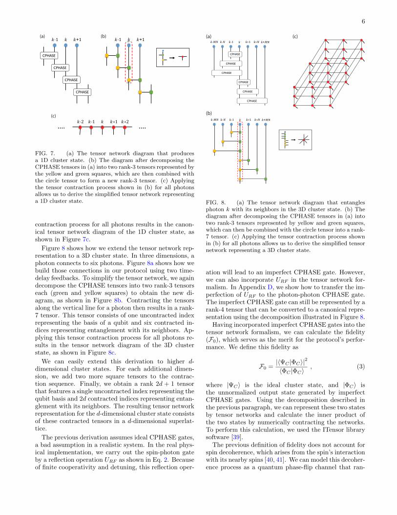
Figure 7 illustrates the tensor network representationfor a 1D cluster state, which we consider first before ex-tending to higher dimensions. In 1D cluster states, pho-ton k is connected to two photons, k− 1 and k+ 1. Fig-ure 7a shows the tensor network diagram where the pho-tons’ states and the two-qubit gates each have a tensorrepresentation. The blue circles are rank-1 tensors rep-resenting initially unentangled photons in state |+〉. Theboxes labeled CPHASE are rank-4 tensors representingCPHASE gates. The lines emerging from the blue circlesand boxes represent the indices of the tensors. Each rect-angle box has four lines, two pointing upward and twodownward. The upward lines represent the two inputqubits, and the downward lines represent the two out-put qubits. The lines connecting the circles and boxesrepresent the application of CPHASE gates between twophotons. The uncontracted downward lines represent thequbits for photons of the generated cluster state.
In canonical tensor network state representations suchas MPS and PEPS, each tensor represents one qubit,which may have multiple contracted indices but only oneuncontracted index. However, the diagram in Figure 7afeatures more tensors than qubits in the system, whichneeds to be simplified. We first decompose the CPHASEtensor into two rank-3 tensors using singular value de-composition (see Appendix C). Figure 7b shows the di-agram after the decomposition. The yellow and greensquares represent the two tensors decomposed from theCPHASE tensors, consisting of two vertical lines and onehorizontal line. Unlike the CPHASE tensors, the yellowand green tensors operate on one photon. We can thencontract tensors for a photon along its vertical line (seethe dashed box in Figure 7b), which allows us to obtain anew rank-3 tensor (see the solid box in Figure 7b). Thisrank-3 tensor has one uncontracted index representingthe qubit basis and two contracted indices representingentanglement with its neighbors. Applying this tensor
6
! !!"!"" !!#!"#
!!"!!!"!!"!!!"
!"#$%&
!"#$%&
!"#$%&
!"#$%&
(a) (b)
(c)
FIG. 7. (a) The tensor network diagram that producesa 1D cluster state. (b) The diagram after decomposing theCPHASE tensors in (a) into two rank-3 tensors represented bythe yellow and green squares, which are then combined withthe circle tensor to form a new rank-3 tensor. (c) Applyingthe tensor contraction process shown in (b) for all photonsallows us to derive the simplified tensor network representinga 1D cluster state.
contraction process for all photons results in the canon-ical tensor network diagram of the 1D cluster state, asshown in Figure 7c.
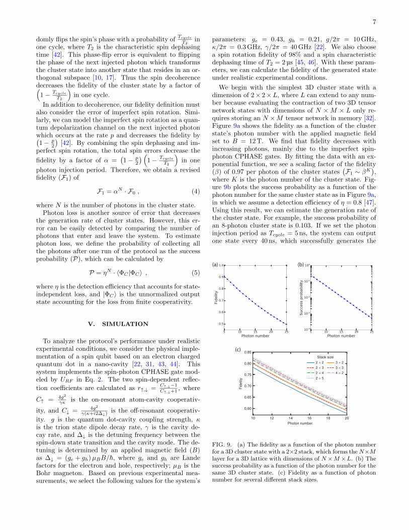
Figure 8 shows how we extend the tensor network rep-resentation to a 3D cluster state. In three dimensions, aphoton connects to six photons. Figure 8a shows how webuild those connections in our protocol using two time-delay feedbacks. To simplify the tensor network, we againdecompose the CPHASE tensors into two rank-3 tensorseach (green and yellow squares) to obtain the new di-agram, as shown in Figure 8b. Contracting the tensorsalong the vertical line for a photon then results in a rank-7 tensor. This tensor consists of one uncontracted indexrepresenting the basis of a qubit and six contracted in-dices representing entanglement with its neighbors. Ap-plying this tensor contraction process for all photons re-sults in the tensor network diagram of the 3D clusterstate, as shown in Figure 8c.
We can easily extend this derivation to higher d-dimensional cluster states. For each additional dimen-sion, we add two more square tensors to the contrac-tion sequence. Finally, we obtain a rank 2d + 1 tensorthat features a single uncontracted index representing thequbit basis and 2d contracted indices representing entan-glement with its neighbors. The resulting tensor networkrepresentation for the d-dimensional cluster state consistsof these contracted tensors in a d-dimensional superlat-tice.
The previous derivation assumes ideal CPHASE gates,a bad assumption in a realistic system. In the real phys-ical implementation, we carry out the spin-photon gateby a reflection operation URF as shown in Eq. 2. Becauseof finite cooperativity and detuning, this reflection oper-
!!"#!!"# ! !"$!!$ !"#!!#
!!"#!!"# ! !"$!!$ !"#
!"#$%&
!"#$%&
!!#
!"#$%&
!"#$%&
!"#$%&
!"#$%&
(a)
(b)
(c)
FIG. 8. (a) The tensor network diagram that entanglesphoton k with its neighbors in the 3D cluster state. (b) Thediagram after decomposing the CPHASE tensors in (a) intotwo rank-3 tensors represented by yellow and green squares,which can then be combined with the circle tensor into a rank-7 tensor. (c) Applying the tensor contraction process shownin (b) for all photons allows us to derive the simplified tensornetwork representing a 3D cluster state.
ation will lead to an imperfect CPHASE gate. However,we can also incorporate URF in the tensor network for-malism. In Appendix D, we show how to transfer the im-perfection of URF to the photon-photon CPHASE gate.The imperfect CPHASE gate can still be represented by arank-4 tensor that can be converted to a canonical repre-sentation using the decomposition illustrated in Figure 8.
Having incorporated imperfect CPHASE gates into thetensor network formalism, we can calculate the fidelity(F0), which serves as the merit for the protocol’s perfor-mance. We define this fidelity as
F0 =|〈ΨC |ΦC〉|2
〈ΦC |ΦC〉, (3)
where |ΨC〉 is the ideal cluster state, and |ΦC〉 isthe unnormalized output state generated by imperfectCPHASE gates. Using the decomposition described inthe previous paragraph, we can represent these two statesby tensor networks and calculate the inner product ofthe two states by numerically contracting the networks.To perform this calculation, we used the ITensor librarysoftware [39].
The previous definition of fidelity does not account forspin decoherence, which arises from the spin’s interactionwith its nearby spins [40, 41]. We can model this decoher-ence process as a quantum phase-flip channel that ran-
7
domly flips the spin’s phase with a probability ofTcycle
T2in
one cycle, where T2 is the characteristic spin dephasingtime [42]. This phase-flip error is equivalent to flippingthe phase of the next injected photon which transformsthe cluster state into another state that resides in an or-thogonal subspace [10, 17]. Thus the spin decoherencedecreases the fidelity of the cluster state by a factor of(
1− Tcycle
T2
)in one cycle.
In addition to decoherence, our fidelity definition mustalso consider the error of imperfect spin rotation. Simi-larly, we can model the imperfect spin rotation as a quan-tum depolarization channel on the next injected photonwhich occurs at the rate p and decreases the fidelity by(1− p
2
)[42]. By combining the spin dephasing and im-
perfect spin rotation, the total spin errors decrease the
fidelity by a factor of α =(1− p
2
) (1− Tcycle
T2
)in one
photon injection period. Therefore, we obtain a revisedfidelity (F1) of
F1 = αN · F0 , (4)
where N is the number of photons in the cluster state.Photon loss is another source of error that decreases
the generation rate of cluster states. However, this er-ror can be easily detected by comparing the number ofphotons that enter and leave the system. To estimatephoton loss, we define the probability of collecting allthe photons after one run of the protocol as the successprobability (P), which can be calculated by
P = ηN · 〈ΦC |ΦC〉 , (5)
where η is the detection efficiency that accounts for state-independent loss, and |ΦC〉 is the unnormalized outputstate accounting for the loss from finite cooperativity.
V. SIMULATION
To analyze the protocol’s performance under realisticexperimental conditions, we consider the physical imple-mentation of a spin qubit based on an electron chargedquantum dot in a nano-cavity [22, 31, 43, 44]. Thissystem implements the spin-photon CPHASE gate mod-eled by URF in Eq. 2. The two spin-dependent reflec-
tion coefficients are calculated as r↑,↓ =C↑,↓−1C↑,↓+1 , where
C↑ = 4g2
γκ is the on-resonant atom-cavity cooperativ-
ity, and C↓ = 4g2
γ(κ+i2∆↓)is the off-resonant cooperativ-
ity. g is the quantum dot-cavity coupling strength, κis the trion state dipole decay rate, γ is the cavity de-cay rate, and ∆↓ is the detuning frequency between thespin-down state transition and the cavity mode. The de-tuning is determined by an applied magnetic field (B)as ∆↓ = (ge + gh)µBB/~, where ge and gh are Landefactors for the electron and hole, respectively; µB is theBohr magneton. Based on previous experimental mea-surements, we select the following values for the system’s
parameters: ge = 0.43, gh = 0.21, g/2π = 10 GHz,κ/2π = 0.3 GHz, γ/2π = 40 GHz [22]. We also choosea spin rotation fidelity of 98% and a spin characteristicdephasing time of T2 = 2 µs [45, 46]. With these param-eters, we can calculate the fidelity of the generated stateunder realistic experimental conditions.
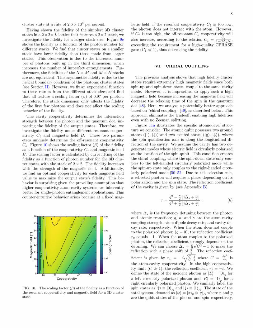
We begin with the simplest 3D cluster state with adimension of 2× 2×L, where L can extend to any num-ber because evaluating the contraction of two 3D tensornetwork states with dimensions of N ×M × L only re-quires storing an N ×M tensor network in memory [32].Figure 9a shows the fidelity as a function of the clusterstate’s photon number with the applied magnetic fieldset to B = 12 T. We find that fidelity decreases withincreasing photons, mainly due to the imperfect spin-photon CPHASE gates. By fitting the data with an ex-ponential function, we see a scaling factor of the fidelity(β) of 0.97 per photon of the cluster states
(F1 ∼ βK
),
where K is the photon number of the cluster state. Fig-ure 9b plots the success probability as a function of thephoton number for the same cluster state as in Figure 9a,in which we assume a detection efficiency of η = 0.8 [47].Using this result, we can estimate the generation rate ofthe cluster state. For example, the success probability ofan 8-photon cluster state is 0.103. If we set the photoninjection period as Tcycle = 5 ns, the system can outputone state every 40 ns, which successfully generates the
10 12 14 16 18 20Photon number
0.60
0.65
0.70
0.75
0.80
0.85
Fide
lity
Stack size2×22×32×42×5
3×23×34×2
(a) (b)
(c)
FIG. 9. (a) The fidelity as a function of the photon numberfor a 3D cluster state with a 2×2 stack, which forms theN×Mlayer for a 3D lattice with dimensions of N ×M ×L. (b) Thesuccess probability as a function of the photon number for thesame 3D cluster state. (c) Fidelity as a function of photonnumber for several different stack sizes.
8
cluster state at a rate of 2.6× 10⁶ per second.
Having shown the fidelity of the simplest 3D clusterstates in a 2×2×L lattice that features a 2×2 stack, weinvestigate the fidelity for a larger stack size. Figure 9cshows the fidelity as a function of the photon number fordifferent stacks. We find that cluster states on a smallerstack have lower fidelity than those made from largerstacks. This observation is due to the increased num-ber of photons built up in the third dimension, whichincreases the number of imperfect entanglements. Fur-thermore, the fidelities of the N ×M and M ×N stacksare not equivalent. This asymmetric fidelity is due to thehelical boundary condition of the photonic cluster states(see Section II). However, we fit an exponential functionto these results from the different stack sizes and findthat all feature a scaling factor (β) of 0.97 per photon.Therefore, the stack dimension only affects the fidelityof the first few photons and does not affect the scalingbehavior of the fidelity.
The cavity cooperativity determines the interactionstrength between the photon and the quantum dot, im-pacting the fidelity of the output states. Therefore, weinvestigate the fidelity under different resonant cooper-ativity C↑ and magnetic field B. These two param-eters uniquely determine the off-resonant cooperativityC↓. Figure 10 shows the scaling factor (β) of the fidelityas a function of the cooperativity C↑ and magnetic fieldB. The scaling factor is calculated by curve fitting of thefidelity as a function of photon number for the 3D clus-ter states with the stack of 2 × 2. The fidelity increaseswith the strength of the magnetic field. Additionally,we find an optimal cooperativity for each magnetic fieldvalue to maximize the output state’s fidelity. This be-havior is surprising given the prevailing assumption thathigher cooperativity atom-cavity systems are inherentlybetter for single-photon entanglement applications. Thiscounter-intuitive behavior arises because at a fixed mag-
10 20 30 40 50Cooperativity
8
9
10
11
12
13
14
15
16
Mag
netic
fiel
d (T
)
0.95
0.95 0.96
0.96
0.97
0.97
0.975
0.98
0.90
0.92
0.94
0.96
0.98
Scal
ing
fact
or
FIG. 10. The scaling factor (β) of the fidelity as a function ofthe resonant cooperativity and magnetic field for a 3D clusterstate.
netic field, if the resonant cooperativity C↑ is too low,the photon does not interact with the atom. However,if C↑ is too high, the off-resonant C↓ cooperativity will
also increase, according to the relation C↓ =C↑
1+i2∆z/κ,
exceeding the requirement for a high-quality CPHASEgate (C↓ � 1), thus decreasing the fidelity.
VI. CHIRAL COUPLING
The previous analysis shows that high fidelity clusterstates require extremely high magnetic fields since bothspin-up and spin-down states couple to the same cavitymode. However, it is impractical to apply such a highmagnetic field because increasing the magnetic field willdecrease the relaxing time of the spin in the quantumdot [48]. Here, we analyze a potentially better approachbased on “chiral coupling” [49], as described below. Thisapproach eliminates the tradeoff, enabling high fidelitieseven with no Zeeman splitting.
Figure 11a illustrates the specific atomic-level struc-ture we consider. The atomic qubit possesses two groundstates (|↑〉 , |↓〉) and two excited states (|⇑〉 , |⇓〉), wherethe spin quantization axis is along the longitudinal di-rection of the cavity. We assume the cavity has two de-generate modes whose electric field is circularly polarizedat the location of the spin-qubit. This condition createsthe chiral coupling, where the spin-down state only cou-ples to the left-handed circularly polarized mode whilethe spin-up state only couples to the right-handed circu-larly polarized mode [50–52]. Due to this selection rule,a reflected photon will acquire a phase depending on itspolarization and the spin state. The reflection coefficientof the cavity is given by (see Appendix B)
r =g2 − γ
2
[i∆s + κ
2
]g2 + γ
2
[i∆s + κ
2
] , (6)
where ∆s is the frequency detuning between the photonand atomic transition; g, κ, and γ are the atom-cavitycoupling strength, atom dipole decay rate, and cavity de-cay rate, respectively. When the atom does not coupleto the polarized photon (g = 0), the reflection coefficientr0 equals −1. When the atom couples to the polarizedphoton, the reflection coefficient strongly depends on thedetuning. We can choose ∆s = κ
2
√C2 − 1 to make the
reflection with a phase shift of π2 . The reflection coef-
ficient is given by r1 = −i√
C−1C+1 where C = 4g2
γκ is
the atom-cavity cooperativity. In the high cooperativ-ity limit (C � 1), the reflection coefficient r1 = −i. Wedefine the state of the incident photon as |L〉 = |0〉p for
a left circularly polarized photon and |R〉 = |1〉p for aright circularly polarized photon. We similarly label thespin states as |↑〉 ≡ |0〉A and |↓〉 ≡ |1〉A. The state of thetotal system, denoted as |ψ〉 = |x〉p⊗|y〉A where x and yare the qubit states of the photon and spin respectively,

9
!"#
!
"
$"#
#
$
(a)
(b) (c)
FIG. 11. (a) The level structures of a cavity-coupled atomicqubit in chiral coupling. LCP/RCP means left/right-handedcircularly polarized light. (b) Contour plots showing the scal-ing factor (β) of the fidelity as a function of the cooperativityand spin error. (c) The fidelity as a function of the photonnumber in cluster states with cooperativity C = 100, spinrotation error p = 0.001, and dephasing time T2 = 5 µs.
transforms according to the following operator
UCR =
r1 0 0 00 −1 0 00 0 −1 00 0 0 r1
. (7)
This transformation is not a CPHASE gate but can eas-ily be transformed into one by applying phase shiftsto the spin and photon given by the phase operator(
1 00 i
)⊗(
1 00 i
). This CPHASE gate does not require
large Zeeman splitting between the two optical transi-tions. It only requires high cooperativity to achieve highfidelity.
We now analyze the fidelity of cluster states generatedusing chiral coupling. Figure 11b plots the scaling factor(β) of the fidelity for a 3D cluster state as a function of
the cooperativity C and spin error 1−(1− p
2
) (1− τ
T2
),
which accounts for both imperfect spin rotation and de-phasing as defined previously. The fidelity increases withthe cooperativity until an upbound determined by thespin error. This is because the CPHASE gate is nearlyperfect when the cooperativity is large, and the spin er-ror will be the only factor affecting the fidelity of clusterstates. We can achieve a scaling factor of the fidelityof about 0.999 with a spin error rate of 0.001, which isabove the threshold (an error rate of 0.75%) of fault-tolerant cluster state quantum computation [2]. Thesespin error rates are achievable in both atomic [53–55] andsolid-state qubits [56], but combining these error rates
with high cooperativities remains a significant challenge.Figure 11c plots the fidelity as a function of the num-ber of photons in the cluster state with cooperativityC = 100, spin rotation error p = 0.001, and dephasingtime T2 = 5 µs. By fitting the data with an exponen-tial function, we see a fidelity decay factor of 0.998 perphoton of the cluster states
(F1 ∼ 0.998K
).
VII. CONCLUSION AND OUTLOOK
We have proposed and analyzed a protocol that canefficiently generate multi-dimensional photonic clusterstates using an atom-cavity system and a small numberof time-delay feedback. The protocol is deterministic un-der ideal conditions and therefore could achieve scalablephotonic cluster states. Our results highlight the impor-tance of chiral coupling to achieve high fidelity withoutthe need for extremely large Zeeman splitting that re-quires impractical magnetic fields. A note added that arecent paper by Kianna et al. [57] also proposed a pro-tocol to generate three-dimensional cluster states usingconstant ancilla and delay lines. They gave a good anal-ysis of the propagation of Pauli errors in the generatedstates. In comparison, our work demonstrates a physicalimplementation using an atom-cavity system. We alsoprovide a formalism to bridge and analyze the experimen-tal imperfections and the logical errors of the generatedstates.
The decomposing and contracting method of derivingtensor network states, as shown in Figures 7 and 8, isalso valuable for broader scenarios of generating multi-qubit states. For example, this method provides a di-agrammatic derivation of matrix product states (MPS)sequentially generated by a single-photon source in a cav-ity [35, 36]. One can also include errors by replacing theunitary operators with Kraus operators [58, 59]. Fur-thermore, our derivation has a particular advantage insimulating projected entangled pair states (PEPS) gen-erated using delay lines. In those systems, some qubitscan interact multiple times, which implements the logicallong-range interactions, such that a tensor network rep-resentation of the state is hard to calculate. However, ourmethod can solve it by decomposing the two-qubit oper-ators into two “entangled” local operator tensors. Thetensor network state is calculated by contracting the op-erator tensors of one site. A potential application of themethod is the simulation of high-dimensional Boson sam-pling [38, 60].
For future studies, we expect to apply the time-delayfeedback method to generate other types of tensor net-work states such as the Toric Code [61]. Ultimately, ourprotocol provides a versatile way to engineer complex en-tanglement that could enable a variety of applications inmeasurement-based quantum computation, quantum er-ror correction, and quantum communication.

10
ACKNOWLEDGMENTS
The authors would like to acknowledge support fromthe Air Force Office of Scientific Research (Grant No.FA9550-16-1-0323, FA95501610421), the Physics Fron-tier Center at the Joint Quantum Institute, the Na-tional Science Foundation (Grant No. PHYS. 1915371,OMA1936314, ), and the Maryland-ARL Quantum Part-nership.
Appendix A: Derivation of the quantum circuit forgenerating cluster states
We first prove the quantum circuit in Figure 2b gener-ates the nearest neighbor entanglement between photonsin a linear chain (1D cluster state). We start with a rep-resentation of 1D cluster state with K + 1 qubits [3]
|Ψ1D〉 =
K∏k=1
Zk−1,k|+〉A⊗|+〉⊗K
, (A1)
where Zi,j is the CPHASE gate between qubit i and j;the 0th qubit represents the ancilla (A), and other num-bered qubits represent photons. We introduce a swapoperator Si,j which exchanges the states between qubit iand j. Thus, Eq. A1 can be rewritten as
|Ψ1D〉 =
K∏k=1
SA,kZA,k|+〉A⊗|+〉⊗K
. (A2)
The product is ordered from right to left, i.e.∏Ki=1 Ui =
UK · · ·U1. We can use the relation
SA,kZA,k|φ〉A ⊗ |+〉k = (HA ⊗Hk)ZA,k|φ〉A ⊗ |+〉k ,(A3)
where |φ〉A is an arbitrary state of the ancilla; HA andHk are Hadamard gates on the ancilla and the photon,respectively. This relation holds when the photon is instate |+〉, but the ancilla can be in an arbitrary state,either unentangled or entangled. Using the relation, wereformulate Eq. A2 as
|Ψ1D〉 =
K∏k=1
(HA ⊗Hk)ZA,k|+〉A⊗|+〉⊗K
, (A4)
which is implemented by the quantum circuit in Fig-ure 2b.
We now prove Figure 2d generates the non-nearestneighbor entanglement between photons k − N and k.Based on the one-dimensional cluster state, we can addone dimension by entangling photons k −N and k as
|Ψ2D〉 =
K∏k=N+1
Zk−N,k
K∏k=1
Zk−1,k|+〉A⊗|+〉⊗K
. (A5)
Because CPHASE gates Zi,j commute each other, we canreorder the operators in Eq. A5
|Ψ2D〉 =
K∏k=N+1
Zk−1,kZk−N,k
×N∏k=1
Zk−1,k|+〉A⊗|+〉⊗K
. (A6)
By introducing the swap operator Si,j as in the one-dimensional case, we can rewrite Eq. A6 as
|Ψ2D〉 =
K∏k=N+1
SA,kZA,kZA,k−N
×N∏k=1
SA,kZA,k|+〉A⊗|+〉⊗K
. (A7)
After using the relation of Eq. A3, we rewrite Eq. A7 as
|Ψ2D〉 =
K∏k=N+1
(HA ⊗Hk)ZA,kZA,k−N
×N∏k=1
(HA ⊗Hk)ZA,k|+〉A⊗|+〉⊗K
. (A8)
Therefore, we first generate a 1D cluster state. Basedon it, the quantum circuit in Figure 2d implements the
iterative steps of∏Kk=N+1 (HA ⊗Hk)ZA,kZA,k−N , which
entangles photon k with photons k − N and k − 1, togenerate the 2D cluster state.
Then we prove that Figure 3b generates the unit cell ofthe 3D cluster state. By implementing two non-nearestneighbor gates to the linear chain of photons, the 3Dcluster state can be generated by
|Ψ3D〉 =
K∏k=MN+1
Zk−MN,k
K∏k=N+1
Zk−N,k
×K∏k=1
Zk−1,k|+〉A⊗|+〉⊗K
. (A9)
Because Zi,j commute with each other, we can reorderthe operators in Eq. A9
|Ψ3D〉 =
K∏k=MN+1
Zk−1,kZk−N,kZk−MN,k
×MN∏
k=N+1
Zk−1,kZk−N,k
×N∏k=1
Zk−1,k|+〉A⊗|+〉⊗K
. (A10)
After introducing the swap operator Si,j between the

11
qubit i and j, we can rewrite Eq. A10 as
|Ψ3D〉 =
K∏k=MN+1
SA,kZA,kZA,k−NZA,k−MN
×MN∏
k=N+1
SA,kZA,kZA,k−N
×N∏k=1
SA,kZA,k|+〉A⊗|+〉⊗K
. (A11)
The operators in the second and third parentheses gener-ate the 2D cluster state with dimensions of M×N . Withthe relation of Eq. A3, we can rewrite the operators inthe first parenthesis as
|Ψ3D〉 =
K∏k=N+1
(HA ⊗Hk)ZA,kZA,k−NZA,k−MN
×|Ψ2DM×N〉 . (A12)
The quantum circuit in Figure 3b implements the iter-
ative steps of∏Kk=N+1 (HA ⊗Hk)ZA,kZA,k−NZA,k−MN
in Eq. A12, which generates the 3D cluster state basedon a 2D cluster state.
Appendix B: Derivation of the reflection coefficient
The Hamiltonian of the atom-cavity system in Figure 4is given by H = H0 + V , where
H0 = ~ωca†a+ ~ωsσ⇑⇑ + ~ (ωs − δ1)σ⇓⇓ + ~δ2σ↓↓
V = i~gV σ⇑↑a+ i~gV σ⇓↓a+ i~gCσ⇓↑a+i~σ⇑↓a+h.c. .
We assume the cavity only support the vertically polar-ized mode, so gC = 0 and gV = g. The atomic state spacecan be reduced into two uncoupled subspaces {|↑〉 , |⇑〉}and {|↓〉 , |⇓〉}. In either subspace, the Heisenberg equa-tions of motion for the cavity field operator a, the atomicoperator σ−, and the external field input-output relationare given by [29, 62]
dadt = −
[i (ωc − ω) + γ
2
]a− gσ− −
√γain
dσ−dt = −
[i (ωs − ω) + κ
2
]σ− − gσza
aout = ain +√γa
, (B1)
where ωc, ωs, and ω are the frequencies of cavity field,atomic transition, and probe beam (external field); g,κ, and γ are the atom-cavity coupling strength, atomdipole decay rate, and cavity decay rate, respectively. Weconsider the singly-photon process, and the system oper-ates in the linear weak excitation limit where σz = −1.We also assume that the photon is quasi-monochromatic,which results in a steady-state reflection coefficient of
r (ω) = 1−γ[i (ωs − ω) + κ
2
][i (ωs − ω) + κ
2
] [i (ωc − ω) + γ
2
]+ g2
.
(B2)
We assume the cavity mode is on-resonant with the fre-quency of the external field (ωc = ω) and define the de-tuning ∆ = ωs − ω, so the spin-dependent reflection co-efficient is given by
r↑,↓ =g2 − γ
2
[i∆↑,↓ + κ
2
]g2 + γ
2
[i∆↑,↓ + κ
2
] , (B3)
where ∆↑ = 0, and ∆↓ = δ1 + δ2 detunes by the Zeemansplitting.
For the system in Figure 11a, we assume the cavity hastwo degenerate modes whose electric field is circularly po-larized at the location of the spin-qubit. When the probephoton is in circular polarization, the total atomic statespace can be reduced into two uncoupled state subspaces{|↑〉 , |⇑〉} and {|↓〉 , |⇓〉}. The reflection coefficient of thecavity can be calculated by considering either of the sub-space. When the spin is in the subspace of {|↑〉 , |⇑〉}, theHamiltonian is given by H = H0 + V , where
H0= ~ωca†a+ ~ωsσ⇑⇑V = i~gσ⇑↑a− i~gσ↑⇑a† .
The operators’ equations of motion are the same asEq. B1, and we can get the reflection coefficient as
r =g2 − γ
2
[i∆s + κ
2
]g2 + γ
2
[i∆s + κ
2
] , (B4)
where ∆s is the frequency detuning between the photonand atomic transition; g, κ, and γ are the atom-cavitycoupling strength, atom dipole decay rate, and cavitydecay rate, respectively.
Appendix C: Tensor decomposition
In this appendix, we explain how to decompose theCPHASE gate. We first write the matrix element ofCPHASE gate between qubit i and j as
Zi,j = Zα,βα′,β′ |α′, β′〉〈α, β|i,j . (C1)
Then we can partially transpose the matrix as
Zi,j = Zβ′,β
α′,α |α′〉〈α|i ⊗ |β
′〉〈β|j . (C2)
Then we can do a Singular Value Decomposition on the
matrix Zβ′,β
α′,αon its row indices (α′α) and column indices
(β′β) as
Zβ′,β
α′,α =∑s
Usα′αΛsVsβ′β∗ , (C3)
where U and V are unitary, and Λ is positive. Then wecan take the square root of Λ and combine it into U andV as
Asα′α = Usα′α√
Λs , (C4)
Bsβ′β = V sβ′β∗√Λs , (C5)

12
we use Einstein’s notation to omit summation operators.So we can represent the CPHASE tensor Z by the mul-tiplication of two tensors A and B as
Zβ′,β
α′,α = Asα′αBsβ′β . (C6)
In Figure 7b, we draw tensor A as a yellow square andtensor B as a green square. The α, α′ and β, β′ are in-dices represent the basis of the qubit, and s are indexrepresenting the entanglement bond between qubits.
Appendix D: Derivation of the imperfectphoton-photon CPHASE gate
In this appendix, we show the imperfect reflection op-eration U in Eq. 2 will result in an effective imperfectphoton-photon CPHASE gate. The quantum circuit inFigure 3b entangles photon k with its neighbors in three-dimensional cluster states. We can represent the circuitin an operator form as
E = Hs ⊗HkZs,kZs,k−NZs,k−MN . (D1)
In the real physical implementation, we should replacethe ideal CPHASE gates Z by the reflection opera-
tor Us,k = (I + εRs,k)Zs,k, where εR = UZ − I and
ε ∼ O(∣∣∣1− C↑−1
C↑+1
∣∣∣+∣∣∣1 +
C↓−1C↓+1
∣∣∣) indicates the order of
errors. Thus, Eq. D1 transforms as
E1 = (Hs ⊗Hk) (I + εRs,k)Zs,kUs,k−NUs,k−MN . (D2)
By commuting Hs ⊗ Hk and I + εRs,k then using therelation of Eq. A3, we can simplify Eq. D2 as
E1 = Us,kUk,k−NUk,k−MNSs,k , (D3)
where Ss,k is the swap gate between the ancilla and pho-
ton k, and Us,k = [I + ε (Hs ⊗Hk)Rs,k (Hs ⊗Hk)]Zs,kis also an imperfect CPHASE gate with the error in O (ε).Finally, we achieve an effective operation for entanglingphoton k with its six neighbors as
E = Uk+MN,kUk+N,kUk+1,kUk,k−NUk,k−MNUk,k−1 ,(D4)
where U denotes the gate between nearest neighbors, Udenotes the gate between non-nearest neighbors.
[1] R. Raussendorf and H. J. Briegel, A one-way quantumcomputer, Physical Review Letters 86, 5188 (2001).
[2] R. Raussendorf, J. Harrington, and K. Goyal, Topologi-cal fault-tolerance in cluster state quantum computation,New Journal of Physics 9, 199 (2007).
[3] H. J. Briegel and R. Raussendorf, Persistent entangle-ment in arrays of interacting particles, Physical ReviewLetters 86, 910 (2001).
[4] S. Muralidharan and P. K. Panigrahi, Perfect telepor-tation, quantum-state sharing, and superdense codingthrough a genuinely entangled five-qubit state, PhysicalReview A - Atomic, Molecular, and Optical Physics 77,032321 (2008).
[5] Z. M. Liu and L. Zhou, Quantum Teleportation of aThree-qubit State using a Five-qubit Cluster State, Inter-national Journal of Theoretical Physics 53, 4079 (2014).
[6] D. Schlingemann and R. F. Werner, Quantum error-correcting codes associated with graphs, Physical ReviewA - Atomic, Molecular, and Optical Physics 65, 8 (2002).
[7] B. A. Bell, D. A. Herrera-Martı, M. S. Tame,D. Markham, W. J. Wadsworth, and J. G. Rarity, Exper-imental demonstration of a graph state quantum error-correction code, Nature Communications 5, 1 (2014).
[8] N. Friis, D. Orsucci, M. Skotiniotis, P. Sekatski, V. Dun-jko, H. J. Briegel, and W. Dur, Flexible resources forquantum metrology, New Journal of Physics 19, 063044(2017).
[9] N. Shettell and D. Markham, Graph States as a Resourcefor Quantum Metrology, Physical Review Letters 124,110502 (2020).
[10] R. Raussendorf, D. E. Browne, and H. J. Briegel,Measurement-based quantum computation on clusterstates, Physical Review A - Atomic, Molecular, and Op-tical Physics 68, 32 (2003).
[11] B. P. Lanyon, P. Jurcevic, M. Zwerger, C. Hempel,E. A. Martinez, W. Dur, H. J. Briegel, R. Blatt, andC. F. Roos, Measurement-based quantum computationwith trapped ions, Physical Review Letters 111, 210501(2013).
[12] H. Pichler, S. Choi, P. Zoller, and M. D. Lukin, Uni-versal photonic quantum computation via time-delayedfeedback, Proceedings of the National Academy of Sci-ences 114, 11362 (2017).
[13] I. Dhand, M. Engelkemeier, L. Sansoni, S. Barkhofen,C. Silberhorn, and M. B. Plenio, Proposal for QuantumSimulation via All-Optically-Generated Tensor NetworkStates, Physical Review Letters 120, 130501 (2018).
[14] M. Gimeno-Segovia, T. Rudolph, and S. E. Economou,Deterministic Generation of Large-Scale Entangled Pho-tonic Cluster State from Interacting Solid State Emit-ters, Physical Review Letters 123, 070501 (2019),arXiv:1801.02599.
[15] M. V. Larsen, X. Guo, C. R. Breum, J. S. Neergaard-Nielsen, and U. L. Andersen, Deterministic generation ofa two-dimensional cluster state, Science 366, 369 (2019).
[16] W. Asavanant, Y. Shiozawa, S. Yokoyama, B. Charoen-sombutamon, H. Emura, R. N. Alexander, S. Takeda,J. ichi Yoshikawa, N. C. Menicucci, H. Yonezawa, andA. Furusawa, Generation of time-domain-multiplexedtwo-dimensional cluster state, Science 366, 373 (2019).

13
[17] N. H. Lindner and T. Rudolph, Proposal for pulsed On-demand sources of photonic cluster state strings, PhysicalReview Letters 103, 113602 (2009).
[18] I. Schwartz, D. Cogan, E. R. Schmidgall, Y. Don,L. Gantz, O. Kenneth, N. H. Lindner, and D. Gershoni,Deterministic Generation of a Cluster State of EntangledPhotons, Science 354, 434 (2016).
[19] S. E. Economou, N. Lindner, and T. Rudolph, Opticallygenerated 2-dimensional photonic cluster state from cou-pled quantum dots, Physical Review Letters 105, 093601(2010).
[20] L. M. Duan and H. J. Kimble, Scalable photonic quantumcomputation through cavity-assisted interactions, Physi-cal Review Letters 92, 127902 (2004).
[21] H. Kim, R. Bose, T. C. Shen, G. S. Solomon, andE. Waks, A quantum logic gate between a solid-statequantum bit and a photon, Nature Photonics 7, 373(2013).
[22] S. Sun, H. Kim, G. S. Solomon, and E. Waks, A quan-tum phase switch between a single solid-state spin and aphoton, Nature Nanotechnology 11, 539 (2016).
[23] S. Sun, H. Kim, Z. Luo, G. S. Solomon, and E. Waks, Asingle-photon switch and transistor enabled by a solid-state quantum memory, Science 361, 57 (2018).
[24] Z. Luo, S. Sun, A. Karasahin, A. S. Bracker, S. G. Carter,M. K. Yakes, D. Gammon, and E. Waks, A Spin-PhotonInterface Using Charge-Tunable Quantum Dots StronglyCoupled to a Cavity, Nano Letters 19, 7072 (2019).
[25] A. Reiserer, N. Kalb, G. Rempe, and S. Ritter, A quan-tum gate between a flying optical photon and a singletrapped atom, Nature 508, 237 (2014).
[26] B. Hacker, S. Welte, G. Rempe, and S. Ritter, A pho-ton–photon quantum gate based on a single atom in anoptical resonator, Nature 536, 193 (2016).
[27] R. E. Evans, M. K. Bhaskar, D. D. Sukachev, C. T.Nguyen, A. Sipahigil, M. J. Burek, B. Machielse, G. H.Zhang, A. S. Zibrov, E. Bielejec, H. Park, M. Loncar,and M. D. Lukin, Photon-mediated interactions betweenquantum emitters in a diamond nanocavity, Science 362,662 (2018).
[28] D. Press, T. D. Ladd, B. Zhang, and Y. Yamamoto, Com-plete quantum control of a single quantum dot spin usingultrafast optical pulses, Nature 456, 218 (2008).
[29] D. F. Walls and G. J. Milburn, Quantum Optics(Springer Berlin Heidelberg, 2008) pp. 1–425.
[30] J. L. O’Brien, Optical Quantum Computing, Science318, 1567 (2008).
[31] S. G. Carter, T. M. Sweeney, M. Kim, C. S. Kim,D. Solenov, S. E. Economou, T. L. Reinecke, L. Yang,A. S. Bracker, and D. Gammon, Quantum control of aspin qubit coupled to a photonic crystal cavity, NaturePhotonics 7, 329 (2013).
[32] R. Orus, A practical introduction to tensor net-works: Matrix product states and projected entan-gled pair states, Annals of Physics 349, 117 (2014),arXiv:1306.2164.
[33] G. Vidal, Efficient simulation of one-dimensional quan-tum many-body systems, Physical Review Letters 93,040502 (2004).
[34] F. Verstraete and J. I. Cirac, Renormalization algorithmsfor Quantum-Many Body Systems in two and higher di-mensions (2004), arXiv:cond-mat/0407066 [cond-mat].
[35] C. Schon, E. Solano, F. Verstraete, J. I. Cirac, andM. M. Wolf, Sequential generation of entangled multi-
qubit states, Physical Review Letters 95, 110503 (2005),arXiv:0501096 [quant-ph].
[36] C. Schon, K. Hammerer, M. M. Wolf, J. I. Cirac, andE. Solano, Sequential generation of matrix-product statesin cavity QED, Physical Review A - Atomic, Molecular,and Optical Physics 75, 032311 (2007), arXiv:0612101[quant-ph].
[37] S. Xu and S. Fan, Generate tensor network state by se-quential single-photon scattering in waveguide QED sys-tems, APL Photonics 3, 116102 (2018).
[38] M. Lubasch, A. A. Valido, J. J. Renema, W. S.Kolthammer, D. Jaksch, M. S. Kim, I. Walmsley, andR. Garcıa-Patron, Tensor network states in time-binquantum optics, Physical Review A 97, 062304 (2018),arXiv:1712.09869.
[39] M. Fishman, S. R. White, and E. M. Stoudenmire, TheITensor Software Library for Tensor Network Calcula-tions (2020), arXiv:2007.14822.
[40] A. V. Khaetskii, D. Loss, and L. Glazman, Electron spindecoherence in quantum dots due to interaction with nu-clei, Physical Review Letters 88, 1868021 (2002).
[41] J. R. Maze, J. M. Taylor, and M. D. Lukin, Electronspin decoherence of single nitrogen-vacancy defects in di-amond, Physical Review B - Condensed Matter and Ma-terials Physics 78, 094303 (2008).
[42] A. N. Michael and L. C. Isaac, Quantum Computa-tion and Quantum Information 10th Anniversary Edition(2010).
[43] K. Hennessy, A. Badolato, M. Winger, D. Gerace,M. Atature, S. Gulde, S. Falt, E. L. Hu, andA. Imamoglu, Quantum nature of a strongly coupled sin-gle quantum dot-cavity system, Nature 445, 896 (2007).
[44] J. R. Schaibley, A. P. Burgers, G. A. McCracken, L. M.Duan, P. R. Berman, D. G. Steel, A. S. Bracker, D. Gam-mon, and L. J. Sham, Demonstration of quantum entan-glement between a single electron spin confined to anInAs quantum dot and a photon, Physical Review Let-ters 110, 167401 (2013).
[45] D. Press, K. De Greve, P. L. McMahon, T. D. Ladd,B. Friess, C. Schneider, M. Kamp, S. Hofling, A. Forchel,and Y. Yamamoto, Ultrafast optical spin echo in a singlequantum dot, Nature Photonics 4, 367 (2010).
[46] F. H. L. Koppens, K. C. Nowack, and L. M. K. Vander-sypen, Spin Echo of a Single Electron Spin in a QuantumDot, Physical Review Letters 100, 236802 (2008).
[47] M. K. Bhaskar, R. Riedinger, B. Machielse, D. S. Lev-onian, C. T. Nguyen, E. N. Knall, H. Park, D. En-glund, M. Loncar, D. D. Sukachev, and M. D. Lukin,Experimental demonstration of memory-enhanced quan-tum communication, Nature 580, 60 (2020).
[48] C.-Y. Lu, Y. Zhao, A. N. Vamivakas, C. Matthiesen,S. Falt, A. Badolato, and M. Atature, Direct measure-ment of spin dynamics in InAs/GaAs quantum dots usingtime-resolved resonance fluorescence, PHYSICAL RE-VIEW B 81, 10.1103/PhysRevB.81.035332 (2010).
[49] P. Lodahl, S. Mahmoodian, S. Stobbe, A. Rauschenbeu-tel, P. Schneeweiss, J. Volz, H. Pichler, and P. Zoller,Chiral quantum optics, Nature 541, 473 (2017).
[50] C. Junge, D. O’Shea, J. Volz, and A. Rauschenbeutel,Strong coupling between single atoms and nontransversalphotons, Physical Review Letters 110, 213604 (2013).
[51] I. Shomroni, S. Rosenblum, Y. Lovsky, O. Bechler,G. Guendelman, and B. Dayan, All-optical routing of sin-gle photons by a one-atom switch controlled by a single

14
photon, Science 345, 903 (2014).[52] S. Barik, A. Karasahin, S. Mittal, E. Waks, and
M. Hafezi, Chiral quantum optics using a topological res-onator, Physical Review B 101, 205303 (2020).
[53] W. C. Campbell, J. Mizrahi, Q. Quraishi, C. Senko,D. Hayes, D. Hucul, D. N. Matsukevich, P. Maunz, andC. Monroe, Ultrafast gates for single atomic qubits, Phys-ical Review Letters 105, 090502 (2010).
[54] T. P. Harty, D. T. C. Allcock, C. J. Ballance, L. Guidoni,H. A. Janacek, N. M. Linke, D. N. Stacey, and D. M. Lu-cas, High-fidelity preparation, gates, memory, and read-out of a trapped-ion quantum bit, Physical Review Let-ters 113, 220501 (2014).
[55] J. P. Gaebler, T. R. Tan, Y. Lin, Y. Wan, R. Bowler,A. C. Keith, S. Glancy, K. Coakley, E. Knill, D. Leibfried,and D. J. Wineland, High-Fidelity Universal Gate Set forBe 9 + Ion Qubits, Physical Review Letters 117, 060505(2016), arXiv:1604.00032.
[56] J. Yoneda, K. Takeda, T. Otsuka, T. Nakajima, M. R.Delbecq, G. Allison, T. Honda, T. Kodera, S. Oda,Y. Hoshi, N. Usami, K. M. Itoh, and S. Tarucha, Aquantum-dot spin qubit with coherence limited by chargenoise and fidelity higher than 99.9%, Nature Nanotech-nology 13, 102 (2018).
[57] K. Wan, S. Choi, I. H. Kim, N. Shutty, and P. Hayden,Fault-tolerant qubit from a constant number of compo-nents (2020), arXiv:2011.08213.
[58] F. Verstraete, J. J. Garcıa-Ripoll, and J. I. Cirac, Ma-trix product density operators: Simulation of finite-temperature and dissipative systems, Physical ReviewLetters 93, 207204 (2004).
[59] M. Zwolak and G. Vidal, Mixed-state dynamics in one-dimensional quantum lattice systems: A time-dependentsuperoperator renormalization algorithm, Physical Re-view Letters 93, 207205 (2004), arXiv:0406440 [cond-mat].
[60] A. Deshpande, A. Mehta, T. Vincent, N. Quesada,M. Hinsche, M. Ioannou, L. Madsen, J. Lavoie,H. Qi, J. Eisert, D. Hangleiter, B. Fefferman, andI. Dhand, Quantum Computational Supremacy viaHigh-Dimensional Gaussian Boson Sampling (2021),arXiv:2102.12474.
[61] A. Y. Kitaev, Fault-tolerant quantum computation byanyons, Annals of Physics 303, 2 (2003).
[62] C. Y. Hu, A. Young, J. L. O’Brien, W. J. Munro, andJ. G. Rarity, Giant optical Faraday rotation induced bya single-electron spin in a quantum dot: Applicationsto entangling remote spins via a single photon, PhysicalReview B - Condensed Matter and Materials Physics 78,085307 (2008).