detection and remediation of soil and aquifer systems contaminated with petroleum products: an...
TRANSCRIPT

Ž .Journal of Petroleum Science and Engineering 26 2000 169–178www.elsevier.nlrlocaterjpetscieng
Detection and remediation of soil and aquifer systemscontaminated with petroleum products: an overview
Farhad Nadim a,), George E. Hoag a, Shili Liu a, Robert J. Carley a, Peter Zack b
a EnÕironmental Research Institute, UniÕersity of Connecticut, Longley Building 146, Box U-210, Route 44, Storrs, CT 06269, USAb Department of EnÕironmental Protection, CT, USA
Received 12 December 1998; accepted 15 December 1999
Abstract
Fate of organic chemicals in the subsurface strata is not very well understood. It has only been a decade or two thatenvironmental scientists are focusing their attentions on remediating sites that are contaminated with organic chemicals.Different routes of soil and groundwater contamination by petroleum hydrocarbon compounds and their partitioning intogaseous, aqueous and pure phases in the subsurface strata are discussed. A summary of the techniques used for treatinghydrocarbon-contaminated soil and groundwater and their application limitations are presented. United States Environmental
Ž .Protection Agency’s US-EPA methods 8260, 8270 and 418.1 for detection and quantitation of petroleum rangehydrocarbon in soil and aqueous samples and some recently developed mathematical models used to predict the fate andtransport of petroleum range compounds in aquifer systems are briefly discussed. Results of some toxicological studies onlight and heavy petroleum hydrocarbon are presented. It is concluded that reaching an environment free of hydrocarboncontamination needs broad public understanding of the risks associated with these compounds. Proper management andcareful handling of petroleum products reduces the possibility of spills. Replacing old and leaking underground storage tankswith new double wall tanks equipped with leak detectors and cathodic protection could significantly improve the quality ofour precious and fragile groundwater resources. q 2000 Elsevier Science B.V. All rights reserved.
Keywords: groundwater; hydrocarbon; soil analysis; volatile compounds
1. Introduction
Petroleum hydrocarbon originates from liquid fos-sil fuels called oil or more properly petroleum.Petroleum is a naturally occurring liquid with widely
) Corresponding author. Tel.: q1-860-486-4015; fax: q1-860-486-5488.
E-mail addresses: [email protected],Ž [email protected] F. Nadim .
different composition and complexity. Except for afew surface seepages, the vast portion of petroleumis located well below the surface of the earth and itis extracted only by drilling. Crude oil is a complexmixture of hydrocarbons. Its elemental compositionis carbon–hydrogen, with variable quantities of oxy-gen and sulfur, and trace amounts of nitrogen, metalsand other elements. Modern refineries use a proce-dure called AcrackingB to fractionate unused cuts. Inthis process, the material is heated to temperaturesabove 2308C at different pressures with or without acatalyst. Cracking converts heavy and complex hy-
0920-4105r00r$ - see front matter q 2000 Elsevier Science B.V. All rights reserved.Ž .PII: S0920-4105 00 00031-0

( )F. Nadim et al.rJournal of Petroleum Science and Engineering 26 2000 169–178170
drocarbons to more simple molecules with lowerboiling points with the loss of hydrogen. Variousfractions of petroleum products ranging from methaneto asphalthene are produced during this process.
At every point in the oil production, distribution,and consumption process, oil is invariably stored instorage tanks. The potential for an oil spill is signifi-cant, and the effects of spilled oil many times poseserious threats to the environment. Leaking under-ground and aboveground storage tanks, improperdisposal of petroleum wastes, and accidental spillsare major routes of soil and groundwater contamina-tion with petroleum products. The most commonroute of soil and groundwater contamination is leak-ing underground storage tanks that are used by gasstations, commercial, industrial, and residential com-pounds. Underground storage tanks that are not pro-tected against corrosion with cathodic protection andare not designed in double wall with reinforcedfiberglass to withstand ground subsidence are verylikely to fail and cause massive leaks in the groundŽ .U.S. EPA, 1998 . The subsurface medium must beprotected against any kind of hazardous contamina-tion because soil acts as a permanent residence forpollutants and the dynamic movements of hydrologi-cal cycle transports them to groundwater aquifersŽ .Huling and Weaver, 1996 . Once a liquid petroleumproduct is released into the ground it partitions intothree separate phases: dissolved, liquid and gas. Asmall fraction of the petroleum hydrocarbon dis-solves in the soil moisture or groundwater, a portionof the product remains in soil pore space in its pureliquid form as residual saturation and some of itevaporates into the air of soil pores. Pure phaseliquids that do not readily dissolve in water are
Ž .called non-aqueous phase liquids NAPL . In generalNAPLs are subdivided into two classes: those that
Ž .are lighter than water LNAPLs and those with aŽ .density greater than water DNAPLs . Hydrocarbon
fuels such as gasoline, heating fuel, kerosene, jet fueland aviation fuel are LNAPLs. Benzene, toluene,
Ž .ethylbenzene, and xylene BTEX are light aromatichydrocarbons that have relative high water solubili-
Ž . Ž .ties 150–1800 mgrl Howard et al., 1991 . Labora-tory studies have revealed BTEX to be acutely toxicfor laboratory animals. Long-term gastrointestinaland respiratory exposures of mouse and rats to BTEX
Žhave produced liver cancer and leukemia Budavari
.et al., 1989 . The volume fraction of BTEX ingasoline can be as high as 20%. BTEX may also bepresent in other petroleum products in lower fractionŽ .American Petroleum Institute, 1985 . Methyl-tert-
Ž .butyl ether MTBE , an octane enhancer is an oxy-genate and a substitute for lead in gasoline. Due tothe presence of an oxygen atom in its structure,MTBE has a relatively high water solubility and itsvolume fraction in gasoline may range from 0% to
Ž .15% Howard et al., 1997 .
2. Aqueous solubility of petroleum products
Petroleum compounds are sparingly soluble inaqueous systems. Their solubilities decrease with
Ž .increasing molecular size Peters and Luthy, 1993 .Solubility of petroleum compounds is also a functionof their mole fraction. For petroleum molecules thatare liquid at ambient temperatures, solubility in wa-ter can be estimated with the following equationŽ .Schwartzenbach et al., 1993 .
X sg X gy1 1Ž .w org . mix org . mix w
X is the mole fraction solubility of petroleumw
hydrocarbon constituents, X is the mole frac-org. mixŽtion of hydrocarbon constituent in mixture for ex-
. y1ample mole fraction of toluene in gasoline , and gw
is the ability of organic molecule to dissolve in wateror the pure phase aqueous solubility of hydrocarbonconstituents. In most petroleum products such asgasoline, diesel fuel and fuel oil, the mixture maybeconsidered as an ideal solution and the activity coef-
Ž .ficient of each compound g maybe consid-org. mix
ered being equal to one. For heavy petroleum com-pounds such as naphthalene, and isoparaffins that aresolid at ambient temperatures in their pure phase,
Ž .Peters and Luthy 1993 used the following equationto estimate the aqueous solubilities of heavypetroleum molecules:
C sX S f rf . 2Ž . Ž .Ž .pure ii i i L S
Where the term on the right shows the ratio of thepure component fugacities in the subcooled liquidand the solid phases. C is the aqueous solubility ofi
Ž .compound i in mixture, X is the mole fraction, Si i
is the pure phase aqueous solubility, f and f areL S

( )F. Nadim et al.rJournal of Petroleum Science and Engineering 26 2000 169–178 171
Table 1Solubilities of BTEX in a mixture of fresh gasoline and deionized water at 258C
Petroleum Benzene Toluene Ethylbenzene o-Xylene m-Xylene p-XyleneŽ . Ž . Ž . Ž . Ž . Ž .compound mgrl mgrl mgrl mgrl mgrl mgrl
Solubility in mixture 51.4 29.2 3.8 6.2 9.2 3.4Solubility in pure phase 1791 534.8 140 175 146 156
the fugacities of the pure compound in the subcooledliquid and solid phases, respectively.
In 1985, the American Petroleum Institute con-ducted a study on solubilities of petroleum hydrocar-bons in groundwater. In a simple laboratory experi-ment, one part gasoline with 10 parts water wasplaced in a sealed vessel and the mixture was rotatedfor 96 h. Concentrations of BTEX in the mixturewere determined with aliquots taken from the aque-ous phase and subsequent measurements with aGCrMSD. The reported solubilities of some gaso-line components as the average of five experimentsand their pure phase solubilities are given in Table 1Ž .American Petroleum Institute, 1985 .
3. Distribution of petroleum contaminants in thesubsurface zone
Petroleum hydrocarbon molecules are usuallylighter than water and shortly after a spill they forma pool of NAPL over the surface of water table.Portion of the NAPL phase that is in contact with thegroundwater slowly dissolves in groundwater andforms a plume of hydrocarbon in the flowing
Fig. 1. A typical leaking underground tank with contaminantplume.
groundwater. The plume’s front mostly contains thelighter and more soluble hydrocarbon compounds.Fig. 1 shows a typical leaking underground storagetank with air sparging and vapor extraction systemsfor clean-up.
In the unsaturated zone, portion of petroleumŽ .products remains as residual pure product NAPL .
Residual NAPL is held in soil pores either by capil-lary forces or as small pools of liquids over clay andsilt lenses. If not removed, residual petroleum hydro-carbon acts as a permanent source of contamination
Ž .in the ground. Soil vapor extraction SVE and airsparging have the capability of removing NAPL ifthe flow of air is not restricted by chanelling orexistence of natural barriers.
If the density of the contaminant plume is signifi-cantly higher from the native groundwater, the con-taminant plume moves deep into the aquifer and maynot be detected with shallow monitoring systems.
4. Current clean-up techniques
4.1. In situ soil Õapor extraction
Volatile and some semi-volatile organic com-Ž .pounds VOCs and Semi-VOCs can be removed
from unsaturated soils by a process known as SVE.Chemicals that have boiling points lower than 2208Cin an environment with one atmospheric pressure can
Ž . Žbe considered as volatile compounds Fig. 1 U.S..EPA, 1996 . SVE brings fresh atmospheric air into
contact with the contaminated subsurface by an in-duced vacuum. The continuous flow of air throughthe porous soil removes the NAPL, as well as thedissolved and the sorbed phases. SVE is an in situclean-up process meaning that soils can be remedi-ated without disturbance or excavation. SVE brings

( )F. Nadim et al.rJournal of Petroleum Science and Engineering 26 2000 169–178172
fresh atmospheric air into contact with the contami-nated subsurface by an induced vacuum. The contin-uous flow of air through the porous soil removes theNAPL, as well as the dissolved and the sorbedphases into the moving air. When applied in thefield, best results can be obtained if the subsoilstratum is uniform with high porosity and low mois-ture content and air streams follow a horizontal path.High concentrations of organic matter in soil canadsorb VOCs and may retard their volatilizationprocess. Experimental results have shown that theNAPL phase is extracted from the contaminated soilin the early stages of vapor extraction Removal ofthe remaining portion of the compounds requiresvolatilization from the dissolved aqueous phase to-gether with desorption from the solid surfaces into
Ž .the dissolved aqueous phase Nadim et al., 1997 .
4.2. In situ steam injection Õapor extraction
If the temperature of VOC and semi-VOCs in-creases, they can be stripped from soil at a muchfaster pace with vapor extraction wells. In situ steamextraction is a new technology and has had limiteduse in the United States. Steam extraction can beused in two different systems; mobile and stationary.The mobile system has a unit that volatilizes contam-inants in small areas in a sequential manner byinjecting steam and hot air through rotating cutterblades that pass through the contaminated medium.The stationary system uses steam injection as ameans to volatilize and displace contaminants fromthe undisturbed subsurface soil. In both systems,
Ž . Ž .steam at 2008C and compressed air at 1358C isforced through the soil medium and the mixture ofair, vapor and chemicals are collected by extractionwells. In one pilot study, steam extraction alone wasable to remove 90% of soil contamination
4.3. Air sparging
Air sparging is a method of site remediation thatŽ .introduces air or other gases into the saturated zone
contaminated with VOCs. In addition to volatiliza-tion of VOCs, air sparging promotes the growth ofaerobic bacteria in saturated zones and may oxidizereduced chemical species. SVE wells are placed insites where air sparging is applied and they extract
the volatilized contaminants that are transported toŽthe unsaturated zone by air sparging Hoag et al.,
.1996 .Ž .Hinchee 1994 categorizes air sparging as two
distinct technologies, in-well aeration and the injec-tion of air into the saturated zone. In-well aeration isthe injection of air below the water table in a well,producing a physical change in the ground watersystem known as the Aairlift pump effectB. As airbubbles move upward in the well and reach thewater surface, they create a relative vacuum behindin their flow paths. This pressure difference causesthe ground water to move into the well from thebottom screens and return to the aquifer from theshallower portion of the screens. This movement ofground water into the bottom of the well results inVOCs entering the well as they are stripped fromsolution with the sparging gas. A major draw back inthis system is the gradual build up of bacteria andinorganic precipitation in the vicinity of the wellscreens that can significantly reduce the circulationof water and the sparging efficiency. The objectiveof the second air sparging technique is to injectpressurized air into the aquifer material through thewell screens or diffusers. It has been reported thatthe injected air into the aquifer migrates in stablechannels and only the contaminated soil within thesechannels are exposed to the injected air. If stable airchannels form in the aquifer by air injection, the onlyremoval process of the contaminants not in directcontact with the airflow paths would be liquid phase
Ž .diffusion Hoag et al., 1996 .Equilibrium partitioning of the contaminants at
the gasrwater interface can be written as: C sg
C H, where C is the gaseous concentration inaq g
terms of milligram per liter, C is the aqueousaq
concentration in milligram per liter, and H is thedimensionless Henry’s law constant. This relationcan be used to describe the partitioning of gas andwater in the sparging system. The efficiency withwhich air sparging transfers oxygen to water is mea-sured by determining the rate at which the dissolvedoxygen concentration of ground water increases. In-crease in oxygen concentration depends on the par-tial pressure of oxygen in the sparging gas, which inpart depends on the gauge pressure of the air pump.In a study conducted by Hoag, 1996, a gauge pres-sure of 0.96 atm was required to induce air sparging,

( )F. Nadim et al.rJournal of Petroleum Science and Engineering 26 2000 169–178 173
8 m below the water table in an aquifer formation ofsilt and sand.
4.4. Pump and treat
Pump and treat is a technique that extracts con-taminated groundwater from the subsurface with theuse of extraction wells. Contaminated groundwater istreated by air stripping, passage through activatedcarbon or bioremediation. This treatment techniqueis usually accompanied with in situ vapor extractionto enhance the removal of residual volatile hydrocar-bon from the zone of fluctuating groundwater. Thistechnique is not effective for low permeable aquifers,may require long-term pumping and treating and
Ž .may require discharge permits U.S. EPA, 1993 .
4.5. Vacuum-enhanced pump and treat
A surface-mounted vacuum pump that removessoil hydrocarbon vapors and contaminated ground-water simultaneously can increase the pumping re-covery rate 3 to 10 times, reducing the remediationcost and time. This remediation method is effectivefor aquifers with low permeability. Limitations asso-ciated with this technique are; requirement of avapor treatment system, production of large quanti-ties of water in a short period of time and quick dropin water table that may lead to smearing of contami-
Ž .nants U.S. EPA, 1993 .
4.6. In situ bioremediation
Naturally occurring soil microbes may be able tobiodegrade hydrocarbons and other organic com-pounds in unsaturated soil and aquifers if the level ofcontamination is low and does not produce toxicityfor the active bacteria. However, in many cases, it ispossible to enhance the ability of naturally occurringbacteria to degrade organic contaminants by the ad-dition of nutrients, oxygen and water. Jamison, Ray-mond, and Hudson carried out one of the early worksof enhanced bioremediation in the United States in1975 to remediate a groundwater aquifer that wascontaminated with high-octane gasoline. Inorganicnitrogen and phosphorus were added through injec-tion wells and air was supplied by sparging wells.The bacteria population increased by a factor of
1000 shortly after the addition of nutrients and 10months after the beginning of the project no trace of
Žgasoline was detected in groundwater Huling and.Weaver, 1996 .
In situ bioremediation would produce optimumresults if the NAPL source were removed from thecontaminated soil. The in situ biodegradation projectcan not be successful if nutrients and oxygen do notreach the contaminated zone. The soil stratum shouldhave sufficient permeability to allow movement ofoxygen and nutrients. Extreme pH ranges in soil canreduce microbial diversity and activity. SVE and airsparging enhance bioactivity in soil due to continu-ous supply of oxygen to the contaminated zone.
4.7. Fate and transport of petroleum hydrocarbon insoil: mathematical approach
Most geological formations are heterogeneous.Uniform and homogeneous formations are very rare.Advection–diffusion models that consider theaquifers to be heterogeneous and incorporate molec-ular diffusion into low permeability layers depict abetter picture of solute movement in the ground.Aquifer heterogeneity is not the only factor con-tributing to the spread of contaminants. Divergingand converging flow lines can spread contaminants
Žover a larger cross-section of the aquifer Fetter,.1993 . Seasonal variations in the water table can
change the direction of groundwater flow and con-tribute to the lateral spread of contaminants. Varia-tions in the contaminant concentrations at the sourcecan lead to apparent dispersion in the longitudinaldirection.
5. Description of mathematical models
5.1. Disperse
Disperse is an advection–dispersion model thatcalculates the size and direction of a MTBE and
Ž .tert-butyl alcohol TBA plumes. Paul Bauer of theNew Jersey Department of Environmental Protection
Ž .developed this model Bauer, 1998 . The model isconservative and assumes no adsorption and nodegradation. Therefore, the actual size of the plumesimulates worst case scenarios. The model predicts

( )F. Nadim et al.rJournal of Petroleum Science and Engineering 26 2000 169–178174
Fig. 2. Location of contaminant source and the calibration well.
the maximum distance downgradient from the sourceat which the action level is exceeded.
The following conditions must be satisfied for thismodel:
1. All sources are identified and removed.2. No further action in remediating soil or ground-
water will be taken.3. Aquifer is homogeneous.4. Average groundwater velocity is constant in time.5. The dispersion coefficient is constant and propor-
tional to the velocity.
The peak concentration and the distance betweenthe source area and the calibration wells control the
Ž .calculated length of the plume Fig. 2 .
5.2. HyperÕentilate
Hyperventilate is a software guidance system forŽ .vapor extraction soil venting applications. Hyper-
ventilate was developed by Paul Johnson of Shell OilŽ .Co. U.S. EPA, 1992; Johnson et al., 1990 . Hyper-
ventilate will:
Ž .a Identify and characterize required site-specificdata.Ž .b Decide if soil venting is appropriate for acertain site.Ž .c Evaluate air permeability test results.Ž .d Calculate the minimum number of vapor ex-traction wells.Ž .e Quantify how results for a certain site mightdiffer from the ideal case.
The software performs all necessary calculationsand contains Ahelp cardsB that define the equationsused, perform unit conversions, and provide supple-mentary information on related topics.
5.3. Air3D
Air3D adapts the groundwater flow simulatorŽMODFLOW a modular three-dimensional finite-dif-
.ference groundwater flow model to simulate airflowŽ .in the unsaturated zone Joss and Baher, 1995 .
Ž .A pre-processor PREAIR uses pneumatic andgeologic information to create data files in a formatconsistent with MODFLOW input requirements.MODFLOW can be used to numerically solve thepartial-differential equation governing airflow be-cause the airflow equation has been cast in a formatconsistent with the groundwater flow equation. A
Ž .post-processor POSTAIR then transforms outputfrom MODFLOW into dimensionally consistent air-flow output, pressure, mass flow rates, and volumet-ric flow rates.
AIR3D takes advantage of the facility and thecomputational power of MODFLOW by transform-ing the airflow equation into a form equivalent to thegroundwater flow equation solved by MODFLOW.Transformation and data input for the simulation isaccomplished with the preprocessor Fortran programcalled PREAIR.
5.4. Diffusion–desorption model
The diffusion–desorption model is a microscalemathematical model that was developed by Nadim et
Ž .al. 1997 , to analyze the desorption rate limitedextraction of volatile organic compounds in soilcolumns. By solving the diffusion equation in theliquid layer around the soil particles and incorporat-ing the effects of slow desorption from the soilsurfaces, it is found that the concentration of organ-
Fig. 3. A schematic drawing of the mass transport region. Theorganic molecules are initially dissolved in the liquid layer oradsorbed on the soil surface at xs0. As the venting gas comesinto contact with the liquid, the organic molecules are extractedfrom the moist soil.
( )F. Nadim et al.rJournal of Petroleum Science and Engineering 26 2000 169–178 175
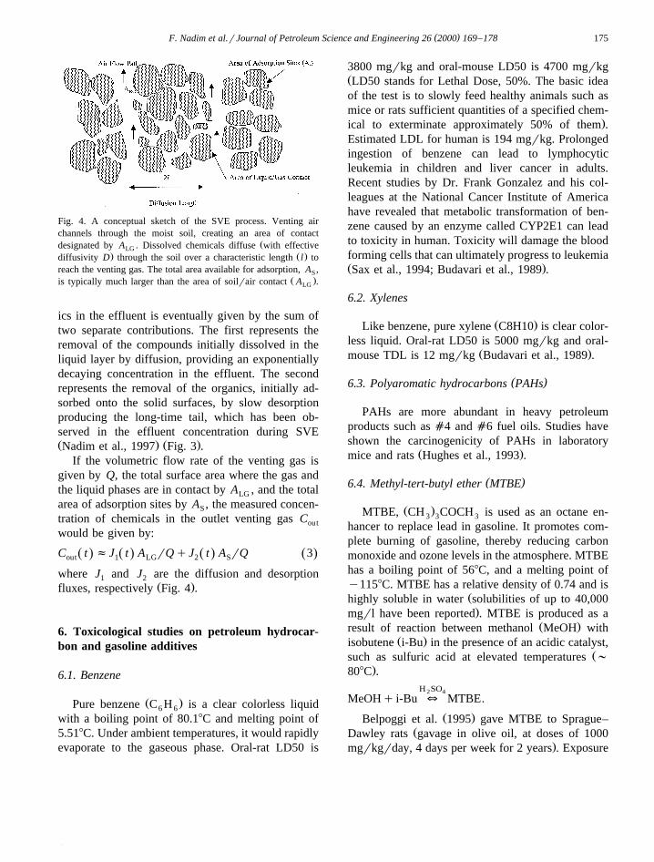
Fig. 4. A conceptual sketch of the SVE process. Venting airchannels through the moist soil, creating an area of contact
Ždesignated by A . Dissolved chemicals diffuse with effectiveLG. Ž .diffusivity D through the soil over a characteristic length l to
reach the venting gas. The total area available for adsorption, A ,SŽ .is typically much larger than the area of soilrair contact A .LG
ics in the effluent is eventually given by the sum oftwo separate contributions. The first represents theremoval of the compounds initially dissolved in theliquid layer by diffusion, providing an exponentiallydecaying concentration in the effluent. The secondrepresents the removal of the organics, initially ad-sorbed onto the solid surfaces, by slow desorptionproducing the long-time tail, which has been ob-served in the effluent concentration during SVEŽ . Ž .Nadim et al., 1997 Fig. 3 .
If the volumetric flow rate of the venting gas isgiven by Q, the total surface area where the gas andthe liquid phases are in contact by A , and the totalLG
area of adsorption sites by A , the measured concen-S
tration of chemicals in the outlet venting gas Cout
would be given by:
C t fJ t A rQqJ t A rQ 3Ž . Ž . Ž . Ž .out 1 LG 2 S
where J and J are the diffusion and desorption1 2Ž .fluxes, respectively Fig. 4 .
6. Toxicological studies on petroleum hydrocar-bon and gasoline additives
6.1. Benzene
Ž .Pure benzene C H is a clear colorless liquid6 6
with a boiling point of 80.18C and melting point of5.518C. Under ambient temperatures, it would rapidlyevaporate to the gaseous phase. Oral-rat LD50 is
3800 mgrkg and oral-mouse LD50 is 4700 mgrkgŽLD50 stands for Lethal Dose, 50%. The basic ideaof the test is to slowly feed healthy animals such asmice or rats sufficient quantities of a specified chem-
.ical to exterminate approximately 50% of them .Estimated LDL for human is 194 mgrkg. Prolongedingestion of benzene can lead to lymphocyticleukemia in children and liver cancer in adults.Recent studies by Dr. Frank Gonzalez and his col-leagues at the National Cancer Institute of Americahave revealed that metabolic transformation of ben-zene caused by an enzyme called CYP2E1 can leadto toxicity in human. Toxicity will damage the bloodforming cells that can ultimately progress to leukemiaŽ .Sax et al., 1994; Budavari et al., 1989 .
6.2. Xylenes
Ž .Like benzene, pure xylene C8H10 is clear color-less liquid. Oral-rat LD50 is 5000 mgrkg and oral-
Ž .mouse TDL is 12 mgrkg Budavari et al., 1989 .
( )6.3. Polyaromatic hydrocarbons PAHs
PAHs are more abundant in heavy petroleumproducts such as a4 and a6 fuel oils. Studies haveshown the carcinogenicity of PAHs in laboratory
Ž .mice and rats Hughes et al., 1993 .
( )6.4. Methyl-tert-butyl ether MTBE
Ž .MTBE, CH COCH is used as an octane en-3 3 3
hancer to replace lead in gasoline. It promotes com-plete burning of gasoline, thereby reducing carbonmonoxide and ozone levels in the atmosphere. MTBEhas a boiling point of 568C, and a melting point ofy1158C. MTBE has a relative density of 0.74 and is
Žhighly soluble in water solubilities of up to 40,000.mgrl have been reported . MTBE is produced as a
Ž .result of reaction between methanol MeOH withŽ .isobutene i-Bu in the presence of an acidic catalyst,
Žsuch as sulfuric acid at elevated temperatures ;.808C .
H SO2 4
MeOHq i-Bu m MTBE.
Ž .Belpoggi et al. 1995 gave MTBE to Sprague–ŽDawley rats gavage in olive oil, at doses of 1000
.mgrkgrday, 4 days per week for 2 years . Exposure

( )F. Nadim et al.rJournal of Petroleum Science and Engineering 26 2000 169–178176
caused a dose-related increase in the incidence ofcombined leukemia and lymphomas in the female
Žrats and an increase in Leydig cell adenomas benign.testicular tumors in the high-dose male rats. The
National Research Council Panel of America hasrecommended not using these tumor data in riskestimation until after a complete peer review of the
Ž .study. Concentrations of as low as 20 mgrl ofMTBE can cause unpleasant taste and odor in drink-
Ž .ing water Howard et al., 1997 .
7. U.S. EPA analytical methods for soil and wateranalysis
7.1. Method 8260
Method 8260 is used for analysis of volatileorganic compounds by gas chromatography and massspectrometry. This method can be used to detect andmeasure the concentration of VOCs in soil, air andaqueous systems. Due to recent advances in softwareengineering and instrumentation and the introductionof fast computers in the field of analytical chemistry,nearly all VOCs and some Semi-VOCs can be mea-sured with this method. In general, VOCs that haveboiling points less than 2008C can be quantified withthis method. Volatile, water-soluble compounds canbe included in this technique by the azeotropic distil-lation or closed-system vacuum distillation. Suchcompounds include low molecular weight halo-genated hydrocarbons, aromatics, ketones, nitriles,
Žacetates, acrylates, ethers, and sulfides U.S. EPA,.1996 .
Samples are introduced into the gas chromato-graph by the purge and trap methods or by directinjection. The analytes are introduced directly to awide-bore capillary column or cryo-focused on acapillary pre-column before being flash evaporatedto a narrow-bore capillary column for analysis. Thecolumn is temperature programmed to separate theanalytes, which are then detected with a mass spec-
Ž .trometer MS interfaced to the gas chromatograph.Method detection limits can be as low as 0.1 ppbŽ .mgrl for aqueous and mgrkg for solid matricesŽ .U.S. EPA, 1996 . Water samples are taken in glassVOC vials with Teflonw liner caps and no headspacein the vial to prevent the loss of volatile compounds.
One or two drops of 2 N HCl are added to thesample to prevent bacterial growth. Water samplescan be kept for a period of 2 weeks in refrigerator at48C. Soil samples are kept in the glass vials as watersamples and it is better to preserve the soil samplesin methanol prior to laboratory analysis.
7.2. Method 8270
Method 8270 is used to determine the concentra-tion of Semi-VOCs in extracts prepared from manytypes of solid waste matrices, soils, air samplingmedia and water samples.
Method 8270 can be used to quantify most neu-tral, acidic, and basic organic compounds that aresoluble in methylene chloride and capable of beingeluted as sharp peaks from a gas chromatographicfused-silica capillary column coated with a slightlypolar silicone. These compounds include polynuclear
Ž .aromatic hydrocarbons PAHs , chlorinated hydro-carbons and pesticides, phthalate esters, organophos-phate esters, nitrosamines, haloethers, aldehydes,ethers, ketones, anilines, pyridines, quinolines, aro-matic nitro compounds, and phenols.
The Semi-VOCs are introduced into the GCrMSby injecting the sample extract into a gas chromato-graph with a narrow-bore fused-silica capillary col-umn. Similar to method 8260, the GC-column istemperature programmed to separate the analytes,which are then detected with a mass spectrometerŽ .MS connected to the gas chromatograph. Analyteseluting from the capillary column are introduced intothe mass spectrometer via a jet separator or a directconnection. Identification of target compounds inboth methods 8260 and 8270 is accomplished bycomparing their mass spectra with the electron im-
Ž .pact or electron impact-like spectra of authenticstandards. Quantification is accomplished by com-paring the response of a major ion relative to aninternal standard using a five-point calibration curveŽ .U.S. EPA, 1996 .
( )7.3. Method 418.1 TPH-IR
Method 418.1 is used for the detection of totalŽ .petroleum hydrocarbon TPH in water samples. By
substituting a Soxhlet extraction procedure for theseparatory funnel procedure, this method may be

( )F. Nadim et al.rJournal of Petroleum Science and Engineering 26 2000 169–178 177
modified and used for the analysis of total petroleumhydrocarbon in solid matrices. Soxhlet extractionprocedure is a procedure for extracting non-VOCsand Semi-VOCs from solids, soils, sludges andwastes. The solid sample is mixed with anhydroussodium sulfate, placed in an extraction thimble orplugs of glass wool, and extracted using an appropri-
Ž .ate solvent in a Soxhlet extractor U.S. EPA, 1995 .Method 418.1 defines Aoil and greaseB as any
compound that can be extracted from a sample byFreon-113. Petroleum hydrocarbon, fatty matter andoil from animal and vegetable sources, waxes, or-ganic dyes, sulfur compounds, chlorophyll and othercompounds are included as extractable materialswithin this method.
After the extraction of oil and grease from asample, the ATotal Petroleum HydrocarbonsB arederived by adding silica gel to the Aoil and greaseBextracted from a sample. The role of silica gel is toadsorb the polar material such as vegetable oils andanimal fats. The method considers all Aoil andgreaseB materials that are not eliminated by silica gel
Žadsorption as Apetroleum hydrocarbonsB U.S. EPA,. Ž .1978 . An Infrared Spectrophotometer IR quanti-
fies the extracted petroleum hydrocarbon. The ab-sorbance of the extracted sample is measured at 2930cmy1, and compared to the absorbance of a knownstandard. There are several limitations associatedwith method TPH-IR that can be outlined in thethree following categories. First, compounds withhigh degree of volatility may be lost during analysis.Second, the method solvent is not strong at extract-
Žing heavy hydrocarbon molecules such as hydrocar-.bon molecules found in a4 and a6 fuel oils . And
third, the method does not have an analytical specifi-cation.
8. Conclusion
The major routes of aquifer contamination withpetroleum products are leaking underground storagetanks that are used by gas stations and industriesthroughout the world. For example in the state ofConnecticut with a population of less than 3 million,there are more than 4000 identified sites with leakingunderground storage tanks.
Due to the fast pace of progress in industrialfields, transportation and telecommunication, it seems
that our world today has become a small place tolive. Resources on our planet are limited and everysmall portion of water, soil and air must be pre-served. It has been estimated that 80% of world’spopulation depends on groundwater for survivalŽ .Moore, 1989 . When groundwater aquifers are con-taminated with organic chemicals such as gasolinecomponents, it may take years of efforts to remediatethem.
Leaks from underground tanks are not visible andunless the tremendous risks of groundwater contami-nation are well understood, local and governmentauthorities throughout the world will not initiatecorrective actions. Based on U.S. EPA clean-up stan-dards, 1 l of gasoline has the potential of contaminat-ing 2 million m3 of groundwater.
Petroleum products are mostly lighter than waterand when they reach aquifers a pool of floatingNAPL forms over the water table. The major prob-lem associated with subsurface petroleum contamina-tion is the dissolution of highly toxic light aromatichydrocarbons in ground water. The other problemthat has focused the attention of many water authori-ties in the industrial nations is the introduction ofoxygenated additives such as MTBE and TBA, sub-stituting lead in gasoline in the past decade. MTBEis highly soluble in aqueous systems. The environ-mental impacts of MTBE are not very well under-stood yet but from the public point of view traceconcentrations of this chemical in drinking waterŽ .10–20 mgrl can change the odor and taste ofwater to an undrinkable state and bringing up thedemand for extra and costly treatment.
Even at very low concentrations in water, organiccompounds can be very toxic because they are mostly
Ž .hydrophobic insoluble in water and in long-termexposures tend to bioaccumulate in human tissuesŽ .liver and kidneys .
Current site remediation techniques have manylimitations associated with them. Therefore, prevent-ing the spill of chemicals into the ecosystem is theultimate most important factor in preserving thegroundwater resources. By and large, a site contami-nated with organic pollutants may never be restoredto its conditions prior to anthropogenic pollution.
Environmental science has had significant im-provements in the past decade. There is hope thatsomeday our mother earth will free herself from

( )F. Nadim et al.rJournal of Petroleum Science and Engineering 26 2000 169–178178
anthropogenic pollution. However, a clean environ-ment may only be achieved if all people around theglobe place the idea of having a pollution-free planeton top of their agenda.
References
Ž .American Petroleum Institute API , 1985. Laboratory Study onSolubilities of Petroleum Hydrocarbons in Groundwater, TRCEnvironmental Consultants, 800 Connecticut Blvd., East Hart-ford, CT, USA.
Bauer, P., 1998. Disperse; AdvectionrDispersion Model forMTBE and TBA, Program Documentation. Department ofEnvironmental Protection, New Jersey.
Belpoggi, F., Soffritti, M., Maltoni, C., 1995. Methyl-tertiary-butylŽ .ether MTBE -a gasoline additive-causes testicular and
haematopoietic cancers in rats. Toxicol. Ind. Health 11, 119–149.
Ž .Budavari, S., O’Neil, M.J., Smith, A., Heckelman, P.E. Eds. ,The Merc Index: An Encyclopedia of Chemicals, Drugs, andBiologicals. Merck, Rahway, NJ.
Fetter, C.W., 1993. Contaminant Hydrogeology. Macmillan, NewYork.
Hinchee, R.E., 1994. Air sparging for site remediation. In:Ž .Hinchee, R.E. Ed. , Air Sparging State of the Art. Lewis
Publishers, Chelsea, MI, pp. 1–14.Hoag, G.E., Nadim, F., Liu, S., Dahmani, M.A., 1996. The
development of a rapid laboratory screening procedure for soilair-sparging with an automated purge and trap system. Pro-ceedings of the 51st Industrial Waste Conference at PurdueUniversity West Lafayette, USA. Ann Arbor Sci. Publ., AnnArbor, MI, pp. 115–122.
Howard, C.J., Russell, A., Atkinson, R., Calvert, J., 1997. Intera-gency Assessment of Oxygenated Fuels, National Science andTechnology Council, Committee on Environmental and Natu-ral Resources, Washington, DC.
Howard, P.H., Sage, G.W., Jarvis, W.F., Gray, D.A., 1991.Handbook of Environmental Fate and Exposure Data forOrganic Chemicals 2 Lewis Publishers, Chelsea, MI.
Hughes, N.C., Pfau, W., Hewer, A., Jacob, J., Grimmer, G.,Phillips, D.H., 1993. Covalent binding of polycyclic aromatichydrocarbon components of coal tar to dna in mouse skin.Carcinogenesis 14, 135–144.
Huling, S.G., Weaver, J.W., 1996. Dense nonaqueous phase liq-Ž .uids. In: Boulding, J.R. Ed. , EPA Environmental Engineer-
ing Sourcebook. Ann Arbor Sci. Publ., Chelsea, MI, pp.73–103.
Johnson, P.C., Kemblowski, M.W., Colthart, J.D., 1990. A practi-cal approach to the design, operation, and monitoring of in situsoil-venting systems. Ground Water Monitoring Review, 159–178, Spring.
Joss, C.J., Baher, A., 1995. Documentation of AIR3D, An Adapta-tion of the Ground-Water-Flow Code Modflow to SimulateThree-Dimensional Air Flow in the Unsaturated Zone, U.S.
Ž .Geological Survey Open-File Report 94-533 , U.S. Geologi-cal Survey, West Trenton, NJ.
Moore, W., 1989. Balancing the Needs of Water Use. Springer-Verlag, New York.
Nadim, F., Nadim, A., Hoag, G.E., Dahmani, M.A., 1997. Des-orption rate limitations in the extraction of organic moleculesfrom unsaturated soils during soil venting operations. Journalof Contaminant Hydrology 25, 21–37.
Peters, C.A., Luthy, R.G., 1993. Coal tar dissolution in water-mis-cible solvents: experimental evaluation. Environ. Sci. Technol.27, 2831–2843.
Sax, I.N., Feiner, B., Fitzgerald, J.J., Haley, T.J., Weisburger,E.K., 1994. Dangerous Properties of Industrial Materials. 6thedn. Van Nostrand-Reinhold, New York.
Schwartzenbach, R.P., Gschwend, P.M., Imboden, D.M., 1993.Environmental Organic Chemistry. Wiley, New York.
Ž .U.S. EPA, 1992. Solid Waste and Emergency Response OS-420WF, EPA 500-C-B-92-001, Hyperventilate Users Manual, ASoftware Guidance System Created for Vapor Extraction Ap-plications, U.S. Government Printing Office, Washington, DC.
U.S. EPA, 1978. Test Method for Evaluating Total RecoverableŽPetroleum Hydrocarbon, Method 418.1 Spectrophotometric,
.Infrared . U. S. Government Printing Office, Washington, DC.U.S. EPA, 1995., Method 3540, Soxhlet Extraction, SW-846, 3rd
Edition., Revision 2. U.S. Government Printing Office, Wash-ington, DC.
U.S. EPA, 1996., Test Methods for Evaluating Solid Waste,PhysicalrChemical Methods, Methods 8260-B for VolatileOrganic Compounds by Gas ChromatographyrMass Spec-
Ž .trometry GCrMS and 8270-C for Semi-volatile OrganicCompounds by Gas ChromatographyrMass SpectrometryŽ .GCrMS , SW-846, 3rd edn., U.S. Government Printing Of-fice, Washington, DC.
U.S. EPA, 1993., An Overview of Underground Storage TankRemediation Options, Solid Waste and Emergency Response,5403W, EPA 510-F-93-029. U.S. Government Printing Office,Washington, DC.
U.S. EPA, 1998. Code of Federal Regulations, CFR 40, Parts 281:Approval of the State Underground Storage Tank Programs,Office of the Federal Register National Archives and RecordsAdministration, U.S. Government Printing Office, Washing-ton, DC.