surfactant-enhanced aquifer remediation (sear ... · surfactant-enhanced aquifer remediation (sear)...
TRANSCRIPT
NAVAL FACILITIES ENGINEERING COMMAND Washington, DC 20374-5065
NFESC Technical Report
TR-2219-ENV
Surfactant-Enhanced Aquifer Remediation (SEAR) Implementation Manual
Prepared by:
Intera Inc. (formerly Duke Engineering & Services)
and
Naval Facilities Engineering Service Center
April 2003
Approved for public release; distribution is unlimited.

ACKNOWLEDGEMENTS
The initial version of this document was prepared by John Londergan at Intera, Inc. (formerly Duke Engineering & Services of Austin, TX). The final content editing and revision of this document has been performed by Laura Yeh of the Naval Facilities Engineering Service Center, who acknowledges her co-author, the influences of many peers and colleagues, including those in related fields, as well as feedback related to parallel documents and projects in progress, under the lead sponsorship of other organizations and agencies. The contributors to the first SEAR Design Manual are greatly thanked for their assistance.
i
CONTENTS
ACKNOWLEDGEMENTS...............................................................................................................i CONTENTS.......................................................................................................................................ii FIGURES...........................................................................................................................................iii TABLES.............................................................................................................................................iii ACRONYMS AND ABBREVIATIONS ..........................................................................................iv Section 1.0: INTRODUCTION ............................................................................................................1
1.1 Objective and Scope................................................................................................................ 1 1.2 Technology Review................................................................................................................. 1 1.3 Document Organization .......................................................................................................... 2
Section 2.0: FIELD PLANNING ACTIVITIES .....................................................................................4 2.1 Teaming................................................................................................................................... 4 2.2 Health & Safety....................................................................................................................... 4 2.3 Regulatory/Permitting Issues .................................................................................................. 4 2.4 Risk Management Issues ......................................................................................................... 6 2.5 Performance Assessment......................................................................................................... 7 2.6 Site Coordination Requirements ............................................................................................. 9
2.6.1 Water and Utilities ...................................................................................................... 9 2.6.2 Miscellaneous Logistics Issues................................................................................... 9
2.7 Pilot-Scale Investigations ........................................................................................................ 10 Section 3.0: SEAR SYSTEM COMPONENTS .....................................................................................12
3.1 Component Description........................................................................................................... 12 3.1.1 Chemicals Preparation .................................................................................................. 12
3.1.1.1 Batch Preparation Method............................................................................. 12 3.1.1.2 In-line Mixing Method .................................................................................. 14 3.1.1.3 Pre-mixing or Offsite Chemical Preparation ................................................. 14
3.1.2 Injection and Extraction Operations ............................................................................. 14 3.1.2.1 Injection and Extraction Wells ...................................................................... 14 3.1.2.2 Pumps and Plumbing ..................................................................................... 16
3.1.3 Monitoring System Parameters..................................................................................... 17 3.1.4 Process Control System ................................................................................................ 19 3.1.5 Wastewater Treatment .................................................................................................. 19
3.2 System Components Preparation............................................................................................. 21 Section 4.0: FIELD OPERATIONS ......................................................................................................22
4.1 System Initiation...................................................................................................................... 22 4.2 Flooding Operations................................................................................................................ 22
4.2.1 Injection Preparation and Quality ................................................................................. 23 4.2.1.2 Surfactant Injectate Preparation .................................................................... 23 4.2.1.3 Injectate Quality Control Measures.............................................................. 23
4.2.2 Monitoring Evaluation of Flooding Operations........................................................... 24 4.2.2.1 Flowrate, Water Level, and DNAPL Level Monitoring................................ 24 4.2.2.2 Effluent and Monitoring Sampling................................................................ 25 4.2.2.3 Wastewater Treatment Monitoring................................................................ 28
4.2.3 Sample Analysis............................................................................................................ 29 4.2.3.1. Surfactant Analysis ....................................................................................... 29 4.2.3.2 Analysis of Organics in the Presence of Surfactants..................................... 30 4.2.3.3 Other Sample Analysis .................................................................................. 30
4.2.4 Equipment Maintenance ............................................................................................... 30 4.3 System Shutdown .................................................................................................................... 31
ii

APPENDICES ...................................................................................................................................33
APPENDIX A. SURFACTANT FLOODING WELL CONSTRUCTION SPECIFICATIONS .......... A-1
APPENDIX B. MULTI-LEVEL SAMPLERS ...................................................................................... B-1
APPENDIX C. SURFACTANT TITRATION PROCEDURES FOR SODIUM DIHEXYLSULFOSUCCINATE..................................................................................C-1
APPENDIX D. COMPARISON OF FIELD DATA TO PREDICTED SEAR SIMULATION RESULTS.....................................................................................................................D-1
APPENDIX E. CONTRACTING GUIDANCE FOR REMEDIAL PROJECT MANAGERS ..............E-1
FIGURES
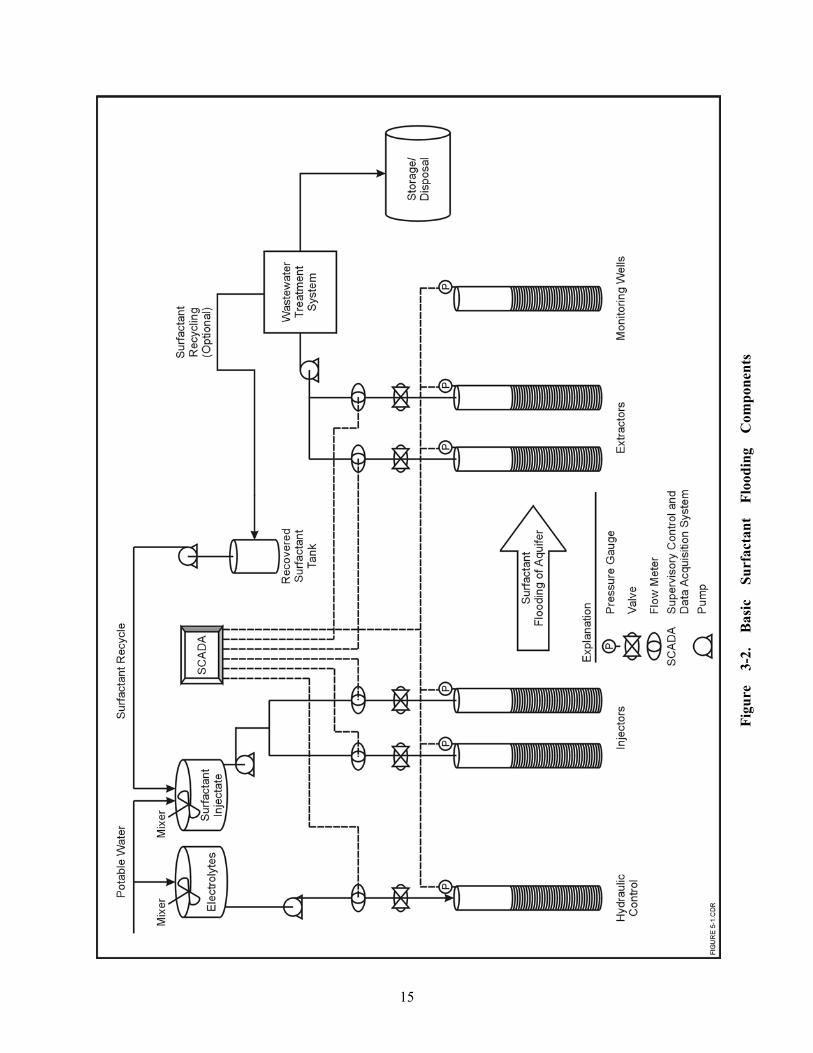
Figure 1-1. Flow Chart for Surfactant Flooding Implementation................................................................... 3 Figure 3-1. HDPE Storage Tanks Used for Blending Electrolyte Solutions .................................................. 13 Figure 3-2. Basic Surfactant Flooding Components Diagram........................................................................ 15 Figure 3-3. Temporary Tented Wastewater Treatment Facility ..................................................................... 20 Figure 4-1. Potentiometric Surface Map of Water Levels During Surfactant Flooding Operations.............. 26 Figure 4-2. Visual Monitoring Samples Collected from a SEAR Pilot Test.................................................. 27
TABLES
Table 3-1. SEAR System Monitoring Parameters .......................................................................................... 18
iii

ACRONYMS AND ABBREVIATIONS
CERCLA Comprehensive Environmental Response, Compensation and Liability Act cP centipoise DAS data acquisition system DNAPL dense nonaqueous phase liquid DQO data quality objective FID flame ionization detector GC gas chromatograph(y) GFI ground fault interruptors HDPE high density polyethylene HPLC high performance liquid chromatography ICP inductively coupled plasma IFT interfacial tension LNAPL light nonaqueous phase liquid MCL maximum contaminant levels mL milliliter MLS multi-level sampler NaCl sodium chloride NAPL nonaqueous phase liquid NPDES National Pollutant Discharge Elimination System PCE tetrachloroethylene or perchloroethylene PITT partitioning interwell tracer tests POTW public-owned treatment works PPE personal protective equipment RCRA Resource Conservation and Recovery Act RFP request for proposal SCADA Supervisory Control and Data Acquisition SDWA Safe Drinking Water Act SEAR Surfactant-enhanced aquifer remediation SOW Statement of Work TCD thermal conductivity detector TCE trichloroethylene UIC Underground Injection Control USDW underground sources of drinking water UTCHEM University of Texas Chemical Flooding Simulator VOC volatile organic compound wt% weight percent
iv

Section 1.0: INTRODUCTION
1.1 Objective and Scope The objective of this implementation manual is to familiarize remedial project managers and
engineers and scientists affiliated with environmental remediation projects on the major tasks and planning parameters involved with implementing an in-situ surfactant flood or surfactant-enhanced aquifer remediation (SEAR) project to remove dense non-aqueous phase liquids (DNAPLs). A companion technical manual has been produced on SEAR design focusing on removal of DNAPLs. It is hoped that in combination, the guiding principles presented in these two manuals will assist users in understanding basic design and implementation issues for attaining remedial objectives and in following risk management methodologies and approaches for avoiding misapplication of surfactant flooding for DNAPL removal. Cost-effective surfactant flooding performance demands recognition of the chemical flooding process, system specifications, and design and operational limitations, in order to secure the appropriate level of services and performance for the site.
This manual acknowledges that most key design parameters for surfactant flooding operations
have been determined with earlier process design (as covered in the SEAR Design Manual) and that technology implementation on a full-scale is intended, or that a requirement for a pilot-scale study exists to fully specify design parameters. Planning and field preparation aspects, general system component specifications, and performance-related issues will be detailed. As can be discerned from the design criteria introduced within the SEAR Design Manual, surfactant flooding mandates expertise in many diverse areas inclusive of DNAPL source zone characterization technologies, aquifer and aquitard testing methods, and the chemical and multi-phase fluid flow properties of pumped surfactant solutions. Field implementation will furthermore require skilled knowledge of field-scale chemical preparation methods and remediation engineering resources for controlled injection and extraction of chemical solutions throughout the contaminated aquifer zones, and decontamination of the remedial fluids.
1.2 Technology Review SEAR is a technology addressing the removal of immiscible-phase liquid contaminants, also
termed nonaqueous phase liquids (NAPLs), from the saturated zone. In recent years, it has been further developed to be applicable to the removal of dense NAPL contaminants or DNAPLs such as TCE and PCE, which are amongst the most recalcitrant groundwater contaminants to be addressed in source zones or contamination source areas. Often likened as a chemical enhancement to pump and treat operations, aggressive source reduction technologies such as SEAR will typically be used in conjunction with conventional dissolved-phase remediation methodologies to restore groundwater quality to drinking water standards. The use of surfactants in a flooding configuration enhances the solubility and mobility of NAPL trapped in pore spaces to greatly increase the removal rate achievable with pumped groundwater. By promoting the rapid removal of these non-aqueous phase contaminants, groundwater cleanup goals may be accomplished more quickly.
Surfactant flooding involves the preparation of low viscosity surfactant solutions that are
pumped through the DNAPL contaminated zone by introduction at injection points and removal from extraction points. Polymer amendment that will increase the viscosity of the surfactant solution may be required for higher viscosity contaminants (e.g., creosote) when temperature augmentation for viscosity reduction is not otherwise feasible. The surfactant flooding wellfield will generally be composed of dedicated surfactant injection and extraction points, and ‘water’ injection points for hydraulic control. Detailed site characterization is necessary to define DNAPL zone boundaries, and to elucidate the associated hydrostratigraphy of the zones to be flooded, both to optimize remedial design and to
1

minimize the risk of unintended DNAPL migration. Hydraulic continuity between the injection and extraction points is required to recover contaminated fluids and injectants, and such should be verified before injecting surfactants. When present, free-phase or mobile DNAPL1 will be evacuated through pumping and water flooding operations prior to surfactant solution injection to minimize the possibility of vertical DNAPL mobilization with interfacial tension reduction of the surfactant. The more tightly held DNAPL, also termed residual DNAPL, will then be removed through sweeping of the surfactant solution across the DNAPL source zone. A post surfactant-injection water flood is finally conducted to recover injected chemicals and solubilized or mobilized DNAPL remaining in the aquifer. Extracted fluids are treated above ground to remove free-product DNAPL, dissolved-phase contamination and cosolvent or alcohol injected with surfactants. Upon contaminant removal, the surfactant and cosolvent (usually residual from earlier treatment) can be recovered for reinjection, as desirable.
The greater the interfacial tension (IFT) requirements (i.e., low IFT value to be obtained with
the surfactant system from a high IFT value without surfactants present) to accomplish surfactant-enhanced recovery of DNAPL, such as decreasing system permeability with greater capillary forces, the greater the necessity for appropriate hydraulic gradients to ensure recovery of DNAPL. Similarly, as contaminants are more readily mobilized in a permeable aquifer (e.g., requires less IFT reduction), high pumping rates and gradients that are also more easily accomplished in a permeable aquifer, will still be required to capture any mobilized DNAPL fluids. Field testing of interwell pumping rates for injection and extraction is required ahead of surfactant injection to verify sustainable pumping gradients.
1.3 Document Organization
The design manual includes issues related to technology applicability, design concepts and
terminology, DNAPL source zone characterization, surfactant selection, wastewater treatment technologies, wellfield configuration and optimizing key flooding parameters for fluids delivery and recovery. This manual highlights project management planning issues, post-process design or field preparation and system construction requirements, system construction components, and major injection and extraction operational requirements. Following this overview section, surfactant flooding implementation topics are organized as follows: Section 2.0 describes field planning activities and issues, such as performance assessment, site logistics and the benefits of pilot-scale studies. Section 3.0 details the primary system components and assembly issues organized by major field task. Section 4.0 covers flooding operations, including preparation, monitoring and chemical analysis of SEAR fluids, and system shutdown. References, citations and miscellaneous details are footnoted throughout the document. Detailed specifications, methods and examples, including contracting guidance, may be viewed in the Appendices. The Figure 1-1 flowchart illustrates the basic decision steps for guiding field implementation of surfactant flooding projects.
1 United States Environmental Protection Agency. 1993. Appendix D – Glossary. Groundwater Sampling – A
Workshop Summary. EPA/600/R-94/205. Robert S. Kerr Research Laboratory, Ada, OK.
2

3
Figure 1-1. Flow Chart for Surfactant Flooding Implementation
Conduct SEAR design (Refer to SEAR Design Manual for additional discussion and for procedures)1. DNAPL site characterization:Includes document reviews,DNAPL delineation, lithology data, capillary barrier characterization and pumped aquifer testing
Conceptual groundwater model development
2. Develop or customize surfactant formulation:Select type of surfactant flood and type of mobility control as neededConduct surfactant testing with site groundwater and soils
Add surfactant parameters for multi-phase fluid flow modeling
3. Finalize well spacing and pumping flowrates for hydraulic capture of dense contaminated surfactant fluids
Sensitivity analyses study of multi-phase fluid flow model
4. Select above-ground fluid processing using bench-scale testing as required
Too muchuncertainty in theLithologic and/or
hydraulic site data?(e.g.,conflicting reported data or
data gaps)
yesProceed with pilot studyinvestigation to optimize
key operating parameters formobility control measures
yes
no
yes
Prepare or update planning documents and
obtain required permits for surfactant flooding project
Revise remedial objectives if desired, and determine
appropriate detail of performance monitoring and
other performance assessment measures to be conducted at
full-scale
Mobilize, Assembleand Install
SEAR System
Conduct any additionalpre-remediation
performance assessment characterization measures
Conduct surfactant flooding operations with performance
monitoring sufficient tomaintain hydraulic capture
of surfactant-laden DNAPL fluids
Evaluate performance data and conduct any post-remediation
site assessment measures as needed
no Re-evaluate remedial alternatives
If additional DNAPL is detected, delineate fully,
and reconsider well screenintervals, well spacings
and flowrates as relevant.
Use appropriate tools to confirm hydraulic continuity,
and performpumping testing
for sustainable pumping rates on all aquifer layers (i.e.,permeabilities)
to be flooded
CAUTION: If you skip this step,you may accidentally drop DNAPL
in the aquifer.
Was technologyperformance acceptable and additional DNAPL
to be removed?
Is site with highly variable hydraulic
conductivities?
no
Conduct Corrective Actionor pilot study as
recommendedor requested
Evacuatefree-phase DNAPL
that accumulates within newly installed surfactant flooding and
monitoring wellfield
Scale-up flood based on performance data
CAUTION: If you skip this step,you may accidentally drop DNAPL
in the aquifer.

Section 2.0: FIELD PLANNING ACTIVITIES
2.1 Teaming
Due to the multi-disciplinary nature of field activities, the technical team composition should include: geologists/hydrogeologists with groundwater remediation and modeling experience; environmental engineers with backgrounds in pumping systems, piping and instrumentation, wastewater treatment processes, power systems, and construction; chemical or petroleum engineers that are knowledgeable in surfactant chemistry, soil and groundwater physical and chemical properties, and the design of flooding remediation processes involving multi-phase fluid flow; and analytical chemists familiar with surfactant analytical techniques. For custom surfactant requirements, microbiologists, toxicologists, and process chemists should be included on the team to ensure food-grade or biodegradability requirements are being met, alongside consistent chemical delivery quality. The installed surfactant flooding system should have a high reliability in maintaining a constant quality of delivered surfactant solutions, continuous injection and extraction rates meeting required forced gradients for hydraulic capture, and treatment of extracted solutions to comply with discharge and reinjection requirements. Such will require a thorough understanding of the aquifer system in which the flooding system is emplaced, leading to proper location and installation of all wells for high efficiency pumping2,3 and DNAPL removal operations, as well as knowledge of positive and negative surfactant interactions within the contaminated aquifer environment and indicators of both responses for controlling and monitoring field operations appropriately. 2.2 Health & Safety
The primary hazard of SEAR operational activities is associated with the large quantities of
DNAPL-contaminated fluids being extracted from the subsurface. Piping, hosing, and other plumbing lines that carry DNAPL-contaminated fluids should be chemically compatible with handled fluids so as to not leak during operations. Proper safety precautions will be required for handling these fluids during daily operations. Secondary containment is required of DNAPL storage tanks and all chemical waste and storage tanks. Air emissions monitoring may be required for volatile contaminants, e.g., chlorinated solvents and fuel components. A secondary chemical hazard is related to the transport, storage and handling of alcohol that will be used as cosolvent in the surfactant solution. Fire and explosion hazards exist due to the flammability of the alcohol. Alcohol drums should be properly grounded to avoid static electricity hazards. Compliance with OSHA and local regulations for work on hazardous waste sites will be appropriate for surfactant flooding projects.
2.3 Regulatory/Permitting Issues
Injection wells are regulated by the underground injection control (UIC) program under the
federal Safe Drinking Water Act (SDWA). The purpose of the UIC program is to protect underground sources of drinking water (USDWs). Under the UIC program, injection of any fluid into a well is prohibited, except as authorized by permit or rule. Injection wells incidental to aquifer remediation and 2United States Environmental Protection Agency. 1991. Seminar Publication: Site Characterization for
Subsurface Remediation. EPA/625/4-91/026. Center of Environmental Research Information. Office of Research and Development. Cincinnati, OH.
3 United States Environmental Protection Agency. 1993. Suggested Operating Procedures for Aquifer Pumping Tests. EPA/540/S-93/503. Technology Innovation Office, Washington DC.
4

experimental technologies are distinguished from hazardous waste injection wells and are designated as Class V wells under the UIC program. Class V wells covered by the federal UIC program are authorized by rule and do not require a separate UIC permit. A Class V well regulated by a state may require a permit. Application of UIC requirements depends on the regulatory framework controlling the cleanup with fewer restrictions expected for cleanup activities conducted under CERCLA authority (United States Environmental Protection Agency {U.S. EPA}, 19954). UIC requirements are regularly implemented for RCRA corrective action cleanup projects, but may not be as consistently applied to CERCLA sites.
It is essential that the injection permit documentation list both principal compounds and any
unreacted compounds or impurities. One example of this point is the use of sodium chloride (NaCl) as an electrolyte. Most sources of NaCl (including food grade material) will list arsenic as a potential impurity. Hence, the potential arsenic concentration in the injectate (or injected solution) must be considered.
Conducting SEAR requires the recovery of injected solutions containing high concentrations of
dissolved or mobilized contaminant and surfactant chemicals. On-site treatment of the extracted groundwater will typically be needed to reduce contaminant concentrations to levels consistent with the permit requirements of the publicly-owned treatment works (POTW), other discharge requirements such as the National Pollutant Discharge Elimination System (NPDES) permit, or for chemical recovery and reuse requirements. Management of other waste streams resulting from wastewater treatment (e.g., DNAPL separated by decanting or air discharged from a stripper) must comply with all applicable federal, state, and local requirements.
Should it prove economical to recycle compounds such as the surfactant and alcohol, regulatory
permission for reinjection must be gained. The recycling process involves concentration of surfactant chemicals for reuse and an undesirable effect is the simultaneous concentration of other compounds that may impact surfactant performance (Battelle/DE&S, 2001a5). The feasibility of surfactant reuse is strongly dependent on site-specific regulations, as contaminant removal to maximum contaminant levels (MCLs) prior to surfactant reinjection is cost-prohibitive. Recently completed surfactant floods at former Naval Air Station Alameda Point, CA, and Marine Corps Base (MCB) Camp Lejeune, NC, where permission was granted to reinject surfactant without requiring contaminant removal to MCLs (because hydraulic control of injected fluids had been demonstrated), indicates that controlled reinjection of surfactants may gain widespread regulatory acceptance. As regulatory interpretations allowing the use of injectants have recently become more flexible (U.S.EPA, 20026, 20007), it is possible that a similar trend will follow for the reinjection of SEAR process chemicals.
4 United States Environmental Protection Agency. 1995. Surfactant Injection for Ground Water Remediation:
State Regulators’ Perspectives and Experiences. EPA/542/R-95/011. Technology Innovation Office, Washington, DC.
5 Battelle and Duke Engineering & Services. 2001a. Final Technical Report for Surfactant-Enhanced DNAPL Removal at Site 88 Marine Corps Base Camp Lejeune, North Carolina. Prepared on behalf of the Naval Facilities Engineering Service Center for the Environmental Security Technology Certification Program, Arlington, VA.
6 United States Environmental Protection Agency. 2002. Handbook of Groundwater Protection and Cleanup Policies for RCRA Corrective Action. EPA/530/R-01/015. Office of Solid Waste and Emergency Response, Washington D.C.
7 United States Environmental Protection Agency. 2000. Applicability of RCRA section 3020 to In-Situ Treatment of Groundwater. Letter Memorandum, Office of Solid Waste and Emergency Response, Washington D.C.
5

Vertical gradients in the subsurface system and recoverability of DNAPL fluids may be of concern to regulators at some sites. This may dictate a more conservative design approach, to mitigate potential loss of hydraulic control vertically, as well as to prevent the ultra-reductions of interfacial tension that may result in a mobile DNAPL front (i.e., DNAPL mobilization). Similarly very dense surfactant-DNAPL solutions (e.g., solubilizing 25% or more of DNAPL by weight) may not be permitted, with lesser leeway being given to more dense contaminants, discontinuous and other such complicated lithologies, leaky or fluctuating groundwater conditions and weak capillary barriers. 2.4 Risk Management Issues
Education of technical and project managers is a key factor in reducing misapplication of technology, probable errors in implementation, and for resolving contracting performance issues. For a DNAPL site, the more simple, or homogeneous, the hydrogeology, the more permeable the media to be flooded, and the more competent the underlying capillary barrier, the lower the risk of technology failure. At more complex sites with significant heterogeneities, low permeabilities (< 10-3 cm/sec), or vertical gradient systems, greater expertise is required for comparable performance to the simpler low risk sites. At the time of this publication, it is not recommended to use surfactant flooding on DNAPL sites with fractured media or those without a continuous and relatively impermeable capillary barrier. This includes locations where earlier site investigation activities may have compromised the integrity of the capillary barrier beyond feasible repair. Such sites may result in insufficient hydraulic capture of contaminated fluids regardless of imposed gradients.
Generally, proper recovery and targeting of flooding chemicals necessitates hydraulic continuity
of the zones to be flooded under pumping gradients, well-defined vertical and horizontal extent of contamination with the associated permeabilities of these zones, natural and external gradients and any fluctuations of such quantified, and integrity measurements of the underlying and supporting low permeability media that has arrested DNAPL movement downwards. As explained in the SEAR Design Manual, attentive logging and capillary barrier testing procedures, using the appropriate equipment for retrieval of completely intact core samples, can provide valuable information on the integrity of the less permeable layers or aquitard maintaining DNAPL above it. Due to flowing sands conditions often encountered during retrieval of soil samples, direct measurement methods (e.g., CPT sensor equipment) may support refined vertical profiling of soil lithology and DNAPL saturations, if both can be obtained real-time simultaneously, to avoid pushing through a formation that is preventing DNAPL movement downwards. Water level data from multiple locations, collected at discrete depth intervals per location, may also indicate confining zone integrity, and geophysical methods used in determining hydrogeologic zone boundaries.2 These procedures, alongside other field design characterization activities, may be best delegated to the vendor contracted to perform the flood for reasons of liability and design aspects. As mentioned above, the breaching of a capillary barrier supporting DNAPL is a concern to be avoided in all cases. More conservative flooding approaches, resulting in less dense DNAPL solutions to be transported through the aquifer, may be indicated by capillary barrier testing results and other DNAPL site characteristics, as mentioned above. Similarly, pumping rate pulsing or pulsing of injectants, which has been investigated, may be unfavorable due to vertical gradients created with significant variability (e.g., turnoff and turn on) of injection pumping rates. Finally, free-phase DNAPL should be removed to the extent feasible prior to introduction of surfactants to reduce unintended mobilization concerns. It may be noted that the above-mentioned admonitions do not apply equally to LNAPL sites with LNAPL contaminants only, as these contaminants will not be mobilized downwards due to gravity. Additional risk management measures not involving issues for design are discussed in the following on sections.
6

2.5 Performance Assessment Performance assessment as a concept has typically been applied to small-scale technology
demonstration projects, to provide a benchmark with which to compare, on an even basis, competing innovative technology alternatives. For larger-scale projects, there is usually a trade-off between devoting additional budget dollars towards ‘post-mortem’ site characterization analysis, and operating the remedial system for an extended period with any possible in-the-field system optimization. For contractual purposes, the former may be recommended, to be protective of the environment at a site that poses significant risk if DNAPL becomes mobilized in unwanted directions. This contracting approach would preferably stipulate that the vendor is liable for the uncontrolled DNAPL migration and additionally nonattainment of specific performance objectives (as explained in the paragraph below), akin to an extended service warranty on a consumer product8. As surfactant flooding has seldom been used to address remediation of entire DNAPL source zones impacting a particular contaminant plume, the longevity of a surfactant flooding remediation on the overall plume size has yet to be directly observed, and has thus been the forum of groundwater modeling, which is yet another motivation for the emphasis that has been placed upon accurate and correctly applied baseline and post-remediation performance assessment measures. When a site has already been thoroughly characterized for remediation design as recommended for high performance, the additional investment for post-DNAPL characterization may not be as significant. In all cases, sampling media (i.e., soil to soil or groundwater to groundwater) and sampling intervals (e.g., 6 in. to 6 in. core samples or 2 in. screen to 2 in. screen groundwater samples, all at similar depths) should be comparable for pre- and post- events. An exception is to prevent the hydraulic breaching of a confining layer within a DNAPL zone, most critically prior to remediation; thus, it may be difficult to characterize safely DNAPL distribution in confining zones.
In recent projects, the performance of a SEAR flood has been evaluated primarily by obtaining
initial and final DNAPL mass estimates to determine whether percent DNAPL removal objectives have been achieved, as well as by comparing the mass of chemicals injected to the mass recovered to evaluate attainment of chemical recovery (or hydraulic fluid control) objectives. Such has required relatively detailed monitoring operations in tandem with detailed pre- and post-remediation site characterization. The performance (or design) targets for technology demonstrations are often established at over 90% for both contaminant and chemical recovery design parameters. While the former criteria may be relaxed somewhat, the latter pertaining to recovery of injected surfactant chemicals should not be due to the significant increase in contaminant mobility in the presence of surfactant chemicals. Numerous soil samples (sampling volume, locations and depth intervals for accurate parameter estimates as determinable or validatable by geostatistical kriging methods), partitioning interwell tracer test (PITT) data, or a combination of these and other approaches may be necessary to obtain quantitative and validated pre- and post- DNAPL soil estimates. (Recommended DNAPL soil sampling procedures and a discussion of PITTs can be found in the SEAR Design Manual.) Vertical profiling to determine the lithologic layer in which the contaminant continues to be lodged is necessary to determine the remaining risk of DNAPL unremoved following treatment. For example, contaminant remaining lodged in a low permeability clay-containing layer tends to provide a persistent long-term but relatively low-level (i.e., slower mass transfer) contamination source, while contaminant left behind in more permeable and transmissive layers will serve as a greater (i.e., faster mass transfer) but less persistent contamination source.
8 Minimally, certain stated design parameters would have to be attained, such as specified pumping rates,
monitoring schedules, and contaminant recovery levels, all over a priorly designated duration.
7

Whether or not it is possible to determine the error associated with a given DNAPL mass removal estimate, the cumulative DNAPL recovered from each extraction well, in a separate or free-phase, and solubilized forms, can be calculated to estimate the total mass of DNAPL recovered from the subsurface with flooding operations. The accuracy of the mass extraction curve will increase with the number of samples collected and the clarity of resolution within the aquifer will rely as well upon the number of extraction wells selected for detailed sampling. The recovery of DNAPL from selected aquifer strata can also be determined from vertical contaminant recovery distribution profiles obtained from multi—level sampling (MLS) data. As briefly mentioned in the SEAR Design Manual and as further described in Appendix B, multi-level sampling devices permit the collection of numerous depth discrete samples in contrast to those from regular monitoring wells that provide averaged samples from groundwater drawn in over the length of the exposed well screen. If contaminant recovery as observed at the extraction wells is poor, then the surfactant levels in the discrete sampling zones may also provide information about the efficiency of chemical flooding (i.e., effectiveness of chemical penetration into all zones to be remediated). A running estimate of the percentage of chemicals removed from the aquifer with post-surfactant water flooding operations may also be obtained and correspondingly the mass of injected chemicals remaining in the aquifer following flooding operations can usually be obtained of mass recovery curves composed of a sufficient number of samples to appear continuous.
Given that the entire DNAPL source has been treated, which includes the assumption that the
source zone has been delineated well enough for remediation of the entire source zone, post-treatment conventional groundwater monitoring in the downgradient or other compliance boundary direction, may supplement other performance data directly from the treatment zone. This may entail encircling the perimeter of the original source zone with wells for a site with variable hydraulic gradients. In the meantime, new technology continues to evolve towards more cost-effective DNAPL detection, and measurement technologies in the subsurface and improved tools for determining the mobility of contaminant away from the source at a selected boundary zone (or contaminant mass flux measurements) continue to be investigated. Currently under evaluation are a variety of pumping, passive diffusion, and other innovative borehole methods to determine whether source reduction measures have impacted dissipation of contaminant from the source zone.
From an operational viewpoint, meeting SEAR performance criteria is dependent on the
following: �� Proper wellfield installation, inclusive of well construction and development
methods, �� maintaining the quality of injected surfactant chemicals, �� maintaining design flowrates in the SEAR wellfield, �� maintaining a sufficient extent of surfactant flooding and post-surfactant injection
water flooding operations, and �� monitoring system parameters and recording monitoring data to validate that SEAR
performance criteria have been met.
These topics are the subject of Section 4.0. To be protective, monitoring activities to maintain and document system integrity and performance should receive thorough treatment in project planning documents subject to approval by regulatory agencies. These include the workplan as well as sampling & analysis plan.
In summary, it may be noted that performance assessment measures are inclusive of detailed
performance monitoring activities to ensure that the surfactant flooding remediation system will operate properly and as designed. Sampling monitoring and system operational data, juxtaposed with initial
8

design detail, inclusive of modeling simulation predictions, may be used to determine whether the remediation has been successful in achieving design objectives, and in reducing risk to the environment and receptors, subject to confirmation by post-treatment performance assessment characterization, as deemed desirable, feasible, or worthwhile. As emphasized in the SEAR Design Manual and as reiterated here, much will hinge on the initial design characterization, as proper system monitoring itself may not be possible without sufficient information and interpretive expertise from earlier completed stages of the project. 2.6. Site Coordination Requirements
There will be a number of issues to discuss with the facility in order to properly specify site mobilization and system construction requirements, including the availability of local equipment and on-site operators. This will require coordination on items ranging from utilities needs to delivery of bulk items, to community public relations and hazardous waste removal from the site.
2.6.1 Water and Utilities
SEAR operations will require a potable water source, electricity, compressed air and in some instances, natural gas or propane for the operation of heated wastewater equipment. If compressed air (for pneumatic equipment) is not available, on-site generation of compressed air by an electric-powered compressor is an alternative. Therefore the basic utility requirements are a reliable source of potable water and electricity to sustain injection and extraction operations for the duration of the project. Water in sufficient quantities is generally available, but for large-scale projects (e.g. > 50 gallons per minute system) may require notifying the utility supplier to install larger diameter lines and to ensure a continuous supply of water for the project duration. With respect to electricity, the proper phase, amperage, and voltage must be available. If sufficient power is available from the public supply company, it can still often mean that a line or lines must be dropped into the site and transformers installed. One advantage of connecting to a public supply network is that it can be a more reliable source, than portable generators. When comparing the relative costs of a public supply versus on-site generation of electricity, the reliability of the source may add value to the public supply network. In either case, a contingency power source may be necessary if power outages are expected.
If electric power is to be supplied by generators, it will be necessary to locate a provider. It is
generally prudent to have extra generation capacity on-site in case of mechanical device failure. The generators will be supplying power on a continuous basis, 24 hours per day, for the duration of the project and the vendor from which the generators are to be rented should be informed that the generators will be operated more than 8 hours per day. This fact will alter the maintenance and replacement schedule the vendor has for the generators. The method used to refuel portable generators is an additional consideration. Hauling fuel to the site daily in 5-gallon cans is the least desirable option. Contracting with a local fuel supply company to bring a fuel truck to the on either a set schedule or on an on-call basis is often the most attractive option. Refueling considerations will also be applicable to fuel-powered compressors if used. Finally, the power generated by portable generators is often not “clean” enough to operate sensitive equipment such as gas chromatographs without line filters added; however this may also apply to existing utility lines which require transformer devices.
2.6.2 Miscellaneous Logistics Coordination
It will be necessary to coordinate with local wastewater treatment facilities or waste contractors to determine the available capacity and costs of discharging to their facility relative to onsite wastewater treatment processing. Additionally, particularly with oily combustible mixtures, there may be a resale
9
value associated with reuse of recovered NAPL liquids; therefore, such opportunities should be investigated in advance. Used chemical drums may be recycled.
Project scheduling will require arrangements with local staff members to avoid interfering with operating facilities and existing activities. During surfactant flooding remediation, vicinity pumping should be reduced to avoid any additional gradients to the areas being treated by surfactants. Arrival of rental equipment, equipment trailers, piping/hosing, bulk chemicals (e.g., drummed, palleted, and tankered) as well as miscellaneous delivered hardware components, will require facility coordination to arrange paved road accessibility rights and receiving locations for air-shipped items. Anticipated chemical storage and trailer areas should be coordinated with local authorities ahead of arrival so that designated areas may be appropriately delineated and labeled with placarding and project notification signs. Local authorities and residents should be notified of the anticipated project duration and 24 hour per day nature of flooding operations.
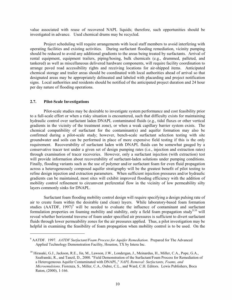
2.7. Pilot-Scale Investigations Pilot-scale studies may be desirable to investigate system performance and cost feasibility prior
to a full-scale effort or when a risky situation is encountered, such that difficulty exists for maintaining hydraulic control over surfactant laden DNAPL contaminated fluids (e.g., tidal fluxes or other vertical gradients in the vicinity of the treatment zone), or when a weak capillary barrier system exists. The chemical compatibility of surfactant for the contaminant(s) and aquifer formation may also be confirmed during a pilot-scale study; however, bench-scale surfactant selection testing with site groundwater and soils can be performed in place of more expensive field testing if this is the only requirement. Recoverability of surfactant laden with DNAPL fluids can be somewhat gauged by a conservative tracer test under a given set of design pumping rates (i.e., injection and extraction rates) through examination of tracer recoveries. However, only a surfactant injection (with extraction) test will provide information about recoverability of surfactant-laden solutions under pumping conditions. Finally, flooding variants such as the use of polymer and/or surfactant foam for even fluid propagation across a heterogeneously composed aquifer stratigraphy will be the greatest benefit of pilot testing to refine design injection and extraction parameters. When sufficient injection pressures and/or hydraulic gradients can be maintained, most sites will exhibit improved flooding efficiency with the addition of mobility control refinement to circumvent preferential flow in the vicinity of low permeability silty layers commonly sinks for DNAPL.
Surfactant foam flooding mobility control design will require specifying a design pulsing rate of
air to create foam within the desirable (and clean) layers. While laboratory-based foam formation studies (AATDF, 1997)9 will be needed to evaluate the influence of contaminant and surfactant formulation properties on foaming mobility and stability, only a field foam propagation study9,10 will reveal whether horizontal traverse of foam under specified air pressures is sufficient to divert surfactant fluids through lower permeability zones for the air pressures applied. Thus, a pilot investigation may be helpful in examining the feasibility of foam propagation when mobility control is to be used. On the
9 AATDF. 1997. AATDF Surfactant/Foam Process for Aquifer Remediation. Prepared for The Advanced
Applied Technology Demonstration Facility, Houston, TX by Intera Inc.
10 Hirasaki, G.J., Jackson, R.E., Jin, M., Lawson, J.W., Londergan, J., Meinardus, H., Miller, C.A., Pope, G.A., Szafranski, R., and Tanzil, D., 2000. "Field Demonstration of the Surfactant/Foam Process for Remediation of a Heterogeneous Aquifer Contaminated with DNAPL," NAPL Removal: Surfactants, Foams, and Microemulsions. Fiorenza, S., Miller, C.A., Oubre, C.L., and Ward, C.H. Editors. Lewis Publishers, Boca Raton, (2000), 1-166.
10

other hand, polymer addition for mobility control, particularly for removal of contaminants of greater viscosity than water, increases the viscosity of the flooding solution and will require higher induced gradients for capture of contaminated and remedial fluids. Pilot testing can determine whether the gradients necessary for capturing DNAPL and polymer-surfactant fluids can be maintained for improved contaminant contact and recovery compared to an unamended (without polymer mobility control) system. Similarly, if heating is deemed necessary to assist in mobilizing a viscous contaminant, pilot testing can assist in feasibility evaluations.
When intended only for a portion of the entire source zone area, a pilot-scale investigation
should occur ideally in the upgradient portions of the source zone area. This will ensure minimum disturbance of streamlines within the test zone caused by any existing containment pumping that can not be turned down, and protect the zone being flooded from subsequent recontamination by DNAPL outside of the treated zone to maximize the benefit of the pilot study remediation effort. As earlier mentioned, as much free-phase NAPL should be removed from zones adjacent to the targeted remediation zones as possible to facilitate meaningful collection of any post-treatment monitoring data, as well as for the longevity of remedial efforts. When inaccessibility issues arise, such as DNAPL located beneath a building in use, remediation efforts should consider hydraulic isolation of these zones. The above issues apply equally to a full-scale remediation that is performed in a modular fashion to reduce equipment capital costs.
11

Section 3.0: SEAR SYSTEM COMPONENTS
This section seeks to clarify the major equipment items in use with and components of in-situ surfactant flooding operations. Following the process design and initial planning stages, design operating parameters such as the durations of flooding phases (i.e., aquifer preparation flooding, surfactant flooding and post-surfactant water flooding), required chemical quantities, and individual well pumping rates, will be specified for a given estimate of DNAPL mass and distribution. Implementation of surfactant flooding remediation will require further engineering design and construction of the flooding system components to allow continuous delivery of enhancing or remedial fluids and recovery and handling of spent surfactant solution and contaminants. The sizing of field equipment may occur once the available capacity of on-site or vicinity wastewater treatment facilities has been evaluated and confirmed. It may thus be more feasible to address the source zone in sections proceeding from upgradient to downgradient portions as recommended, to reduce any treatment plant construction costs as well as the cost of any additional fluids processing to recycle surfactant chemicals. Administrative or management constraints may also influence the scale of flooding system construction activities. The major surfactant-enhanced flooding system components are introduced below. 3.1 Component Description
A SEAR project requires equipment and components to conduct the following major field tasks:
�� Preparation of surfactant solution and other injected chemical solutions; �� Injection and extraction operations; �� Monitoring of system parameters; �� Maintenance of critical system design parameters; �� Wastewater treatment.
The operational criteria for these tasks and their associated equipment, hardware and materials of construction where relevant (e.g., for chemical compatibility) are discussed in the sections that follow.
3.1.1 Chemicals Preparation.
There are in general three options for preparing chemical solutions for delivery on a SEAR
project:
�� Batch (tank) mixing; �� In-line mixing; and �� Pre-mixing or off-site preparation.
These options may be applied to the preparation of two types or compositions of solutions that are injected during SEAR flooding operations: surfactant solutions and water flood or hydraulic control solutions. Surfactant solutions are commonly comprised of a surfactant, salts of sodium and/or calcium, and a cosolvent. Occasionally, a polymer may be added as well. Water flooding and hydraulic control solutions consist of potable water mixed with the same electrolyte at the same or lower concentrations as used for the surfactant mixture, and will be referred to in further discussion as electrolyte solution.
3.1.1.1 Batch Preparation Method. Batch preparation methods are the most common method
of preparing chemical solutions in the field for small-scale surfactant flooding projects. Mixing conditions within tanks can be created with recirculation pumps that draw fluid from the bottom of the tank for discharge at the top of the tank. The tanks will require fittings for drawing fluids in this manner. To decrease the amount of time required to mix the injected batch, a mixing pump should be
12

obtained that provides for a flowrate capacity sufficient to ensure adequate time to prepare additional batches such that only well-mixed fluids, passing quality standards (to be discussed in Section 4), are delivered for injection. The viscosity and composition of the unmixed injectate must also be considered in selecting recirculation pumps for mixing. A pump and tank configuration is shown in Figure 3-1.
Fiberglass or composite plastic tanks can be used for blending and storage of the surfactant,
alcohol, and electrolyte solutions. The specification of the tank materials should be based on an evaluation of the chemicals that will be stored in the tanks to ensure that the tank materials are compatible. An array of high density polypropylene (HDPE) tanks used for blending electrolyte solutions is shown in Figure 3-1. Composite plastic materials are generally chemically compatible and resistant to most of the chemicals used on SEAR projects and are easier to handle when empty because of their relatively low weight. For mixing and storage of the injectates or solutions to be injected, multiple tanks will be necessary to allow for the injection of a mixed batch and the concurrent mixing of additional batches. A minimum of two tanks is recommended for surfactant preparation with one tank for mixing and the other tank for storage of the mixed solution. This ensures that sufficient injectate quantities are continuously available for injection. In general, the minimum capacity of the storage tanks should be at least 150% of the expected volume of chemical solution delivery. For injectate preparation on SEAR projects, tank volumes of 6,000 gallons or less, consisting of composite plastic materials are commonly used.
Figure 3-1. HDPE Storage Tanks Used for Blending Electrolyte Solutions Surfactant and cosolvent chemicals are usually delivered to the site in drums or in bulk tank cars
and will need to be transferred to tanks for batch mixing. The viscosity of most surfactants used in SEAR projects is in the range of 40 to 1000 centipoise (cP), (depending on the purity of the surfactant preparation from the manufacturer that can be variable), which is significantly more resistant to flow
13

than water that possesses a viscosity of 1 cp. When transferring viscous surfactants and surfactant solutions through hoses and tubing, additional head losses will be encountered, which should be accounted for in specifying the pumping capacity and line diameters. When transferring alcohol on-site, extreme caution must be taken to ensure that the pump type and construction materials do not create a flammable or explosive situation during the transfer process.
3.1.1.2 In-Line Mixing Method. To mix chemical solutions in-line, hydrodynamic mixers
installed in the injection line are used in lieu of batch mixing tanks and recirculation pumps. This method of mixing is an innovation derived from the food industry and requires less tankage than the batch mixing method for supplying high flow volumes of surfactant solutions and to accommodate relatively small footprints. In-line mixing requires that injectate components be accurately metered into a potable water stream so that the mixture contains the appropriate chemical concentrations. The chemicals are staged in relatively small tanks in pure form or high concentrations and then metered into the injectate stream for mixing at the hydrodynamic mixer. Properly selected chemical transfer pumps and flowmeters or metering pumps can be used for chemical metering. This method greatly reduces injectate mixing time, but relies heavily on the accurate metering and performance of the equipment items, which will be operated 24 hours per day during flooding operations.
3.1.1.3 Pre-mixing or Offsite Chemical Preparation. When it can be arranged with a
chemical manufacturer, pre-mixing of supplied chemicals may prove to be the most cost-effective option for preparing surfactant solutions. This will provide the most consistent quality of surfactant solution for flooding operations. Surfactant, cosolvent (if used) and electrolyte are pre-mixed at the vendor facility for delivery to the site. Electrolyte solutions for hydraulic control wells will still require batch mixing preparation. For premade solutions delivered to the site, the storage volume should be based upon the turnover or use of the chemicals with a storage capacity for a one-week or a one-month supply being desirable depending on the environmental stability of the chemical compound solutions to be stored.
3.1.2 Injection and Extraction Operations.
A simplified process flow diagram of injection and extraction operations with control
instrumentation is provided in Figure 3-2. Water injection or hydraulic control wells supplement extraction wells for maximum containment and recovery of injected fluids. Automated process control and data acquisition for continuously monitored pumping operations is addressed further in Section 3.1.4.
Injection and extraction operations require properly constructed injection and extraction wells
alongside standard equipment items that include injection and extraction pumps and controllers, flowmeters and a combination of hoses, tubing, pipes and valves for carrying fluids to and away from the treatment zone. In-line filters will be needed upstream of pumps and flowmeters to protect against damage and poor performance from particulate materials, such as any undissolved impurities from chemical solution tanks and soil fines removed from extraction wells. Reformulation of recovered surfactant fluids for reinjection may result in precipitation of iron and cationic species from solution and require additional filtration prior to reintroduction to the aquifer. Backup power generation equipment is suggested for continuous pumping operations, and pumping power hookup should consider minimizing the time to switch to a backup power source when a power-out alarm is sounded.
3.1.2.1 Injection and Extraction Wells. Proper well construction is perhaps one of the most
important, yet often poorly accomplished, aspects of addressing NAPL remediation. It is a major component in the success of a SEAR project, as maximizing the available pumping gradients is
14
15
Figu
re
3-2.
B
asic
Su
rfac
tant
Fl
oodi
ng
Com
pone
nts

critical to recovering contaminated fluids of elevated density and viscosity relative to water. For this reason, well construction methods used for SEAR wells, are more detailed and demanding than for conventional groundwater monitoring wells. Existing wells pre-dating discovery of DNAPL zones may best be used to supplement surfactant flooding operations as groundwater sampling and water level monitoring locations, as relevant.
Following SEAR design, the well locations and screen intervals and depths will be known and
well construction can begin. To ensure that well construction is consistent with the stratigraphy and contamination at the site, the following should occur:
�� Screen placement across the contaminated stratigraphy of interest. Furthermore, at
DNAPL sites, the bottom of the well screens in recovery wells should be installed across the lower capillary barrier/aquifer interface (this allows for uninhibited DNAPL migration into the well). At LNAPL sites, the screens should span the oil/water interface and be long enough to meet the demands of the SEAR design. Well construction should not allow cross contamination between aquifers.
�� Well screen and filter pack sizes should be properly selected based upon the particle size of the aquifer material.
�� Well materials should be chosen based on their chemical compatibility with the contaminant(s) and other SEAR chemicals as well as their physical compatibility with pressure or heat stresses that may be exerted.
�� Injection and recovery well screens should be continuous wire wrap (this improves well efficiency and allows for superior well development).
�� Wells must be accurately placed within the desired depth interval and not offset by conditions such as flowing sand.
�� Wells should be installed using centralizers to ensure placement in the middle of the borehole.
�� Drilling fluids should be selected that do not inhibit well development, thereby decreasing well efficiency.
�� The volumes used and placement of the sand/gravel filter pack should be carefully monitored to insure that the filter pack fully surrounds the well screen.
Detailed recovery well construction specifications intended for duplicate use in DNAPL site
characterization and surfactant flooding remediation were provided in the design manual and have been included as Appendix A within this document. Occasionally, wells installed during the DNAPL investigation phase are screened over the improper depth intervals, or demonstrate poor efficiency. If the well is screened to the appropriate final depth, it may still be used for mobile DNAPL removal, and perhaps for injection activities with the use of an inflatable packer to modify the screen interval as applicable. Wells that perform poorly during tracer injection or extraction activities should be redeveloped and replaced if feasible.
3.1.2.2 Pumps and Plumbing. With the completion of design simulations, the required
flowrates and head differential for establishing hydraulic control will be known. This information is used to select pumping equipment. The optimum pump configuration to maximize well fluid recovery uses dedicated extraction pumps for each well. When selecting downhole submersible pumps, such as those used frequently for recovery operations, consideration must be given to the diameter of the well, the number of pumping zones per well, the lift and flowrate required under maximum viscosity conditions, and the chemical compatibility of the pump materials with the effluent. In practice, even if the mobilization of NAPL is not anticipated during surfactant flooding, it is recommended to design for this possibility. As 24 hour per day operation will be required, equipment reliability will also be a
16
major criterion of all pumps selected. Finally, spare pumps should be readily available for contingency use.
The plumbing conduits of a SEAR system for injection and extraction operations include
pipes, tubing and hoses. Selection of appropriate materials, such as steel or polyvinyl chloride, should be based on factors including cost, pressure rating, and chemical compatibility with surfactant fluids and NAPL11 (in the recovery lines). Manifolding of injection or extraction lines requires piping material construction. Otherwise where possible, flexible tubing or hoses are more convenient for mobility and construction.
Valves are used to control the movement of fluids through pipes, tubing, and hoses, such as
for sampling fluids and flowrate measurement and control. Valve types used on a SEAR project include ball, gate and needle valves. Ball and gate valves are commonly used for on/off control of fluids, and can also be used for rough flowrate control. Needle valves are used for more precision in flowrate control. Valves that are electronically actuated will be required for automated flowrate and pressure regulation. As with other plumbing material types, cost, pressure rating, and chemical compatibility with fluids should be considered when selecting valve material types.
3.1.3 Monitoring System Parameters.
Monitoring equipment is used to collect data to gauge SEAR progress and to maintain and refine SEAR system operating parameters. Throughout a SEAR project, fluid chemistry, fluid flow properties and aquifer properties are regularly monitored. Table 3-1 shows the most important system monitoring parameters and common monitoring locations. For performance monitoring of a surfactant flooding operation, groundwater samples are most easily collected from extraction wells. However, groundwater samples collected at these locations will not provide vertical performance data. A multi-level sampler (MLS) network within the extraction wells can provide undiluted groundwater samples at depth discrete intervals, more accurately reflecting the capacity of the surfactant formulation and contact of discrete aquifer zones through a heterogeneous aquifer. Appendix B discusses MLS devices in further detail.
Specific conductance, temperature and pH can be measured with manually operated meters or
using in-line probes, particularly for process monitoring of effluent fluids. Flowrates and system pressure can be measured using calibrated in-line flowmeters and pressure instruments. Electronic pressure transducers or transmitters and manual water level meters can be used to determine the elevation of the water surface within and adjacent to the treatment zone.2,12 Interface probes can determine the in situ depth and corresponding volume of DNAPL within a well. DNAPL volume may also be determined using a graduated glass cylinder or similar device after pumping or bailing from a well. Sampling of monitoring points can occur either intermittently, whenever a sample is scheduled for collection, or continuously (i.e., with continuous pumping) at low flowrates. Intermittent sampling of wells or multilevel samplers is typically conducted using surface pumps, while continuous sampling
11 United States Environmental Protection Agency. 1995. Nonaqueous Phase Liquids Compatibility with
Materials Used in Well Construction, Sampling and Remediation. EPA/540/S-95/503. Technology Innovation Office. Washington DC.
12 United States Environmental Protection Agency. 1985. Practical Guide for Ground Water Sampling. EPA# CR-809966-1. Illinois State Water Survey Contract Report #374. Prepared in cooperation with Robert S. Kerr Environmental Research Laboratory, the Environmental Monitoring Systems Laboratory, Las Vegas, Nevada, and the Illinois State Water Survey.
17

Table 3-1. SEAR System Monitoring Parameters
Category Monitoring Parameter Monitoring Location
Fluid chemistry Temperature, pH Specific conductance Electrolyte Cosolvent Surfactant Contaminant (NAPL volume and dissolved concentration of each component)
Mixed injectate (tank or injection line), extraction wells and monitoring points(a) Extraction wells and monitoring points(a)
Fluid flow properties Pumping flowrates Pressure
All pumping locations Injection, extraction and wastewater processing fluid lines
Aquifer Properties Water levels Free-phase NAPL levels
Injection and extraction wells and monitoring wells Check for in all wells being monitored during flooding operations
(a) Refers to monitoring wells, multi-level samplers (MLS), and monitoring points for wastewater treatment processes
often utilizes submersible pumps. Low flowrate pumps such as peristaltic and bladder pumps are commonly used for sampling purposes. Sampling pumps, filter devices, tubing points and materials, as well as sampling well points, should be chemically compatible with NAPL in the aquifer.
Extraction well line sample retrieval can be accomplished using in-line sampling equipment
that can be electronically actuated. With appropriate well sampling accessories, in-line sampling devices can be used in tandem with autosampler equipment and gas chromatography (GC) components adapted for surfactant solutions and high organic compound loading to quantify cosolvent and solubilized contaminant concentrations. This type of system can provide near real-time concentration data for monitoring of multiple effluent lines. Monitoring of surfactant concentrations, such as for maintaining injectate quality and performance capabilities of wastewater treatment processes, will require titration or HPLC equipment. Alternatively, a surrogate organic compound, such as the cosolvent co-eluting with the surfactant, which requires only appropriately fitted GC equipment for measurement, may be used to estimate surfactant concentrations. Analytical methods are discussed in Section 4.2.3. Surfactant titration equipment is detailed further in Appendix C.
18
3.1.4 Process Control System. Due to the extent of data collection activities for system monitoring on SEAR projects,
automated data recording devices are suggested. Electronic monitoring equipment for injection and extraction operations can be incorporated into a data acquisition system (DAS) for automated data logging and feedback process control. A centralized user interface may be attached for data access and viewing. Such is known as a Supervisory Control and Data Acquisition system (SCADA). A SCADA system for SEAR incorporates electronic monitoring and control devices for automated measurement and regulation of flowrates, system pressure, water levels and other parameters as desired. An assembly of SEAR components that includes SCADA control features is displayed in Figure 3-2. Aboveground treatment operations will typically require separate control systems and displays for different monitoring features.
System software is used for interactive control of SCADA components and must be
customized for each project to address the site-specific number of items such as injection wells, extraction wells, sampling parameters and sampling frequencies. Automatic shut-off devices and alarming features may also be incorporated with the inclusion of a SCADA system. Most SCADA components are integrated within a system control trailer that is plumbed to injection and extraction lines. Although a SCADA system will still require periodic calibration using manual measurements and more hardware to assemble, there can be a significant reduction in the labor requirements that attend 24-hour field operations. Continuous system monitoring will generate a much higher volume of data for SEAR documentation and performance evaluation, and this data can be efficiently collected and viewed in electronic format.
3.1.5 Wastewater Treatment.
The principal unit operations for a SEAR wastewater treatment system and selection criteria,
including commercial availability of separation systems developed and tested for surfactant/cosolvent flooding wastewaters, are described in the design manual. Technologies for contaminant removal may include conventional processes such as air-stripping and steam-stripping, or innovative processes such as liquid-liquid extraction and pervaporation, depending on surfactant chemical recovery requirements and contaminant effluent properties. Once the bulk of strippable or contaminated compounds are removed, biological treatment may be used with a sufficient residence time for surfactant degradation. However, more typically, surfactant may be allowably discharged (under permit) into another off-site wastestream, and as such it will often contain foam suppressing chemicals; on the other hand, it may also be concentrated for reuse on-site by filtration and foaming methods both necessitating the absence of foam suppressants.
In addition to aqueous-phase organic compound removal equipment, pretreatment and
auxiliary equipment will frequently include:
�� Decanting equipment (or separators) to remove free-phase NAPL; �� Chemical metering equipment to adjust pH and dispense antifoaming agent; �� Surge/Process storage tanks; and �� Contingency storage tanks.
A UV sterilization or chemical amendment unit to destroy microorganisms in the process water may be necessary if biofouling is anticipated to adversely affect the treatment process. Similarly, additional filtration devices may be required to capture suspended particulates (i.e., fines and precipitates) that may cause fouling of thermal treatment lines and membrane modules when used.
19

Bag filters (i.e., 1 to 25 �m filters)13 are effective in removing such particulate matter without pressure drop concerns. Appropriately rated pumps will be required to move fluids from one process unit to another. Plumbing networks of piping, tubing and hoses with valves and gauges of compatible and process-rated materials will provide controlled fluid movement throughout the system.
Additional tankage to accommodate possible system modifications (such as increased
pumping rates) as well as effluent streams which fail discharge permit limits should be readily available. For surge/process storage tankage, chemically compatible thermoplastic storage tanks can be used once DNAPL is mainly removed. Metallic or stainless steel tanks and drums are commonly used for storing DNAPL fluids. For contingency tankage, oil-field frac tanks or tractor-trailer tanker trucks are generally used given their larger capacities, rental availability, and trailer mobility. Secondary containment will be necessary for tanks and plumbing containing chemical solutions, as further discussed in the next section. As shown in Figure 3-3, wastewater treatment equipment may be contained within a tented facility with plumbing to wastewater discharge tankers, including bypass hosing to the tankers for emergency operations. Containment lining can be constructed during tent installation using wood berming about the perimeter of the tent frame to elevate the flooring edges of an appropriate liner material.
Figure 3-3. Temporary Tented Wastewater Treatment Facility
13 Vane, L.M., Hitchens, L., Alvarez, F.R., and E.L. Giroux. 2001. “Field demonstration of pervaporation for
the separation of volatile organic compounds from a surfactant-based soil remediation fluid.” Journal of Hazardous Materials, B81 (2001), 141-166.
20

3.2 Systems Components Preparation
During system mobilization and assembly, some components will require calibration, leak and failure checking, and conditioning against inclement weather and potential system failures. Appropriate calibration and testing equipment will be needed to maintain operability of pumping equipment and data logging devices both within specified ranges. Components that fail calibration testing should be repaired or substituted prior to initiating flooding operations; this applies particularly to commonly rented equipment such as water quality measurement probes and pumps. If used for on-site operations, GC equipment, i.e., detectors, and any transducing equipment, such as actuated sensors and other automated devices, will also require calibration. Health and safety instruments, such as a combustible gas indicator, should be periodically calibrated prior to use.
Flowmeters and metering devices can be calibrated by taking an average of several manual
flowrate or fluid delivery measurements (e.g. bucket tests). Of particular importance is that the flowmeter be rated for the viscosity of the fluid it is intended to monitor and that the fluid being monitored itself is used during the calibration process. Water quality probes and pressure transducers should be calibrated in accordance with the manufacturer’s guidance. Pumps should be individually checked for leaks and malfunctions. Potable water should be used to test system components for proper flow routing and leaky connections. Flow-related devices should be tested at the highest and lowest anticipated flowrates to verify that all valves, flowmeters, pressure gauges, and plumbing will operate as designed and not malfunction.
Some equipment may require protection from inclement weather to avoid unexpected system
failures and operational complications. Pumps and other outdoor electric equipment should be weatherized (with appropriate covers) and be properly grounded with ground fault interruptors (GFI). Sensitive electronic equipment should be safeguarded against exposure to heat, light and moisture and be equipped with properly conditioned power sources where relevant (e.g. GC equipment). Any SCADA and DAS components should be equipped to minimize the impact of potential power interruptions.
Tank storage areas will require secondary containment that can hold a volume equal to 110%
of the largest tank contained, unless otherwise stipulated by local regulatory authorities. High density polyethylene (HDPE) landfill liner can be used to construct most secondary containment. Experience has shown that the HDPE liner should be at least 20 mils thick and of the ‘cross-linked’ variety. For effluent tanks, it should be noted that HDPE is not compatible with chlorinated solvents, but there are few acceptable materials that can be otherwise used. Sheets of plywood can be laid over or under the liner to reduce puncturing. The walls of the secondary containment system are often constructed with straw bales or with fencing materials. A secondary containment liner is shown in Figure 3-1. Site drainage should be directed away from wells and drum storage areas as much as possible using appropriately constructed drainage diversion and/or collection systems.
21

Section 4.0: FIELD OPERATIONS
This section discusses surfactant flooding operations, beginning with startup of the fully assembled system. Detailed procedures have been provided below for chemicals preparation, inclusive of quality control procedures, monitoring operations and analytical methods. With wellfield installation, free-phase DNAPL may be indicated in additional wells, and DNAPL recovery operations must occur to evacuate as much DNAPL as feasible prior to surfactant injection activities. Depending on the duration of free product removal required, some of these activities, such as water flooding, may be coordinated with other SEAR aquifer preparation activities (as described further in this section) or any additional tracer testing recommended during groundwater pumping (i.e., extraction) activities, once it is deemed safe to inject fluids under pressure.
4.1 System Initiation
During the initiation of operations (injection and extraction), the objectives are to establish the
flow field and to verify the system integrity and stability. Pre-remediation verification of system equipment requires startup of the effluent treatment system. Specific tasks include:
�� Rechecking the system for leaks and adjusting flowrate equipment operation under
actual system pressures; �� Verifying that hydraulic control of injected fluids has been established; �� Ensuring that the effluent treatment system is functioning properly and permitted
discharge limits are being met; �� Testing the accuracy of all automated data recording and display features of any data
acquisition system; and �� Testing alarms and automatic equipment shut-off features.
System testing should continue until all of the injection and extraction rates and water levels are stable, indicating that the flowfield has been established, and at a minimum a pore volume of water flooding solution has been delivered through the treatment zone.
4.2 Flooding Operations
Surfactant flooding operations can begin once the system operation is stable. In total, there
are three stages of surfactant flooding operations. The first stage is to establish the flow field and aquifer preparation for surfactant injection. An electrolyte solution that will not induce permeability reduction due to soil ion exchange interactions, is injected to prepare the aquifer for optimum performance of the surfactant. (Additional details on the influences of electrolyte upon anionic surfactant behavior and soil minerals can be found in the SEAR Design Manual.) The second stage is to flood the targeted treatment zone with the surfactant formulation. The surfactant solution designed for the site contaminant and soils is delivered to the treatment zones to enhance the removal of contaminants. The final stage is to remove the injected surfactant solution chemicals and associated DNAPL. Water is injected to continue the movement of the surfactant solution with the solubilized and/or mobilized contamination through the subsurface to the extraction wells for recovery. An electrolyte may still be added to the injectate during this period to maintain optimum aquifer conditions for continued flooding.
22

4.2.1 Injectate Preparation and Quality.
4.2.1.2 Surfactant Injectate Preparation. When preparing surfactant solutions by either batch or in-line mixing, the electrolyte (calcium or sodium chloride) must be dissolved in water before the surfactant is added. Otherwise, the surfactant may not remain soluble in solution when salt is added. Cosolvent is best mixed in following surfactant, as it will assist in removing any residual surfactant from transfer lines and pumps. As a rule of thumb, a surfactant batch should be prepared with the following sequence:
1. Partially fill the mixing/holding tank with potable water; 2. Add the amount of salt required for the total batch, mix until all salt is dissolved; 3. Add the required amount of surfactant to the tank; 4. Add the required volume of cosolvent (if applicable) to the tank; 5. Fill tank to the desired volume with potable water; 6. Continue to mix the contents. When transferring flammable chemicals such as cosolvent, the drums or other metallic
containers as well as all equipment items used should be grounded to reduce possibility of a static discharge. Appropriate personal protective equipment (PPE) should also be used when handling these materials. It is important to keep tanks and piping clean to avoid fouling or plugging of the chemical lines. Solutions with high alcohol content should be stored and handled appropriately to avoid any chemical hazards.
4.2.1.3 Injectate Quality Control Measures. The simplest method of verifying the quality of
a surfactant solution is to perform phase behavior testing of the surfactant solution in the field. The purity of surfactants, i.e., active wt%, as supplied by the manufacturer, may vary with shipment, so phase behavior trials should be conducted with the mixed injectate before it is injected. For batch mixing, samples should be taken from the top and bottom of the tank of each surfactant batch to confirm that the solution is uniformly mixed. For in-line mixing, routine sampling of the downstream injectate concentration should be used for verification. The phase behavior test will demonstrate whether the surfactant chemicals have been mixed in the proper quantities and detect any variability in water hardness that may affect surfactant performance. Equal volumes of the mixed surfactant injectate and preferably site (D)NAPL are combined in a sealed pipette, and the equilibrated pipette can be compared to laboratory phase behavior standards. A detailed description of the interpretation of phase behavior testing results is given in the SEAR Design Manual. Phase behavior tests are usually supplemented with chemical analyses for surfactant, alcohol and electrolyte for precise information on the surfactant injectate composition. With sufficient batch tank storage capacity, quick-turn around analytical results will allow for unsatisfactory mixes to be adjusted. Any surfactant recycle activities will require analysis of the recovered surfactant solution for amendment, and preferably analysis of the amended surfactant solution, including residual contamination concentration, prior to reinjection.
When analyzing water flood or hydraulic control injectate mixture for uniformity, the specific
conductance of the mixture is commonly used to verify uniform mixture of the added salts. The conductivities obtained from the top and bottom samples will not vary by more than 10% when adequately mixed. For conductivity measurements within surfactant batches, the measurement will require calibration to a surfactant mixture containing the correct salt concentration. In this way, a determination of the salt content and homogeneity of the surfactant batch mixture can be made.
23
Finally, it is important to maintain a log of the mass quantities of injected chemicals. A detailed account of the quantity (volumetric and/or weight measurement) of all chemicals added to each surfactant batch or staged in tanks for in-line mixing should be recorded in a field logbook or on uniform field forms and compared to the expected quantities as determined from the design. Flowrates of metering devices used for in-line mixing should be confirmed periodically as well. In all, these procedures will help ensure that the correct mass/volume of the specific chemical has been meted out before mixing. Records should also be kept on the chemical composition of the injectate as reference information to maintain fluid quality.
4.2.2 Monitoring Evaluation of Flooding Operations.
System monitoring is necessary to maintain control over injected fluids and to track the
progress of the remediation effort. The data collected is used to adjust system performance as needed. Pumping flowrates and treatment duration are typically constrained by the available head with drawdown at the recovery wells, bulk chemical cost and field budgets. As described in the SEAR Design Manual, multi-phase fluid flow design simulations conducted with appropriate design data can provide estimates of flooding duration required to meet a given budget and specified target remediation goals. For reasons of cost, performance monitoring will usually not dictate flooding duration, except with real-time performance data and flexible contracting to allow immediate extensions in surfactant flooding duration and any concomitant increases in post-water flooding duration. Common debugging issues in field implementation that require system monitoring include: errors in chemical purity and surfactant formulation preparation, failure to maintain adequate injection or extraction rates, unexpected aquifer conditions and data gaps (e.g., incomplete stratigraphic data leading to poorly chosen well construction materials and unstable performance).
4.2.2.1 Flowrate, Water Level and DNAPL Level Monitoring. Once surfactants have
been injected, frequent monitoring of the system is usually undertaken to maintain hydraulic control of the swept zone, even if conducting the source removal from within a barrier wall. If hydraulic control of the treatment zone is not maintained, the swept areas intended for treatment may not be effectively flushed and the recovery of the surfactant/NAPL mixture may be lower than anticipated or required. Regulating injection and recovery flowrates is vital to maintaining hydraulic control. The magnitude of the injection and recovery flowrates will govern the rate at which the surfactant solution is transported through the subsurface as well as the size of the aquifer pore volume that is swept by the surfactant solution; therefore, hydraulic control can not be maintained simply by turning down injection flowrates without altering the duration of the surfactant flooding operations and possibly the volume of the treatment zone. The flowrates should be monitored as often as practical at each of the injection and extraction wells, and at any hydraulic control wells. Adjustments to the flowrates can then be made on a timely basis if they are out of the specified design range.
Flowrate monitoring is accomplished most simply by basic manual ‘bucket’ tests with a
graduated container and timer. However, manually-read volumetric totalizers and timers or manually-read electronic rate meters can also be used. Electronic flowmeters and a DAS may be most convenient for constant flowrate monitoring, but electronic flowrate equipment will require regular calibration against manual measurements. With the capability of electronic monitoring and alarm system with off-site notification procedures, hydraulic control of the flow field can be closely monitored around the clock to ensure the source zone is effectively swept and that the recovery of the injectate and NAPL is maximized.
With improperly formulated surfactant injectate or poorly designed surfactant solutions,
permeability reduction can sometimes result. If injection/recovery flowrates are continued in the
24

presence of permeability reduction, water levels will rise in the injection wells and fall in the recovery wells. An off-calibration pump or inclement weather may result in an increasing water level in a recovery well. Frequent water level monitoring can immediately detect such situations so that they can be corrected. More complex situations may be introduced in the presence of tidal fluctuations or other vertical groundwater gradients. Therefore, diligent monitoring of water levels influencing the SEAR capture zone may also be responsive to fluctuations in the field environment.
Manual monitoring by standard metered contact tapes is the most common method of
recording water level data. However, in order to capture a meaningful hydrostatic pressure surface map, a sufficient number of wells must be simultaneously monitored for water levels with each round. Ideally, water levels are simultaneously measured in as many well as possible, inclusive of injection, extraction, hydraulic control and surrounding monitoring and pumping wells. Electronic transducer measurements amplify the quantity of water level data that can be collected simultaneously. However, electronic sensing will require regularly scheduled manual measurements to ensure that the pressure transducer or transmitter is measuring accurately.
Electronically recorded flowrate and water level data should be checked regularly to ensure
that the data is being recorded properly and that the specified monitoring frequencies are maintained. Flowrate and water level data should be plotted regularly to note any trends. Gradual or abrupt changes in water levels that are not intended can provide information on changing subsurface conditions or system malfunctions. Offtrending flowrates may indicate equipment malfunction or off-calibration. Maintaining a constant watch on water levels and flowrates can alert site personnel to potential problems to be handled in a timely manner. A potentiometric surface map derived from plotting water level data collected during a surfactant flood is shown in Figure 4-1. Plotting water level data can demonstrate hydraulic closure of orthogonal streamlines, i.e., the direction and path of water flow is assumed orthogonal to the hydrostatic pressure gradient. It should be compared to monitoring well sampling results to verify that injected fluids are being captured.
Finally, as discussed in Table 3-1, free-phase NAPL levels should be recorded in all wells
being monitored. Simultaneous measurement is not as critical, and manually operated interface probes are typically used for this purpose. These measurements will provide an indication of the extent to which the surfactant solution is mobilizing DNAPL as a separate phase, and/or the efficiency of the hydraulic system in capturing free-phase DNAPL. When not under the influence of sufficient hydraulic gradients for removal, such as DNAPL accumulating in wells (i.e., well screens and/or sumps), bailing or pumping of these wells individually should be undertaken as immediately as possible.
4.2.2.2 Effluent and Monitoring Well Sampling. Sampling of SEAR fluids is conducted
to track the progress of injected fluid and DNAPL fluids during flooding operations. The primary monitoring points are the extraction or recovery wells and/or multi-level sampling points located just inside the target treatment area. Secondary monitoring points are monitoring wells beyond the SEAR wellfield. Effluent sampling of the target treatment zone, that includes the extraction well lines and near-extraction well monitoring points (wells or multilevel samplers), provides real-time information on the effectiveness of the surfactant flood in removing contaminant based on visual and quantitative evidence of surfactant progress through the aquifer. Ultimately, mass balance data will be obtained for the contaminant(s) and each chemical injected into the aquifer. Monitoring well sampling adjacent to the SEAR wellfield provides additional verification that containment of SEAR fluids is being accomplished when no sudden increases in the concentrations of injected fluids or solubilized contaminants beyond steady-state values are observed. Effluent and monitoring well sampling documents system performance, can be used to shift pumping gradients to the portions of the aquifer
25

Potentiometric Surface During Surfactant Flooding Operations
Figure 4-1
Figure 4-1. Potentiometric Surface Map of Water Levels During Surfactant Flooding Operations
26

Lower zone
Day 1 Days 13-18Days 3 - 122first 12 hrs
Upper zone
to
Start SurfactantInjection
End SurfactantInjection
Figure 4-2. Visual Monitoring Samples Collected from a SEAR Pilot Test
that require further remediation, as well as to improve hydraulic control performance, and may dictate the duration of flooding phases when initial DNAPL estimates are undeterminable. With effluent sampling activities, a relatively large number of samples will be necessary, given the number of sampling locations and analysis parameters. A mass balance comparison metric requires quantification of the mass of surfactant and cosolvent recovered from the subsurface. A determination of the DNAPL mass recovered will similarly require solubilized contaminant mass estimates to be obtained, in addition to the quantity of any free-phase product recovered (mobilized). To obtain an accurate mass recovery curve, approximately thirty samples is usually sufficient, although under tidal fluxes and to meet higher resolution data requirements, continuous monitoring is recommended. When the risk is lower (e.g., LNAPL sites), fewer samples may be collected with proper sample spacing that captures the peak breakthrough curve and tailing concentrations caused by post-surfactant water flooding. UTCHEM design simulation data can assist in developing an appropriate sampling strategy. Mass breakthrough curves based on each sampling location will provide detailed resolution on the subsurface distribution of surfactant solution and the spatial distribution of DNAPL recovery, to include vertical profiling when MLS devices are used. The impact of any hitherto undetected heterogeneities can be determined to correct operating parameters (such as foam addition parameters). Monitoring well samples collected for the purpose of monitoring hydraulic control should be maintained at a lower frequency, but should preferably accompany any change in an individual well pumping rate or with a change in flooding phase. In either circumstance, monitoring sample collection should span the entire flooding duration to reflect conditions prior to and following surfactant flooding. This includes monitoring locations within and beyond the contaminated aquifer.
Visual inspection of treatment fluids or effluent samples can provide real-time qualitative
information on when the breakthrough of surfactant mixture has occurred at the extraction well or intermediate sample recovery locations which can then be compared to the designed predictions. Figure 4-2 shows a set of near-extraction well monitoring samples taken at various time intervals during a pilot
27

test conducted to remove a high viscosity NAPL (1000 cp at 23 degrees C), Navy Special Fuel Oil, from two contaminated zones of the aquifer with surfactant solution heating. The procession from light to dark back to light indicates the breakthrough of surfactant solution with contaminant. Indicators of poor surfactant sweep efficiency across (D)NAPL zones can be evident within the first pore volume of surfactant flooding, if not by visual samples and observations at the extraction wells, then by verification of analytical concentrations at extraction wells. Analytical concentration data for contaminants and chemicals in the surfactant solution may be compared to design simulation predictions, allowing for immediate adjustments or corrections to the makeup of the surfactant formulation as required. In the flooding of a layered permeability saturated zone, poor sweep efficiency may not be readily detected unless multilevel sampling devices are used. Appendix D provides examples of comparison data with a discussion of modeling issues.
A variety of methods can be used for sampling and analysis. An auto-sampling system is usually
preferred, given the large number of samples to be collected for sample analysis. Sampling procedures should be developed which will ensure the integrity of the samples taken and the subsequent sample analysis. When samples are downloaded from auto-sampling systems, care must be taken to ensure that the samples are properly labeled and that sample control logs and chain of custody forms are correctly filled out.
Experience has shown that continuous low flow sampling of aquifer monitoring locations
generally results in less variation in concentrations sample to sample, producing a much smoother data set of concentrations versus time. The recommended monitoring sampling procedure is to push the sample to the surface using either a downhole pump such as a bladder pump, which does not allow the driving air to contact the sample or a tubing/check valve configuration that achieves the same end. This avoids common issues associated with suction pumping of surfactant-laden samples that includes sample foaming and volatile losses of contaminant and cosolvent. Intermittent samples may be acceptable for low frequency sampling of groundwater outside of the swept treatment volume where low surfactant concentrations may be anticipated. This will reduce the requirement for dedicated sampling pumps but will increase required decontamination activities; therefore, the cost requirements of each approach should be considered alongside the benefits of each sampling technique.
As mentioned in Section 3.1.3, equipment is available for automated sampling and in-line GC
analysis. Back up samples should be collected at a lower frequency and stored under required conditions in case of GC malfunctions. A minimum 40 milliliter (mL) aqueous sample volume should be collected for surfactant titrimetric analysis; carouseled automated high volume sampling devices can assist in avoiding sampling redundancy in this endeavor. Analytical methods used in SEAR are described in Section 4.2.3.
4.2.2.3. Wastewater Treatment Monitoring. Wastewater treatment monitoring is conducted to
confirm that contamination levels stipulated under regulatory permits for air and wastewater discharge are being met, and that violations are not impending with in specification wastewater treatment system operation. Gravity separator monitoring will also provide information as to the extent of DNAPL mobilization being effected by subsurface treatment operations. More heed to system parameters and sample collection will be needed at peak surfactant concentrations, which should coincide with peak concentrations of contaminant and cosolvent (the latter if used). Improper handling of surfactant-laden wastewater streams can cause serious operational difficulties such as poor contaminant removal efficiency, foam leakage from the system, and in the worst case, complete shutdown of the wastewater treatment system. Common system monitoring parameters include: temperature, pressure, flowrates, and pH, all in addition to tracking contaminant removal efficiencies frequently. Predicted effluent composition data from numerical design simulations as well as any bench- or pilot-scale testing data may assist with monitoring operations.
28

4.2.3 Sample Analysis. Various laboratory techniques currently exist and have been used for the analysis of
concentrations of surfactants, contaminants, cosolvents and electrolytes in recent field projects.4,14 However, the presence of all these components in a single phase makes accurate detection and quantification difficult. This section briefly discusses laboratory techniques required to analyze injectate and effluent samples during surfactant flooding. Available methods exist for surfactant identification within organic-rich fluids, and organic compound analysis within surfactant-rich effluents.
4.2.3.1 Surfactant Analysis. Techniques for the analysis of surfactant concentrations are
described in detail in current literature (Schmitt, 199215; Cullum, 199416). The potential techniques include potentiometric titration, HPLC (high performance liquid chromatography), evaporative light scattering detection, and ultraviolet or fluorescence detection.
Potentiometric titration is perhaps the simplest method to use for contaminated surfactant-laden
groundwater samples. Surfactants typically used in SEAR are alcohol ether sulfates, alkane sulfonates, and sulfosuccinates. To determine anionic surfactant concentrations by potentiometric titration, one precipitates the surfactant with a cationic surfactant titrant. An electrode combination that responds to anionic surfactant in solution serves as an indicator. The indicating electrode is a combination electrode pair consisting of an Ag/AgCl (silver/silver chloride) reference cell and a PVC membrane cell. A nitrate or sulfate sensing electrode may be used for sensing anionic surfactants. A dilute solution of benzethonium chloride (hyamine) is used as the titrant. The titrations should always be evaluated using the inflection point of the sigmoidal titration curve, which corresponds to the reaction equivalence point. This should preferably be done with an autotitrator or a pH meter capable of measuring potential and a burette. Typically buffering is not recommended for solutions with near neutral pHs. However, if the pH of the effluent is either acidic or alkaline, buffering is highly recommended. The exact hyamine titration technique should be tailored for each surfactant by running test titrations with known standards. An example of the hyamine titration technique to determine the concentration of sodium dihexyl sulfosuccinate is given in Appendix C.
HPLC techniques can provide more detailed resolution for surfactants with numerous isomers and
can be applied to detect uncharged impurities in an anionic surfactant mixture. They are generally more robust, but may require greater skill to implement. The stationary phase in the HPLC column should be compatible with the surfactant being used and identifying an optimal organic mobile phase for a specific surfactant formulation in a contaminated solution will require methods development. With a conductivity detector, the possibility of interference caused by miscellaneous solubilized ions and contaminants that can co-elute with the surfactant should be addressed during methods development. The presence of dissolved humic matter may interfere with light scattering and UV and fluorescence HPLC detectors.
Both the hyamine titration and the HPLC techniques can detect sulfate surfactants down to 0.01
weight percent. The titration techniques are generally much easier to perform and interpret and require less time for equipment setup and methods development. HPLC techniques may be used to assess surfactant degradability and impurity issues that may be relevant for surfactant flooding. 14 U.S. Environmental Protection Agency. 1999. In Situ Enhanced Source Removal. EPA/600/C-99/002. Office of
Research and Development, National Risk Management Research Laboratory, Subsurface Protection and Remediation Division, Ada, OK.
15 Schmitt, T.M. Analysis of Surfactants. Surfactant Science Series, Vol. 40; Marcel Dekker, Inc., New York, 1992. ISBN 0-8247-8580-2.
16 Cullum, D.C. (Ed.). Introduction to Surfactant Analysis. Blackie Academic, London, 1994. ISBN 0-7514-0025-4.
29

The methods detailed above are generally useful for surfactant detection within aqueous samples
containing other organic compounds. When cosolvent is not used in the surfactant formulation, simple methods that may be used for surfactant detection include examination of the foaming nature and interfacial tension properties of a liquid sample. Foam suppressing compounds and any other IFT reducing agents present will interfere to some extent with these methods.
4.2.3.2 Analysis of Organics in the Presence of Surfactants. The quantification of organic
contaminants such as solubilized tetrachloroethylene and trichloroethylene during SEAR is complicated by the presence of high cosolvent and surfactant concentrations. Surfactants can plug capillary columns, whereas high cosolvent concentrations generally overwhelm capillary columns and cause problems such as carry over. The preferred technique is to use a column that can take high sample loading and exhibit minimal plugging due to surfactant. Surfactant plugging can also be minimized with use of a precolumn, but such a device can cause greater dispersion and spreading of the sample peaks. Under these conditions, a modified EPA Method 8021B can be used to detect chlorinated VOCs and cosolvent using the flame ionization detector (FID). In general, this approach uses a packed stainless steel or glass column with direct injection onto the column using an autosampler (connected to in-line sampling device) and autoinjector. The advantage of using a packed column is that it can take much higher sample loading and the effects of surfactant plugging are usually not observed until after the injection of more than 300 samples or so. This technique is suitable for detecting PCE and TCE between 50 and 10,000 mg/L and cosolvent between 0 and 0.5%. Higher cosolvent (between 1% and 18%) and contaminant concentrations (between 10,000 mg/L and 50,000 mg/L) may be quantified using a thermal conductivity detector (TCD) in series with a FID. Using this setup, contaminant concentrations between 50 and 10,000 mg/L, and cosolvent concentrations between 0 and 0.5% will be quantified by the FID. The higher cosolvent and contaminant concentrations will be quantified using the TCD.
An alternative to addressing the presence of surfactant in contaminant samples is to use a purge
and trap method of sample injection. This technique is useful when a range of halogenated and nonhalogenated compounds are being detected, such analysis of VOCs by EPA Method 8260. Significant sample dilution is required as well as the addition of anti-foam agent to avoid surfactant foaming problems. Therefore, this technique may not be economical for handling large sample volumes that may result from a short duration surfactant flood. It is most simple to use for monitoring well samples beyond the treatment zone and when organic compound concentrations lower than 50 mg/l are anticipated.
4.2.3.3 Other Sample Analysis. To accurately quantify the concentration of divalent and metal
cations in extracted surfactant solutions, chemical analysis is necessary. It may also be necessary to confirm the sodium or calcium concentration in the injected solution after conductivity measurements are taken. This should be done using an inductively coupled plasma (ICP) detection technique such as EPA Method 6010B. ICP techniques are extremely robust, detect the total cations in solution (e.g. Fe,Mn,Cr ), have few interference problems from other cations, and show linear calibration curves through several orders of magnitude. 4.2.4 Equipment Maintenance.
The following maintenance checks should occur on a frequent basis during the operation of the
SEAR flood. These checks provide information about flow conditions and impending system failures and are listed below in approximate order of importance.
�� Check graphical or numerical data displays (e.g., pressure, flowrate, conductance) on the
SCADA and DAS systems if such capability is being used. This is an efficient way of looking at the behavior of numerous system components in a short amount of time.
30

�� Check all of the tank levels to avoid low level tank pumping and any overfull waste tankage.
�� Check flowmeter readings on injection and recovery systems to verify flowrates are within the desired ranges.
�� Check temperature and pressure gauges to see if readings are within desired ranges. �� Check for water or air leaks. �� Check for unusual noises (especially with pumps or sticky solenoid valves or
flowmeters). �� Check the placement of well covers and when raining, sandbag as necessary to prevent
sediment and debris from entering wells. �� Clean or replace all filters, particularly those on recovery and injection lines. �� Compare transducer readings to manual water-level measurements taken with a water-
level probe. If the two do not compare favorably to one another, the transducer should be adjusted, recalibrated, or replaced.
�� Check for frayed or damaged electric cords and loose connections.
Flowmeters should be checked periodically for accuracy by performing bucket tests. This will ensure that flowmeters remain calibrated to within specified limits (such as ±10%). Flowmeters that are found to be out of range due to drifting or damage can be recalibrated or replaced as needed. Each downhole meter or probe should always be calibrated before use. If readings drift or are erratic, a probe may require replacement. The owner’s manual should be consulted when troubleshooting or calibrating a meter.
Besides daily checks, some other system components need periodic checks during a SEAR flood.
Whenever necessary, in-line injection filters should be cleaned or replaced, particularly if pumping from a near-empty tank. Conditions where high particulate contents are produced or where free-phase NAPL is frequently present will require frequent filter maintenance. Scaling or solids buildup may occur with some system components during the course of the SEAR. This usually occurs where components are exposed to oxidation during the surfactant flooding operations or where the orifice size is reduced, such as at valves. Valves that have suspected solids buildup should be replaced with backup valves. The valve requiring replacement can often be restored to optimum working condition by soaking in a weak acid solution to remove the scaling.
When calibration parameters are changed or a component is replaced, the corrective action and
the time of action should be noted in the field log so that corrections to data can be made if applicable. Additionally, any parts that are replaced should be noted so that spare parts of critical components are always immediately available.
4.3 System Shutdown
Typically, shutdown of a surfactant flooding operation is based upon the conclusion of post-
surfactant injection water flooding to remove residual injected chemicals and contaminants from the aquifer. The duration of surfactant flooding and other flooding phases is based on initial DNAPL estimates, and multi-phase flow modeling with input of surfactant, hydrogeological and (field-)validated pumping parameters. Operating durations for a well-designed surfactant flooding system are often very short relative to alternative approaches that use vapor extraction contaminant recovery systems. With a properly designed and installed surfactant flooding system for aggressive DNAPL recovery (referred to as high performance design in Appendix E), long flooding durations (i.e. greater than 2 months) are not usual. If not demonstrating effective DNAPL recovery during this period, significant redesign is necessitated. Thus, system shutdown can occur once significant quantities of injected chemicals have been removed from the subsurface during post-surfactant injection water flooding. Unless surfactant has
31

become sorbed to the point where reduced aquifer permeability makes further DNAPL pumping impossible (i.e., disastrous failure of surfactant formulation design), surfactant-laden fluids will always require removal from the aquifer. In general, if hydraulic control over the treatment zone is maintained, it is recommended that DNAPL pumping be continued until asymptotic dissolved-phase concentrations have been maintained for several fluid pore volumes to capture the majority of surfactant and cosolvent before the system is shutdown. Elevated dissolved-phase concentrations measured while injection and extraction pumping of the flooding wellfield is still maintaining hydraulic capture (e.g., exceeding the 1% rule of thumb) is indicative of a residual DNAPL saturation in the treatment zone or swept pore volume, but concentrations should in all cases (excepting disasters) be measurably lower than the initial dissolved concentrations observed. The permanence of such a concentration reduction will depend upon lack of recontamination, particularly absence of free product intrusion, from adjacent untreated zones; therefore, a repeat reminder to evacuate free-product DNAPL from all portions of the source zone prior to surfactant flooding operations.
The primary task during system shutdown is to decontaminate system flow components,
particularly effluent pumps and lines carrying contaminated groundwater, while still interconnected. This typically involves pumping a decontamination fluid through these lines. When disassembling system equipment and plumbing, leaving elements of the treatment system in place as long as practical to treat the decontamination fluids developed may be cost effective. Precautions must be taken to contain any fluid release from the system as it is being disassembled. Installing valves at the ends of runs of tubing or piping during the initial assembly process will allow the sections of hose/pipe to be removed with both ends closed to facilitate control of the fluids contained within. Health and safety-related equipment that has been in use throughout surfactant flooding operations should be readily available for waste handling activities.
32

APPENDICES
APPENDIX A. SURFACTANT FLOODING WELL CONSTRUCTION SPECIFICATIONS
APPENDIX B. MULTI-LEVEL SAMPLERS
APPENDIX C. SURFACTANT TITRATION PROCEDURES FOR SODIUM DIHEXYL SULFOSUCCINATE
APPENDIX D. COMPARISON OF FIELD DATA TO PREDICTED SEAR SIMULATION RESULTS
APPENDIX E. CONTRACTING GUIDANCE FOR
REMEDIAL PROJECT MANAGERS
33

APPENDIX A. SURFACTANT FLOODING WELL CONSTRUCTION SPECIFICATIONS
The minimum diameter for recovery wells is generally four inches, as the effluent flow tubing, as well as any monitoring equipment that may be added to these wells will compete with each other for space in a two-inch well, a situation magnified as the depth increases. The cost savings of two-inch wells versus four-inch wells is also not considerable. At DNAPL sites, the base of the screen in the recovery wells should span the aquitard/aquifer interface. Placing the screen in this fashion is a generally recommended practice for all wells installed at DNAPL sites as it will allow mobile DNAPL to flow into the well if present. A solid screw-on sump should be attached to the bottom of the screen to collect mobile DNAPL. Under no circumstances however, should a competent aquitard be compromised in constructing a well to collect DNAPL at the aquifer/aquitard interface. Stainless steel screens are preferred for DNAPL recovery operations, but PVC risers can be acceptable if the sediments they will contact do not contain DNAPL. The well casing and screen should be placed using centralizers. Centralizers will help ensure that the well is centered in the borehole during the placement of the sand/gravel pack. If the well screen is not centered and comes into contact with the formation, this may have a detrimental effect on the flow efficiency of the well due to plugging. In addition, the introduction of formation material into a well may damage pumps and produce additional problems such as "locking" submersible pumps in place. The filter pack should be placed a minimum of 2 feet above the well screens, with the depth to the top of the filter packs being determined by measurements with a weighted calibrated tape. A thin layer of fine sand (approximately 6 inches) should be placed on top of the coarser sand of the filter pack. A bentonite seal at least 2 ft thick can then be placed on top of the fine filter pack and hydrated. The cement mixture that fills the remainder of the annulus to the completion surface can be formulated to minimize grout loss to the formation. An airtight wellhead that can withstand injection pressures will be needed to inject air at design pressures for surfactant foam formation, when desired for mobility control. The wellhead cap should have fittings to feed through injection tubing and compressed air as well as any necessary electronic monitoring devices.
Whenever a well is to pass through a competent capillary barrier, such as for the installation of a
deep monitoring well, care must be taken to ensure that the competency of the barrier is not degraded. Installing the wells through properly installed surface casings is one way of achieving this. Proper grouting and sealing procedures should also be used for all borings not completed as wells penetrating clay containing zones, although these should be avoided as much as possible when working in a DNAPL-contaminated aquifer. Since DNAPL flows in response to gravity, any opening in the capillary barrier at DNAPL sites may provide a conduit for the downward migration of free-phase contaminant. In addition, in areas where groundwater is utilized as a resource, vertical downward flow gradients are common. Even if NAPL is not present, an opening in the aquitard may provide a pathway for the downward migration of dissolved phase contamination. An additional precaution is to prevent cross contamination resulting from the drilling process. This is especially the case for drilling into a DNAPL-contaminated ground-water system where the NAPL can migrate downward solely as a result of gravity. However, when care is taken to review previous nearby soil boring logs and to slow the drilling process by applying continuous logging and core sampling methodology17 with short run drilling (e.g., 6 inches to 2 feet intervals applied for core retrieval)18, the danger of cross contamination can be minimized.
After a well has been properly installed, a vigorous well development process should be
employed to maximize the flow efficiency of the well. The development process is the last step in 17 NAVFAC 1998. RITS 1998: Surfactant Enhanced Aquifer Remediation (SEAR) Part I: Characterization of
DNAPL Zones. Prepared for Naval Facilities Engineering Service Center, Port Hueneme, CA. 18 See Appendix A of the SEAR Design Manual.
34

constructing a SEAR well that, when placed into operation, will provide the maximum injection or recovery flowrates and will provide full accessibility to the contaminated zones of interest. Proper development involves the use of surge blocks or similar devices and methods to effectively move fine-grained sediments from the filter pack and even the aquifer itself into the well bore where they are evacuated with a pump or bailer. Surging should be conducted in stages across successively lower segments of the screen, while periodically removing the sediment-laden water in the well bore. Surging should be conducted using properly sized surge blocks. If bailing or pumping is the sole method of well development, sufficient flow is required for proper flushing.
35

APPENDIX B. MULTI-LEVEL SAMPLERS
Multi-level samplers (MLSs) are a useful and recommended tool for monitoring chemical flooding operations. An MLS device allows the collection of numerous vertically discrete groundwater samples at a single location. These samples are in contrast to those from regular monitoring wells that provide groundwater drawn in over the length of the entire well screen. Additionally, when situated within the injection and extraction wellfield, samples from MLSs installed over the screen depths of extraction wells are relatively undiluted, as samples collected at the extraction wells will also contain groundwater not containing flooding agents. Therefore, MLS devices are most often installed within the injection/extraction wellfield, to elucidate the impact of vertical heterogeneity on the surfactant solution sweep efficiency.
MLSs may be installed in various configurations. Some may consist of no more than bundles of
metal tubing, each tube of a different length, with a porous frit sampler device attached at the tubing ends at depth. Installation generally takes place inside a hollow stem auger or geoprobe casing. Once the boring is completed, the filter sampler is lowered to the desired depth of installation and held in place as the hollow stem auger or geoprobe casing is retracted, allowing the formation to collapse around the sampler. Samples are then collected at the surface. Since the samples are most often drawn to the surface via suction lift, this type of sampler is generally only applicable for shallow applications. Using porous frit sampling devices, a depth resolution of 1 foot or greater can be obtained depending on the formation being sampled and the sampling rate. The formation sampled should have sufficient conductivity to produce enough sample volume in a reasonable period of time, and the recommended hydraulic conductivity is 10-4 cm/sec or greater. With excessive vacuum pressures, volatile contaminant losses and surfactant foaming are likely to occur.
Other MLS designs consist of interconnected assemblies. Depending on the configuration, the
suction or pressure may be applied either at the surface19 or through pneumatic pumps (i.e. bladder pumps) installed at depth as part of the assembly20, therefore extending usefulness to deeper depths. However it should be noted that when fitted with pumps as part of the assembly, the spacing required for installation of MLS assemblies will most likely be greater than without pumps. Materials of the appropriate compatibility will be required, as before. When installed within a well boring, MLS devices and well packers may not be as accurate as needed, as the filter pack around the well screen may act as a high permeability conduit. For example, during pumping for sample collection, the filter pack can allow samples to be drawn to sample inlets from higher permeability zones in the formation intercepted by it and not from the aquifer immediately adjacent to the sample inlet. Externally influenced pumping can also exacerbate this sampling issue. Thus, contact of the sampler device to the formation is the most preferred configuration, with hydraulic isolation between the sampling ports included within the design. Partitioning of aquifer zones may also be obtained through more sophisticated well construction techniques, such as the use of bentonite plugs in the well annulus to separate discrete sampling zones, but depth resolution required may not be achievable in this design. Passive diffusion-based sampling devices may also provide inexpensive discrete groundwater sampling capabilities; however, due to the relatively long equilibration times relative to the more frequent sampling activities during surfactant flooding operations, (that may be multiple events in a single 24-hour period at the peak of operation), their use may be limited to longer period and less intensive monitoring operations beyond the target treatment area. Finally, the graphics below illustrate the general concept of the multi-level sampler installation as well as a passive sample collection inlet design that incorporates a positive pressure pumping mechanism (not shown) for sample retrieval.
19 NAVFAC 2001. “A Demonstration of the Continuous Multichannel Tubing (CMT�) System.” NFESC TDS-
2073-ENV. Port Hueneme, CA. 20 NAVFAC 2003. RITS Spring 2003: DNAPL Detection and Characterization Techniques. Prepared for Naval
Facilities Engineering Service Center, Port Hueneme, CA. 36

37
Direct contact of an MLS liner to the formation
Figure B-1. An Example of a Semi-Passive Multi-Level Sampler Installation Design

APPENDIX C. SURFACTANT TITRATION PROCEDURES FOR SODIUM DIHEXYL SULFOSUCCINATE
Included herein are the equipment and procedures for automated titration of sodium dihexyl sulfosuccinate surfactant solutions to determine the surfactant concentration.
Apparatus
�� Beakers for titration, �� Magnetic stirrer, �� Combination anionic surfactant specific electrode, �� An automatic titrator, and a burette, �� A balance capable of accurate weight to at least 2 decimal places, and �� A combination of a top loading electronic balance, accurate to 2 decimal places and an analytical
balance accurate to 4 decimal places is best.
Procedure
1. Since the sodium dihexyl sulfosuccinate produces a very weak signal, initialize the probe using sodium dodecyl sulfate. Prepare a standard solution of sodium dodecyl sulfate, approximately 0.004 M/L or 0.004 M/1000 g.
2. Prepare a solution of benzethonium chloride, approximately 0.004 M. This concentration is somewhat arbitrary. A titrant should be dilute enough to yield a measurable titration volume with a reasonable sample of unknown. That is the only constraint.
3. The procedure outlined here is based on using an automatic titrator with a 10 mL burette. Titrant will be standardized in M/L. Weigh accurately, approximately 5 g of standard sodium dodecyl sulfate into a 100 mL beaker and dilute to approximately 60 mL with deionized water.
4. Immerse the surfactant specific electrode in the solution of analyte. Add one or two drops of a 1% solution of Triton X-100. Commence stirring using a magnetic stirrer.
5. Begin adding titrant in small increments. The automatic titrator records voltage changes.
6. Continue titrating past the maximum rate of voltage change.
7. Locate the titration end point by drawing a tangent to the inflection portion of the curve and
calculating a mid-point, or accept the end-point calculated by the automatic titrator.
8. Calculate the normality of the benzethonium chloride according to the following: Nt = meq/g*wt(sodium dodecyl sulfate)/mL titrant.
9. For unknown determinations, weigh enough sample into a 100 mL beaker to provide approximately 0.02 meq surfactant for titration. Dilute to approximately 60 mL with deionized water.
38

10. Repeat steps 3 through 7 for the anionic surfactant of interest. Calculate surfactant concentration according to:
Cs = Nt*Vol titrant/wt sample. An automatic titrator can provide a calculation of surfactant concentration if programed to do so.
Notes on the above method: A blank, a known sample, and an unknown to which a known quantity of sodium dodecyl
sulfate has been added should be run after every twenty samples to determine if the electrode is being affected by the contaminant.
39

APPENDIX D. COMPARISON OF FIELD DATA TO PREDICTED SEAR SIMULATION RESULTS
The figures below show examples of field performance data relative to final field design simulation predictions. Assuming that the surfactant has been chosen using appropriate testing procedures (using site DNAPL or an appropriate substitute, and soils and groundwater collected from the relevant interval of the aquifer), and the numerical model has three-dimensional multi-phase flow modeling capabilities, inaccurate modeling predictions are typically the result of inadequate or insufficient characterization data or bias and error in rejecting unfavorable values or hypotheses. Additionally, the design modeling, focused on the source zone area, may not incorporate periodic variability in hydraulic gradients in the surrounding adjacent regions. These types of variables will require user judgement to impose appropriate modeling constraints for observing the impact of periodic phenomenon and/or uncertainty variables on the robustness of chosen design parameters. Preventable but common poor data quality can result from careless drilling procedures (thus miscalculating contamination depths or not recording soil data information), as well as from flowing sands conditions encountered in retrieving samples (no sample interval data available, hence other characterization tools needed).
Figure D-1: Comparison of field and predicted dissolved PCE concentration at extraction wellSurfactant flooding demonstration at Site 88, Marine Corps Base Camp Lejeune, North Carolina
10
100
1000
10000
100000
0 10 20 30 40 50 60 70 80 90 100 110 120 130 140
Time Since Surf. Injection, days
Diss
olve
d PC
E C
onc.
, mg/
l
Field data
UTCHEM (Run ISA26m)
End of surfactant injection
Post-partioning interwelltracer test (PITT) begins
40

100
1,000
10,000
100,000
0 2 4 6 8 10 12 14 16 18 20 22 24
Phase II Field TestUTCHEM Prediction
Cont
amin
ant C
once
ntra
tion,
mg/
L
Days from start of flooding operations
Surfactant injection
begins
Figure D-2. Comparison of field to predicted effluent contaminant concentrationsPhase II test data for surfactant demonstration at Hill AFB, Operable Unit 2
Surfactant injectionends
Post-PITT begins
Figure D-15,21 illustrates poor field performance when juxtaposed to design predictions, while
Figure D-2 22,23 shows good performance in keeping with field modeling predictions. Post remedial site observations illustrate that the former was caused by poor sweep or bypass of the low permeability DNAPL zones. The deviation in coincidence of the actual field data to predicted concentrations that can be observed in the Hill AFB OU2 data may be attributed to a larger DNAPL volume than originally predicted. It may be noted that when uncertainty or doubt exists about design parameters obtained from numerical simulation results and/or the input data, a properly conceived pilot study is required to recommend more accurate full-scale parameters for effective surfactant flooding operations.
21 Duke Engineering and Services. 2000. Surfactant Enhanced Aquifer Remediation Demonstration at Site 88,
Marine Corps Base, Camp Lejeune, North Carolina. Report prepared for Naval Facilities Engineering Service Center, Port Hueneme, CA.
22 NAVFAC 1998. RITS 1998: Surfactant-Enhanced Aquifer Remediation (SEAR) Part II. Prepared for Naval Facilities Engineering Service Center, Port Hueneme, CA.
23 Delshad, M. et al. 2000. Technical Documentation for UTCHEM 9.0, A Three-Dimensional Chemical Flooding Simulator, Volume II. Center for Petroleum and Geosystems Engineering, University of Texas at Austin, TX.
41

APPENDIX E. CONTRACTING GUIDANCE FOR REMEDIAL PROJECT MANAGERS
Generally speaking, the more detailed the solicitation package requirements for the work to be
performed, the more accurate the cost estimate retained for selecting the best qualified vendor for services. An often-encountered weakness with the solicitation of innovative remedial technology services is very broad design and/or performance specifications that leave much open to interpretation by the solicitees or their contracting agents, and reliance on good will contracting that may not always provide the desired security or liability protection when contingencies occur. Even though the relationship between client and vendor relies on mutual understanding of issues that may be hard to stipulate fully in writing, every attempt should be made to provide specific details on every item to be costed, whether it be equipment specifications, requirements for continuous operation and monitoring, and/or required extracted contaminant concentrations. Such will require the requesting party to do thoughtful advance research as to the level of data that must pre-exist in order to accurately design a properly scaled system to achieve a given quantity of removal within a designated period of time, and to budget and schedule the necessary advance activities accordingly, such as to obtain meaningful cost and design proposals, i.e., relying on few assumptions. Such would also promote shifting the viewpoint of the vendor from a research-oriented approach, even while the technology continues to evolve to newer design practices, to a relatively standardized operations approach that may be successfully applied at the majority of sites. By the same token, responding vendors would be enabled to identify sites that do not meet certain minimal background criteria for flooding application to recommend additional design characterization studies or alternative approaches as appropriate. Therefore, included below is a suggested outline for primary elements of a surfactant flooding remediation solicitation or request for proposal (RFP) package, that has the stated objective of obtaining contracting options for maintaining design flexibility and management predictability, with tangible costs associated with all of these options.
Generally, the evaluation of surfactant flooding solicitations should be based upon the following
criteria:
1) Staffing qualifications, emphasizing field experience of specifically assigned personnel 2) Technical quality of baseline design as well as design options 3) Quality of monitoring plan 4) Performance guarantee options 5) Any site closeout options 6) Past vendor performance on similar projects
Technical Skill Requirements
A successful SEAR application requires individuals with the following skills and proficiencies:
��Hydrogeology ��Groundwater and surfactant chemistry ��DNAPL site characterization ��Chemical and/or petroleum engineering for process development and construction ��Multi-phase flow modeling ��Electronic data collection including basic software development ��Analysis of highly contaminated samples containing surfactant and co-solvent as present ��Environmental remediation projects for groundwater and NAPL removal.
An experienced field remediation crew with readily available home office technical support can avoid costly and critical field errors in implementing surfactant flooding remediation projects.
42

Statement of Work and Cost Estimate Preparation Considerations
Prior to developing the statement of work requirements and government cost estimate for surfactant flooding field implementation activities, DNAPL site investigations should be completed. Probably the largest ticket item to be negotiated amongst the project team of regulators and community, inclusive of the vendor to be contracted, is the design scoping of the monitoring plan for zones within and adjacent to the treatment zone, i.e., performance monitoring locations and sampling frequencies per location. Much will depend upon the confidence in the environmental protectiveness of the surfactant flooding remediation design submitted by the contractor, and prior performance of the contractor on similar sites. Vendor capabilities for automation (Section 3.1.3) will also play a role in selecting the scope of the monitoring plan. For example, the number of manual versus automated sampling locations, sampling methods and frequencies, with the total number of samples will also need to be determined. Any requirements for higher data quality objective QA/QC, requiring periodic monitoring of the on-site laboratory by specialists or the additional use of commercial off-site laboratory services capable of using analytical methods adapted for highly contaminated surfactant-rich samples, should be determined as soon as possible, if not prior to, sending out the RFP requirements package. For a contaminant mixture, lead time for analytical methods development may also be required. A summary table of direct cost and labor categories associated with a surfactant flooding remediation project, (however excluding pre-remediation design and field characterization study cost categories), that may be used in facilitating contracting discussions and cost estimate development is provided in Table E-1. Well specifications may have been modified with the results of the completed process design (e.g., aquifer characterization testing) studies at the site, but with either circumstance, if an interwell tracer test was earlier completed, a full complement of injection and extraction wells may not be required to be costed for the surfactant flooding remediation portion (as already installed). Budgeting considerations should incorporate provisions for removal of any DNAPL free product encountered during installation of the flooding wellfield and the performance monitoring points. When costing labor requirements, the 24-hour nature of operations should be considered, along with monitoring of required pumping rates to maintain hydraulic capture on fluids.
Detailed Format for Evaluation of RFP Submission As mentioned earlier, the quality and content of the cost proposal as well as the subsequent evaluation criteria will vary depending upon the level of effort dedicated towards earlier characterization studies in following with the breadth of investigations recommended in the SEAR Design Manual and as briefly gone over in this section and elsewhere in this document. Characterization of the underlying capillary barrier should be remembered, as well as attention to earlier investigation data that may have indicated a breach did occur in the capillary barrier, for further investigation studies to confirm locations and repair as necessary and feasible. Nevertheless, particularly for higher performance flooding operations to be performed (as described in Item 6b), detailed capillary barrier characterization and conservative interwell tracer testing should be tasked to the flooding vendor for design protectiveness of the aquifer system. The proposed format below for cost submission assumes that the contaminant hydrogeology is fairly well understood and that DNAPL delineation has occurred, such that sufficient data exists for a baseline design cost estimate plus any recommended design activities. This includes knowledge of whether pooled or free-phase DNAPL may exist at the site, requiring pre-removal. Most cost-relevant details will be summarized within the Statement of Work (SOW), such as the findings of earlier site characterization activities and performance requirements, with original reports available upon request by the contractor. Detailed equipment specifications, such as the requirement to use only stainless steel materials in contact with DNAPL, or equipment and devices with a given rating and/or accuracy range, may be incorporated with the SOW, but usually should be provided as a separate design specifications package. The evaluation of the submitted RFP package should involve selective weighting of the following criteria:
43

1) Staffing skills, with equal if not greater weight placed on the field experience of the field crew as with the reputation of the technical design experts back in the office. Project history of proposed or assigned field crew and managers to be evaluated;
2) Staffing continuity (as opposed to change of staff) over the fielding duration; 3) Round the clock monitoring capabilities; 4) Ability to meet specified, if any, project completion schedules to be included with the RFP
requirements package, without any sacrifice in performance quality; 5) Quality and cost of any proposed pre-treatment mobile DNAPL removal activities requested of
the surfactant flooding vendor, if not already designated for a separate contractor; 6) Preparation of a baseline design cost estimate based on the site information provided or made
available with the RFP, that would optimally include data such as the onsite wastewater treatment capabilities and capacities, or stipulation of approved discharge limits (volume and concentration limits), as well as a low and average estimate of DNAPL contamination and distribution within the aquifer (hydrogeologic model already constructed); any available government furnished equipment and/or labor should also be so stated. Cost of any vendor proposed wastewater treatment upgrade and/or onsite wastewater treatment lease costs should be itemized separately from the remainder of the subsurface treatment equipment items provided for design packages. The technical quality of the vendor submitted design proposal package, such as the design specifications for hydraulic control (e.g., well spacing and pumping) parameters, as well as contingency planning for maintaining hydraulic control under usual and inclement conditions, should be evaluated.
a. Baseline design costs will be for the baseline extraction effluent (or low performance enhanced contaminant recovery) scenario that includes contingency operations costs and minimum specified operational monitoring requirements, including each contaminant species to be monitored, as well as for any additional aquifer monitoring requested (such as for tracking biotransformation etc.) and quality control testing of injected surfactant solutions. The site owner stipulates the minimum solubility enhancement to be accomplished, over a given duration of time, averaged over all extraction wells. Effluent concentrations will be evaluated over the maximum screened intervals of the extraction wells, from initial pre-treatment to final post-treatment extracted groundwater values. N.B. Government or client uses contaminant volume or mass estimate and applies 5 to 10x (times) the solubility limit of the primary contaminant (an assumed increase in the solubility limit effected by introduction of surfactant that also depends on the well placement within the contamination zone, average residual DNAPL saturation (or contamination “density”24) of the targeted treatment zone, and the screening interval or contaminated thickness), the expected average pumping rate, and generates the expected treatment duration (of surfactant flooding phase operations) for cost preparation purposes. For chemical requirements, a hypothetical surfactant composition (such as the use of one already applied in the field for a similar contaminant, see Table 2-1 of the SEAR Design Manual) may be used with relative accuracy. Detailed costing information for a surfactant flooding pilot-scale study may be found in the Section 4 tables of Battelle/DE&S (2001b)25.
24 Take contamination volume estimate, and divide by anticipated swept pore volume of the aquifer. As roughly
depicted in the SEAR Design Manual, liquid-phase surfactant testing is conducted with 50% DNAPL phase by volume, with the remainder comprised of surfactant solution. The solubility enhancement in the field will be reduced by the relative amount of DNAPL contamination that the surfactant “sees” in the swept pore volume of the aquifer, or by a dilution factor.
25 Battelle/DE&S, 2001b. Final Cost & Performance Report for Surfactant Enhanced DNAPL Removal at Site 88, Camp Lejeune, North Carolina. Prepared on behalf of the Naval Facilities Engineering Service Center for the Environmental Security Technology Certification Program, Arlington, VA.
44

b. Costs for optional higher surfactant performance scenario(s): shortened treatment duration (with potential cost savings), usually requiring mobility control enhancement, but that will achieve a consistently higher solubilization performance up to 20x the aqueous solubility limit as observed in the extracted groundwater. All added costs for any additional field or capillary barrier characterization studies, bench-scale studies and wastewater treatment should be included herein. Question to the vendor is: IS THERE A REASONABLE TRADEOFF IN TERMS OF COST SAVINGS TO CUSTOMER FOR HIGHER PERFORMANCE OF CONTAMINANT REMOVAL? c. WITH THE SUBMITTED DESIGN PACKAGE, THE VENDOR MUST QUALIFY ALL ASSUMPTIONS AND RECOMMEND ANY REQUIRED FIELD AND LABORATORY CHARACTERIZATION STUDIES TO OBTAIN ADDITIONAL DATA FOR REFINING BASELINE DESIGN ESTIMATES. IF THE ADDITIONAL FIELDWORK IS NOT PERFORMED AS RECOMMENDED, THE CONSEQUENCES SHOULD BE CLEARLY STIPULATED. The vendor shall also state any lead time required for surfactant in the proper quantities to become available, and whether any customized surfactant development is required; any impact of additionally proposed field and design optimization activities (inclusive of modeling etc.) on the stipulated schedule should also be addressed.
7) Scope of monitoring plan for operations and performance – the government or site owner should stipulate whether the vendor is responsible for monitoring point installation, inclusive of multilevel sampler installation, for a complete cost submission.
8) Quality of data plan – must include the configuration of all unprocessed data to be submitted, or basically the form of all operations and performance monitoring data that will be reported.
9) Quality and cost of any warranty service plan provided – based on pre- and post- (or post-only) performance assessment data for flooding remediation, and conditions for re- flooding treatment of the targeted zone should occur under circumstances to be stated by vendor as the warrantied service; vendor shall provide the cost of this service plan, inclusive of the performance assessment used in the service plan.
10) Closeout option package: availability, cost-effectiveness and quality of site closeout option packages tailored to site contamination conditions
a. Cost option of extended pumping operations – under water flooding, contaminant concentrations averaged in extraction wells must be less than one-hundredth the solubility limit of all primary components (such indicating likely removal of residual saturation DNAPL) or a less stringent reduction of dissolved contaminant concentrations to satisfy alternative mass removal requirements.
b. And/or cost of alternative treatment services following treatment of preferably an entire source zone area and upon attainment of asymptotic conditions (as discussed in Section 4.3) to terminate continued hydraulic control measures, for remediation by chemical oxidation, vacuum-enhanced pumping, enhanced bioremediation and so forth, with targeted compliance concentrations to be met.
45

Table E-1. Direct Cost Items Table for Surfactant Flooding Projects
Direct Cost Item Required Labor Skill Category
Points of coordination for cost savings, including quality improvements
Project Management tasks (assigning and coordinating project staffing, coordinating field planning and remediation, developing cost estimate and other project requirements, contract negotiation and ratification, cost and schedule management, field data compilation and coordination of project documentation, technical presentations and client meetings)
Senior-Level Project Manager Mid-Level Scientist/Engineer Junior-level Scientist/Engineer Contracting specialists Word processing/Graphics personnel
Discuss field personnel requirements to maximize field expertise and minimize staff rotations during the project Minimize project reporting requirements to reduce unnecessary paperwork
Discuss electronic data recording formatting inclusive of individual cost tracking (e.g. spreadsheets and databases) to maximize data organization and availability and minimize data losses Discuss contracting format requirements that can suitably meet any additional treatment duration possibly needed to accomplish target remediation objectives Discuss any potential barriers to timely and in-budget project execution (i.e. seasonal hurricanes etc.)
Field planning activities (field personnel staffing, lodging and transportation, site coordination issues, equipment purchase/rental, chemical purchase and delivery, planning documentation and permitting, and community presentations as needed)
Mid to Senior-Level Scientist/Engineer “technical specialists and decision-makers” Junior-level Scientist/Engineer “data gatherer”
Assist contractor with points of contacts list and own arrangements to reduce time and labor requirements Determine whether boiler plate document formats can be used in place of any “special” document formats and agree upon scope of documenting monitoring activities Inform contractor of any site-specific requirements
Discuss project staffing with respect to continuity in field operations, project timetable and anticipated field duration Compare relative costs of planned lodging or housing relative to use of Navy Officer Quarters if available for contractor usage
46

Table E-1. (cont.)
Direct Cost Item Required Labor Skill Category
Points of coordination for cost savings, including quality improvements
System components and equipment, including rental equipment and trailers but excluding well installation and materials (costs usually include delivery)
Mid to Senior-Level Scientist/Engineer “technical specialists and decision-makers”
Pros/cons of using rental versus purchased equipment as well as for any innovative equipment items (e.g., newly marketed pump or sampler device) versus alternatives Arranging use of existing facilities for office space, wastewater treatment, etc. Discuss the use of automated inline sampling devices for more frequent sample collection capabilities attending 24 hour operations Does the contractor have adequate staff to support construction and operation of a SCADA for continuous flowrate and aquifer monitoring?
Additional well installation & development, including injection/extraction wells, monitoring wells and multilevel sampler (MLS) installation
Mid to Senior-Level Scientist/Engineer (Hydrogeologist)
Detailed well specifications should be obtainable for any subcontract requirements, as outlined in Appendix A Discuss optimum number of monitoring points, inclusive of MLS points, to meet technology performance evaluation objectives
Require field project manager be on site for well installation – experienced field hands are a must to ensure careful well installation and development Be prepared to extend contractor field stay if free-phase DNAPL accumulates in wells Assist with coordinating waste management
DNAPL recovery operations as needed (individual well pumping and water flooding prior to any pre-performance assessment)
Mid-Level Scientist/Engineer (Hydrogeologist)
Arrange use of existing wastewater treatment services as appropriate Carefully quantify free product removal efficiencies
47

Table E-1. (cont.)
Direct Cost Item Required Labor Skill Category
Points of coordination for cost savings, including quality improvements
Pre SEAR performance assessment sampling and any other background sampling requirements
Mid -Level Scientist/Engineer (Hydrogeologist)
Discuss optimum number of soil samples and sampling locations for DQOs– consider use of composite soil samples for DNAPL mass estimates and minimize soil sampling locations when flowing sands conditions exist; note that given the heterogeneity of the DNAPL environment, detailed logging of soil types encountered should always occur while soil sampling Groundwater sampling measures may be coordinated with MLS and well installation
Surfactant injection chemicals, analytical equipment chemicals, as well as any needed wastewater treatment process chemicals, e.g. anti-foam agent
Mid to Senior-Level Scientist/Engineer “technical specialists and decision-makers”
Determine whether a discount volume exists for bulk purchasing of chemicals, as well as delivery method and shipped volume of a bulk container
Site setup/Components assembly/Shakedown testing labor
Senior-Level Scientist/Engineer (field technical backup support) Mid -Level Scientist/Engineer (field manager and experienced field personnel) Junior–Level Scientist/Engineer (field assistant and technician)
Coordinate with any local construction personnel for use of forklifts, shipping vehicles, and equipment operators as necessary
Operations monitoring labor, including sampling and analytical labor
Senior-Level Scientist/Engineer (real-time review of data for recommended design adjustments) Mid –Level Scientist/Engineer (field manager, experienced field personnel, and chemist as required) Junior–Level Scientist/Engineer (field assistant and technician)
Determine the quantity of automated sampling and monitoring and requirements for off-site analyses
48

Table E-1. (cont.)
Direct Cost Item Required Labor Skill Category
Points of coordination for cost savings, including quality improvements
Miscellaneous spare/replacement parts, and expendable materials including filters, sampling vials, glassware, GC supplies, officeware, including packing and shipping materials
Junior–Level Scientist/Engineer (field assistant and technician)
Equipment reliability and spare part requirements should be discussed with system component selection costs to avoid costly equipment maintenance
Disassembly and Demobilization
Mid –Level Scientist/Engineer (experienced field personnel) Junior–Level Scientist/Engineer (field assistant and technician)
Coordinate with any local construction personnel for use of forklifts, shipping vehicles, and equipment operators as necessary
Post-SEAR Performance Assessment
Mid -Level Scientist/Engineer (Hydrogeologist)
Discuss criteria for determining when post-treatment PA may be conducted, and parallel methods to be used for data comparable to the baseline conditions.
Lodging, Per Diem and Transportation Costs
N/A Minimize travel to and from field for the duration of the remediation effort; onsite housing rental may be desirable to minimize lodging costs
Sample shipment and contingency equipment parts shipment
N/A Use of well-packed, labeled and manifested coolers can reduce number of sample shipments and sample breakage
Waste disposal fees, including wastewater disposal fees if onsite treatment is not occurring
N/A Is there a reuse possibility for wastes recovered? It is not advisable to use filtration to reduce the volume of untreated SEAR effluent wastewater
Final Summary Report, which typically encompasses design details, discussion of field operations, and data analysis
Senior-Level Scientist/Engineer Mid-Level Scientist/Engineer Junior-level Scientist/Engineer Word processing/Graphics personnel
Specify intended audience from the outset
An outline document format supplied in advance will be helpful for customized or streamlined reporting requirements
49