detailed studies on stress concentration by classical and finite element analysis
TRANSCRIPT

http://www.iaeme.com/IJMET/index.asp 148 [email protected]
International Journal of Mechanical Engineering and Technology (IJMET)
Volume 7, Issue 2, March-April 2016, pp. 148–167, Article ID: IJMET_07_02_017
Available online at
http://www.iaeme.com/IJMET/issues.asp?JType=IJMET&VType=7&IType=2
Journal Impact Factor (2016): 9.2286 (Calculated by GISI) www.jifactor.com
ISSN Print: 0976-6340 and ISSN Online: 0976-6359
© IAEME Publication
DETAILED STUDIES ON STRESS
CONCENTRATION BY CLASSICAL AND
FINITE ELEMENT ANALYSIS
Prof. S. S. Deshpande, P. N. Desai, K. P. Pandey and N. P. Pangarkar
Department of Mechanical Engineering,
Keystone School of Engineering, Savitribai Phule Pune University, India
ABSTRACT
Stress concentration is very important aspect in all aspects of mechanical
design, it arises due to geometric discontinuities in the structure common
examples are openings in pressure vessels and piping it is observed that the
maximum stress is much more than the nominal stress .The conventional
methods for determining the stress concentration factors are the empirical
formulae mentioned in design handbooks such as Roark’s formulae for stress
and strain this formulas can also be expressed in terms of graphs the finite
element method a regarded as the third dimension in engineering plays very
important role in the overall design process, this is mainly because it reduces
the dependence on standard available geometries, experimentation and most
importantly the time and cost associated with it however it has been observed
that the finite element analysis results are depended on mesh quality
parameters and this fact has not been studied thoroughly the main aim of the
present study is to consider a standard configuration that is a plate with a
circular hole in it subjected to axial tension, We present here a number of
meshes such as manual(ruled and splined)and automatic and study the impact
on the results. Further we also present the comparison of several 2D elements
such as triangular, quadrilateral and 3D elements such as hexahedral. We
present the FEA solution and compare it with the exact analytical solution, it
is hoped that the design engineers and the CAE community will benefit from
the present study.
Key words: Finite Element Analysis, Stress Concentation Factors, Cae,
Machine Design.
Cite this Article S. S. Deshpande, P. N. Desai, K. P. Pandey and N. P.
Pangarkar, Consistent and Lumped Mass Matrices In Dynamics and Their
Impact on Finite Element Analysis Results. International Journal of
Mechanical Engineering and Technology, 7(2), 2016, pp. 148–167.
http://www.iaeme.com/currentissue.asp?JType=IJMET&VType=7&IType=2

Detailed Studies on Stress Concentration by Classical and Finite Element Analysis
http://www.iaeme.com/IJMET/index.asp 149 [email protected]
1. INTRODUCTION
Finite element Analysis (FEA) plays a very important role in the overall mechanical
design process. It has been applied successfully to almost all kinds of problems and
the complexity of problem ranges from static to dynamics and multyphysics
problems. Today much of the work in CAE (Computer Aided engineering) is done
with the FEA softwares such as ANSYS, NASTRAN, ABAQUS etc. Stress
concentration in machine elements [1,4,5 ] has been of much academic focus in the
textbooks and the data on how much is the rise in the stress level as compared to the
nominal stress at the discontinuity is available for some standard configurations in the
literature [2,3,6,7,8,9] . It is our experience that the industrial Finite Element Analysis
user is least aware of the standard data and most of the times the computations are
done by blind use o the selection of an element and good mesh quality. This paper
presents a comparison of the stress concentration in a rectangular plate due to a
circular hole and we compare here several elements and different types of meshes. We
notice that it is very much beneficial for a practical finite element to be aware of this
and then they can predict these effects which are of utmost importance in all industry
verticals such as automobile, aerospace , pressure vessel, process piping to name a
few. Stress concentration is not discussed in depth in any of the Finite Element
textbooks [10, 11, 12] in academics and hence it is important for an user on how the
element choice and mesh quality affects the results. We believe that the CAE
Community will benefit from the present detailed study when it comes to solving
practical problems.
2. THE PROBLEM
The problem considered here is a plate of length 100 mm and width 40 mm and with a
thick ness is subjected to a tension of 900N and this force is applied as uniformly
distributed force. The thickness of the plate in the present problem is taken larger so
that both the solid and shell elements of various types can be compared. The
performance of solids is not discussed much in the literature and this is the reason we
have taken a configuration which can be useful to a variety of problems in Finite
Element Analysis. Fig.1 represents the loading and the dimensions.
Figure 1 The Geometry
40mm
100mm
Φ = 20mm
A
A
B
B
S. S. Deshpande, P. N. Desai, K. P. Pandey and N. P. Pangarkar
http://www.iaeme.com/IJMET/index.asp 150 [email protected]
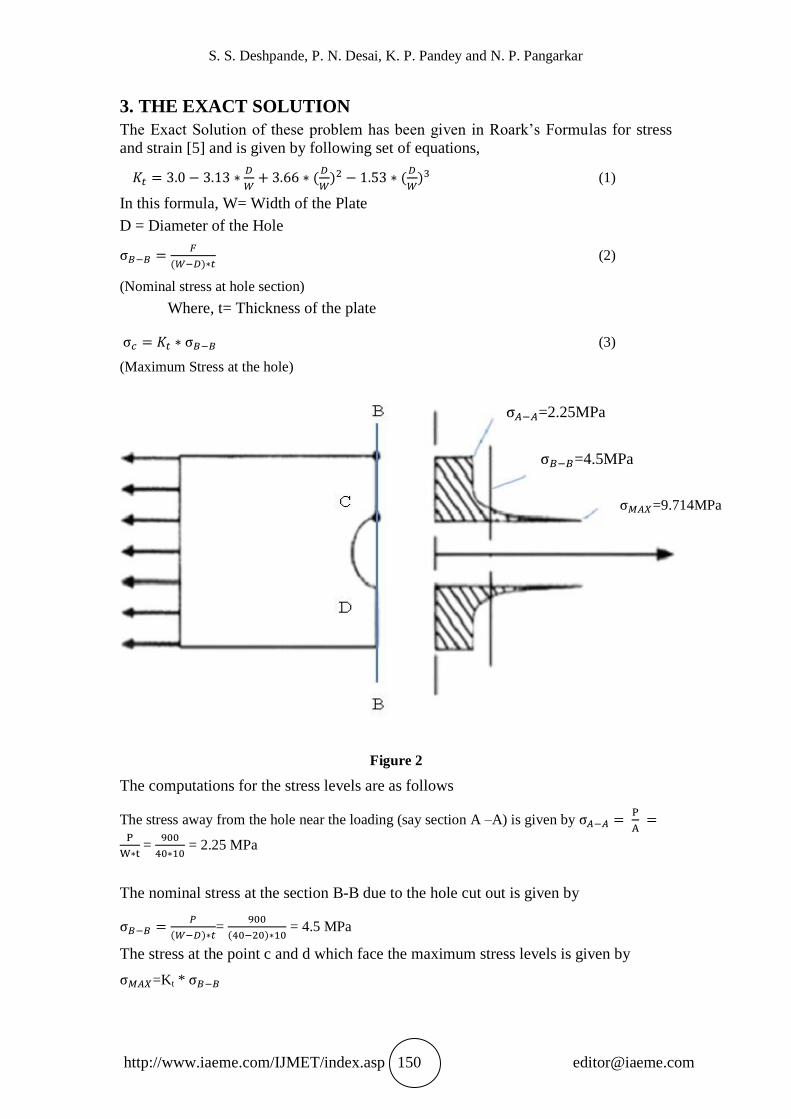
3. THE EXACT SOLUTION
The Exact Solution of these problem has been given in Roark’s Formulas for stress
and strain [5] and is given by following set of equations,
(1)
In this formula, W= Width of the Plate
D = Diameter of the Hole
(2)
(Nominal stress at hole section)
Where, t= Thickness of the plate
(3)
(Maximum Stress at the hole)
Figure 2
The computations for the stress levels are as follows
The stress away from the hole near the loading (say section A –A) is given by
=
= 2.25 MPa
The nominal stress at the section B-B due to the hole cut out is given by
=
= 4.5 MPa
The stress at the point c and d which face the maximum stress levels is given by
=Kt *
=2.25MPa
=4.5MPa
=9.714MPa

Detailed Studies on Stress Concentration by Classical and Finite Element Analysis
http://www.iaeme.com/IJMET/index.asp 151 [email protected]
We use the equation (1) to calculate Kt as follows:
= 2.158
Thus the exact value of the maximum stress at the hole at point C should be
9.714 MPa.
The representation of the stress levels in the plate at different sections and points
is shown in Fig 2.
4. FINITE ELEMENT ANALYSIS RESULTS
We have used several finite elements for analyzing the stress concentration. The
software used for finite element modeling i.e. preparation of the mesh is
HYPERMESH and we have used a combination of all available algorithms like ruled
/ mapped meshing , spline mesh, automesh for generating the elements in 2-
Dimensions . Three dimensional elements are also used in the analysis. The analysis
is done using the MSC NASTRAN solver. The results are post processed in
Hypermesh. We have taken only the von-Mises stress plots as they are the most
important. Further mesh refinement (approximately the number of elements is
doubled) has been carried out wherever it was felt that appropriate (i.e. say refined
mesh of linear quadrilateral vs. coarse mesh of second order quadrilateral) to study
whether the element gives a higher level of accuracy. The deflection of the hole is not
presented here as it would lead to very large number of plots but a comparison table
has been given so that the user can get an idea on the accuracy. The question on why
two meshes of coarse and fine are compared can be answered as in the industry ,
where stress concentration is not there , one often uses element sizes ranging from 10
mm to say 40 mm and in the region of stress concentration the size typically used
ranges from 3 to 6 mm . In the coarse mesh results presented here average size is
about 10 mm and fine mesh has an average size of 5 mm.
4.1 SHELL ELEMENTS
4.1.1 Quadrilateral element (First Order, 4 noded )
This is a shell element in NASTRAN it is identified as CQUAD4. One can see a
fantastic mesh quality Fig. 3 and the stress plots are given in Fig. No. 4
Figure 3 Coarse Quadrilateral (4 noded) mesh

S. S. Deshpande, P. N. Desai, K. P. Pandey and N. P. Pangarkar
http://www.iaeme.com/IJMET/index.asp 152 [email protected]
Figure 4-a Deformed shape plot
Figure 4-b Displacement plot
Figure 4-c Stress Diagram of coarse Quadrilateral mesh
Mesh refinement study was carried out and the results of which are presented in
Figures Fig. Nos. 5 and 6.

Detailed Studies on Stress Concentration by Classical and Finite Element Analysis
http://www.iaeme.com/IJMET/index.asp 153 [email protected]
Figure 5 Finemesh of 4 noded quadrilateral elements
Figure 6 Stress Diagram of 4 noded quadrilateral
4.1.2 Quadrilateral element (second order, 8 noded)
This is an eight noded shell element of the serendipity family as usually in FE
softwares we don’t have Lagrangian elements with which are fully second order
accurate with an internal node (i.e. 9 noded) The mesh remains the same as shown in
the Fig. No. 3 but only the element order has changed. Stress plots are shown in Fig. 7

S. S. Deshpande, P. N. Desai, K. P. Pandey and N. P. Pangarkar
http://www.iaeme.com/IJMET/index.asp 154 [email protected]
Figure 7 Coarse mesh of 2nd
order quadrilateral
Figure 8 Stress Diagram of 2nd
order coarse quadrilateral
Figure 9 Stress Diagram of 2nd
order quadrilateral fine mesh

Detailed Studies on Stress Concentration by Classical and Finite Element Analysis
http://www.iaeme.com/IJMET/index.asp 155 [email protected]
4.1.3 Traingular element (First order / 3 noded )
This is a three noded finite element and in NASTRAN terminology called as CTRIA3
) . It is not so commonly used as it has been found tp be much stiffer i.e predicts lesser
displacement and stress and hence the results can be misleading.
The corresponding mesh and the stress plot is shown in Fig. no. 8 and 9
Figure 10 Mesh of coarse 3 noded triangle
Figure 11 Stress Diagram of coarse 3 noded triangle
Various types of refined meshes are shown in the figures given below. These are
dependent on the various algorithms used for mesh splitting. We have found that in
one case it leads to a polyhedral type of mesh used very much in Computational fluid
dynamics nowadays. Although it is having lots of advantages with respect to
computational time by using a Finite Volume Method, we have to keep in mind that
such kind of meshes are not used in Structural mechanics. We also wish to keep in
mind that there are some studies going on in Structual mechanics on showing that
Finite Volume Method can be used for structural mechanics but this is limited only to
one dimensions and on the other hand Finite element methods have been widely used

S. S. Deshpande, P. N. Desai, K. P. Pandey and N. P. Pangarkar
http://www.iaeme.com/IJMET/index.asp 156 [email protected]
in the area of Computational Fluid dynamics. The mesh and the stress plots of these
refinements are shown in Fig Nos. 11 to 14.
Figure 12 Fine Mesh of coarse 3 noded triangle
Figure 13 Stress Diagram of finemesh 3 noded triangle
Figure 14 Another refinement of TRIA mesh Looking like a Polygon
Detailed Studies on Stress Concentration by Classical and Finite Element Analysis
http://www.iaeme.com/IJMET/index.asp 157 [email protected]
Figure 15 Stress plot of Another refinement of TRIA mesh Looking like a Polygon
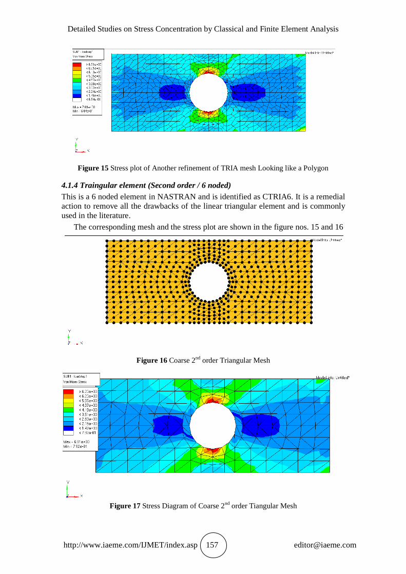
4.1.4 Traingular element (Second order / 6 noded)
This is a 6 noded element in NASTRAN and is identified as CTRIA6. It is a remedial
action to remove all the drawbacks of the linear triangular element and is commonly
used in the literature.
The corresponding mesh and the stress plot are shown in the figure nos. 15 and 16
Figure 16 Coarse 2nd
order Triangular Mesh
Figure 17 Stress Diagram of Coarse 2nd order Tiangular Mesh

S. S. Deshpande, P. N. Desai, K. P. Pandey and N. P. Pangarkar
http://www.iaeme.com/IJMET/index.asp 158 [email protected]
4.1.5 Ruled Quad mesh
In this type of mesh also called as mapped mesh, there is a one to one correspondence
between the nodes on the hole boundary and the nodes on the outer boundary. This
mesh looks good but apparently it has highly distorted quadrilaterals. This type of
mesh is typically used in Computational Fluid Dynamics simulations as there one
follows an Eulerian approach and the mesh doesn’t deform continuously as in the
Structural mechanics problems.
Figure 18 Ruled Qadrilateral Mesh (4 noded)
Figure 19 Stress plot of Ruled Quadrilateral mesh (4 noded )
4.1.6 Automesh results
This mesh algorithm works only when there is a surface and it is difficult to control
the mesh quality against that of the manual mesh created meshes. The user gets a feel
that he has used all quadrilaterals but the mesh gives some distorted elements as seen
in the mesh plot.

Detailed Studies on Stress Concentration by Classical and Finite Element Analysis
http://www.iaeme.com/IJMET/index.asp 159 [email protected]
Figure 20 Automesh of Quadrilaterals (4 noded )
Figure 21 Stress Plot of Automeshed Quadrilaterals
Figure 22 Fine Automesh of quadrilaterals

S. S. Deshpande, P. N. Desai, K. P. Pandey and N. P. Pangarkar
http://www.iaeme.com/IJMET/index.asp 160 [email protected]
Figure 23 Stress Plot on Fine Automeshed Quadrilaterals
4.1.7 Solid Elements
The Analysis was done using the same number of QUAD mesh extruded into
HEXAHEDRONS Coarse And Fine Mesh results are shown in the figures,23 and 25 .
The other elements considered were Tetrahedrons and Pentas .
Figure 24 Coarse Hexahedral mesh
Figure 25 Stress Diagram for coarse hexahedral mesh

Detailed Studies on Stress Concentration by Classical and Finite Element Analysis
http://www.iaeme.com/IJMET/index.asp 161 [email protected]
Figure 26 Fine Mesh of Hexahedrons
Figure 27 Stress Diagram for fine hexahedral mesh
The tetrahdraons are of two type. The four noded ones (TETRA4) are first order
accurate and the ten noded ones (TETRA10) are second order accurate. It is usual to
use second order tetrahedrons as the first order ones are quite stiff in practice. That is they give very less displacement as compared to the exact displacement. Most of the
automeshing in structural mechanics is done with second order tetras whereas for
fluids most of the meshing is done using first order accurate tetras as the equations
involve only first order derivatives.
The coarse and fine meshes for the first order tetrahedral elements are shown in
Fig. Nos. 27, 29 and Fig. 31 shows the coarse mesh for a second order accurate
tetrahedral element. The corresponding stress plots are given in Fig. Nos. 28, 30 and
Fig.No. 32.

S. S. Deshpande, P. N. Desai, K. P. Pandey and N. P. Pangarkar
http://www.iaeme.com/IJMET/index.asp 162 [email protected]
Figure 28 Coarse Mesh of 4 noded Tetrahedrons
Figure 29 Stress Plot of coarse 4 noded tetrahedral mesh
Figure 30 Fine Mesh of four noded Quadrilaterals

Detailed Studies on Stress Concentration by Classical and Finite Element Analysis
http://www.iaeme.com/IJMET/index.asp 163 [email protected]
Figure 31 Stress Plot of 4 noded tetrahedral fine mesh
Figure 32 Coarse Mesh of 10 noded tetrahedrons
Figure 33 Stress Plot of coarse 10 noded tetrahedral mesh
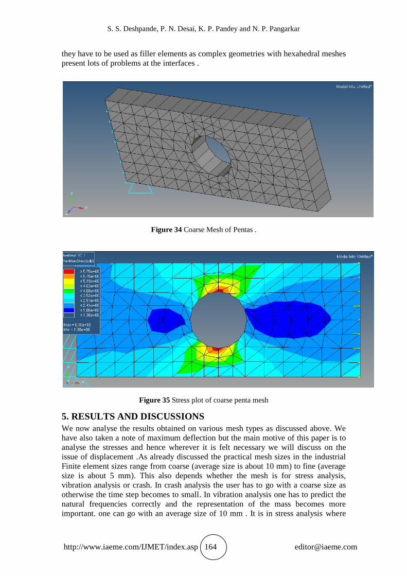
The Pentas are 6 noded elements commonly called as wedge or prism elements
and are not used commonly in structral mechanics as they are very stiff. However
S. S. Deshpande, P. N. Desai, K. P. Pandey and N. P. Pangarkar
http://www.iaeme.com/IJMET/index.asp 164 [email protected]
they have to be used as filler elements as complex geometries with hexahedral meshes
present lots of problems at the interfaces .
Figure 34 Coarse Mesh of Pentas .
Figure 35 Stress plot of coarse penta mesh
5. RESULTS AND DISCUSSIONS
We now analyse the results obtained on various mesh types as discussed above. We
have also taken a note of maximum deflection but the main motive of this paper is to
analyse the stresses and hence wherever it is felt necessary we will discuss on the
issue of displacement .As already discussed the practical mesh sizes in the industrial
Finite element sizes range from coarse (average size is about 10 mm) to fine (average
size is about 5 mm). This also depends whether the mesh is for stress analysis,
vibration analysis or crash. In crash analysis the user has to go with a coarse size as
otherwise the time step becomes to small. In vibration analysis one has to predict the
natural frequencies correctly and the representation of the mass becomes more
important. one can go with an average size of 10 mm . It is in stress analysis where

Detailed Studies on Stress Concentration by Classical and Finite Element Analysis
http://www.iaeme.com/IJMET/index.asp 165 [email protected]
the mesh has to be a mix of coarse (away from stress concentration region) and fine (
near the stress concentration ) and hence we have compared two types of meshes for
the elements. Deflection is not so important but it depends on the problem one is
solving. e,g. If the problem is to determine say the cylinder bore- distortion in an
Internal combustion engine in thermal analysis, then the major focus should be on the
displacement. In the present paper the main interest is stress which can also be used
further for fatigue analysis.
Sr.
No. Element
Mesh and the
type
Displacement
obtained by FEA
solution in mm
Von-Mises Stress obtained
by FEA solution in MPa
1 QUAD4 Coarse Mesh 0.149e-2 6.03
2 QUAD4 Fine Mesh 0.161e-2 7.50
3 QUAD4 Coarse Ruled
Mesh 0.1e-2 5.81
4 QUAD4 Fine Ruled
Mesh 0.11e-2 7.58
5 QUAD4 Coarse
Automesh 0.1e-2 5.10
6 QUAD4 Fine Automesh 0.11e-2 6.40
7 QUAD8 Coarse Mesh 0.165e-2 6.04
8 QUAD8 Fine Mesh 0.175e-2 7.47
9 TRIA3 Coarse Mesh 0.142e-2 7.29
10 TRIA3 Fine Mesh 0.142e-2 7.69
11
QUAD4
obtained
from TRIA3
Fine Mesh
polygonal type 0.157e-2 8.20
12 TRIA6 Coarse Mesh 0.159e-2 6.91
13 TRIA6 Fine Mesh 0.163e-2 8.03
14 HEXA8 Coarse Mesh 0.154e-2 5.90
15 HEXA8 Fine Mesh 0.152e-2 7.37
16 TETRA4 Coarse Mesh 0.148e-2 7.68
17 TETRA4 Fine Mesh 0.142e-2 9.11
18 TETRA10 Coarse Mesh 0.162e-2 7.65
19 PENTA6 Coarse Mesh 0.176e-2 6.98

S. S. Deshpande, P. N. Desai, K. P. Pandey and N. P. Pangarkar
http://www.iaeme.com/IJMET/index.asp 166 [email protected]
The major observations of the finite element analysis based on the table given above
are as follows:
1. The ruled mesh of quadrilaterals is unable to predict the stresses due to worst mesh
quality. The value of stress precdicted is much smaller than the exact value of 9.714
MPa. Such a kind of mesh should not be used for stress analysis. If a cfd result is
available from such a mesh then that result should be appropriately interpolated
before it can be used for structural analysis. Even though stress improves on a finer
mesh, displacement is not and hence this comment.
2. If one increases the order of the element from QUAD4 to QUAD8 then displacement
improves but the stress does not. This means that whether it is QUAD4 or QUAD8,
reasonable stress representation is obtained only on a fine mesh with a better
performance obtained by QUAD8 as compared to QUAD4.
3. The automesh results are also of the worst quality. Typically there is a blind practice
followed by the industry user to use an automesh and make it fine but as one can see
from the table, this belief is proven totally wrong. On a fine mesh, one doesn’t get the
required level of accuracy and still the stress is represented with a very less value.
4. The TRIA3 performs much better as compared to QUAD4. However the industry and
academics opinion about this element is that it is too stiff. This is true only for
bending. The present problem is of pure axial stress and a good performance of the
element is seen for such problems. The polygonal looking type of mesh performs
much better as compared to conventional refinement and this is not noted in the
literature of finite elements.
5. Increasing the order of the element from TRIA 3 to TRIA6 doesn’t necessarily
improve the stress. CTRIA 6 performs better on fine mesh with results comparable to
fine mesh of TRIA3.
6. HEXA8 performance improves on a fine mesh as compared to coarse mesh. Industry
belief is that hexahedral mesh is alsways better than the tetrahedral one is not
necessarily true. If one can use the automesh option using TETRA10 then results are
much accurate to the exact solution. Further for practical problems the time taken to
generate a hexahedal of tetesh is an order of magnitude greater than the tetrahedral
mesh. TETRA4 is better for stress analysis but displacement is predicted on the
conservative side and further cannot represent bending properly . So in our view a
fast algorithm for automesh with TETRA10 elements is much better as compared to
HEXA8.
7. The PENTA element does not represent the bending and is too stiff for frequency
calculations which is shown in the reference [13] and hence is not to be used for
practical finite element analyses where the same kind of mesh is to be used further for
vibration. For static stress analysis, results are much lesser than TETRA4 coarse and
TETRA10 coarse mesh. This justifies that this element is to be used only as a filler
element wherever necessary and should not be used in general.
6. CONCLUSION
We have presented a comparison of several meshes and element types in this paper
for analyzing a standard problem of stress concentration in a plate. One can see that
there is lot of variation of the results and if the user expects that he will get closer to
the exact value by using a fine mesh then it is not true. Using a fine mesh is also not
practical always. Thus the practical finite elementer has to keep in mind two things 1.
appropriate choice of element and 2. Desired mesh quality with lesser of distorted
elements. It is the authors’ observation sometimes that people simply fall in love with
their meshes and then don’t worry on the accuracy. This can be misleading. e.g. the
ruled mesh look fantastic but has severly distorted quadrilaterals and such types of
Detailed Studies on Stress Concentration by Classical and Finite Element Analysis
http://www.iaeme.com/IJMET/index.asp 167 [email protected]
meshes should not be used by the CAE community. One should not have any biases in
carrying out FEA as what may be appropriate for one type of analysis may not be for
another problem. We feel that if the user carries out such kind of studies apriori , then
he gets an idea of the accuracy. It is expected conclusions of this paper can help the
industrial finite element analysis and also throws a new light into the academic side of
the FEA research.
REFERENCES
[1] Bhandari, V. M, Design Of Machine Elements, Tata McGraw-Hill, 3rd Edition,
2012.
[2] Lingaiah, K. Machine Design Data Book, Tata McGraw-Hill, 2nd Edition, 2010,
Chapter 4.6 - 4.34.
[3] Pieterson, R. E., Design Factors for Stress Concentration, Machine Design,
Vol.23, No.27, Pentagon Publishing, 1951.
[4] Shigley, J. E. and Mitchell, L. D., Mechanical Engineering Design, McGraw-Hill,
NewYork, 1983.
[5] Orthwein, W., Machine Component Design, Jaico Publishing House, 3rd
Edition,
2004.
[6] Young, W. and Budynas, R, Roarks Formula’s for Stress and Strain, McGraw-
Hill , 8th Edition, 2011.
[7] Bhandari V. B, Macine Design Data Book, Tata McGraw-Hill 1st Edition, 2014.
[8] Reddy, B, Design Data Handbook, CBS Publishers3rd
Edition, 2012.
[9] PSG Design Data Hand Book, Coimbatore, 2012.
[10] Gokhale,N.S, Deshpande, S. S , Bedekar, S.V and Thite A.N , Practical Finite
Element Analysis, Finite to Infinite Publications, 2008
[11] Seshu, P, Textbook of Finite Element Analysis, Printise Hall Of India, 1st
Edition, 2014.
[12] Bhavikatti, S. S., Finite Element Analysis, New Age International Publishers, 3rd
Edition, 2015.
[13] Bandewar N.P and Deshpande,S.S, Comparison of several elements and their
performance in static and dynamic FEA , Paper presented at National Level
Conference on Advances in Mechanical Engineering Technology , MIT, Pune ,
March 2016 .