detail design subsystem design background and the dynamic part
DESCRIPTION
Detail Design Subsystem Design Background and the Dynamic Part. Objectives: Subsystem Design. Understand the purpose of Subsystem Design and where in the lifecycle it is performed - PowerPoint PPT PresentationTRANSCRIPT
1
Detail Design Subsystem Design Background and the
Dynamic Part

2
Objectives: Subsystem Design Understand the purpose of Subsystem Design and
where in the lifecycle it is performed Define the behaviors specified in the
subsystem's interfaces in terms of collaborations of contained classes (mentioned in Use Case Design)
Document internal structure of the subsystem Determine the dependencies upon elements
external to the subsystem that may be needed to support the responsibilities of the interface.

3
Subsystem Design in Context in the UP
Architect
Designer
ArchitecturalAnalysis
ArchitectureReviewer
Review theDesign
Review theArchitecture
Use-CaseAnalysis
ArchitecturalDesign
DescribeConcurrency
DescribeDistribution
ClassDesign
Subsystem Design
Use-Case Design
DesignReviewer
At this time in our Design, we have defined classes,subsystems, their interfaces,and their dependencies.
Have looked at components or sub-systems, i.e., ‘containers’ of complex behavior that we have treated as a black box.
Now we need to flesh out the internal interactions, i.e., what classes exist in the subsystem and how do they collaborate to supportresponsibilities documented in the subsystem interfaces.
This is what subsystem design is all about.

4
Subsystem Design in Context
Architect
Designer
ArchitecturalAnalysis
ArchitectureReviewer
Review theDesign
Review theArchitecture
Use-CaseAnalysis
ArchitecturalDesign
DescribeConcurrency
DescribeDistribution
ClassDesign
Subsystem Design
Use-Case Design
DesignReviewer
Here in subsystem design: We look at: 1) the detailed responsibilities of the subsystem and define and refine the classes needed to implement responsibilities, while
2) refining subsystem dependencies as needed.
The internal interactions areexpressed as collaborationsof classes and possibly othercomponents or subsystems.
The focus is on the subsystem.
The activity is iterative and recursive, but eventually feeds Class Design.

5
Subsystem Design Overview
SubsystemDesign
Use-Case Realization Use-Case Realization(updated)
Design Subsystems and Interfaces Design Subsystems and Interfaces(updated)
Design ClassesDesign
Guidelines
Subsystem Design is performed once per Design Subsystem.
Purpose: to define the behaviors specified in the interface via its contained classes: to document the internal structure of the subsystem, to define realizations between subsystem’s interface(s) and contained classes, & to determine the dependencies upon other subsystems.

6
Subsystem is a “cross between” a package and a class Has semantics of a package
(i.e., can contain other model elements) and a class (has behavior).
Subsystem realizes one or more interfaces which define its behaviors
<<subsystem>>Subsystem
NameInterface Subsystem
<<subsystem>>Subsystem Name
Interface
Realization (Canonical form)
Realization (Elided form)
<<interface>>Interface
Review: Subsystems and Interfaces

7
An interface is a model element which defines a set of behaviors (set of operations) offered by a classifier model element (e.g., class, subsystem or component).
A classifier may realize one or more interfaces. An interface may be realized by one or more classifiers.
<<subsystem>>Subsystem Name
Interface Subsystem
<<subsystem>>Subsystem Name
Interface
Realization (Canonical form)
Realization (Elided form)
<<interface>>Interface
Review: Subsystems and Interfaces

8
Interfaces are not classes; provide no default behavior. Realization is a semantic relationship between two classifiers
– one serves as contract (the interface ‘class’) ; other, carries it out that is ‘realizes’ the contract. via its subsystem contents and its dependencies
<<subsystem>>Subsystem Name
Interface Subsystem
<<subsystem>>Subsystem Name
Interface
Realization (Canonical form)
Realization (Elided form)
<<interface>>Interface
Review: Subsystems and Interfaces

9
Key is abstraction and encapsulation
A<<subsystem>>
B<<subsystem>>
C<<subsystem>>
Subsystem Guidelines Goals
Loose coupling; as independent as possible Insulation from change - minimized Replaceable elements in the model.
Strong Suggestions for Subsystems: Don’t expose details, only the interfaces
No element contained by a subsystem should have public visibility.
No element outside the subsystem should depend on a particular element inside the subsystem.
Only depend on interfaces of other model elements so that it is not directly dependent on any specific model element outside the subsystem.

10
Key is abstraction and encapsulation
A<<subsystem>>
B<<subsystem>>
C<<subsystem>>
Subsystem Guidelines
Exception: can share some class definitionsdone with packages in lower layers to ensurecommon definition of classes which must passbetween subsystems
All dependencies on a subsystem should be dependencies on the subsystem interfaces
only!!
clients not dependent on inside!
subsystem can be replaced by differentsubsystem that realizes same interface.

11
Modeling Convention for Subsystems and Interfaces
ICourseCatalogSystem
CourseCatalogSystem<<subsystem proxy>>
CourseCatalogSystem
<<subsystem>>
Represent subsystems as three items in model:1. <<subsystem>> package; 2. <<subsystem proxy>> class,3. subsystem interface (class with stereotype <<interface>>).
Subsystem package provides a container for the elements in the subsystem.
The interaction diagrams describe how thesubsystem elements collaborate to implement the operations of the interface the subsystem realizes,
Note: <<subsystem proxy>> class actually realizes the interface and will orchestrate the implementation of the subsystem operations.
Different (additional) interfaces would have their own proxy!

12
Subsystem Design: Major Steps Distribute Subsystem behaviors to Subsystem
Elements that is, the design components inside the subsystem.
Next, Document Subsystem Elements (e.g. classes…)
Document internal structural relationships among classes
Then document the interfaces upon which the subsystem itself is dependent.
Then, review the results of your subsystem design.
Now, let’s look at each of these

13
CourseCatalogSystem<<subsystem>>ICourseCatalogSystem
getCourseOfferings()
<<interface>>
subsystem responsibility
Subsystem Responsibilities Subsystem responsibilities defined by the interface it realizes When a subsystem realizes an interface, it makes a
commitment to support every operation defined by the interface. Interface operations may be realized by
Internal class operations (which may require collaboration with other classes or subsystems)
An interface realized by a contained subsystem.
16
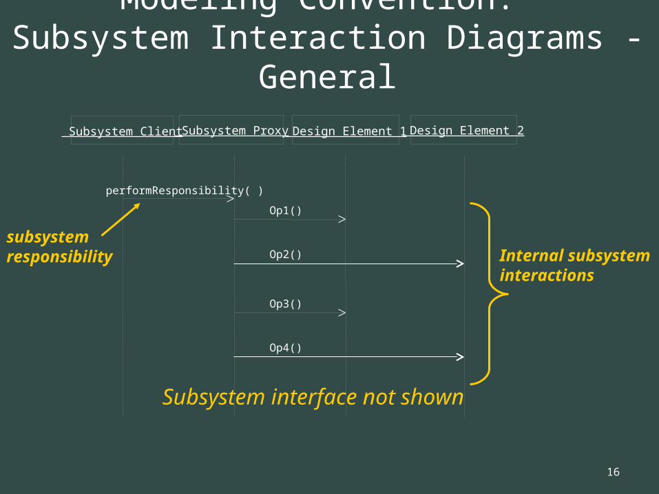
Modeling Convention: Subsystem Interaction Diagrams - General
Subsystem Client Subsystem Proxy Design Element 1
performResponsibility( )
Op1()
subsystem responsibility Op2()
Design Element 2
Op3()
Op4()
Internal subsystem interactions
Subsystem interface not shown

17
Modeling Convention: Subsystem Interaction Diagrams - General
Subsystem Client Subsystem Proxy Design Element 1
performResponsibility( )
Op1()
subsystem responsibilityOp2()
Design Element 2
Op3()
Op4()
Internal subsystem interactions
• A message should be drawn from the <<subsystem>> client to the <<subsystem proxy>>• Note: interface does not appear on internal subsystem interaction diagram.• Remainder of diagram should model how the <<subsystem proxy>> class delegates responsibility for performing the invoked operation to the other subsystem elements.
• Recommend you name the interaction diagram <interface name>::<operation name>>.• This convention simplifies future tracing of interface behaviors to the classes implementing the interface operations.

18
Example: CourseCatalogSystem Subsystem In Context (1 of 2)
subsystem interface
: Student
: RegisterForCoursesForm
: RegistrationController
: Schedule : Student : ICourseCatalogSystem
A list of the available course offerings for this semester are displayed
Student wishes to create a new schedule
1: // create schedule( )
4: // display course offerings( )
2: // get course offerings( )
3: getCourseOfferings(Semester)
subsystem responsibility
•This sequence diagram sets the context of what will be performed in Subsystem Design.
• Puts requirements on the subsystem, and
• Is the primary input specification to the task of creating local interactions within the subsystem.
Note: I have ‘cut’ a lot of detail out of this sequence diagram and the next one so that it is ‘easy’ to see the thrust of this slide…

19
Example: CourseCatalogSystem Subsystem In Context (2 of 2)
subsystem interface
: Student
: RegisterForCoursesForm
: RegistrationController
: Schedule : Student : ICourseCatalogSystem
1: // create schedule( )
2: // get course offerings( )
3: getCourseOfferings(Semester)
subsystem responsibility Legacy RDBMS
Database Access
• The ICourseCatalogSystem::getCourseOfferings() documentation specifies: “Retrieve the course offerings available for the specified semester.”
• So retrieval of the course offerings from legacy database is responsibility of CourseCatalog system. • Now, must show exactly HOW this is done using the RDBMS persistency mechanism. This will be shown when we actually do the subsystem design (ahead)

20
(Done:) Provide access to the class libraries needed to implement JDBC; (i.e., Provide java.sql package)
(Done. Seen in Persistency:) Create the necessary DBClasses and their dependencies (for objects requiring persistency) Remember, the proxy class is the class that manages the responsibilities
of the subsystem as found in its interface. You may think of it as a ‘control class’ for a particular interface.
Review slide 14 (and others) in lecture 29. DBClass and PersistentClassList and PersistentClass (and others) were stereotyped <<role>>, which implied their specific implementation is built by the designer when applying a mechanism such as persistency, legacy database access, etc. Recall DBClass had methods like read(), update(), delete() create()…
In the next couple of slides, we are doing exactly that with the DBCourseOffering class in attempting the access the legacy RDBMS to read data, execute a query, and more.
We have a DBCourseOffering along with CourseOfferingList and a CourseOffering to get results from executeQuery() (ahead)
Review: Incorporating JDBC: Steps of Steps
(continued)

21
more Note also that the Course Catalog System is clearly an
Actor, which, of course, it should be, AND it is shown as such – in place – in the Sequence Diagram.
Note that the proxy class, DBCourseOffering, and the objects within java.sql are all involved in constituting the interface with the legacy RDBMS system.
So, we are seeing HOW the Course Catalog Subsystem via the proxy class and its dependencies are handling responsibilities.
Note that the next couple of slides do NOT have the caveat ‘Context.’ They do not show the context for the subsystem or its interface;
rather, this is the design implementation of the interface! This is the subsystem design.

22
Ex: Local CourseCatalogSystem Subsystem Interaction
Subsystem Proxy
(represents Subsystem)
RDBMSRead
Retrieve all available course offerings for the current semester
CourseCatalogSystem Client
: CourseCatalogSystem
: DBCourseOffering
: CourseOffering
: CourseOfferingList
: ResultSet : Course Catalog : Statement : Connection
1. getCourseOfferings(Semester)
1.1. read(string)
1.1.1. createStatement( )
1.1.2. executeQuery(String)sql statement is passed in specifying the search criteria -- course offerings in the current semester
1.1.4. new( )
Repeat these operations for each element returned from the executeQuery() command.
The CourseOfferingList is loaded with the data retrieved from the database.
The getData and setData operations are called for each attribute in the each retrieved class instance.
3. setData( )
Create a list to hold all retrieved course offerings
Add the retrieved course offering to the list to be returned
2. getString( )
1.1.3. new( )
4. add(CourseOffering)
1.1.2.1. // executeQuery( )
• Internals of subsystems should yield interaction diagrams that look like this.• We see collaborations to implement the getCourseOfferings operation of the ICourseCatalogSystem interface.• Recall: legacy system stores course offerings in an RDBMS.• Here we show how the RDBMS persistency mechanism identified in Architectural Design is realized in the design.
CourseCatalogSystem (proxy) is in subsystem. DBCourseOffering object is created by designer (think DBClass in past lectures) as needed persistency and legacy interfacing. There is a dependency between the DBCourseOfferings and objects in java.sql starting with Connection and the actual access to the RDBMS via actor CourseCatalog. Note the design objects: CourseOfferingList and CourseOffering (no longer <<role>>

23
Ex: Local CourseCatalogSystem Subsystem Interaction
Subsystem Proxy
RDBMSRead
Retrieve all available course offerings for the current semester
CourseCatalogSystem Client
: CourseCatalogSystem
: DBCourseOffering
: CourseOffering
: CourseOfferingList
: ResultSet : Course Catalog
: Statement : Connection
1. getCourseOfferings(Semester)
1.1. read(string)
1.1.1. createStatement( )
1.1.2. executeQuery(String)sql statement is passed in specifying the search criteria -- course offerings in the current semester
1.1.4. new( )
Repeat these operations for each element returned from the executeQuery() command.
The CourseOfferingList is loaded with the data retrieved from the database.
The getData and setData operations are called for each attribute in the each retrieved class instance.
3. setData( )
Create a list to hold all retrieved course offerings
Add the retrieved course offering to the list to be returned
2. getString( )
1.1.3. new( )
4. add(CourseOffering)
1.1.2.1. // executeQuery( )
• To read the course offerings, the persistency client requests a service from the subsystem interface, represented by the proxy class, who asks the DBCourseOffering class to retrieve a course offerings for the specified semester.• DBCourseOffering creates a new statement using Connection class’s createStatement() operation.• The statement is executed; data is returned to ResultSet object. DBCourseOffering then creates a list of CourseOffering instances, CourseOfferingList, populates it with retrieved data, and returns it to the client.

24
If we have time, we’ll go through the Billing System. But the ideas are the same…
Idea behind the Billing System is almost the same, but the Billing System does not require a persistency mechanism.
Start with the Billing subsystem interface object in the next slide at the end…
Really showing how the submitBill(Student, double) is implemented in the subsystem. But first:
Billing System in Context – then Local

25
Example: Billing System Subsystem In Context
Send student and tuition to the Billing System, which will do the actual billing to the student for the schedule.
: Registrar : CloseRegistrationForm
: CourseOffering
: Schedule : Student. : IBillingSystem
: ICourseCatalogSystem
: CloseRegistrationController
Close registration for each course offering
Retrieve a list of course offerings for the current semester
If the maximum number of selected primary courses have not been committed, select alternate course offerings).
Currently assuming tuition based on number of offerings taken and certain attributes of students. If different offerings get different prices this will change slightly.
Repeat twice this is for simplicity; realistically, an indefinite number of iterations could occur)
Finally commit or cancel the course offering once all leveling has occurred
1. // close registration( )
2. // close registration( )
2.2. // close registration( )
1.1. // is registration open?( )
2.6. submitBill(Student, double)
2.3. // level( )
2.1. getCourseOfferings(Semester)
2.4. // close( )
2.5. getTuition( )
subsystem interface
subsystem responsibility
• Here, will demonstrate design of a subsystem that does not require a persistency mechanism. • This is at portion of the Close Registration use-case realization sequence diagram. The internals of the Billing System Subsystem
have not been designed yet. That is the purpose of this activity, Subsystem Design
Now, we are really after the next slide…

26
Example: Billing System Subsystem In Context
Send student and tuition to the Billing System, which will do the actual billing to the student for the schedule.
: Registrar : CloseRegistrationForm
: CourseOffering
: Schedule : Student. : IBillingSystem
: ICourseCatalogSystem
: CloseRegistrationController
Close registration for each course offering
Retrieve a list of course offerings for the current semester
If the maximum number of selected primary courses have not been committed, select alternate course offerings).
Currently assuming tuition based on number of offerings taken and certain attributes of students. If different offerings get different prices this will change slightly.
Repeat twice this is for simplicity; realistically, an indefinite number of iterations could occur)
Finally commit or cancel the course offering once all leveling has occurred
1. // close registration( )
2. // close registration( )
2.2. // close registration( )
1.1. // is registration open?( )
2.6. submitBill(Student, double)
2.3. // level( )
2.1. getCourseOfferings(Semester)
2.4. // close( )
2.5. getTuition( )
subsystem interface
subsystem responsibility
• Here we put requirements on the subsystem, and the sequence diagram is the primary input spec to creating local interactions for the subsystem.• We see the operations subsystem must support. Shows the simple way some client (CloseRegistrationController here) deals with the task of submitting bill to the legacy Billing System.
More coming…

27
•The IBillingsystem::submitBill() documentation specifies the following: “Billing information must be converted into a format understood by the external Billing System and then submitted to the external Billing System.
Thus the actual generation and submission of the bill is responsibility of the Billing System subsystem once the bill and proper parameters are passed to it.
But the billing information must be converted into a format that the Billing System can understand.
Let’s see how all this is done…
Explanation for next slides

28
Example: Local BillingSystem Subsystem Interaction
Billing System Client
: BillingSystem
: StudentBillingTransaction
: BillingSystemInterface
: Billing System : Student.
1. submitBill(Student, double)
1.1. create(Student, double)
1.2. submit(StudentBillingTransaction)
1.1.1. // get contact info( )
Retrieve the information that must be included on the bill
1.2.1. // open connection( )
1.2.2. // process transaction( )
1.2.3. // close connection( )
Subsystem Proxy
Logic here must convert the contract info into a format (StudentBillingTransaction) that the Billingsystem can understand.
Given this, the proxy will orchestrate opening, processing, and closing the connection (and submitting the bill).
No DBCourseOffering is needed hereBut StudentBillingTransaction is designed to convert data into a form the Billing System can understand from Student information and the ‘double.’ We simply see HOW the subsystem interface is realized.

29
Example: Local BillingSystem Subsystem Interaction
Billing System Client
: BillingSystem
: StudentBillingTransaction
: BillingSystemInterface
: Billing System : Student.
1. submitBill(Student, double)
1.1. create(Student, double)
1.2. submit(StudentBillingTransaction)
1.1.1. // get contact info( )
Retrieve the information that must be included on the bill
1.2.1. // open connection( )
1.2.2. // process transaction( )
1.2.3. // close connection( )
Subsystem Proxy
• The client object initiating the interaction is abstracted. Again, we don’t care…• The BillingSystem subsystem proxy class actually realizes the IBillingSystem interface and drives this realization by delegating the implementation of the interface to the subsystem elements.

30
Example: Local BillingSystem Subsystem Interaction
Billing System Client
: BillingSystem
: StudentBillingTransaction
: BillingSystemInterface
: Billing System : Student.
1. submitBill(Student, double)
1.1. create(Student, double)
1.2. submit(StudentBillingTransaction)
1.1.1. // get contact info( )
Retrieve the information that must be included on the bill
1.2.1. // open connection( )
1.2.2. // process transaction( )
1.2.3. // close connection( )
Subsystem Proxy
• The BillingSystem proxy class instance creates a StudentBillingTransaction specific to the external Billing System.• This transaction will be in a format that the Billing System can process.• The StudentBillingTransaction knows how to create itself using information from the given Student.
After creating the StudentBillingTransaction, the BillingSystem proxy class instance submits the transaction to the class instance that actually communicates with the Billing System.
Note that only a single message issent to the proxy: submitBill(…)The proxy, then, implements this responsibility by calling create(Student,double) and submit(StudentBillingTransaction).