designofawidebandesparantennafor v.g.tsiafakis,a.i
TRANSCRIPT

Progress In Electromagnetics Research B, Vol. 12, 183–199, 2009
DESIGN OF A WIDEBAND ESPAR ANTENNA FORDVB-T RECEPTION
V. G. Tsiafakis, A. I. Sotiriou, Y. I. PetropoulosE. S. Psarropoulos, E. D. Nanou, and C. N. Capsalis
Department of Electrical EngineeringDivision of Information Transmission Systemsand Material TechnologyNational Technical University of Athens9 Iroon Polytecneioy Str. 15772, Athens, Greece
Abstract—The design of an optimized Wideband ElectronicallySteerable Passive Array Radiator (W-ESPAR) antenna, for TerrestrialDigital Video Broadcasting (DVB-T) reception, is proposed. A geneticalgorithm is used in order to calculate the positions and lengthsof antenna elements (structural parameters) and loading conditions(control parameters). A nine-element W-ESPAR antenna with oneelement active and eight passive can have one directive beam perchannel, with mean gain of 9 dBi, reflection factor less than 0.2 andinput impedance around 75 Ohms. Computer simulations have shownthat one main lobe may be achieved in the same direction and for allUHF channels, from 470 MHz to 890 MHz. The analytical results forthe design are provided, and they show that the proposed W-ESPARantenna is suitable for portable DVB-T reception.
1. INTRODUCTION
The explosive growth of Terrestrial Digital Video Broadcasting (DVB-T) is opening an enormous market with heterogeneous technicalrequirements. All countries that belong to geographic area Region 1 [1]have built their network digital plans during May and June of 2006 inGeneva at the Regional Radiocommunication Conference (RRC-06) [2].Many of these countries have already begun their transition periodfrom analogue to digital terrestrial television and some others are readyto start in order to complete the process before the deadline, June of
Corresponding author: V. G. Tsiafakis ([email protected]).

184 Tsiafakis et al.
2015 [3]. Although the propagation conditions are the same for bothanalogue and digital transmission [4], the minimum E field required toachieve acceptable coverage is 3 to 20 dB higher for portable outdoorreception of a digital signal, depending on the system variant, whereasfor portable indoor reception a maximum of 8 dB must be added [5].
Network operators are searching for new solutions that willprovide broader bandwidth per user channel, better signal qualityand improved Quality of Service (QoS) so that customers will takethe advantages that DVB-T protocol offers. Even though manystudies have proven that smart antenna technology may provideconsiderable benefits such as capacity increase, coverage increase andC/I improvement, their mass deployment is still weak [6–8]. Highfabrication cost and complex configuration are the dominant factorsthat stall the installation of adaptive antenna systems. The costincreases with the number of radiator elements since the array needsthe same number of RF high power amplifiers or low noise amplifiers.The same applies to digital beamforming antennas (DBF) due to thefact that D/A and A/D converters are needed for each element [9].
The concept of W-ESPAR antenna is based on the electronicallysteerable passive antenna array radiator (ESPAR) which is a loadedport adaptive antenna array, developed during the last few years. Atypical ESPAR antenna is constructed from dipole elements withoutground plane or from monopole elements with a ground plane. Oneelement is active whereas the others are parasitic and have variableloads. The use of a circular ground plane of half wavelength radius witha skirt of a quarter wavelength that winds around it, can improve thehorizontal angle of the peak directivity [10]. The simple configuration,small size and low fabrication cost, makes it an attractive solutionfor adaptive beamforming. A nine element ESPAR antenna has9 dBi± 1 dB gain and null depth of −30 dBi± 10 dB for each directionand channel [11].
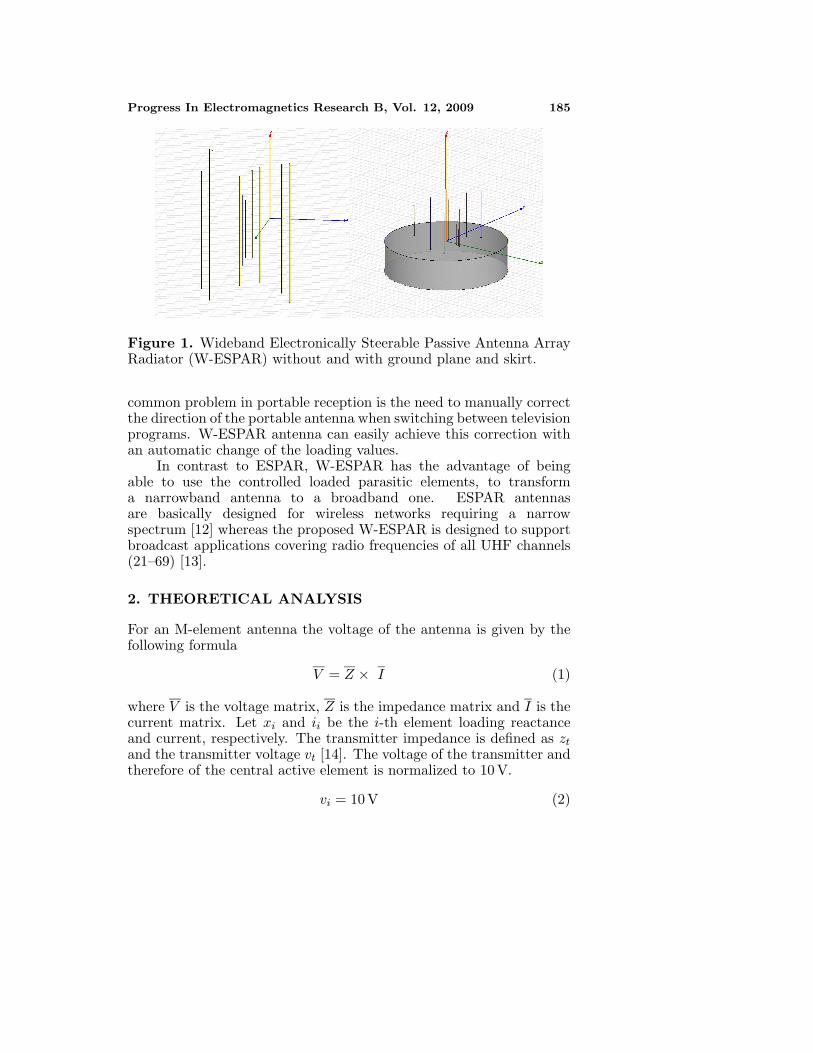
W-ESPAR has structural parameters identical to that of ESPAR.It consists of dipole elements without a ground plane, but can alsobe constructed with monopole elements with a ground plane (seeFig. 1). The parasitic elements are loaded with variable reactanceswhich regulate the current in order to change the characteristics of theantenna, such as antenna diagram, directivity, gain, reflection factorand input impedance, according to the designer’s needs.
The designed W-ESPAR antenna also exhibits beamformingcapabilities. With the appropriate loading values, it is possible tohave a slight steer of ±15 to the desirable reception direction. Thesecapabilities are very important, especially in portable reception, wheremultipath phenomena change the signal’s direction of arrival. A
Progress In Electromagnetics Research B, Vol. 12, 2009 185
Figure 1. Wideband Electronically Steerable Passive Antenna ArrayRadiator (W-ESPAR) without and with ground plane and skirt.
common problem in portable reception is the need to manually correctthe direction of the portable antenna when switching between televisionprograms. W-ESPAR antenna can easily achieve this correction withan automatic change of the loading values.
In contrast to ESPAR, W-ESPAR has the advantage of beingable to use the controlled loaded parasitic elements, to transforma narrowband antenna to a broadband one. ESPAR antennasare basically designed for wireless networks requiring a narrowspectrum [12] whereas the proposed W-ESPAR is designed to supportbroadcast applications covering radio frequencies of all UHF channels(21–69) [13].
2. THEORETICAL ANALYSIS
For an M-element antenna the voltage of the antenna is given by thefollowing formula
V = Z × I (1)
where V is the voltage matrix, Z is the impedance matrix and I is thecurrent matrix. Let xi and ii be the i-th element loading reactanceand current, respectively. The transmitter impedance is defined as zt
and the transmitter voltage vt [14]. The voltage of the transmitter andtherefore of the central active element is normalized to 10 V.
vi = 10 V (2)

186 Tsiafakis et al.
The parasitic elements are connected to imaginary loads and novoltage is applied to them. Therefore
Vpar(i) = −Ipar(i) × j × Xpar(i) (3)
where Vpar(i) is the voltage matrix, Ipar(i), the current matrix andXpar(i), the load matrix of the parasitic elements, 1 ≤ i ≤ M − 1.Using Equations (1), (2) and (3) the system voltage can be expressedin matrix form as:
V =
vt
00· · ·· · ·0
−
zt 0 0 · · · · · · 00 j ∗ x1 0 · · · · · · 00 0 j ∗ x2 · · · · · · 0· · · · · · · · · · · · · · · · · ·· · · · · · · · · · · · · · · · · ·0 0 0 · · · · · · j ∗ xM−1
i0i1i2· · ·· · ·
iM−1
(4)
Defining V1 as the voltage matrix and Zdiag as the impedancematrix, Equation (4) can be written as:
V = V1 − Zdiag ∗ I (5)
From (1) and (5):
V1 − Zdiag ∗ I = Z ∗ I ⇔ V1 = (Z + Zdiag) ∗ I (6)
and the current matrix I can now be easily calculated.Knowing the current flows, it is possible to evaluate the normalized
radiation pattern, the maximum gain and the input impedance. Theinput impedance is given according to the following formula:
Zin =vt
i0(7)
The reflection coefficient is given by
ρ =Zin − zt
Zin + zt(8)
where zt is equal to 75 Ω. The losses at the antenna input [15] arecalculated by
loss = −10 ∗ log10(1 − |ρ|2)(dB) (9)
where p is the absolute value of coef .

Progress In Electromagnetics Research B, Vol. 12, 2009 187
3. OPTIMIZATION STEPS
Optimization process was made in two phases. During the firstphase, the desirable values for the maximum gain, input impedanceand therefore reflection coefficient were set. A genetic algorithm(GA) [16, 17] was used in order to calculate the dimension, position andimaginary loads [18]. After several iterations the algorithm returnedthe characteristics of the antenna [19].
In our study, target gain, maximum accepted reflection coefficientand Z0 were set to 11 dB, 0.2 and 75 Ω, respectively. The optimizationprocess was carried out by taking into account multiple frequencies,spread in the whole UHF spectrum: 471.25 MHz, 551.25 MHz,631.25 MHz, 711.25 MHz, 791.25 MHz and 831.25 MHz. Mainly inRegion 1 [1], UHF spectrum is separated in 49 channels of 8 MHzeach (channel number 21–69). The selected frequencies were the visionfrequencies per channel according to the PAL B, G system [13] inanalog television.
The fitness function of the genetic algorithm, named error, is alinear combination of the normalized errors regarding the reflectioncoefficient and maximum gain. Defining:
error target(f) =∣∣∣∣p targer − p calculated
p target
∣∣∣∣2
(10)
error gain(f) =∣∣∣∣gain targer − gain calculated
gain target
∣∣∣∣2
(11)
where f is the frequency; p target is the value for the desirablereflection coefficient; p calculated is the calculated value; gain targetis the value for the desirable gain and gain calculated is the calculatedvalue [20].
Since multiple frequencies were taken into consideration, thefitness function was determined by the following formula
error =
12
f total∑f=f1
error target(f) +f total∑f=f1
error gain(f)
f total(12)
where f total is the number of frequencies selected for the simulation.The error function actually represents the mean value of two errors,gain and reflection coefficient. Using the mean value, both factors aretreated equally by the algorithm.
For the design of the antenna, 20 individuals formed eachgeneration of the GA. The initial ranges, from which the algorithm

188 Tsiafakis et al.
entry values were chosen, are presented in Table 1. The geneticalgorithm uses a uniform distribution for the selection of these values.Stochastic selection, scattered crossover with pcrossover = 0.8 anduniform mutation with rate equal to 0.2 were employed for the GA.Even though the imaginary loads were calculated during the firstoptimization stage, further optimization was considered necessary inorder to enhance the antenna characteristics.
Table 1. Initial range for algorithm parameters.
Element Length (x, y) Position Imaginary Load
Minimum value 0.05m (−0.3m, −0.3m) −250 j
Maximum value 0.35m (0.3m, 0.3m) 250 j
During the second phase, the antenna structural parameterswere kept the same as in the previous optimization phase. A newoptimization took place regarding exclusively the loading values.Therefore, the input origin of the GA is only the values of the variablereactances [21]. The process was carried out for all UHF channelsone by one. The second phase fitness function, error 2, followsEquation (12) where this time f total is equal to unity because onefrequency per optimization process is taken into consideration.
error 2 =error target(f) + error gain(f)
2(13)
The algorithm parameters, initial range of the loads (−250 j to250 j), stochastic selection, pcrossover = 0.8 and uniform mutation withrate equal to 0.2, were again employed.
4. SIMULATION PROCESS AND RESULTS
The design process was completed in four stages. During the first twostages, the simulation was performed according to the first phase ofoptimization, and took into account only one frequency at 631.25 MHz.In the first optimization phase, an eleven element antenna (one active,ten parasitic) was chosen. Further calculations during the secondoptimization phase, showed reflection coefficient values below 0.34for frequencies from 550 MHz up to 740 MHz. For the rest of thespectrum, the values were significantly higher. The second attemptwas made with a nine element antenna, having dipoles with double theradius compared to the dipoles of the previous case. The results werebetter regarding the lower spectrum frequencies, showing a reflection

Progress In Electromagnetics Research B, Vol. 12, 2009 189
coefficient value below 0.45 up to 710 MHz, but still not good enoughfor the upper frequencies.
In the third and final design stage, the simulation was performedaccording to the first optimization phase, taking into considerationmore than one frequency. Splitting uniformly the UHF spectrum,the following frequencies were chosen: 471.25 MHz, 551.25 MHz,631.25 MHz, 711.25 MHz, 791.25 MHz and 831.25 MHz. The thirdattempt was made with an eleven element antenna, and 2 mm radius foreach element. The error function of the genetic algorithm was slightlydifferent from Equation (12) and a weighting factor was assigned tothe spectrum central frequency, f = 631.25 MHz with respect to theother frequencies. Although the reflection coefficient values were below0.2, the gain presented significant fluctuations. The previous resultslead to the final simulations set, where a nine element antenna with2 mm element radius was chosen and the error function treated allthe frequencies equally. Fig. 2 and Fig. 3 show the final antennaconfiguration, whereas Table 2 summarizes the antenna structuralparameters.
Figure 2. Designed wideband ESPAR antenna in the x-y plane.
After having determined the physical antenna configuration, one

190 Tsiafakis et al.
Figure 3. Designed wideband ESPAR antenna in the x-y-z plane.
Table 2. Structural parameters of the antenna.
Element Element Radius (m) Element Length (m) (x, y) Position
#1 0.002 0.25261 0.29441, −0.09581
#2 0.002 0.26690 0.15156, −0.02453
#3 0.002 0.16159 0.27550, −0.08404
#4 0.002 0.26995 0.29922, −0.26796
#5 0.002 0.29781 0.21579, 0.08535
#6 0.002 0.20220 −0.07384, −0.09320
#7 0.002 0.34936 0.17811, −0.25096
#8 0.002 0.13269 0.25410, −0.07396
#9 0.002 0.32100 0.29808, 0.13437
simulation for each UHF channel has been implemented in order tocalculate the loading values. Fig. 4 to Fig. 6 show the maximumantenna gain, the reflection coefficient and input impedance for eachDVB-T channel and Table 3 and Table 4 summarize the parasiticelements loading values.
Figure 4 demonstrates the antenna gain for the whole UHFband which is relatively stable, without any deep fluctuations. Themaximum value is 9.8259 dBi at 575.25 MHz and the minimum is equal

Progress In Electromagnetics Research B, Vol. 12, 2009 191
Figure 4. Gain of designed W-ESPAR antenna for frequencies from471.25 MHz up to 831.25 MHz.
Figure 5. Reflection coefficient for frequencies from 471.25 MHz upto 831.25 MHz.
Figure 6. Zin of designed W-ESPAR antenna for frequencies from471.25 MHz up to 831.25 MHz.

192 Tsiafakis et al.
to 7.8679 dBi at 655.25 MHz. Therefore, the maximum deviation is lessthan 2 dB and the antenna has an average gain of 9 dBi approximately.Fig. 5 presents the reflection coefficient variation. The maximum valueappears at 663.25 MHz and is equal to 0.1721, a value that is 13.9%smaller than the target value of 0.2. The minimum reflection coefficientis 0.0056 at the 471.25 MHz. Next, Fig. 6 presents the antenna inputimpedance. Fig. 7 to Fig. 12 present the azimuth and elevationdiagrams of the designed antenna for several radio frequencies.
Figure 7. Radiation patterns for frequencies: 471.25 MHz,487.25 MHz, 503.25 MHz and 519.25 MHz (azimuth plane & elevationplane).
Figure 8. Radiation patterns for frequencies: 535.25 MHz,551.25 MHz, 567.25 MHz and 583.25 MHz (azimuth plane & elevationplane).
Having determined the physical antenna configuration and theloading values for each UHF channel, one last simulation has beenimplemented in order to achieve beamforming capabilities [22]. Withspecific loading values, it is possible to achieve a slight steer of thedesirable reception angle. Simulation results have shown that instead

Progress In Electromagnetics Research B, Vol. 12, 2009 193
Table 3. (a) Imaginary loads of parasitic elements.
Frequency
(MHz)Va1 Va2 Va3 Va4 Va5 Va6 Va7 Va8
471.25 55 j 290 j 174 j −2 j 212 j −122 j 39 j 152 j
479.25 35 j 280 j 299 j −2 j 207 j −130 j 137 j −125 j
487.25 14 j 277 j 288 j −12 j 209 j −130 j 141 j −101 j
495.25 14 j 245 j 290 j −32 j 185 j −169 j 261 j −238 j
503.25 −6 j 267 j 294 j −43 j 205 j −149 j 154 j −100 j
511.25 −18 j 285 j 284 j −55 j 191 j −166 j −296 j −112 j
519.25 −40 j 266 j 299 j −62 j 177 j −188 j 121 j −150 j
527.25 −51 j 275 j 299 j −76 j 168 j −105 j 76 j −161 j
535.25 −60 j 271 j 255 j −89 j 151 j −226 j 120 j −191 j
543.25 −96 j −291 j 286 j −99 j 154 j −248 j −297 j −202 j
551.25 −91 j −146 j 295 j −120 j 138 j −256 j −63 j −205 j
559.25 −108 j 76 j 290 j −131 j 124 j −288 j −178 j −240 j
567.25 −140 j 85 j 294 j −149 j 131 j −294 j 234 j −230 j
575.25 −157 j 130 j 290 j −157 j 117 j −296 j 279 j −266 j
583.25 −178 j 144 j 206 j −177 j 105 j −297 j 250 j −290 j
591.25 −213 j 136 j 296 j −191 j 105 j −298 j 252 j −290 j
599.25 −237 j 131 j 296 j −213 j 94 j −299 j 254 j −298 j
607.25 −251 j 143 j 161 j −249 j 86 j −295 j 185 j −299 j
615.25 −194 j 146 j 188 j −263 j 59 j −298 j 180 j 299 j
623.25 −223 j 139 j 153 j −282 j 52 j −299 j 193 j 291 j
631.25 −231 j 136 j 188 j −299 j 40 j −299 j 181 j 294 j
639.25 −222 j 134 j 299 j −296 j 25 j −295 j 147 j 297 j
647.25 −110 j −299 j 211 j −45 j 159 j −299 j 207 j −23 j
655.25 −32 j 106 j 137 j −147 j 72 j −299 j 131 j −78 j
663.25 −75 j 105 j 178 j −65 j 76 j −299 j 259 j −35 j
671.25 −172 j 120 j 166 j 295 j −69 j −298 j 194 j −84 j
679.25 −127 j 99 j 121 j −69 j 56 j −294 j 196 j −82 j
687.25 −203 j 96 j 151 j 298 j −16 j −299 j 178 j 112 j
695.25 −175 j 91 j 121 j −25 j 39 j −297 j 182 j −107 j
703.25 −191 j 86 j 77 j −11 j 28 j −277 j 188 j −101 j
of having maximum gain at 0 degree, the main lobe may be directed toan angle of ±15. The gain as well as input impedance and reflectionfactor remain in the same range. Fig. 13 and Fig. 14 present the resultsof azimuth and elevation diagrams, showing a maximum reception gain

194 Tsiafakis et al.
Table 4. (b) Imaginary loads of parasitic elements.
Frequency
(MHz)Va1 Va2 Va3 Va4 Va5 Va6 Va7 Va8
711.25 −249 j 83 j 89 j 297 j −87 j −295 j 169 j −137 j
719.25 −215 j 77 j 66 j 50 j 1 j −292 j 171 j −73 j
727.25 −233 j 71 j 52 j 62 j −5 j −299 j 172 j −105 j
735.25 −268 j 71 j 109 j 68 j −13 j −286 j 162 j −132 j
743.25 −272 j 59 j 48 j 104 j −7 j −291 j 186 j −104 j
751.25 −285 j 60 j 61 j 169 j −41 j −299 j 155 j −156 j
759.25 −291 j 55 j 50 j 212 j −59 j −298 j 152 j −173 j
767.25 −299 j 52 j 42 j 173 j −64 j −292 j 147 j −135 j
775.25 −297 j 42 j 11 j 135 j −81 j −289 j 158 j −143 j
783.25 −299 j 42 j −29 j 58 j −130 j −287 j 148 j −298 j
791.25 −296 j 35 j −7 j 78 j −110 j −299 j 147 j −9 j
799.25 −299 j 29 j −37 j 25 j −133 j −299 j 147 j −40 j
807.25 −281 j 31 j −39 j 4 j −143 j −281 j 132 j 56 j
815.25 −299 j 30 j −29 j 167 j −160 j −299 j 123 j 21 j
823.25 −300 j 22 j −55 j −1 j −188 j −299 j 126 j 79 j
831.25 −300 j 20 j −65 j 21 j −212 j −299 j 120 j 127 j
Figure 9. Radiation patterns for frequencies: 599.25 MHz,615.25 MHz, 631.25 MHz and 647.25 MHz (azimuth plane & elevationplane).
at +15 and −15 respectively, for frequency equal to 531.25 MHz.Table 5 summarizes the antenna characteristics for the above two cases.In order to verify the results concerning the maximum gain of theantenna, a simulation using the software package HFSS was made.

Progress In Electromagnetics Research B, Vol. 12, 2009 195
Figure 10. Radiation patterns for frequencies: 663.25 MHz,679.25 MHz, 695.25 MHz and 711.25 MHz (azimuth plane & elevationplane).
Figure 11. Radiation patterns for frequencies: 727.25 MHz,743.25 MHz, 759.25 MHz and 775.25 MHz (azimuth plane & elevationplane).
Figure 12. Radiation patterns for frequencies: 791.25 MHz,807.25 MHz, 823.25 MHz and 831.25 MHz (azimuth plane & elevationplane).

196 Tsiafakis et al.
Figure 13. Radiation pattern with maximum reception gain at +15for 531.25 MHz (azimuth plane & elevation plane).
Table 5. Parameters of the antenna for different maximum directiongain.
Direction of Maximum Antenna Gain +15
Maximum Antenna Gain Value 9.6 dBi
Reflection Coefficient 0.096
Imaginary Loads
VA1 VA2 VA3 VA4 VA5 VA6 VA7 VA8
−66 j −22 j 64 j −126 j 137 j −200 j 84 j −179
Direction of Maximum Antenna Gain −15
Maximum Antenna Gain Value 8.4 dBi
Reflection Coefficient 0.1078
Imaginary Loads
VA1 VA2 VA3 VA4 VA5 VA6 VA7 VA8
−11 j 171 j 197 j −132 j 112 j −199 j 198 j −156
Figure 14. Radiation pattern with maximum reception gain at −15for 531.25 MHz (azimuth plane & elevation plane).

Progress In Electromagnetics Research B, Vol. 12, 2009 197
The calculations were made for the frequencies 471.25, 655.25, 743.25and 799.25 MHz and the corresponding values of the maximum gainare 8.61, 8.6, 8.36 and 6.35. The comparison between these values andthe values of our analysis showed a small variation which verifies theconsistency of the results of our study.
5. CONCLUSIONS
The proposed W-ESPAR antenna is a wideband antenna with onesteerable directive beam, mean gain of 9 dBi and reflection factorless than 0.2, using parasitic elements that are loaded with variablereactances.
In this paper, a genetic algorithm was used in two phases. In thefirst phase the structural characteristics of the antenna were defined.Due to time and computing limitations, only six vision frequencies,corresponding to the channels 21, 31, 41, 51, 61 and 66 in the UHFband, were used. In the second phase the values of the variable loadswere calculated. The calculations were made for each UHF channel.
The algorithm was set to achieve not only good characteristicsof the antenna in all UHF channels, but also steerable capabilities.An electronic steer range of 30(−15,+15) was accomplished withspecific values for the variable loads on each occasion. For alloptimization phases, 20 individuals formed each generation of the GA.With a larger population, the algorithm would search a wider solutionspace but with much slower rate.
In ESPAR antenna, adaptive radiation characteristics areprovided by controlling the current in the variable reactances. Onthe contrary, W-ESPAR antenna uses the variable reactances in orderto achieve stable antenna gain and reflection factor in whole UHF band(approximate bandwidth of 400 MHz) and a slight steer of the directivebeam. The dimensions of W-ESPAR antenna (40 × 50 × 34 cm) makeit suitable for domestic use, for fixed and portable indoor reception ofanalogue and digital terrestrial television. The antenna design in thecurrent study considers dipole elements without ground plane. LikeESPAR antennas, the proposed W-ESPAR may be implemented withmonopole elements and a ground plane. This is going to reduce theheight of the antenna structure and make it more stable.
W-ESPAR is not probably the appropriate name for this antenna,mainly because it is not fully steerable, even though the completedesign of the structure, the use of the variable reactances and thesteer of the directive beam for at least 30 explain the selection of thename. This approach of antenna designing provides portable solutionsfor fixed, portable indoor and outdoor reception for both analogue and

198 Tsiafakis et al.
digital television.In terrestrial television, broadcasters use more than one
transmitter in order to cover big cities or areas where the requiredfield strength is not achieved. Normally, users have the experience toorient the antenna and achieve better image quality. The proposed W-ESPAR antenna gives users the capability to accomplish better signalquality and an automatic orientation of the antenna when switchingbetween television channels.
REFERENCES
1. International Telecommunication Union, Radio Regulations,Edition of 2007.
2. International Telecommunication Union, Final Acts of theRegional Radiocommunication Conference for Planning of theDigital Terrestrial Broadcasting Service in Parts of Regions 1 and3 in the Frequency Bands 174–230MHz and 470–862MHz (RRC-06), Geneva, 2006.
3. International Telecommunication Union, Final Acts of theRegional Radiocommunication Conference for the Revision of theStockholm 1961 Agreement (RRC-06-Rev.ST61), Geneva, 2006.
4. European Conference of Postal and Telecommunications Admin-istrations, The Chester 1997 Multilateral Coordination AgreementRelating to Technical Criteria, Coordination Principles and Pro-cedures for the Introduction of Terrestrial Digital Video Broad-casting (DVB-T), Chester, July 25, 1997.
5. International Telecommunication Union, DTTB Handbook DigitalTerrestrial Television Broadcasting in the VHF/UHF Bands,Radiocommunication Bureau Edition, 2002.
6. Lozano, A., F. R. Farrokhi, and R. A. Valenzuela, “Lifting thelimits on high-speed wireless data access using antenna arrays,”Communications Magazine, Vol. 39, No. 9, 156–162, September2001.
7. Herscovici, N. and C. Chrostodoulou, “Why have smart antennasnot yet gained any traction with wireless network operators,”IEEE Antennas and Propagation Magazine, Vol. 47, No. 6,December 2005.
8. Lehne, P. H. and M. Pettersen, “An overview of smartantenna technology for mobile communication systems,” IEEECommunications Surveys, Vol. 2, No. 4, 2–13, Fourth Quarter,1999.
9. Liberti, J. C. and T. S. Rappaport, Smart Antennas for

Progress In Electromagnetics Research B, Vol. 12, 2009 199
Wireless Communication: IS-95 and Third Generation CDMAApplications, Prentice Hall, 1999.
10. Gyoda, K. and T. Ohira, “Electronically steerable passive arrayradiator antennas for low-cost analog adaptive beamforming,”Proc. 2000 IEEE International Conference on Phased ArraySystems and Technology, 101–104, 2000.
11. Kawakami, H. and T. Ohira, “Electronically Steerable PassiveArray Radiator (ESPAR) antennas,” IEEE Antennas andPropagation Magazine, Vol. 47, No. 2, April 2005.
12. Gyoda, K. and T. Ohira, “Design of Electronically SteerablePassive Array Radiator (ESPAR) antennas,” 2000 IEEE Antennasand Propagation Society International Symposium, 922–925, 2000.
13. International Telecommunication Union, Final Acts of theEuropean Broadcasting Conference in the VHF and UHF Bands,Stockholm, 1961.
14. Capsalis, C. and P. Kottis, Keraies Asyrmates Zefkseis, TziolasEditions, Athens, Greece, 2007.
15. Balanis, C. A., Antenna Theory Analysis and Design, John Wiley& Sons, 2005.
16. Goldberg, D. E., Genetic Algorithms in Search, Optimization, andMachine Learning, Addison-Wesley, 1989.
17. Rahmat-Samii, Y. and E. Michielssen, Electromagnetic Optimiza-tion by Genetic Algorithms, John Wiley & Sons Inc., 1999.
18. Sijher, T. S. and A. A. Kishk, “Antenna modeling by infinitesimaldipoles using genmetic algorithms,” Progress In ElectromagneticsResearch, PIER 52, 225–254, 2005.
19. Meng, Z.-Q., “Autonomous genetic algorithm for functionaloptimization,” Progress In Electromagnetics Research, PIER 72,253–268, 2007.
20. Orchard, B., Optimizing Algorithms for Antenna Design, M.Sc.Dissertation, University of the Witwatersrand, 2002.
21. Mitilineos, S. A., C. A. Papagianni, G. I. Verikaki, andC. N. Capsalis, “Design of switched beam planar array usingthe method of genetic algorithms,” Progress In ElectromagneticsResearch, PIER 46, 105–126, 2004.
22. Lee, K.-C., “A genetic algorithm based direction finding techniquewith compensation of mutual coupling effects,” Journal ofElectromagnetic Waves and Applications, Vol. 17, No. 11, 1613–1624, 2003.