designing a water supply system for livestock
TRANSCRIPT

1
Designing a water supply system for livestock

2
Contents 3 Introduction
4 Water supply
- Water supply regulations
- Preventing contamination of incoming mains water supplies
- Source of supply
- Treatment of incoming supply
6 On-site storage
7 Pumping and distribution
- Pumping systems
- Pipe diameter and water velocity
- Treatment via water
- Demand
9 Design of a water distribution system
- Step-by-step system design
- Determining the pipe diameter for laterals
- Flow calculations for water
20 Auditing and improvements to existing systems
21 Frequently asked questions
22 References
23 Appendices
The information in this booklet has been sourced from Reading Agricultural Consultants. AHDB Pork is grateful to all those who have commented on and contributed to this publication.

3
This guide covers a wide range of issues that should be taken into consideration when designing a water supply system for a pig unit. These include infrastructure, cleaning and in-water medication, as well as the design of distribution and drinking systems. The guide includes standard values and calculations, which are a basis for ensuring that water is distributed safely, at flow rates and pressures that deliver volumes to satisfy the demand from livestock.We aim to provide readers with an understanding of what is involved in the design of a water supply system and assist with decision making, either to improve existing systems or, when installing a new one.This guide will support readers when discussing plans with installers as well as helping them avoid common pitfalls. It also includes important points to be aware of and take into consideration, including regulatory compliance.
Introduction
Nigel PenlingtonAHDB Head of Environment and Buildings

4
Water Supply
The Water Supply (Water Fittings) Regulations 1999 Farm premises, like all others served by a public water supply, must comply with The Water Supply (Water Fittings) Regulations 1999 (The Stationery Office Limited, 1999).By following the requirements of these regulations, farmers protect the water supply from contamination, both on the farm and upstream. The Regulations are designed to prevent the waste of water (avoiding a waste of money where supplies are metered) and to ensure farmers have reliable and robust plumbing systems. Most importantly, they are to protect supplies of potable (human drinking quality) water from contamination by substances present, or used, on the farm such as faecal matter, chemicals or pharmaceutical products.Compliance with the Water Supply Regulations is enforced by water supply companies, which subscribe to the Water Regulations Advisory Scheme (WRAS). This body approves plumbing, pipes and fittings for use in connection to the public water supply. The term WRAS has become shorthand in the UK, covering three separate areas.The first is WRAS itself, which is a subscription membership company; subscribers are the 26 UK water suppliers (WRAS, 2018). The second is where WRAS is used as shorthand for ‘meeting the Water Regulations of 1999,’ which is not, in fact, the case. The third use is for approved plumbing fittings.It is not illegal to install a product, such as water fittings, in the UK without the WRAS mark, but you may have to prove compliance in other ways.Preventing contamination of incoming mains water supplies Water supplies to livestock accommodation and yard areas must be protected by an air gap to prevent the backflow of potentially contaminated or medicated water into the public supply. All pipes and fittings before the air gap must meet the standards set by the regulations. It is recommended that any pipes and fittings after the air gap are approved by WRAS; it is in the farm’s business interest that fittings do not leak or contaminate the supply. Domestic or staff facilities must be zoned or separate to any systems serving livestock.
RememberLivestock farm water supplies are rated as Category 5 installations, the highest risk fluid category, as faecal material and chemicals represent a serious health hazard.
SgVAir gap
Air gap
Outlet
SL
TYPE AA air gap withunrestricted dischargeabove spill-over level.
Suitable for protection againstfluid category:
5 Backpressure
Backsiphonage5
TYPE AB air gap withweir overflow.
Suitable for protection againstfluid category:
5 Backpressure
Backsiphonage5
SgVWeir
overflow
Figure 1. Header tank air gap arrangements for Category 5 installations
Source: Water Regulations Advisory Scheme (Water Regulations Advisory Scheme, 2012, p. 4)
The vertical distance of the discharge point of the inlet pipe above the spill-over level must be at least twice the bore of the inlet pipe and never less than 20mm.
Figure 1 shows how an air gap should be created in header tanks to protect the public water supply from contamination with medicines, faecal material and pathogens. To meet these regulations, trough and bowl drinkers have the float valve sitting in a header box above the top of the sides.Where both mains and private supply are present, a dual supply arrangement of inlet valves is required. The inlet valve for the mains water supply must be above any others, to give the greatest level of protection.
It is a legal requirement (Regulation 5) to notify your water provider of any new installation work, or where an existing non-house (domestic) system is being extended or altered in any way.

5
Source of supply If connected to the public water supply from the water company-owned distribution mains, it is reasonable to assume that the supply at the meter is safe to drink (potable) and free from contamination. However, treatment may include chlorination and sometimes fluoridation, which may have an impact on herd health.Private water supplies, for example from boreholes, springs or surface water, are less reliable in terms of microbial and chemical content. These supplies may require treatment to bring the water up to a standard that is suitable for pigs to drink. Treatment may include ultraviolet light (UV) for microbial contamination and chemical dosing or filtration to remove iron, suspended solids and other contaminants.On-farm supplies should be protected from contamination by implementing the precautions set out in the Code of Good Agricultural Practice (COGAP) for farmers, growers and land managers (Defra, 2009). Manures and slurries should not be stored on, or applied to, land within 50m of a borehole used for private water supplies. Such boreholes should not be located within 50m of a soakaway attached to a domestic septic tank system, a sprayer wash-down pad, a blind ditch soakaway or a biobed. In some limestone and sandstone aquifers, greater protection may be necessary to protect supplies against microbial contamination.
Treatment of incoming supplyWhere water quality is poor or the supply is at risk of contamination, tests should be carried out to determine the nature and degree of treatment necessary to bring the supply up to potable standard or, if for livestock use only, suitable for that purpose. Basic testing of private supplies should be undertaken regularly, with samples taken from the primary outlet from the source to storage, or, in the case of pressurised borehole-fed systems, from an outlet at the head of the borehole. Testing should be carried out for the following parameters, which are directly related to a healthy supply: lead, copper, nickel, Escherichia coli (E. coli) and Enterococci. The following parameters should also be tested to indicate general water quality and to assess potential impacts of the water on the distribution system: smell, taste, biological oxygen demand, hardness, suspended solids, conductivity (salinity) and iron.Treatment systems should be capable of handling the full rate of flow of the farm supply and the water placed in suitable storage to provide a buffer against breakdown and other breaks in supply.
6
Table 1. Daily water requirements and minimum flow rates
Pig categoryMinimum daily
requirement (l/head)
Minimum flow through nipple drinker (l/min)
Newly weaned 1.0–1.5 0.3
Up to 20kg 1.5–2.0 0.5–1.0
20–40kg 2.0–5.0 1.0–1.5
Finishing pigs up to 100kg 5.0–6.0 1.0–1.5
Sows and gilts pre-service and in-pig
5.0–8.0 2.0
Sows and gilts in lactation 15–30 2.0
Boars 5.0–8.0 2.0
Source: Paragraph 72 of the Defra Code of Recommendations for the Welfare of Livestock: Pigs (Defra, 2003)
It is important to consider the risks to pig welfare should there be any disruption to water supply, and the availability of alternative supplies.
On-site storage
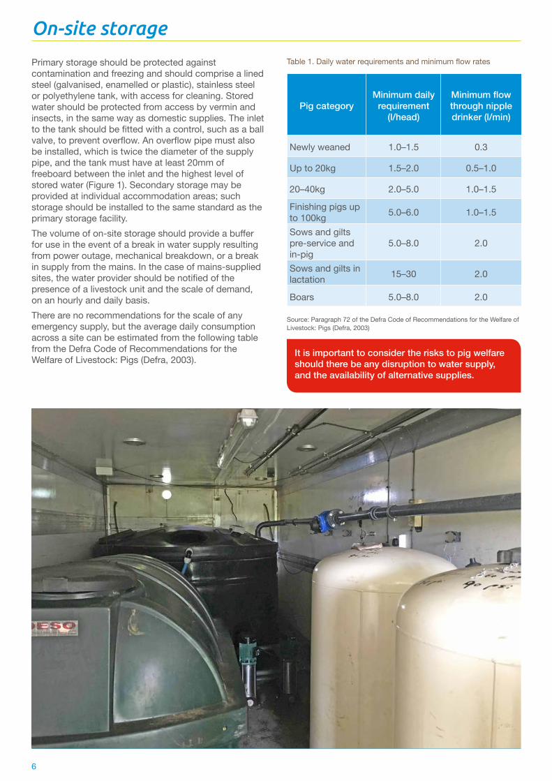
Primary storage should be protected against contamination and freezing and should comprise a lined steel (galvanised, enamelled or plastic), stainless steel or polyethylene tank, with access for cleaning. Stored water should be protected from access by vermin and insects, in the same way as domestic supplies. The inlet to the tank should be fitted with a control, such as a ball valve, to prevent overflow. An overflow pipe must also be installed, which is twice the diameter of the supply pipe, and the tank must have at least 20mm of freeboard between the inlet and the highest level of stored water (Figure 1). Secondary storage may be provided at individual accommodation areas; such storage should be installed to the same standard as the primary storage facility.The volume of on-site storage should provide a buffer for use in the event of a break in water supply resulting from power outage, mechanical breakdown, or a break in supply from the mains. In the case of mains-supplied sites, the water provider should be notified of the presence of a livestock unit and the scale of demand, on an hourly and daily basis.There are no recommendations for the scale of any emergency supply, but the average daily consumption across a site can be estimated from the following table from the Defra Code of Recommendations for the Welfare of Livestock: Pigs (Defra, 2003).

7
Pumping and distribution
Pumping systemsPumping systems can be categorised as primary and secondary, depending on the source. Primary pumping systems distribute water around the site to zones of use, which may differ in terms of pressure, water quality or added medication. They can be used for the direct supply of washing water at a relatively high flow rate and low pressure, and to supply to secondary storage or pressure-boosted supply systems. Primary systems should be closed and fitted with pressure vessels to reduce pump stop/starts, and metered to gauge use and detect possible losses through leaks. Secondary pumping systems should also be metered and fitted with pressure regulators to ensure the systems are not over-pressurised, to monitor water use and aid leak detection.
Nomogram: A diagram representing the relations between three or more variable quantities by means of several scales, arranged so that the value of one variable can be found by a simple geometrical construction.
Remember: ● Pumping and distribution systems should be
protected from freezing using insulation and thermostat-triggered trace or space heating, where the plant is in an uninsulated building
● Pumps should be standardised as much as possible to ease replacement and routine servicing
● The use of duty and standby primary pumps should be considered
● Pump systems should be fitted with breakdown alarms to reduce the risk of supply failure
The water supply system should be designed to take into account pressure (friction) loss in pipes. This is caused by the reduction in pressure or ‘head’ along a pipeline because of the viscosity near the surface of the pipe. One bar pressure is equivalent to approximately 10m head. The lowest pressure at which many types of nipple drinkers will work is 0.2 bar. For these drinkers, if the header tank is less than 2m (6 feet) above the level of the drinkers, they will not work correctly.Some nipple drinkers need between 1 and 2 bar pressure to work properly. For these, a pumped system is usually needed, as any header tank will need to be 10–20m (30–60 feet) high.
Pipe diameter and water velocityThe speed at which water travels along a pipe (velocity) is critical to avoid excessively high friction losses and to prevent water hammer, which can occur when a fluid in motion is suddenly forced to stop moving, creating a knocking noise.
To reduce the risk of damage caused by water hammer and to keep friction losses at an acceptable level, distribution mains should be specified to ensure a maximum water velocity of:
● 1.25m/sec in 25–63mm pipe ● 2.00m/sec in pipes greater than 90mm diameter
Designers use head loss charts or simple computer programs, available from pipe suppliers, to establish the friction loss caused by water dragging on the pipe surfaces. For example, a rough, steel pipe wall creates more friction than a smooth MDPE pipe. An example nomogram for PE and uPVC pipes can be found at the end of this document (Appendix 1) and has been used in the example calculations.
Within a building, lateral pipes that supply nipple drinkers and troughs should have a friction loss of less than 20 per cent of the average operating pressure when all outlets are open; this ensures there is no more than 10 per cent variation in the water supplied at the outlets. In accommodation with more than one supply line, consider creating ring distribution systems, which equalise flow around the building and reduce friction losses. Isolation valves should be installed at all tank or pump inlets/outlets to enable the plant and fittings to be maintained, without draining down whole sections of the distribution systems. For mains water systems, water byelaws also require service valves to be fitted upstream of float valves and the ability to isolate individual buildings on the supply network.
It is important to ensure that animals always have access to the correct amounts of drinking water.This is done by keeping pressure loss in any given section of pipework (lateral or header main) to less than 20 per cent of the average operating (or outlet) pressure along each pipe run in every command area.
The detailed design and specification of pumping and distribution systems should be carried out after deciding on the drinking system design for individual buildings. This information will give pressure and flow needs at points around the site.

8
Treatment via water Medication can be administered via a calibrated dosing system that injects measured volumes of medicines or other chemicals into the waterline. The system should be installed in the main input line to stocking areas; many dosing systems can also deliver cleaning chemicals at accurate rates. To function effectively, it is important to match the injector size to the peak demand by livestock. It is also important to ensure the correct medicines are delivered at the correct doses. Dosing systems should have a secure means of adjustment, accessed by key or an electronic code. The doser should also be fitted with an alarm to indicate when insufficient medicine or chemical is available.Dosing systems should be regularly (at least weekly) cleaned, inspected and maintained, and periodically (at least, annually) calibrated. Tasks should include:
● A visual inspection of pipework to ensure there are no leaks
● A visual inspection or testing to ensure pipework is not blocked by additives
● Cleaning or replacement of pipework as necessary ● A visual inspection and maintenance of pinch tubing
on peristaltic pumps or dosing pistons, in line with the manufacturer’s instructions
● Checking there is sufficient additive available and that it is dosed
A veterinarian or a suitably qualified engineer should periodically check the calibration.
Figure 3. Example dosing set-up
DemandReady access to fresh water underpins the first of the ‘Five Freedoms’ developed by the Farm Animal Welfare Council*. The Defra Code of Recommendations for the Welfare of Livestock: Pigs (Defra, 2003) is a guide to the minimum daily water requirements for various weights of pig, along with minimum flow rates through nipple drinkers and trough space per animal. It recommends that, when ad lib feeding, one nipple drinker should provide an adequate supply for 15 pigs. When pigs are on rationed feed, a drinking point should be available for every 10 pigs. Water must be available at the right flow rate to reduce avoidable delays at drinkers; this will also reduce fighting. Peak demand occurs when all drinkers are being used simultaneously. However, in many installations, during periods of maximum demand, there are significant differences in pressure and flow between the first and last drinkers. It is particularly important to avoid this in rationed feeding regimes.
*Freedom from hunger and thirst – by ready access to fresh water and a diet to maintain full health and vigour.

9
AB
C
D
E
AB
C
D
E
AB
C
D
E
Figure 5. Layout 1 — groups of buildings. See Table 2 for key
Most routine water supply tests in pig housing measure the flow at one outlet and do not consider groups of drinkers in a building being used at the same time. Such tests are not reliable indicators of flow rates across a building or even within a single pen.
Design of a water distribution system
When designing a water distribution system, farms should be divided into key elements known as command areas, which may comprise one or more buildings, or differently stocked areas in a single building (see Table 2). To minimise pressure differences between drinking points, the pipelines in command areas should be divided into header mains and laterals. Table 2. Key elements of a water distribution system
Command area Reference
The building ASupply requirements: number, size and supply for drinkers B
Specification of laterals (secondary supply lines) C
Building internal main supply line (diameter) D
Building system supply pressure E
For instance, groups of buildings of similar age and design, or that are used for a common purpose such as farrowing, weaning, rearing or finishing, might form a command area as water demands are likely to be uniform across the group.The following example (Figure 5) demonstrates how to determine the pipe diameters and flow rates needed to distribute water around a farm. It is based on three buildings, two dry sow buildings and one farrowing house, which can be split into two command areas with common characteristics and common design features.
Figure 4. Water distribution mainfold for fresh drinking water, medicated water and line cleansing

10
TroughsTroughs and bowls hold a small volume of water, ready for animals to drink from on demand. Therefore, where a trough or bowl is being used, the flow rate may be reduced by as much as 50 per cent compared to the total number of individual nipples required to serve the same number of pigs.Where trough systems are used, the guidelines outlined in Table 5 should be applied.
Table 3. Drinking point requirements based on drinker type
Table 5. Trough and bowl spaceDrinker type Minimum number grower/finisher pigs
Nipple drinker (restricted feeding) 1 per 10 pigs
Nipple drinker (ad lib feeding) 1 per 15 pigs
Bowl (restricted feeding) 1 per 20 pigs
Bowl (ad lib feeding) 1 per 30 pigs
Pig weight (kg) Trough space per head (cm)
Up to 15 0.8
15–35 1.0
Over 35 1.2
Bowl
Restricted Feeding 1 per 20 pigs
Ad Lib Feeding 1 per 30 pigs
Source: Paragraph 75 (Defra, 2003)
Source: Paragraph 75 (Defra, 2003)
Table 4. Minimum flow rate through drinkers for pig groups
Weight of pigs (kg) Minimum flow through nipple drinker (l/minute)
Newly weaned 0.3
Up to 20kg 0.5–1.0
20–40kg 1.0–1.5
Finishing pigs up to 100kg 1.0–1.5
Sows and gilts pre-service and in-pig 2.0
Sows and gilts in lactation 2.0
Boars 2.0
Source: Paragraph 75 (Defra, 2003)
Example 1Using the data from Tables 3 and 4, a group of 60 ad lib-fed finishing (100kg) pigs will require four nipple drinkers, each with a flow rate of between 1.0 and 1.5l/minute, for a total of 4–6l/minute/group.
1.0 x 4 = 4l/minute per group1.5 x 4 = 6l/minute per group
If the building has eight pens, it will require a supply of between 32 and 48l/minute (7–10 gallons/minute).
8 x 4 = 32l/minute8 x 6 = 48l/minute
Example 2A group of 60 ad lib-fed finishing (35kg+) pigs requires a minimum trough length of 72cm (60 x 1.2cm), or two bowls, with a flow rate of 2–3l/minute, since the flow rate may be reduced by as much as 50 per cent compared to nipple drinkers. Using the figures from Example 1:
4 x 50% = 2l/minute6 x 50% = 3l/minute
If the building has eight pens, it will require a supply of between 16 and 24l/minute (3.5–5 gallons/minute).Using the figures from Example 1:
32 x 50% = 16l/minute48 x 50% = 24l/minute
Step-by-step system designThe following sequence should be used when designing a new water supply system for a pig unit. Identify water supply command areas Individual buildings or closely-grouped buildings, like those housing the same age of pigs, will have similar flow and pressure needs at the point of supply, which may be at one end or in the centre of each building.Identify demandEstimate the number and type of drinkers needed to supply groups of pigs within the buildings.
Nipple drinkers or bowls Drinkers should be provided according to the requirements stated in the Defra (2003) Code of Recommendations for the Welfare of Livestock: Pigs (Defra, 2003) (Table 3), with appropriate flow rates for the pigs being supplied (Table 4). The supply must be based on the largest weight category of pig housed.
A
B

11
Specify drinkers and laterals for groups Having identified the flow rate required to supply the necessary number of drinkers, the drinkers can be detailed to establish maximum lateral friction loss. The type of pig a drinker is intended to serve determines its size. Water pressure influences flow rate, therefore drinkers often have a means to restrict flow so that the correct flow rate can be delivered given the pressure available in situ. This adjustment is often enabled by the use of plastic inserts with a set orifice diameter, where different colours differentiate between orifice diameters; other types require the disc to be rotated.Table 6 shows the pressure–flow relationship for a nipple drinker that can be fitted with inserts of different orifice diameters.
Table 6. Example** flow rates (l/minute) from nipple drinkers
Pressure (bar)
Orifice (mm) 0.2 1 2 3 4
0.8 0.15 0.34 0.48 0.65 0.88
1.0 0.35 0.80 1.20 1.72 2.30
2.0 1.31 2.10 2.80 3.70 4.30
**Check details with your supplier for the specific drinker being used.
Selecting the correct insert for a nipple drinkerSelecting drinkers for growing pigs (Table 6 20–100kg)A header tank producing 0.2 bar pressure will provide a flow rate of 1.31l/minute when the nipple is fitted with a 2.0-mm diameter orifice insert.Alternatively, an orifice of 1.0mm at 2 bar pressure delivers a flow rate of 1.2l/minute, or slightly over-delivers at a pressure of 3 bar and 3mm orifice, 1.72l/minute.The lateral supplying a group of drinkers should have a friction loss of less than 20 per cent of the operating pressure of the nipples. The friction loss in the lateral is calculated so that the designed pressure is delivered at the drinker. Therefore, using Table 6, for a 1.0mm diameter orifice, 2 bar pressure is required for 1.2l/minute flow rate.With the lateral friction loss not exceeding 20 per cent: 2 bar x 20% = 0.4 barTotal pressure required is therefore: 2.0 + 0.4 = 2.4 barSelecting drinkers for sows and giltsUsing Table 6, an orifice of 2.0mm at 1 bar pressure delivers a flow rate of 2.1l/minute, which suits the need of sows and gilts at all stages, as well as boars.
The lateral supplying a group of drinkers should have a friction loss of less than 20 per cent of the operating pressure of the nipples; that is, 0.2 bar or about 2m pressure.Alternatively, if a 1.0mm diameter orifice insert was selected, the system would need to deliver 4 bar.
Determining pipe diameter of laterals C
In cases where the feeder lateral is 25mm in diameter and there are six or fewer outlets delivering a total of less than 12l/minute, the friction loss between drinkers on lateral feeds to individual pens will not exceed 20 per cent of the operating pressure. It is reasonable to assume that a lateral inlet pressure equal to the required nipple pressure will be adequate.Therefore, in the case of a header tank supply, a lateral feeding four nipple drinkers with a 2.0mm orifice insert will require a flow rate of 5.24l/minute (4 x 1.31 = 5.24 (Table 6)).Alternatively, if the supply pressure is 2 bar, the required flow rate is 4.8l/minute with a 1.0mm diameter orifice insert (4 x 1.2 = 4.8 (Table 6)).Where the supply is for sow/gilt accommodation, as detailed above, the pressure–flow specification for supply laterals to feed four 2.0mm orifice drinkers is a flow rate of 11.2l/minute at a minimum of 2 bar pressure at the inlet from the header main (2.8 x 4 = 11.2 (Table 6)).
Keep pressure loss in laterals to less than 20 per cent of the line operating pressure to ensure all animals always have access to the right volume of drinking water.
C
C

12
Specifying water supply header mains pipe diameter D
The pipe diameter and operating pressure of the header main supplying the ends of drinker laterals must be sized to avoid drinkers at the end of the line suffering from reduced pressure and so failing to provide sufficient water to stock. The friction loss between the first and last lateral on the header main should not exceed 20 per cent of the operating pressure. Losses in supply mains are calculated using the nomogram in Appendix 1.The layout of the header mains in relation to drinking areas should be designed carefully. Generally, in buildings containing a small number of large pens, a single central header main of 32mm or greater, used to distribute to single or pairs of drinker laterals, can save pipeline costs (see Figure 5). Offtakes from the header main can either be end tees or single or double saddles, with 1 inch threaded outlets. Double saddles can save fitting costs over single feeder mains and tees used to service one row of pens.In buildings like farrowing houses, where individual drinkers are distributed evenly along the length of the building, consideration should be given to one or more feeds into the laterals at or near the centre of the building (Figure 5). Make sure that friction losses in the pipe do not exceed 20 per cent of the operating pressure, particularly where a single lateral feeds two rows of pens.All calculations so far have been in l/minute flow and bar pressure. Losses in pipelines are normally worked out in litres per second and bar or metres of head pressure. It is therefore necessary to convert flow rates to l/second:
1l/min = 0.017l/s1 bar = 10.2m head pressure
To specify the correct pipe diameter for the header main, the friction losses (or head loss) in the supply lines must be calculated using a nomogram (Appendix 1). Nomograms are available from pipe suppliers and vary depending on the material of the pipe.It is important to correctly calculate friction loss for the pipe diameter and other restrictions, such as bends, to be certain that sufficient delivery pressure can be achieved at the point of discharge; use the internal diameter of the pipe for these calculations.
T piece
Single saddle
Double saddle
Figure 6. Example offtakes from the header main Source: Images courtesy of Plasson UK Ltd

13
Determining pipe diameters (rearing house example)Continuing with the example based on the buildings shown in Figure 5, if we take the grower house (Figure 7), and specify the required pressure at the nipple drinker as being two bar, the calculations are as follows.Using the figures from the previous stages, the required pressure for each lateral is 20.4m head or 2 bar (see Table 6) and the required flow is 4.8l/minute.As shown in Figure 7, the drinker laterals are arranged in four pairs, fed through double saddles on the main. Each lateral has a maximum demand of 4.8l/minute (or 0.082l/second) divided by the number of supply points (not drinkers). Therefore, at each double saddle, the required flow rate is 9.6l/minute (or 0.164l/second).
Figure 7. Rearing house layout
4 3 2 1Drinkers
15
0.011
2
345
10
20
304050
100
200
200300400500
100
10 10
15100
300400500
20304050
1000
1000
2000
2000
300040005000
10000
20000300004000050000
1
1
1
Point 4
AInternal diameter
(mm)
BFlow rate
L/sec L/min
1.5
2
2
2
3
33
4
44
5
55
0.020.02
0.05
0.050.04
0.03
0.05
0.01
0.1 0.1
0.1
0.2
0.2
0.2
0.150.3
0.3
0.3
0.4
0.4
0.4
0.5
0.5
0.5
20
25
30
35
40
50
60
70
80
90
100
150
200
250
300
350
400 m3/min.
Point 3
Point 2
Point 1
cFlow velocity
(m/s)
DHydraulic gradient
m/100m pipe
Figure 8. Example nomogram for a rearing house (32mm pipe) Source: (GPS PE Pipe Systems, 2011)
4.8 x 2 = 9.6l/minute0.082 x 2 = 0.164l/second
In this example, the distance between each take-off point (double saddle) is 12m. Figure 8 shows how the figures in Table 9 have been reached.

14
Flow calculations for water For practical purposes, pressure drop caused by friction can be determined using a flow nomogram. The nomogram shown in Figure 8 is based on the Colebrook–White formula for water at 10°C using a hydraulic roughness factor (K) for new pipework of 0.03mm.The pressure drop at a given flow rate can be determined as follows:
● Obtain the internal bore diameter of the pipe to be used by referring to the dimensions tables (see Table 7)
● Mark diameter on Scale A ● Mark required flow rate on Scale B ● Draw a straight line to connect the points on Scales
A and B and extend the line to cross Scales C and D ● The velocity of flow in metres per second (m/s) is
determined from the intersection with Scale C ● The frictional head loss in metres per 100 metres of
pipe can then be read from Scale D
This calculation shows that, using a 32mm header main that feeds four pairs of 25mm laterals, the laterals each supply 4.8l/minute at 2 bar design pressure. The pressure of the distribution main as it enters the building at a point 12m from the first lateral must be 2.15 bar (21.5m) (E in Table 9). This performance is within the tolerance necessary to avoid excessive flow differentials between drinkers in the building. The pressure–flow specification for this header main is 0.65l/second at 2.1 bar.
Table 7. Standard external and internal diameters for MDPE pipe
Table 8. Fittings constant
Pipe diameter (mm) Internal diameter (mm)
20 15.4
25 20.4
32 26.0
50 40.8
Fitting Constant
90° Elbow 0.030
45° Elbow 0.015
90° Tee – Straight through 0.020
90° tee – Side branch 0.075
90° Long Radius Bend (4D) 0.020
45° Bend Long Radius Bend 0.010
Reducer (d/D = ¾) 0.007
Table 9. Calculation of pipe friction loss for 32mm pipe (internal diameter 26mm) using Figure 8
Pipe diameter 32mm
Flow rate pipe (l/minute) Pipe length (m) Friction/head
loss (m/100)Delivery head
loss (m)
A B C = (A x B)/100
Point 1 38.4 12 4.2 0.50Point 2 28.8 12 2.9 0.35Point 3 19.2 12 1.4 0.17Point 4 9.6 12 0.45 0.05Total friction loss (m) D 1.07Drinker lateral pressure requirement (m) C 20.4Pressure supply required at start of pipe (m) C + D = E 21.5
FittingsThe calculation of pressure drop in fittings is more complex, but calculations can be made for equivalent lengths of pipe using the formula E = F x d where:E = equivalent pipe length (metres)F = fittings constant (see below)d = fitting internal diameter (mm)To calculate the total drop in the system, the equivalent straight pipe length for fittings is then added to the total straight pipe length to obtain the total drop.

15
The supply at each pen should deliver a minimum flow rate of 2.0l/minute (see Table 4). This can be achieved by selecting a 2mm orifice at 1 bar pressure. This would give a flow rate of 2.1l/minute, which is more than sufficient. To satisfy welfare requirements, it is assumed that all the sows in the building can drink at the same time. Therefore, there should be 10 drinkers (one for each pen) on each lateral for the side row pens, and 20 for the central double row, which in this case will be placed at 2m centres (intervals) along lateral .Each pen will be fed from saddles, in the case of each row of pens against a wall, or saddle and tee, in the case of the centre double row of pens. However, the use of double saddles should be considered to save costs.Determining the correct pipe diameter for lateralsThe pipe diameter of the laterals must be sufficient to allow the required flow, without incurring excessive friction losses. On economic grounds, it is desirable to select the smallest diameter that meets the needs of the installation.To calculate the friction loss along the lateral feeding off the centre rows of pens, refer to the nomogram in Appendix 1. The flow volume rate will decrease along the length of the lateral as water is drawn off.In this example, a pipe diameter of 20mm was selected as a starting point for the calculation. See Figure 10 to see how the figures in Table 10 have been reached.
Determining pipe diameters (farrowing house example)In this example (Figure 8), the supply must satisfy demand from 80 sows in four rows of pens. The centre rows of pens are placed head-to-head.
E
C C
CC
C C
D
D
Figure 9. Farrowing house layout
C
C

16
15
0.011
2
345
10
20304050
100
200
200300400500
100
10 10
15100
300400500
20304050
1000
1000
2000
2000
300040005000
10000
20000300004000050000
1
1
1
AInternal diameter
(mm)
BFlow rate
L/sec L/min
1.5
2
2
2
3
33
4
44
5
55
0.020.02
0.05
0.050.04
0.03
0.05
0.01
0.1 0.1
0.1
0.2
0.2
0.2
0.150.3
0.3
0.3
0.4
0.4
0.4
0.5
0.5
0.5
20
25
30
35
40
50
60
70
80
90
100
150
200
250
300
350
400 m3/min.
cFlow velocity
(m/s)
DHydraulic gradient
m/100m pipe
Point 3
Point 2
Point 1Figure 10. Example nomogram for a farrowing house side pens lateral (20mm pipe)

17
Table 10. Calculation of pipe friction loss in each side lateral with a pipe diameter of 20mm (internal diameter 15.4mm)
Pipe diameter 20mm
Flow rate pipe (l/minute) Pipe length (m) Friction/head
loss (m/100)Delivery head
loss (m)
A B C = (A x B)/100
Point 1 21 2.5 20.0 0.50Point 2 18.9 2.5 18.0 0.45Point 3 16.8 2.5 12.0 0.30Point 4 14.7 2.5 10.0 0.25Point 5 12.6 2.5 9.00 0.23Point 6 10.5 2.5 6.5 0.16Point 7 8.4 2.5 4.5 0.11Point 8 6.3 2.5 2.6 0.1Point 9 4.2 2.5 1.4 0.04Point 10 2.1 2.5 0.4 0.01Total friction loss (m) D 2.15Drinker line pressure (m) E Drinker design pressure (1 bar) 10.20Pressure supply required at start of pipe (m) F = D + E 12.35
In this calculation, where a 20mm diameter pipe has been selected for the lateral, the head loss in the pipeline was found to be 4.5 per cent of the line operating pressure. This is, therefore, acceptable. For the central double row of pens, the friction losses in a 20mm diameter will be too great, therefore recalculation shows a 25mm lateral will be required each side of the supply main.The layout of laterals should be designed to minimise the lengths and the variation in lengths and diameters of pipe runs in the building. Standardising the design of elements of the water distribution system reduces the number of different types of spares that must be stocked for emergency repairs.In this example, the feed to laterals is at the centre of the building, thereby minimising pressure differences along the laterals. If the supply came from one end of the building, the calculation would show that the 20mm pipe as a lateral to the side rows of pens would be inadequate to cope with the projected demand. In this case, the diameter of the pipe would have to change at least once along the length of the building to minimise friction losses.
Figure 11. Standardising the design reduces the number of different types of spares that must be stocked for emergency repairs

18
Table 11. Calculation of pipe friction loss in the supply main of a pipe of 50mm diameter (internal diameter 40.8mm)
Pipe diameter 50mm
Flow rate (l/minute) Pipe length (m) Friction/head
loss (m/100)Delivery head
loss (m)
A B C = (A x B)/100
Point 1 63.0 3 1.5 0.05Point 2 42.0 7 0.65 0.04Point 3 21.0 7 0.25 0.02Total friction loss (m) D 0.11Drinker line pressure (m) E Supply pressure required for lateral (Table 7) 10.654Pressure supply required at start of pipe (m) F = D + E 10.8
The pressure–flow specification for this header is 1.0l/second at 2.0 bar.To feed this system by gravity, the header tank outlet needs to be at least 10.8m above the height of the drinkers. Therefore, in practice, this system would need to be pressurised using a pump.
Determining the correct pipe diameter for the supply main The calculation for losses in the header main has been carried out using a 50mm pipe, which results in the pipework losses being less than 1 per cent of the total operating pressure.
Specify supply to the whole siteEfficient distribution of water around sites is a critical element of good system design. Historically, header tanks have been used in individual buildings; simple calculations show that it is possible to use gravity to supply a building fitted with nipple drinkers using a header tank not less than 2.5m above the outlets, if you select the correct pipe and drinker combination for the situation.Where it is not practical to gain sufficient head from a header tank alone; for example, when needing to increase flow in an existing system installed using a small-diameter pipe, it may be possible to fit a small booster pump immediately after the header tank to ensure good supply to all outlets. The required outlet pressure of the booster can be calculated using the above method. The final element of water supply design is to calculate the maximum flow requirement for the site, which can be achieved by assembling the pressure–flow specifications of the individual command areas to produce an overall system design. The total flow required of the system is simply the sum of the flows for each command area.
D
E
Remember:Keep pressure loss in headers to less than 20 per cent of the line operating pressure to ensure all animals always have access to the correct amount of drinking water.
Thus, the flow requirement for Layout 1 (Figure 5) is (38.4 + 38.4 + 63) 139.8l/minute (30.7 gallons per minute).Friction losses in the main distribution pipework should be calculated on a leg-by-leg basis so that pipe diameters can be specific to each element of the system.In this case, the maximum flow rate through a 50mm pipe creates a velocity of about 1.75m/s, which is approaching the desirable maximum.If there were 20m between buildings and a further 40m to the water source, the flow–pressure relationship at the main supply would be calculated as before, using the nomogram supplied in Appendix 1 (see Table 12).

19
Table 12. Calculation of pipe friction loss for a 50mm pipe (internal diameter 40.8mm)
Pipe diameter 50mm
Flow rate (l/minute) Pipe length (m) Friction/head
loss (m/100)Delivery head
loss (m)
A B C = (A x B)/100
Point 1 139.2 20 4.00 0.8
Point 2 99.6 20 0.55 0.5
Point 3 60 20 0.50 0.1
Total friction loss (m) D 1.4
Drinker line pressure (m) E 20
Pressure supply required at start of pipe (m) F = D+ E 21.4
Remember:When designing a water supply system, consider any possible expansion of the unit, even if it is not anticipated. It is expensive to increase the size of even a short pipe run if it is buried under concrete.
The pressure–flow specification for the main supply is 2.32l/second at 2.4 bar.

20
Auditing and improvements to existing systems
Carrying out a water audit and preparing a management plan are simple ways to understand and improve water use on your farm. You should:
● Know how much water you are using and what it costs. This way, you know that the improvements are working. Using meters to record water use around the farm will help identify areas for improvement and tell you if the measures you have implemented have worked
● Work out how much water you should be using with standard values. Compare what you are using against industry benchmarks, then identify how you can improve on observed performance
● Find ways to reduce water use. Identify and fix leaks and improve water pressure to reduce poor provision
● Prepare a plan to improve water security and efficiency. Write down ways in which you could make things better and prioritise actions to optimise outcomes
Existing farm water supply systems often rely on undersized pipes that come with the related risks of poor supply at the ends of lines, and pump, main or fitting damage associated with high velocities. Problems with these systems are often attributed to running pipework at relatively high pressures to overcome supply issues. This results in high velocities in the pipework and leaves systems vulnerable to damage by water hammer.Some supply problems can be overcome using quick, simple fixes to reduce losses, such as by moving the end feed on the supply to a house to the middle of the building, or linking the ends of supply laterals across the end of a building to create a circuit using a suitably specified pipeline. While it is not always possible to undertake a comprehensive review of a farm water supply system and implement necessary or desirable changes, it is important to carry out an early review to identify priority issues, such as addressing risks of microbial contamination and leakage.
Pig category Minimum daily requirement (litres) Number of pigs Daily requirement (litres)
Weaner 1.5 126 189
-20 2.0 224 448
20–40 5.0 364 1,820
40–100 6.0 336 2,016
Sows and gilts – dry 8.0 83 664
Sows – lactating 30.0 17 510
Boars 8.0 2 16
Total daily requirement 5,663
Source: Data calculated using guidelines from Code of Recommendations for the Welfare of Livestock: Pigs (Defra, 2003)
Table 13: Drinking water requirements for a 100-sow unit plus progeny

21
Frequently asked questions
Q. Can I use blue polyethylene pipe above ground?A. Blue plastic pipe is designed for below-ground use; however, it may be used above ground in situations where it is not exposed to light and is protected against:
● Undue warming ● Freezing ● Potential contamination from the environment ● Light penetration
Where pipe is exposed to light, black polyethylene pipe, manufactured to standards EN 12201-2 or EN 13244-2, should be used in place of the blue pipe.Q. How can I protect from backflow?A. The Water Supply (Water Fittings) Regulations and Scottish Water Byelaws require that the public mains be adequately protected from backflow.The regulations and byelaws define Fluid Risk Categories by the type of contaminants that may be present, and consider the risk of harm to human health. This also applies to pig health. They also specify the appropriate types of prevention devices that must be fitted to guard against backflow (Table 13).Backflow prevention devices must be fitted between the domestic plumbing system and the source of the potential contamination.Livestock farms are Fluid Category 5. Only Type AA or AB air gaps between the livestock supply system and mains are permissible. Single or double check valves do not provide the required level of protection.Table 13 describes the fluid categories and typical backflow protection devices that could be used.
Q. Can a pump be installed on a supply pipe to boost low pressure?A. Pumps can be installed on supply pipes, but if the pump can deliver more than 12l/minute, you must notify your water provider and seek consent before starting work.Q. Do I need to protect the water supply from backflow? What is it and how does it happen?A. The Water Supply (Water Fittings) Regulations and Scottish Water Byelaws require that water or water-using equipment used with fluids or materials that might cause contamination must have adequate protection. This protection is to stop potential contaminants getting into other parts of the system, especially drinking water.Backflow is when fluids travel back towards the source, against the intended direction of flow.Backflow can happen in one of two ways:
● Changing water pressure can cause a negative pressure or vacuum in the water supply. This can result in fluids being sucked back into the main system. Fluctuations can happen when repairs are carried out or when there is high demand
● Where the pressure downstream is greater than it is upstream, fluids can be pushed back into other parts of the system
Once contaminants are in a water system they can be redistributed to other parts of the system and sometimes back into the public mains.On pig farms, now and in the future, it is important to keep pollutants out of the farm system and medicines out of the public water supply.
Table 13. Fluid categories and backflow prevention measures
Fluid category Description Risk Measure
1 Drinking water No risk No protection
2 Change in odour, temperature or taste Slightly unpleasant Single check valve
3 Low toxicity chemicals Slight health hazard Double check valve
4 Toxic chemicals or carcinogenic substances Significant health hazard Type AF air gap
5 Toxic chemicals or carcinogenic substances Serious health hazard Type AA or AB air

22
Q. What is the difference between a check valve and a non-return valve?A. A check valve is designed to prevent backflow. It will have been tested to meet strict criteria, which ensure that fluids are not siphoned back into drinking water systems.A non-return valve is like a check valve, but cannot meet this strict criterion.Q. I am installing a new water pipe – how deep the trench should be?A. There are minimum and maximum installation depths:The minimum depth is 750mm.The maximum depth is 1350mm.If you wish to install the water company’s service pipe, either deeper or shallower than these depths, you must ask for permission.
Q. Who is responsible for private water supplies?A. The Private Water Supplies Regulations set requirements for private supplies. Except for in Northern Ireland, Local Authority Environmental Health departments are normally responsible for checking the safety and sufficiency of private water supplies in their area. In Northern Ireland, this is the responsibility of the Drinking Water Inspectorate at the Department of the Environment.The Water Supply (Water Fittings) Regulations and Scottish Water Byelaws only apply where water is provided from the public supply, including on properties with a mains water backup supply. The regulations and byelaws provide a useful code of practice for installation and backflow prevention requirements for private water supplies that will help secure the quality of your private water supply.
Remember:Gas service pipes should be at 600mm to ensure separation from water service pipes.
References
Defra, 2003. Code of Recommendations for the Welfare of Livestock: Pigs, London: Defra Publications.Defra, 2009. Protecting our Water, Soil and Air, London: The Stationery Office.GPS PE Pipe Systems, 2011. Installation and Technical Guidelines, Huntingdon: Glynwed Pipe Systems Ltd.The Stationery Office Limited, 1999. The Water Supply (Water Fittings) Regulations 1999, London: The Stationery Office Limited.Water Regulations Advisory Scheme, 2012. Water supply systems: Prevention of contamination and waste of drinking water supplies (Agricultural Premises), Gwent: Water Regulations Advisory Scheme.WRAS, 2018. About Us. [Online]Available at: www.wras.co.uk/about_us/ [Accessed 2 February 2018].

23
Appendices
An example nomogram for PE and uPVC pipes.Use this blank nomogram for your own calculations; photocopy as many as you require.
Source: (GPS PE Pipe Systems, 2011)
Pressure Losses and Flows in Polyethylene Water Pipelines
Flow Calculations for Water
Pressure drop due to friction can bedetermined for practical purposes usinga flow nomogram. The GPS nomogramis based on the Colebrook Whiteformula for water at 10°C using ahydraulic roughness factor K for newpipework of 0.003mm.
The pressure drop at a given flow ratecan be determined as follows:
1. Obtain the internal bore diameter ofthe pipe to be used by referring tothe dimensions tables.
2. Mark this diameter on Scale A.
3. Mark the required flow rate onScale B.
4. Draw a straight line connecting thepoints on Scales A and B andextend the line to cross Scales Cand D.
5. The velocity of flow in metres persecond is determined from theintersection with Scale C.
6. The frictional head loss in metresper 100 metres of pipe can then beread off Scale D.
15
20
30
40
50
60
70
80
90
100
150
200
250
300
350
400
500
25
35
0.01
0.02
0.05
0.1
0.20.30.40.5
1
2345
20304050
100
200300400500
1000
2000
300040005000 300
200
100
50000400003000020000
10000
500040003000
2000
1000
500400300
200
100
50403020
10
543
2
1
m3/min.
0.05
0.01
0.1
0.15
0.2
0.3
0.4
0.5
1
1.5
2
3
4
5
10
15
20Approx. values only
0.02
0.03
0.040.05
0.1
0.2
0.3
0.40.5
1
2
3
45
10
20
DHydraulic Gradient
m/100m pipe
CFlow Velocity
(m/s)
BFlow Rate
L/sec L/min
AInternal Diameter
(mm)
Diagram for water at 10C
Tel: +44 (0)1480 52121 Fax: +44 (0)1480 458829 Technical Support: +44 (0)1480 442620GPS
PE PIPE SYSTEMS
Flow NomogramNOTE: For sizes not covered by the nomogram, please contact our Technical SupportDepartment for further information.
Fittings
The calculation of pressure drop in fittings is morecomplex, but calculations can be made for equivalentlengths of straight pipe using the Formula E = F x dwhere:
E = equivalent pipe length (metres)
F = fittings constant (See opposite)
d = fitting internal diameter (mm)
To calculate the total pressure drop in the system, theequivalent straight pipe lengths for fittings is then addedto the total straight pipe length to obtain the total drop.
Fittings constantFitting F90° Elbow 0.03045° Elbow 0.01590° Tee – Straight through 0.02090° Tee – Side branch 0.07590° Long Radius Bend (4D) 0.02045° Bend Long Radius Bend 0.010Reducer (d/D= 3/4) 0.007
16

24
Produced for you by:AHDB Pork Stoneleigh Park Kenilworth Warwickshire CV8 2TL
T 024 7647 8797 E [email protected] W pork.ahdb.org.uk
@AHDB_PorkIf you no longer wish to receive this information, please email us on [email protected]
While the Agriculture and Horticulture Development Board seeks to ensure that the information contained within this document is accurate at the time of printing, no warranty is given in respect thereof and, to the maximum extent permitted by law, the Agriculture and Horticulture Development Board accepts no liability for loss, damage or injury howsoever caused (including that caused by negligence) or suffered directly or indirectly in relation to information and opinions contained in or omitted from this document.
© Agriculture and Horticulture Development Board 2018. All rights reserved.