designing a biomimetic prosthetic flipper for a kemp’s ... · designing a biomimetic prosthetic...
TRANSCRIPT

Designing a Biomimetic Prosthetic Flipper for a Kemp’s Ridley Sea Turtle
A Major Qualifying Project Report submitted to the Faculty of the
WORCESTER POLYTECHNIC INSTITUTE in partial fulfilment of the requirements for the Degree of Bachelor of Science.
By: Frederick Burgwardt
Paul DePlacido Andrew Dunne William Pope Chris Ryan
Aryelle Teixeira
2016/2017
Submitted to Professor Brian J. Savilonis
Biomedical Engineering Department Mechanical Engineering Department
Table of Contents
Acknowledgements 5
Abstract 6
Executive Summary 7
Table of Figures 9
1. Introduction 11
2. Literature Review 12
2.1 Overview 12
2.1.1 Flipper Amputation in Sea Turtles 13
2.2 Turtle Biology 13
2.2.1 Flipper Anatomy 13
2.2.2 Muscular System 14
2.2.3 Skeletal System 14
2.3 Sea Turtle Locomotion 15
2.3.1 Lift Forces 16
2.3.2 Powerstroke 16
2.3.3 Routine Swimming 16
2.4 Human Prosthetics 17
2.4.1 Materials 17
2.4.1.1 Silicone 17
2.4.1.2 Polyurethane 17
2.4.1.3 Copolymer 17
2.4.1.5 WinteresGel 18
2.4.2 Methods of attachment 18
2.4.2.1 Suction suspension prosthesis 18
2.4.2.2 Vacuum Suspension 18
2.4.2.3 Shuttle lock prosthesis 18
2.4.2.4 Straps and harness 19
2.4.3 Human Flipper design 19
2.5 Animal Prosthetics 20
2.5.1 Allison and Hofesh's Prosthetic Rudder System 20

2.5.2 Yu Chan's Prosthetic Flippers 22
2.5.3 Winter's Prosthetic Tail 23
2.5.4 Lola Prosthetic Flipper Design Project 24
3. Design Chapter 26
3.1 Client Statement 26
3.2 Existing Need 26
3.3 Engineering Problem 26
3.4 Design Criteria 26
3.5 Engineering Design Standards 26
3.6 Initial Designs 27
3.6.1 Jacket Design 27
3.6.2 Glove Design 28
3.6.3 Loop and Plate Design 28
3.6.4 Vacuum Design 29
3.6.5 Evaluation of Preliminary Designs 30
3.7 Manufacturing of Designs 32
3.7.1 Flipper Blades 32
3.7.2 Glove Design 34
3.7.3 Loop and Plate Design 36
3.8 Testing 38
3.8.1 Deflection Testing 38
3.8.2 Pressure Testing 40
3.8.3 Water Testing 45
3.9 Final Design 46
3.9.1 Grommet Lock Design 46
3.9.2 Manufacturing of Grommet Lock 49
4. Field Testing 50
4.1 Loop and Plate Design 50
4.2 Shuttle Lock Design 50
4.3 Grommet Lock 51
5. Final Design Validation 53
5.1 Manufacturability 53

5.2 Sustainability 53
5.3 Ethical Concerns 53
5.4 Health and Safety Issues 53
5.5 Economics 53
5.6 Environmental Impact 54
5.7 Societal Impact 54
5.8 Political Ramifications 54
5.9 Knowledge of Contemporary Issues 54
6. Conclusion 55
7. Recommendations 56
References 57

Acknowledgements
Our group would like to thank our advisor Professor Brian Savilonis for his tremendous
support and guidance throughout the entirety of this project, as well as other members of the
Worcester Polytechnic Institute Mechanical Engineering Department specifically Barbara
Furhman and Peter Hefti for their help in ordering materials and creating our prototypes. We
would also like to thank our sponsor, The Key West Aquarium, for giving us the opportunity to
work on a project with one of their sea turtles. We want to specifically mention Greg Gerwin and
Dr. Doug Mader from the Key West Aquarium for all of their help providing great feedback on
our designs as they were developed and detailed responses on how our prototypes worked as
they were tested at the aquarium. Lastly, we would like to thank Maria Suhl from Hanger
Prosthetics in Worcester, MA and staff members at Coyote Design Orthotic & Prosthetic
Technologies for their generous help in our manufacturing process.

Abstract
Lola, a Kemp’s Ridley sea turtle located at the Key West Aquarium, has an amputated
right pectoral flipper that causes her to swim inefficiently. A previous WPI team developed a
first generation prosthesis to imitate Lola’s healthy flipper. Our team focused our efforts on
creating a lightweight, durable attachment that minimized application time and aligned properly
to the residual limb. Our group developed a variety of designs to address these goals,
communicated these ideas to the aquarium personnel, and sent prototypes to be tested on Lola. A
final design was created in order to maximize the effectiveness of the device, while maintaining
the biomechanics of the original flipper design. The final prosthesis attaches securely and easily
and provides Lola with the ability to swim evenly and effectively. This work created a
foundation that can be applied to other amputee turtles in order to improve their quality of life.

Executive Summary
Our team was tasked with the goal of designing an attachment method for a sea turtle’s
prosthetic flipper. We researched four different concepts to improve the attachment of the fin to
the residual limb. These included: a jacket and harness combination, a loop and plate attachment,
a glove attachment, and utilizing a one-way valve.
Lola’s veterinarian, Dr. Doug Mader, discredited the jacket and harness design, as it
would not have been feasible due to the amount of time it would need to be left on her. The one-
way valve design was also dismissed due to its complexity. Once we had narrowed our design
ideas to the Loop and Plate method and glove attachment, we moved forward with designing and
manufacturing the two different, functional prototypes.
The Plate of the first attachment was 3D printed, while the Loop was made from a Velcro
strap with sewn in neoprene. To construct the glove design, Mold Star 15 Slow was used to make
a positive of the attachment socket. Then, using Smooth Cast 325, we created the socket that
would attach to Lola’s stump. Before the prototypes were sent to the aquarium for field-testing,
proper baseline tests were performed. Pressure testing, weight comparison, and water simulation
tests were conducted.
After receiving feedback on Lola’s experience with both prototypes, it was determined
that alterations would need to be made to the prosthesis to allow Lola to have a normal life. The
glove design performed better than the Loop and Plate attachment both in speed of application
and ease of achieving the proper alignment. For these reasons, the Loop and Plate attachment
design was dismissed. The main concerns that needed addressing with the glove attachment
method were its weight and length.
In the next iteration of the design, the glove was molded with Featherlight, which is a
lightweight plastic generally used for fishing lures and large plastic sculptures. In addition to
using Featherlight, we used a modified design that allowed the final length of the prototype to be
adjusted. After performing baseline performance tests that were similar to what Lola would be
subject to in the wild, the final attachment was sent and tested on Lola.
From our tests, we found the pressure on the skin to be very minimal. The final design
produced a maximum point pressure of approximately 10 kPa, ensuring that the attachment
method would not lead to pressure sores on any area of the limb. The final design weighed 305
grams, which is close to the first generation design from the previous project that weighed 286
grams. During the pool simulation test, the attachment method remained securely attached
throughout all the motions it was subject to. The final design passed the pressure test and the
pool simulation, while only adding nineteen grams to the overall weight of the design.

After shipping the final design to the aquarium, the aquarium provided information on fin
performance on Lola. The time of attachment was reduced from ten or more minutes in the last
generation’s design, to two or three minutes using the current prosthesis. Additionally, achieving
proper alignment of the prosthesis to the stump is much easier with this new model. These design
goals were accomplished, while increasing the overall weight of the device by less than 10%,
which had negligible effect on the performance of the turtle.
The only alteration that needed to be made to the device after it was field-tested was a
1cm semicircle cut around the elbow area to reduce rubbing. Future recreations of this design
could be improved by angling the collar of the prosthesis away from the elbow to reduce contact
in this area.
With a design that has now been optimized and proven to be successful on a living
animal, this prosthesis could be recreated to help other amputee turtles. If simple adjustments are
made to the sizing of the 3D printed piece, then the stump model of any specific turtle can then
fit into the negative of the mold in order to create a customized prosthetic for the animal. By
recreating the manufacturing methods with this slight change, we believe that this device can
significantly impact the sea turtles fight against extinction.
We were able to design an entirely new method of attachment that attaches more quickly,
aligns properly on a consistent basis, and only added nineteen grams of weight to the design in
order to improve Lola’s swimming ability and provide her with a better quality of life.

Table of Figures Figure 1: Pectoral muscles of a sea turtle after removal of the outer shell [12] ........................... 15 Figure 3: One example of shoulder strap and harness prosthetic attachment [9]. ........................ 19 Figure 4: Neptune design to aid amputees while swimming [17]. ............................................... 20 Figure 5: Allison's Plywood Prosthesis [18]. ................................................................................ 21 Figure 6: (L to R) Carbon Fiber Prosthetic, Ratchet Clamp, Neoprene Wetsuit [18]. ................. 21 Figure 7: Hofesh's Prosthetic [19] ................................................................................................ 22 Figure 8: Yu's Prosthetic Flippers [18]. ........................................................................................ 22 Figure 9: Winter's Prosthetic Tail [20] ......................................................................................... 23 Figure 10: Defining a function flipper prosthesis for Lola [21]. .................................................. 24 Figure 11: Initial Jacket Design Concept. ..................................................................................... 27 Figure 12: Initial Glove Design Concept ...................................................................................... 28 Figure 13: Initial Loop and Plate Design Concept........................................................................ 29 Figure 14: Initial Vacuum Design Concept. ................................................................................. 30 Figure 15: Data from weighted design matrix. ............................................................................. 32 Figure 16: Negative mold of the 3D printed flipper blade. ........................................................... 33 Figure 17: 3D printed flipper blade; Smooth-Sil 945 flipper blade; Smooth-Sil 950 flipper blade.
....................................................................................................................................................... 34 Figure 18: The 3D printed piece used to create the mold for the final design. ............................. 34 Figure 19: 3D printed cap of the Flipper Blade. ........................................................................... 36 Figure 20: Final two glove designs and the sleeve. ...................................................................... 36 Figure 21: 3D Printed Loop and Plate part. .................................................................................. 37 Figure 22: Completed Loop and Plate Designs. ........................................................................... 38 Figure 23: Flipper made of Smooth-Sil 950 deflecting 1.5 inches. .............................................. 39 Figure 24: Flipper made of Smooth-Sil 945 deflecting 1 inch. .................................................... 39 Figure 25: Flipper currently being used at the aquarium deflecting 1 inch. ................................. 40 Figure 26: Calibration Testing Results. ........................................................................................ 41 Figure 27: Setup for pressure testing. ........................................................................................... 41 Figure 28: Location of the sensors on the stump. ......................................................................... 42 Figure 29: Two different sensors we used to assure the results were reasonable. ........................ 42 Figure 30: Pressure testing of Loop and Plate Design. ................................................................. 43 Figure 31: Setup for pressure testing on glove design. ................................................................. 44 Figure 32: Water testing of the final Glove Design. ..................................................................... 46 Figure 33: Grommet Lock From Coyote Design. ......................................................................... 47 Figure 34: Flipper Blade Adjustments. ......................................................................................... 48 Figure 35: Lock Position Adjustments. ........................................................................................ 48 Figure 36: Screenshot of CAD model for new design. ................................................................. 48 Figure 37: (T-B) Loop and Plate Design, Shuttle Lock Design, and Previous Design Prostheses
Lengths. ......................................................................................................................................... 51

Table of Tables Table 1: Definitions and weights of criteria used in the weighted design matrix......................... 30 Table 2: Results from the pressure testing on the final Glove Design.......................................... 44

1. Introduction
Sea turtles are one of Earth’s most ancient creatures. The seven species that still exist
today date back to when dinosaurs roamed the Earth, 110 million years ago [1]. Under the
Endangered Species Act (ESA), sea turtles are classified as endangered. The ESA provides
protection to all threatened and endangered sea turtles found in US waters [2]. Although sea
turtles are protected under the ESA, there are still many threats to the sea turtle population. These
threats include, but are not limited to: predator attacks, vessel strikes, netting captures,
destruction and alteration to feeding and nesting sites, and entanglement in aquatic debris. The
decline in sea turtle population negatively affects aquatic ecosystems, and therefore they should
be a priority to protect.
Amputation of a flipper can alter a turtle’s life indefinitely, and often occurs from many
of the threats previously referenced. The turtle cannot perform various common tasks such as
efficient swimming and mating. Therefore, a proper prosthesis would need to be made in order
for the turtle to live a more normal life. For an endangered species, every individual is crucial to
the survival of the group, so a prosthesis that could allow a turtle to reproduce could turn the tide
of extinction.
Lola is a Kemp’s Ridley sea turtle that has an amputated right pectoral flipper due to a
shark attack. Therefore, Lola has trouble swimming in straight lines and is unable to mate
currently. The way Lola swims also has put significant strain on her left flipper, which would
need to be rectified in order to allow proper swimming technique and mating.
Previously, a WPI project team worked to create a prosthetic that was implemented on
Lola to help improve her way of life. The team has helped develop a way for us to improve their
original design by enhancing the attachment method, which had led to some unforeseen
difficulties. These included the length of time it took to attach the prosthesis to Lola, incorrect
alignment when the prosthesis was in use, and securement on Lola’s residual limb.
Therefore, we set out our goals to fix these problems with a new attachment method. This
would include providing a sleeve for Lola’s stump, creating a socket (attachment piece) with the
prosthetic fin inserted, and providing Lola with an overall more efficient prosthetic to make
swimming and mating come naturally without any difficulties.

2. Literature Review
2.1 Overview
Sea turtles are one of Earth’s most ancient creatures. The seven species that still exist
today date back to when dinosaurs roamed the Earth, 110 million years ago [1]. Under the
Endangered Species Act (ESA), sea turtles are classified as endangered. The ESA provides
protection to all threatened and endangered sea turtles found in US waters [2]. Although sea
turtles are protected under the ESA, there are still many threats to the sea turtle population. These
threats include, but are not limited to: predator attacks, vessel strikes, netting captures,
destruction and alteration to feeding and nesting sites, and entanglement in aquatic debris. Sea
turtles are also in danger of being slaughtered for their eggs, meat, skin and shells.
2.1.1 Importance of Sea Turtles
The decline in sea turtle population directly affects marine ecosystems, specifically coral
reefs and seabeds. Sea turtles eat seagrass, which allows seabeds to grow evenly along the
seafloor instead of at an uncontrollable pace and keeps the seagrass healthy [3]. Healthy seabeds
are ideal breeding grounds and development habitats for many species of marine animals
including fish, crustaceans, and shellfish. If sea turtles were to become extinct, the amount of
healthy seabeds and the amount of marine animals that breed and develop within them would
decrease rapidly. As a result, the economy would be negatively affected because valuable marine
animals live in these habitats.
Sea turtles also have a positive effect on ecosystems outside the ocean. A study
conducted by the Department of Biology at the University of Central Florida determined that sea
turtles positively impact beach dunes [4]. Sea turtles lay an average of 100 eggs during the
nesting season. Unfortunately, not all the eggs hatch and not all hatchlings will survive the
journey out of the nest into the ocean. The study determined that the eggs and hatchlings that do
not survive provide key nutrients to vegetation, which in turn contributes to the maintenance and
stabilization of coastal dunes. The shells of the hatchlings that do survive also provide nutrients
to the dunes as well. Dunes play an important role to the beach ecosystems. The vegetation in the
dunes grow roots and these roots help prevent erosion. If sea turtles cease to exist, the dunes will
lack key nutrients to stay healthy and not be strong enough to maintain their integrity.
Sea turtles also have significance in tourism and in many religions and cultures. For
example, an inner dimension of Islam, called Sufism, depicts sea turtles as a religious symbol
[5]. Just as the sea turtle eggs hatch and the offspring return to the ocean, it is believed through
Sufism that people return to god through god’s guidance. Sea turtle shells are also used as
ornaments and for ceremonial purposes in many cultures.

2.1.1 Flipper Amputation in Sea Turtles
With all the purposes that sea turtles serve, it is important for sea turtles to escape
extinction. In order to do so, sea turtles have to stay safe and healthy long enough to mate. A key
factor in this safety relies on its ability to perform common tasks. Many sea turtles suffer from
injuries that lead to flipper amputations, and flippers are a crucial feature that allows sea turtles
to perform these tasks. Predator attacks, netting and debris entanglement and boating collisions
are some of the common incidents in which result in flipper amputation. Veterinarians generally
decide to amputate the injured flipper for various reasons: the injury being irreversible, poor
blood flow, and risk of infection [6].
Amputations can save the life of a sea turtle, but there are many consequences after the
surgery. There are multiple sea turtles at the Key West Aquarium with amputated flippers. Lola
is a Kemp’s Ridley sea turtle with an amputated pectoral flipper; she is being cared for at the
Key West Aquarium. After the amputation, Lola could not swim effectively and was only able to
swim in circles. Lola, along with other amputees, attempts to compensate for the missing flipper
by putting more stress on her other flippers, which is harmful in the long term. Sea turtles with
amputated flippers suffer from buoyancy issues, drowning risks, and if set back into the ocean,
predator attacks. After a sea turtle undergoes a flipper amputation surgery, the sea turtle is kept
in captivity in order to keep it safe. There is also another important benefit from being in
captivity; when the female sea turtles lay their eggs, the survival rate of the hatchlings is 80%. In
the wild, the survival rate is only 10% [7].
2.2 Turtle Biology
In order to properly design a prosthetic flipper, it is important to have a thorough
understanding of both the general anatomic makeup of a turtle’s flipper, as well as the specific
characteristics of the Kemp’s Ridley and other common sea turtles. Sea turtles, like all other
reptiles, are closed-circulatory system organisms made up of bone, tissue, and blood vessels. A
defining physical characteristic of the Kemp’s Ridley is its size. Kemp’s Ridley turtle range only
from 75-100 pounds. [8].
2.2.1 Flipper Anatomy
The flipper of the sea turtle is designed to provide powerful strokes through deep oceans
through the combined design of their muscle layout and bone makeup. Sea turtle’s muscles are
stronger than those of terrestrial tortoises, and their joints are able to rotate and flex in order to
swim long distances with ease [9]. Their flippers are composed of scaly skin on top of muscle
tissue that surrounds their digit bones, which are elongated to provide extra power in motion [9].
All species of sea turtles have anatomies that are designed to allow them to swim long
distances quickly, since a sea turtle’s natural habitat is the ocean. However, an amputee turtle
would never be released back into the wild for its own safety after being rescued, meaning that

its new home would be an enclosed tank. Amputations often result in the loss of muscle and bone
groups for turtles. This could possibly affect something like a turtle’s ability to produce lift or
forward thrust with a stroke of its flipper. It could also affect its ability to rotate its limb to
achieve a certain range of motion. Because of these factors, not all of the locomotive capabilities
of a wild sea turtle need to be met with our prosthesis. Ultimately, the prosthetic device must
allow the turtle to be mobile in the water, to surface, feed, dive down, and propel through the
water.
2.2.2 Muscular System
The main functions of the muscles in a turtle’s flipper are to flex, to provide motion, and
to absorb the force sent through the body when in motion [11]. The skeletal muscles in the front
flippers of turtles connect back into their shoulders, which contract to cause a stroke motion of
the flipper through the water. Muscles that have been partially lost or damaged due to
amputations will be weaker and unable to replicate normal activity [11]. Because extra work is
required to move the prosthesis through the water, new levels of stress are introduced to the
amputation site. This causes new cells to proliferate to the area where the muscle fibers are being
strained [11]. Over time this will result in a generation of new muscle tissues at the amputation
site, creating stronger muscles and allowing the turtle to use the prosthesis rather effectively.
The pectoralis major is one of the larger muscles in the front flipper, which, along with
other deeper pectoral muscles, is responsible for a portion of the turtle’s contracting and flexing
motions [11]. The pectoralis muscles also control most of the rotational motion of the front
flippers through the shoulders. Lola has retained portions of these muscles after her amputation,
which she now uses to move and rotate her stump. Lola has lost some of the major muscles in
her flipper post-amputation, which were important for the overall motion of her flipper. Her
missing flexor and extensor muscles, which reach up to her carpals, metacarpals, and phalanges,
would normally provide the ability to rotate her flipper at its tip.
2.2.3 Skeletal System
As with most organisms, the skeletal system of a turtle is designed to provide shape and
structure for the muscles and tissues to interact around. The bones of the flipper are manipulated
by the muscles through tendons, which connect the muscles to the bones [11]. The contraction of
certain muscles will result in either the extension or adduction of the limb, generating the stroke
motion.
The largest bone in the turtle’s flipper is the humerus, which connects the limb to the
shoulder joint [11]. This is the bone that Lola still has intact on her amputated flipper. The
humerus is attached to the body of the turtle primarily through the pectoral muscles, along with
some smaller adductor and extensor muscles. This bone-to-muscle interaction provides the
majority of the powerstroke motion. Smaller muscle-to-bone interactions lead to more finite
motor skills include the digits and phalanges. These interactions can rotate the flipper near its tip
to allow for more precise movement.
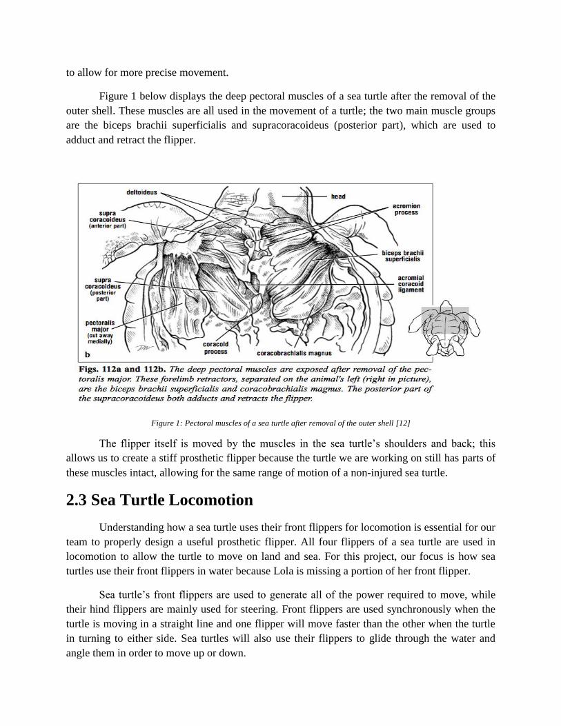
Figure 1 below displays the deep pectoral muscles of a sea turtle after the removal of the
outer shell. These muscles are all used in the movement of a turtle; the two main muscle groups
are the biceps brachii superficialis and supracoracoideus (posterior part), which are used to
adduct and retract the flipper.
Figure 1: Pectoral muscles of a sea turtle after removal of the outer shell [12]
The flipper itself is moved by the muscles in the sea turtle’s shoulders and back; this
allows us to create a stiff prosthetic flipper because the turtle we are working on still has parts of
these muscles intact, allowing for the same range of motion of a non-injured sea turtle.
2.3 Sea Turtle Locomotion
Understanding how a sea turtle uses their front flippers for locomotion is essential for our
team to properly design a useful prosthetic flipper. All four flippers of a sea turtle are used in
locomotion to allow the turtle to move on land and sea. For this project, our focus is how sea
turtles use their front flippers in water because Lola is missing a portion of her front flipper.
Sea turtle’s front flippers are used to generate all of the power required to move, while
their hind flippers are mainly used for steering. Front flippers are used synchronously when the
turtle is moving in a straight line and one flipper will move faster than the other when the turtle
in turning to either side. Sea turtles will also use their flippers to glide through the water and
angle them in order to move up or down.

2.3.1 Lift Forces
Sea turtles will use their flippers at different angles to produce different lift forces and to
direct their movement. Keeping their flippers horizontally allows the sea turtle to glide properly
through the water while angling them up or down helps the turtle to move upwards or dive
downwards similarly to the wings on an airplane.
2.3.2 Powerstroke
The powerstroke is the strongest and most powerful method of swimming for sea turtles.
This process, which is pictured below in Figure 2, shows the locations of the flipper tip during
regular swimming (a) as well as the angles of the flipper at regular swimming (b). Also pictured
is the location of the flipper tip during vigorous swimming (c) and the flipper angles during
vigorous swimming. Sea turtles held in captivity do not experience vigorous swimming because
they are sheltered in small tanks.
2.3.3 Routine Swimming
A typical turtle in the wild will swim at an average cruising speed of roughly one to three
Figure 2: Routine and Vigorous Swimming [13]

mph and can reach speeds of up to twenty mph in quick bursts to escape predators. Routine
swimming for turtles in captivity will result in much less stress and power than a turtle in the
wild. Lola will be spending all of her time in a tank that is roughly 816 cubic feet. Therefore, she
will not reach speeds comparable to speeds reached by sea turtles in the wild. However, her
captivity will provide her prosthesis with other stresses, such as forces acting against it as it
strikes the side of the tank.
2.4 Human Prosthetics
The field of turtle prosthetics is a relatively unchartered territory. There are few examples
of functional turtles prostheses in the world. However, there are countless examples of human
prostheses, which operate under various mechanisms. Research of human prostheses will give us
a better understanding of how these prostheses perform and how they could be potentially
modified and applied to turtles.
2.4.1 Materials
The best method to ensure a secure fit in human prosthetics is to utilize liners, which are
thin sleeves that fit over the residual limb, allowing for a reduction of chafing and unhindered
movement of the prosthesis [14]. There are several types of liners that are made out of various
materials and cater to different situations. The potential materials are: silicone, polyurethane
(PUR), Copolymer, and WintersGel.
2.4.1.1 Silicone
Silicone is widely used in human prosthetics as a liner. It provides good stability and
adhesion, which is useful for soft tissue applications. In addition, silicone is a soft, cushioning
material, which absorbs and distributes pressure, and is easy to clean. It is generally
recommended for individuals with low to moderate activity levels [14].
2.4.1.2 Polyurethane
Polyurethane or PUR, is a commonly used prosthetic sleeve that has many advantages. A
PUR sleeve has the ability to flow away from high pressure, meaning the pressure in the socket
of the prosthesis would be well distributed across the entire sleeve. PURs characteristics and
damping of pressure on the effected limb would make it a good choice for sensitive, bony or
scarred residual limbs. PUR is best suited for individuals from low to especially high activity
levels [14].
2.4.1.3 Copolymer
A copolymer or a thermoplastic elastomer is another liner that is typically used in the
prosthetics field. This type of liner is best suited for individuals who will use it for low levels of
activity [14]. This material does not have seams that could separate after prolonged use,

increasing longevity of the material. Copolymers are more elastic allowing for fitting of more
asymmetric residual limbs [14].
2.4.1.5 WinteresGel
WintersGel was specifically designed for a dolphin named Winter. Dolphins have more
sensitive skin than humans. Even though the material was produced for dolphins, it has been
used in humans for any amputee seeking a more comfortable alternative to traditional liners [15].
Since this material was designed for aquatic mammals, it can withstand the harsh saltwater
environment. WintersGel, as well as the other common liner materials all still have potential
drawbacks caused by perspiration issues, hygiene concerns, lack of breathability and potential
skin breakdowns. However, the benefits of the liner outweigh any of the potential drawbacks.
2.4.2 Methods of attachment
To gain a better understanding of how our prosthetic attachment may work, we will look
into how human prosthetics attach to the body. The typical attachment methods are suction
suspension, vacuum suspension, and shuttle lock prosthesis.
2.4.2.1 Suction suspension prosthesis
This attachment method uses the weight of the patient standing on the connection to
expel the air in between the socket and the liner [15]. This type of prosthesis attachment is
generally used for people who have leg amputations. This method requires two different kinds of
sleeves, a silicone sock that is placed on first to create the seal for the suction. Then a prosthetic
sock is placed over the silicone sleeve for increased comfort [15]. With every step the user takes,
any excess air gets expelled from the socket creating a secure attachment.
2.4.2.2 Vacuum Suspension
A vacuum socket uses the suction of a vacuum to hold the prosthetic onto the limb of the
patient. This vacuum is created by the seal that is created between the limb liner and the edge of
the socket on the prosthesis. An exhaust valve can remove all the air in between the socket and
the limb liner, creating the vacuum holding the prosthesis to the limb [15]. This prosthetic
connection method is one of the most comfortable available as the vacuum evenly distributes the
force across the entire surface area of the socket [15].
2.4.2.3 Shuttle lock prosthesis
This method of prosthesis connection utilizes a padded liner, with a plunger on the end.
This plunger then connects into the prosthesis' socket side, which is a one-way locking device,
preventing the prosthesis from falling off the limb. To remove the prosthesis, simply press a
button on the side releasing the plunger from the one-way lock. This type is one of the easiest
methods to attach and detach; however it is designed for people who have low activity level [15].
In high activity scenarios the shuttle lock method can lead to blisters or sores due to the
connection, which allow rubbing on the limb to occur.
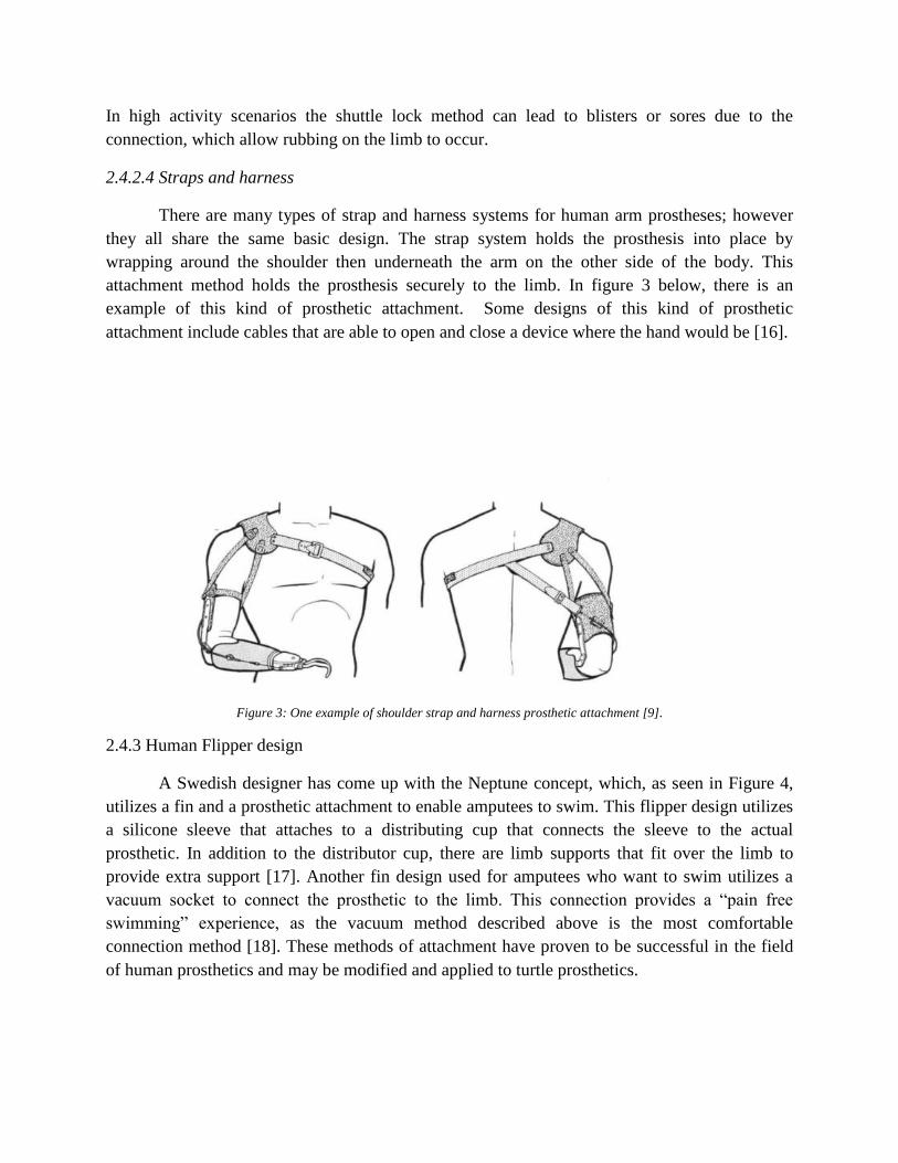
2.4.2.4 Straps and harness
There are many types of strap and harness systems for human arm prostheses; however
they all share the same basic design. The strap system holds the prosthesis into place by
wrapping around the shoulder then underneath the arm on the other side of the body. This
attachment method holds the prosthesis securely to the limb. In figure 3 below, there is an
example of this kind of prosthetic attachment. Some designs of this kind of prosthetic
attachment include cables that are able to open and close a device where the hand would be [16].
Figure 3: One example of shoulder strap and harness prosthetic attachment [9].
2.4.3 Human Flipper design
A Swedish designer has come up with the Neptune concept, which, as seen in Figure 4,
utilizes a fin and a prosthetic attachment to enable amputees to swim. This flipper design utilizes
a silicone sleeve that attaches to a distributing cup that connects the sleeve to the actual
prosthetic. In addition to the distributor cup, there are limb supports that fit over the limb to
provide extra support [17]. Another fin design used for amputees who want to swim utilizes a
vacuum socket to connect the prosthetic to the limb. This connection provides a “pain free
swimming” experience, as the vacuum method described above is the most comfortable
connection method [18]. These methods of attachment have proven to be successful in the field
of human prosthetics and may be modified and applied to turtle prosthetics.

Figure 4: Neptune design to aid amputees while swimming [17].
2.5 Animal Prosthetics
Animal prosthetics is a novel field, especially in the case of aquatic animals. Of these
animal prosthetics, there are even fewer cases of prosthetic flippers being designed for turtles
with amputated flippers. Currently, there are only four turtles in the world that have received
some type of prosthesis and only two turtles which have received a flipper prosthesis, including
Lola. These cases create a baseline in the development and creation of turtle prosthetics.
2.5.1 Allison and Hofesh's Prosthetic Rudder System
Allison, a Green sea turtle, lost a pectoral flipper and both of her pelvic flippers in a shark
attack. Allison was unable to surface for air in pools deeper than 2 feet and could only swim in
circles. An intern at the turtle rehabilitation center where Allison is located designed a rudder
system for her that mimics a canoe paddling technique and allowed her to maneuver better [18].
In this paddling technique, a canoe can be propelled forward by rowing one paddle on one side
of the canoe and by trailing another paddle to create drag. Allison's prosthetic rudder similarly
creates drag and allows her to propel herself forward with her remaining pectoral flipper [18].
The first prototype of Allison's prosthetic flipper included a neoprene wetsuit covering
the majority of her shell, which stabilized the attached plywood rudder, shown in Figure 6 [18].
Allison's prosthetic was altered later to minimize buoyancy effects caused by the plywood. A
carbon fiber rudder was manufactured that uses a clamp mechanism to grip about Allison's shell.
This design uses a ratchet system to secure the prosthesis to Allison, as shown in Figure 5. The

prosthetic device is fixed and remains stationary while in use, and therefore requires little
maintenance. However, this device does not provide Allison with any additional thrust.
Figure 5: Allison's Plywood Prosthesis [18].
Figure 6: (L to R) Carbon Fiber Prosthetic, Ratchet Clamp, Neoprene Wetsuit [18].
Hofesh, another Green sea turtle, developed a similar problem as Allison after being
caught in a fishing net. This accident required both his left pectoral and pelvic flippers to be
amputated [19]. A prosthetic was designed for Hofesh, which included a plastic dual tailfin, as
seen in Figure 7. This fin allowed Hofesh to have better hydrodynamic stability and also helped
him to surface for air and food. Much like Allison's prosthesis, Hofesh's design increased his
mobility and balance in the water. However, the device could not produce any thrust to aid
Hofesh in propulsion.

Figure 7: Hofesh's Prosthetic [19]
2.5.2 Yu Chan's Prosthetic Flippers
The first example of a sea turtle with prosthetic flippers came from a Japanese loggerhead
sea turtle named Yu Chan. This turtle lost half of her left pectoral flipper and a third of her right
pectoral flipper from a shark attack. After numerous iterations, Yu was given a prosthesis, which
consists of two artificial flippers that are attached to a soft vest, which fits over her shell, shown
in Figure 8 [18]. The prosthetic flippers are fixed in place by the vest and a series of adjustable
straps and protect the amputation sites.
Figure 8: Yu's Prosthetic Flippers [18].
Unlike the Allison and Hofesh's prostheses, Yu's flippers provide additional thrust
because they expand the span of each flipper. This larger span, however, also increases the risk
of Yu accidentally hitting other objects and may hinder her movement through more difficult
terrain, such as through seaweed or other vegetation. Additionally, Yu's prosthetic flippers do not
function like natural flippers because they do not utilize her natural lift-based mechanism. The
flippers instead act more similarly to rowing paddles. Compared to natural flippers, this increases
her drag and reduces control.
Yu's case is unique because she was missing both pectoral flippers, meaning that the
prosthetic flippers were not required to replicate the motion of another remaining pectoral
flipper. The attachment of two identical pectoral flippers also allowed Yu to have improved
balance compared to turtles with one prosthetic pectoral flipper and one natural pectoral flipper.
These issues of balance and mirrored locomotion are greater factors in turtles without dual
pectoral flipper amputations.
2.5.3 Winter's Prosthetic Tail
Winter is a dolphin that became entangled in the line of a crab trap, which cut off the
circulation to her tail flukes, thus requiring amputation. Because dolphins use their tails for
propulsion, the loss of Winter's tail decreased her mobility and caused her to adopt a different
motion in an effort to propel herself forward, which was causing additional damage to her
skeletal system.
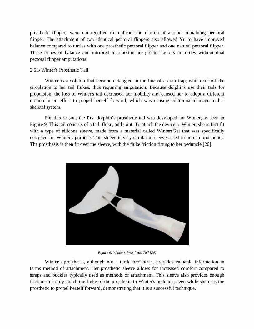
For this reason, the first dolphin’s prosthetic tail was developed for Winter, as seen in
Figure 9. This tail consists of a tail, fluke, and joint. To attach the device to Winter, she is first fit
with a type of silicone sleeve, made from a material called WintersGel that was specifically
designed for Winter's purpose. This sleeve is very similar to sleeves used in human prosthetics.
The prosthesis is then fit over the sleeve, with the fluke friction fitting to her peduncle [20].
Figure 9: Winter's Prosthetic Tail [20]
Winter's prosthesis, although not a turtle prosthesis, provides valuable information in
terms method of attachment. Her prosthetic sleeve allows for increased comfort compared to
straps and buckles typically used as methods of attachment. This sleeve also provides enough
friction to firmly attach the fluke of the prosthetic to Winter's peduncle even while she uses the
prosthetic to propel herself forward, demonstrating that it is a successful technique.
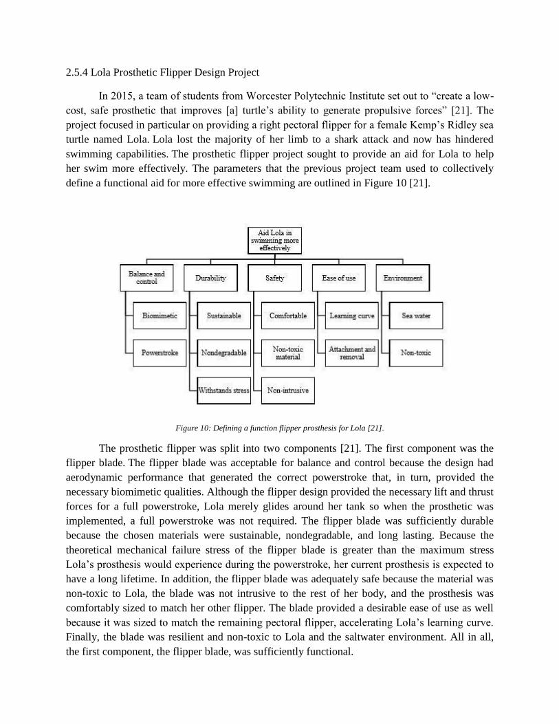
2.5.4 Lola Prosthetic Flipper Design Project
In 2015, a team of students from Worcester Polytechnic Institute set out to “create a low-
cost, safe prosthetic that improves [a] turtle’s ability to generate propulsive forces” [21]. The
project focused in particular on providing a right pectoral flipper for a female Kemp’s Ridley sea
turtle named Lola. Lola lost the majority of her limb to a shark attack and now has hindered
swimming capabilities. The prosthetic flipper project sought to provide an aid for Lola to help
her swim more effectively. The parameters that the previous project team used to collectively
define a functional aid for more effective swimming are outlined in Figure 10 [21].
Figure 10: Defining a function flipper prosthesis for Lola [21].
The prosthetic flipper was split into two components [21]. The first component was the
flipper blade. The flipper blade was acceptable for balance and control because the design had
aerodynamic performance that generated the correct powerstroke that, in turn, provided the
necessary biomimetic qualities. Although the flipper design provided the necessary lift and thrust
forces for a full powerstroke, Lola merely glides around her tank so when the prosthetic was
implemented, a full powerstroke was not required. The flipper blade was sufficiently durable
because the chosen materials were sustainable, nondegradable, and long lasting. Because the
theoretical mechanical failure stress of the flipper blade is greater than the maximum stress
Lola’s prosthesis would experience during the powerstroke, her current prosthesis is expected to
have a long lifetime. In addition, the flipper blade was adequately safe because the material was
non-toxic to Lola, the blade was not intrusive to the rest of her body, and the prosthesis was
comfortably sized to match her other flipper. The blade provided a desirable ease of use as well
because it was sized to match the remaining pectoral flipper, accelerating Lola’s learning curve.
Finally, the blade was resilient and non-toxic to Lola and the saltwater environment. All in all,
the first component, the flipper blade, was sufficiently functional.

The second component of the prosthetic flipper was the attachment system [21]. When
secured, the attachment system allowed the prosthesis to add proper biomimetic and powerstroke
qualities. The durability of the attachment system was satisfactory because the selected material
was nondegradable. However, the system could not withstand the stress of some swimming
motions and would fall off or rotate out of proper alignment during live testing. Overall, the
safety of the attachment system was poor because although it was non-toxic material to Lola, it
was determined to be intrusive and uncomfortable to Lola in live testing. She developed several
calluses and sores while wearing the device. Additionally, the ease of use was also poor because
the attachment system made the attachment and removal of the prosthetic flipper difficult for
Lola’s human handlers in live testing. As for the environment, the attachment system was both
resilient and non-toxic to the seawater environment. When all is considered, the attachment
system did not meet the defined parameters to be defined as functional.
When looking at this success of this project, it is best to look at two components
independently. Based on the parameters the team set out, they were successful in creating a
functional flipper blade. On the other hand, the attachment system fell short of a few crucial
parameters they set out for the project. Several improvements could be made to the system, such
as: reducing the time required to attach and remove the device, allowing for a comfortable fit to
reduce callus formation, and creating a mechanism that would ensure a secure fit without
allowing the device to rotate about the residual limb.

3. Design Chapter
3.1 Client Statement
Our goal with this project was to create a turtle flipper prosthetic that was made custom
for Lola, but could also be adapted to fit any amputee turtle if altered slightly. The device made
for Lola would be thoroughly tested both in-house and in the field after being sent to the
aquarium, so that it could be fully optimized according to both Lola’s needs and the usability of
those applying it to her.
3.2 Existing Need
The need for this device stems from the aforementioned fact that many species of sea
turtles are endangered. Because many of the things that are causing their endangerment cannot
be prevented, such as boating accidents and predator attacks, another way to help this situation is
to give the amputee turtles that survive these incidents prosthetic flippers to aid in their
rehabilitation. On top of that, amputee turtles are unable to mate to reproduce, because they have
to be kept in singular confinement from other turtles in order to not further decrease their quality
of life by having them interact with healthy turtles. Therefore, by giving an amputee turtle a
prosthetic to improve its quality of life, it then could be put back with other members of its
species, then allowing it to hopefully reproduce so that its babies could be released into the wild.
There is no current device in existence that accomplishes this by only attaching to the residual
limb.
3.3 Engineering Problem
The engineering problem that defines this project is how to create a turtle flipper
prosthetic that both mimics the biomimetic locomotion of a healthy flipper and has a high
enough usability so that the device can be easily applied to the turtle quickly and in the correct
orientation.
3.4 Design Criteria
The criteria that the designs were evaluated on were performance, ease of attachment,
safety, durability, manufacturability, and cost. These criteria were also defined in Table 1.
3.5 Engineering Design Standards
The two main types of engineering design standards that would need to be considered in
a project such as this would be industry drafting standards and ethical standards. SolidWorks is
considered a universal tool in industry drafting standards, which would allow for it to be used
and accepted by the majority of those intending to manufacture the design. It follows Military-

Standard-31000A, ASME Y14.41, ISO 16792, and DIN ISO 16792 [24]. Considering ethical
standards, because safety of both all those working on and testing the device will be the top
priority, no ethical standards seem to be of concern.
3.6 Initial Designs
Initially, we developed four comprehensive prosthetic flipper attachment concepts. One
concept used a jacket/harness that completely encompassed the sea turtle’s body to secure the
prosthetic flipper to what is remaining of the turtle’s limb. Another concept involved a custom
fitting glove, which incorporated a pushpin lock to secure the flipper to the turtle’s limb. An
additional idea attached the prosthetic flipper to a flat plate for the base of the residual limb and a
strap that would loop around the limb and secure it to the plate. The last design implemented
dual silicon sleeves and a one-way valve between the two sleeves that would secure the flipper to
the residual limb with vacuum suction.
3.6.1 Jacket Design
The first of the four designs was the Jacket Design, which includes a jacket made of a
neoprene material. This jacket fastens around the turtle’s shell using buckles. The prosthesis is
permanently attached to the jacket using rivets and other fastening mechanisms. Soft silicone and
rubber materials are sewn onto the underside of the neoprene jacket to create additional friction
between the neoprene jacket and the turtle’s shell (Figure 11).
The major benefit to this design was its ability to distribute the pressure from the
prosthesis to other parts of the turtle’s shell, thus reducing the local pressure. Also, this design
provided ease of attachment, with only two snap buckles as points of attachment. However, this
design concept was ultimately abandoned as the Aquarium expressed their concerns of the
turtle’s acceptance of the jacket system.
Figure 11: Initial Jacket Design Concept.

3.6.2 Glove Design
In the second design, the Glove Design has the prosthetic flipper riveted to an attachment
glove. The attachment glove has a prosthetic push pin lock incorporated into it as the securement
method. A silicon sleeve with the pin end for the pushpin lock goes on the residual limb. The
sleeve and glove pushpin lock system secures the flipper to the turtle (Figure 12).
The main appeal of this design is that the attachment glove is customized for the specific
residual limb in question. In order to create the attachment glove, CAD software is used to create
the custom mold that will adhere to the dimensions of the specific residual limb. Another
strength of the design is that the pushpin lock and silicon sleeve are already produced and used
for human prosthetics. This means the locking mechanism has a history of success for
prosthetics, an easy method to secure and release, and simpler manufacturing since it is
commercially available.
Figure 12: Initial Glove Design Concept
3.6.3 Loop and Plate Design
The Loop and Plate design has the prosthetic flipper riveted into a flat plate. The flat
plate has neoprene straps built into it that are looped over the residual limb and pulled taught.
Hence this design is called the Loop and Plate design. A silicon sleeve goes over the residual
limb prior to having the loop and plate secured to it (Figure 13).
The key design feature is the ability to align the flat base of the residual limb with the flat
plate which, in turn, gives the flipper itself the proper orientation. In addition, the combination of
the silicon sleeve and neoprene strap provides desirable friction while still being comfortable for
the turtle. Additional appeal of this design is that it can be applied to many different turtles with

minimal adjustments.
Figure 13: Initial Loop and Plate Design Concept.
3.6.4 Vacuum Design
The final design idea implements dual sleeves and a one-way valve between the two
sleeves that secure the flipper to the residual limb with vacuum suction. The flipper blade is
attached to one of the sleeves in an airtight manner, using glues and resins that are saltwater
compatible to create a seal. The one-way valve is located on the sleeve that is attached to the
flipper blade. A sleeve that is fitted to Lola’s residual limb is also used in this design. To attach
the device to Lola, the fitted sleeve is first applied to her stump. The secondary sleeve with the
attached flipper blade is then applied over the fitted sleeve. A vacuum is then used on the one-
way valve to eliminate any air in between the two sleeves and to create an airtight design (Figure
14).
The main appeal to this design is its custom nature. The prosthesis is custom fitted to
Lola’s stump and changes in her stump, such as calluses or increased muscle mass, do not inhibit
the design in any way. Additionally, with a vacuum-sealed design, the flipper blade cannot rotate
about her stump and slip due to the increased friction between the dual sleeves and its airtight
nature. The biggest concern with this design is the one-way valve and its interaction in a
seawater environment, especially at deeper depths, when the atmospheric pressure increases.

Figure 14: Initial Vacuum Design Concept.
3.6.5 Evaluation of Preliminary Designs
Moving forward, we wanted to focus our efforts on the best design concepts. In order to
determine this, we constructed a design matrix that considered all the features the product
required. These features were performance, ease of attachment, safety, durability,
manufacturability, and cost. However, some of these features were more crucial to the product so
each feature was assigned a weight on a 1-10 scale of how important it was to the product. The
features of each criterion were clearly and understandably defined below in Table 1.
Table 1: Definitions and weights of criteria used in the weighted design matrix
Criteria Weight Definition
Performance 10 The design provides proper alignment and securement on the
stump while allowing forward movement
Ease of Attachment 8 The design is easy to attach to the turtle in a short amount of
time
Safety 7 The design does not cause harm to the turtle or its

environment
Durability 6 The design will last a long period of time in an aquarium
environment
Manufacturability 6 The design is easy to manufacture and replicate for other
turtles
Cost 4 The design will be cost effective
Using the weighted design matrix, each member of our team individually rated on a scale
of 1-10 how well he/she thought the design in question adhered to the criteria. Using the data
from the design matrix, we determined the top 3 designs to pursue were Loop and Plate, Glove,
and Jacket/Harness. The data from the weighted design matrix is below in Figure 15.

Figure 15: Data from weighted design matrix.
3.7 Manufacturing of Designs
3.7.1 Flipper Blades
The previous team of students from Worcester Polytechnic Institute that worked with
Lola manufactured and tested flipper blades. Our group has adopted the design and thrust

characteristics from the past group. Our team manufactured the flipper blades by using Smooth-
Sil 945 and 950. We created four total flippers, two of each type of material. We used Mold Star
15 to create a negative of the 3D printed flipper blade that was acquired from the previous year’s
MQP team (Figure 16). We did this by placing the plastic flipper into a plastic tub and pouring
the liquid mixture around it. We let it cure for approximately four hours, removed the mold from
the plastic tub and then removed the flipper from the mold. Once this negative mold of the
flipper was created, we mixed the Smooth-Sil 945, poured it into this negative mold, and then let
it cure for the recommended time of six hours. We then repeated this process, creating another
flipper blade made of Smooth-Sil 945 and two additional blades made of Smooth-Sil 950 (Figure
17).
Figure 16: Negative mold of the 3D printed flipper blade.

Figure 17: 3D printed flipper blade; Smooth-Sil 945 flipper blade; Smooth-Sil 950 flipper blade.
3.7.2 Glove Design
To manufacture this design, we solicited help from Hanger Prosthetics in Worcester, MA.
A prosthetist demonstrated the different sleeves and locking mechanisms that are used in human
prosthetics. From Hanger Prosthetics we received two different sleeves to be used on the residual
limb. One of the received sleeves is made of silicon and is used in combination with the Loop
and Plate Design. The other sleeve is a combination of rubber and waterproof fabric as well as a
male end of a locking system incorporated into the end of the sleeve. We also received two
shuttle locks from Hanger Prosthetics that we used in our final design. These shuttle locks act as
the female end of the locking system, which connect, to the male end of rubber sleeve. The
shuttle locks and the rubber sleeves were used in the Glove Design.
Figure 18: The 3D printed piece used to create the mold for the final design.

To create a custom fit glove, we adopted the following procedure:
● We 3D printed the hollow glove shape that we designed in Solidworks (Figure
18). This shape was specifically designed to accurately depict the outer walls of
our custom fit glove.
● We created a negative mold of the 3D printed shape using Mold Star 15.
● The molded residual limb was placed inside the rubber sleeve.
● The sleeve was attached to the shuttle lock and wrapped in plastic and duct tape to
prevent it from getting stuck within the mold.
● A piece of PVC piping was placed over the shuttle lock’s release button to
maintain its functionality after the mold was poured.
● We placed a 3D printed flipper blade cap into the bottom of the mold to simulate
the actual flipper blade and create a space to firmly place the molded flipper
blades after the molded glove was completed (Figure 19).
● We placed the entire residual limb, rubber sleeve, and shuttle lock system into the
negative mold created by the 3D printed hollow glove shape.
● We poured the mixed Smooth Cast 325 into the mold.
● Once the cast fully cured, it was removed from the mold.
When we removed the glove from the mold, we noticed areas where the pour did not
settle evenly. Some of the areas were very thin which compromised the strength and durability of
the glove. Our group poured additional material onto the thin spots to increase the strength.
Then, we filed and sanded the abrasive spots on the glove to ensure the swimming dynamics
were not compromised and that there were no sharp parts of the glove, which could cause harm
to the turtle and/or environment. We also cut a hole for the shuttle lock’s release button so it
could be accessed. The last step was to attach the flipper to the custom glove. To better secure
the flipper in place, we riveted the flipper to the glove and poured additional Smooth-Sil material
in the space between the flipper and glove. The final Glove Design is shown in Figure 20.

Figure 19: 3D printed cap of the Flipper Blade.
Figure 20: Final two glove designs and the sleeve.
3.7.3 Loop and Plate Design
To manufacture the Loop and Plate Design, we designed a part in Solidworks that
consisted of a flat plate with slits, connected to a hollow elliptical shape, which would accept the
flipper blade. This part was 3D printed with an XYZ DaVinci 1.0 printer to be nearly solid using
ABS plastic (Figure 21).

Figure 21: 3D Printed Loop and Plate part.
We then cut an off-the-shelf Velcro strap to size and sewed neoprene material to the
underside of the strap to create additional friction between the Velcro strap and the silicone
sleeve provided by Hanger Prosthetics. We fed this custom strap through the slits within the 3D
printed part. Finally, the flipper blade was riveted to the 3D printed part and additional Smooth-
Sil material was inserted into the slot that the flipper slid into to better secure the flipper into
place. The completed design can be seen in Figure 22.

Figure 22: Completed Loop and Plate Designs.
3.8 Testing
3.8.1 Deflection Testing
We tested the flexibility of the two flipper blades and compared it to the flexibility of the
flipper that the Key West Aquarium is currently using. We created a simple deflection test that
the Aquarium could replicate for a direct comparison. We anchored the flippers horizontally at
their bases and suspended them over the side of a table without applying any additional force to
the flipper. We then measured the deflection that was created by their own weight at the tip of
the blades. The Smooth-Sil 950 and 945 flipper blades deflected 1.5 inches (Figure 23) and 1
inch (Figure 24) respectively. The aquarium was able to perform the same test with the flipper
that is in current use. This flipper deflected 1 inch (Figure 25).

Figure 23: Flipper made of Smooth-Sil 950 deflecting 1.5 inches.
Figure 24: Flipper made of Smooth-Sil 945 deflecting 1 inch.

Figure 25: Flipper currently being used at the aquarium deflecting 1 inch.
3.8.2 Pressure Testing
To determine that our designs would not injure the turtle through the compressive stress
applied on the stump, we completed a pressure test on the stump. We completed pressure testing
by using Flex Force gauges (Figure 27) to calculate the force produced by the attachment piece
on the residual limb. To calibrate the force gauges we used a weight set to achieve a baseline
resistance at different weight intervals as outlined in Figure 26. Then using the results we were
able to calculate a function that represented the equivalent force the stump encountered during
the loading cycles. Then using the area of the sensor we can then calculate the pressure produced
by the attachment on to the residual limb. The chart below is our calibration test for the force
gauge.

Figure 26: Calibration Testing Results.
Figure 27: Setup for pressure testing.
We placed the force gauge in two different locations on the stump for the first two
designs, at the top and at the bottom and tested three different loading scenarios. In the third and
final design in addition to the two other locations we also tested on the end of the stump. The
three test points are shown in Figure 28.
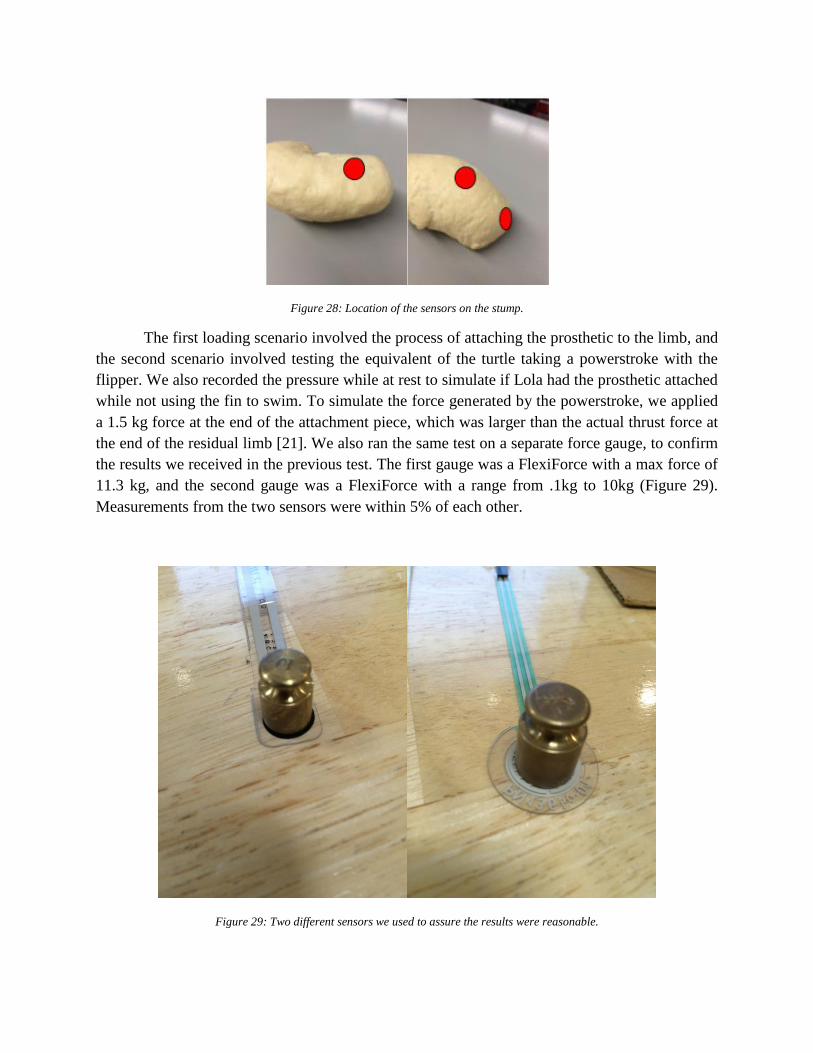
Figure 28: Location of the sensors on the stump.
The first loading scenario involved the process of attaching the prosthetic to the limb, and
the second scenario involved testing the equivalent of the turtle taking a powerstroke with the
flipper. We also recorded the pressure while at rest to simulate if Lola had the prosthetic attached
while not using the fin to swim. To simulate the force generated by the powerstroke, we applied
a 1.5 kg force at the end of the attachment piece, which was larger than the actual thrust force at
the end of the residual limb [21]. We also ran the same test on a separate force gauge, to confirm
the results we received in the previous test. The first gauge was a FlexiForce with a max force of
11.3 kg, and the second gauge was a FlexiForce with a range from .1kg to 10kg (Figure 29).
Measurements from the two sensors were within 5% of each other.
Figure 29: Two different sensors we used to assure the results were reasonable.

Figure 30: Pressure testing of Loop and Plate Design.
When we tested the Loop and Plate design in the water, a team member’s closed hand
was used in place of the mold of the turtle’s residual limb to simulate the limb in the attachment.
To test this design, we placed a sensor on the top of the stump where it is contact with the strap
and on the bottom of the stump, near the end of the limb (Figure 31). After we converted the
resistance to pressure, the highest pressure value we recorded for the loop and plate design was
4,700 Pa. When we tested the pressure levels in the glove design we placed the sensor on top of
the stump and on the bottom and near the end of the residual limb. We calculated the maximum
pressure for the glove design to be 20,300 Pa from the area of the force gage. When a pressure of
20,300 Pa is applied to a human for five consecutive hours blisters and sores will begin to form
[22]. We determined that this would not be an issue for Lola because the aquarium will not be
applying the prosthesis for that length of time until her residual limb adjusts to the prosthesis.

Figure 31: Setup for pressure testing on glove design.
When testing our final glove design we tested in three locations the top, bottom, and end
of the residual stump. The resulting pressures from our final design can be seen in Table 2
below. We can see that our final design produced a lower amount of pressure from the previous
glove design and the maximum recorded pressure being approximately 7260 Pa.
Table 2: Results from the pressure testing on the final Glove Design

When looking into the pressure data, we can see that the loop and plate had the lowest
pressure while the original design had the greatest. Our final design was between those values,
only creating 7,260 Pa of pressure at a point, and this only occurred during the power stroke
motion of swimming. To ensure that that the pressure is not high enough to cause ulcers, we
compared this pressure to the pressure that is required to create ulcers in humans, due to the fact
that there is little to no ulcer research on turtles. We found that in humans, complications from
constant pressure starts to form at a magnitude of approximately 4,400 Pa, applied for a critical
duration of time [23]. From that number, we conclude that the constant pressure produced by the
prosthesis is in a healthy range for Lola, as the normal pressure is approximately 3,000 Pa. The
powerstroke pressure is over this limit, however, this load would not be applied for a critical
amount of time.
3.8.3 Water Testing
To determine whether or not these designs could perform as expected in real world
situations, we conducted a performance test in the WPI pool. Kemp’s Ridley sea turtles can
generate a maximum flipper speed of approximately 50 cm/s (MQP number). To closely mimic
real world scenarios, we replicated this maximum flipper speed in the water during testing. We
tested two different scenarios or loading conditions for the attachment. The first scenario
simulated the turtle swimming normally through the water. The second test determined the
design’s ability to stay attached to the team member’s hand during an increased load. This test
simulated the turtle thrashing with the prosthesis on.
During each loading scenario for the two designs, both attachments succeeded in
remaining secure. There was no slippage or rotation of the attachment, even while testing
thrashing conditions. This demonstrated that both attachments would adhere to the amputation
site securely during both normal swimming and during aggressive thrashing. A photo of the
testing is shown in Figure 32.
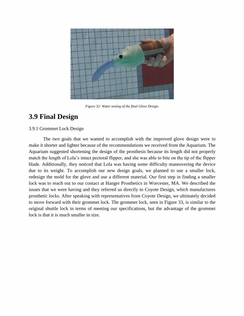
Figure 32: Water testing of the final Glove Design.
3.9 Final Design
3.9.1 Grommet Lock Design
The two goals that we wanted to accomplish with the improved glove design were to
make it shorter and lighter because of the recommendations we received from the Aquarium. The
Aquarium suggested shortening the design of the prosthesis because its length did not properly
match the length of Lola’s intact pectoral flipper, and she was able to bite on the tip of the flipper
blade. Additionally, they noticed that Lola was having some difficulty maneuvering the device
due to its weight. To accomplish our new design goals, we planned to use a smaller lock,
redesign the mold for the glove and use a different material. Our first step in finding a smaller
lock was to reach out to our contact at Hanger Prosthetics in Worcester, MA. We described the
issues that we were having and they referred us directly to Coyote Design, which manufactures
prosthetic locks. After speaking with representatives from Coyote Design, we ultimately decided
to move forward with their grommet lock. The grommet lock, seen in Figure 33, is similar to the
original shuttle lock in terms of meeting our specifications, but the advantage of the grommet
lock is that it is much smaller in size.

Figure 33: Grommet Lock From Coyote Design.
With the new lock for our design, several design modifications were needed. The first
adjustment shortened the flipper blade itself by 3.7 inches. This correction created a proper
stump to tip of flipper length of 6.3 inches. The next adjustment involved shifting the grommet
lock’s alignment off-center from the center of the flipper. In the previous design, with the center
alignment of the shuttle lock, the pushpin release was flush with the edge of the flipper.
However, since the grommet lock’s radius is smaller than that of the shuttle lock, the lock’s
position was moved off the center of the flipper in order to maintain the flush alignment between
the pushpin release and the edge of the flipper. Making the pushpin flush with the edge of the
flipper ensures that it can be pushed easily for release. To make the prosthesis’ design more
compact, the lock was designed to overlap with a portion of the flipper blade. The portion of the
flipper that overlapped with the lock had to be cut 2.4 inches. This cut allowed the maximum
surface area of flipper blade in the prosthesis in order to ensure the flipper was securely attached
to the glove. The adjustments made to the original design are outlined below in Figures 34 and
35.
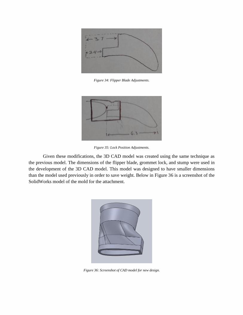
Figure 34: Flipper Blade Adjustments.
Figure 35: Lock Position Adjustments.
Given these modifications, the 3D CAD model was created using the same technique as
the previous model. The dimensions of the flipper blade, grommet lock, and stump were used in
the development of the 3D CAD model. This model was designed to have smaller dimensions
than the model used previously in order to save weight. Below in Figure 36 is a screenshot of the
SolidWorks model of the mold for the attachment.
Figure 36: Screenshot of CAD model for new design.

Our last adjustment to make the prosthetic significantly lighter was to find a different
material to make the cast with. On the original glove design, we used Smooth Cast 325 which
worked very well in creating a hard cast that would not be damaged, however its weight made it
useless once we sent it to the aquarium. To lighten the cast, we decided to use a material called
Feather Lite. The Feather Lite material is very similar to the Smooth Cast 325 material in terms
of durability, ease of use and strength. One common use for this material is in fishing lures,
which are used in the same environment that Lola lives in. The Feather Lite material had a
significantly lower density as compared to the Smooth Cast 325, which contributed largely to
decrease the weight of the final product. The first complete prototype with the flipper and
[Smooth Cast 325] glove weighed 640 grams. The complete final product with the flipper and
[Feather Lite] cast weighed 305 grams.
3.9.2 Manufacturing of Grommet Lock
The manufacturing process of this design was very similar to the process we performed
on the first glove design. We used the 3D printed hollow glove shape to create a mold using the
same Mold Star 15. Once the mold was fully cured we took the mold of Lola’s residual limb,
placed it in the sleeve and attached it to the new Grommet Lock with a small piece of ¾” PVC
pipe over the release to prevent the material from forming around the release making it
impossible to press. We also wrapped the lock and sleeve in saran wrap to keep the Feather Lite
from leaking inside the lock making it unable to release once it hardens. Feather Lite material is
much less dense and takes much longer to cure than the previously used Smooth Cast 325
material. This resulted in much of the material leaking into the Grommet Lock, and we could not
release the mechanism from the stump. We then were forced to break apart the prosthetic to try
and fix the Grommet Lock to hopefully reuse it in a new design, unfortunately we were unable to
remove the material from the Grommet Lock and the pin was unable to be removed. In our
second attempt, we replicated the same manufacturing techniques, but this time we utilized
additional wrap and duct tape to prevent leaking. This worked perfectly and we were able to
remove the sleeve and mold of Lola’s residual limb by using the release on the Grommet Lock.
Then to attach the flipper to the prosthesis we cut the flipper much shorter to fix the original
issue of the design being too long, and also cut the flipper to fit inside the bottom of the cast as
tight as possible. We then poured Smooth-Sil 945, which is the same material as the flipper, to
act as an adhesive to create a tight fit for the flipper.

4. Field Testing Once the first generation Loop and Plate and Shuttle Lock designs, as well as the final
Grommet Lock design, were manufactured and tested, they were shipped to the Key West
Aquarium to be used on Lola in field-testing. The Aquarium's employees handled all three
prostheses and Lola was given an opportunity to swim and test the three devices.
4.1 Loop and Plate Design
The main complaint with both of the manufactured prostheses was their overall length.
Compared to the original prosthesis manufactured by previous WPI students, the Loop and Plate
design measured an additional 2.5 inches. Because of this extra length, Lola was able to bite the
prosthetic flipper and cause it damage. Additionally, this prosthesis was a bit heavier than Lola's
previously manufactured flipper, weighing 399 grams compared to 286 grams. The Aquarium
also expressed some concerns on the ease of attachment and the secureness of the prosthesis.
Lola's handlers had difficulties attaching the device to her residual limb, and because it was not
always attached correctly, it often came loose while Lola was swimming.
4.2 Shuttle Lock Design
Similarly to the Loop and Plate Design, the additional length of the Shuttle Lock
prosthesis was a cause of concern. This device measured ten inches, compared to the six inches
of the previously manufactured prosthesis (Figure 37). Another complication of this design was
its weight of 655 grams, compared to the previous 286 grams. The Aquarium employees noticed
that Lola was having trouble maneuvering the flipper through the water due to its weight, which
made it more of a hindrance for her than an advantage. However, overall, Lola's handlers had
very positive reactions to the device; they stated that the prosthesis was easy to use and the
application time of the device was timed at 2-3 minutes, compared to the 10-minute attachment
time of Lola's previous flipper.

Figure 37: (T-B) Loop and Plate Design, Shuttle Lock Design, and Previous Design Prostheses Lengths.
After field testing data was collected and assessed on the first generation Loop and Plate
and Shuttle Lock designs, the team and the Aquarium decided it would be most beneficial to
move forward with a second generation of the Shuttle Lock device and to eliminate the Loop and
Plate device due to inadequate performance.
4.3 Grommet Lock
The team manufactured the Grommet Lock prosthesis to address the feedback provided
by the Key West Aquarium and shipped the device to be used in field testing. Because a new,
lightweight material was used in the design, the total device weight was 305 grams, 19 grams
heavier than Lola's previous prosthesis. This additional weight did not have an effect on Lola's
swimming abilities, as she was able to maneuver through the water with ease. Additionally, the
device was properly sized at six inches in length, making it impossible for Lola to bite the flipper
blade to damage it. According to the Aquarium, the biggest attribute to this design was its ease in
attachment. Similarly to the Shuttle Lock device, the attachment time of this prosthesis was
timed at 2-3 minutes, thus decreasing the attachment time fivefold. The Grommet Lock
prosthesis also remained securely attached to Lola's stump as she swam through the water. It
maintained a proper orientation and did not spin about her residual limb.
The Aquarium did note that there were some minor modifications that they would make to
the device in the future. The caudal edge of the device was rubbing against the back aspect of

Lola's elbow, creating a blister. To remedy this, they removed a one cm semicircle at the caudal
edge, which proved to be successful. Also, they expressed an interest in developing a prosthesis
in a more natural coloration. But, they also noted that Lola and the other aquatic animals in her
tank did not seem to mind the unnatural color scheme. Overall, the reaction to the Grommet
Lock prosthesis was very favorable, both by Lola and her handlers. The prosthesis met our
desired goals in performance, ease of attachment, environmental safety, and durability, with an
expected lifespan of two years. The Key West Aquarium has already expressed interest in
applying the technology used in the Grommet Lock prosthesis to other sea turtles with similar
injuries, demonstrating the design's definitive success.

5. Final Design Validation
Section 5.1 outlines the basic manufacturability of the final design, while Section 5.2
details the sustainability of the prosthesis. In Section 5.3, the ethical concerns of the device are
discussed, and Section 5.4 references the health and safety issues that were considered. Section
5.5 hits on the economic impact of the final design, Section 5.6 does the same with the
environmental impact, and Section 5.7 goes into the societal impact. Political ramifications are
considered in Section 5.8, while section 5.9 delves into the knowledge of contemporary issues.
5.1 Manufacturability
The final design is intended to be simple to manufacture for any turtle based off the
process used for Lola’s model. The flipper blade would only need to be scaled in size with
accordance to the size of the turtle the prosthesis was being created for. When creating the
attachment piece of the device, a cast of the residual limb would need to be made, so that the
critical points could be measured, and these measurements could be applied to the SoldWorks
file.
5.2 Sustainability
This device is completely passive, in that it requires no external energy in order to
operate it, only needing the turtle’s muscle movement to perform. Many of the materials used in
the device are durable and are expected to last for multiple years when being used by a turtle in
captivity. The process of manufacturing the device has many components that could be reused to
make more devices for other turtles.
5.3 Ethical Concerns
As this device is only intended to improve both the quality of life of amputee sea turtles
and the usability for those applying it, there should be no ethical concerns for its existence. If the
device were to evolve and other factors would be applied to its creation, then this may need to be
reconsidered.
5.4 Health and Safety Issues
The device is currently completely safe for a turtle to use and use with any other turtles
around it. No sharp edges, hazardous materials, or dangerous methods were used in its
manufacturing. If the device were to fail, it would be in a way that would not be hazardous to
any of the turtles, and it would be easy to identify the oncoming failure of the device through
gradual wear and tear.
5.5 Economics

This prosthesis was created to meet a need for amputee turtles, not to fit a need for a
market. The device is not being patented, and the manufacturing process is being thoroughly
documented in this report so that others could recreate this design to help more turtles. It is
constructed of affordable materials and simple manufacturing methods so that the creation of the
prosthesis is very accessible.
5.6 Environmental Impact
The device is comprised entirely of moldable silicones and plastics, along with a sleeve
and lock mechanism that’s commonly used in human prosthetics today. The materials are all
nondegradable, nonhazardous, and waterproof, so that the device should have no impact on
Lola’s confined environment, or the environment as a whole. The manufacturing process itself
also had no impact on the environment, as proper use and disposal of all materials was followed.
5.7 Societal Impact
This device is being publicly acknowledged by staff members at the Key West Aquarium
in Florida when it’s in use by Lola. It’s also being publically referenced by many forms of
media. All of this will hopefully drum up some a greater awareness that sea turtles are
endangered and need the help of humans to survive. Also, publicity for this device can hopefully
reach other individuals in possession of amputee sea turtles, who can then follow the
manufacturing guidelines detailed in this report to create their own prostheses to help more
turtles.
5.8 Political Ramifications
This device is free to be replicated and used by any individual to help an animal in need,
and therefore should have no impact on the political landscape.
5.9 Knowledge of Contemporary Issues
The main contemporary issue this project is involved in is the endangerment of animals
in general. It varies from animal to animal how thoroughly the specie’s state is publically
referenced, and because sea turtles are not highly defended by the public today, this device is
meant to greatly improve their chance for survival. As this device is only intended to have
positive ramifications, it properly aids in the attempt for a solution to the contemporary issue.

6. Conclusion
The goal of this project was to create a sea turtle prosthesis that adheres to the residual
limb securely, easily, and efficiently in order to achieve proper biomimetic locomotion. Our
strategy for achieving biomimetic locomotion was to create a prosthesis that maintained a natural
range of motion and consistent, proper alignment. These qualities, combined with minimizing
the prosthesis’ weight, application time, and difficulty, were all factors that contributed to the
design process of our prosthesis.
The critical component of our securement method was a grommet lock from Coyote
Design. The grommet lock was the best fitting solution because in addition to being water
resistant, it was the smallest and lightest (24 grams) available push pin release lock that could
handle the adequate force loads. The past design often fell off because its securement method
was too weak. With the addition of the grommet lock and a tacky prosthetic sleeve, the
securement of the new prosthesis on Lola’s residual limb was sound and much stronger than the
prosthesis manufactured by the previous WPI students.
The flipper blade created proper alignment every time the prosthesis was attached to the
stump. The glove portion of the prosthesis was custom-made to fit Lola’s residual limb. The
customization of the glove provided only one possible orientation for the prosthesis to attach to
Lola’s stump, creating a consistent flipper-blade alignment while also giving Lola a comfortable
fitting device. In addition, the previous year’s design incorporated many different Velcro straps
to secure the flipper to the amputation site. This made the attachment process long and tedious.
Because of the simplicity of our new prosthesis, the attachment time was decreased fivefold,
making the process less stressful for both Lola and her handlers. Our prosthesis also helped Lola
achieve biomimetic motion on her amputated limb. The created device matched the size of her
healthy flipper, allowing for balanced movement. With the help of the new prosthesis, she could
properly complete a full power stroke. Our final prosthesis attachment weight was very similar to
that of the original prosthesis. After incorporating featherlight material into our final design, the
total weight was 305 grams. That is less than a 7% increase in weight from the original design
for a large increase in usability of the attachment.
Overall, the created prosthesis was deemed a success. Only minor alterations were made
to the design to make it more suitable to Lola. With additional minute adjustments, other sea
turtles around the world with flipper amputations could use the grommet lock design. This could,
in turn, decrease the amount of euthanized turtles, allow amputee turtles to mate, and turn the
tide of sea turtle extinction.

7. Recommendations
Our project focused on improving the usability of a prosthetic turtle flipper by reducing the
time of attachment, increasing the consistency of the alignment, and modifying the design to
make it easy to recreate for other turtles. As it currently stands, this device sets a strong starting
point for a prosthesis that can be widely reproduced to help more turtles. Basic metric goals and
evaluations were used to assess the success of the device that was created, but more long term
field studies could be conducted to further improve the design.
One aspect of the design that has been brought to our attention after immediate field-testing is
the collar rubbing against Lola’s elbow and creating a blister. Staff members of the aquarium
have since cut a semicircle around the elbow and reported that to solve the problem. It is for that
reason that a simple alteration to the design, which angles the collar of the device down and
away from the elbow, should serve as an apt solution.
Going beyond single pectoral amputee turtles, many turtles lose multiple flippers, mainly in
predator attacks. Because of this, the concept of a single flipper prosthesis would need to be
expanded to accommodate such injuries. Initial thoughts are to secure multiple prostheses on a
single turtle through the use of a vest that would hold everything in place. This would be
necessary because more missing limbs would lead to greater instability in the turtle’s movement,
so the vest prosthesis would be needed to prevent any of the devices from falling off.
A more long-term form of field-tests would benefit the progress of the device by revealing
issues that could not be predicted in the in-lab design process. A clear example of this is the
collar of the device leading to blisters on the turtle’s elbow. There was no way to predict this
issue in-lab, as the model of Lola’s stump was only from above her elbow, but it was quickly
discovered once she started using the device. Another long-term concern that does not directly
relate to the turtle is how the device itself degrades with use. Constant stress and fatigue from
being attached to a turtle on a daily basis could uncover mechanical weaknesses that in-house
pressure and pool testing did not, which could lead to later revisions of the device.
Any worker at any aquarium with basic design software exposure could create this current
device, but some potential alterations would require a greater level of manufacturing ability.
Such changes could include more points of mobility in the flipper, or better accounting for
rotation in the power stroke motion that has been lost. Location sensors that could measure force
and velocity would be necessary to determine the difference in motion between the healthy and
prosthetic flippers, and from there, proper design alterations could be made to address these
differences. With minor alterations, this design could have a mass appeal to sea turtles across the
world afflicted with flipper amputations, thus reducing the rate of sea turtle euthanasia.

References
[1] Defenders of Wildlife. (2016). Basic Facts About Sea Turtles. Retrieved October 07, 2016,
http://www.defenders.org/sea-turtles/basic-facts
[2] Endangered Species Act (7 U.S.C. § 136, 16 U.S.C. § 1531 et seq.)
[3] Sea Turtle Conservancy. (2015). Sea Turtles: Why Care? Retrieved October 07, 2016,
http://www.conserveturtles.org/seaturtleinformation.php?page=whycareaboutseaturtles
[4] Hannan, L.B., Roth, J.D., Ehrhart, L.M., Weishampel, J.F. (2007). Dune vegetation
fertilization by nesting sea turtles. Ecology 88(4): 1053-1058.
[5] Feild, Reshad Field. (2002). The Last Barrier: A Journey into the Essence of Sufi Teachings,
Publisher: Lindisfarne Books, ISBN 1584200073.
[6] C. Benjamin MA, Medline Plus. (2014). Leg or Foot Amputation, Retrieved October 07,
2016, https://medlineplus.gov/ency/article/007365.htm
[7]Seaturtle-World. (2014). Sea Turtles in Captivity. Retrieved October 07, 2016,
http://www.seaturtle-world.com/sea-turtles-in-captivity/
[8] http://www.seaturtleinc.org
[9] Wyneken, J. (1997). Sea turtle locomotion: mechanisms, behavior, and energetics. The
biology of sea turtles Vol. 1. CRC Press.
[10] http://www.newworldencyclopedia.org/entry/Turtle
[11] http://www.sportsmd.com/performance/muscle-imbalance-common-overuse-injuries/.
[12] Wyneken, J., & Witherington, D. (2001). The anatomy of sea turtles (p. 172). National
Marine Fisheries Service.
[13] Davenport, J., Munks, S. A., & Oxford, P. J. (1984). A comparison of the swimming of
marine and freshwater turtles. Proceedings of the Royal Society of London B: Biological
Sciences, 220(1221), 447-475.
[14] How liners work. (2016). Retrieved October 07, 2016, from
http://www.ottobockus.com/Prosthetics/info-for-new-amputees/prosthetics-101/how-
liners-work/
[15] WintersGel Prosthetic Liners. (2015). Retrieved October 07, 2016, from
http://www.hangerclinic.com/limb-loss/adult-lower-extremity/adv-
tech/Pages/WintersGel-Prosthetic-Liners.aspx
[16] Pursley, R. J. (1955). Harness patterns for upper-extremity prostheses.Artificial limbs, 2(3),
26.http://opmarketing.com/storage/Research%20EncyclOPedia/Vacuum%20Assisted%2
0Suspension/Street-%20Vac%20Effect%20on%20RL.pdf

[17] LaBarre, S. (2010, June 23). Prosthetic Flipper Turns Amputees Into Mermen. Retrieved
October 07, 2016, from https://www.fastcompany.com/1662946/prosthetic-flipper-turns-
amputees-mermen
[18] Krassenstein, B. (2014, October 31). Elle: The Incredible 3D Printed Swimming Leg for
Amputees. Retrieved October 07, 2016, from https://3dprint.com/22221/elle-swimming-
prosthetic/
[19] [1] "Allison's Prosthesis." Allison’s Prosthesis. Sea Turtle Inc., Retrieved from
http://www.seaturtleinc.org/rehabilitation/allison/.
[13] [2] Iacurci, Jenna. (2014, May 17). "Sea Turtle Amputee Swims Again with Jet-Like
Prosthetic Fin." Nature World News. Retrieved from
http://www.natureworldnews.com/articles/7110/20140517/sea-turtle-amputee-
swimsagain-with-jet-like-prosthetic-fin.htm.
[14][3] Wang, Yue. (2013). Disabled Sea Turtle Gets 27th Pair of Artificial Fins. Time.
Retrieved from http://newsfeed.time.com/2013/02/22/disabled-sea-turtle-gets-27th-pair-
ofartificial-fins/.
[15][4]"Winter", Clearwater Marine Aquarium, 2016. [Online]. Available:
http://www.seewinter.com/winter. [Accessed: 07- Oct- 2016].
[21] Liang, V., Varela, S., and Wong, I. (2016). Design of a Prosthetic Flipper for a Kemp’s
Ridley Sea Turtle. Major Qualifying Project, Worcester Polytechnic Institute
[22] Loerakker, S. (2007). Aetiology of pressure ulcers. Eindhoven University of Technology,
Dept. of Biomedical Engineering, Section Materials Technology, Div. Biomechanics and
Tissue Engineering.
[23] Agrawal, K., & Chauhan, N. (2012). Pressure ulcers: Back to the basics. Indian Journal of
Plastic Surgery : Official Publication of the Association of Plastic Surgeons of India,
45(2), 244–254. http://doi.org/10.4103/0970-0358.101287
[24] Technical Communications Packages. (2016). Dassault Systemes. Retrieved from
https://www.solidworks.com/sw/products/technical-communication/packages.htm.